WO2015012291A1 - 車線維持支援装置 - Google Patents
車線維持支援装置 Download PDFInfo
- Publication number
- WO2015012291A1 WO2015012291A1 PCT/JP2014/069388 JP2014069388W WO2015012291A1 WO 2015012291 A1 WO2015012291 A1 WO 2015012291A1 JP 2014069388 W JP2014069388 W JP 2014069388W WO 2015012291 A1 WO2015012291 A1 WO 2015012291A1
- Authority
- WO
- WIPO (PCT)
- Prior art keywords
- torque
- driver
- timer
- cancel
- control
- Prior art date
- Legal status (The legal status is an assumption and is not a legal conclusion. Google has not performed a legal analysis and makes no representation as to the accuracy of the status listed.)
- Ceased
Links
Images




Classifications
-
- B—PERFORMING OPERATIONS; TRANSPORTING
- B62—LAND VEHICLES FOR TRAVELLING OTHERWISE THAN ON RAILS
- B62D—MOTOR VEHICLES; TRAILERS
- B62D15/00—Steering not otherwise provided for
- B62D15/02—Steering position indicators ; Steering position determination; Steering aids
- B62D15/025—Active steering aids, e.g. helping the driver by actively influencing the steering system after environment evaluation
-
- B—PERFORMING OPERATIONS; TRANSPORTING
- B60—VEHICLES IN GENERAL
- B60W—CONJOINT CONTROL OF VEHICLE SUB-UNITS OF DIFFERENT TYPE OR DIFFERENT FUNCTION; CONTROL SYSTEMS SPECIALLY ADAPTED FOR HYBRID VEHICLES; ROAD VEHICLE DRIVE CONTROL SYSTEMS FOR PURPOSES NOT RELATED TO THE CONTROL OF A PARTICULAR SUB-UNIT
- B60W2510/00—Input parameters relating to a particular sub-units
- B60W2510/20—Steering systems
- B60W2510/202—Steering torque
Definitions
- the present invention relates to a lane keeping support device that performs steering control for lane keeping.
- the lane keeping assist device causes the actuator to generate a steering torque when the vehicle is about to deviate from the traveling lane or after deviating.
- the lane keeping control device is sometimes called a lane departure prevention device or a lane departure prevention device.
- control torque generated by the steering control for maintaining the lane.
- the condition for canceling the generation of the control torque is, for example, that the torque input from the driver to the steering wheel (hereinafter referred to as the driver torque) continues for a certain period of time.
- Patent Document 1 when the driver torque is input in a direction opposite to the control torque, that is, when the driver torque is input in a direction deviating from the lane, the longer the time during which the driver torque is input, A technique for weakening the control torque is disclosed. Thereby, when the driver tries to change the lane, the uncomfortable feeling felt by the driver due to the generation of the control torque in the direction opposite to the driver torque can be suppressed.
- the uncomfortable feeling given to the driver can be reduced even in the above situation.
- the control torque is weakened in a short time, the control is likely to be canceled despite the situation where the steering control for maintaining the lane should not be canceled.
- control torque cannot often be generated in a situation where the control torque should be generated.
- the present invention has been made on the basis of the above circumstances, and its main purpose is to reduce the situation in which the generation of control torque is suppressed, and to suppress the sense of discomfort given to the driver. To provide an apparatus.
- the lane keeping assist device is mounted on a vehicle, and a control torque output unit (12, 12A) that outputs a control torque for keeping the vehicle in a running lane and a vehicle driver by a vehicle driver.
- the driver's intention is reflected in the driver torque. Therefore, by changing the time from when the driver torque is input according to the driver torque to when the output of the control torque is stopped, the time can be matched to the driver's intention. Therefore, it is possible to suppress the uncomfortable feeling given to the driver while reducing the situation where the generation of the control torque is suppressed.
- FIG. 1 is a block diagram illustrating an overall configuration of a lane keeping support system according to a first embodiment.
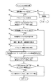
- 5 is a flowchart illustrating a cancel determination process executed by a calculation unit of the lane keeping support system according to the first embodiment.
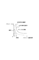
- the conceptual diagram which shows the relationship between driver torque and cancellation delay time.
- the conceptual diagram which shows the relationship between a vehicle speed, a horizontal position, a road curvature, and cancellation delay time.
- the block diagram which shows the whole structure of the lane maintenance assistance system which concerns on Embodiment 2.
- FIG. 7 is a flowchart showing a cancellation determination process executed by a calculation unit of the lane keeping support system according to the second embodiment.
- the conceptual diagram which shows the integral value line showing the cancellation torque integral value.
- Embodiment 1 of the present invention will be described with reference to the drawings.
- a white line or the like drawn on the road is referred to as a lane boundary line
- a space between the lane boundary line and the lane boundary line is referred to as a lane.
- FIG. 1 shows the overall configuration of a lane keeping support system 1 according to this embodiment.
- the lane keeping support system 1 is mounted on a vehicle such as a passenger car, and a driver's driving is performed so that the own vehicle (a vehicle equipped with the lane keeping support system 1) can run while maintaining a lane defined by the left and right lane boundary lines. It is a system that supports operation.
- the lane keeping support system 1 includes a calculation unit 10, a camera 20, a vehicle speed sensor 21, a yaw rate sensor 22, and a steering angle sensor that function as the lane keeping support device of the present invention. 23, a power steering control unit 30, and a steering actuator 40.
- the calculation unit 10 is configured by a known microcomputer including a CPU, a ROM, a RAM, and the like.
- the CPU executes a program stored in the ROM, the driver torque detection unit 11, the control torque output unit 12, and the cancel It functions as a delay time setting unit 13 and a timer measurement unit 14.
- the calculation unit 10 uses detection signals output from the camera 20, the vehicle speed sensor 21, the yaw rate sensor 22, and the steering angle sensor 23, respectively.
- the camera 20 images the front road surface in the traveling direction of the host vehicle, and uses a well-known lane boundary recognition technique to indicate a departure angle representing an angle between the lane boundary line and the traveling direction of the host vehicle, and the lane from the host vehicle.
- a distance to the boundary line hereinafter referred to as a lateral position
- a curve radius that is, road curvature
- these calculated parameters are sent to the calculation unit 10 as imaging information. Note that when the camera 20 has only a function of obtaining a captured image, the calculation unit 10 calculates imaging information based on the captured image provided by the camera 20.
- the vehicle speed sensor 21 is configured by a well-known vehicle speed sensor that detects the travel speed of the vehicle, and sends the detection result of the travel speed to the calculation unit 10.
- the yaw rate sensor 22 is configured by a known yaw rate sensor that detects the rotational angular velocity in the turning direction of the vehicle, and sends the yaw rate detection result to the calculation unit 10.
- the steering angle sensor 23 is configured by a known steering angle sensor that detects the steering angle of the vehicle, and sends the detection result of the steering angle to the calculation unit 10.
- the power steering control unit 30 sends a torque command to be generated by the steering actuator 40 to the steering actuator 40 that controls the steering angle of the vehicle. Further, the power steering control unit 30 acquires a steering torque from a torque sensor (not shown).
- This torque sensor is a known sensor provided in a known electric power steering system.
- a brake mechanism that changes the traveling direction of the vehicle by braking only the right wheel or the left wheel of the vehicle may be employed. That is, instead of the steering actuator 40, an actuator having a function of changing the traveling direction of the vehicle can be employed.
- the driver torque detection unit 11 acquires the steering torque from the power steering control unit 30. Based on the steering torque, the driver torque, which is the torque input to the steering wheel of the vehicle by the driver, is determined. For example, when the steering actuator 40 is not generating torque, the steering torque can be directly used as the driver torque. Conversely, when the steering actuator 40 is generating torque, the driver torque can be obtained by subtracting the torque generated by the steering actuator 40 from the steering torque. Further, the driver torque may be determined as appropriate by performing correction in consideration of the road surface input torque and the like. The torque generated by the steering actuator 40 may be an actual measurement value or a torque command issued by the power steering control unit 30.
- the control torque output unit 12 performs a steering control necessity determination process for determining whether it is necessary to perform steering control for maintaining the position of the host vehicle in the current traveling lane based on the above-described deviation angle and lateral position.
- the steering control for maintaining the lane includes not only the steering control that does not deviate from the lane, but also the steering control that returns to the lane before the departure after the departure.
- a road radius or a road width may be used in addition to the departure angle and the lateral position. Since the steering control necessity determination process is a known process, further description is omitted.
- a torque request for determining the steering torque to be generated by the steering actuator 40 and outputting the steering request torque to the power steering control unit 30 is further determined. Processing is also executed.
- the steering request torque represents the magnitude of the steering torque that should be generated by the steering actuator 40.
- the steering request torque corresponds to the control torque in the claims. Note that the steering request torque includes information indicating the steering direction. For example, the steering direction is indicated by positive and negative signs.
- the steering control necessity determination process is executed with a control main switch (not shown) being on as a start condition.
- the start condition may include conditions such as the vehicle speed in addition to the control main switch being on.
- control torque output unit 12 also performs a part of the cancel determination process shown in FIG. 2 in addition to the steering control necessity determination process and the torque request process.
- the cancellation determination process is executed in parallel with the steering control necessity determination process and the torque request process, following the steering control necessity determination process and the torque request process, or by a time division process or the like.
- This cancel determination process is a process for determining whether to cancel the output of the steering request torque based on the driver torque.
- step S1 it is determined whether or not the steering request torque is being output. If this judgment is NO, it will progress to Step S2.
- step S2 initialization processing is performed. Specifically, the initialization process is to clear the timers 1 and 2. If step S2 is performed, it will return to the beginning of FIG. 2, ie, step S1.
- step S1 is YES
- the process proceeds to step S3.
- step S ⁇ b> 3 the driver torque is acquired from the driver torque detector 11.
- step S4 the driver torque acquired in step S3 is compared with a preset timer ON threshold 1 and timer ON threshold 2.
- the timer corresponding to the compared timer ON threshold is set in the measurement state. That is, if the timer is not activated, the timer is activated. If the timer has already been activated, the activation is continued.
- the timer value corresponds to the duration of the claims.
- timer 1 corresponds to timer ON threshold 1
- timer 2 corresponds to timer ON threshold 2.
- the driver torque exceeds the timer ON threshold value when the timer is not activated, it is determined that the driver torque is input. Since there are two timer ON thresholds, two types of determination that driver torque has been input are performed.
- step S5 it is determined whether there is a timer activated this time. If this determination is NO, the process directly proceeds to step S10.
- step S5 determines whether the cancel delay time is set. Therefore, steps S6 to S9 are executed to set the cancel delay time.
- step S6 the generation direction of the control torque is determined. This determination is made based on the steering request torque.
- step S7 the current vehicle speed, lateral position (corresponding to the lane width direction position in the claims), and road curvature are acquired.
- the vehicle speed is acquired from the vehicle speed sensor 21.
- the lateral position is the distance from the host vehicle to the lane boundary line, and is obtained by calculation from the position of the lane boundary line in the image detected by the camera 20.
- the road curvature is acquired by regarding the curvature of the lane boundary line as the road curvature.
- the curvature of the lane boundary line is obtained by calculation based on the curvature of the lane boundary line included in the image captured by the camera 20.
- step S8 the steering direction of the driver is determined. This is determined from the change in the steering angle that the steering angle sensor 23 sequentially acquires.
- step S9 based on the driver torque acquired in step S3 and the information determined or acquired in steps S6 to S8, the cancel delay time for the timer started in the current processing in step S4 is determined.
- the cancellation delay time determined here has the following tendency. First, if the control torque determined in step S6 and the driver steering direction determined in step S8 are opposite directions, the cancellation delay time is made shorter than when the directions are the same direction. In the first embodiment, the cancel delay time is shortened step by step depending on the magnitude of the driver torque. Note that there are two stages for the sake of simplicity of explanation.
- FIG. 3 shows an example of a graph for setting the cancel delay time according to the difference between the direction of the control torque and the direction of the driver torque, and the magnitude of the driver torque.
- the broken line is a line for determining the cancellation delay time when the control torque and the driver torque are in the opposite directions
- the solid line is a line for determining the cancellation delay time when the control torque and the driver torque are in the same direction. It is.
- the cancellation delay time is a1. Even if the driver torque is the same magnitude, the cancellation delay time is a2 if the direction of the control torque and the direction of the driver torque are the same.
- the cancel delay time is b1
- the direction of the control torque and the direction of the driver torque are the same.
- the cancel delay time is b2.
- the cancellation delay times b1 and b2 are on the order of about 1 second.
- the reason for shortening the cancel delay time when the driver torque is large is as follows. That is, if you want to steer quickly, for example, if an obstacle suddenly jumps out in front of you, you should cancel the control quickly to reflect the driver's intentions quickly, and In this case, the driver torque should be large.
- FIG. 3 shows the difference between the direction of the control torque and the direction of the driver torque, and the relationship between the magnitude of the driver torque and the cancel delay time.
- the cancellation delay time determined by the relationship shown in FIG. 3 is used as a basic value, and this basic value is corrected based on the vehicle speed, the lateral position, and the road curvature acquired in step S7, and finally obtained. Confirm the cancellation delay time.
- a map that has been corrected with the vehicle speed, lateral position, and road curvature may be prepared in advance.
- Fig. 4 shows the relationship between vehicle speed, lateral position, road curvature, and cancellation delay time.
- the cancellation delay time is shortened. The reason is as follows.
- the vehicle speed is high, the mileage per unit time is long, so that a quick steering is required. Therefore, when the driver operates the steering, it is necessary to quickly perform the steering reflecting the driver's intention.
- the cancellation delay time is continuously shortened according to the vehicle speed, but the cancellation delay time may be changed step by step.
- the position of the host vehicle is in its own lane, the closer to the adjacent lane, the longer the cancellation delay time. This is because the situation where the host vehicle approaches the lane boundary line is essentially a situation where a control torque should be generated to suppress lane departure.
- the state where the position of the host vehicle is in the own lane may be until the left or right end of the host vehicle reaches the lane boundary, or the other end may also reach the lane boundary. It is good also as a predetermined position between them.
- the cancellation delay time is set to a value shorter than the time determined at a position close to the adjacent lane in the own lane. In the case of an adjacent lane, the cancellation delay time is set to a constant value regardless of the detailed position. This is because in the state where the lateral position is in the adjacent lane, there is a high possibility that the lane has been changed by the driver's intention.
- the cancellation delay time is continuously shortened according to the road curvature, but the cancellation delay time may be changed step by step.
- the cancellation delay time determined from the difference between the direction of the control torque and the direction of the driver torque and the magnitude of the driver torque is corrected by the relationship shown in the vehicle speed, lateral position, and road curvature shown in FIG.
- the final cancellation delay time is corrected by the relationship shown in the vehicle speed, lateral position, and road curvature shown in FIG. The final cancellation delay time.
- step S10 the driver torque acquired in step S3 is compared with timer OFF thresholds 1 and 2 set in advance for timers 1 and 2, respectively.
- timer OFF threshold values 1 and 2 are set to values lower than the corresponding timer ON threshold values 1 and 2, respectively.
- the timer OFF thresholds 1 and 2 are set to be 1 Nm lower than the timer ON thresholds 1 and 2.
- the driver torque is compared with the timer OFF threshold values 1 and 2, respectively. When the driver torque is below the timer OFF threshold value, the timer corresponding to the timer OFF threshold value is stopped. If it is not less than the timer OFF threshold, the timer corresponding to the timer OFF threshold continues.
- step S11 it is determined whether any of the timers is equal to or longer than the cancel delay time set for the timer. If this determination is NO, the process returns to step S1. On the contrary, if this judgment is YES, it will progress to Step S12.
- step S12 the steering request torque is cancelled. That is, the output of the steering request torque is stopped. This also eliminates the need for timer counting, so all timers are stopped. Then, it returns to step S1.
- step S3 is the process of the driver torque detecting unit 11
- steps S6 to S9 are the process of the cancel delay time setting unit 13
- steps S4 and S10 are the process of the timer measuring unit 14. Others are processing of the control torque output unit 12.
- the driver's steering operation is relatively slow, the driver torque is small, so the cancellation delay time is longer than when the driver torque is large. Therefore, the steering request torque is not easily canceled by a slow steering operation performed when avoiding a large vehicle in an adjacent lane. For this reason, it is less likely that the control torque cannot be generated in a situation where the control torque should be generated.
- Embodiment 2 Next, Embodiment 2 will be described.
- elements having the same reference numerals as those used so far are the same as the elements having the same reference numerals in the previous embodiments unless otherwise specified.
- the embodiment described above can be applied to other parts of the configuration.
- the steering request torque is canceled when the time during which the driver torque is equal to or greater than the threshold exceeds the cancel delay time. In other words, cancellation was determined according to time. In contrast, in the second embodiment, cancellation is determined based on the torque integral value.
- FIG. 5 shows the overall configuration of the lane keeping support system 1A according to the second embodiment.
- the calculation unit 10A in the second embodiment includes a cancel integration value setting unit 15 and a torque integration unit 16. These are provided instead of the cancel delay time setting unit 13 and the timer measurement unit 14 in the first embodiment.
- the processing content of the control torque output unit 12A is also different from the control torque output unit 12 of the first embodiment in the processing shown in FIG.
- Steps S21 to S23 are the same as steps S1 to S3 in FIG. That is, if the steering request torque is output (S21: YES), the driver torque is acquired (S23). If the steering request torque is not output (S21: NO), initialization is performed (S22).
- step S24 it is determined whether or not the driver torque acquired in step S23 is larger than a preset integration ON threshold value.
- This integrated ON threshold value is, for example, the same value as the lower timer ON threshold value in the first embodiment.
- step S24 determines whether the determination in step S24 is NO, the process proceeds to step S25, and if YES, the process proceeds to step S28.
- step S25 it is determined whether torque is being integrated. If step S25 is YES, the process proceeds to step S26, and if NO, the process returns to step S21.
- step S26 it is determined whether or not the driver torque acquired in step S23 is larger than a preset integration OFF threshold.
- This integrated OFF threshold is, for example, the same value as the lower timer OFF threshold in the first embodiment.
- step S25 While torque integration is in progress (S25: YES), if the driver torque becomes lower than the integration OFF threshold (S26: NO), the process proceeds to step S27, where both the torque integrated value and the cancel torque integrated value are reset. Then, it returns to step S21.
- step S26 determines whether the process is a process is a process that is a process that is a process that is a process that is a process that is a process that is a process that is a process that is a process that is a process that is a process that is a process that is a process that is a process that is a process that is a process that is a process that is a process that is a process that is a process that is if the determination in step S26 is yes, the process proceeds to step S33.
- the process of step S33 will be described later.
- step S24 If it is determined in step S24 that the driver torque is greater than the integrated ON threshold, that is, if step S24 is YES, the process proceeds to step S28.
- step S28 it is determined whether or not a cancel torque integral value has not yet been determined. If not determined, the process proceeds to step S29, and if determined, the process proceeds to step S33.
- step S29 the direction of the control torque is determined.
- step S30 the vehicle speed, lateral position, and road curvature are determined.
- step S31 the driver steering direction is determined.
- step S32 the cancel torque integral value is determined based on the driver torque acquired in step S23 and the information determined or acquired in steps S29 to S31.
- the cancel torque integral value is a threshold value of the torque integral value determined to cancel the steering request torque.
- the basic value of the cancellation delay time is determined based on the difference between the direction of the control torque and the steering direction of the driver and the magnitude of the driver torque.
- the basic value of the cancel torque integrated value is determined only by the difference between the direction of the control torque and the steering direction of the driver without considering the magnitude of the driver torque.
- the magnitude of the driver torque is not considered.
- the torque integral value is a value obtained by adding torque as needed. Therefore, for example, region 1 and region 2 in FIG. 7 have the same torque integral value.
- the torque integral value reflects the magnitude of torque that changes as needed.
- the timer for comparing with the cancellation delay time that is the threshold advances, and the cancel delay time that is the threshold is changed because the magnitude of the driver torque is not taken into consideration. There was a need.
- the second embodiment since the magnitude of the driver torque is reflected in the torque integral value, it is not necessary to change the cancel torque integral value, which is a threshold value to be compared with this, according to the driver torque.
- each of the reverse direction integral value line C1 and the same direction integral value line C2 in FIG. 7 is a curve in which the area of a rectangle whose vertex is an arbitrary point on these lines is a constant value. As described above, the rectangular area represents the torque integral value.
- the reverse direction integral value line C1 is a curve representing the cancel torque integral value when the direction of the control torque and the direction of the driver torque are opposite directions.
- the same direction integral value line C2 is a curve representing the cancel torque integral value when the direction of the control torque and the direction of the driver torque are the same direction.
- the tendency when correcting the basic value of the cancel torque integral value with the vehicle speed, the lateral position, and the road curvature is the same as that of the first embodiment.
- the physical quantities are different such as the cancel delay time and the cancel torque integral value, the degree of correction is different from that of the first embodiment.
- a map that takes into account the vehicle speed, lateral position, and road curvature may be prepared in advance.
- step S33 the torque integrated value is updated by adding the driver torque acquired in step S23 to the previous torque integrated value.
- step S34 it is determined whether or not the torque integrated value updated in step S33 is larger than the cancel torque integrated value. If this judgment is NO, it will return to Step S21. On the other hand, if it is YES, it will progress to Step S35. If YES in step S34, the state where the driver torque is equal to or greater than the integrated ON threshold is continued until the torque integrated value becomes larger than the cancel torque integrated value.
- step S35 the steering request torque is cancelled. Further, since it is not necessary to integrate the driver torque, the torque integrated value is reset. Also, the cancel torque integral value is reset. Then, it returns to step S21.
- step S23 is the process of the driver torque detecting unit 11
- steps S29 to S32 are the process of the cancel integrated value setting unit 15
- step S33 is the process of the torque integrating unit 16.
- Others are processing of the control torque output unit 12A.
- the basic cancel delay time and the cancel torque integral value are corrected based on the vehicle speed, the lateral position, and the road curvature.
- the correction based on the vehicle speed, the lateral position, and the road curvature may not be performed (Modification 1).
- only one of the vehicle speed, the lateral position, and the road curvature, or only two may be used to correct the basic cancel delay time and cancel torque integrated value (Modification 2).
- the basic cancel delay time and the cancel torque integrated value may be set without considering the difference between the direction of the control torque and the direction of the driver torque (Modification 3). If the difference between the direction of the control torque and the direction of the driver torque is not taken into account in the cancel torque integral value, the cancel torque integral value can be a constant value.
- the cancellation delay time is shortened as the driver torque increases. Therefore, the larger the driver torque, the shorter the time from when the driver torque is input until the control torque output is stopped. However, contrary to the tendency of the first embodiment, the larger the driver torque, the longer the time from when the driver torque is input until the output of the control torque is stopped may be designed. In this case, for example, the cancel delay time is set using a relationship in which the vertical axis in FIG. 3 is turned upside down (Modification 5).
- Lane maintenance support system 10 10A calculation unit (lane maintenance support device) 11, Driver torque detection unit 12, 12, 12A control torque output unit, 13 Cancel delay time setting unit, 14 Timer measurement unit, 15 Cancel integration value Setting unit, 16 torque integration unit, 20 camera, 21 vehicle speed sensor, 22 yaw rate sensor, 23 steering angle sensor, 30 power steering control unit (steering torque control unit), 40 steering actuator
Landscapes
- Engineering & Computer Science (AREA)
- Transportation (AREA)
- Mechanical Engineering (AREA)
- Chemical & Material Sciences (AREA)
- Combustion & Propulsion (AREA)
- Steering Control In Accordance With Driving Conditions (AREA)
- Automation & Control Theory (AREA)
Abstract
Description
以下、本発明の実施形態1を図面に基づいて説明する。なお、本実施形態では、道路に描画された白線等を車線境界線といい、車線境界線と車線境界線との間を車線という。
以上、説明した実施形態1によれば、操舵要求トルクを出力している状態において(S1:YES)、ドライバートルクが入力されている状態が継続したことに基づいて(S11:YES)、操舵要求トルクをキャンセル、すなわち、操舵要求トルクの出力を中止する(S12)。そして、ドライバートルクが入力されてから操舵要求トルクをキャンセルするまでの時間の長さを表すキャンセル遅延時間を、ドライバートルクがタイマーON閾値2以上である場合には、タイマーON閾値1~タイマーON閾値2の間である場合よりも短くする。これにより、ドライバーがハンドルを素早く切り、大きなトルクがハンドルに入力された場合には、短い時間で制御トルクがキャンセルされるので、迅速にドライバーのハンドル操作に対応した操舵が行われる。その結果、ドライバーに与える違和感が抑制される。
次に実施形態2を説明する。なお、この第2実施形態以下の説明において、それまでに使用した符号と同一番号の符号を有する要素は、特に言及する場合を除き、それ以前の実施形態における同一符号の要素と同一である。また、構成の一部のみを説明している場合、構成の他の部分については先に説明した実施形態を適用することができる。
以上説明した実施形態2でも、操舵要求トルクを出力している状態において(S21:YES)、ドライバートルクが入力されている状態が継続したことに基づいて(S34:YES)、操舵要求トルクをキャンセルする(S35)。また、トルク積分値がキャンセルトルク積分値よりも大きくなったことにより操舵要求トルクをキャンセルするので、ドライバートルクが大きいほど、ドライバートルクが入力されてから操舵要求トルクをキャンセルするまでの時間が短くなる。よって、実施形態1と同様、ドライバーがハンドルを素早く切り、大きなトルクを入力した場合には、短い時間で制御トルクがキャンセルされる。その結果、ドライバーに与える違和感が抑制される。
Claims (12)
- 車両に搭載され、
前記車両を走行中の車線に維持させるための制御トルクを出力する制御トルク出力部(12、12A)と、
前記車両のドライバーにより前記車両のハンドルに入力されたトルクであるドライバートルクを検出するドライバートルク検出部(11)と、を備え、
前記制御トルク出力部は、
前記制御トルクを出力している状態において、前記ドライバートルクの検出に基づいて、前記制御トルクの出力を中止し、
前記ドライバートルク検出部が検出したドライバートルクに応じて、前記ドライバートルクが入力されてから前記制御トルクの出力を中止するまでの時間を変化させることを特徴とする車線維持支援装置(10、10A)。 - 請求項1において、
前記ドライバートルク検出部が検出したドライバートルクが大きいほど、前記ドライバートルクが入力されてから前記制御トルクの出力を中止するまでの時間を、段階的にあるいは連続的に短くすることを特徴とする車線維持支援装置。 - 請求項1において、
前記ドライバートルク検出部が検出したドライバートルクが大きいほど、前記ドライバートルクが入力されてから前記制御トルクの出力を中止するまでの時間を、段階的にあるいは連続的に長くすることを特徴とする車線維持支援装置。 - 請求項1~3のいずれか1項において、
前記制御トルクを出力している状態で、前記ドライバートルクの大きさに応じて異なるキャンセル遅延時間を設定するキャンセル遅延時間設定部(13)と、
継続して前記ドライバートルクが入力されていると判断している継続時間を計測するタイマー計測部(14)と備え、
前記制御トルク出力部は、前記タイマー計測部が計測した継続時間が、前記キャンセル遅延時間設定部が設定したキャンセル遅延時間を超えたことに基づいて、前記制御トルクの出力を中止することを特徴とする車線維持支援装置。 - 請求項4において、
前記タイマー計測部は、前記継続時間の計測を開始するためのドライバートルクの閾値であるタイマーON閾値を複数備えており、それら複数のタイマーON閾値にそれぞれ対応して継続時間の計測を行い、
前記キャンセル遅延時間設定部は、複数の前記タイマーON閾値を前記ドライバートルクとそれぞれ比較して、前記ドライバートルクのほうが大きいタイマーON閾値について、それぞれ前記キャンセル遅延時間を設定し、
前記制御トルク出力部は、前記タイマー計測部がタイマーON閾値別に計測したいずれかの継続時間が、その継続時間に対応する前記キャンセル遅延時間を超えたことに基づいて、前記制御トルクの出力を中止することを特徴とする車線維持支援装置。 - 請求項5において、
前記タイマー計測部は、前記継続時間の計測を停止するためのドライバートルクの閾値であるタイマーOFF閾値を各タイマーON閾値に対応して備え、かつ、各タイマーOFF閾値は、対応するタイマーON閾値よりも低い値に設定され、前記継続時間を計測中は、前記ドライバートルクが前記タイマーON閾値よりも低くても前記タイマーOFF閾値以上であれば、前記継続時間の計測を継続することを特徴とする車線維持支援装置。 - 請求項4~6のいずれか1項において、
前記キャンセル遅延時間設定部は、前記制御トルクの発生方向と、前記ドライバートルクにより前記ハンドルが回転させられる方向とが同一方向であるか逆方向であるかで、前記キャンセル遅延時間を異なった時間に設定することを特徴とする車線維持支援装置。 - 請求項4~7のいずれか1項において、
前記キャンセル遅延時間設定部は、前記ドライバートルクに基づいて定まるキャンセル遅延時間を、車速、車線幅方向位置、道路曲率の少なくとも一つに基づいて補正した時間を、最終的なキャンセル遅延時間とすることを特徴とする車線維持支援装置。 - 請求項1または2において、
前記ドライバートルクが入力されたと判断してからの前記ドライバートルクを逐次積算することでトルク積分値を逐次算出するトルク積算部(16)を備え、
前記制御トルク出力部は、前記トルク積算部が算出したトルク積分値が、所定のキャンセルトルク積分値を超えたことに基づいて、前記制御トルクの出力を中止することを特徴とする車線維持支援装置。 - 請求項9において、
前記制御トルクの発生方向と、前記ドライバートルクにより前記ハンドルが回転させられる方向とが同一方向であるか逆方向であるかで、前記キャンセルトルク積分値を異なった値に設定するキャンセル積分値設定部(15)を備えることを特徴とする車線維持支援装置。 - 請求項10において、
前記キャンセル積分値設定部は、前記制御トルクの発生方向と前記ドライバートルクにより前記ハンドルが回転させられる方向とが同一方向であるか逆方向であるかに基づいて定まるキャンセルトルク積分値を、車速、車線幅方向位置、道路曲率の少なくとも一つに基づいて補正した値を、最終的なキャンセルトルク積分値とすることを特徴とする車線維持支援装置。 - 請求項9~11のいずれか1項において、
前記トルク積算部は、前記トルク積分値の積算を開始するためのドライバートルクの閾値である積算ON閾値と、前記トルク積分値の積算を停止するためのドライバートルクの閾値である積算OFF閾値を備え、かつ、前記積算OFF閾値は前記積算ON閾値よりも低い値に設定されていることを特徴とする車線維持支援装置。
Priority Applications (3)
| Application Number | Priority Date | Filing Date | Title |
|---|---|---|---|
| DE112014003434.7T DE112014003434T5 (de) | 2013-07-23 | 2014-07-23 | Spurhalteassistentenvorrichtung |
| CN201480041216.0A CN105392688A (zh) | 2013-07-23 | 2014-07-23 | 车道维持辅助装置 |
| US14/907,088 US20160176400A1 (en) | 2013-07-23 | 2014-07-23 | Lane keeping assist apparatus |
Applications Claiming Priority (2)
| Application Number | Priority Date | Filing Date | Title |
|---|---|---|---|
| JP2013-152908 | 2013-07-23 | ||
| JP2013152908A JP2015020719A (ja) | 2013-07-23 | 2013-07-23 | 車線維持支援装置 |
Publications (1)
| Publication Number | Publication Date |
|---|---|
| WO2015012291A1 true WO2015012291A1 (ja) | 2015-01-29 |
Family
ID=52393324
Family Applications (1)
| Application Number | Title | Priority Date | Filing Date |
|---|---|---|---|
| PCT/JP2014/069388 Ceased WO2015012291A1 (ja) | 2013-07-23 | 2014-07-23 | 車線維持支援装置 |
Country Status (5)
| Country | Link |
|---|---|
| US (1) | US20160176400A1 (ja) |
| JP (1) | JP2015020719A (ja) |
| CN (1) | CN105392688A (ja) |
| DE (1) | DE112014003434T5 (ja) |
| WO (1) | WO2015012291A1 (ja) |
Cited By (2)
| Publication number | Priority date | Publication date | Assignee | Title |
|---|---|---|---|---|
| CN110001625A (zh) * | 2017-12-28 | 2019-07-12 | 本田技研工业株式会社 | 车辆用控制装置 |
| JP2019193942A (ja) * | 2015-05-20 | 2019-11-07 | ナブテスコオートモーティブ株式会社 | オイルセパレータ |
Families Citing this family (23)
| Publication number | Priority date | Publication date | Assignee | Title |
|---|---|---|---|---|
| JP6237685B2 (ja) * | 2015-04-01 | 2017-11-29 | トヨタ自動車株式会社 | 車両制御装置 |
| JP6332168B2 (ja) * | 2015-06-26 | 2018-05-30 | 株式会社デンソー | 車線逸脱抑制装置 |
| JP6657618B2 (ja) * | 2015-06-30 | 2020-03-04 | 株式会社デンソー | 逸脱回避装置 |
| KR102342142B1 (ko) | 2015-07-29 | 2021-12-23 | 주식회사 만도모빌리티솔루션즈 | 차선유지 제어방법 및 그 장치 |
| KR20170071120A (ko) * | 2015-12-15 | 2017-06-23 | 현대자동차주식회사 | Lkas 시스템, 이를 포함하는 차량, 및 lkas 제어 방법 |
| CN108883788A (zh) * | 2016-01-13 | 2018-11-23 | 日立汽车系统株式会社 | 操舵装置 |
| JP6531726B2 (ja) * | 2016-07-07 | 2019-06-19 | 株式会社デンソー | 走行支援装置 |
| JP6790558B2 (ja) * | 2016-08-02 | 2020-11-25 | いすゞ自動車株式会社 | 補助力制御装置及び補助力制御方法 |
| KR20180022374A (ko) * | 2016-08-24 | 2018-03-06 | 주식회사 티노스 | 운전석과 보조석의 차선표시 hud와 그 방법 |
| JP6881164B2 (ja) * | 2016-12-21 | 2021-06-02 | トヨタ自動車株式会社 | 運転支援装置 |
| JP6834858B2 (ja) | 2017-09-04 | 2021-02-24 | トヨタ自動車株式会社 | 操舵支援装置 |
| FR3083507A1 (fr) * | 2018-07-05 | 2020-01-10 | Psa Automobiles Sa | Procede et dispositif de controle des trajectoire et clignotants d’un vehicule en cas de risque de franchissement d’une delimitation de voie de circulation |
| JP6954243B2 (ja) * | 2018-07-25 | 2021-10-27 | トヨタ自動車株式会社 | 運転支援装置 |
| JP7172257B2 (ja) * | 2018-08-01 | 2022-11-16 | トヨタ自動車株式会社 | 自動運転システム |
| EP3680624B2 (de) | 2019-01-11 | 2025-12-24 | Leuze electronic GmbH + Co. KG | Sensoranordnung |
| GB2586976B (en) * | 2019-09-10 | 2022-08-03 | Jaguar Land Rover Ltd | Steering torque assist method and apparatus |
| CN111422253A (zh) * | 2020-04-28 | 2020-07-17 | 九江学院 | 汽车转向控制方法、系统、移动终端及存储介质 |
| GB2598735B (en) * | 2020-09-09 | 2023-02-15 | Jaguar Land Rover Ltd | Controller and method for generation of steering overlay signal |
| JP7186206B2 (ja) | 2020-10-29 | 2022-12-08 | 本田技研工業株式会社 | 車両制御装置、車両制御方法、およびプログラム |
| JP7261782B2 (ja) | 2020-10-29 | 2023-04-20 | 本田技研工業株式会社 | 車両制御装置、車両制御方法、およびプログラム |
| DE112021007983T5 (de) * | 2021-07-14 | 2024-05-23 | Honda Motor Co., Ltd. | Lenksystem für ein Fahrzeug |
| JP7847018B2 (ja) * | 2022-03-29 | 2026-04-16 | 株式会社Subaru | 自動操舵制御装置、自動操舵制御方法、自動操舵制御プログラム、および記録媒体 |
| CN116142168B (zh) * | 2023-02-27 | 2025-08-29 | 长城汽车股份有限公司 | 一种自动驾驶横向运动控制接管方法、装置、系统和车辆 |
Citations (5)
| Publication number | Priority date | Publication date | Assignee | Title |
|---|---|---|---|---|
| JP2006168470A (ja) * | 2004-12-14 | 2006-06-29 | Jtekt Corp | 車両用操舵装置 |
| JP2010095184A (ja) * | 2008-10-17 | 2010-04-30 | Toyota Motor Corp | 操舵支援装置 |
| JP2010184568A (ja) * | 2009-02-12 | 2010-08-26 | Nissan Motor Co Ltd | 車両用操舵装置及び車両用操舵方法 |
| JP2010208591A (ja) * | 2009-03-12 | 2010-09-24 | Jtekt Corp | 車両用操舵装置 |
| JP2012011862A (ja) * | 2010-06-30 | 2012-01-19 | Nissan Motor Co Ltd | 障害物回避支援装置及び障害物回避支援方法 |
Family Cites Families (9)
| Publication number | Priority date | Publication date | Assignee | Title |
|---|---|---|---|---|
| JPH10250614A (ja) * | 1997-01-10 | 1998-09-22 | Koyo Seiko Co Ltd | 車両の操舵装置 |
| JP2003154960A (ja) * | 2001-09-04 | 2003-05-27 | Honda Motor Co Ltd | 車両の操舵制御装置 |
| JP4721279B2 (ja) * | 2006-03-29 | 2011-07-13 | 富士重工業株式会社 | 車線追従支援装置 |
| JP2009226981A (ja) * | 2008-03-19 | 2009-10-08 | Nissan Motor Co Ltd | 車線逸脱防止装置 |
| JP5256907B2 (ja) * | 2008-07-28 | 2013-08-07 | 日産自動車株式会社 | 車線逸脱防止装置及びその方法 |
| JP5088266B2 (ja) * | 2008-08-08 | 2012-12-05 | 日産自動車株式会社 | 車線逸脱防止装置及び車線逸脱防止方法 |
| JP5317940B2 (ja) * | 2009-12-04 | 2013-10-16 | 日立オートモティブシステムズ株式会社 | 走行路逸脱防止装置及びそれを備えた車両 |
| JP5370931B2 (ja) * | 2010-02-19 | 2013-12-18 | トヨタ自動車株式会社 | 車線逸脱防止支援装置 |
| JP5618767B2 (ja) * | 2010-10-29 | 2014-11-05 | アイシン精機株式会社 | 車両の横方向運動制御装置 |
-
2013
- 2013-07-23 JP JP2013152908A patent/JP2015020719A/ja active Pending
-
2014
- 2014-07-23 WO PCT/JP2014/069388 patent/WO2015012291A1/ja not_active Ceased
- 2014-07-23 CN CN201480041216.0A patent/CN105392688A/zh active Pending
- 2014-07-23 DE DE112014003434.7T patent/DE112014003434T5/de not_active Withdrawn
- 2014-07-23 US US14/907,088 patent/US20160176400A1/en not_active Abandoned
Patent Citations (5)
| Publication number | Priority date | Publication date | Assignee | Title |
|---|---|---|---|---|
| JP2006168470A (ja) * | 2004-12-14 | 2006-06-29 | Jtekt Corp | 車両用操舵装置 |
| JP2010095184A (ja) * | 2008-10-17 | 2010-04-30 | Toyota Motor Corp | 操舵支援装置 |
| JP2010184568A (ja) * | 2009-02-12 | 2010-08-26 | Nissan Motor Co Ltd | 車両用操舵装置及び車両用操舵方法 |
| JP2010208591A (ja) * | 2009-03-12 | 2010-09-24 | Jtekt Corp | 車両用操舵装置 |
| JP2012011862A (ja) * | 2010-06-30 | 2012-01-19 | Nissan Motor Co Ltd | 障害物回避支援装置及び障害物回避支援方法 |
Cited By (2)
| Publication number | Priority date | Publication date | Assignee | Title |
|---|---|---|---|---|
| JP2019193942A (ja) * | 2015-05-20 | 2019-11-07 | ナブテスコオートモーティブ株式会社 | オイルセパレータ |
| CN110001625A (zh) * | 2017-12-28 | 2019-07-12 | 本田技研工业株式会社 | 车辆用控制装置 |
Also Published As
| Publication number | Publication date |
|---|---|
| JP2015020719A (ja) | 2015-02-02 |
| CN105392688A (zh) | 2016-03-09 |
| US20160176400A1 (en) | 2016-06-23 |
| DE112014003434T5 (de) | 2016-05-04 |
Similar Documents
| Publication | Publication Date | Title |
|---|---|---|
| WO2015012291A1 (ja) | 車線維持支援装置 | |
| JP5798658B1 (ja) | 車両の車線逸脱防止制御装置 | |
| JP5590162B2 (ja) | 逸脱抑制装置および逸脱抑制プログラム | |
| JP6183799B2 (ja) | 車両制御システム | |
| JP5561385B2 (ja) | 逸脱抑制装置および逸脱抑制プログラム | |
| JP5813196B1 (ja) | 電動パワーステアリング装置 | |
| JP5561386B2 (ja) | 逸脱抑制装置および逸脱抑制プログラム | |
| JP5195295B2 (ja) | 運転操作支援装置及び運転操作支援方法 | |
| US20180186372A1 (en) | Lane departure prevention apparatus | |
| JP5609320B2 (ja) | 障害物回避支援装置及び障害物回避支援方法 | |
| US11560174B2 (en) | Automatic steering control device | |
| JP5358978B2 (ja) | 車両用走行制御装置及びその方法 | |
| JP2006264623A (ja) | 車線維持支援装置 | |
| JP6327701B2 (ja) | 車両の車線逸脱防止制御装置 | |
| JP7719596B2 (ja) | 車両の車線逸脱抑制制御装置 | |
| JP2020015444A (ja) | 車両制御装置 | |
| JP2015027837A (ja) | 車線逸脱防止支援装置 | |
| KR20120136492A (ko) | 토크벡터링을 이용한 차선유지보조시스템 및 그 차선유지보조방법 | |
| JP5682840B2 (ja) | 操舵支援装置 | |
| JP5900309B2 (ja) | 車線維持支援装置 | |
| JP4200943B2 (ja) | 運転支援装置 | |
| JP6317972B2 (ja) | 車両の車線逸脱防止制御装置 | |
| KR20160134105A (ko) | 차선 유지 제어 장치 및 방법 | |
| JP5321153B2 (ja) | 運転操作支援装置及び運転操作支援方法 | |
| JP5353289B2 (ja) | 運転操作支援装置及び運転操作支援方法 |
Legal Events
| Date | Code | Title | Description |
|---|---|---|---|
| WWE | Wipo information: entry into national phase |
Ref document number: 201480041216.0 Country of ref document: CN |
|
| 121 | Ep: the epo has been informed by wipo that ep was designated in this application |
Ref document number: 14829341 Country of ref document: EP Kind code of ref document: A1 |
|
| WWE | Wipo information: entry into national phase |
Ref document number: 14907088 Country of ref document: US |
|
| WWE | Wipo information: entry into national phase |
Ref document number: 112014003434 Country of ref document: DE |
|
| 122 | Ep: pct application non-entry in european phase |
Ref document number: 14829341 Country of ref document: EP Kind code of ref document: A1 |