WO2014181705A1 - タイヤおよびその製造方法 - Google Patents
タイヤおよびその製造方法 Download PDFInfo
- Publication number
- WO2014181705A1 WO2014181705A1 PCT/JP2014/061679 JP2014061679W WO2014181705A1 WO 2014181705 A1 WO2014181705 A1 WO 2014181705A1 JP 2014061679 W JP2014061679 W JP 2014061679W WO 2014181705 A1 WO2014181705 A1 WO 2014181705A1
- Authority
- WO
- WIPO (PCT)
- Prior art keywords
- tire
- width direction
- rubber
- rib
- circumferential
- Prior art date
- Legal status (The legal status is an assumption and is not a legal conclusion. Google has not performed a legal analysis and makes no representation as to the accuracy of the status listed.)
- Ceased
Links
Images
Classifications
-
- B—PERFORMING OPERATIONS; TRANSPORTING
- B29—WORKING OF PLASTICS; WORKING OF SUBSTANCES IN A PLASTIC STATE IN GENERAL
- B29D—PRODUCING PARTICULAR ARTICLES FROM PLASTICS OR FROM SUBSTANCES IN A PLASTIC STATE
- B29D30/00—Producing pneumatic or solid tyres or parts thereof
- B29D30/06—Pneumatic tyres or parts thereof (e.g. produced by casting, moulding, compression moulding, injection moulding, centrifugal casting)
- B29D30/08—Building tyres
- B29D30/20—Building tyres by the flat-tyre method, i.e. building on cylindrical drums
- B29D30/30—Applying the layers; Guiding or stretching the layers during application
-
- B—PERFORMING OPERATIONS; TRANSPORTING
- B29—WORKING OF PLASTICS; WORKING OF SUBSTANCES IN A PLASTIC STATE IN GENERAL
- B29D—PRODUCING PARTICULAR ARTICLES FROM PLASTICS OR FROM SUBSTANCES IN A PLASTIC STATE
- B29D30/00—Producing pneumatic or solid tyres or parts thereof
- B29D30/06—Pneumatic tyres or parts thereof (e.g. produced by casting, moulding, compression moulding, injection moulding, centrifugal casting)
- B29D30/08—Building tyres
- B29D30/10—Building tyres on round cores, i.e. the shape of the core is approximately identical with the shape of the completed tyre
- B29D30/16—Applying the layers; Guiding or stretching the layers during application
- B29D30/1628—Applying the layers; Guiding or stretching the layers during application by feeding a continuous band and winding it helically, i.e. the band is fed while being advanced along the core axis, to form an annular element
-
- B—PERFORMING OPERATIONS; TRANSPORTING
- B29—WORKING OF PLASTICS; WORKING OF SUBSTANCES IN A PLASTIC STATE IN GENERAL
- B29D—PRODUCING PARTICULAR ARTICLES FROM PLASTICS OR FROM SUBSTANCES IN A PLASTIC STATE
- B29D30/00—Producing pneumatic or solid tyres or parts thereof
- B29D30/06—Pneumatic tyres or parts thereof (e.g. produced by casting, moulding, compression moulding, injection moulding, centrifugal casting)
- B29D30/08—Building tyres
- B29D30/20—Building tyres by the flat-tyre method, i.e. building on cylindrical drums
- B29D30/30—Applying the layers; Guiding or stretching the layers during application
- B29D30/3028—Applying the layers; Guiding or stretching the layers during application by feeding a continuous band and winding it helically, i.e. the band is fed while being advanced along the drum axis, to form an annular element
-
- B—PERFORMING OPERATIONS; TRANSPORTING
- B29—WORKING OF PLASTICS; WORKING OF SUBSTANCES IN A PLASTIC STATE IN GENERAL
- B29D—PRODUCING PARTICULAR ARTICLES FROM PLASTICS OR FROM SUBSTANCES IN A PLASTIC STATE
- B29D30/00—Producing pneumatic or solid tyres or parts thereof
- B29D30/06—Pneumatic tyres or parts thereof (e.g. produced by casting, moulding, compression moulding, injection moulding, centrifugal casting)
- B29D30/70—Annular breakers
-
- B—PERFORMING OPERATIONS; TRANSPORTING
- B60—VEHICLES IN GENERAL
- B60C—VEHICLE TYRES; TYRE INFLATION; TYRE CHANGING; CONNECTING VALVES TO INFLATABLE ELASTIC BODIES IN GENERAL; DEVICES OR ARRANGEMENTS RELATED TO TYRES
- B60C11/00—Tyre tread bands; Tread patterns; Anti-skid inserts
-
- B—PERFORMING OPERATIONS; TRANSPORTING
- B60—VEHICLES IN GENERAL
- B60C—VEHICLE TYRES; TYRE INFLATION; TYRE CHANGING; CONNECTING VALVES TO INFLATABLE ELASTIC BODIES IN GENERAL; DEVICES OR ARRANGEMENTS RELATED TO TYRES
- B60C11/00—Tyre tread bands; Tread patterns; Anti-skid inserts
- B60C11/03—Tread patterns
- B60C11/04—Tread patterns in which the raised area of the pattern consists only of continuous circumferential ribs, e.g. zig-zag
-
- B—PERFORMING OPERATIONS; TRANSPORTING
- B60—VEHICLES IN GENERAL
- B60C—VEHICLE TYRES; TYRE INFLATION; TYRE CHANGING; CONNECTING VALVES TO INFLATABLE ELASTIC BODIES IN GENERAL; DEVICES OR ARRANGEMENTS RELATED TO TYRES
- B60C9/00—Reinforcements or ply arrangement of pneumatic tyres
- B60C9/18—Structure or arrangement of belts or breakers, crown-reinforcing or cushioning layers
- B60C9/20—Structure or arrangement of belts or breakers, crown-reinforcing or cushioning layers built-up from rubberised plies each having all cords arranged substantially parallel
- B60C9/22—Structure or arrangement of belts or breakers, crown-reinforcing or cushioning layers built-up from rubberised plies each having all cords arranged substantially parallel the plies being arranged with all cords disposed along the circumference of the tyre
- B60C9/2204—Structure or arrangement of belts or breakers, crown-reinforcing or cushioning layers built-up from rubberised plies each having all cords arranged substantially parallel the plies being arranged with all cords disposed along the circumference of the tyre obtained by circumferentially narrow strip winding
-
- B—PERFORMING OPERATIONS; TRANSPORTING
- B60—VEHICLES IN GENERAL
- B60C—VEHICLE TYRES; TYRE INFLATION; TYRE CHANGING; CONNECTING VALVES TO INFLATABLE ELASTIC BODIES IN GENERAL; DEVICES OR ARRANGEMENTS RELATED TO TYRES
- B60C9/00—Reinforcements or ply arrangement of pneumatic tyres
- B60C9/18—Structure or arrangement of belts or breakers, crown-reinforcing or cushioning layers
- B60C9/20—Structure or arrangement of belts or breakers, crown-reinforcing or cushioning layers built-up from rubberised plies each having all cords arranged substantially parallel
- B60C9/22—Structure or arrangement of belts or breakers, crown-reinforcing or cushioning layers built-up from rubberised plies each having all cords arranged substantially parallel the plies being arranged with all cords disposed along the circumference of the tyre
- B60C2009/2219—Structure or arrangement of belts or breakers, crown-reinforcing or cushioning layers built-up from rubberised plies each having all cords arranged substantially parallel the plies being arranged with all cords disposed along the circumference of the tyre with a partial zero degree ply at the belt edges - edge band
-
- B—PERFORMING OPERATIONS; TRANSPORTING
- B60—VEHICLES IN GENERAL
- B60C—VEHICLE TYRES; TYRE INFLATION; TYRE CHANGING; CONNECTING VALVES TO INFLATABLE ELASTIC BODIES IN GENERAL; DEVICES OR ARRANGEMENTS RELATED TO TYRES
- B60C9/00—Reinforcements or ply arrangement of pneumatic tyres
- B60C9/18—Structure or arrangement of belts or breakers, crown-reinforcing or cushioning layers
- B60C9/20—Structure or arrangement of belts or breakers, crown-reinforcing or cushioning layers built-up from rubberised plies each having all cords arranged substantially parallel
- B60C9/22—Structure or arrangement of belts or breakers, crown-reinforcing or cushioning layers built-up from rubberised plies each having all cords arranged substantially parallel the plies being arranged with all cords disposed along the circumference of the tyre
- B60C2009/2252—Physical properties or dimension of the zero degree ply cords
- B60C2009/2266—Density of the cords in width direction
- B60C2009/2271—Density of the cords in width direction with variable density
-
- Y—GENERAL TAGGING OF NEW TECHNOLOGICAL DEVELOPMENTS; GENERAL TAGGING OF CROSS-SECTIONAL TECHNOLOGIES SPANNING OVER SEVERAL SECTIONS OF THE IPC; TECHNICAL SUBJECTS COVERED BY FORMER USPC CROSS-REFERENCE ART COLLECTIONS [XRACs] AND DIGESTS
- Y10—TECHNICAL SUBJECTS COVERED BY FORMER USPC
- Y10T—TECHNICAL SUBJECTS COVERED BY FORMER US CLASSIFICATION
- Y10T152/00—Resilient tires and wheels
- Y10T152/10—Tires, resilient
- Y10T152/10495—Pneumatic tire or inner tube
- Y10T152/10765—Characterized by belt or breaker structure
- Y10T152/10783—Reinforcing plies made up from wound narrow ribbons
Definitions
- the present invention relates to a tire and a method for manufacturing the same, and more particularly, a tire including a circumferential reinforcing layer formed by spirally winding a rubber strip made of rubber-coated cord and having a cord direction substantially the tire circumferential direction. And improvement of the manufacturing method thereof.
- a belt-shaped belt with multiple reinforcement cords arranged in parallel at appropriate intervals in the tire crown for the purpose of enhancing the effect of suppressing the swelling of the tire due to centrifugal force that occurs when the tire rotates during traveling A technique is widely used in which a strip is spirally wound to provide a circumferential reinforcing layer in which the cord direction is substantially the tire circumferential direction.
- belt-shaped strip may be wound at intervals in a tire width direction (for example, refer patent document 1).
- the belt-like strip is spirally wound in the tire circumferential direction to form a circumferential reinforcing layer, so that it always has ends at the start and end of winding.
- the vicinity becomes a free end due to its structure, and the tensile rigidity cannot be sufficiently exhibited. As a result, the strain locally increases.
- an object of the present invention is to provide a technique for suppressing the frequency of occurrence of groove cracks in all tires having a spirally wound circumferential reinforcing layer as described above.
- the tire according to the present invention includes a tread portion including three or more circumferential grooves and a rib-like land portion defined by the circumferential grooves, and a plurality of cords arranged in parallel and covered with rubber.
- the two rubber strips are provided with a circumferential reinforcing layer formed by being spirally wound in the same direction from different positions in the tire width direction.
- the rubber strip is disposed with a gap in a part or the whole in the tire width direction. Of the ends at the winding start position and the winding end position of the two rubber strips, a position where at least a central side end located on the tire equatorial plane side completely overlaps the rib-like land portion in the tire width direction Placed in.
- a tire manufacturing method when manufacturing a tire having a tread portion including three or more circumferential grooves and rib-like land portions defined by the circumferential grooves, a tire manufacturing method according to the present invention includes a plurality of cords. Two independent rubber strips, which are coated with rubber in parallel, are unwound from two unwinding means arranged at different positions in the tire width direction and spiraled in the same direction on the outer peripheral surface of the molding drum.
- a method of manufacturing a tire including a step of forming a circumferential reinforcing layer by winding in a shape, wherein the rubber strip is wound with a gap in a part or the whole in the tire width direction.
- the center side end located on the tire equatorial plane side is the rib-like land in the tire width direction.
- W width of the rib-like land portion that overlaps the center side end portion along the tire width direction
- G width of the rubber strip
- the above configuration can greatly suppress the occurrence frequency of groove cracks in a tire having a circumferential reinforcing layer.
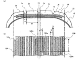
- (A) is the width direction fragmentary sectional view which shows an example of the tire of this invention
- (b) is explanatory drawing which shows the structure of the reinforcement layer of the tire of (a). It is a graph which shows the generation
- FIG. 1 is the width direction fragmentary sectional view which shows an example of the tire of this invention
- (b) is explanatory drawing which shows the structure of the reinforcement layer of the tire of (a). It is a graph which shows the generation
- Fig.1 (a) is a width direction fragmentary sectional view which shows an example of the tire of this invention.
- the tire of the present invention includes three circumferential grooves 1a and 1b and rib-like land portions 2a and 2b in the tread portion 11.
- the circumferential groove means a groove continuous in the tire circumferential direction having a width of about 4 to 18 mm and a depth of about 6 to 10 mm. Accordingly, it is common that three or more tires, usually about 2 to 4 tires, are provided on the tire. By providing the circumferential groove, the occurrence of the hydroplaning phenomenon is suppressed.
- a central circumferential groove (center main groove) is provided on the tire equator plane.
- a rib-shaped land part means the land part pinched
- this rib-shaped land section is provided with a plurality of lateral grooves extending partly or entirely in the tire width direction in order to optimize the hydroplaning water flow and to acquire traction on sandy land, ice and snow. Is common.
- two independent rubber strips 12A and 12B formed by arranging a plurality of cords in parallel and covered with rubber are unwound from two unwinding means arranged at different positions in the tire width direction.
- the circumferential reinforcing layer 12 is formed by spirally winding the outer periphery of the molding drum in the same direction.
- the rubber strips 12A and 12B are wound with a gap in a part or the whole in the tire width direction. That is, in this invention, it has the clearance gap part in which the rubber strip is not wound in at least one part of the tire width direction. Moreover, in the part which does not have a clearance gap, the rubber strip is wound adjacently without overlapping.
- the rubber strips 12A and 12B are wound with no gap in the region overlapping the shoulder-side rib-shaped land portion 2b, and with an equal interval in other regions.
- the outer peripheral surface of the molding drum on which the circumferential reinforcing layer 12 is wound is generally the outer peripheral surface of the carcass layer 13 and the steel belt 14 as tire constituent members that are sequentially stacked on the molding drum. It is. Further, in FIG. 1A, for the sake of simplicity, the circumferential reinforcing layer 12 is continuously described in the tire width direction, and in the drawing, the winding direction is a direction from left to right.
- the end portions 12As, 12Ae, 12Bs, 12Be at the winding start position and the winding end position of the rubber strips 12A, 12B at least the center side end portions 12Ae, 12Bs located on the tire equatorial plane side, It arrange
- the end of the rubber strip is disposed at a position that completely overlaps the rib-like land portion.
- the end of the rubber strip overlaps the maximum width of the opening of the circumferential groove in the entire tire width direction. Means not in the region.
- the width of the rib-like land portion 2a that overlaps the center side end portions 12Ae and 12Bs along the tire width direction is W (mm), and the width of the rubber strips 12A and 12B is G (mm). Then, the values of G and W are set so as to satisfy the relationship of G ⁇ W. Thereby, the reason why the desired effect of the present invention is obtained is as follows. *
- the winding end portion of the rubber strip is at least inside the shoulder side circumferential groove 1b and is likely to be located on the tire equatorial plane CL in many cases.
- this end is located below the circumferential groove, the circumferential rigidity is reduced starting from the end, the strain in the tire circumferential direction is increased, and groove cracks are generated due to this strain,
- it has been found by the inventors' diligent research that the tendency to grow is intensified. This is particularly noticeable in the center region in the tire width direction where distortion is likely to occur due to wiping during traveling, particularly when there are circumferential grooves and winding ends on the tire equator line.
- the tension applied to the rubber strip is larger than when the gap is not opened, and this tendency is particularly great.
- the center side end portions 12Ae and 12Bs of the rubber strip positioned in the center region in the tire width direction are arranged in the region overlapping the rib-like land portion 2a, Since the end of the rubber strip does not exist, it is possible to avoid the influence of excessive distortion due to the rigidity reduction of the end of the rubber strip, and the groove caused by the circumferential reinforcing layer formed by the rubber strip. Generation of cracks can be suppressed.
- all end portions of the rubber strip may be arranged in a region overlapping the rib-like land portion.
- the center side end portion is disposed under the rib-like land portion, the center side end is determined when the gap S between the rubber strip windings or the width G of the rubber strip is larger than the width W of the rib-like land portion. Since the circumferential rigidity of the entire rib-like land portion in which the portion is disposed is reduced, the distortion of the groove adjacent to the rib-like land portion during traveling increases, leading to a groove crack. Therefore, in the present invention, it is assumed that the values of G and W are set so as to satisfy the relationship of G ⁇ W, and the occurrence of distortion is suppressed by positioning the center side end portion under the rib-like land portion. Thus, weight reduction can be achieved without reducing groove crack durability.
- the center side end portions 12Bs and 12Ae of the two rubber strips 12A and 12B are close to each other in the vicinity of the tire equator plane. However, if these end portions are too close to each other, the effect of the end portions of the two rubber strips 12A and 12Ae is received. In some cases, the cracks become worse.
- the distance L in the tire circumferential direction between the center side end portions 12Bs and 12Ae of the two rubber strips is preferably set to 100 to 400 mm.
- the distance L in the tire circumferential direction between the center end portions of the two rubber strips is a rubber measured along the tire circumferential direction regardless of the position in the tire width direction of the center end portion of the rubber strip. It means the distance between the central ends of the strip.
- the center side end portions 12Ae and 12Bs of the two rubber strips 12A and 12B overlap in the tire radial direction.
- the suppression effect of a groove crack can be heightened by pressing the edge part of the rubber strip which is easy to generate
- the center end portions of the rubber strip overlap in the tire radial direction means that the end portion of the rubber strip existing at the winding end position on the tire equatorial plane side in the tire width direction is the tire diameter. It means having an overlap in the direction.
- the circumferential grooves 1a and 1b overlap in the tire radial direction at a position that exists on the tire equator plane or overlaps the central circumferential groove 1a closest to the tire equator plane.
- a region in which each of the two rubber strips 12A, 12B crosses the region overlapping the central circumferential groove 1a across the tire width direction, and the gap between the windings of the rubber strips 12A, 12B overlaps the central circumferential groove 1a It is preferable to wind so that it becomes substantially zero. That is, by winding the adjacent rubber strips in the tire width direction, the circumferential reinforcing layer is substantially spaced as shown in FIG.
- the gap between the rubber strip windings along the tire width direction is S (mm)
- the relationship G> S between the width G of the rubber strip and the gap S of the rubber strip Is preferably satisfied. If the gap S between the rubber strips is larger than the width G of the rubber strip, distortion tends to occur at this portion, which causes a groove crack or the like. By making the gap S between the rubber strips smaller than the width G of the rubber strip, an appropriate rigidity can be ensured.
- the end portions of the two rubber strips are arranged in the central circumferential direction so that the end portions of the two rubber strips are not located in the central circumferential groove 1a.
- the end portion of the rubber strip is arranged in the rib-like land portion 2a adjacent to the central circumferential groove 1a so as not to be positioned in the central circumferential groove 1a, and overlaps the central circumferential groove 1a.
- a rubber strip may not be wound around the position.
- each of the two rubber strips may be folded back on the shoulder side and overlapped in the vicinity of the shoulder-side rib-shaped land portion 2b, thereby further improving high-speed durability. Can do.
- the end portion of the folded rubber strip is arranged in the rib-like land portion 2b, and the end portion of the rubber strip is not arranged in both the central side circumferential groove 1a and the shoulder side circumferential groove 1b.
- the structure is strong against groove cracks.
- the winding region of the rubber strip in the tire width direction is not particularly limited, but preferably, as shown in the drawing, it covers the entire width of the steel belt 14 rather than the width of the steel belt 14. Wind it over a wide area.
- the rubber strip is further wound once more in order to reduce the influence of the end portion of the rubber strip.
- the technique to do is often used.
- the width G of the rubber strip used in the present invention can be appropriately set according to the tire size, the number of rubber strips used for manufacturing, and the like, and is not particularly limited. For example, it is applied by two unwinding means. In this case, the range of 4 to 7 mm is preferable from the viewpoint of the balance between performance and productivity.
- the gap S between the rubber strip windings is effective to be in the range of 30 to 70% with respect to the width of the rubber strip from the viewpoint of reducing weight, ensuring performance, and suppressing air entry in the gap. It is.
- the present invention has been described with respect to the case where a tire is manufactured by applying two independent rubber strips using two unwinding means most suitable from the viewpoint of the productivity of the current production equipment.
- the number of unwinding means is further increased and a plurality of independent rubber strips, for example, 2 to 4 rubber strips, are applied, the same effect can be obtained. That is, in the present invention, the end portion of the circumferential reinforcing layer is not provided under the circumferential groove, and the overlap amount in the circumferential direction between the end portions of the rubber strips is set to the appropriate range described above.
- it is possible to sufficiently exhibit the desired effect of suppressing groove cracks and there is no limitation on this point. For example, even when the main materials of the plurality of rubber strips are different from each other, a sufficient groove crack suppressing effect can be obtained.
- the production efficiency can be improved by winding two independent rubber strips simultaneously by two unwinding means.
- the structure has no end of the circumferential reinforcing layer under the circumferential groove, and the overlap amount in the circumferential direction of the ends of the rubber strips is described above.
- it is possible to sufficiently exhibit the desired effect of suppressing groove cracks, and there is no limitation in this respect as well.
- a sufficient groove crack suppressing effect can be obtained.
- the tire of the present invention can be manufactured by the manufacturing method of the present invention described above, and has a structure that does not have the end portion of the circumferential reinforcing layer under the circumferential groove. It is hard to generate.
- the tire of the present invention is particularly limited with respect to a specific structure other than a point having a circumferential reinforcing layer in which a tread portion has three or more circumferential grooves and a rubber strip is wound spirally. It is not a thing.
- such a tire has a carcass layer composed of one or more carcass plies 13 in which a plurality of reinforcing cords are juxtaposed and embedded in a covering rubber.
- Such a carcass layer normally extends in a toroidal shape between a pair of left and right bead portions, and is wound up and locked around a bead core embedded in each bead portion.
- the circumferential reinforcing layer 12 By arranging the circumferential reinforcing layer 12 on the outer side of the steel belt 14, it is possible to enhance the tagging effect during rotation, and the effect of improving a wide range of performance such as high-speed durability, steering stability, sound / vibration characteristics is obtained. It is done.
- the region in which the circumferential reinforcing layer 12 is disposed in the tire width direction is not particularly limited, but preferably, the steel belt 14 is covered so as to cover the entire width of the steel belt 14 as illustrated. It is arranged in a range wider than the width.
- general-purpose organic fibers such as nylon can be used.
- PEN polyethylene naphthalate
- PET polyethylene terephthalate
- aramid aramid
- a hybrid cord including these can be used.
- the rubber strip was wound with a gap S of 4 mm in the center region in the tire width direction. About the 30 mm width part of the outer side area, it was wound without a gap.
- the outer side in the tire width direction of the center side end portions 12Bs and 12Ae among the ends at the winding start position and the winding end position of the two rubber strips is substantially symmetrical with respect to the tire equatorial plane.
- the center side end portions 12Bs and 12Ae are located at rib-like land portions 2a (width W: 24 mm) that are different in the tire width direction. It was placed in a completely overlapping area.
- the end portions on the center side of the two rubber strips overlap in the tire radial direction, and in the region overlapping the center side circumferential groove (center main groove) 1a, the gap S between the windings of the rubber strips is substantially reduced. It was zero. Further, the distance L in the tire circumferential direction between the center side end portions 12Bs and 12Ae of the two rubber strips was 250 mm.
- the tires from the tire equator plane are substantially symmetrical with respect to the tire equatorial plane with respect to the tire width direction outer sides of the center side end portions 12Bs and 12Ae of the ends at the winding start position and winding end position of the two rubber strips.
- a circumferential reinforcing layer is formed in the same manner as in Example 1 except that the center end portions 12Bs and 12Ae are arranged in a region that completely overlaps the center main groove 1a in the tire width direction, with the width direction distance x being 3 mm. Then, a test tire of Comparative Example 1 was produced.
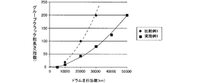
- ⁇ Deteriorated drum test> With respect to the test tires of Example 1 and Comparative Example 1, a deterioration drum test was performed in accordance with the following to evaluate the occurrence of groove cracks when the position of the end of the rubber strip was changed. The result is shown in the graph of FIG. First, each test tire was allowed to deteriorate for 8 weeks in a constant temperature chamber at a temperature of 80 ° C. under O 2 filling conditions. Thereafter, each test tire was assembled on a rim having a rim size of 6.5 J, and a drum test was performed under the conditions of an internal pressure of 230 kPa, a load of 615 kgf, a speed of 60 km / h, and a traveling distance of 50,000 km.
- the crack length of the crack generated in the center main groove for each travel distance was measured for one round of the tire, the sum was calculated, and the sum of the crack lengths during the 20,000 km travel of Comparative Example 1 was calculated.
- the index value is 100. It shows that a groove crack is suppressed, so that a numerical value is small.
- the deformation that causes groove cracks has a maximum value mainly at the ground contact edge (stepping side and kicking side), in addition to those caused by in-cross section distortion caused by wiping deformation in the cross section.
- both deformation factors are added and an initial crack occurs in a relatively short period of time. It has been found that the crack extends at an early stage throughout the central circumferential groove as the core of the crack.
- by winding so that the end of the rubber strip is not disposed in the center main groove it becomes possible to avoid the influence of excessive distortion due to the rigidity reduction of the end of the rubber strip, thereby preventing the groove crack. Is significantly suppressed.
- Examples 2 to 4 Comparative Examples 2 and 3>
- a circumferential reinforcing layer was formed in the same manner as in Example 1, and test tires of Examples 2 to 4 and Comparative Examples 2 and 3 were produced.
- the deterioration drum test was conducted in the same manner as described above, and the degree of occurrence of groove cracks after running 20,000 km was confirmed for each test tire.
- the evaluation was performed based on the total crack length obtained by measuring the length of the crack generated in the central circumferential groove for the entire circumference of the tire. It shows that a groove crack is suppressed, so that a numerical value is small.
- the degree of uneven wear of the rib-like land portion adjacent to the central circumferential groove was evaluated.
- the evaluation was performed by measuring the groove depth of the central circumferential groove at 16 locations on the circumference, and using the PP value. The smaller the value, the lower the tendency for uneven wear.
- the end of the rubber strip is disposed in a region that overlaps the rib-like land portion while avoiding the circumferential groove, and the width W of the rib-like land portion and the width G of the rubber strip are G ⁇ W It was confirmed that the occurrence of groove cracks was effectively suppressed in the test tires of the respective examples satisfying the above relationship while ensuring good uneven wear resistance.
Landscapes
- Engineering & Computer Science (AREA)
- Mechanical Engineering (AREA)
- Tires In General (AREA)
- Tyre Moulding (AREA)
Abstract
螺旋巻きの周方向補強層を有する全てのタイヤにおけるグルーブクラックの発生頻度を抑制するための技術を提供する。 2本のゴムストリップが、タイヤ幅方向の異なる位置から同一方向に螺旋状に巻付けられて形成された周方向補強層を備えるタイヤである。ゴムストリップ12A,12Bがタイヤ幅方向の一部または全体において隙間を空けて配置され、2本のゴムストリップの端部のうち、少なくともタイヤ赤道面側に位置する中央側端部12Bs,12Aeが、タイヤ幅方向においてリブ状陸部2aと完全に重なる位置に配置され、タイヤ幅方向に沿う、中央側端部と重なるリブ状陸部の幅をW、ゴムストリップの幅をGとしたときG<Wの関係を満足する。
Description
本発明はタイヤおよびその製造方法に関し、詳しくは、ゴム被覆されたコードからなるゴムストリップを螺旋状に巻き付けることにより形成され、コード方向が実質的にタイヤ周方向である周方向補強層を備えるタイヤおよびその製造方法の改良に関する。
走行中のタイヤ回転時に発生する、遠心力によるタイヤの膨らみを抑える効果を高めるなどの目的で、タイヤクラウン部に、複数本の補強コードを適宜間隔で並列に引き揃えてゴム中に埋設した帯状ストリップを螺旋状に巻回して、コード方向が実質的にタイヤ周方向となる周方向補強層を設ける技術が汎用されている。この周方向補強層については、軽量化の観点から、帯状ストリップをタイヤ幅方向に間隔を空けて巻回する場合がある(例えば、特許文献1参照)。
ところで、帯状ストリップは、タイヤ周方向に螺旋状に巻回して周方向補強層を形成するものであるため、巻き始めと巻き終わりに必ず端部を有することになるが、この帯状ストリップの端部近傍はその構造上自由端となり、引張り剛性を十分発揮することができず、その結果、局所的に歪が大きくなる。
特に、生産効率の観点から、帯状ストリップの巻出し手段を2箇所設けて、2本の互いに独立した帯状ストリップをタイヤの異なる箇所に同時に巻き付けて、目的領域全体に配設する手法を用いる場合がある。この手法では1箇所で巻き付ける場合と比較して効率的な生産を行うことが可能となり、生産時間やコストを低減できるが、独立した2本の帯状ストリップの端部がタイヤ赤道面近傍に置かれることになり、この端部がセンター主溝に重なった場合には、前述の端部近傍の局所的な歪発生要因により、グルーブクラックを加速させる要因となってしまう。グルーブクラックが発生すると、タイヤの外観や美観が著しく損なわれることに加え、そのまま放置すると、亀裂が進展することで、例えば、溝底の亀裂からタイヤ内部に水が浸入してベルト等の補強材の腐食を引き起こしたりする原因となってくる可能性もある。さらに、帯状ストリップをタイヤ幅方向に間隔を空けて巻回して周方向補強層を形成する場合には、全体の巻き数が減ることで個々の巻位置において帯状ストリップに作用する張力は、間隔を空けない場合と比較して大きくなるため、帯状ストリップの端部における剛性の低下が増大し、局所的な歪発生も一層顕著となる。従って、2本の独立した帯状ストリップを適用し、さらにその帯状ストリップをタイヤ幅方向に適宜間隔を設けて適用しようとする場合には、帯状ストリップの端部の配置の仕方によっては、グルーブクラック発生を助長してしまう可能性がある。
そこで本発明の目的は、上記のような螺旋巻きの周方向補強層を有する全てのタイヤにおけるグルーブクラックの発生頻度を抑制するための技術を提供することにある。
本発明のタイヤは、3本以上の周方向溝と、該周方向溝により画成されたリブ状陸部とを備えるトレッド部と、複数本のコードが並列されてゴム被覆されてなる互いに独立した2本のゴムストリップが、タイヤ幅方向の異なる位置から同一方向に螺旋状に巻付けられて形成された周方向補強層とを備える。前記ゴムストリップは、タイヤ幅方向の一部または全体において隙間を空けて配置される。前記2本のゴムストリップの巻付け開始位置および巻付け終了位置における端部のうち、少なくともタイヤ赤道面側に位置する中央側端部が、タイヤ幅方向において前記リブ状陸部と完全に重なる位置に配置される。前記中央側端部と重なるリブ状陸部のタイヤ幅方向に沿う幅をW(mm)、前記ゴムストリップのタイヤ幅方向に沿う幅をG(mm)としたとき、G<Wの関係を満足することを特徴とする。
また、本発明のタイヤの製造方法は、3本以上の周方向溝と、該周方向溝により画成されたリブ状陸部とを備えるトレッド部を有するタイヤを製造するにあたり、複数本のコードが並列されてゴム被覆されてなる互いに独立した2本のゴムストリップを、タイヤ幅方向の異なる位置に配置された2箇所の巻出し手段から巻き出して、成型ドラムの外周面に同一方向に螺旋状に巻付けることにより周方向補強層を形成する工程を含むタイヤの製造方法であって、前記ゴムストリップの巻付けを、タイヤ幅方向の一部または全体において隙間を空けて行うとともに、前記2本のゴムストリップの巻付け開始位置および巻付け終了位置における端部のうち、少なくともタイヤ赤道面側に位置する中央側端部を、タイヤ幅方向において前記リブ状陸部と完全に重なる位置に配置し、タイヤ幅方向に沿う、前記中央側端部と重なるリブ状陸部の幅をW(mm)、前記ゴムストリップの幅をG(mm)としたときG<Wの関係を満足するようW、Gの値を設定することを特徴とするものである。
本発明によれば、上記構成としたことにより、周方向補強層を有するタイヤにおいて、グルーブクラックの発生頻度を大幅に抑制することができる。
以下、本発明の実施の形態について、図面を参照しつつ詳細に説明する。
図1(a)は、本発明のタイヤの一例を示す幅方向部分断面図である。図示するように、本発明のタイヤは、トレッド部11に、3本の周方向溝1a,1bと、リブ状陸部2a,2bとを備えている。ここで、本発明において周方向溝とは、タイヤの総幅によっても変わるが、幅4~18mm程度、深さ6~10mm程度のタイヤ周方向に連続した溝を意味し、タイヤのトレッド幅に応じて、3本以上、通常は2~4本程度タイヤに設けられることが一般的である。周方向溝を設けることで、ハイドロプレーニング現象の発生が抑制される。特に、小型の乗用車用タイヤでは、3本の周方向溝をタイヤ赤道線に対し対称に配置する場合が多く、この場合は一般に、タイヤ赤道面上に中央側周方向溝(センター主溝)を配置する。前述のワイピング変形の際の溝収縮は一般にタイヤ赤道面において最も大きくなることが知られており、中央側周方向溝は最もグルーブクラックが発生しやすい潜在的な原因を有しているといえる。また、本発明においてリブ状陸部とは、上述の周方向溝によって挟まれた陸部を意味するものである。このリブ状陸部には、多くの場合、ハイドロプレーニングの水流を適正にしたり、砂地や氷雪上でのトラクションを獲得するために、タイヤ幅方向の一部または全体にわたり延びる複数の横溝を設けることが一般的である。
図1(a)は、本発明のタイヤの一例を示す幅方向部分断面図である。図示するように、本発明のタイヤは、トレッド部11に、3本の周方向溝1a,1bと、リブ状陸部2a,2bとを備えている。ここで、本発明において周方向溝とは、タイヤの総幅によっても変わるが、幅4~18mm程度、深さ6~10mm程度のタイヤ周方向に連続した溝を意味し、タイヤのトレッド幅に応じて、3本以上、通常は2~4本程度タイヤに設けられることが一般的である。周方向溝を設けることで、ハイドロプレーニング現象の発生が抑制される。特に、小型の乗用車用タイヤでは、3本の周方向溝をタイヤ赤道線に対し対称に配置する場合が多く、この場合は一般に、タイヤ赤道面上に中央側周方向溝(センター主溝)を配置する。前述のワイピング変形の際の溝収縮は一般にタイヤ赤道面において最も大きくなることが知られており、中央側周方向溝は最もグルーブクラックが発生しやすい潜在的な原因を有しているといえる。また、本発明においてリブ状陸部とは、上述の周方向溝によって挟まれた陸部を意味するものである。このリブ状陸部には、多くの場合、ハイドロプレーニングの水流を適正にしたり、砂地や氷雪上でのトラクションを獲得するために、タイヤ幅方向の一部または全体にわたり延びる複数の横溝を設けることが一般的である。
本発明においては、複数本のコードが並列されてゴム被覆されてなる互いに独立した2本のゴムストリップ12A,12Bを、タイヤ幅方向の異なる位置に配置された2本の巻出し手段から巻き出して、成型ドラムの外周面に同一方向に螺旋状に巻付けることにより周方向補強層12を形成するものである。本発明においては、ゴムストリップ12A,12Bの巻付けを、タイヤ幅方向の一部または全体において隙間を空けて行う。すなわち、本発明においては、タイヤ幅方向の少なくとも一部において、ゴムストリップが巻きつけられていない隙間部分を有する。また、隙間を有しない部分においては、ゴムストリップは、重なりをもたずに隣接して巻付けされている。例えば、図示する例では、ゴムストリップ12A,12Bは、ショルダー側リブ状陸部2bに重なる領域では隙間なく、それ以外の領域では等間隔の隙間を空けて巻き付けられている。なお、本発明において、周方向補強層12を巻付け形成する成型ドラムの外周面とは、通常、成型ドラム上に順次積層配置されたタイヤ構成部材としてのカーカス層13およびスチールベルト14の外周面である。また、図1(a)中では、簡略化のために、周方向補強層12はタイヤ幅方向に連続的に記載しており、図中において巻き付け方向は、左から右に向かう方向である。
本発明においては、ゴムストリップ12A,12Bの巻付け開始位置および巻付け終了位置における端部12As,12Ae,12Bs,12Beのうち、少なくともタイヤ赤道面側に位置する中央側端部12Ae,12Bsを、タイヤ幅方向においてリブ状陸部2aと完全に重なる位置に配置する。ここで、本発明においてゴムストリップの端部をリブ状陸部と完全に重なる位置に配置するとは、ゴムストリップの端部が、タイヤ幅方向全体について、周方向溝の開口部の最大幅に重なる領域内に存在しないことを意味する。また、本発明においては、タイヤ幅方向に沿う、上記中央側端部12Ae,12Bsと重なるリブ状陸部2aの幅をW(mm)、ゴムストリップ12A,12Bの幅をG(mm)としたとき、G<Wの関係を満足するようGおよびWの値を設定する。これにより、本発明の所期の効果が得られる理由は、以下の通りである。
ゴムストリップの巻き出し箇所を2箇所設ける場合、ゴムストリップの巻付け端部は、少なくともショルダー側周方向溝1bよりも内側であって、多くの場合タイヤ赤道面CL上に位置する可能性が高いが、仮にこの端部が周方向溝の下に位置すると、端部を起点として周方向剛性が低下して、タイヤ周方向の歪も大きくなり、この歪に起因してグルーブクラックが発生し、並びに成長する傾向が強まることが、本発明者の鋭意研究によって判った。これは特に、走行時にワイピングによって歪が発生しやすいタイヤ幅方向中央領域において、特には、タイヤ赤道線上に周方向溝および巻付け端部が存在する場合に顕著となる。さらに、前述したように、隙間を開けてゴムストリップを巻回する周方向補強層においては、隙間を開けない場合よりもゴムストリップにかかる張力が大きいため、この傾向が特に大きい。本発明においては、少なくともタイヤ幅方向中央領域に位置するゴムストリップの中央側端部12Ae,12Bsをリブ状陸部2aに重なる領域に配置するものとして、タイヤ幅方向中央領域における周方向溝の下にゴムストリップの端部が存在しないものとしたので、ゴムストリップの端部の剛性低下による過大な歪の影響を回避することが可能となり、ゴムストリップにより形成される周方向補強層に起因するグルーブクラックの発生を抑制することができる。ここで、本発明においては、ゴムストリップの全ての端部をリブ状陸部に重なる領域に配置するものとしてもよいことはいうまでもない。
また、中央側端部をリブ状陸部の下に配置した場合でも、ゴムストリップの巻付け間の隙間Sまたはゴムストリップの幅Gがリブ状陸部の幅Wよりも大きい場合、中央側端部を配置したリブ状陸部全体の周方向剛性が低下してしまうので、走行時に当該リブ状陸部に隣接する溝の歪が大きくなり、グルーブクラックにつながる。よって、本発明では、G<Wの関係を満足するようGおよびWの値を設定するものとして、リブ状陸部の下に中央側端部を位置させることで、歪の発生を抑制して、グルーブクラック耐久性を低下させずに、軽量化についても達成できるものとなった。
また、2本のゴムストリップ12A,12Bの中央側端部12Bs,12Aeはタイヤ赤道面近傍で互いに近接するが、これら端部同士があまり近づきすぎると、相互の端部の効果を受けて、グルーブクラックの悪化が大きくなる場合がある。これに対し、本発明においては、2本のゴムストリップの中央側端部同士の位置をタイヤ周方向においてずらすことで、端部の効果を緩和させて、グルーブクラックの悪化を抑制することが可能となる。本発明においては、具体的には、2本のゴムストリップの中央側端部12Bs,12Ae間のタイヤ周方向における距離Lを、100~400mmとすることが好ましい。2本のゴムストリップの中央側端部間の距離Lが100mm未満では、端部同士が近すぎるためにグルーブクラックの亀裂成長を速める結果となり、顕著なグルーブクラック抑制効果が発現しにくい。一方、2本のゴムストリップの中央側端部間の距離Lが400mmを超えると、タイヤ周方向において2本のゴムストリップの巻付け回数が多くなる部位の剛性が相対的に高まることで、中央側周方向溝1a近傍の陸部の接地圧が周上で不均一となり、早期の偏摩耗の原因となるため好適でない。ここで、2本のゴムストリップの中央側端部間のタイヤ周方向における距離Lとは、ゴムストリップの中央側端部のタイヤ幅方向における位置によらず、タイヤ周方向に沿って測ったゴムストリップの中央側端部同士の間の距離を意味する。
本発明においては、図示するように、2本のゴムストリップ12A,12Bの中央側端部12Ae,12Bs同士を、タイヤ径方向においてもオーバーラップさせることが好ましい。これにより、歪の発生しやすいゴムストリップの端部を端部を持たない他のゴムストリップにより押えることで、グルーブクラックの抑制効果をより高めることができる。ここで、ゴムストリップの中央側端部同士がタイヤ径方向にオーバーラップしているとは、タイヤ幅方向におけるタイヤ赤道面側の巻付け端位置に存在するゴムストリップの端部部分が、タイヤ径方向において重なりを有することを意味する。
さらに、本発明においては、少なくとも、周方向溝1a,1bのうちタイヤ赤道面上に存在するかまたはタイヤ赤道面に最も近い中央側周方向溝1aに重なる位置で、タイヤ径方向においてオーバーラップする2本のゴムストリップ12A,12Bのそれぞれを、中央側周方向溝1aに重なる領域をタイヤ幅方向にわたり横切って、ゴムストリップ12A,12Bの巻付け間の隙間が中央側周方向溝1aに重なる領域において実質的にゼロとなるよう巻付けることが好ましい。すなわち、隣り合うゴムストリップをタイヤ幅方向にずらして巻き付けることで、少なくともタイヤ赤道面近傍に存在する周方向溝に重なる位置においては、図1に示すように、周方向補強層が実質的に隙間なく配設されているものとする。これにより、グルーブクラックの抑制効果をより向上することができる。周方向補強層に重なる位置に隙間が残っていると、ワイピングなどのトレッド変形に対し溝底が変形しやすくなるためである。ここで、図示するように周方向溝がタイヤ赤道面上に存在する場合には、特にワイピングの歪が大きいことから、かかる場合に本発明の効果が顕著に表れるといえる。
さらにまた、本発明においては、タイヤ幅方向に沿う、ゴムストリップの巻付け間の隙間をS(mm)としたとき、ゴムストリップの幅Gとゴムストリップの隙間Sとが、G>Sの関係を満足することが好ましい。ゴムストリップの隙間Sがゴムストリップの幅Gに比して大きいと、この部分で歪が発生しやすくなって、グルーブクラック等の要因となる。ゴムストリップの隙間Sをゴムストリップの幅Gより小さくすることで、適度な剛性を確保することができる。
本発明における具体的なゴムストリップの巻付け形態としては、図1に示すような、2本のゴムストリップの端部が中央側周方向溝1aに位置しないように、端部を中央側周方向溝1aに隣接するリブ状陸部2aと重なるよう配置して、中央側周方向溝1aと重なる位置には独立した2本のゴムストリップの両方が巻き付けられているものとする形態の他、2本のゴムストリップの端部が中央側周方向溝1aに位置しないように、端部を中央側周方向溝1aに隣接するリブ状陸部2aに配置して、中央側周方向溝1aに重なる位置にはゴムストリップを巻付けない形態とすることもできる。この場合、ゴムストリップの端部の剛性低下の影響についてはいずれの形態においても同様に避けることができ、グルーブクラックの抑制に対してはほぼ同等の効果を期待できるが、釘などの貫通に対する中央側周方向溝1aの保護性の点では圧倒的に前者の方が優れるため、パンクしやすい市場では前者の形態が有利である。また、図1に示す形態等において、2本のゴムストリップのそれぞれをショルダー側で折り返してショルダー側リブ状陸部2b近傍で重複させる形態としてもよく、これにより、高速耐久性をより向上させることができる。この場合も、折り返したゴムストリップの端部をリブ状陸部2bに配置して、中央側周方向溝1aおよびショルダー側周方向溝1bの双方にゴムストリップの端部を配置しないものとすることで、グルーブクラックに強い構造となる。ここで、本発明において、タイヤ幅方向におけるゴムストリップの巻付け領域については、特に制限されないが、好適には図示するように、スチールベルト14の全幅を覆うように、スチールベルト14の幅よりも広い範囲に巻付ける。
本発明の製造方法においては、上記条件を満足する点のみが重要であり、それ以外の点については、常法に従い適宜実施することができ、特に制限されるものではない。例えば、ショルダー側リブ状陸部2bに重なる位置のゴムストリップの端部12As,12Beについては、ゴムストリップの端部の影響を緩和するために、その上にさらに1回多くゴムストリップの巻付けを行う手法が用いられる場合が多い。また、ゴムストリップを1回隙間なく周方向補強層の配設領域の全体に巻き付けた後、その上に、図1に示すような部分的に隙間を空けた巻付けを行う場合もあるが、本発明においては、これらいずれの巻付け手法についても、制限なく実施することが可能である。本発明において用いるゴムストリップの幅Gについては、タイヤサイズや製造に使用するゴムストリップの本数等に応じて適宜設定することができ、特に制限はないが、例えば、2箇所の巻出し手段で適用する場合には、性能と生産性とのバランスの点から、4~7mmの範囲が好適である。また、ゴムストリップの巻付け間の隙間Sは、軽量化と性能確保および隙間でのエア入り抑制との両立の観点から、ゴムストリップの幅に対し30~70%の範囲とすることが効果的である。
上記においては、現状の生産設備の生産性の観点から最も好適な2箇所の巻出し手段を用いて、2本の独立したゴムストリップを適用してタイヤを製造する場合に関して本発明を説明したが、本発明においては、さらに巻出し手段の数を増して、独立した複数本、例えば2~4本のゴムストリップを適用する場合においても、同様の効果を得ることができるものである。すなわち、本発明においては、周方向溝の下に周方向補強層の端部を有しない構造とし、かつ、ゴムストリップ同士の端部の周方向におけるオーバーラップ量を上述した適切な範囲とすることで、所望のグルーブクラックの抑制効果を十分に発揮させることが可能となるものであり、この点に関し、何らの制限も有するものではない。例えば、複数のゴムストリップの主たる材質が互いに異なっている場合であっても、十分なグルーブクラック抑制効果を得ることができる。
また、本発明の製造方法においては、2箇所の巻出し手段により、2本の独立したゴムストリップを同時に巻付けることで生産効率を高めることができるが、1箇所の巻出し手段によって、複数の独立したゴムストリップを順番に巻付ける際においても、周方向溝の下に周方向補強層の端部を有しない構造とし、かつ、ゴムストリップ同士の端部の周方向におけるオーバーラップ量を上述した適切な範囲とすることで、所望のグルーブクラックの抑制効果を十分に発揮させることが可能となるものであり、この点に関しても、何らの制限も有しない。上記と同様に、例えば、複数のゴムストリップの主たる材質が互いに異なっている場合であっても、十分なグルーブクラック抑制効果を得ることができる。
本発明のタイヤは、上記本発明の製造方法により製造することができ、周方向溝の下に周方向補強層の端部を有しない構造となっているため、従来と比較して、グルーブクラックを発生しにくいものである。本発明のタイヤは、トレッド部に3本以上の周方向溝を有し、ゴムストリップが螺旋状に巻き付けられてなる周方向補強層を備える点以外の具体的な構造については、特に制限されるものではない。具体的には例えば、かかるタイヤは、複数本の補強コードを並列させて被覆ゴムに埋設してなるカーカスプライ13の1枚以上からなるカーカス層を骨格とする。かかるカーカス層は、通常、左右一対のビード部間にトロイド状に延在し、各ビード部にそれぞれ埋設されたビードコアの周りに巻き上げられて係止される。
カーカス層13のタイヤ半径方向外側には、少なくとも1層で、好適には2層で交錯配置されるスチールベルト14と、1層の周方向補強層12とが、タイヤ半径方向内側から順次配置されている。スチールベルト14の外側に周方向補強層12を配置することで、回転時のタガ効果を高めることができ、高速耐久性や操縦安定性、音/振動特性などの幅広い性能を向上する効果が得られる。ここで、本発明において、タイヤ幅方向における周方向補強層12の配設領域については、特に制限されないが、好適には図示するように、スチールベルト14の全幅を覆うように、スチールベルト14の幅よりも広い範囲に配設する。周方向補強層を構成するコードには、ナイロン等の汎用の有機繊維を用いることができるが、特に、ポリエチレンナフタレート(PEN)、ポリエチレンテレフタレート(PET)、アラミドおよびこれらを含むハイブリッドコード等の高剛性の素材を適用した場合には、低剛性の素材を用いた場合と比較してゴムストリップ端部の剛性低下の程度が大きくなるので、その分、ゴムストリップ端部を周方向溝の下に位置させないことによる効果が高まり、本発明の適用がより有用となる。また、これらの高剛性繊維を用いることで、フラットスポットを低減し、剛性の増大分をコード使用量の削減に結び付けることができるなどの効果も得られ、より優れたタイヤを提供することが可能となる。
以下、本発明を、実施例を用いてより詳細に説明する。
<実施例1>
タイヤサイズ205/55R16にて、図1に示すような、トレッド部に、3本の周方向溝(溝幅w=6mm)と、これらにより画成されたリブ状陸部とを備える乗用車用タイヤの製造を行った。6本のナイロンコードが並列されてゴム被覆されてなる2本のゴムストリップ(幅G=6mm)を、タイヤ幅方向の異なる位置に配置された2本の巻き付けヘッドを有する製造設備を用いて、2本のヘッドから同時に巻き出して、成型ドラムの外周面に同一方向に螺旋状に巻付けることにより周方向補強層を形成した。ゴムストリップの巻付けは、タイヤ幅方向の中央領域において4mmの隙間Sを空けて行った。外側領域の30mm幅の部分については隙間なく巻き付けた。この実施例1において、2本のゴムストリップの巻付け開始位置および巻付け終了位置における端部のうち中央側端部12Bs,12Aeのタイヤ幅方向外側は、タイヤ赤道面を基準としてほぼ対称に、タイヤ赤道面からのタイヤ幅方向距離xで9mmの位置にあり、中央側端部12Bs,12Aeは、図1に示すように、タイヤ幅方向において異なるリブ状陸部2a(幅W:24mm)に完全に重なる領域に配置されていた。また、2本のゴムストリップの中央側端部はタイヤ径方向においてオーバーラップしており、中央側周方向溝(センター主溝)1aに重なる領域では、ゴムストリップの巻付け間の隙間Sが実質的にゼロとなっていた。また、2本のゴムストリップの中央側端部12Bs,12Ae間のタイヤ周方向における距離Lは250mmであった。
<比較例1>
2本のゴムストリップの巻付け開始位置および巻付け終了位置における端部のうち中央側端部12Bs,12Aeのタイヤ幅方向外側を、タイヤ赤道面を基準としてほぼ対称に、タイヤ赤道面からのタイヤ幅方向距離xで3mmの位置とし、中央側端部12Bs,12Aeの全体をタイヤ幅方向においてセンター主溝1aと完全に重なる領域に配置した以外は実施例1と同様にして周方向補強層を形成し、比較例1の供試タイヤを作製した。
2本のゴムストリップの巻付け開始位置および巻付け終了位置における端部のうち中央側端部12Bs,12Aeのタイヤ幅方向外側を、タイヤ赤道面を基準としてほぼ対称に、タイヤ赤道面からのタイヤ幅方向距離xで3mmの位置とし、中央側端部12Bs,12Aeの全体をタイヤ幅方向においてセンター主溝1aと完全に重なる領域に配置した以外は実施例1と同様にして周方向補強層を形成し、比較例1の供試タイヤを作製した。
<劣化ドラム試験>
実施例1および比較例1の供試タイヤにつき、以下に従い劣化ドラム試験を実施して、ゴムストリップの端部の位置を変えた際のグルーブクラックの発生状態を評価した。その結果を、図2のグラフに示す。まず、各供試タイヤを、温度80℃の恒温庫でO2充填条件下にて8週間放置して、劣化させた。その後、各供試タイヤをリムサイズ6.5Jのリムに組み、内圧230kPa,荷重615kgf,速度60km/h,走行距離5万kmの条件下で、ドラム試験を行った。評価は、走行距離ごとにセンター主溝内に発生した亀裂の亀裂長さをタイヤ1周分計測して、その和を算出し、比較例1の2万km走行時における亀裂長さの和を100とする指数値で示した。数値が小さいほど、グルーブクラックが抑制されていることを示す。
実施例1および比較例1の供試タイヤにつき、以下に従い劣化ドラム試験を実施して、ゴムストリップの端部の位置を変えた際のグルーブクラックの発生状態を評価した。その結果を、図2のグラフに示す。まず、各供試タイヤを、温度80℃の恒温庫でO2充填条件下にて8週間放置して、劣化させた。その後、各供試タイヤをリムサイズ6.5Jのリムに組み、内圧230kPa,荷重615kgf,速度60km/h,走行距離5万kmの条件下で、ドラム試験を行った。評価は、走行距離ごとにセンター主溝内に発生した亀裂の亀裂長さをタイヤ1周分計測して、その和を算出し、比較例1の2万km走行時における亀裂長さの和を100とする指数値で示した。数値が小さいほど、グルーブクラックが抑制されていることを示す。
図2のグラフの結果から、センター主溝の下にゴムストリップの端部が位置している比較例1では、センター主溝を避けてリブ状陸部の下にゴムストリップの端部を配置した実施例1と比較して、かなり早い段階からゴムストリップの端部のごく近傍に亀裂が発生していることが確認された。いったん亀裂が発生すると、これを起点にしてタイヤ周方向に亀裂が急激に延伸するため、比較例1では、比較的早くグルーブクラックが発生してしまった。これは、従来知見で判明しているワイピング変形に伴う断面内の歪に加えて、ゴムストリップの剛性段差に起因するタイヤ周方向の歪も発生したことで、タイヤの転動による繰り返し変形により早期にグルーブクラックの初期亀裂が発生し延伸したものであると考えられる。これに対し、実施例1の供試タイヤでは、断面内のワイピング変形が主体となることから特定の初期亀裂が生じ、溝底のゴム全体が均等にかつ穏やかに損傷方向に向かうために、結果的に同じ走行距離で2倍近い亀裂長さの差が生じていることが判る。
上記の結果から、グルーブクラックを引き起こす変形としては、従来判明している断面内のワイピング変形による断面内歪に起因するものに加えて、主に接地端(踏み側および蹴り側)で最大値をとるタイヤ周方向変形の寄与もあり、特に、センター主溝にゴムストリップの端部が配置される構造の場合、双方の変形要因が加算されて、比較的短期間に初期亀裂が発生し、これが亀裂の核となって中央側周方向溝全体に早期に亀裂が延伸してしまうことが判った。これに対し、センター主溝にゴムストリップの端部が配置されないように巻き付けを行うことで、ゴムストリップの端部の剛性低下による過大な歪の影響を回避することが可能となり、これによりグルーブクラックが著しく抑制される。
<実施例2~4,比較例2,3>
中央側端部間のタイヤ周方向距離Lの値を変更するとともに、2本のゴムストリップの中央側端部のタイヤ幅方向外側の、タイヤ赤道面からのタイヤ幅方向距離xを変えた以外は実施例1と同様にして周方向補強層を形成し、実施例2~4,比較例2,3の供試タイヤを作製した。
中央側端部間のタイヤ周方向距離Lの値を変更するとともに、2本のゴムストリップの中央側端部のタイヤ幅方向外側の、タイヤ赤道面からのタイヤ幅方向距離xを変えた以外は実施例1と同様にして周方向補強層を形成し、実施例2~4,比較例2,3の供試タイヤを作製した。
上記と同様にして劣化ドラム試験を実施して、各供試タイヤにつき、2万km走行後のグルーブクラックの発生の程度を確認した。評価は、中央側周方向溝内で発生している亀裂の長さをタイヤ一周分計測した総亀裂長さにより行い、比較例1の総亀裂長さを100とする指数で示した。数値が小さい程、グルーブクラックが抑制されていることを示す。また、同時に、中央側周方向溝に隣接するリブ状陸部の偏摩耗の程度を評価した。評価は、中央側周方向溝の溝深さを周上16か所で計測して、そのP-P値により行い、比較例1のP-P値を100とする指数で示した。数値が小さい程、偏摩耗の傾向が低いことを示す。これらの結果を、下記の表中に併せて示す。

上記表中に示すように、ゴムストリップの端部を、周方向溝を避けてリブ状陸部に重なる領域に配置するとともに、リブ状陸部の幅Wおよびゴムストリップの幅GがG<Wの関係を満足するものとした各実施例の供試タイヤにおいては、良好な耐偏摩耗性を確保しつつ、グルーブクラックの発生が効果的に抑制されていることが確かめられた。
1a,1b 周方向溝、2a,2b リブ状陸部、11 トレッド部、12 周方向補強層、12A,12B ゴムストリップ、12As,12Ae,12Bs,12Be ゴムストリップの端部、13 カーカスプライ、14 スチールベルト
Claims (7)
- 3本以上の周方向溝と、該周方向溝により画成されたリブ状陸部とを備えるトレッド部と、複数本のコードが並列されてゴム被覆されてなる互いに独立した2本のゴムストリップが、タイヤ幅方向の異なる位置から同一方向に螺旋状に巻付けられて形成された周方向補強層とを備えるタイヤであって、
前記ゴムストリップが、タイヤ幅方向の一部または全体において隙間を空けて配置され、
前記2本のゴムストリップの巻付け開始位置および巻付け終了位置における端部のうち、少なくともタイヤ赤道面側に位置する中央側端部が、タイヤ幅方向において前記リブ状陸部と完全に重なる位置に配置され、
タイヤ幅方向に沿う、前記中央側端部と重なるリブ状陸部の幅をW(mm)、前記ゴムストリップの幅をG(mm)としたときG<Wの関係を満足することを特徴とするタイヤ。 - 前記2本のゴムストリップの中央側端部同士が、タイヤ径方向においてオーバーラップしている請求項1記載のタイヤ。
- 前記2本のゴムストリップの中央側端部が、互いに異なる前記リブ状陸部と重なるように配置されている請求項1記載のタイヤ。
- 少なくとも、前記周方向溝のうちタイヤ赤道面上に存在するかまたはタイヤ赤道面に最も近い中央側周方向溝に重なる位置で、タイヤ径方向においてオーバーラップする前記2本のゴムストリップのそれぞれが、前記中央側周方向溝に重なる領域をタイヤ幅方向にわたり横切って、前記ゴムストリップの巻付け間の隙間が該中央側周方向溝に重なる領域において実質的にゼロとなるよう巻付けられている請求項2または3記載のタイヤ。
- タイヤ幅方向に沿う、前記ゴムストリップの巻付け間の隙間をS(mm)としたとき、さらに、G>Sの関係を満足する請求項1~4のうちいずれか一項記載のタイヤ。
- 前記2本のゴムストリップの中央側端部間のタイヤ周方向における距離Lが、100~400mmである請求項1~5のうちいずれか一項記載のタイヤ。
- 3本以上の周方向溝と、該周方向溝により画成されたリブ状陸部とを備えるトレッド部を有するタイヤを製造するにあたり、複数本のコードが並列されてゴム被覆されてなる互いに独立した2本のゴムストリップを、タイヤ幅方向の異なる位置に配置された2箇所の巻出し手段から巻き出して、成型ドラムの外周面に同一方向に螺旋状に巻付けることにより周方向補強層を形成する工程を含むタイヤの製造方法であって、
前記ゴムストリップの巻付けを、タイヤ幅方向の一部または全体において隙間を空けて行うとともに、
前記2本のゴムストリップの巻付け開始位置および巻付け終了位置における端部のうち、少なくともタイヤ赤道面側に位置する中央側端部を、タイヤ幅方向において前記リブ状陸部と完全に重なる位置に配置し、
タイヤ幅方向に沿う、前記中央側端部と重なるリブ状陸部の幅をW(mm)、前記ゴムストリップの幅をG(mm)としたときG<Wの関係を満足するようW、Gの値を設定することを特徴とするタイヤの製造方法。
Priority Applications (1)
| Application Number | Priority Date | Filing Date | Title |
|---|---|---|---|
| RU2015153008A RU2614402C1 (ru) | 2013-05-10 | 2014-04-25 | Шина и способ изготовления шины |
Applications Claiming Priority (2)
| Application Number | Priority Date | Filing Date | Title |
|---|---|---|---|
| JP2013100201A JP5486109B1 (ja) | 2013-05-10 | 2013-05-10 | タイヤおよびその製造方法 |
| JP2013-100201 | 2013-05-10 |
Publications (1)
| Publication Number | Publication Date |
|---|---|
| WO2014181705A1 true WO2014181705A1 (ja) | 2014-11-13 |
Family
ID=50630688
Family Applications (1)
| Application Number | Title | Priority Date | Filing Date |
|---|---|---|---|
| PCT/JP2014/061679 Ceased WO2014181705A1 (ja) | 2013-05-10 | 2014-04-25 | タイヤおよびその製造方法 |
Country Status (6)
| Country | Link |
|---|---|
| US (2) | US9321230B2 (ja) |
| EP (1) | EP2801486B1 (ja) |
| JP (1) | JP5486109B1 (ja) |
| CN (1) | CN104139671B (ja) |
| RU (1) | RU2614402C1 (ja) |
| WO (1) | WO2014181705A1 (ja) |
Cited By (3)
| Publication number | Priority date | Publication date | Assignee | Title |
|---|---|---|---|---|
| WO2018034060A1 (ja) * | 2016-08-17 | 2018-02-22 | 株式会社ブリヂストン | 空気入りタイヤ |
| JP2020203613A (ja) * | 2019-06-18 | 2020-12-24 | 株式会社ブリヂストン | タイヤ |
| US11752801B2 (en) | 2018-09-06 | 2023-09-12 | The Yokohama Rubber Co., Ltd. | Pneumatic tire and method of manufacturing pneumatic tire |
Families Citing this family (11)
| Publication number | Priority date | Publication date | Assignee | Title |
|---|---|---|---|---|
| WO2015063977A1 (ja) * | 2013-10-29 | 2015-05-07 | 株式会社ブリヂストン | タイヤ |
| JP6455442B2 (ja) * | 2013-12-16 | 2019-01-23 | 横浜ゴム株式会社 | 空気入りタイヤおよびその製造方法 |
| JP6030623B2 (ja) * | 2014-11-26 | 2016-11-24 | 住友ゴム工業株式会社 | 空気入りタイヤ |
| DE102015204701A1 (de) * | 2015-03-16 | 2016-09-22 | Continental Reifen Deutschland Gmbh | Verfahren zur Herstellung von Fahrzeugreifen |
| JP6423312B2 (ja) * | 2015-05-25 | 2018-11-14 | 株式会社ブリヂストン | タイヤ用補強部材およびこれを用いたタイヤ |
| JP6523811B2 (ja) * | 2015-06-17 | 2019-06-05 | 株式会社ブリヂストン | タイヤ |
| JP7052463B2 (ja) * | 2018-03-22 | 2022-04-12 | 住友ゴム工業株式会社 | タイヤ |
| JP7155768B2 (ja) * | 2018-09-06 | 2022-10-19 | 横浜ゴム株式会社 | 空気入りタイヤ及び空気入りタイヤの製造方法 |
| JP7306976B2 (ja) * | 2019-12-05 | 2023-07-11 | 株式会社ブリヂストン | 空気入りタイヤ |
| CN114801592B (zh) * | 2022-05-19 | 2024-04-30 | 正新橡胶(中国)有限公司 | 一种载重轮胎 |
| US20260048616A1 (en) * | 2024-08-13 | 2026-02-19 | The Goodyear Tire & Rubber Company | Tire with ply strip belt |
Citations (3)
| Publication number | Priority date | Publication date | Assignee | Title |
|---|---|---|---|---|
| JP2007069408A (ja) * | 2005-09-06 | 2007-03-22 | Toyo Tire & Rubber Co Ltd | 空気入りタイヤの製造方法及び空気入りタイヤ |
| JP2008087608A (ja) * | 2006-10-02 | 2008-04-17 | Bridgestone Corp | 空気入りラジアルタイヤ |
| JP2013028070A (ja) * | 2011-07-28 | 2013-02-07 | Sumitomo Rubber Ind Ltd | 空気入りタイヤの製造方法 |
Family Cites Families (24)
| Publication number | Priority date | Publication date | Assignee | Title |
|---|---|---|---|---|
| DE2744997A1 (de) * | 1977-10-06 | 1979-04-19 | Continental Gummi Werke Ag | Fahrzeugluftreifen mit zwei oder mehreren nebeneinanderliegenden laufbaendern |
| US5076336A (en) * | 1987-08-27 | 1991-12-31 | Bridgestone Corporation | Pneumatic tire with a reinforcing layer formed by spirally hooping two continuous materials |
| US4869307A (en) * | 1988-03-17 | 1989-09-26 | The Goodyear Tire & Rubber Company | Pneumatic tire and method for making same |
| JPH02106409A (ja) * | 1988-10-14 | 1990-04-18 | Bridgestone Corp | 空気入りタイヤ |
| JP2783834B2 (ja) | 1989-03-17 | 1998-08-06 | 株式会社ブリヂストン | 高速走行用空気入りラジアルタイヤ |
| EP0453294B1 (en) * | 1990-04-18 | 1995-07-05 | Sumitomo Rubber Industries Limited | Belted radial tyre for motorcycle and belt making method |
| JPH0415106A (ja) * | 1990-05-02 | 1992-01-20 | Sumitomo Rubber Ind Ltd | ラジアルタイヤ |
| JP2842558B2 (ja) * | 1990-05-02 | 1999-01-06 | 住友ゴム工業 株式会社 | 自動二輪車用ラジアルタイヤ |
| JPH04201553A (ja) * | 1990-11-30 | 1992-07-22 | Ohtsu Tire & Rubber Co Ltd :The | ラジアルタイヤにおける補強キャッププライの成形方法 |
| JPH05254309A (ja) * | 1992-03-16 | 1993-10-05 | Yokohama Rubber Co Ltd:The | タイヤにおける補強材の巻付構造 |
| JP2714341B2 (ja) * | 1993-03-22 | 1998-02-16 | 住友ゴム工業株式会社 | 空気入りタイヤ |
| JP2568062B2 (ja) * | 1995-06-07 | 1996-12-25 | 住友ゴム工業株式会社 | ラジアルタイヤ |
| JP3555809B2 (ja) * | 1995-06-19 | 2004-08-18 | 株式会社ブリヂストン | ラジアルタイヤ |
| JP3814356B2 (ja) * | 1997-01-09 | 2006-08-30 | 横浜ゴム株式会社 | 空気入りラジアルタイヤ |
| JP3158065B2 (ja) * | 1997-01-28 | 2001-04-23 | 住友ゴム工業株式会社 | 自動二輪車用タイヤ |
| JPH11115413A (ja) * | 1997-10-09 | 1999-04-27 | Yokohama Rubber Co Ltd:The | 空気入りタイヤ |
| JP2001322405A (ja) * | 2000-05-12 | 2001-11-20 | Bridgestone Corp | 空気入りラジアルタイヤ |
| JP2002001833A (ja) * | 2000-06-26 | 2002-01-08 | Sumitomo Rubber Ind Ltd | 空気入りタイヤのバンドの形成方法 |
| JP4060173B2 (ja) * | 2002-12-12 | 2008-03-12 | 横浜ゴム株式会社 | 空気入りタイヤ、および空気入りタイヤの製造方法 |
| GB2404636B (en) * | 2003-08-01 | 2006-12-20 | Dunlop Tyres Ltd | Motorcycle radial tyre |
| JP2005247069A (ja) * | 2004-03-02 | 2005-09-15 | Yokohama Rubber Co Ltd:The | 空気入りラジアルタイヤ |
| JP4759922B2 (ja) * | 2004-03-02 | 2011-08-31 | 横浜ゴム株式会社 | 空気入りラジアルタイヤ |
| JP2006130942A (ja) * | 2004-11-02 | 2006-05-25 | Bridgestone Corp | 空気入りラジアルタイヤ |
| US20130284337A1 (en) * | 2012-04-26 | 2013-10-31 | Bernard Jean Francois Croissant | Accordion spiral overlay for a pneumatic tire |
-
2013
- 2013-05-10 JP JP2013100201A patent/JP5486109B1/ja not_active Expired - Fee Related
-
2014
- 2014-04-25 WO PCT/JP2014/061679 patent/WO2014181705A1/ja not_active Ceased
- 2014-04-25 RU RU2015153008A patent/RU2614402C1/ru active
- 2014-05-06 EP EP14167102.4A patent/EP2801486B1/en not_active Not-in-force
- 2014-05-08 US US14/273,172 patent/US9321230B2/en active Active
- 2014-05-09 CN CN201410196210.2A patent/CN104139671B/zh not_active Expired - Fee Related
-
2015
- 2015-07-13 US US14/797,778 patent/US9931800B2/en not_active Expired - Fee Related
Patent Citations (3)
| Publication number | Priority date | Publication date | Assignee | Title |
|---|---|---|---|---|
| JP2007069408A (ja) * | 2005-09-06 | 2007-03-22 | Toyo Tire & Rubber Co Ltd | 空気入りタイヤの製造方法及び空気入りタイヤ |
| JP2008087608A (ja) * | 2006-10-02 | 2008-04-17 | Bridgestone Corp | 空気入りラジアルタイヤ |
| JP2013028070A (ja) * | 2011-07-28 | 2013-02-07 | Sumitomo Rubber Ind Ltd | 空気入りタイヤの製造方法 |
Cited By (9)
| Publication number | Priority date | Publication date | Assignee | Title |
|---|---|---|---|---|
| WO2018034060A1 (ja) * | 2016-08-17 | 2018-02-22 | 株式会社ブリヂストン | 空気入りタイヤ |
| JP2018027746A (ja) * | 2016-08-17 | 2018-02-22 | 株式会社ブリヂストン | 空気入りタイヤ |
| US11273674B2 (en) | 2016-08-17 | 2022-03-15 | Bridgestone Corporation | Pneumatic tire |
| US11752801B2 (en) | 2018-09-06 | 2023-09-12 | The Yokohama Rubber Co., Ltd. | Pneumatic tire and method of manufacturing pneumatic tire |
| JP2020203613A (ja) * | 2019-06-18 | 2020-12-24 | 株式会社ブリヂストン | タイヤ |
| WO2020255919A1 (ja) * | 2019-06-18 | 2020-12-24 | 株式会社ブリヂストン | タイヤ |
| CN113950417A (zh) * | 2019-06-18 | 2022-01-18 | 株式会社普利司通 | 轮胎 |
| CN113950417B (zh) * | 2019-06-18 | 2023-08-25 | 株式会社普利司通 | 轮胎 |
| US11919341B2 (en) | 2019-06-18 | 2024-03-05 | Bridgestone Corporation | Tire |
Also Published As
| Publication number | Publication date |
|---|---|
| JP2014218216A (ja) | 2014-11-20 |
| CN104139671A (zh) | 2014-11-12 |
| CN104139671B (zh) | 2015-10-28 |
| EP2801486A1 (en) | 2014-11-12 |
| RU2614402C1 (ru) | 2017-03-28 |
| US9321230B2 (en) | 2016-04-26 |
| US20150336345A1 (en) | 2015-11-26 |
| JP5486109B1 (ja) | 2014-05-07 |
| US9931800B2 (en) | 2018-04-03 |
| US20140332130A1 (en) | 2014-11-13 |
| EP2801486B1 (en) | 2016-09-14 |
Similar Documents
| Publication | Publication Date | Title |
|---|---|---|
| JP5486109B1 (ja) | タイヤおよびその製造方法 | |
| JP5639415B2 (ja) | 空気入りタイヤ | |
| JP5977566B2 (ja) | 空気入りラジアルタイヤ及び空気入りラジアルタイヤの製造方法 | |
| US8820377B2 (en) | Pneumatic radial tire | |
| CN109982865B (zh) | 航空器用子午线轮胎 | |
| JP2014065438A (ja) | 空気入りタイヤ | |
| CN105793067A (zh) | 充气轮胎及其制造方法 | |
| US10179481B2 (en) | Pneumatic tire | |
| JP2016210389A (ja) | 空気入りタイヤ | |
| JP4205196B2 (ja) | 空気入りラジアルタイヤ | |
| JP5527003B2 (ja) | 空気入りタイヤ | |
| JP2012144025A (ja) | 空気入りタイヤおよび空気入りタイヤにおける周方向ベルト層の形成方法 | |
| JP2012076674A (ja) | 空気入りラジアルタイヤ | |
| JP5150077B2 (ja) | 小型トラック用空気入りラジアルタイヤ | |
| JP2013071368A (ja) | 空気入りタイヤの製造方法、及び空気入りタイヤ | |
| WO2014073303A1 (ja) | 空気入りタイヤ、及びその製造方法 | |
| JP6450111B2 (ja) | 空気入りタイヤ | |
| JP6115267B2 (ja) | 空気入りラジアルタイヤ | |
| US20140020802A1 (en) | Pneumatic vehicle tire | |
| JP6517612B2 (ja) | 空気入りタイヤ | |
| JP6129691B2 (ja) | 空気入りタイヤ | |
| JP2014065437A (ja) | 空気入りタイヤ | |
| KR100913914B1 (ko) | 카카스 레이어 성형방법 | |
| JP2013001275A (ja) | 空気入りラジアルタイヤ | |
| JP6542110B2 (ja) | 空気入りタイヤ |
Legal Events
| Date | Code | Title | Description |
|---|---|---|---|
| 121 | Ep: the epo has been informed by wipo that ep was designated in this application |
Ref document number: 14794823 Country of ref document: EP Kind code of ref document: A1 |
|
| NENP | Non-entry into the national phase |
Ref country code: DE |
|
| ENP | Entry into the national phase |
Ref document number: 2015153008 Country of ref document: RU Kind code of ref document: A |
|
| 122 | Ep: pct application non-entry in european phase |
Ref document number: 14794823 Country of ref document: EP Kind code of ref document: A1 |