WO2014156452A1 - 光学フィルムの製造方法、光学フィルム、面発光体及び光学フィルムの製造装置 - Google Patents
光学フィルムの製造方法、光学フィルム、面発光体及び光学フィルムの製造装置 Download PDFInfo
- Publication number
- WO2014156452A1 WO2014156452A1 PCT/JP2014/054804 JP2014054804W WO2014156452A1 WO 2014156452 A1 WO2014156452 A1 WO 2014156452A1 JP 2014054804 W JP2014054804 W JP 2014054804W WO 2014156452 A1 WO2014156452 A1 WO 2014156452A1
- Authority
- WO
- WIPO (PCT)
- Prior art keywords
- active energy
- energy ray
- curable composition
- optical film
- roll
- Prior art date
Links
Images


Classifications
-
- B—PERFORMING OPERATIONS; TRANSPORTING
- B29—WORKING OF PLASTICS; WORKING OF SUBSTANCES IN A PLASTIC STATE IN GENERAL
- B29C—SHAPING OR JOINING OF PLASTICS; SHAPING OF MATERIAL IN A PLASTIC STATE, NOT OTHERWISE PROVIDED FOR; AFTER-TREATMENT OF THE SHAPED PRODUCTS, e.g. REPAIRING
- B29C41/00—Shaping by coating a mould, core or other substrate, i.e. by depositing material and stripping-off the shaped article; Apparatus therefor
- B29C41/24—Shaping by coating a mould, core or other substrate, i.e. by depositing material and stripping-off the shaped article; Apparatus therefor for making articles of indefinite length
- B29C41/26—Shaping by coating a mould, core or other substrate, i.e. by depositing material and stripping-off the shaped article; Apparatus therefor for making articles of indefinite length by depositing flowable material on a rotating drum
-
- B—PERFORMING OPERATIONS; TRANSPORTING
- B29—WORKING OF PLASTICS; WORKING OF SUBSTANCES IN A PLASTIC STATE IN GENERAL
- B29C—SHAPING OR JOINING OF PLASTICS; SHAPING OF MATERIAL IN A PLASTIC STATE, NOT OTHERWISE PROVIDED FOR; AFTER-TREATMENT OF THE SHAPED PRODUCTS, e.g. REPAIRING
- B29C41/00—Shaping by coating a mould, core or other substrate, i.e. by depositing material and stripping-off the shaped article; Apparatus therefor
- B29C41/24—Shaping by coating a mould, core or other substrate, i.e. by depositing material and stripping-off the shaped article; Apparatus therefor for making articles of indefinite length
- B29C41/28—Shaping by coating a mould, core or other substrate, i.e. by depositing material and stripping-off the shaped article; Apparatus therefor for making articles of indefinite length by depositing flowable material on an endless belt
-
- B—PERFORMING OPERATIONS; TRANSPORTING
- B29—WORKING OF PLASTICS; WORKING OF SUBSTANCES IN A PLASTIC STATE IN GENERAL
- B29D—PRODUCING PARTICULAR ARTICLES FROM PLASTICS OR FROM SUBSTANCES IN A PLASTIC STATE
- B29D11/00—Producing optical elements, e.g. lenses or prisms
- B29D11/00009—Production of simple or compound lenses
- B29D11/00278—Lenticular sheets
- B29D11/00288—Lenticular sheets made by a rotating cylinder
-
- B—PERFORMING OPERATIONS; TRANSPORTING
- B29—WORKING OF PLASTICS; WORKING OF SUBSTANCES IN A PLASTIC STATE IN GENERAL
- B29D—PRODUCING PARTICULAR ARTICLES FROM PLASTICS OR FROM SUBSTANCES IN A PLASTIC STATE
- B29D11/00—Producing optical elements, e.g. lenses or prisms
- B29D11/00009—Production of simple or compound lenses
- B29D11/00365—Production of microlenses
-
- B—PERFORMING OPERATIONS; TRANSPORTING
- B29—WORKING OF PLASTICS; WORKING OF SUBSTANCES IN A PLASTIC STATE IN GENERAL
- B29D—PRODUCING PARTICULAR ARTICLES FROM PLASTICS OR FROM SUBSTANCES IN A PLASTIC STATE
- B29D11/00—Producing optical elements, e.g. lenses or prisms
- B29D11/0074—Production of other optical elements not provided for in B29D11/00009- B29D11/0073
- B29D11/00788—Producing optical films
-
- F—MECHANICAL ENGINEERING; LIGHTING; HEATING; WEAPONS; BLASTING
- F21—LIGHTING
- F21V—FUNCTIONAL FEATURES OR DETAILS OF LIGHTING DEVICES OR SYSTEMS THEREOF; STRUCTURAL COMBINATIONS OF LIGHTING DEVICES WITH OTHER ARTICLES, NOT OTHERWISE PROVIDED FOR
- F21V5/00—Refractors for light sources
- F21V5/002—Refractors for light sources using microoptical elements for redirecting or diffusing light
- F21V5/004—Refractors for light sources using microoptical elements for redirecting or diffusing light using microlenses
-
- G—PHYSICS
- G02—OPTICS
- G02B—OPTICAL ELEMENTS, SYSTEMS OR APPARATUS
- G02B3/00—Simple or compound lenses
- G02B3/0006—Arrays
- G02B3/0012—Arrays characterised by the manufacturing method
- G02B3/0031—Replication or moulding, e.g. hot embossing, UV-casting, injection moulding
-
- B—PERFORMING OPERATIONS; TRANSPORTING
- B29—WORKING OF PLASTICS; WORKING OF SUBSTANCES IN A PLASTIC STATE IN GENERAL
- B29D—PRODUCING PARTICULAR ARTICLES FROM PLASTICS OR FROM SUBSTANCES IN A PLASTIC STATE
- B29D11/00—Producing optical elements, e.g. lenses or prisms
- B29D11/00009—Production of simple or compound lenses
- B29D11/00278—Lenticular sheets
- B29D11/00298—Producing lens arrays
-
- B—PERFORMING OPERATIONS; TRANSPORTING
- B29—WORKING OF PLASTICS; WORKING OF SUBSTANCES IN A PLASTIC STATE IN GENERAL
- B29K—INDEXING SCHEME ASSOCIATED WITH SUBCLASSES B29B, B29C OR B29D, RELATING TO MOULDING MATERIALS OR TO MATERIALS FOR MOULDS, REINFORCEMENTS, FILLERS OR PREFORMED PARTS, e.g. INSERTS
- B29K2105/00—Condition, form or state of moulded material or of the material to be shaped
- B29K2105/0002—Condition, form or state of moulded material or of the material to be shaped monomers or prepolymers
-
- B—PERFORMING OPERATIONS; TRANSPORTING
- B29—WORKING OF PLASTICS; WORKING OF SUBSTANCES IN A PLASTIC STATE IN GENERAL
- B29K—INDEXING SCHEME ASSOCIATED WITH SUBCLASSES B29B, B29C OR B29D, RELATING TO MOULDING MATERIALS OR TO MATERIALS FOR MOULDS, REINFORCEMENTS, FILLERS OR PREFORMED PARTS, e.g. INSERTS
- B29K2105/00—Condition, form or state of moulded material or of the material to be shaped
- B29K2105/0094—Condition, form or state of moulded material or of the material to be shaped having particular viscosity
-
- G—PHYSICS
- G02—OPTICS
- G02B—OPTICAL ELEMENTS, SYSTEMS OR APPARATUS
- G02B3/00—Simple or compound lenses
- G02B3/0006—Arrays
- G02B3/0037—Arrays characterized by the distribution or form of lenses
- G02B3/0043—Inhomogeneous or irregular arrays, e.g. varying shape, size, height
-
- G—PHYSICS
- G02—OPTICS
- G02B—OPTICAL ELEMENTS, SYSTEMS OR APPARATUS
- G02B3/00—Simple or compound lenses
- G02B3/0006—Arrays
- G02B3/0037—Arrays characterized by the distribution or form of lenses
- G02B3/0056—Arrays characterized by the distribution or form of lenses arranged along two different directions in a plane, e.g. honeycomb arrangement of lenses
Definitions
- the present invention relates to a method for manufacturing an optical film in which a plurality of convex microlenses are arranged, an optical film obtained by the manufacturing method, a surface light emitter including the optical film, and an optical in which a plurality of convex microlenses are arranged.
- the present invention relates to a film manufacturing apparatus.
- Organic EL (electroluminescence) light-emitting elements are expected to be used for next-generation illumination that replaces flat panel displays, fluorescent lamps, and the like.
- an organic EL light-emitting element is a laminated body of thin films, and the total reflection angle of light between the thin films is determined by a difference in refractive index between materials of the respective thin films.
- the critical angle ⁇ c is 41.8 °, and light having an incident angle smaller than the critical angle ⁇ c.
- Patent Document 1 and Patent Document 2 propose a method in which an active energy ray-curable composition is directly dropped onto a roll mold, applied to the entire roll mold, and cured. Yes.
- the remaining bubbles in the micro lens of the optical film means that the micro lens has an interface with air, and total reflection of light occurs at the interface according to Snell's law. Therefore, if bubbles remain in the microlens of the optical film, the light extraction efficiency of a surface light emitter formed by providing the optical film on the light emitting surface of a light emitting element such as an organic EL light emitting element is deteriorated. In addition, due to the bubbles in the micro lens of the optical film, an optical film having a desired lens shape cannot be obtained, which becomes a factor of deteriorating the optical characteristics of the optical film exhibited based on the desired lens shape.
- the objective of this invention is providing the manufacturing method of the optical film which suppresses remaining of the bubble in a microlens. Another object of the present invention is to provide an optical film in which the remaining bubbles in the microlens are suppressed. Another object of the present invention is to provide a surface light emitter excellent in light extraction efficiency. Furthermore, the objective of this invention is providing the manufacturing apparatus of the optical film which suppresses the bubble remaining in a microlens.
- the present invention relates to a method for producing an optical film in which a plurality of convex microlenses including the following steps A to F are arranged.
- Step A a step of rotating a roll mold having an outer peripheral surface on which a plurality of concave-shaped microlens transfer portions are arranged, and causing the substrate to travel in the rotation direction of the roll mold along the outer peripheral surface of the roll mold;
- Step B The active energy ray-curable composition ⁇ is supplied onto the coating roll disposed adjacent to the outer peripheral surface of the roll mold, and the active energy ray-curable composition ⁇ is flattened on the coating roll by a flattening means.
- Step C supplying the active energy ray-curable composition ⁇ on the substrate and applying the active energy ray-curable composition ⁇ to the surface of the substrate;
- Step D The active energy ray-curable composition ⁇ applied to the surface of the base material in Step C at the meeting portion of the roll type and the base material, and the outer peripheral surface of the roll type in Step B A step of associating the active energy ray-curable composition ⁇ applied to the surface to form a liquid pool
- Step E State in which the active energy ray-curable composition ⁇ and the active energy ray-curable composition ⁇ associated in the step D are sandwiched between the outer peripheral surface of the roll mold and the surface of the base material And irradiating a region between the outer peripheral surface of the roll mold and the surface of the substrate with active energy rays to cure the active energy ray curable composition ⁇ and the active energy ray curable composition ⁇ .
- this invention relates to the optical film obtained by the manufacturing method of the said optical film. Moreover, this invention relates to the surface light-emitting body containing the said optical film. Furthermore, the present invention provides a roll mold having an outer peripheral surface in which a plurality of concave microlens transfer portions are arranged, A coating roll disposed adjacent to the outer peripheral surface of the roll mold, A first source for supplying an active energy ray-curable composition ⁇ on the coating roll; Planarizing means disposed on the coating roll; A second source for supplying the active energy ray-curable composition ⁇ to the surface of the substrate, The present invention relates to an optical film manufacturing apparatus in which a plurality of convex microlenses are arranged.
- the production method or production apparatus of the present invention it is possible to continuously obtain an optical film in which the remaining bubbles in the microlens are suppressed, and the surface light emitter using the obtained optical film is excellent in light extraction efficiency. .
- a plurality of convex microlenses are arranged.
- FIG. 1 (Convex shape of micro lens) An example of a convex microlens is shown in FIG. 1 in FIG. 1, (a) is a schematic sectional view, and (b) is a schematic perspective view. In FIG. 1, reference numeral 11 indicates a bottom surface portion of the microlens 10.
- the bottom surface portion 11 of the microlens 10 refers to a virtual planar portion surrounded by the outer peripheral edge of the bottom portion of the microlens 10.
- the bottom surface portion of the microlens 10 corresponds to the interface between the microlens 10 and the base layer.
- the longest diameter L of the bottom surface portion 11 of the microlens 10 is the length of the longest portion of the bottom surface portion 11 of the microlens 10, and the average longest diameter L of the bottom surface portion 11 of the microlens 10.
- the surface of the optical film having the microlens 10 was photographed with a scanning microscope, the longest diameter L of the bottom surface portion 11 of the microlens 10 was measured at five locations, and the average value was taken.
- the height H of the microlens 10 refers to the height from the bottom surface 11 of the microlens 10 to the highest portion of the microlens 10, and the average height H ave of the microlens 10 is The cross section of the optical film was photographed with a scanning microscope, and the height H of the microlens 10 was measured at five locations to obtain the average value.
- the convex shape of the microlens 10 includes, for example, a sphere shape, a sphere shape, an ellipsoid sphere shape (a shape obtained by cutting a spheroid on one plane), and an ellipsoid sphere shape (a spheroid).
- Shape cut by two planes parallel to each other pyramid shape, truncated pyramid shape, cone shape, truncated cone shape, and related roof shape (spherical shape, spherical truncated shape, ellipsoidal spherical shape, elliptical shape)
- a body-ball-notch shape, a pyramid shape, a truncated pyramid shape, a cone shape, or a shape in which a truncated cone shape extends along the bottom surface portion for example, a body-ball-notch shape, a pyramid shape, a truncated pyramid shape, a cone shape, or a shape in which a truncated cone shape extends along the bottom surface portion).
- the convex shape of these microlenses 10 may be used alone or in combination of two or more for a plurality of microlenses 10.
- a spherical notch shape, a spherical notch shape, an ellipsoidal spherical notch shape, and an ellipsoidal spherical notch shape are possible.
- a spherical shape and an elliptical spherical shape are more preferable.
- the average longest diameter L ave of the bottom surface portion 11 of the microlens 10 is preferably 2 to 400 ⁇ m, more preferably 10 to 200 ⁇ m, still more preferably 20 to 100 ⁇ m.
- the average longest diameter L ave of the bottom surface portion 11 of the microlens 10 is 2 ⁇ m or more, the light extraction efficiency of the surface light emitter using the optical film is excellent.
- the average longest diameter L ave of the bottom surface portion 11 of the microlens 10 is 400 ⁇ m or less, the microlens is not visually recognized, and the appearance of the optical film is excellent.
- the average height H ave of the microlens 10 is preferably 1 to 200 ⁇ m, more preferably 5 to 100 ⁇ m, still more preferably 10 to 50 ⁇ m.
- the average height H ave of the microlens 10 is 1 ⁇ m or more, the light extraction efficiency of the surface light emitter using the optical film is excellent. Further, when the average height H ave of the microlens 10 is 200 ⁇ m or less, the flexibility of the optical film is excellent.
- the aspect ratio of the microlens 10 is preferably 0.3 to 1.4, more preferably 0.35 to 1.3, and still more preferably 0.4 to 1.0.
- the aspect ratio of the microlens 10 is 0.3 or more, the light extraction efficiency of the surface light emitter using the optical film is excellent.
- the aspect ratio of the microlens 10 is 1.4 or less, a roll-type microlens transfer portion can be easily formed, and an optical film can be easily manufactured.
- the aspect ratio of the microlens 10 was calculated by “average height H ave of microlens 10 / average longest diameter L ave of bottom surface portion 11 of microlens 10”.
- Examples of the shape of the bottom surface portion 11 of the microlens 10 include a circle and an ellipse.
- the shape of the bottom surface portion 11 of these convex microlenses 10 one type may be used alone or two or more types may be used in combination for a plurality of microlenses.
- a circular or elliptical shape is preferable, and a circular shape is more preferable because the light extraction efficiency of a surface light emitter using an optical film is excellent.
- FIG. 2 An example of the optical film 20 viewed from above (that is, the surface side having the microlens 10) is shown in FIG.
- the total ratio of the area of the bottom surface 11 of the microlens 10 (area surrounded by a dotted line in FIG. 2) to the area of the optical film 20 (area surrounded by a solid line in FIG. 2) is preferably 20 to 99%. 30 to 95% is more preferable, and 50 to 93% is still more preferable.
- the ratio of the total area of the bottom surface portion 11 of the microlens 10 to the area of the optical film 20 is 20% or more, the light extraction efficiency of the surface light emitter using the optical film is excellent.
- the ratio of the total area of the bottom surface portion 11 of the microlens 10 to the area of the optical film 20 is 99% or less, a roll-type transfer portion is easily formed, and the optical film can be easily manufactured.
- the maximum value of the ratio of the total area of the bottom surface parts 11 of the microlens 10 to the area of the optical film 20 is about 91%. .
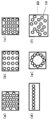
- FIG. 3A An example of the arrangement of the microlenses 10 is shown in FIG.
- FIG. 3B An example of the arrangement of the microlenses 10 is shown in FIG.
- FIG. 3D An example of the arrangement of the microlenses 10.
- a hexagonal arrangement, a rectangular arrangement, and a rhombus arrangement are preferable, and a hexagonal arrangement and a rectangular arrangement are more preferable because of the excellent light extraction efficiency of the surface light emitter using the optical film.
- the production method of the present invention includes the following steps A to F.
- Step A a step of rotating a roll mold having an outer peripheral surface on which a plurality of concave-shaped microlens transfer portions are arranged, and causing the substrate to travel in the rotation direction of the roll mold along the outer peripheral surface of the roll mold;
- Step B The active energy ray-curable composition ⁇ is supplied onto the coating roll disposed adjacent to the outer peripheral surface of the roll mold, and the active energy ray-curable composition ⁇ is flattened on the coating roll by a flattening means.
- Step C supplying the active energy ray-curable composition ⁇ on the substrate and applying the active energy ray-curable composition ⁇ to the surface of the substrate;
- Step D The active energy ray-curable composition ⁇ applied to the surface of the base material in Step C at the meeting portion of the roll type and the base material, and the outer peripheral surface of the roll type in Step B A step of associating the active energy ray-curable composition ⁇ applied to the surface to form a liquid pool
- Step E State in which the active energy ray-curable composition ⁇ and the active energy ray-curable composition ⁇ associated in the step D are sandwiched between the outer peripheral surface of the roll mold and the surface of the base material And irradiating a region between the outer peripheral surface of the roll mold and the surface of the substrate with active energy rays to cure the active energy ray curable composition ⁇ and the active energy ray curable composition ⁇ .
- the manufacturing method including the steps A to F can be performed by using, for example, a manufacturing apparatus shown in FIG. Note that the rotation / running direction of the roll mold 51 and the base material 22 in FIG. 4 is the direction of the arrow in FIG.
- the manufacturing method of the optical film of this invention is demonstrated using the manufacturing apparatus shown in FIG. 4, the manufacturing method of the optical film of this invention is limited to the method using the manufacturing apparatus 50 of the optical film shown in FIG. It is not something.
- Step A drives and rotates a roll mold 51 having an outer peripheral surface on which a plurality of concave microlens transfer portions are arranged, and causes the substrate 22 to travel in the rotational direction of the roll mold 51 along the outer peripheral surface of the roll mold 51. It is a process.
- the base material travels, the base material 22 is pressed against the surface of the roll die 51 by the rotatable nip rolls 55 and 56 disposed in parallel with the roll die adjacent to the outer peripheral surface of the roll die 51. That is, the base material 22 is wound around the nip roll 55, is further wound around the roll mold 51, is further wound around the nip roll 56, and travels in this order.
- Examples of the roll mold 51 include molds such as aluminum, brass, and steel; resin molds such as silicone resin, urethane resin, epoxy resin, ABS resin, fluororesin, and polymethylpentene resin; molds obtained by plating the resin; Examples include a mold made of a material obtained by mixing various metal powders with a resin.
- a die is preferable because of excellent heat resistance and mechanical strength and suitable for continuous production.
- the mold is preferable in many respects such as high durability against polymerization heat generation, difficulty in deformation, scratch resistance, temperature control, and suitable for precision molding.
- the roll mold 51 has a concave transfer portion corresponding to the convex shape.
- the method for producing the transfer portion include cutting with a diamond tool, etching as described in International Publication No. 2008/69324 pamphlet, and the like.
- these methods for producing a transfer portion when forming a concave shape having a curved surface such as a spherical shape, the productivity of the roll mold 51 is excellent, and as described in International Publication No. 2008/69324 pamphlet.
- Etching is preferable, and when a concave shape having no curved surface such as a pyramid shape is formed, cutting with a diamond bit is preferable because the productivity of the roll mold 51 is excellent.
- a manufacturing method of the transfer portion from a master mold having a convex shape obtained by inverting the concave shape of the transfer portion, a metal thin film is produced using an electroforming method, and the metal thin film is wound around a roll core member. A method of manufacturing a cylindrical roll mold can be used.
- the rotational speed of the roll mold 51 that is, the running speed of the outer peripheral surface of the roll mold is preferably 0.1 to 50 m / min, more preferably 0.3 to 40 m / min, because of excellent moldability and productivity of the optical film More preferably, it is 0.5 to 30 m / min.
- step B the active energy ray-curable composition ⁇ is supplied onto the rotatable coating roll 53 that is arranged adjacent to the outer peripheral surface of the roll mold 51 and parallel to the roll mold, and is flattened on the coating roll 53.
- the active energy ray-curable composition ⁇ is flattened by means, and the flattened active energy ray-curable composition ⁇ is applied to the outer peripheral surface of the roll mold 51.
- the flattening means include a doctor blade, an air blade, and an air knife.
- a doctor blade is preferable because it is further flattened.
- the active energy ray-curable composition ⁇ is supplied to the outer peripheral surface of the coating roll 53 from the nozzle 52 functioning as a first supply source, and is flattened by the doctor blade 54 on the coating roll. To be applied.
- the active energy ray-curable composition ⁇ is directly dropped onto the outer peripheral surface of the roll mold 51 and applied, bubbles enter the concave transfer portion of the roll mold 51, and the bubbles remain in the microlens of the optical film. Is difficult to suppress.
- the active energy ray-curable composition ⁇ is once flattened on the coating roll 53 by the doctor blade 54 and then applied to the outer peripheral surface of the roll mold 51, so that the concave transfer portion of the roll mold 51 is applied. Bubbles are prevented from entering, and the remaining of bubbles in the microlens of the optical film is suppressed.
- the nozzle 52 may be singular (one point) or plural, but is preferably singular (one point) because the active energy ray-curable composition ⁇ can be supplied uniformly.
- Examples of the material of the coating roll 53 include metals such as aluminum, stainless steel, and brass; those having a rubber layer on the surface of the metal. Among these coating roll 53 materials, those having a rubber layer on the metal surface are preferable. Examples of the rubber material of the rubber layer include ethylene propylene rubber, butadiene rubber, urethane rubber, nitrile rubber, and silicone rubber. Among these rubber layers, ethylene propylene rubber and silicone rubber are preferable because of excellent resistance to active energy rays.
- the rubber layer on the surface of the coating roll 53 preferably has a rubber hardness specified by JIS-K-6253 of 20 to 90 degrees, more preferably 40 to 85 degrees, and preferably 50 to 80 degrees. Further preferred.
- the rubber hardness of the rubber layer is 20 degrees or more, the remaining of bubbles in the optical film is further suppressed. Further, when the rubber hardness of the rubber layer is 90 degrees or less, distortion applied to the base material 22 is reduced, and damage to the base material 22 is suppressed.
- the coating roll 53 is preferably pressed toward the roll mold 51 because the active energy ray-curable composition ⁇ can be uniformly applied.
- the pressure value to be pressed is preferably 5 to 200 N, and more preferably 10 to 100 N.
- the material of the doctor blade 54 examples include resins such as polyethylene resin, polypropylene resin, and polyester resin; metals such as aluminum and stainless steel.
- a resin is preferable because it is excellent in flexibility and suppresses damage to the coating roll 53, and a polyester resin is particularly preferable.
- the shape of the doctor blade 54 is not particularly limited, and a doctor blade 54 having a known shape can be used.
- the opening width which is the distance between the coating roll 53 and the doctor blade 54, is preferably 0.01 to 0.4 mm, and more preferably 0.02 to 0.3 mm.
- the active energy ray-curable composition ⁇ can be prevented from overflowing too much in the width direction of the roll mold 51.
- the opening width between the coating roll 53 and the doctor blade 54 is 0.4 mm or less, the active energy ray-curable composition ⁇ extends sufficiently in the width direction of the roll mold 51 and bubbles in the microlens of the optical film. Can be further suppressed.
- Step C is a step of supplying the active energy ray-curable composition ⁇ on the substrate 22 and applying the active energy ray-curable composition ⁇ to the surface of the substrate 22.
- the material of the substrate 22 is not particularly limited as long as it is a material that transmits active energy rays.
- acrylic resin, polycarbonate resin, polyester resin, styrene resin, cellulose resin, and imide resin are preferable because of excellent flexibility and active energy ray permeability.
- Acrylic resin, polycarbonate Resins, polyester resins, and imide resins are more preferable.
- the thickness of the substrate 22 is preferably 10 to 500 ⁇ m, more preferably 20 to 400 ⁇ m, and still more preferably 50 to 300 ⁇ m.
- the thickness of the substrate 22 is 10 ⁇ m or more, the handleability of the optical film is excellent.
- the thickness of the base material 22 is 500 ⁇ m or less, the active energy ray-curable composition is excellent in curability, and in the case where an optical film is formed including the base material 22, a surface light emitter using the optical film. The light extraction efficiency is even better.
- the running speed of the base material 22 is preferably 0.1 to 50 m / min, more preferably 0.3 to 40 m / min, and more preferably 0.5 to 30 m / min because of excellent moldability and productivity of the optical film. Further preferred. Since the rotational speed of the roll mold 51 and the traveling speed of the base material 22 are excellent in the moldability of the optical film, it is preferable that the speed is comparable.
- the active energy ray-curable composition ⁇ is supplied from the nozzle 52 ′ and applied to the surface of the substrate 22. At that time, uneven application of the active energy ray-curable composition ⁇ can be reduced, and uneven thickness of the base layer can be suppressed. Therefore, the base 22 is interposed and the nip roll is adjacent to the outer peripheral surface of the nip roll 55.
- the active energy ray-curable composition ⁇ is supplied from a nozzle 52 ′ onto a rotatable coating roll 53 ′ arranged in parallel to the surface of the substrate 22 and flattened by a doctor blade 54 ′ on the coating roll.
- the former method is more preferable in which the active energy ray-curable composition ⁇ is supplied from the nozzle 52 ′ onto the coating roll 53 ′, and is applied to the surface of the substrate 22 after being flattened by the doctor blade 54 ′ on the coating roll.
- the nozzle 52 ' functions as the second supply source
- the nozzle 52', the coating roll 53 ', and the doctor blade 54' function as the second supply source.
- the same material as the coating roll 53 described above can be used for the coating roll 53 ′.
- the coating roll 53 ′ is preferably pressed toward the nip roll 55 because the active energy ray-curable composition ⁇ can be uniformly applied.
- doctor blade 54 can use the same material and shape as the doctor blade 54 described above.
- the opening width which is the distance between the coating roll 53 'and the doctor blade 54', is preferably 0.01 to 0.4 mm, more preferably 0.02 to 0.3 mm.
- the active energy ray-curable composition ⁇ can be prevented from overflowing excessively in the width direction of the substrate 22. .
- the opening width between the coating roll 53 ′ and the doctor blade 54 ′ is 0.4 mm or less, the active energy ray-curable composition ⁇ extends sufficiently in the width direction of the substrate 22 and is inside the microlens of the optical film. The remaining of the bubbles can be further suppressed.
- step D the active energy ray-curable composition ⁇ applied to the surface of the base material 22 in step C and the outer peripheral surface of the roll die 51 in step B at the meeting portion of the roll die 51 and the base material 22.
- This is a step of associating the active energy ray-curable composition ⁇ and forming a liquid pool.
- the active energy ray curable composition ⁇ and the active energy ray curable composition ⁇ may be the same composition or different compositions, and may be appropriately selected according to the use and function of the optical film.
- the active energy ray-curable composition ⁇ and the active energy ray-curable composition ⁇ have the same composition, the microlens 10 and the base layer 21 (see FIG. 5 described later) have the same optical film 20 with the same composition. can get.
- the active energy ray curable composition ⁇ and the active energy ray curable composition ⁇ are different in composition, the cured product of the active energy ray curable composition ⁇ is mainly formed around the microlens 10 in the base layer. An optical film in which a cured product of the active energy ray-curable composition ⁇ is unevenly distributed around 21 is obtained.
- the active energy ray-curable composition ⁇ and the active energy ray-curable composition ⁇ are not particularly limited as long as they can be cured by active energy rays, but the active energy ray-curable composition is excellent in handling property and curability, and the optical film is flexible. Property, heat resistance, scratch resistance, solvent resistance, light transmittance, and other properties, the polymerizable monomer (A), the crosslinkable monomer (B), and the active energy ray polymerization initiator ( An active energy ray-curable composition containing C) is preferred.
- Examples of the polymerizable monomer (A) include methyl (meth) acrylate, ethyl (meth) acrylate, n-propyl (meth) acrylate, iso-propyl (meth) acrylate, n-butyl (meth) acrylate, iso -Butyl (meth) acrylate, sec-butyl (meth) acrylate, tert-butyl (meth) acrylate, n-hexyl (meth) acrylate, cyclohexyl (meth) acrylate, n-octyl (meth) acrylate, 2-ethylhexyl (meth) ) Acrylate, dodecyl (meth) acrylate, tridecyl (meth) acrylate, stearyl (meth) acrylate, alkyl (meth) acrylate, phenyl (meth) acrylate, benzyl (meth
- Epoxy (meth) acrylates aromatic vinyls such as styrene and ⁇ -methylstyrene; vinyl ethers such as vinyl methyl ether, vinyl ethyl ether and 2-hydroxyethyl vinyl ether; vinyl carboxylates such as vinyl acetate and vinyl butyrate; Examples thereof include olefins such as ethylene, propylene, butene and isobutene.
- These polymerizable monomers (A) may be used individually by 1 type, and may use 2 or more types together. Among these polymerizable monomers (A), the handleability and curability of the active energy ray-curable composition are excellent, and the flexibility, heat resistance, scratch resistance, solvent resistance, light transmittance, etc.
- (meth) acrylates, epoxy (meth) acrylates, aromatic vinyls and olefins are preferable, and (meth) acrylates and epoxy (meth) acrylates are more preferable.
- (meth) acrylate refers to acrylate or methacrylate.
- the content of the polymerizable monomer (A) in the active energy ray-curable composition is preferably 0.5 to 60% by mass, more preferably 1 to 57% by mass, based on the total amount of the active energy ray-curable composition. 2 to 55% by mass is more preferable.
- the content of the polymerizable monomer (A) is 0.5% by mass or more, the handleability of the active energy ray-curable composition is excellent, and the substrate adhesion of the optical film is excellent.
- hardenability of an active energy ray curable composition as the content rate of a polymerizable monomer (A) is 60 mass% or less, and it is excellent in the solvent resistance of an optical film.
- crosslinkable monomer (B) examples include hexa (meth) acrylates such as dipentaerythritol hexa (meth) acrylate and caprolactone-modified dipentaerythritol hexa (meth) acrylate; dipentaerythritol hydroxypenta (meth) acrylate , Penta (meth) acrylates such as caprolactone-modified dipentaerythritol hydroxypenta (meth) acrylate; ditrimethylolpropane tetra (meth) acrylate, pentaerythritol tetra (meth) acrylate, pentaerythritol ethoxy modified tetra (meth) acrylate, dipenta Such as erystol hexa (meth) acrylate, dipentaerystol penta (meth) acrylate, tetramethylolmethane
- Tora (meth) acrylates trimethylolpropane tri (meth) acrylate, trisethoxylated trimethylolpropane tri (meth) acrylate, pentaerythritol tri (meth) acrylate, ethoxylated pentaerythritol tri (meth) acrylate, tris ( Tri (meth) acrylates such as 2- (meth) acryloyloxyethyl) isocyanurate, aliphatic hydrocarbon-modified trimethylolpropane tri (meth) acrylate having 2 to 5 carbon atoms, and isocyanuric acid ethylene oxide-modified tri (meth) acrylate Triethylene glycol di (meth) acrylate, diethylene glycol di (meth) acrylate, 1,3-butylene glycol di (meth) acrylate, 1,4-butanediol di (meth) ) Acrylate, 1,5-pentanediol di
- Polyurethane polyfunctional (meth) acrylates such as compounds obtained by reacting an isocyanate group with a hydroxyl group-containing (meth) acrylate; divinyl ethers such as diethylene glycol divinyl ether and triethylene glycol divinyl ether Butadiene, isoprene, dienes such as dimethyl butadiene and the like.
- These crosslinkable monomers (B) may be used individually by 1 type, and may use 2 or more types together.
- the optical film has excellent physical properties such as flexibility, heat resistance, scratch resistance, solvent resistance, and light transmittance.
- (Meth) acrylates, tetra (meth) acrylates, tri (meth) acrylates, di (meth) acrylates, diallyls, allyl (meth) acrylates, polyester di (meth) acrylates, urethane polyfunctional (meth) Acrylates are preferred, hexa (meth) acrylates, penta (meth) acrylates, tetra (meth) acrylates, tri (meth) acrylates, di (meth) acrylates, polyester di (meth) acrylates, urethane Functional (meth) acrylates are more preferred.
- the content of the crosslinkable monomer (B) in the active energy ray curable composition is preferably 30 to 98% by mass, more preferably 35 to 97% by mass, based on the total amount of the active energy ray curable composition. More preferably, it is -96 mass%.
- the content of the crosslinkable monomer (B) is 30% by mass or more, the crosslinkability and curability of the active energy ray-curable composition are excellent, and the solvent resistance of the optical film is excellent.
- flexibility of an optical film is excellent in the content rate of a crosslinkable monomer (B) being 98 mass% or less.
- Examples of the active energy ray polymerization initiator (C) include benzoin, benzoin methyl ether, benzoin ethyl ether, benzoin isopropyl ether, benzoin isobutyl ether, acetoin, benzyl, benzophenone, p-methoxybenzophenone, 2,2-diethoxyacetophenone.
- ⁇ , ⁇ -dimethoxy- ⁇ -phenylacetophenone benzyldimethyl ketal, methylphenylglyoxylate, ethylphenylglyoxylate, 4,4′-bis (dimethylamino) benzophenone, 1-hydroxycyclohexyl phenyl ketone, 2-hydroxy Carbonyl compounds such as -2-methyl-1-phenylpropan-1-one and 2-ethylanthraquinone; tetramethylthiuram monosulfide, tetramethylthiura Sulfur compounds such as disulfide; 2,4,6-trimethylbenzoyl diphenylphosphine oxide, acylphosphine oxide such as benzo dichloride ethoxy phosphine oxide, and the like.
- active energy ray polymerization initiators (C) may be used alone or in combination of two or more.
- active energy ray polymerization initiators (C) carbonyl compounds and acyl phosphine oxides are preferred because they are excellent in handleability and curability of the active energy ray curable composition and light transmittance of the optical film. More preferred are carbonyl compounds.
- the content of the active energy ray polymerization initiator (C) in the active energy ray curable composition is preferably 0.1 to 10% by mass, and preferably 0.5 to 8% by mass, based on the total amount of the active energy ray curable composition. Is more preferable, and 1 to 5% by mass is even more preferable.
- the content of the active energy ray polymerization initiator (C) is 0.1% by mass or more, the handleability and curability of the active energy ray curable composition are excellent.
- the active energy ray curable composition ⁇ and the active energy ray curable composition ⁇ may include fine particles to scatter light, if necessary.
- the fine particles are not particularly limited as long as they have a light diffusion effect in the visible light wavelength region (approximately 400 to 700 nm), and known fine particles can be used.
- the fine particles may be used alone or in combination of two or more.
- the fine particle material examples include gold, silver, silicon, aluminum, magnesium, zirconium, titanium, zinc, germanium, indium, tin, antimony, cerium, and other metals; silicon oxide, aluminum oxide, magnesium oxide, zirconium oxide, and oxide.
- Metal oxides such as titanium, zinc oxide, germanium oxide, indium oxide, tin oxide, indium tin oxide, antimony oxide, and cerium oxide; metal hydroxides such as aluminum hydroxide; metal carbonates such as magnesium carbonate; silicon nitride Metal nitrides such as acrylic resin, styrene resin, silicone resin, urethane resin, melamine resin, epoxy resin and the like. These fine particle materials may be used alone or in combination of two or more.
- silicon, aluminum, magnesium, silicon oxide, aluminum oxide, magnesium oxide, aluminum hydroxide, magnesium carbonate, acrylic resin, styrene resin, silicone Resin, urethane resin, melamine resin, and epoxy resin are preferable, and silicon oxide, aluminum oxide, aluminum hydroxide, magnesium carbonate, acrylic resin, styrene resin, silicone resin, urethane resin, melamine resin, and epoxy resin are more preferable.
- the volume average particle diameter of the fine particles is preferably 0.5 to 20 ⁇ m, more preferably 0.7 to 15 ⁇ m, and still more preferably 0.8 to 10 ⁇ m.
- the volume average particle diameter of the fine particles is 0.5 ⁇ m or more, light in the visible wavelength region can be effectively scattered. Further, when the volume average particle diameter of the fine particles is 20 ⁇ m or less, the fluidity when mixed with the active energy ray-curable composition is excellent.
- Examples of the shape of the fine particles include a spherical shape, a cylindrical shape, a cubic shape, a rectangular parallelepiped shape, a pyramid shape, a conical shape, a star shape, a donut shape, a daisy chain shape, a powder shape, and an indefinite shape. These fine particles may be used singly or in combination of two or more.
- a spherical shape, a cubic shape, a rectangular parallelepiped shape, a pyramid shape, and a star shape are preferable, and a spherical shape is more preferable because light in the visible light wavelength range can be effectively scattered.
- an antifoaming agent if necessary, an antifoaming agent, a release agent, an antistatic agent, a leveling agent, an antifouling property improving agent, a dispersion stabilizer, Other components such as various additives such as a viscosity modifier may be included.
- the viscosity of the active energy ray-curable composition ⁇ and the active energy ray-curable composition ⁇ is preferably 10 to 3000 mPa ⁇ s, more preferably 20 to 2500 mPa ⁇ s, because of excellent handleability during production of the optical film. 30 to 2000 mPa ⁇ s is more preferable.
- the nip roll 55 is preferably pressed against the roll mold 51 with a constant pressure because the thickness of the optical film becomes uniform.
- the pressure value to be pressed is preferably 5 to 200 N, and more preferably 10 to 100 N.
- the active energy ray-curable composition ⁇ applied to the outer peripheral surface of the roll mold 51 in the process B in the process B meets and associates to form a liquid pool.
- the thickness of the base layer 21 can be controlled by the opening width that is the distance between the roll mold 51 and the nip roll 55 and the pressure from the nip roll 55 toward the roll mold 51.
- the base layer 21 mainly has a role of relaxing the stress associated with polymerization shrinkage during curing and maintaining the convex shape of the microlens 10.
- the thickness of the base layer 21 is preferably 1 to 60 ⁇ m, more preferably 3 to 40 ⁇ m, still more preferably 5 to 30 ⁇ m. When the thickness of the base layer 21 is 1 ⁇ m or more, the handleability of the optical film is excellent. Further, when the thickness of the base layer 21 is 60 ⁇ m or less, the light extraction efficiency of the surface light emitter using the optical film is more excellent.
- step E the active energy ray curable composition ⁇ and the active energy ray curable composition ⁇ associated in step D are sandwiched between the outer peripheral surface of the roll mold 51 and the surface of the base material 22.
- This is a step of irradiating an active energy ray to a region between the outer peripheral surface of the roll mold 51 and the surface of the substrate 22 to cure the active energy ray curable composition ⁇ and the active energy ray curable composition ⁇ .
- active energy rays examples include ultraviolet rays, electron beams, X-rays, infrared rays, and visible rays.
- active energy rays examples include ultraviolet rays, electron beams, X-rays, infrared rays, and visible rays.
- ultraviolet rays and electron beams are preferable, and ultraviolet rays are more preferable because the active energy ray-curable composition is excellent in curability and can suppress deterioration of the optical film.
- Step F is a step of peeling the cured product obtained in Step E from the roll mold 51.
- the roll mold 51 is subjected to a peeling treatment, or a release agent is added to the active energy ray curable composition ⁇ and the active energy ray curable composition ⁇ . It may be included.
- the cured product obtained as described above can be used as an optical film in which a plurality of convex microlenses are arranged, and can be suitably used for various uses, particularly for constituting a surface light emitter.
- cured material and the base material 22 joined and integrated may be utilized as an optical film, and the hardened
- the former using an optical film in which the cured product and the base material 22 are bonded and integrated has an advantage that the process is simplified because there is no peeling process of the base material 22 from the viewpoint of the manufacturing method. .
- the surface light emitter of the present invention includes the optical film of the present invention.
- Examples of the surface light emitter of the present invention include a surface light emitter as shown in FIG.
- the surface light emitter shown in FIG. 5 will be described, but the surface light emitter according to the present invention is not limited to the surface light emitter shown in FIG.
- the surface light emitter shown in FIG. 5 is an optical film on the surface of a glass substrate 41 of an organic EL light emitting device 40 in which a glass substrate 41, an anode 42, a light emitting layer 43, and a cathode 44 are sequentially laminated, with an adhesive layer 30 interposed therebetween. 20 is provided.
- the optical film 20 includes a microlens 10 made of an active energy ray-curable composition and a laminate of a base layer 21 and a base material 22.
- the surface light emitter in which the organic EL light emitting device 40 is provided with the optical film 20 of the present invention is excellent in light extraction efficiency.
- a light-shielding sheet having a thickness of 0.1 mm with a hole having a diameter of 10 mm is disposed on the light-emitting surface of the surface light emitters obtained in the examples and comparative examples, and this is used as an integrating sphere (manufactured by Labsphere, size 6). Inch) at the sample opening.
- chromium plating was applied to obtain a roll mold.
- the width of the area where the concave transfer portion is present is 280 mm. This area is arranged in the center of the axial length of the roll mold of 320 mm, and both ends of the roll mold in the axial direction are mirror surface areas. It was.
- Steps A to F were performed by the manufacturing apparatus shown in FIG. 4 to manufacture an optical film.
- a polyester film (trade name “Diafoil T910E125”, manufactured by Mitsubishi Plastics, width 340 mm, thickness 125 ⁇ m) is used as the base material 22, and rubber rollers (product) are used as the coating rolls 53 and 53 ′ and the nip rolls 55 and 56.
- the temperature of the curable composition ⁇ is 60 ° C.
- the viscosity of the active energy ray curable composition ⁇ and the active energy ray curable composition ⁇ is 300 mPa ⁇ s
- 0.9 J / cm 2 from the active energy ray irradiation device 57. was irradiated with ultraviolet rays of the accumulated light quantity.
- Example 1 As an application method of the active energy ray curable composition ⁇ , the active energy ray curable composition ⁇ is supplied onto the coating roll 53, and the active energy ray curable composition ⁇ is flattened on the coating roll 53 by the doctor blade 54.
- a method for applying the active energy ray-curable composition ⁇ a method of applying to the outer peripheral surface of the roll mold 51 is used, and the opening width between the coating roll 53 and the doctor blade 54 is 0.03 mm.
- An optical film was obtained using a method in which the active energy ray-curable composition ⁇ was directly applied onto the substrate 22 and applied without using 53 ′ and the doctor blade 54 ′.
- Examples 2 to 4 An optical film was obtained in the same manner as in Example 1 except that the opening width between the coating roll 53 and the doctor blade 54 was changed as shown in Table 1.
- Example 5 As an application method of the active energy ray-curable composition ⁇ , the same method as in Example 2 was used except that the active energy ray-curable composition ⁇ was supplied onto the substrate 22 and applied by flattening with a bar coater. To obtain an optical film.
- Example 6 As a method of applying the active energy ray curable composition ⁇ , the active energy ray curable composition ⁇ is supplied onto the coating roll 53 ′, and the active energy ray curable composition ⁇ is applied to the doctor blade 54 ′ on the coating roll 53 ′. Using the method of applying on the base material 22 after flattening by the same operation as in Example 2 except that the opening width between the coating roll 53 ′ and the doctor blade 54 ′ is 0.1 mm, An optical film was obtained.
- Example 1 As an application method of the active energy ray-curable composition ⁇ , a method in which the active energy ray-curable composition ⁇ is directly dropped onto the outer peripheral surface of the roll mold 51 without using the coating roll 53 and the doctor blade 54 is used. Were the same as in Example 2 to obtain an optical film.
- Table 1 shows the evaluation of the presence or absence of bubbles in the microlenses of the optical film obtained in Examples 1 to 6 and Comparative Example 1 above. Also, images obtained by photographing the surface of the optical film obtained in Example 2, Example 4 and Comparative Example 1, that is, the surface on which the microlens is formed, with an optical microscope are shown in FIGS.
- Example 2 A surface light emitter was obtained in the same manner as in Example 7 except that the optical film obtained in Example 2 was changed to the optical film obtained in Comparative Example 1.
- Table 2 shows the light extraction efficiency of the obtained surface light emitter.
- Example 7 It was confirmed that the surface light emitter obtained in Example 7 was superior in light extraction efficiency to the surface light emitter obtained in Comparative Example 2.
- the optical film obtained by the production method of the present invention suppresses the remaining bubbles in the microlens, a surface light emitter excellent in light extraction efficiency can be obtained by using this optical film.
- This surface light emitter can be suitably used for lighting, a display, a screen, and the like, for example.
Landscapes
- Engineering & Computer Science (AREA)
- Mechanical Engineering (AREA)
- Manufacturing & Machinery (AREA)
- Health & Medical Sciences (AREA)
- Ophthalmology & Optometry (AREA)
- Physics & Mathematics (AREA)
- General Physics & Mathematics (AREA)
- Optics & Photonics (AREA)
- General Engineering & Computer Science (AREA)
- Casting Or Compression Moulding Of Plastics Or The Like (AREA)
- Application Of Or Painting With Fluid Materials (AREA)
- Non-Portable Lighting Devices Or Systems Thereof (AREA)
- Shaping Of Tube Ends By Bending Or Straightening (AREA)
- Optical Elements Other Than Lenses (AREA)
Abstract
Description
一般に、有機EL発光素子は、薄膜の積層体であり、各薄膜の材料の屈折率の差により、薄膜間での光の全反射角が決まる。現状では、発光層で発生した光の約80%が、有機EL発光素子内部に閉じ込められ、外部に取り出すことができない。具体的には、ガラス基板の屈折率を1.5とし、空気層の屈折率を1.0とすると、臨界角θcは41.8°であり、この臨界角θcよりも小さい入射角の光はガラス基板から空気層へ出射するが、この臨界角θcよりも大きい入射角の光は全反射してガラス基板内部に閉じ込められる。そのため、有機EL発光素子表面のガラス基板内部に閉じ込められた光をガラス基板外部に取り出す、即ち、光取り出し効率を向上させることが要請されている。
また、光学フィルムのマイクロレンズ内の気泡により、所望のレンズ形状の光学フィルムが得られず、所望のレンズ形状に基づき発揮される光学フィルムの光学特性が悪化する要因となる。
また、本発明の目的は、マイクロレンズ内の気泡の残存が抑制された光学フィルムを提供することにある。
また、本発明の目的は、光取り出し効率に優れた面発光体を提供することにある。
更に、本発明の目的は、マイクロレンズ内の気泡の残存を抑制する光学フィルムの製造装置を提供することにある。
工程A:凹形状のマイクロレンズ転写部が複数配置された外周面を有するロール型を回転させ、前記ロール型の外周面に沿って前記ロール型の回転方向に基材を走行させる工程、
工程B:前記ロール型の外周面に隣接して配置されたコーティングロール上に活性エネルギー線硬化性組成物βを供給し、前記コーティングロール上で平坦化手段により前記活性エネルギー線硬化性組成物βを平坦化し、前記ロール型の外周面に平坦化された前記活性エネルギー線硬化性組成物βを塗布する工程、
工程C:前記基材上に活性エネルギー線硬化性組成物αを供給し、前記基材の表面に前記活性エネルギー線硬化性組成物αを塗布する工程、
工程D:前記ロール型と前記基材との会合部にて、前記工程Cで前記基材の表面に塗布された前記活性エネルギー線硬化性組成物α及び前記工程Bで前記ロール型の外周面に塗布された前記活性エネルギー線硬化性組成物βを会合し、液溜りを形成する工程、
工程E:前記ロール型の外周面と前記基材の表面との間に、前記工程Dで会合された前記活性エネルギー線硬化性組成物α及び前記活性エネルギー線硬化性組成物βを挟持した状態で、前記ロール型の外周面と前記基材の表面との間の領域に活性エネルギー線を照射し、前記活性エネルギー線硬化性組成物α及び前記活性エネルギー線硬化性組成物βを硬化する工程、及び、
工程F:前記工程Eで得られた硬化物を前記ロール型から剥離する工程。
また、本発明は、前記光学フィルムを含む面発光体に関する。
更に、本発明は、凹形状のマイクロレンズ転写部が複数配列された外周面を有するロール型と、
前記ロール型の外周面に隣接して配置されたコーティングロールと、
前記コーティングロール上に活性エネルギー線硬化性組成物βを供給する第1の供給源と、
前記コーティングロール上に配置された平坦化手段と、
基材の表面に活性エネルギー線硬化性組成物αを供給する第2の供給源とを有する、
凸形状のマイクロレンズが複数配列された光学フィルムの製造装置に関する。
凸形状のマイクロレンズの一例を図1に示す。図1において、(a)は模式的断面図であり、(b)は模式的斜視図である。図1において、符号11は、マイクロレンズ10の底面部を示す。
また、本明細書において、マイクロレンズ10の底面部11の最長径Lとは、マイクロレンズ10の底面部11における最も長い部分の長さをいい、マイクロレンズ10の底面部11の平均最長径Laveは、光学フィルムのマイクロレンズ10を有する表面を走査型顕微鏡にて撮影し、マイクロレンズ10の底面部11の最長径Lを5箇所測定し、その平均値とした。
また、本明細書において、マイクロレンズ10の高さHとは、マイクロレンズ10の底面部11からマイクロレンズ10の最も高い部位までの高さをいい、マイクロレンズ10の平均高さHaveは、光学フィルムの断面を走査型顕微鏡にて撮影し、マイクロレンズ10の高さHを5箇所測定し、その平均値とした。
尚、マイクロレンズ10のアスペクト比は、「マイクロレンズ10の平均高さHave/マイクロレンズ10の底面部11の平均最長径Lave」で算出した。
マイクロレンズ10の底面部11の形状としては、例えば、円形、楕円形等が挙げられる。これらの凸形状のマイクロレンズ10の底面部11の形状は、複数のマイクロレンズにつき、1種を単独で用いてもよく、2種以上を併用してもよい。これらのマイクロレンズ10の底面部11の形状の中でも、光学フィルムを用いた面発光体の光取り出し効率に優れることから、円形、楕円形が好ましく、円形がより好ましい。
光学フィルム20の面積(図2の実線で囲まれた面積)に対するマイクロレンズ10の底面部11の面積(図2の点線で囲まれた面積)の合計の割合は、20~99%が好ましく、30~95%がより好ましく、50~93%が更に好ましい。光学フィルム20の面積に対するマイクロレンズ10の底面部11の面積の合計の割合が20%以上であると、光学フィルムを用いた面発光体の光取り出し効率に優れる。また、光学フィルム20の面積に対するマイクロレンズ10の底面部11の面積の合計の割合が99%以下であると、ロール型の転写部が形成しやすく、光学フィルムの製造が容易となる。
尚、マイクロレンズ10の底面部11がすべて同一の大きさの円形である場合、光学フィルム20の面積に対するマイクロレンズ10の底面部11の合計の面積の割合の最大値は、91%程度となる。
マイクロレンズ10の配列例を、図3に示す。
マイクロレンズ10の配列としては、例えば、六方配列(図3(a))、矩形配列(図3(b))、菱形配列(図3(c))、直線状配列(図3(d))、円状配列(図3(e))、ランダム配列(図3(f))等が挙げられる。これらのマイクロレンズ10の配列の中でも、光学フィルムを用いた面発光体の光取り出し効率に優れることから、六方配列、矩形配列、菱形配列が好ましく、六方配列、矩形配列がより好ましい。
工程A:凹形状のマイクロレンズ転写部が複数配置された外周面を有するロール型を回転させ、前記ロール型の外周面に沿って前記ロール型の回転方向に基材を走行させる工程、
工程B:前記ロール型の外周面に隣接して配置されたコーティングロール上に活性エネルギー線硬化性組成物βを供給し、前記コーティングロール上で平坦化手段により前記活性エネルギー線硬化性組成物βを平坦化し、前記ロール型の外周面に平坦化された前記活性エネルギー線硬化性組成物βを塗布する工程、
工程C:前記基材上に活性エネルギー線硬化性組成物αを供給し、前記基材の表面に前記活性エネルギー線硬化性組成物αを塗布する工程、
工程D:前記ロール型と前記基材との会合部にて、前記工程Cで前記基材の表面に塗布された前記活性エネルギー線硬化性組成物α及び前記工程Bで前記ロール型の外周面に塗布された前記活性エネルギー線硬化性組成物βを会合し、液溜りを形成する工程、
工程E:前記ロール型の外周面と前記基材の表面との間に、前記工程Dで会合された前記活性エネルギー線硬化性組成物α及び前記活性エネルギー線硬化性組成物βを挟持した状態で、前記ロール型の外周面と前記基材の表面との間の領域に活性エネルギー線を照射し、前記活性エネルギー線硬化性組成物α及び前記活性エネルギー線硬化性組成物βを硬化する工程、及び、
工程F:前記工程Eで得られた硬化物を前記ロール型から剥離する工程。
以下、図4に示す製造装置を用いて本発明の光学フィルムの製造方法について説明するが、本発明の光学フィルムの製造方法は図4に示す光学フィルムの製造装置50を用いた方法に限定されるものではない。
工程Aは、凹形状のマイクロレンズ転写部が複数配置された外周面を有するロール型51を駆動回転させ、ロール型51の外周面に沿ってロール型51の回転方向に基材22を走行させる工程である。この基材走行に際しては、ロール型51の外周面に隣接して該ロール型と平行に配置された回転自在なニップロール55,56により、基材22がロール型51の表面に押圧される。即ち、基材22は、ニップロール55に巻き掛けられ、更にロール型51に巻き掛けられ、更にニップロール56に巻き掛けられて、この順に走行する。
転写部の製造方法としては、例えば、ダイヤモンドバイトによる切削、国際公開第2008/69324号パンフレットに記載されるようなエッチング等が挙げられる。これらの転写部の製造方法の中でも、球欠形状等の曲面を有する凹形状を形成する場合、ロール型51の生産性に優れることから、国際公開第2008/69324号パンフレットに記載されるようなエッチングが好ましく、角錐形状等の曲面を有さない凹形状を形成する場合、ロール型51の生産性に優れることから、ダイヤモンドバイトによる切削が好ましい。
また、転写部の製造方法として、転写部の凹形状を反転させた凸形状を有するマスター型から、電鋳法を用いて金属薄膜を作製し、この金属薄膜をロール芯部材に巻きつけて、円筒形のロール型を製造する方法を用いることができる。
工程Bは、ロール型51の外周面に隣接して該ロール型と平行に配置された回転自在なコーティングロール53上に活性エネルギー線硬化性組成物βを供給し、コーティングロール53上で平坦化手段により活性エネルギー線硬化性組成物βを平坦化し、ロール型51の外周面に平坦化された活性エネルギー線硬化性組成物βを塗布する工程である。
活性エネルギー線硬化性組成物βは、第1の供給源として機能するノズル52よりコーティングロール53の外周面に供給され、該コーティングロール上でドクターブレード54により平坦化され、ロール型51の外周面に塗布される。
活性エネルギー線硬化性組成物βを直接ロール型51の外周面に滴下し塗布する方法を用いると、ロール型51の凹形状の転写部内に気泡が入り込み、光学フィルムのマイクロレンズ内の気泡の残存を抑制することが困難である。これに対して、活性エネルギー線硬化性組成物βを一度コーティングロール53上でドクターブレード54により平坦化した後にロール型51の外周面に塗布することで、ロール型51の凹形状の転写部内に気泡が入り込むことが抑制され、光学フィルムのマイクロレンズ内の気泡の残存が抑制される。
ゴム層のゴムの材料としては、例えば、エチレンプロピレンゴム、ブタジエンゴム、ウレタンゴム、ニトリルゴム、シリコーンゴムが挙げられる。これらのゴム層のゴムの材料の中でも、活性エネルギー線への耐性に優れることから、エチレンプロピレンゴム、シリコーンゴムが好ましい。
コーティングロール53の表面のゴム層は、JIS-K-6253で規定するゴム硬度が20~90度であることが好ましく、40~85度であることがより好ましく、50~80度であることが更に好ましい。ゴム層のゴム硬度が20度以上であると、光学フィルム内の気泡の残存がより一層抑制される。また、ゴム層のゴム硬度が90度以下であると、基材22にかかる歪みが小さくなり、基材22の破損が抑制される。
ドクターブレード54の形状は、特に限定されることはなく、公知の形状のドクターブレード54を用いることができる。
工程Cは、基材22上に活性エネルギー線硬化性組成物αを供給し、基材22の表面に活性エネルギー線硬化性組成物αを塗布する工程である。
ロール型51の回転速度と基材22の走行速度とは、光学フィルムの成形性に優れることから、同程度の速度であることが好ましい。
工程Dは、ロール型51と基材22との会合部にて、工程Cで基材22の表面に塗布された活性エネルギー線硬化性組成物α及び工程Bでロール型51の外周面に塗布された活性エネルギー線硬化性組成物βを会合し、液溜りを形成する工程である。
活性エネルギー線硬化性組成物αと活性エネルギー線硬化性組成物βとで組成が同一の場合には、マイクロレンズ10及びベース層21(後述の図5参照)が同一の組成の光学フィルム20が得られる。一方、活性エネルギー線硬化性組成物αと活性エネルギー線硬化性組成物βとで組成が異なる場合には、マイクロレンズ10付近を中心に活性エネルギー線硬化性組成物βの硬化物が、ベース層21付近を中心に活性エネルギー線硬化性組成物αの硬化物が偏在したような光学フィルムが得られる。
本明細書において、(メタ)アクリレートとは、アクリレート又はメタクリレートをいう。
微粒子は、可視光波長域(概ね400~700nm)の光拡散効果を有する微粒子であれば特に限定されることはなく、公知の微粒子を用いることができる。微粒子は、1種を単独で用いてもよく、2種以上を併用してもよい。
ロール型51と基材22との会合部、即ち、基材22がニップロール55とロール型51とにより挟まれる部分にて、工程Cで基材22の表面に塗布された活性エネルギー線硬化性組成物αと工程Bでロール型51の外周面に塗布された活性エネルギー線硬化性組成物βとが出会って会合され、液溜りが形成される。この際の会合の程度は、気泡の発生が抑制されることから、活性エネルギー線硬化性組成物βと活性エネルギー線硬化性組成物αとの質量比がβ:α=5~50:50~95であることが好ましく、β:α=10~40:60~90であることがより好ましい。
ベース層21は、主として、硬化時の重合収縮等に伴う応力を緩和して、マイクロレンズ10の凸形状を維持する役割を有する。
ベース層21の厚さは、1~60μmが好ましく、3~40μmがより好ましく、5~30μmが更に好ましい。ベース層21の厚さが1μm以上であると、光学フィルムの取り扱い性に優れる。また、ベース層21の厚さが60μm以下であると、光学フィルムを用いた面発光体の光取り出し効率により優れる。
工程Eは、ロール型51の外周面と基材22の表面との間に、工程Dで会合された活性エネルギー線硬化性組成物α及び活性エネルギー線硬化性組成物βを挟持した状態で、ロール型51の外周面と基材22の表面との間の領域に活性エネルギー線を照射し、活性エネルギー線硬化性組成物α及び活性エネルギー線硬化性組成物βを硬化する工程である。
工程Fは、工程Eで得られた硬化物をロール型51から剥離する工程である。
工程Fにおいてロール型51から硬化物を剥離しやすくするために、ロール型51に剥離処理を施したり、活性エネルギー線硬化性組成物α及び活性エネルギー線硬化性組成物β中に離型剤を含ませてもよい。
硬化物と基材22とが接合一体化されたものを光学フィルムとして利用する前者の方が、製造方法上の観点から基材22の剥離工程が無いため工程が簡略化されるという利点がある。
本発明の面発光体は、本発明の光学フィルムを含む。
本発明の面発光体としては、例えば、図5に示すような面発光体が挙げられる。
以下、図5に示す面発光体について説明するが、本発明による面発光体は、図5に示す面発光体に限定されるものではない。
有機EL発光素子40に本発明の光学フィルム20を設けた面発光体は、光取り出し効率に優れる。
尚、実施例中の「部」及び「%」は、それぞれ「質量部」及び「質量%」を示す。
実施例及び比較例で得られた光学フィルムのマイクロレンズを有する面を、光学顕微鏡(機種名「VHX-900」、(株)キーエンス製)にて観察し、以下の基準で評価を行った。
A:全体的に気泡の残存が認められない
B:部分的に気泡の残存が認められる
C:全体的に気泡の残存が認められる
実施例及び比較例で得られた面発光体の発光面上に、直径10mmの穴の空いた厚さ0.1mmの遮光シートを配置し、これを、積分球(ラブスフェア社製、大きさ6インチ)のサンプル開口部に配置した。この状態で、面発光体を構成する有機EL発光素子に10mAの電流を通電して点灯した時の、遮光シートの直径10mmの穴から出射する光を、分光計測器(分光器:機種名「PMA-12」(浜松ホトニクス(株)製)、ソフトウェア:ソフト名「PMA用基本ソフトウェアU6039-01ver.3.3.1」)にて測定し、標準視感度曲線による補正を行って、面発光体の光子数を算出した。
光学フィルム無しで得られた面発光体の光子数を100%としたときの、実施例及び比較例で得られた面発光体の光子数の割合を、光取り出し効率とした。
ガラス製のフラスコに、ヘキサメチレンジイソシアネート117.6g(0.7モル)及びイソシアヌレート型のヘキサメチレンジイソシアネート3量体151.2g(0.3モル)、水酸基含有(メタ)アクリレートとして2-ヒドロキシプロピルアクリレート128.7g(0.99モル)及びペンタエリスリトールトリアクリレート693g(1.54モル)、触媒としてジラウリル酸ジ-n-ブチルスズ22.1g、並びに重合禁止剤としてハイドロキノンモノメチルエーテル0.55gを仕込み、75℃に昇温し、75℃に保ったまま攪拌を続け、フラスコ内の残存イソシアネート化合物の濃度が0.1モル/L以下になるまで反応させ、室温に冷却し、ウレタン多官能アクリレートを得た。
得られたウレタン多官能アクリレート34.6部、ポリブチレングリコールジメタクリレート(商品名「アクリエステルPBOM」、三菱レイヨン(株)製)24.7部、エチレンオキサイド変性ビスフェノールAジメタクリレート(商品名「ニューフロンティアBPEM-10」、第一工業製薬(株)製)39.5部及び1-ヒドロキシシクロヘキシルフェニルケトン(商品名「イルガキュア184」、チバ・スペシャルティ・ケミカルズ(株)製)1.2部を混合し、活性エネルギー線硬化性樹脂組成物を得た。
得られた活性エネルギー線硬化性樹脂組成物を、活性エネルギー線硬化性組成物α及び活性エネルギー線硬化性組成物βとして用いた。
外径200mm、軸方向の長さ320mmの鋼製ロールの外周面に、厚さ200μm、ビッカース硬度230Hvの銅めっきを施した。銅めっき層の表面に感光剤を塗布し、レーザ露光、現像及びエッチングを行い、銅めっき層に直径50μm、深さ25μmの半球の凹形状が最小間隔3μmで六方配列に並んでいる転写部が形成された型を得た。得られた型の表面に、防錆性及び耐久性を付与するため、クロムめっきを施し、ロール型を得た。
尚、ロール型における、凹形状の転写部が存在する領域の幅は280mmであり、この領域はロール型の軸方向の長さ320mmの中央に配置され、ロール型の軸方向の両端は鏡面領域とした。
前述した活性エネルギー線硬化性組成物及び前述したロール型を用い、図4に示す製造装置により工程A~Fを実行して、光学フィルムを製造した。
尚、基材22としてポリエステルフィルム(商品名「ダイヤホイルT910E125」、三菱樹脂(株)製、幅340mm、厚さ125μm)を用い、コーティングロール53及び53’並びにニップロール55及び56としてゴムローラー(商品名「グランポールUV」、宮川ローラー(株)製、表面のゴム硬度60度)を用い、ドクターブレード54及び54’としてプラスチックドクターブレード(商品名「マニベール」、(株)エコーブレード製、厚さ0.35mm、刃先形状テーパ状)を用い、活性エネルギー線照射装置57として紫外線照射装置(機種名「Light Hammer 6」、フュージョンUVシステムズ社製)を用いた。
基材22の走行速度を3m/分とし、ロール型51の外周面の走行速度を3m/分とし、ロール型51の表面温度を60℃とし、活性エネルギー線硬化性組成物α及び活性エネルギー線硬化性組成物βの温度を60℃とし、活性エネルギー線硬化性組成物α及び活性エネルギー線硬化性組成物βの粘度を300mPa・sとし、活性エネルギー線照射装置57から0.9J/cm2の積算光量の紫外線を照射した。
活性エネルギー線硬化性組成物βの塗布方法として、コーティングロール53上に活性エネルギー線硬化性組成物βを供給し、この活性エネルギー線硬化性組成物βをコーティングロール53上でドクターブレード54により平坦化した後にロール型51の外周面に塗布する方法を用い、コーティングロール53とドクターブレード54との間の開口幅を0.03mmとし、活性エネルギー線硬化性組成物αの塗布方法として、コーティングロール53’及びドクターブレード54’を用いずに活性エネルギー線硬化性組成物αを直接基材22上に供給して塗布する方法を用い、光学フィルムを得た。
コーティングロール53とドクターブレード54との間の開口幅を表1のように変更した以外は、実施例1と同様に操作を行い、光学フィルムを得た。
活性エネルギー線硬化性組成物αの塗布方法として、基材22上に活性エネルギー線硬化性組成物αを供給し、バーコーターで平坦化して塗布する方法を用いた以外は、実施例2と同様に操作を行い、光学フィルムを得た。
活性エネルギー線硬化性組成物αの塗布方法として、コーティングロール53’上に活性エネルギー線硬化性組成物αを供給し、活性エネルギー線硬化性組成物αをコーティングロール53’上でドクターブレード54’により平坦化した後に基材22上に塗布する方法を用い、コーティングロール53’とドクターブレード54’との間の開口幅を0.1mmとした以外は、実施例2と同様に操作を行い、光学フィルムを得た。
活性エネルギー線硬化性組成物βの塗布方法として、コーティングロール53及びドクターブレード54を用いずに活性エネルギー線硬化性組成物βを直接ロール型51の外周面に滴下し塗布する方法を用いた以外は、実施例2と同様に操作を行い、光学フィルムを得た。

有機EL発光素子(コニカミノルタ社製の白色OLEDデバイス「Symfos OLED-010K」の光出射面(発光面)側の表面の光学フィルムを剥離したもの)の光出射面側に、粘着層(屈折率1.52の屈折液、カーギル社製)を塗布し、実施例2で得られた光学フィルムの基材の面を光学密着させ、面発光体を得た。
実施例2で得られた光学フィルムを比較例1で得られた光学フィルムに変更した以外は、実施例7と同様に操作を行い、面発光体を得た。

11 底面部
20 光学フィルム
21 ベース層
22 基材
30 粘着層
40 有機EL発光素子
41 ガラス基板
42 陽極
43 発光層
44 陰極
50 光学フィルムの製造装置
51 ロール型
52 ノズル
52’ ノズル
53 コーティングロール
53’ コーティングロール
54 ドクターブレード
54’ ドクターブレード
55 ニップロール
56 ニップロール
57 活性エネルギー線照射装置
Claims (10)
- 下記工程A~Fを含む、凸形状のマイクロレンズが複数配置された光学フィルムの製造方法:
工程A:凹形状のマイクロレンズ転写部が複数配置された外周面を有するロール型を回転させ、前記ロール型の外周面に沿って前記ロール型の回転方向に基材を走行させる工程、
工程B:前記ロール型の外周面に隣接して配置されたコーティングロール上に活性エネルギー線硬化性組成物βを供給し、前記コーティングロール上で平坦化手段により前記活性エネルギー線硬化性組成物βを平坦化し、前記ロール型の外周面に平坦化された前記活性エネルギー線硬化性組成物βを塗布する工程、
工程C:前記基材上に活性エネルギー線硬化性組成物αを供給し、前記基材の表面に前記活性エネルギー線硬化性組成物αを塗布する工程、
工程D:前記ロール型と前記基材との会合部にて、前記工程Cで前記基材の表面に塗布された前記活性エネルギー線硬化性組成物α及び前記工程Bで前記ロール型の外周面に塗布された前記活性エネルギー線硬化性組成物βを会合し、液溜りを形成する工程、
工程E:前記ロール型の外周面と前記基材の表面との間に、前記工程Dで会合された前記活性エネルギー線硬化性組成物α及び前記活性エネルギー線硬化性組成物βを挟持した状態で、前記ロール型の外周面と前記基材の表面との間の領域に活性エネルギー線を照射し、前記活性エネルギー線硬化性組成物α及び前記活性エネルギー線硬化性組成物βを硬化する工程、及び、
工程F:前記工程Eで得られた硬化物を前記ロール型から剥離する工程。 - 前記工程Bにおいて、前記コーティングロールにより前記ロール型に5~200Nの圧力で押圧する、請求項1に記載の光学フィルムの製造方法。
- 前記工程Bにおいて、前記コーティングロールと前記平坦化手段との間の開口幅を0.01~0.4mmの範囲内に維持する、請求項1又は2に記載の光学フィルムの製造方法。
- 前記工程Cにおいて、前記活性エネルギー線硬化性組成物αを供給した後に前記活性エネルギー線硬化性組成物αを平坦化する、請求項1~3のいずれかに記載の光学フィルムの製造方法。
- マイクロレンズの凸形状が、球欠形状、球欠台形状、楕円体球欠形状、楕円体球欠台形状、角錐形状、角錐台形状、円錐形状及び円錐台形状の少なくとも1種である、請求項1~4のいずれかに記載の光学フィルムの製造方法。
- 活性エネルギー線硬化性組成物βの粘度が、10~3000mPa・sである、請求項1~5のいずれかに記載の光学フィルムの製造方法。
- 活性エネルギー線硬化性組成物αの粘度が、10~3000mPa・sである、請求項1~6のいずれかに記載の光学フィルムの製造方法。
- 請求項1~7のいずれかに記載の光学フィルムの製造方法により得られる光学フィルム。
- 請求項8に記載の光学フィルムを含む面発光体。
- 凹形状のマイクロレンズ転写部が複数配列された外周面を有するロール型と、
前記ロール型の外周面に隣接して配置されたコーティングロールと、
前記コーティングロール上に活性エネルギー線硬化性組成物βを供給する第1の供給源と、
前記コーティングロール上に配置された平坦化手段と、
基材の表面に活性エネルギー線硬化性組成物αを供給する第2の供給源とを有する、
凸形状のマイクロレンズが複数配列された光学フィルムの製造装置。
Priority Applications (5)
| Application Number | Priority Date | Filing Date | Title |
|---|---|---|---|
| CN201480030332.2A CN105247390B (zh) | 2013-03-28 | 2014-02-27 | 光学膜的制造方法、光学膜、面发光体以及光学膜的制造装置 |
| EP14776045.8A EP2980610B1 (en) | 2013-03-28 | 2014-02-27 | Optical film production method and optical film production device |
| KR1020157030937A KR102156013B1 (ko) | 2013-03-28 | 2014-02-27 | 광학 필름의 제조 방법, 광학 필름, 면발광체 및 광학 필름의 제조 장치 |
| JP2014513379A JP6402625B2 (ja) | 2013-03-28 | 2014-02-27 | 光学フィルムの製造方法、光学フィルム、面発光体及び光学フィルムの製造装置 |
| US14/779,619 US10174905B2 (en) | 2013-03-28 | 2014-02-27 | Optical film production method, optical film, surface light-emitting body and optical film production device |
Applications Claiming Priority (2)
| Application Number | Priority Date | Filing Date | Title |
|---|---|---|---|
| JP2013068515 | 2013-03-28 | ||
| JP2013-068515 | 2013-03-28 |
Publications (1)
| Publication Number | Publication Date |
|---|---|
| WO2014156452A1 true WO2014156452A1 (ja) | 2014-10-02 |
Family
ID=51623446
Family Applications (1)
| Application Number | Title | Priority Date | Filing Date |
|---|---|---|---|
| PCT/JP2014/054804 WO2014156452A1 (ja) | 2013-03-28 | 2014-02-27 | 光学フィルムの製造方法、光学フィルム、面発光体及び光学フィルムの製造装置 |
Country Status (7)
| Country | Link |
|---|---|
| US (1) | US10174905B2 (ja) |
| EP (1) | EP2980610B1 (ja) |
| JP (1) | JP6402625B2 (ja) |
| KR (1) | KR102156013B1 (ja) |
| CN (1) | CN105247390B (ja) |
| TW (1) | TWI601632B (ja) |
| WO (1) | WO2014156452A1 (ja) |
Cited By (1)
| Publication number | Priority date | Publication date | Assignee | Title |
|---|---|---|---|---|
| JP2017039262A (ja) * | 2015-08-20 | 2017-02-23 | 東芝機械株式会社 | 導電性材料・微細構造体付き物品の製造装置および導電性材料・微細構造体付き物品の製造方法 |
Families Citing this family (2)
| Publication number | Priority date | Publication date | Assignee | Title |
|---|---|---|---|---|
| CN108602239B (zh) * | 2016-01-18 | 2020-06-02 | 东丽株式会社 | 表面结构膜的制造方法及制造装置 |
| CN112691558B (zh) * | 2020-12-02 | 2023-03-28 | 江西省纳米技术研究院 | 膜材料的制备方法及系统 |
Citations (10)
| Publication number | Priority date | Publication date | Assignee | Title |
|---|---|---|---|---|
| JPH0732476A (ja) * | 1993-07-23 | 1995-02-03 | Dainippon Printing Co Ltd | 凹凸フィルムの製造装置 |
| WO1998023978A1 (fr) | 1996-11-27 | 1998-06-04 | Dai Nippon Printing Co., Ltd. | Procede de fabrication de feuille de lentille et d'ecran de projection |
| JPH11156869A (ja) * | 1997-12-01 | 1999-06-15 | Kuraray Co Ltd | 表面凹凸部品の製造方法 |
| JP2001062853A (ja) * | 1999-08-27 | 2001-03-13 | Kuraray Co Ltd | 表面凹凸部品の製造方法 |
| JP2003305736A (ja) * | 2002-04-17 | 2003-10-28 | Toppan Printing Co Ltd | 光学物品の製造方法およびマイクロレンズアレイシート |
| JP2004249655A (ja) * | 2003-02-21 | 2004-09-09 | Toppan Printing Co Ltd | 微細凹凸形状を有するシ−トの製造方法 |
| WO2006041089A1 (ja) * | 2004-10-15 | 2006-04-20 | Mitsubishi Rayon Co., Ltd. | 活性エネルギー線硬化性樹脂組成物およびシート状光学物品 |
| JP2007168094A (ja) * | 2005-12-19 | 2007-07-05 | Yasui Seiki:Kk | エンボス造形装置 |
| JP2008058494A (ja) | 2006-08-30 | 2008-03-13 | Hitachi Maxell Ltd | マイクロレンズアレイシートの製造方法 |
| WO2008069324A1 (ja) | 2006-12-08 | 2008-06-12 | Mitsubishi Rayon Co., Ltd., | 光拡散性光学フィルム及びその製造方法、プリズムシート、並びに面光源装置 |
Family Cites Families (17)
| Publication number | Priority date | Publication date | Assignee | Title |
|---|---|---|---|---|
| US6503564B1 (en) * | 1999-02-26 | 2003-01-07 | 3M Innovative Properties Company | Method of coating microstructured substrates with polymeric layer(s), allowing preservation of surface feature profile |
| KR20050117554A (ko) * | 2003-03-13 | 2005-12-14 | 쓰리엠 이노베이티브 프로퍼티즈 캄파니 | 혼성 웹 및 클로져 시스템 |
| CN1805906A (zh) * | 2003-04-14 | 2006-07-19 | 国家制图公司 | 选择性图像部上形成的光栅影像 |
| JP2005070744A (ja) * | 2003-08-05 | 2005-03-17 | Konica Minolta Opto Inc | 光学フィルム、光学フィルムの製造方法、偏光板及び表示装置 |
| JP4438355B2 (ja) * | 2003-09-01 | 2010-03-24 | オムロン株式会社 | マイクロ凹凸パターンを有する樹脂薄膜を備えた光学素子の製造方法 |
| AU2005232074A1 (en) * | 2004-03-29 | 2005-10-20 | LumaChip, Inc. | Roll-to-roll fabricated light sheet and encapsulated semiconductor circuit devices |
| KR20070055510A (ko) * | 2004-08-24 | 2007-05-30 | 후지필름 가부시키가이샤 | 수지 시트 제조방법 |
| JP5061425B2 (ja) * | 2005-05-13 | 2012-10-31 | 凸版印刷株式会社 | 光学部品用金型の製造装置 |
| US20100028554A1 (en) * | 2005-09-20 | 2010-02-04 | Fujifilm Corporation | Method for manufacturing embossed sheet and apparatus therefore, method for manufacturing patterned sheet, and patterned sheet |
| WO2007034981A1 (en) * | 2005-09-22 | 2007-03-29 | Fujifilm Corporation | Method and apparatus for producing embossed sheet |
| JP2007261207A (ja) * | 2006-03-29 | 2007-10-11 | Fujifilm Corp | 凹凸状シートの製造方法 |
| JP2008003234A (ja) * | 2006-06-21 | 2008-01-10 | Fujifilm Corp | 光学シート及びその製造方法 |
| KR20090069184A (ko) * | 2006-10-31 | 2009-06-29 | 미츠비시 레이온 가부시키가이샤 | 렌즈 시트 제조 방법 및 장치 |
| WO2009006252A1 (en) * | 2007-07-03 | 2009-01-08 | 3M Innovative Properties Company | Method of forming composite optical film |
| SE535467C2 (sv) * | 2010-02-19 | 2012-08-21 | Rolling Optics Ab | Förfarande för tryckning av produktkännetecken på ett substratark |
| US9463601B2 (en) * | 2011-05-31 | 2016-10-11 | 3M Innovative Properties Company | Cube corner sheeting having optically variable marking |
| SE537104C2 (sv) * | 2012-11-02 | 2015-01-07 | Rolling Optics Ab | Höghastighetstillverkning av tryckta produktmikrokännemärken |
-
2014
- 2014-02-27 EP EP14776045.8A patent/EP2980610B1/en active Active
- 2014-02-27 CN CN201480030332.2A patent/CN105247390B/zh active Active
- 2014-02-27 KR KR1020157030937A patent/KR102156013B1/ko active IP Right Grant
- 2014-02-27 WO PCT/JP2014/054804 patent/WO2014156452A1/ja active Application Filing
- 2014-02-27 US US14/779,619 patent/US10174905B2/en active Active
- 2014-02-27 JP JP2014513379A patent/JP6402625B2/ja active Active
- 2014-03-04 TW TW103107121A patent/TWI601632B/zh active
Patent Citations (10)
| Publication number | Priority date | Publication date | Assignee | Title |
|---|---|---|---|---|
| JPH0732476A (ja) * | 1993-07-23 | 1995-02-03 | Dainippon Printing Co Ltd | 凹凸フィルムの製造装置 |
| WO1998023978A1 (fr) | 1996-11-27 | 1998-06-04 | Dai Nippon Printing Co., Ltd. | Procede de fabrication de feuille de lentille et d'ecran de projection |
| JPH11156869A (ja) * | 1997-12-01 | 1999-06-15 | Kuraray Co Ltd | 表面凹凸部品の製造方法 |
| JP2001062853A (ja) * | 1999-08-27 | 2001-03-13 | Kuraray Co Ltd | 表面凹凸部品の製造方法 |
| JP2003305736A (ja) * | 2002-04-17 | 2003-10-28 | Toppan Printing Co Ltd | 光学物品の製造方法およびマイクロレンズアレイシート |
| JP2004249655A (ja) * | 2003-02-21 | 2004-09-09 | Toppan Printing Co Ltd | 微細凹凸形状を有するシ−トの製造方法 |
| WO2006041089A1 (ja) * | 2004-10-15 | 2006-04-20 | Mitsubishi Rayon Co., Ltd. | 活性エネルギー線硬化性樹脂組成物およびシート状光学物品 |
| JP2007168094A (ja) * | 2005-12-19 | 2007-07-05 | Yasui Seiki:Kk | エンボス造形装置 |
| JP2008058494A (ja) | 2006-08-30 | 2008-03-13 | Hitachi Maxell Ltd | マイクロレンズアレイシートの製造方法 |
| WO2008069324A1 (ja) | 2006-12-08 | 2008-06-12 | Mitsubishi Rayon Co., Ltd., | 光拡散性光学フィルム及びその製造方法、プリズムシート、並びに面光源装置 |
Non-Patent Citations (1)
| Title |
|---|
| See also references of EP2980610A4 * |
Cited By (1)
| Publication number | Priority date | Publication date | Assignee | Title |
|---|---|---|---|---|
| JP2017039262A (ja) * | 2015-08-20 | 2017-02-23 | 東芝機械株式会社 | 導電性材料・微細構造体付き物品の製造装置および導電性材料・微細構造体付き物品の製造方法 |
Also Published As
| Publication number | Publication date |
|---|---|
| JPWO2014156452A1 (ja) | 2017-02-16 |
| TWI601632B (zh) | 2017-10-11 |
| US20160061407A1 (en) | 2016-03-03 |
| EP2980610B1 (en) | 2019-04-17 |
| CN105247390A (zh) | 2016-01-13 |
| KR20150136522A (ko) | 2015-12-07 |
| CN105247390B (zh) | 2018-01-09 |
| JP6402625B2 (ja) | 2018-10-10 |
| TW201441023A (zh) | 2014-11-01 |
| KR102156013B1 (ko) | 2020-09-15 |
| EP2980610A1 (en) | 2016-02-03 |
| EP2980610A4 (en) | 2016-11-16 |
| US10174905B2 (en) | 2019-01-08 |
Similar Documents
| Publication | Publication Date | Title |
|---|---|---|
| JP5474263B1 (ja) | El素子用光取り出しフィルム、面発光体及びel素子用光取り出しフィルムの製造方法 | |
| WO2013080794A1 (ja) | 光学フィルム、面発光体及び光学フィルムの製造方法 | |
| WO2014157379A1 (ja) | 光学フィルム、光学フィルムの製造方法及び面発光体 | |
| TWI632062B (zh) | El用光提取膜、el用光提取膜的製造方法以及面發光體 | |
| WO2014163135A1 (ja) | 光学フィルム及び面発光体 | |
| JP5998600B2 (ja) | 光学フィルム及びそれを用いた光学装置 | |
| JP6402625B2 (ja) | 光学フィルムの製造方法、光学フィルム、面発光体及び光学フィルムの製造装置 | |
| JP2017191190A (ja) | 光学フィルムの製造方法 | |
| JP6394309B2 (ja) | 光学フィルムの製造方法、光学フィルム及び面発光体 | |
| JP2015206957A (ja) | 光学フィルム、積層体、照明及びディスプレイ | |
| JP2014102370A (ja) | 光学フィルム及び面発光体 | |
| JP2016018024A (ja) | 光学フィルム、面発光体及び光学フィルムの製造方法 | |
| JP2016081614A (ja) | El素子用光取り出しフィルム及び面発光体 | |
| JP2017069208A (ja) | エレクトロルミネッセンス素子用光取り出し構造体及び面発光体 | |
| JP2015219332A (ja) | 光学フィルム及び面発光体 | |
| JP2016018050A (ja) | 光学フィルム、面発光体及び光学フィルムの製造方法 | |
| JP2016045386A (ja) | 光学フィルム、面発光体及び光学フィルムの製造方法 | |
| JP2016143612A (ja) | エレクトロルミネッセンス素子用光取り出しフィルム及び面発光体 | |
| JP2016001207A (ja) | 光学フィルム、面発光体及び光学フィルムの製造方法 | |
| JP2015159033A (ja) | 光取り出しフィルム、面発光体及び光取り出しフィルムの製造方法 | |
| JP2016061813A (ja) | 光学フィルム、面発光体、及び光学フィルムの製造方法 | |
| JP2017191694A (ja) | 光取出し構造体 | |
| JP2017049533A (ja) | エレクトロルミネッセンス素子用光取り出しフィルムおよび面発光体 |
Legal Events
| Date | Code | Title | Description |
|---|---|---|---|
| ENP | Entry into the national phase |
Ref document number: 2014513379 Country of ref document: JP Kind code of ref document: A |
|
| 121 | Ep: the epo has been informed by wipo that ep was designated in this application |
Ref document number: 14776045 Country of ref document: EP Kind code of ref document: A1 |
|
| WWE | Wipo information: entry into national phase |
Ref document number: 14779619 Country of ref document: US |
|
| NENP | Non-entry into the national phase |
Ref country code: DE |
|
| WWE | Wipo information: entry into national phase |
Ref document number: 2014776045 Country of ref document: EP |
|
| ENP | Entry into the national phase |
Ref document number: 20157030937 Country of ref document: KR Kind code of ref document: A |