WO2014155564A1 - 車両の操舵制御装置 - Google Patents
車両の操舵制御装置 Download PDFInfo
- Publication number
- WO2014155564A1 WO2014155564A1 PCT/JP2013/059018 JP2013059018W WO2014155564A1 WO 2014155564 A1 WO2014155564 A1 WO 2014155564A1 JP 2013059018 W JP2013059018 W JP 2013059018W WO 2014155564 A1 WO2014155564 A1 WO 2014155564A1
- Authority
- WO
- WIPO (PCT)
- Prior art keywords
- steering
- vehicle
- steering angle
- angle
- vehicle speed
- Prior art date
- Legal status (The legal status is an assumption and is not a legal conclusion. Google has not performed a legal analysis and makes no representation as to the accuracy of the status listed.)
- Ceased
Links
Images









Classifications
-
- B—PERFORMING OPERATIONS; TRANSPORTING
- B62—LAND VEHICLES FOR TRAVELLING OTHERWISE THAN ON RAILS
- B62D—MOTOR VEHICLES; TRAILERS
- B62D7/00—Steering linkage; Stub axles or their mountings
- B62D7/06—Steering linkage; Stub axles or their mountings for individually-pivoted wheels, e.g. on king-pins
- B62D7/14—Steering linkage; Stub axles or their mountings for individually-pivoted wheels, e.g. on king-pins the pivotal axes being situated in more than one plane transverse to the longitudinal centre line of the vehicle, e.g. all-wheel steering
- B62D7/15—Steering linkage; Stub axles or their mountings for individually-pivoted wheels, e.g. on king-pins the pivotal axes being situated in more than one plane transverse to the longitudinal centre line of the vehicle, e.g. all-wheel steering characterised by means varying the ratio between the steering angles of the steered wheels
- B62D7/159—Steering linkage; Stub axles or their mountings for individually-pivoted wheels, e.g. on king-pins the pivotal axes being situated in more than one plane transverse to the longitudinal centre line of the vehicle, e.g. all-wheel steering characterised by means varying the ratio between the steering angles of the steered wheels characterised by computing methods or stabilisation processes or systems, e.g. responding to yaw rate, lateral wind, load, road condition
-
- B—PERFORMING OPERATIONS; TRANSPORTING
- B62—LAND VEHICLES FOR TRAVELLING OTHERWISE THAN ON RAILS
- B62D—MOTOR VEHICLES; TRAILERS
- B62D6/00—Arrangements for automatically controlling steering depending on driving conditions sensed and responded to, e.g. control circuits
-
- B—PERFORMING OPERATIONS; TRANSPORTING
- B62—LAND VEHICLES FOR TRAVELLING OTHERWISE THAN ON RAILS
- B62D—MOTOR VEHICLES; TRAILERS
- B62D6/00—Arrangements for automatically controlling steering depending on driving conditions sensed and responded to, e.g. control circuits
- B62D6/002—Arrangements for automatically controlling steering depending on driving conditions sensed and responded to, e.g. control circuits computing target steering angles for front or rear wheels
-
- B—PERFORMING OPERATIONS; TRANSPORTING
- B62—LAND VEHICLES FOR TRAVELLING OTHERWISE THAN ON RAILS
- B62D—MOTOR VEHICLES; TRAILERS
- B62D6/00—Arrangements for automatically controlling steering depending on driving conditions sensed and responded to, e.g. control circuits
- B62D6/002—Arrangements for automatically controlling steering depending on driving conditions sensed and responded to, e.g. control circuits computing target steering angles for front or rear wheels
- B62D6/006—Arrangements for automatically controlling steering depending on driving conditions sensed and responded to, e.g. control circuits computing target steering angles for front or rear wheels using a measured or estimated road friction coefficient
Definitions
- the present invention relates to a vehicle steering control device, and more particularly to a vehicle steering control device having a rear wheel steering device capable of steering a rear wheel regardless of a driver's steering operation.
- the rear wheel is steered by the rear wheel steering device as necessary, so that the turning performance of the vehicle is improved as compared with the case where the rear wheel is not steered.
- Steering control is performed.
- the rear wheels are steered in the opposite phase to the front wheels in the low vehicle speed range, and steered in the same phase as the front wheels in the high vehicle speed range, thereby increasing the vehicle speed. Accordingly, the turning response of the vehicle is variably controlled.
- the slip angle of the vehicle is 0 or a small value in order to ensure good steering stability of the vehicle when the vehicle travels at medium and high speeds.
- the vehicle slip angle to the inside of the turn is smaller than the steering angle. Therefore, the vehicle occupant feels that the turning ability of the vehicle is reduced and the vehicle body is facing outward.
- the appropriate value of the vehicle slip angle for the sensation of the vehicle occupant varies not only with the vehicle speed, but also with the size of the steering angle, particularly when the vehicle travels at medium to high speed.
- the slip angle of the vehicle when the vehicle travels at medium to high speed is related to the magnitude of the steering angle. Therefore, it cannot be controlled to an appropriate value for the experience of the vehicle occupant.
- the steering amount of the rear wheel in the same phase as the front wheel is reduced in order to reduce the possibility that the vehicle occupant will feel a decrease in the turning ability of the vehicle when the vehicle is traveling at medium to high speed, The turning responsiveness is not sufficiently lowered and the steering stability of the vehicle cannot be improved effectively.
- Patent Document 2 when it is determined that the ratio of the slip angle to the lateral acceleration is large based on the ratio of the lateral acceleration and the steering angle of the vehicle and the ratio of the slip angle and the lateral acceleration of the vehicle.
- a steering control device for increasing the equivalent cornering power of the rear wheels is described. However, even with this steering control device, the above-mentioned problems cannot be solved.
- the present invention has been made in view of the above-described problems in a conventional steering control device for a vehicle having a rear wheel steering device.
- the main problem of the present invention is to control the slip angle of the vehicle when the vehicle is traveling at medium to high speed to an appropriate value for the sensation of the vehicle occupant regardless of the size of the steering angle. It is an object of the present invention to provide an improved steering control device that can perform the above-described operation.
- the main problem described above includes a front wheel steering device that steers front wheels in accordance with a driver's steering operation, and a rear wheel steering device that can steer rear wheels regardless of the driver's steering operation.
- the steering operation amount of the driver in a situation where the rear wheel is steered in the same phase as the front wheel by the rear wheel steering device, with the rear wheel steering in the opposite phase to the front wheel being corrected steering.
- the steering of the vehicle is characterized in that the rear wheel steering device is controlled so that the magnitude of the corrected steering amount is larger when the magnitude of the steering angle indicating is larger than when the magnitude of the steering angle is small. Achieved by the controller.
- the rear wheel steering device corrects when the magnitude of the steering angle is large when the rear wheel is steered in phase with the front wheel, compared to when the magnitude of the steering angle is small. Control is performed so that the amount of steering is increased. Therefore, when the rear wheel is steered in phase with the front wheel and the steering angle is large, the amount of steering in the same phase of the rear wheel can be reduced to reduce the amount of decrease in turning response of the vehicle. . Therefore, since the slip angle of the vehicle toward the inside of the turn can be increased, it is possible to effectively reduce the possibility that the vehicle occupant will feel a decrease in the turning ability of the vehicle.
- the magnitude of the corrected steering amount with respect to the magnitude of the steering angle is larger than when the magnitude of the steering angle is small.
- the ratio may be large.
- the above configuration it is possible to increase the size of the corrected steering amount in the situation where the steering angle is large without excessively increasing the size of the correction steering amount in the situation where the steering angle is small. it can. Accordingly, without excessively increasing the slip angle of the vehicle when the vehicle steering angle is small, the vehicle slip angle is increased when the steering angle is large, and the vehicle occupant is The possibility of feeling a decrease can be effectively reduced.
- the magnitude of the corrected steering amount may be larger when the vehicle speed is high than when the vehicle speed is low.
- the magnitude of the corrected steering amount is variably set so as to be larger when the vehicle speed is high than when the vehicle speed is low.
- the magnitude of the corrected steering amount may be smaller when the road surface friction coefficient is low than when the road surface friction coefficient is high.
- the vehicle When the road surface friction coefficient is low, the vehicle is likely to be in an understeer state or an oversteer state.
- the steering angle of the rear wheel changes in the opposite direction to the front wheel, and the cornering force of the rear wheel decreases. Therefore, the oversteer state of the vehicle is deteriorated.
- the correction steering amount can be made smaller than when the road surface friction coefficient is high. Therefore, when the friction coefficient of the road surface is low, it is possible to reduce the possibility that the vehicle is oversteered due to the correction steering or the oversteer state of the vehicle is deteriorated. Further, when the friction coefficient of the road surface is high, the magnitude of the corrected steering amount is not unnecessarily reduced, so that it is possible to effectively reduce the possibility that the vehicle occupant will feel a decrease in turning performance of the vehicle. it can.
- the correction steering when the magnitude of the steering angle is equal to or lower than the lower limit reference value, the correction steering may not be performed.
- the steering angle is detected by a detection device such as a steering angle sensor, with a value corresponding to the straight traveling position of the vehicle being 0, one of the left and right turning directions being positive and the other turning direction being negative.
- the steering angle of 0 may not correspond to the actual straight-ahead position of the vehicle.
- a steering angle varying device that changes the relationship of the steering angle of the front wheels with respect to a steering input device such as a steering wheel is provided, a so-called neutral shift in which the steering angle of 0 does not correspond to the actual straight-ahead position of the vehicle. May occur.
- the correction steering is not performed. Therefore, even when the neutral deviation occurs, the vehicle in the case where the steering angle is steered from the zero position is used. It is possible to reduce the possibility that the turning characteristic varies depending on the steering direction. Therefore, even when a neutral deviation occurs, it is possible to reduce the possibility that the driver will feel uncomfortable due to the correction steering.
- the lower limit reference value may be smaller when the vehicle speed is high than when the vehicle speed is low.
- the vehicle speed increases, the turning lateral acceleration of the vehicle increases, and the vehicle occupant easily feels a decrease in the turning ability of the vehicle. Therefore, when the vehicle speed is high, it is preferable that the correction steering is performed even if the steering angle is small compared to when the vehicle speed is low.
- the lower limit reference value can be made smaller when the vehicle speed is high than when the vehicle speed is low. Therefore, when the vehicle speed is high, it is possible to perform the correction steering even if the steering angle is small compared to when the vehicle speed is low, which may cause the vehicle occupant to feel a decrease in the turning ability of the vehicle. It can be effectively reduced.
- the vehicle has at least two driving modes of a normal turning responsive driving mode and a high turning responsive driving mode, and the lower reference value is the driving mode.
- the travel mode is a high turn responsive travel mode
- the travel mode may be smaller than when the travel mode is a normal turn responsive travel mode.
- the corrective steering is started depending on the turning response of the vehicle.
- the turning lateral acceleration of the vehicle is different. Therefore, when the vehicle has at least two driving modes, a normal turning responsive driving mode and a high turning responsive driving mode, the turning lateral acceleration of the vehicle when the correction steering is started differs depending on the driving mode. Inevitable.
- the lower limit reference value can be made smaller when the traveling mode is a traveling mode with high turning response than when the traveling mode is a traveling mode with normal turning response. Therefore, the degree to which the turning lateral acceleration of the vehicle when the correction steering is started can be reduced depending on the driving mode, and the turning lateral acceleration of the vehicle when the correction steering is started is different depending on the driving mode. It is possible to reduce a sense of incongruity caused by this.
- the corrected steering amount is not increased even if the steering angle is increased. It may be.
- an upper limit is set for the increase in the magnitude of the corrected steering amount accompanying the increase in the steering angle.
- the magnitude of the corrected steering amount can be prevented from increasing even if the magnitude of the steering angle is increased. Therefore, even if the steering angle is larger than the upper limit reference value, it is possible to prevent the corrected steering amount from becoming excessively large, thereby reducing the cornering force of the rear wheels and bringing the vehicle into an oversteer state. Can be effectively reduced.
- the upper limit reference value may be smaller when the vehicle speed is high than when the vehicle speed is low.
- the upper limit reference value when the vehicle speed is high, the upper limit reference value can be made smaller than when the vehicle speed is low. Therefore, when the vehicle speed is high and there is a high possibility that the running stability of the vehicle will decrease due to a decrease in the cornering force of the rear wheels, the correction steering is performed at a stage where the magnitude of the steering angle is small compared to when the possibility is low. It is possible not to increase the magnitude of the quantity. Therefore, when the vehicle speed is high, it is possible to effectively reduce the possibility that the running stability of the vehicle is reduced due to the reduction in the cornering force of the rear wheels, compared to when the vehicle speed is low.
- the vehicle has at least two driving modes of a normal turning responsive driving mode and a high turning responsive driving mode.
- the travel mode is a high turn responsive travel mode
- the travel mode may be smaller than when the travel mode is a normal turn responsive travel mode.
- the upper limit reference value can be made smaller when the traveling mode is a traveling mode with a high turning response than when the traveling mode is a traveling mode with a normal turning response. Therefore, when the traveling mode is a traveling mode with high turning responsiveness, prevention of lowering of the cornering force of the rear wheels can be started earlier than when the traveling mode is a traveling mode with normal turning responsiveness. it can.
- the vehicle has at least two driving modes of a normal turning responsive driving mode and a high turning responsive driving mode, and corrects steering for the magnitude of the steering angle.
- the ratio of the magnitude is larger when the driving mode is a driving mode with a high turning response than when the driving mode is a driving mode with a normal turning response.
- the time for shifting to the intermediate time may be longer when the magnitude of the steering angle is large than when the magnitude of the steering angle is small.
- the high turn responsive travel mode When the high turn responsive travel mode is greater than the normal turn responsive travel mode, if the ratio of the corrected steering amount to the steering angle is large, the high turn responsive travel mode The magnitude of the corrected steering amount is also larger than the value of the normal turning response in the traveling mode. Therefore, the difference in magnitude of the corrected steering amount between the two travel modes is larger when the steering angle is large than when the steering angle is small. Therefore, in order to prevent a sudden change in the magnitude of the corrected steering amount when the traveling mode is shifted between the two traveling modes, when the steering angle is large, the steering angle is small. It is preferable to cause the transition to occur slowly compared to.
- the time at the time of changing a driving mode between two driving modes can be lengthened. . Therefore, even when the magnitude of the steering angle is large, the change in the magnitude of the corrected steering amount when the driving mode is shifted between the two driving modes can be moderated. It is possible to prevent a change in undesirable behavior of the vehicle due to a sudden change in height.
- the rear wheels are steered in reverse phase with respect to the front wheels in the low vehicle speed range, and the rear wheels are steered in phase with respect to the front wheels in the high vehicle speed range.
- the rear wheel steering device may be controlled.
- the steady gain and the differential gain of the steering control of the rear wheel by the rear wheel steering device may be higher when the vehicle speed is high than when the vehicle speed is low.
- the vehicle has a steering angle varying device that changes the steering angle of the front wheels with respect to the steering input device, and the steering control device is configured to steer the front wheels in a low vehicle speed range.
- the steering angle varying device may be controlled so that the steering of the front wheels is decelerated in the high vehicle speed range.
- the steady gain and the differential gain of the front wheel steering control by the steering angle varying device may be higher when the vehicle speed is high than when the vehicle speed is low.
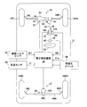
- FIG. 1 is a schematic configuration diagram showing a first embodiment of a vehicle steering control device according to the present invention applied to a vehicle equipped with a front wheel steering angle varying device and a rear wheel steering device. It is a flowchart which shows the main routine of the steering control in 1st embodiment.
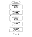
- FIG. 3 is a flowchart showing a front wheel target rudder angle ⁇ ft calculation routine executed in step 200 of FIG. 2.
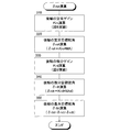
- FIG. 4 is a flowchart showing a rear wheel basic target steering angle ⁇ rbt calculation routine executed in step 300 of FIG. 2.
- FIG. FIG. 4 is a flowchart showing a rear wheel target correction steering angle ⁇ rbt calculation routine executed in step 400 of FIG. 2.
- FIG. 3 is a flowchart showing a front wheel target rudder angle ⁇ ft calculation routine executed in step 200 of FIG. 2.
- FIG. 4 is a flowchart showing a rear wheel basic target steering angle ⁇ rbt calculation routine executed in step 300 of FIG. 2.
- FIG. 4
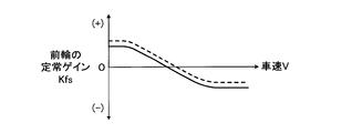
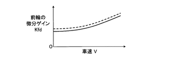
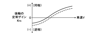
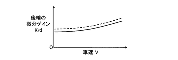
- FIG. 7 is a map for calculating a front wheel steady gain Kfs based on a vehicle speed V; 6 is a map for calculating a front wheel differential gain Kfd based on a vehicle speed V; 6 is a map for calculating a rear wheel steady gain Krs based on a vehicle speed V; 4 is a map for calculating a rear wheel differential gain Krd based on a vehicle speed V; FIG. 6 is a map for calculating a rear wheel basic target correction steering angle ⁇ brt based on a steering angle MA.
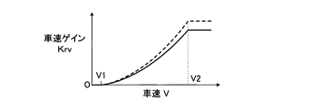
- FIG. 6 is a map for calculating a vehicle speed gain Krv based on the vehicle speed V.
- FIG. 5 is a schematic configuration diagram showing a second embodiment of a vehicle steering control device according to the present invention applied to a vehicle equipped with a steering angle varying device for a front wheel and a rear wheel steering device. It is a flowchart which shows the principal part of the main routine of the steering control in 2nd embodiment.
- FIG. 15 is a flowchart showing a front wheel target rudder angle ⁇ ft calculation routine executed in step 500 of FIG. 14.
- FIG. FIG. 15 is a flowchart showing a rear wheel basic target rudder angle ⁇ rbt calculation routine executed in step 600 of FIG. 14.
- FIG. 15 is a flowchart showing a rear wheel target correction steering angle ⁇ rbt calculation routine executed in step 700 of FIG. 14.
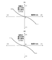
- FIG. The figure which shows an example (B) of the change of the map in the case where the basic target correction steering angle (DELTA) deltabrt of a rear wheel is calculated without setting what is called a dead zone about the steering angle MA, and the situation where the neutral shift
- DELTA basic target correction steering angle
- FIG. 5 is a map for calculating a basic target correction steering angle ⁇ brt based on a steering angle MA and a vehicle speed V in a situation where the vehicle travel mode is a normal mode.
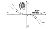
- FIG. 7 is a map for calculating a basic target correction steering angle ⁇ brt based on the steering angle MA and the vehicle speed V in a situation where the vehicle travel mode is the sport mode. It is a map for calculating a basic target correction steering angle ⁇ brt based on the lateral acceleration Gy of the vehicle.
- FIG. 1 is a schematic configuration diagram showing a first embodiment of a vehicle steering control device according to the present invention applied to a vehicle equipped with a front wheel steering angle varying device and a rear wheel steering device.
- reference numeral 10 denotes a steering control device mounted on a vehicle 12.
- the steering control device 10 includes a front wheel steering angle varying device 14, a rear wheel steering device 42, and an electronic control device 16 that controls them.
- 18FL and 18FR respectively indicate left and right front wheels of the vehicle 12
- 18RL and 18RR respectively indicate left and right rear wheels.
- the left and right front wheels 18FL and 18FR which are steered wheels, are connected to a rack bar 24 and tie rods 26L and 26R by a rack and pinion type electric power steering device 22 driven in response to an operation of the steering wheel 20 by a driver. It is steered through.
- the steering wheel 20 that is a steering input device is drivingly connected to the pinion shaft 34 of the power steering device 22 via the upper steering shaft 28, the steering angle varying device 14, the lower steering shaft 30, and the universal joint 32.
- the steering angle varying device 14 is connected to the lower end of the upper steering shaft 28 on the housing 14A side, and is connected to the upper end of the lower steering shaft 30 via a speed reduction mechanism not shown in the drawing on the rotor 14B side.
- the auxiliary steering drive motor 36 is included.
- the rudder angle varying device 14 rotationally drives the lower steering shaft 30 relative to the upper steering shaft 28 to drive auxiliary steering of the left and right front wheels 18FL and 18FR relative to the steering wheel 20. Therefore, the steering angle varying device 14 functions as a steering gear ratio varying device (VGRS) that changes the steering gear ratio (reciprocal of the steering transmission ratio). Further, the rudder angle varying device 14 changes the relationship between the rotational position of the steering wheel 20 and the rudder angle of the front wheels by changing the rudder angle of the left and right front wheels regardless of whether the driver performs a steering operation. It also functions as a steering angle variable device. As will be described in detail later, the steering angle varying device 14 is controlled by a steering angle control unit of the electronic control device 16.
- VGRS steering gear ratio varying device
- the rear wheel steering device 42 includes an electric power steering device 44.
- the power steering device 44 is independent of the steering of the left and right front wheels 18FL and 18FR, and the left and right rear wheels 18RL and 18RR via tie rods 46L and 46R. Steering. Therefore, the rear wheel steering device 42 functions as a rear wheel steering angle varying device that changes the steering angle of the left and right rear wheels without depending on the steering operation of the driver, and the steering angle control of the electronic control device 16 as described later. Controlled by the unit.
- the illustrated rear wheel steering device 42 is an electric auxiliary steering device having a known configuration, and includes an electric motor 48A and, for example, a screw-type motion conversion mechanism 48C that converts the rotation of the electric motor 48A into a reciprocating motion of the relay rod 48B. .
- the relay rod 48B cooperates with the tie rods 46L and 46R and a knuckle arm (not shown) to constitute a steering mechanism that drives the left and right rear wheels 18RL and 18RR by reciprocating movement of the relay rod 48B. ing.
- the motion conversion mechanism 48C converts the rotation of the motor 48A into the reciprocating motion of the relay rod 48B, but the left and right rear wheels 18RL and 18RR are received from the road surface and transmitted to the relay rod 48B. The force is not transmitted to the motor 48A. Therefore, the rear wheel steering device 42 is configured such that the electric motor 48A is not rotationally driven by the force transmitted from the road surface to the relay rod 48B.
- the electric power steering device 22 is a rack coaxial electric power steering device, and converts the electric motor 50 and the rotational torque of the electric motor 50 into a force in the reciprocating direction of the rack bar 24. And a ball screw type conversion mechanism 52.
- the power steering device 22 is controlled by an electric power steering device (EPS) control unit of the electronic control device 16.
- EPS electric power steering device
- the electric power steering device 22 reduces the steering burden on the driver and assists the operation of the steering angle varying device 14 by generating an auxiliary steering force that drives the rack bar 24 relative to the housing 54. It functions as a steering assist force generator.
- the rudder angle varying device 14 and the rear wheel steering device 42 have arbitrary configurations as long as they can change the rudder angles of the front wheels and the rear wheels, respectively, regardless of the driver's steering operation as necessary. It's okay.
- the steering assist force generator may be of any configuration as long as it can generate the assist steering force.
- the steering input device is the steering wheel 20, the steering input device may be a joystick type steering lever.
- the upper steering shaft 28 is provided with a steering angle sensor 60 that detects the rotation angle of the upper steering shaft as the steering angle MA.
- the pinion shaft 34 is provided with a steering torque sensor 62 that detects the steering torque MT.
- the steering angle varying device 14 is provided with a rotation angle sensor 64 that detects the relative rotation angle ⁇ re, that is, the relative rotation angle of the lower steering shaft 30 with respect to the upper steering shaft 28.
- the signal indicating the steering angle MA, the signal indicating the steering torque MT, and the signal indicating the relative rotation angle ⁇ re are a signal indicating the vehicle speed V detected by the vehicle speed sensor 66 and a steering angle control unit and an EPS control unit of the electronic control unit 16. Is input.
- the rotation angle of the lower steering shaft 30 may be detected, and the relative rotation angle ⁇ re may be obtained as a difference between the steering angle ⁇ and the rotation angle of the lower steering shaft 30.
- Each control unit of the electronic control device 16 may include a microcomputer having a CPU, a ROM, a RAM, and an input / output port device, which are connected to each other via a bidirectional common bus. Further, the steering angle sensor 60, the steering torque sensor 62, and the rotation angle sensor 64 detect the steering angle MA, the steering torque MT, and the relative rotation angle ⁇ re, respectively, when the steering or turning in the right turn direction of the vehicle is positive. To do.
- the electronic control device 16 controls the steering angle of the front and rear wheels by controlling the steering angle varying device 14 and the rear wheel steering device 42 according to the flowcharts shown in FIGS. Take control.
- the electronic control unit 16 controls the rudder angle of the front and rear wheels so that the driver's steering request is satisfied, and also improves the turning ability of the vehicle when turning, as necessary. Correct the rudder angle.
- the electronic control unit 16 calculates a front wheel target rudder angle ⁇ ft and a rear wheel basic target rudder angle ⁇ rbt based on the steering angle MA and the vehicle speed V, and further improves the turnability of the vehicle.
- a target correction rudder angle ⁇ rbt is calculated.
- the electronic control unit 16 controls the steering angle of the front wheels based on the target steering angle ⁇ ft, and controls the rear wheels based on the target steering angle ⁇ rt that is the sum of the basic target steering angle ⁇ rbt and the target correction steering angle ⁇ rbt. Control the corners.
- the electronic control device 16 controls the electric power steering device 22 based on the steering torque MT and the like to reduce the steering burden on the driver, and the steering angle varying device 14 determines the steering angle of the left and right front wheels as a target steering angle. Help control to ⁇ ft.
- FIG. 2 ⁇ Main routine of steering control>
- step 50 a signal indicating the steering angle MA detected by the steering angle sensor 64 is read.
- step 200 the target steering angle ⁇ ft of the front wheels is calculated based on the steering angle MA and the vehicle speed V in accordance with the flowchart shown in FIG.
- step 300 the basic target rudder angle ⁇ rbt of the rear wheels is calculated based on the steering angle MA and the vehicle speed V in accordance with the flowchart shown in FIG.
- step 400 the target corrected steering angle ⁇ rbt of the rear wheels for improving the turning ability of the vehicle is calculated based on the steering angle MA and the vehicle speed V according to the flowchart shown in FIG.
- step 800 the rudder angle varying device 14 is controlled so that the rudder angle of the front wheels becomes the target rudder angle ⁇ ft.
- step 900 the sum of the basic target rudder angle ⁇ rbt and the target correction rudder angle ⁇ rbt is calculated as the rear wheel target rudder angle ⁇ rt, and the rear wheel steering is performed so that the rear wheel rudder angle becomes the target rudder angle ⁇ rt.
- the device 42 is controlled.
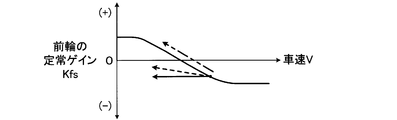
- the front wheel steady gain Kfs is calculated based on the vehicle speed V from the map shown by the solid line in FIG.
- the steady gain Kfs is calculated so as to be a positive value (acceleration gain) in the low vehicle speed range and a negative value (deceleration gain) in the medium and high vehicle speed range.
- the steady gain Kfs is calculated such that it increases as the vehicle speed V decreases in the low vehicle speed region, and increases in absolute value as the vehicle speed V increases in the medium and high vehicle speed regions.
- step 120 the steady target steering angle ⁇ fst of the front wheels is calculated as a product Kfs * MA of the steady gain Kfs calculated in step 110 and the steering angle MA.
- step 130 based on the vehicle speed V, the front wheel differential gain Kfd is calculated from the map shown by the solid line in FIG.
- the differential gain Kfd is calculated so as to increase as the vehicle speed V increases, and to increase the increase rate of the differential gain associated with the increase in vehicle speed as the vehicle speed V increases.
- step 140 for example, the steering angular velocity MAd is calculated as a time differential value of the steering angle MA, and the differential target steering angle ⁇ fdt of the front wheels is calculated as the product of the differential gain Kfd calculated in step 130 and the steering angular velocity MAd. Is done.
- step 150 the target steering angle ⁇ ft of the front wheels is calculated as the sum ⁇ fst + ⁇ fdt of the steady target steering angle ⁇ fst calculated in step 120 and the differential target steering angle ⁇ fdt calculated in step 140.
- the steady gain Krs for the rear wheels is calculated from the map shown by the solid line in FIG.
- the steady gain Krs is a negative value in the low vehicle speed range, that is, a gain that is opposite in phase to the front wheels, and a positive value in the middle and high vehicle speed ranges, that is, a gain that is in phase with respect to the front wheels. It is calculated as follows.
- the steady gain Krs is calculated so that the absolute value increases as the vehicle speed V decreases in the low vehicle speed region, and increases as the vehicle speed V increases in the medium and high vehicle speed regions.
- the steady gain Krs may be 0 in the middle vehicle speed range.
- step 320 the steady target steering angle ⁇ rst of the rear wheels is calculated as a product Krs * MA of the steady gain Krs calculated in step 310 and the steering angle MA.
- step 330 the differential gain Krd of the rear wheels is calculated based on the vehicle speed V from the map shown by the solid line in FIG.
- the differential gain Krd is calculated so as to increase as the vehicle speed V increases, and so that the increase rate of the differential gain associated with the increase in vehicle speed increases as the vehicle speed V increases.
- step 340 for example, the steering angular velocity MAd is calculated as a time differential value of the steering angle MA, and the differential target steering angle ⁇ rdt of the rear wheel is the product of the differential gain Krd calculated in step 330 and the steering angular velocity MAd. Calculated.
- step 350 the basic target rudder angle ⁇ rbt of the rear wheel is calculated as a sum ⁇ rst + ⁇ rdt of the steady target rudder angle ⁇ rst calculated in step 320 and the differential target rudder angle ⁇ rdt calculated in step 340.
- the steady target rudder angle ⁇ rst of the rear wheels may be calculated in an arbitrary manner as long as it is calculated so as to be in-phase with respect to the front wheels at least in the high vehicle speed range. In this case, it is preferable that the steady target rudder angle ⁇ rst of the rear wheels is calculated so as to be in a phase opposite to that of the front wheels in the low vehicle speed range.
- step 410 of the rear wheel target correction steering angle ⁇ rbt calculation routine the rear wheel basic target correction steering angle ⁇ brt is calculated from the map indicated by the solid line in FIG. 10 based on the steering angle MA.
- the basic target correction rudder angle ⁇ brt increases toward the opposite phase with respect to the front wheels as the steering angle MA increases, and the steering angle MA increases as the steering angle MA increases. Is calculated so that the increase rate of the basic target correction rudder angle ⁇ brt is increased.
- the basic target corrected steering angle ⁇ brt is calculated to be 0 in the region where the magnitude of the steering angle MA is not more than the lower limit reference value MA1 (positive constant), and the magnitude of the steering angle MA is the upper limit reference value MA2 (MA1). In a region equal to or greater than (a positive constant greater than), a constant value is calculated.
- a vehicle speed gain Krv for rear wheel correction steering is calculated based on the vehicle speed V from the map indicated by the solid line in FIG.
- the vehicle speed gain Krv is calculated so as to increase as the vehicle speed V increases, and to increase the increase rate of the vehicle speed gain associated with the increase in vehicle speed as the vehicle speed V increases.
- the vehicle speed gain Krv is calculated as 0 in a region where the vehicle speed V is lower than the lower limit reference value V1 (positive constant), and in a region where the vehicle speed V is higher than the upper limit reference value V2 (a positive constant greater than V1). Is calculated as a constant value.
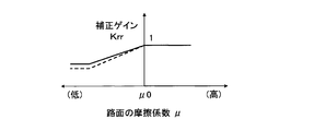
- a correction gain Krr (a positive value of 1 or less) based on the road friction coefficient ⁇ is calculated from the map indicated by the solid line in FIG. 12 based on the road friction coefficient ⁇ .
- the correction gain Krr is calculated as 1 in a region where the friction coefficient ⁇ of the road surface is equal to or larger than the standard value ⁇ 0 (positive constant), and in the region where the friction coefficient ⁇ of the road surface is less than the standard value ⁇ 0, Calculation is performed so that the lower the friction coefficient, the smaller.
- the road surface friction coefficient ⁇ is generally employed in anti-skid control, traction control, vehicle motion control, and the like. It may be a value detected or estimated by any method.
- the rear wheel target correction steering angle ⁇ bt is the product of the vehicle speed gain Krv calculated in step 420, the correction gain Krr calculated in step 430, and the basic target correction steering angle ⁇ brt calculated in step 410. Is calculated.
- step 300 the basic target rudder angle ⁇ rbt of the rear wheel for ensuring a preferable turning response in accordance with the vehicle speed V is calculated, and in step 400, the vehicle has good turning ability. Therefore, the rear wheel target correction steering angle ⁇ rbt is calculated. Then, in step 500, the rear wheel target rudder angle ⁇ rt is calculated as the sum of the basic target rudder angle ⁇ rbt and the vehicle target corrected rudder angle ⁇ rbt.
- the steady target rudder angle ⁇ rst which constitutes the basic target rudder angle ⁇ rbt together with the differential target rudder angle ⁇ rdt, is calculated so that, in the middle and high vehicle speed ranges, the in-phase magnitude of the front wheels increases as the vehicle speed V increases.
- the target correction rudder angle ⁇ rbt is calculated as a control amount for correcting the rudder angle of the rear wheel in the opposite phase to the front wheel, and the magnitude of the control amount is higher as the turning degree of the vehicle is higher, that is, the steering angle.
- the target correction rudder angle ⁇ rbt is large, and the control amount for correcting the rudder angle of the rear wheel in the opposite phase to the front wheel is large. . Therefore, the vehicle slip angle can be increased as compared with the case where the steering angle of the rear wheel is not corrected in the opposite phase direction. It is possible to effectively reduce the fear that the turning performance of the vehicle is bad.
- the target correction rudder angle ⁇ rbt is small, and the control amount for correcting the rudder angle of the rear wheel in the opposite phase to the front wheel is small. Good running stability of the vehicle can be ensured. Further, in this turning traveling situation, since the magnitude of the steering angle MA is generally not a large value, even if the target correction steering angle ⁇ rbt is small, the vehicle occupant does not feel that the turning ability of the vehicle is poor. Absent.
- the ratio of the magnitude of the target corrected steering angle ⁇ rbt of the rear wheels to the magnitude of the steering angle MA, that is, the slope of the map line is The larger the steering angle MA is, the larger it is.
- the magnitude of the corrected rudder angle ⁇ rbt can be increased. Therefore, compared with the case where the ratio is constant, the slip angle of the vehicle in a situation where the steering angle is large can be increased, so there is a possibility that the vehicle occupant may feel a decrease in the turning ability of the vehicle. It can reduce more effectively.
- the vehicle speed gain Krv for the correction steering of the rear wheels increases as the vehicle speed V increases, and the vehicle speed increases as the vehicle speed V increases. Calculation is performed so that the accompanying increase rate increases. Accordingly, the higher the vehicle speed V, the larger the target correction rudder angle ⁇ rbt, and the higher the vehicle speed V, the larger the rate of increase in the target correction rudder angle ⁇ rbt associated with the increase in the vehicle speed.
- the magnitude of the target correction rudder angle ⁇ rbt in a situation where the vehicle speed is high can be increased without excessively increasing the magnitude of the target correction rudder angle ⁇ rbt in a situation where the vehicle speed is low. Therefore, without excessively increasing the slip angle of the vehicle when the vehicle speed is low, the vehicle slip angle when the vehicle speed is high is increased, and the possibility that the vehicle occupant may feel a decrease in the turning performance of the vehicle effectively. Can be reduced.
- FIG. 18A shows a case where the basic target corrected steering angle ⁇ brt of the rear wheels is calculated without setting a so-called dead zone for the steering angle MA
- FIG. 18B shows a neutral deviation. Shows an example of map changes in different situations.
- the basic target corrected steering angle ⁇ brt has a negative value, so the rear wheels are steered in the left turn direction of the vehicle. As a result, the straight traveling performance of the vehicle decreases. Further, when the steering angle MA is steered so as to change in the right turn direction, the rate of increase in the magnitude of the basic target correction steering angle ⁇ brt is increased, so that the rear wheels are corrected in the direction opposite to the front wheels. The rate of increase of the steering amount also increases.
- the rear wheel basic target correction steering angle ⁇ brt is calculated to be 0, Rear wheel steering is not corrected. Therefore, as shown in FIG. 19, even when a neutral deviation occurs, when steering is performed from a position where the steering angle MA is 0, the rear wheels are steered in the same phase as the front wheels, and the steering amount in the same phase is It is possible to reduce the possibility of occurrence of a decreasing situation. Therefore, even if a neutral deviation occurs, the degree to which the turning characteristic of the vehicle varies depending on the steering direction can be reduced, and the driver may feel uncomfortable due to the fact that the turning characteristic of the vehicle varies greatly depending on the steering direction. Can be reduced.
- the vehicle when the friction coefficient ⁇ of the road surface is low, the vehicle is likely to be in an understeer state or an oversteer state.
- the magnitude of the basic target correction steering angle ⁇ brt increases and the rear wheel is corrected and steered with a large correction steering amount, the steering angle of the rear wheel becomes the front wheel.
- the oversteer state of the vehicle is deteriorated.
- the correction gain Krr is calculated so as to decrease as the road surface friction coefficient decreases in a region where the road surface friction coefficient ⁇ is less than the standard value ⁇ 0. Is done. Therefore, when the road surface friction coefficient is low, the basic target correction steering angle ⁇ brt can be made smaller than that when the road surface friction coefficient is high, thereby reducing the correction steering amount. Therefore, when the friction coefficient of the road surface is low, it is possible to reduce the possibility that the vehicle is oversteered due to the correction steering or the oversteer state of the vehicle is deteriorated. Note that when the friction coefficient of the road surface is high, the magnitude of the corrected steering amount is not unnecessarily reduced, so that it is possible to effectively reduce the possibility that the vehicle occupant will feel a decrease in the turning ability of the vehicle. it can.
- the basic target corrected steering angle ⁇ brt of the rear wheels is a constant value in a region where the magnitude of the steering angle MA is not less than the upper limit reference value MA2. Even if the calculated steering angle MA is larger than the upper limit reference value MA2, it does not increase. Therefore, even if the steering angle MA becomes larger than the upper limit reference value MA2, it is possible to prevent the corrected steering amount from becoming excessively large. As a result, the cornering force of the rear wheels is lowered and the vehicle is oversteered. The risk of becoming a state can be effectively reduced.
- the steady-state gains Kfs and Krs are set, for example, as shown by solid arrows in FIGS.
- the value at the start of braking may be maintained until the end.
- the steady gain Kfs increases gently from the value at the start of braking until the braking ends
- the steady gain Krs is the value at the start of braking. It may be controlled to decrease more gently. According to these controls, as shown by the phantom arrows in FIGS. 20 and 21, the change in the steering angle of the front and rear wheels when the vehicle speed decreases compared to the case where the above control is not performed. It is possible to reduce the possibility that the vehicle is oversteered by calming the vehicle.
- FIG. 13 is a schematic configuration diagram showing a second embodiment of a vehicle steering control device according to the present invention applied to a vehicle equipped with a front wheel steering angle varying device and a rear wheel steering device.
- the same members as those shown in FIG. 1 are denoted by the same reference numerals as those shown in FIG.
- the vehicle 12 includes a changeover switch 68, and the vehicle travel mode is switched between the normal mode and the sport mode when the changeover switch 68 is operated by a vehicle occupant. ing.
- the sport mode the turning response of the vehicle is controlled to be higher than in the normal mode where the turning response is normal.
- the steering control is executed according to the flowcharts shown in FIGS.
- FIG. 14 the same step numbers as those shown in FIG. 2 are assigned to the same steps as those shown in FIG. ⁇ Main routine of steering control> (FIG. 14)
- control according to the flowchart shown in FIG. 14 is started when an ignition switch (not shown) is switched from OFF to ON, and is repeatedly executed every predetermined time.
- step 110 it is determined whether or not the traveling mode is the normal mode. If a negative determination is made, the control proceeds to step 150. If an affirmative determination is made, the control proceeds to step 120. .
- step 120 it is determined whether or not the driving mode has been switched from the sport mode to the normal mode. When a negative determination is made, the control proceeds to step 200, and when an affirmative determination is made, the control proceeds to step 130. Proceed to
- step 130 it is determined whether or not the migration process executed in step 140 described later has been completed. When an affirmative determination is made, the information indicating that the travel mode has been switched is cleared, and then control proceeds to step 200. When a negative determination is made, control proceeds to step 140.
- step 140 the map shown in FIG. 6 to FIG. 11 is gradually changed from a broken line to a solid line for each control cycle, whereby a transition process from the sport mode to the normal mode in which each control amount is gradually changed is performed.
- the amount of change in the basic target correction steering angle ⁇ brt that accompanies the shift of the travel mode increases as the steering angle MA increases. Therefore, the change of the map from the broken line to the solid line is performed over a longer time as the magnitude of the steering angle MA is larger.
- Steps 200 to 400 are executed in the same manner as in the first embodiment described above, and when step 400 is completed, control proceeds to step 800.
- step 150 it is determined whether or not the driving mode has been switched from the normal mode to the sport mode. When a negative determination is made, the control proceeds to step 500, and when an affirmative determination is made, the control is performed. Proceed to step 160.
- the gains Kfs, Kfd, Krs, and Krd, the rear wheel basic target correction steering angle ⁇ brt, the vehicle speed gain Krv, and the correction gain Krr change. It is calculated from the map on the way.
- step 160 it is determined whether or not the migration process executed in step 170 described later has been completed. When an affirmative determination is made, the information indicating that the travel mode has been switched is cleared, and then the control proceeds to step 500. When a negative determination is made, the control proceeds to step 170.
- step 170 the map shown in FIGS. 6 to 11 is gradually changed from a solid line to a broken line for each control cycle, so that a transition process from the normal mode to the sport mode in which each control amount is gradually changed is performed.
- the change of the map from the solid line to the broken line is performed over a longer time as the steering angle MA is larger, as in step 140.
- Steps 500 to 700 are executed according to the flowcharts shown in FIGS. 15 to 17 corresponding to the flowcharts shown in FIGS. 3 to 5, respectively.
- step 700 is completed, the control proceeds to step 800.
- step 510 the steady gain Kfs of the front wheels is calculated from the map indicated by the broken line in FIG. 6 based on the vehicle speed V.
- step 530 the map indicated by the broken line in FIG. Further, the front wheel differential gain Kfd is calculated.
- the steady gain Kfs and the differential gain Kfd are calculated from the map that is in the process of changing.
- steps 520, 540, and 550 are performed in the same manner as steps 220, 240, and 250, respectively.
- step 610 the steady gain Krs of the rear wheels is calculated from the map indicated by the broken line in FIG. 8 on the basis of the vehicle speed V, and in step 630, indicated by the broken line in FIG.
- the differential gain Krd of the rear wheel is calculated from the map.
- step 170 when the map is being changed by the transition processing in step 170, the steady gain Krs and the differential gain Krd are calculated from the map that is in the process of changing.
- steps 620, 640, and 650 are performed in the same manner as steps 320, 340, and 350, respectively.
- step 710 the basic target corrected steering angle ⁇ brt of the rear wheels is calculated from the map shown by the broken line in FIG. 10 based on the steering angle MA.
- step 720 the broken line in FIG.
- the vehicle speed gain Krv for rear wheel correction steering is calculated from the map shown in FIG.
- the lower limit value MA1 ′ and the upper limit value M2 ′ of the steering angle MA for calculating the rear wheel basic target correction steering angle ⁇ brt from the map shown by the broken line are shown by the solid line. It is smaller than the lower limit value MA1 and the upper limit value M2 of the map. Further, the magnitude of the basic target correction rudder angle ⁇ brt of the map indicated by the broken line is larger than the magnitude of the basic target correction rudder angle ⁇ brt of the map indicated by the solid line, and the difference is the magnitude of the steering angle MA. The larger the is, the larger.
- a correction gain Krr based on the road friction coefficient ⁇ is calculated from the map shown by the broken line in FIG. 12 based on the road friction coefficient ⁇ .
- the correction gain Krr is calculated as 1 in a region where the friction coefficient ⁇ of the road surface is equal to or larger than the standard value ⁇ 0, and in a region where the friction coefficient ⁇ of the road surface is smaller than the standard value ⁇ 0, the correction gain Krr is larger than the value in the case of the solid line. Calculation is performed so that the smaller the friction coefficient of the road surface is, the smaller the value is.
- step 170 When the map is being changed by the transition process in step 170, the basic target correction steering angle ⁇ brt, the vehicle speed gain Krv, and the correction gain Krr are calculated from the map that is in the process of changing. Further, the other steps, that is, step 740 are executed in the same manner as step 440.
- step 110 when the traveling mode of the vehicle is set to the normal mode by the operation of the changeover switch 68, an affirmative determination is made in step 110, and steps 200 to 400 are performed in the normal mode. Steering control is executed.
- step 110 when the traveling mode of the vehicle is set to the sport mode, a negative determination is made in step 110, and steering control in the sport mode is executed in steps 500 to 700.
- the steering angle of the rear wheel can be corrected in the opposite phase to the front wheel in a medium-to-high-speed turning state where the turning degree of the vehicle is high. . Therefore, the slip angle of the vehicle can be increased as compared with the case where the rudder angle of the rear wheels is not corrected in the opposite phase direction, thereby effectively preventing the vehicle occupant from feeling that the turning performance of the vehicle is poor. Can be reduced.
- the corrective steering is performed depending on the turning response of the vehicle.
- the turning lateral acceleration of the vehicle when starting is different. For this reason, it is inevitable that the turning lateral acceleration of the vehicle when the correction steering is started differs depending on whether the driving mode is a normal mode with normal turning responsiveness or a sports mode with high turning responsiveness.
- the basic target correction rudder angle ⁇ brt of the rear wheels is calculated from a map indicated by a solid line when the traveling mode is the normal mode, and is a broken line when the traveling mode is the sports mode. Calculated from the map indicated by.
- the lower limit value MA1 ′ of the steering angle MA of the map indicated by the broken line is smaller than the lower limit value MA1 of the map indicated by the solid line.
- the degree to which the turning lateral acceleration of the vehicle when the correction steering is started varies depending on the traveling mode can be reduced. Accordingly, it is possible to reduce the possibility that the lateral acceleration of the vehicle when the correction steering is started varies greatly depending on the travel mode and that the vehicle occupant feels uncomfortable due to this.
- the size of the basic target correction rudder angle ⁇ brt of the map indicated by the broken line is larger than the size of the basic target correction rudder angle ⁇ brt of the map indicated by the solid line, and the difference between them is the steering angle.
- the larger the size of MA the larger. Therefore, in order to prevent a sudden change in the magnitude of the corrected steering amount when the traveling mode is shifted between the two traveling modes, when the steering angle is large, the steering angle is small. It is preferable to cause the transition to occur slowly compared to.
- the change in the map from the broken line in FIG. 10 to the solid line in step 140 and the change in the map from the solid line in FIG. 10 to the broken line in step 170 are longer as the steering angle MA is larger. Done over time. Therefore, even when the steering angle is large, it is possible to moderate the change in the amount of the corrected steering amount when the traveling mode is changed, and thereby, the rapid change in the rear wheel target corrected steering angle ⁇ rt. And the change of the unpreferable behavior of the vehicle resulting from this can be prevented.
- the upper limit value MA2 ′ of the map shown in FIG. 10 is smaller than the upper limit value M2. Therefore, when the travel mode is the sport mode, it is possible to start the prevention of lowering of the cornering force of the rear wheels at an earlier stage than when the travel mode is the normal mode. Therefore, as compared with the case where the upper limit value MA2 'is equal to or greater than the upper limit value MA2, it is possible to effectively reduce the possibility that the vehicle will be oversteered due to the lower cornering force of the rear wheels. Can do.
- the correction gain Krr is smaller in the region where the road surface friction coefficient ⁇ is smaller than the standard value ⁇ 0, and is smaller as the road surface friction coefficient is lower. It is calculated so that Therefore, the lower the friction coefficient of the road surface, the larger the reduction correction amount of the target correction steering angle ⁇ rt of the rear wheel can be increased. This also causes the vehicle to be in an oversteer state due to a decrease in the cornering force of the rear wheel. The fear of becoming can be effectively reduced.
- the lower limit reference values MA1, MA1 'and the upper limit reference values MA2, M2' of FIG. 10 are positive constants, but when the vehicle speed V is high, the vehicle speed is low. It may be variably set according to the vehicle speed so as to be smaller than the case.
- the correction steering can be performed when the vehicle speed is high, even when the steering angle is small, compared to when the vehicle speed is low.
- the upper limit reference value is variably set as described above, when the vehicle speed is high and there is a high possibility that the running stability of the vehicle is lowered due to the reduction of the cornering force of the rear wheels, the magnitude of the steering angle is set. It is possible to prevent the correction steering amount from increasing at a small stage.
- the rear wheel target correction steering angle ⁇ rbt is calculated as the product of the vehicle speed gain Krv, the correction gain Krr, and the basic target correction steering angle ⁇ brt, thereby correcting the basic target correction.
- the steering angle ⁇ brt is calculated from the map shown in FIG.
- the basic target correction rudder angle ⁇ brt may be calculated from the map shown in FIG. 22 based on the steering angle MA and the vehicle speed V when the vehicle travel mode is the normal mode.
- the basic target correction rudder angle ⁇ brt may be calculated from the map shown in FIG. 23 based on the steering angle MA and the vehicle speed V when the travel mode of the vehicle is the sport mode.
- the rear wheel target correction steering angle ⁇ rbt may be calculated as the product of the correction gain Krr and the basic target correction steering angle ⁇ brt.
- the basic target correction rudder angle ⁇ brt may be calculated from a map indicated by a solid line in FIG. 24 based on the lateral acceleration Gy of the vehicle when the vehicle travel mode is the normal mode.
- the basic target correction rudder angle ⁇ brt may be calculated from a map indicated by a broken line in FIG. 24 based on the lateral acceleration Gy of the vehicle when the traveling mode of the vehicle is the sports mode.
- the rear wheel target correction steering angle ⁇ rbt may be calculated as the product of the correction gain Krr and the basic target correction steering angle ⁇ brt.
- the lateral acceleration Gy of the vehicle may be the actual lateral acceleration Gy detected by the lateral acceleration sensor, and the lateral acceleration Gyh estimated based on the steering angle MA and the vehicle speed V, for example. It may be.
- the value detected by the lateral acceleration sensor is subjected to low-pass filtering so that fluctuation due to disturbance is eliminated.
- the vehicle has the rudder angle varying device 14 that functions as a steering gear ratio varying device, but the present invention is applied to a vehicle that does not have the rudder angle varying device. May be. Further, the present invention may be applied to a vehicle whose front wheels are steered by a steer-by-wire steering device.
- the correction gain Krr based on the road surface friction coefficient ⁇ is calculated from the map shown in FIG. 12 based on the road surface friction coefficient ⁇ .
- the rear wheel target correction steering angle ⁇ rbt is calculated as the product of the vehicle speed gain Krv, the correction gain Krr, and the basic target correction steering angle ⁇ brt.
- the correction gain Krr based on the road friction coefficient ⁇ may be omitted.
- the rear wheel target correction steering angle ⁇ rbt is preferably reduced.
Landscapes
- Engineering & Computer Science (AREA)
- Chemical & Material Sciences (AREA)
- Combustion & Propulsion (AREA)
- Transportation (AREA)
- Mechanical Engineering (AREA)
- Physics & Mathematics (AREA)
- Mathematical Physics (AREA)
- Theoretical Computer Science (AREA)
- Steering Control In Accordance With Driving Conditions (AREA)
- Steering-Linkage Mechanisms And Four-Wheel Steering (AREA)
- Electric Propulsion And Braking For Vehicles (AREA)
Abstract
Description
一般に、車両が中高速にて走行する際の車両の良好な操縦安定性を確保するためには、車両のスリップ角は0又は小さい値であることが好ましい。しかし、車両が中高速にて走行する状況であっても、操舵角の大きさが比較的大きくされる場合には、操舵角の大きさに比して旋回内側への車両のスリップ角が小さくなるため、車両の乗員は車両の回頭性が低下し車体が旋回外側へ向いているように感じてしまう。換言すれば、車両の乗員の体感にとっての車両のスリップ角の適値は、車速によって異なるだけでなく、特に車両が中高速にて走行する場合には、操舵角の大きさによっても異なる。
〔課題を解決するための手段及び発明の効果〕
図1は、前輪用の舵角可変装置及び後輪操舵装置が搭載された車両に適用された本発明による車両の操舵制御装置の第一の実施形態を示す概略構成図である。
次に、図2に示されたフローチャートを参照して第一の実施形態における操舵制御のメインルーチンについて説明する。なお、図2に示されたフローチャートによる制御は、図には示されていないイグニッションスイッチがオフからオンへ切り替えられたときに開始され、所定の時間毎に繰返し実行される。
前輪の目標舵角δft演算ルーチンのステップ110においては、車速Vに基づいて図6において実線にて示されたマップより前輪の定常ゲインKfsが演算される。この場合、定常ゲインKfsは、低車速域に於いては正の値(増速ゲイン)であり、中高車速域に於いては負の値(減速ゲイン)であるよう、演算される。また、定常ゲインKfsは、低車速域に於いては車速Vが低いほど大きくなり、中高車速域に於いては車速Vが高いほど絶対値が大きくなるよう、演算される。
後輪の基本目標舵角δrbt演算ルーチンのステップ310においては、車速Vに基づいて図8において実線にて示されたマップより後輪の定常ゲインKrsが演算される。この場合、定常ゲインKrsは、低車速域に於いては負の値、即ち、前輪に対し逆相のゲインであり、中高車速域においては正の値、即ち、前輪に対し同相のゲインであるよう演算される。また、定常ゲインKrsは、低車速域に於いては車速Vが低いほど絶対値が大きくなり、中高車速域に於いては車速Vが高いほど大きくなるよう、演算される。なお、定常ゲインKrsは、中車速域において0であってもよい。
後輪の目標修正舵角Δδrbt演算ルーチンのステップ410においては、操舵角MAに基づいて図10において実線にて示されたマップより後輪の基本目標修正舵角Δδbrtが演算される。この場合、基本目標修正舵角Δδbrtは、操舵角MAの大きさが大きくなるほど前輪に対し逆相側へ大きくなるよう、また、操舵角MAの大きさが大きいほど操舵角MAの大きさの増大に伴う基本目標修正舵角Δδbrtの増大率が大きくなるよう、演算される。また、基本目標修正舵角Δδbrtは、操舵角MAの大きさが下限基準値MA1(正の定数)以下の領域においては、0に演算され、操舵角MAの大きさが上限基準値MA2(MA1よりも大きい正の定数)以上の領域においては、一定の値に演算される。
図13は、前輪用の舵角可変装置及び後輪操舵装置が搭載された車両に適用された本発明による車両の操舵制御装置の第二の実施形態を示す概略構成図である。なお、図13において、図1に示された部材と同一の部材には図1に於いて付された符号と同一の符号が付されている。
<操舵制御のメインルーチン>(図14)
ステップ510においては、車速Vに基づいて図6において破線にて示されたマップより前輪の定常ゲインKfsが演算され、ステップ530においては、車速Vに基づいて図7において破線にて示されたマップより前輪の微分ゲインKfdが演算される。なお、ステップ170の移行処理によりマップが変化されている過程にあるときには、定常ゲインKfs及び微分ゲインKfdは変化の途上にあるマップより演算される。
ステップ610においては、車速Vに基づいて図8において破線にて示されたマップより後輪の定常ゲインKrsが演算され、ステップ630においては、車速Vに基づいて図9において破線にて示されたマップより後輪の微分ゲインKrdが演算される。
ステップ710においては、操舵角MAに基づいて図10において破線にて示されたマップより後輪の基本目標修正舵角Δδbrtが演算され、ステップ720においては、車速Vに基づいて図11において破線にて示されたマップより後輪の修正操舵用の車速ゲインKrvが演算される。
Claims (11)
- 運転者の操舵操作に応じて前輪を操舵する前輪操舵装置と、運転者の操舵操作によらず後輪を操舵可能な後輪操舵装置とを有する車両の操舵制御装置において、前輪に対し逆相方向への後輪の操舵を修正操舵として、後輪が前記後輪操舵装置によって前輪と同相に操舵されている状況にて運転者の操舵操作量を示す操舵角の大きさが大きいときには、操舵角の大きさが小さいときに比して、修正操舵量の大きさが大きくなるよう、前記後輪操舵装置を制御することを特徴とする車両の操舵制御装置。
- 操舵角の大きさが大きいときには、操舵角の大きさが小さいときに比して、操舵角の大きさに対する修正操舵量の大きさの比が大きいことを特徴とする請求項1に記載の車両の操舵制御装置。
- 修正操舵量の大きさは、車速が高いときには、車速が低いときに比して、大きいことを特徴とする請求項1又は2に記載の車両の操舵制御装置。
- 修正操舵量の大きさは、路面の摩擦係数が低いときには、路面の摩擦係数が高いときに比して、小さいことを特徴とする請求項1ないし3の何れか一つに記載の車両の操舵制御装置。
- 操舵角の大きさが下限基準値以下であるときには、修正操舵を行わないことを特徴とする請求項1ないし4の何れか一つに記載の車両の操舵制御装置。
- 前記下限基準値は、車速が高いときには、車速が低いときに比して、小さいことを特徴とする請求項5に記載の車両の操舵制御装置。
- 車両は通常旋回応答性の走行モード及び高旋回応答性の走行モードの少なくとも二つの走行モードを有し、前記下限基準値は、走行モードが前記高旋回応答性の走行モードであるときには、走行モードが前記通常旋回応答性の走行モードであるときに比して、小さいことを特徴とする請求項5又は6に記載の車両の操舵制御装置。
- 操舵角の大きさが上限基準値以上であるときには、操舵角の大きさが増大しても修正操舵量の大きさを増大させないことを特徴とする請求項1ないし7の何れか一つに記載の車両の操舵制御装置。
- 前記上限基準値は、車速が高いときには、車速が低いときに比して、小さいことを特徴とする請求項8に記載の車両の操舵制御装置。
- 車両は通常旋回応答性の走行モード及び高旋回応答性の走行モードの少なくとも二つの走行モードを有し、前記上限基準値は、走行モードが前記高旋回応答性の走行モードであるときには、走行モードが前記通常旋回応答性の走行モードであるときに比して、小さいことを特徴とする請求項8又は9に記載の車両の操舵制御装置。
- 車両は通常旋回応答性の走行モード及び高旋回応答性の走行モードの少なくとも二つの走行モードを有し、操舵角の大きさに対する修正操舵量の大きさの比は、走行モードが前記高旋回応答性の走行モードであるときには、走行モードが前記通常旋回応答性の走行モードであるときに比して、大きく、走行モードを前記二つの走行モードの間に移行させる際の時間は、操舵角の大きさが大きいときには、操舵角の大きさが小さいときに比して、長いことを特徴とする請求項1ないし4の何れか一つに記載の車両の操舵制御装置。
Priority Applications (5)
| Application Number | Priority Date | Filing Date | Title |
|---|---|---|---|
| PCT/JP2013/059018 WO2014155564A1 (ja) | 2013-03-27 | 2013-03-27 | 車両の操舵制御装置 |
| CN201380075036.XA CN105073556B (zh) | 2013-03-27 | 2013-03-27 | 车辆的转向控制装置 |
| US14/780,091 US10597076B2 (en) | 2013-03-27 | 2013-03-27 | Vehicle steering control device |
| JP2015507771A JP6123884B2 (ja) | 2013-03-27 | 2013-03-27 | 車両の操舵制御装置 |
| DE112013006873.7T DE112013006873B4 (de) | 2013-03-27 | 2013-03-27 | Fahrzeuglenksteuervorrichtung |
Applications Claiming Priority (1)
| Application Number | Priority Date | Filing Date | Title |
|---|---|---|---|
| PCT/JP2013/059018 WO2014155564A1 (ja) | 2013-03-27 | 2013-03-27 | 車両の操舵制御装置 |
Publications (1)
| Publication Number | Publication Date |
|---|---|
| WO2014155564A1 true WO2014155564A1 (ja) | 2014-10-02 |
Family
ID=51622641
Family Applications (1)
| Application Number | Title | Priority Date | Filing Date |
|---|---|---|---|
| PCT/JP2013/059018 Ceased WO2014155564A1 (ja) | 2013-03-27 | 2013-03-27 | 車両の操舵制御装置 |
Country Status (5)
| Country | Link |
|---|---|
| US (1) | US10597076B2 (ja) |
| JP (1) | JP6123884B2 (ja) |
| CN (1) | CN105073556B (ja) |
| DE (1) | DE112013006873B4 (ja) |
| WO (1) | WO2014155564A1 (ja) |
Families Citing this family (11)
| Publication number | Priority date | Publication date | Assignee | Title |
|---|---|---|---|---|
| DE102015220361B4 (de) * | 2015-10-20 | 2025-08-07 | Volkswagen Aktiengesellschaft | Lenksystem mit Vorderachslenkung und Hinterachslenkung, Verfahren zur Steuerung eines derartigen Lenksystems sowie Kraftfahrzeug |
| JP6202480B1 (ja) * | 2016-04-22 | 2017-09-27 | マツダ株式会社 | 車両用挙動制御装置 |
| JP2018047827A (ja) * | 2016-09-23 | 2018-03-29 | トヨタ自動車株式会社 | 操舵制御装置 |
| CN108454751A (zh) * | 2017-02-21 | 2018-08-28 | 北京凌云智能科技有限公司 | 两轮车转向控制方法及两轮车 |
| DE102017214380A1 (de) * | 2017-08-18 | 2019-02-21 | Volkswagen Aktiengesellschaft | Lenkwinkelregler |
| DE102017129322A1 (de) * | 2017-12-08 | 2019-06-13 | Trw Automotive Gmbh | Allradlenkungssystem für ein Kraftfahrzeug, Kraftfahrzeug sowie Verfahren zum Betrieb eines Allradlenkungssystems |
| CN108427417B (zh) * | 2018-03-30 | 2020-11-24 | 北京图森智途科技有限公司 | 自动驾驶控制系统及方法、计算机服务器和自动驾驶车辆 |
| JP6463571B1 (ja) * | 2018-07-03 | 2019-02-06 | 三菱電機株式会社 | 車両制御装置 |
| WO2020130479A1 (ko) * | 2018-12-19 | 2020-06-25 | 주식회사 만도 | 조향 제어 장치와 조향 제어 방법, 및 조향 장치 |
| KR102808602B1 (ko) * | 2019-09-11 | 2025-05-20 | 에이치엘만도 주식회사 | 조향 제어 장치 및 그 방법, 그리고 조향 시스템 |
| DE102023210367A1 (de) * | 2023-10-20 | 2025-04-24 | Zf Automotive Germany Gmbh | Steer-by-wire-Lenksystem und Verfahren |
Citations (3)
| Publication number | Priority date | Publication date | Assignee | Title |
|---|---|---|---|---|
| JPH02274666A (ja) * | 1989-04-14 | 1990-11-08 | Honda Motor Co Ltd | 4輪操舵装置 |
| JPH05213224A (ja) * | 1992-02-07 | 1993-08-24 | Mazda Motor Corp | 車両の後輪操舵装置 |
| JP2008018832A (ja) * | 2006-07-12 | 2008-01-31 | Fuji Heavy Ind Ltd | 車両運動制御装置 |
Family Cites Families (18)
| Publication number | Priority date | Publication date | Assignee | Title |
|---|---|---|---|---|
| FR2576271B1 (fr) * | 1985-01-24 | 1989-02-17 | Honda Motor Co Ltd | Dispositif de direction des roues avant et arriere |
| DE3804587A1 (de) * | 1988-02-13 | 1989-08-24 | Daimler Benz Ag | Zusatzlenkung |
| US5492348A (en) * | 1992-09-29 | 1996-02-20 | Shaw; David C. | Vehicle steering system |
| US20010027892A1 (en) * | 2000-02-02 | 2001-10-11 | Nathan Masters | Traction kinking system for applying power to a trailing section of an articulated vehicle |
| JP4231910B2 (ja) * | 2000-04-25 | 2009-03-04 | 日産自動車株式会社 | 車線維持装置 |
| JP2003040132A (ja) * | 2001-07-27 | 2003-02-13 | Mitsubishi Motors Corp | 走行レーン逸脱防止装置 |
| US6564131B2 (en) * | 2001-08-01 | 2003-05-13 | Delphi Technologies, Inc. | Four-wheel steering algorithm with functional and diagnostic states and modes |
| US6804592B2 (en) * | 2001-10-18 | 2004-10-12 | Delphi Technologies, Inc. | Four wheel steering compensation for low coefficient of friction surface |
| JP3747316B2 (ja) * | 2001-11-16 | 2006-02-22 | 学校法人金沢工業大学 | 電気移動車両の操舵・駆動制御方法ならびに電気移動車両の操舵・駆動制御装置および電気移動車両 |
| JP4247986B2 (ja) * | 2003-12-10 | 2009-04-02 | 株式会社小松製作所 | 車両のステアリング制御装置 |
| JP2008155889A (ja) * | 2006-12-26 | 2008-07-10 | Toyota Motor Corp | 車両の走行安定状態判定装置及びこれを用いた走行状態安定制御装置 |
| JP4924378B2 (ja) * | 2007-11-19 | 2012-04-25 | トヨタ自動車株式会社 | 車輌の走行制御装置 |
| EP2216234B1 (en) * | 2007-11-19 | 2016-04-13 | Toyota Jidosha Kabushiki Kaisha | Vehicle steering control device |
| JP5144304B2 (ja) * | 2008-02-22 | 2013-02-13 | 本田技研工業株式会社 | 車両の後輪操舵装置 |
| JPWO2009130866A1 (ja) * | 2008-04-25 | 2011-08-11 | 株式会社小松製作所 | 作業車両のステアリング制御装置及びステアリング制御方法 |
| WO2010100719A1 (ja) * | 2009-03-03 | 2010-09-10 | トヨタ自動車株式会社 | 車両の操舵制御装置 |
| JP2012131471A (ja) * | 2010-11-29 | 2012-07-12 | Honda Motor Co Ltd | 電動ステアリング装置 |
| US9321480B2 (en) * | 2011-06-01 | 2016-04-26 | Toyota Jidosha Kabushiki Kaisha | Vehicle steering control apparatus |
-
2013
- 2013-03-27 DE DE112013006873.7T patent/DE112013006873B4/de not_active Expired - Fee Related
- 2013-03-27 WO PCT/JP2013/059018 patent/WO2014155564A1/ja not_active Ceased
- 2013-03-27 US US14/780,091 patent/US10597076B2/en active Active
- 2013-03-27 JP JP2015507771A patent/JP6123884B2/ja not_active Expired - Fee Related
- 2013-03-27 CN CN201380075036.XA patent/CN105073556B/zh not_active Expired - Fee Related
Patent Citations (3)
| Publication number | Priority date | Publication date | Assignee | Title |
|---|---|---|---|---|
| JPH02274666A (ja) * | 1989-04-14 | 1990-11-08 | Honda Motor Co Ltd | 4輪操舵装置 |
| JPH05213224A (ja) * | 1992-02-07 | 1993-08-24 | Mazda Motor Corp | 車両の後輪操舵装置 |
| JP2008018832A (ja) * | 2006-07-12 | 2008-01-31 | Fuji Heavy Ind Ltd | 車両運動制御装置 |
Also Published As
| Publication number | Publication date |
|---|---|
| CN105073556B (zh) | 2017-08-15 |
| US10597076B2 (en) | 2020-03-24 |
| CN105073556A (zh) | 2015-11-18 |
| JPWO2014155564A1 (ja) | 2017-02-16 |
| DE112013006873B4 (de) | 2020-03-19 |
| DE112013006873T5 (de) | 2015-12-24 |
| JP6123884B2 (ja) | 2017-05-10 |
| US20160046321A1 (en) | 2016-02-18 |
Similar Documents
| Publication | Publication Date | Title |
|---|---|---|
| JP6123884B2 (ja) | 車両の操舵制御装置 | |
| US10144416B2 (en) | Apparatus and method for controlling vehicle | |
| JP4924378B2 (ja) | 車輌の走行制御装置 | |
| EP2119616B1 (en) | Steering device for vehicle | |
| US8346434B2 (en) | Vehicle-body behavior control apparatus | |
| JP5983759B2 (ja) | 車両の走行制御装置 | |
| JP4468509B2 (ja) | 車両用操舵装置 | |
| WO2014068711A1 (ja) | 車両の走行制御装置 | |
| CN101172488B (zh) | 电气式动力转向装置 | |
| JPWO2009069242A1 (ja) | 後輪操舵車両 | |
| WO2014010015A1 (ja) | 車両用操舵制御装置 | |
| JP2006347286A (ja) | 車両用操舵装置 | |
| JP5223785B2 (ja) | 車両用操舵伝達比可変式操舵装置 | |
| JP4636255B2 (ja) | 車輪横力推定装置及び操舵反力制御装置 | |
| JP4034621B2 (ja) | 車輌用操舵応答特性制御装置 | |
| JP6256319B2 (ja) | パワーステアリング制御装置 | |
| JP6311589B2 (ja) | パワーステアリング制御装置 | |
| JP2011201507A (ja) | 後輪操舵制御装置 | |
| JP4775091B2 (ja) | 車両の走行制御装置 | |
| JP4715472B2 (ja) | 車輌の操舵制御装置 | |
| JP4238809B2 (ja) | 操舵制御装置 | |
| JP4254710B2 (ja) | 車輌用操舵制御装置 | |
| JP4830569B2 (ja) | 車両の走行制御装置 | |
| JP3675212B2 (ja) | 車輌の操舵制御装置 | |
| JP4775054B2 (ja) | 車両の走行制御装置 |
Legal Events
| Date | Code | Title | Description |
|---|---|---|---|
| WWE | Wipo information: entry into national phase |
Ref document number: 201380075036.X Country of ref document: CN |
|
| 121 | Ep: the epo has been informed by wipo that ep was designated in this application |
Ref document number: 13880012 Country of ref document: EP Kind code of ref document: A1 |
|
| ENP | Entry into the national phase |
Ref document number: 2015507771 Country of ref document: JP Kind code of ref document: A |
|
| WWE | Wipo information: entry into national phase |
Ref document number: 14780091 Country of ref document: US |
|
| WWE | Wipo information: entry into national phase |
Ref document number: 1120130068737 Country of ref document: DE Ref document number: 112013006873 Country of ref document: DE |
|
| 122 | Ep: pct application non-entry in european phase |
Ref document number: 13880012 Country of ref document: EP Kind code of ref document: A1 |