WO2014148191A1 - Dispositif de commande de combustible pour moteur à gaz - Google Patents
Dispositif de commande de combustible pour moteur à gaz Download PDFInfo
- Publication number
- WO2014148191A1 WO2014148191A1 PCT/JP2014/054049 JP2014054049W WO2014148191A1 WO 2014148191 A1 WO2014148191 A1 WO 2014148191A1 JP 2014054049 W JP2014054049 W JP 2014054049W WO 2014148191 A1 WO2014148191 A1 WO 2014148191A1
- Authority
- WO
- WIPO (PCT)
- Prior art keywords
- knocking
- cylinder
- return
- gas fuel
- gas
- Prior art date
Links
Images


Classifications
-
- F—MECHANICAL ENGINEERING; LIGHTING; HEATING; WEAPONS; BLASTING
- F02—COMBUSTION ENGINES; HOT-GAS OR COMBUSTION-PRODUCT ENGINE PLANTS
- F02D—CONTROLLING COMBUSTION ENGINES
- F02D35/00—Controlling engines, dependent on conditions exterior or interior to engines, not otherwise provided for
- F02D35/02—Controlling engines, dependent on conditions exterior or interior to engines, not otherwise provided for on interior conditions
- F02D35/027—Controlling engines, dependent on conditions exterior or interior to engines, not otherwise provided for on interior conditions using knock sensors
-
- F—MECHANICAL ENGINEERING; LIGHTING; HEATING; WEAPONS; BLASTING
- F02—COMBUSTION ENGINES; HOT-GAS OR COMBUSTION-PRODUCT ENGINE PLANTS
- F02D—CONTROLLING COMBUSTION ENGINES
- F02D19/00—Controlling engines characterised by their use of non-liquid fuels, pluralities of fuels, or non-fuel substances added to the combustible mixtures
- F02D19/02—Controlling engines characterised by their use of non-liquid fuels, pluralities of fuels, or non-fuel substances added to the combustible mixtures peculiar to engines working with gaseous fuels
-
- F—MECHANICAL ENGINEERING; LIGHTING; HEATING; WEAPONS; BLASTING
- F02—COMBUSTION ENGINES; HOT-GAS OR COMBUSTION-PRODUCT ENGINE PLANTS
- F02D—CONTROLLING COMBUSTION ENGINES
- F02D41/00—Electrical control of supply of combustible mixture or its constituents
- F02D41/0025—Controlling engines characterised by use of non-liquid fuels, pluralities of fuels, or non-fuel substances added to the combustible mixtures
- F02D41/0027—Controlling engines characterised by use of non-liquid fuels, pluralities of fuels, or non-fuel substances added to the combustible mixtures the fuel being gaseous
-
- F—MECHANICAL ENGINEERING; LIGHTING; HEATING; WEAPONS; BLASTING
- F02—COMBUSTION ENGINES; HOT-GAS OR COMBUSTION-PRODUCT ENGINE PLANTS
- F02D—CONTROLLING COMBUSTION ENGINES
- F02D41/00—Electrical control of supply of combustible mixture or its constituents
- F02D41/008—Controlling each cylinder individually
-
- F—MECHANICAL ENGINEERING; LIGHTING; HEATING; WEAPONS; BLASTING
- F02—COMBUSTION ENGINES; HOT-GAS OR COMBUSTION-PRODUCT ENGINE PLANTS
- F02D—CONTROLLING COMBUSTION ENGINES
- F02D41/00—Electrical control of supply of combustible mixture or its constituents
- F02D41/22—Safety or indicating devices for abnormal conditions
-
- F—MECHANICAL ENGINEERING; LIGHTING; HEATING; WEAPONS; BLASTING
- F02—COMBUSTION ENGINES; HOT-GAS OR COMBUSTION-PRODUCT ENGINE PLANTS
- F02D—CONTROLLING COMBUSTION ENGINES
- F02D41/00—Electrical control of supply of combustible mixture or its constituents
- F02D41/30—Controlling fuel injection
- F02D41/3005—Details not otherwise provided for
-
- F—MECHANICAL ENGINEERING; LIGHTING; HEATING; WEAPONS; BLASTING
- F02—COMBUSTION ENGINES; HOT-GAS OR COMBUSTION-PRODUCT ENGINE PLANTS
- F02P—IGNITION, OTHER THAN COMPRESSION IGNITION, FOR INTERNAL-COMBUSTION ENGINES; TESTING OF IGNITION TIMING IN COMPRESSION-IGNITION ENGINES
- F02P5/00—Advancing or retarding ignition; Control therefor
- F02P5/04—Advancing or retarding ignition; Control therefor automatically, as a function of the working conditions of the engine or vehicle or of the atmospheric conditions
- F02P5/145—Advancing or retarding ignition; Control therefor automatically, as a function of the working conditions of the engine or vehicle or of the atmospheric conditions using electrical means
- F02P5/15—Digital data processing
- F02P5/152—Digital data processing dependent on pinking
- F02P5/1522—Digital data processing dependent on pinking with particular means concerning an individual cylinder
-
- F—MECHANICAL ENGINEERING; LIGHTING; HEATING; WEAPONS; BLASTING
- F02—COMBUSTION ENGINES; HOT-GAS OR COMBUSTION-PRODUCT ENGINE PLANTS
- F02D—CONTROLLING COMBUSTION ENGINES
- F02D19/00—Controlling engines characterised by their use of non-liquid fuels, pluralities of fuels, or non-fuel substances added to the combustible mixtures
- F02D19/02—Controlling engines characterised by their use of non-liquid fuels, pluralities of fuels, or non-fuel substances added to the combustible mixtures peculiar to engines working with gaseous fuels
- F02D19/021—Control of components of the fuel supply system
-
- F—MECHANICAL ENGINEERING; LIGHTING; HEATING; WEAPONS; BLASTING
- F02—COMBUSTION ENGINES; HOT-GAS OR COMBUSTION-PRODUCT ENGINE PLANTS
- F02D—CONTROLLING COMBUSTION ENGINES
- F02D19/00—Controlling engines characterised by their use of non-liquid fuels, pluralities of fuels, or non-fuel substances added to the combustible mixtures
- F02D19/02—Controlling engines characterised by their use of non-liquid fuels, pluralities of fuels, or non-fuel substances added to the combustible mixtures peculiar to engines working with gaseous fuels
- F02D19/025—Failure diagnosis or prevention; Safety measures; Testing
-
- F—MECHANICAL ENGINEERING; LIGHTING; HEATING; WEAPONS; BLASTING
- F02—COMBUSTION ENGINES; HOT-GAS OR COMBUSTION-PRODUCT ENGINE PLANTS
- F02D—CONTROLLING COMBUSTION ENGINES
- F02D35/00—Controlling engines, dependent on conditions exterior or interior to engines, not otherwise provided for
- F02D35/02—Controlling engines, dependent on conditions exterior or interior to engines, not otherwise provided for on interior conditions
- F02D35/023—Controlling engines, dependent on conditions exterior or interior to engines, not otherwise provided for on interior conditions by determining the cylinder pressure
-
- F—MECHANICAL ENGINEERING; LIGHTING; HEATING; WEAPONS; BLASTING
- F02—COMBUSTION ENGINES; HOT-GAS OR COMBUSTION-PRODUCT ENGINE PLANTS
- F02D—CONTROLLING COMBUSTION ENGINES
- F02D41/00—Electrical control of supply of combustible mixture or its constituents
- F02D41/008—Controlling each cylinder individually
- F02D41/0087—Selective cylinder activation, i.e. partial cylinder operation
-
- F—MECHANICAL ENGINEERING; LIGHTING; HEATING; WEAPONS; BLASTING
- F02—COMBUSTION ENGINES; HOT-GAS OR COMBUSTION-PRODUCT ENGINE PLANTS
- F02D—CONTROLLING COMBUSTION ENGINES
- F02D41/00—Electrical control of supply of combustible mixture or its constituents
- F02D41/02—Circuit arrangements for generating control signals
- F02D41/04—Introducing corrections for particular operating conditions
- F02D41/12—Introducing corrections for particular operating conditions for deceleration
- F02D41/123—Introducing corrections for particular operating conditions for deceleration the fuel injection being cut-off
- F02D41/126—Introducing corrections for particular operating conditions for deceleration the fuel injection being cut-off transitional corrections at the end of the cut-off period
-
- Y—GENERAL TAGGING OF NEW TECHNOLOGICAL DEVELOPMENTS; GENERAL TAGGING OF CROSS-SECTIONAL TECHNOLOGIES SPANNING OVER SEVERAL SECTIONS OF THE IPC; TECHNICAL SUBJECTS COVERED BY FORMER USPC CROSS-REFERENCE ART COLLECTIONS [XRACs] AND DIGESTS
- Y02—TECHNOLOGIES OR APPLICATIONS FOR MITIGATION OR ADAPTATION AGAINST CLIMATE CHANGE
- Y02T—CLIMATE CHANGE MITIGATION TECHNOLOGIES RELATED TO TRANSPORTATION
- Y02T10/00—Road transport of goods or passengers
- Y02T10/10—Internal combustion engine [ICE] based vehicles
- Y02T10/40—Engine management systems
Definitions
- the present invention relates to a combustion control device for a gas engine, and more particularly to a combustion control device for knocking.
- a power generation facility using a gas engine using natural gas or city gas as a main fuel is installed from the viewpoint of a clean energy source.
- the fuel supply valve provided in each cylinder is controlled and the ignition timing is controlled.
- abnormal combustion such as knocking or misfire may occur. It is necessary to detect and avoid abnormal combustion such as knocking and misfire at an early stage.
- Patent Document 1 Japanese Patent No. 4688916
- Patent Document 2 Japanese Patent No. 4247842
- This Patent Document 1 detects an exhaust temperature for each cylinder of a gas engine, detects a cylinder in which knocking or misfire has occurred, reduces the fuel supply amount to the cylinder having the maximum exhaust temperature, and minimizes the exhaust temperature.
- the load leveling control for increasing the fuel supply amount to the cylinder is executed, and the fuel supply is stopped or decreased for a predetermined period for the cylinder in which knocking or misfire has occurred. Further, it is shown that the cylinders that are countermeasures against knocking or misfire are excluded from the cylinders of the load leveling control.
- Patent Document 2 shows a knock control device for a gas engine, and the magnitude of knocking detected by a knocking sensor is generated in each cylinder based on a calculated value of occurrence frequency of knocking that exceeds a predetermined value.
- the average value of the frequency is compared with the frequency of occurrence in the cylinder. If the frequency of occurrence in the cylinder is equal to or higher than the average value of the frequency of occurrence, the gas injection amount is reduced for the cylinder, If the occurrence frequency in the cylinder is equal to or less than a predetermined frequency from the average value of the occurrence frequency, it is indicated that the gas injection amount to the cylinder is increased.
- Patent Document 1 and Patent Document 2 described above as a countermeasure technique when knocking or misfire occurs, the supply of gas fuel is stopped or reduced with respect to the cylinder in which knocking has occurred, It discloses that the ignition timing is retarded, and does not disclose the return control for returning the gas fuel increase amount or the gas fuel injection timing or the ignition timing again after executing the countermeasure control.
- An object of the present invention is to provide a combustion control device for a gas engine that prevents an unstable combustion state such as a misfire from falling during a return by appropriately performing control.
- the present invention has been made to solve such a problem, and in a combustion control device for a gas engine, knocking determination means for determining occurrence of knocking in each cylinder, and occurrence of knocking is determined by the knocking occurrence determination means.
- the knocking occurs after the stop or decrease, and the knocking reducing means for reducing the supply of gas fuel to the other cylinders where knocking does not occur and the supply of gas fuel to other cylinders where knocking does not occur.
- the supply of gas fuel to the knocking cylinder is stopped or reduced, and the supply of gas fuel is also reduced to other cylinders that do not generate knocking. .
- the air-fuel ratio for the knocking cylinder is shifted to the lean side, and the occurrence of knocking is suppressed.
- the gas fuel is reduced in response to an instruction to reduce the load due to a predetermined decrease in the power generation output in order to prevent overload for the other cylinders in which knocking does not occur.
- the knocking determining means determines that knocking has not occurred, the supply of the reduced or stopped gas fuel is restored to the original state. That is, the required gas fuel amount for the required load is restored.
- the return is caused to recover from the stopped or reduced state of the gas fuel by the first return means, and in the other cylinders other than the knock occurrence cylinder, the second return means is used to return from the reduced state of the gas fuel. . Then, the return time in the first return means is made shorter than the return time in the second return means, and the return of the knocking cylinder is prioritized. For this reason, first, the cylinder in which knocking has occurred is restored, and if there is no abnormality again, that is, it is confirmed again that abnormal combustion such as knocking or misfiring will not recur, In contrast, the return can be terminated. Therefore, the return control can be performed reliably and stably.
- the first return means and the second return means perform the return control when knocking does not occur within a predetermined time after the gas fuel is stopped or reduced by the knock reduction means. It may be configured to start.
- the rate of increase of gas fuel in the first return means is set larger than the rate of increase of gas fuel in the second return means.
- the return time of the first return means can be made shorter than the return time of the second return means by making the increase rate of the gas fuel in the first return means larger than the increase rate of the gas fuel in the second return means.
- the first return means may be set to return in a short time, for example, 2 to 3 seconds after starting the return control.
- the amount of gas fuel reduced by the knocking reducing means is set to be larger for the knocking cylinder than for other cylinders where knocking does not occur.
- the amount of reduction of the gas fuel set by the knocking reduction means at that time may be further added to reduce.
- the knocking reduction and the subsequent return control can be stably performed by further reducing the gas fuel supply amount at that time.
- the return control when returning to the optimal operation by increasing again is appropriately performed, It can prevent falling into unstable combustion states, such as misfire.
- the gas fuel is stopped or returned from the reduced state by the first return means, and the gas fuel is returned from the reduced state by the second return means in the cylinders other than the knocking cylinder.
- the return time of the first return means is made shorter than the return time of the second return means so that the return of the cylinder in which knocking has occurred is prioritized and finished, so that the knocking reoccurs.
- FIG. 1 is a system diagram showing the overall configuration of a combustion control apparatus for a gas engine according to a first embodiment of the present invention.
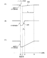
- FIG. 2 is a partial cross-sectional explanatory view showing a structure around a combustion chamber of the gas engine shown in FIG. 1. It is a flowchart of a combustion control apparatus. The return state of the gas fuel by the return means is shown, (A) shows the case of a cylinder other than the knocking cylinder, (B) shows the case of the knocking cylinder, and (C) shows a comparative example. It is explanatory drawing which shows a knocking area
- FIG. 1 shows an overall configuration of a combustion control apparatus for a gas engine according to a first embodiment of the present invention
- FIG. 2 is a partial sectional view around a combustion chamber.
- a gas engine hereinafter simply referred to as an engine
- the crankshaft 2 of the engine 1 is provided with a flywheel 3, and a generator 5 is directly attached to the flywheel 3.
- a gas fuel control device 7 that controls the amount of gas fuel supplied into each cylinder of the engine 1 and an ignition device 9 that ignites the gas fuel supplied into each cylinder are provided.
- a piston 13 slidably fitted in the cylinder 11 a main combustion chamber 17 defined between the upper surface of the piston 13 and the inner surface of the cylinder block 15, the main combustion chamber 17 is provided with an intake port 19 connected to 17, an intake valve 21 for opening and closing the intake port 19, and the like.
- a gas mixer 25 is installed in the supply pipe 23 upstream of the intake port 19, a gas supply pipe 27 is connected, and a gas adjustment valve 29 is provided in the gas supply pipe 27 to adjust the amount of fuel gas.
- the supplied fuel gas and the air supplied through the air supply pipe 23 are premixed by the gas mixer 25. Then, it reaches the intake valve 21 via the intake port 19, and the premixed gas mixture is supplied to the main combustion chamber 17 by opening the intake valve 21.
- the air supply pipe 23, the gas supply pipe 27, the gas regulating valve 29 provided in the gas supply pipe 27, and the gas mixer 25 shown in FIG. 2 are provided for each cylinder.
- an ignition device 9 is provided for each cylinder in the cylinder bed 31 that forms the upper part of the main combustion chamber 17 of each cylinder.
- the ignition device 9 has a structure in which a sub-combustion chamber (sub-chamber) and a spark plug (not shown) are provided.
- the sub-chamber fuel gas supplied to the sub-chamber is ignited by the spark plug, and the sub-chamber is ignited.
- the generated flame is injected into the main combustion chamber 17 to burn the mixed gas in the main combustion chamber 17.
- the ignition device 9 is ignited by an ignition plug at an appropriate timing based on signals from the rotation speed sensor 42, the crank angle sensor 45, and the load sensor 47, and injects a flame into the main combustion chamber 17. Yes.
- an exhaust port 35 is connected to the main combustion chamber 17, and exhaust gas after combustion is discharged from the main combustion chamber 17 by opening the exhaust valve 37.
- An exhaust pipe 39 (not shown) is connected to the downstream side of the exhaust port 35, and an exhaust supercharger (not shown) is attached to the exhaust pipe 39.
- An in-cylinder pressure sensor 41 that detects the in-cylinder pressure in the main combustion chamber 17 is provided for each cylinder, and the flywheel 3 is provided with a rotation speed sensor 42 that detects the engine speed and a crank angle sensor 45.
- the generator 5 is provided with a load sensor 47 for detecting the load of the generator 5, that is, the engine load. Signals from these sensors are input to a combustion control device 43 described later.
- the combustion control device 43 in the engine 1 having the above configuration mainly detects an abnormal combustion state from the change in the in-cylinder pressure in the main combustion chamber 17 of each cylinder based on a signal from the in-cylinder pressure sensor 41, Knocking determination means 49 for determining whether knocking has occurred or not is provided.
- the knocking determination means 49 determines the occurrence of knocking
- the first knocking reduction means 51 that stops or reduces the supply of gas fuel to the knocking occurrence cylinder, and other cylinders other than the knocking occurrence cylinder
- second knocking reducing means 53 for reducing the supply of gas fuel
- knocking reducing means 55 constituted by the second knocking reducing means 55.
- the first knock reduction means 51 stops or reduces the gas fuel for the cylinder in which knocking has occurred. Therefore, the gas fuel is stopped or reduced by controlling the opening of the gas regulating valve 29 provided in the gas supply pipe 27.
- the reduction rate may be set so as to reduce the supply amount at that time by 2 to 3%. Further, since the reduction control becomes complicated, the supply of gas fuel may be uniformly stopped.
- the reduction amount of 2 to 3% is a gas fuel reduction amount necessary for shifting the air-fuel ratio to the lean side in order to suppress knocking.
- the second knocking reduction means 53 reduces the gas fuel to the cylinders other than the knocking cylinder. In this case, since it is a cylinder in which knocking has not occurred, it is not a reduction in gas fuel for shifting the air-fuel ratio to the lean side. In order to prevent overloading by increasing the load sharing of other cylinders (by increasing the load of other cylinders by operating the cover mechanism), the load of the power generation output is reduced.
- the knocking occurrence cylinder The first return means 57 for returning from the stopped or reduced state of the gas fuel to the amount of gas fuel before the occurrence of knocking, and the gas before the torque reduction from the reduced state of the gas fuel in other cylinders other than the knocking occurrence cylinder Second return means 59 for returning to the fuel amount.
- combustion control device 43 further sets the return time in the first return means 57 to be shorter than the return time of the second return means 59, and prioritizes the return of the knocking cylinder to other cylinders that do not generate knocking. Configured to do.
- the cylinder is first restored to the state where knocking has occurred, and if an abnormality does not occur again, that is, after confirming whether or not abnormal combustion such as knocking or misfiring will occur again or while confirming
- the return is also finished for the other cylinders where knocking does not occur. Therefore, the return control can be performed reliably and stably.
- the reduction or return of the gas fuel by the first knocking reduction means 51, the second knocking reduction means 53, the first return means 57, and the second return means 59 of the combustion control device 43 is performed by the gas fuel control device 7. This is done by controlling the opening of the gas regulating valve 29 that constitutes.
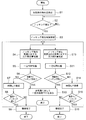
- step S2 in-cylinder pressure of each cylinder is detected in step S1.
- step S2 it is determined whether knocking has occurred, and it is determined whether knocking has occurred. The process is repeated until it occurs. If it has occurred, the cylinder in which knocking has occurred is specified in step S3.
- step S4 the amount of gas fuel for the knocking cylinder is reduced or stopped, and the air-fuel ratio is shifted to lean (t0 in the time chart of FIG. 4B). Thereafter, in step S5, the system waits for a certain period of time with the gas amount reduced or stopped (t0 to t1 in the time chart of FIG. 4B).
- step S6 it is determined whether knocking has occurred during the standby. When it is determined in step S6 that knocking has not occurred, in step S7, it is returned at time ta (t1 to t2 in the time chart of FIG. 4B). In the next step S8, it is determined whether or not knocking has occurred during the return operation. If knocking has not occurred in step S8, the process ends in step S9, assuming that the return is complete. If it is determined in step S8 that knocking has occurred, the process returns to step S4 and is repeated.
- step S10 the amount of gas fuel with respect to other cylinders where no knocking occurs is reduced (t0 in the time chart of FIG. 4A).
- This reduction in the amount of gas fuel is set as a reduction amount of gas fuel commensurate with a load reduction of 2 to 3% KW of the power generation output in order to prevent overload.
- step S11 the system waits for a certain time in the gas amount reduced state (t0 to t1 in the time chart of FIG. 4A).
- step S12 it is determined whether knocking has occurred during the standby. If it is determined in step S12 that knocking has not occurred, it is returned over time tb (t1 to t3 in the time chart of FIG. 4A) in step S14. In the next step S15, it is determined whether knocking has occurred during the return operation. If knocking has not occurred in step S15, the process ends in step S16, assuming that the return is complete. If it is determined in step S15 that knocking has occurred, the process returns to step S10 and is repeated.
- the above steps S10 to S16 have the same processing flow as steps S4 to S9.
- step S13 a constant load reduction is performed on all the cylinders and the gas fuel amount is reduced accordingly.
- FIG. 4 shows a return state by the first return means 57 and the second return means 59.
- (A) is for the cylinders other than the knocking cylinder, and shows the case by the second return means 59
- (B) is for the knocking cylinder and shows the case by the first return means 57
- ( C) shows, as a comparative example, an example in which the supply amount of gas fuel is reduced along a constant load reduction for all cylinders.
- the recovery time tb in the present invention, longer than the recovery time ta
- the gas fuel is gradually increased at the time of return from the state where the temperature in the combustion chamber is lowered, and instability of combustion appears and misfire is likely to occur.
- such an unstable return can be avoided by increasing the amount of gas fuel at once at the return time ta (a time shorter than the return time tb).
- the start of return of the first return means 57 and the second return means 59 is started at the same time as t1, but the second return means shown in FIG.
- the start time of 59 may be started from time t2 when the return by the first return means 57 is completed.
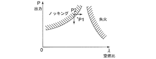
- FIG. 5 shows regions where abnormal combustion (knocking, misfire) of the engine 1 occurs, and shows the respective regions with the air-fuel ratio ⁇ on the horizontal axis and the engine output P on the vertical axis.
- the engine 1 of the present embodiment is operating at a high output and is operated at a substantially constant rotation at the point P1. It is easy to move to the operating point P2 in the knocking region due to fluctuations in power generation load and environmental conditions. When moving to the knocking region, it is necessary to respond from the knocking region to the normal operation region by reducing the output or leaning the air-fuel ratio. In the present embodiment, knocking is avoided by shifting the air-fuel ratio to the lean side by a 2-3% reduction in the amount of gas fuel at the time of operation for the cylinder in which knocking occurs.
- the gas fuel is stopped or reduced for the knocking cylinder, and in the subsequent return control to the optimum operation, the fuel is misfired in order to increase the gas fuel appropriately. It can prevent falling into unstable combustion state.
- the first return means 57 returns the gas fuel from the stopped or reduced state
- the second return means 59 returns the gas fuel from the reduced state in the cylinders other than the knocking cylinder.
- the return time in the first return means 57 is made shorter than the return time of the second return means 59, giving priority to the return of the cylinder in which knocking has occurred, and then the return of other cylinders in which knocking has not occurred. Therefore, the return control can be performed reliably and stably.
- the return control when returning to the optimal operation by increasing the amount again is performed appropriately, and thus misfires, etc. Since it can prevent falling into an unstable combustion state, it is suitable for use in a combustion control device of a gas engine for a generator.
Landscapes
- Engineering & Computer Science (AREA)
- Chemical & Material Sciences (AREA)
- Combustion & Propulsion (AREA)
- Mechanical Engineering (AREA)
- General Engineering & Computer Science (AREA)
- Signal Processing (AREA)
- Combined Controls Of Internal Combustion Engines (AREA)
- Electrical Control Of Air Or Fuel Supplied To Internal-Combustion Engine (AREA)
- Output Control And Ontrol Of Special Type Engine (AREA)
Abstract
Priority Applications (4)
| Application Number | Priority Date | Filing Date | Title |
|---|---|---|---|
| CN201480010866.9A CN105026738B (zh) | 2013-03-19 | 2014-02-20 | 燃气发动机的燃烧控制装置 |
| KR1020157025419A KR101755969B1 (ko) | 2013-03-19 | 2014-02-20 | 가스 엔진의 연소 제어 장치 |
| US14/777,470 US9964053B2 (en) | 2013-03-19 | 2014-02-20 | Combustion control device for gas engine |
| EP14768042.5A EP2957753B1 (fr) | 2013-03-19 | 2014-02-20 | Dispositif de commande de combustible pour moteur à gaz |
Applications Claiming Priority (2)
| Application Number | Priority Date | Filing Date | Title |
|---|---|---|---|
| JP2013056776A JP5951537B2 (ja) | 2013-03-19 | 2013-03-19 | ガスエンジンの燃焼制御装置 |
| JP2013-056776 | 2013-03-19 |
Publications (1)
| Publication Number | Publication Date |
|---|---|
| WO2014148191A1 true WO2014148191A1 (fr) | 2014-09-25 |
Family
ID=51579883
Family Applications (1)
| Application Number | Title | Priority Date | Filing Date |
|---|---|---|---|
| PCT/JP2014/054049 WO2014148191A1 (fr) | 2013-03-19 | 2014-02-20 | Dispositif de commande de combustible pour moteur à gaz |
Country Status (6)
| Country | Link |
|---|---|
| US (1) | US9964053B2 (fr) |
| EP (1) | EP2957753B1 (fr) |
| JP (1) | JP5951537B2 (fr) |
| KR (1) | KR101755969B1 (fr) |
| CN (1) | CN105026738B (fr) |
| WO (1) | WO2014148191A1 (fr) |
Cited By (3)
| Publication number | Priority date | Publication date | Assignee | Title |
|---|---|---|---|---|
| CN105526013A (zh) * | 2014-10-17 | 2016-04-27 | 福特环球技术公司 | 用于发动机爆震控制的判断方法和系统 |
| US9964053B2 (en) | 2013-03-19 | 2018-05-08 | Mitsubishi Heavy Industries, Ltd. | Combustion control device for gas engine |
| EP3244048A4 (fr) * | 2015-01-08 | 2018-08-22 | Mitsubishi Heavy Industries, Ltd. | Procédé de commande du cognement |
Families Citing this family (5)
| Publication number | Priority date | Publication date | Assignee | Title |
|---|---|---|---|---|
| US11952935B2 (en) * | 2011-12-16 | 2024-04-09 | Transportation Ip Holdings, Llc | Systems and method for controlling auto-ignition |
| FR3048262B1 (fr) * | 2016-02-26 | 2018-03-16 | Peugeot Citroen Automobiles Sa | Procede de limitation de charge d'un moteur thermique en cas de detection de combustions anormales |
| CN108533413B (zh) * | 2017-03-01 | 2020-10-09 | 联合汽车电子有限公司 | 一种发动机早燃检测优化方法及系统 |
| JP2021076029A (ja) * | 2019-11-05 | 2021-05-20 | 三菱重工エンジン&ターボチャージャ株式会社 | ガスエンジンの再着火処理装置、再着火方法およびプログラム |
| US11982246B2 (en) * | 2020-11-23 | 2024-05-14 | Transportation Ip Holdings, Llc | Methods and systems for engine |
Citations (7)
| Publication number | Priority date | Publication date | Assignee | Title |
|---|---|---|---|---|
| JPH03185270A (ja) * | 1989-12-15 | 1991-08-13 | Toyota Motor Corp | 内燃機関の点火時期制御装置 |
| JPH0579440A (ja) * | 1991-09-19 | 1993-03-30 | Hitachi Ltd | 点火時期制御装置 |
| JPH0828319A (ja) * | 1994-05-10 | 1996-01-30 | Nippondenso Co Ltd | 内燃機関の燃料噴射制御装置 |
| JP4247842B2 (ja) | 2006-03-16 | 2009-04-02 | 三井造船株式会社 | ガスエンジンのノッキング制御装置 |
| JP2009281251A (ja) * | 2008-05-21 | 2009-12-03 | Toyota Motor Corp | 内燃機関の点火時期制御装置 |
| JP2010084739A (ja) * | 2008-10-02 | 2010-04-15 | Kawasaki Heavy Ind Ltd | ガスエンジンのノッキング制御装置 |
| JP4688916B2 (ja) | 2008-10-01 | 2011-05-25 | 川崎重工業株式会社 | ガスエンジンの制御装置 |
Family Cites Families (21)
| Publication number | Priority date | Publication date | Assignee | Title |
|---|---|---|---|---|
| JPS5820374B2 (ja) * | 1977-10-11 | 1983-04-22 | 日産自動車株式会社 | 内燃機関用電子制御燃料噴射装置 |
| US4243009A (en) * | 1979-09-27 | 1981-01-06 | Brunswick Corporation | Detonation control apparatus for outboard motor |
| DE4002207A1 (de) * | 1990-01-26 | 1991-08-01 | Bosch Gmbh Robert | Katalysatorschutzverfahren |
| DE19709395C2 (de) * | 1997-03-07 | 1998-12-24 | Bosch Gmbh Robert | Verfahren zur Klopfregelung in Mehrzylinder-Brennkraftmaschinen |
| DE19908729A1 (de) * | 1999-03-01 | 2000-09-07 | Bosch Gmbh Robert | Kraftstoffeinspritzverfahren für eine Brennkraftmaschine |
| US6662788B2 (en) * | 2002-04-16 | 2003-12-16 | Lance E. Nist | Remote metering for gaseous fuels and oxidizers |
| US6863034B2 (en) * | 2003-01-17 | 2005-03-08 | Robert D. Kern | Method of controlling a bi-fuel generator set |
| US7533634B2 (en) * | 2004-03-10 | 2009-05-19 | Tgi, Inc. | Process for use with dual-fuel systems |
| FI119395B (fi) * | 2004-03-15 | 2008-10-31 | Waertsilae Finland Oy | Adaptiivinen kuormantasausjärjestelmä |
| JP4424178B2 (ja) * | 2004-11-30 | 2010-03-03 | スズキ株式会社 | 多気筒エンジンの失火検出装置 |
| JP2006183548A (ja) * | 2004-12-27 | 2006-07-13 | Nippon Soken Inc | 内燃機関の制御装置 |
| JP4466864B2 (ja) | 2005-09-21 | 2010-05-26 | 三菱自動車工業株式会社 | 内燃機関の制御装置 |
| JP3968112B2 (ja) * | 2006-01-11 | 2007-08-29 | ヤンマー株式会社 | 副室式ガス機関の制御方法 |
| US7665452B2 (en) * | 2006-03-17 | 2010-02-23 | Ford Global Technologies, Llc | First and second spark plugs for improved combustion control |
| US7302932B2 (en) * | 2006-03-17 | 2007-12-04 | Ford Global Technologies, Llc | Pre-ignition detection and mitigation |
| JP2010112244A (ja) * | 2008-11-05 | 2010-05-20 | Fujitsu Ten Ltd | 制御装置、及び制御方法 |
| JP2011185142A (ja) * | 2010-03-08 | 2011-09-22 | Toyota Motor Corp | 多気筒内燃機関の制御装置 |
| CA2816214A1 (fr) | 2010-10-29 | 2012-05-03 | Afv Alternative Fuel Vehicle | Systeme de moteur a carburation mixte |
| JP5675466B2 (ja) * | 2011-03-31 | 2015-02-25 | 三菱重工業株式会社 | エンジンの燃焼診断信号異常時のパイロット噴射タイミング制御方法および装置 |
| US9038596B2 (en) * | 2011-12-02 | 2015-05-26 | Ford Global Technologies, Llc | Method and system for pre-ignition control |
| JP5951537B2 (ja) | 2013-03-19 | 2016-07-13 | 三菱重工業株式会社 | ガスエンジンの燃焼制御装置 |
-
2013
- 2013-03-19 JP JP2013056776A patent/JP5951537B2/ja active Active
-
2014
- 2014-02-20 KR KR1020157025419A patent/KR101755969B1/ko active IP Right Grant
- 2014-02-20 WO PCT/JP2014/054049 patent/WO2014148191A1/fr active Application Filing
- 2014-02-20 US US14/777,470 patent/US9964053B2/en active Active
- 2014-02-20 EP EP14768042.5A patent/EP2957753B1/fr active Active
- 2014-02-20 CN CN201480010866.9A patent/CN105026738B/zh active Active
Patent Citations (7)
| Publication number | Priority date | Publication date | Assignee | Title |
|---|---|---|---|---|
| JPH03185270A (ja) * | 1989-12-15 | 1991-08-13 | Toyota Motor Corp | 内燃機関の点火時期制御装置 |
| JPH0579440A (ja) * | 1991-09-19 | 1993-03-30 | Hitachi Ltd | 点火時期制御装置 |
| JPH0828319A (ja) * | 1994-05-10 | 1996-01-30 | Nippondenso Co Ltd | 内燃機関の燃料噴射制御装置 |
| JP4247842B2 (ja) | 2006-03-16 | 2009-04-02 | 三井造船株式会社 | ガスエンジンのノッキング制御装置 |
| JP2009281251A (ja) * | 2008-05-21 | 2009-12-03 | Toyota Motor Corp | 内燃機関の点火時期制御装置 |
| JP4688916B2 (ja) | 2008-10-01 | 2011-05-25 | 川崎重工業株式会社 | ガスエンジンの制御装置 |
| JP2010084739A (ja) * | 2008-10-02 | 2010-04-15 | Kawasaki Heavy Ind Ltd | ガスエンジンのノッキング制御装置 |
Non-Patent Citations (1)
| Title |
|---|
| See also references of EP2957753A4 |
Cited By (4)
| Publication number | Priority date | Publication date | Assignee | Title |
|---|---|---|---|---|
| US9964053B2 (en) | 2013-03-19 | 2018-05-08 | Mitsubishi Heavy Industries, Ltd. | Combustion control device for gas engine |
| CN105526013A (zh) * | 2014-10-17 | 2016-04-27 | 福特环球技术公司 | 用于发动机爆震控制的判断方法和系统 |
| CN105526013B (zh) * | 2014-10-17 | 2020-12-04 | 福特环球技术公司 | 用于发动机爆震控制的判断方法和系统 |
| EP3244048A4 (fr) * | 2015-01-08 | 2018-08-22 | Mitsubishi Heavy Industries, Ltd. | Procédé de commande du cognement |
Also Published As
| Publication number | Publication date |
|---|---|
| JP5951537B2 (ja) | 2016-07-13 |
| JP2014181615A (ja) | 2014-09-29 |
| EP2957753B1 (fr) | 2017-08-30 |
| KR20150119356A (ko) | 2015-10-23 |
| EP2957753A4 (fr) | 2016-03-09 |
| CN105026738A (zh) | 2015-11-04 |
| US9964053B2 (en) | 2018-05-08 |
| CN105026738B (zh) | 2017-10-20 |
| EP2957753A1 (fr) | 2015-12-23 |
| KR101755969B1 (ko) | 2017-07-19 |
| US20160032847A1 (en) | 2016-02-04 |
Similar Documents
| Publication | Publication Date | Title |
|---|---|---|
| JP5951537B2 (ja) | ガスエンジンの燃焼制御装置 | |
| JP4247842B2 (ja) | ガスエンジンのノッキング制御装置 | |
| JP2012002088A (ja) | 内燃機関の制御装置 | |
| JP4893499B2 (ja) | 筒内直接噴射式火花点火内燃機関の制御装置及び制御方法 | |
| JP4765745B2 (ja) | 内燃機関の着火時期制御システム | |
| JP2008095539A (ja) | 予混合圧縮着火内燃機関 | |
| JP2006144645A (ja) | 内燃機関の制御装置および制御方法 | |
| JP6467170B2 (ja) | ターボチャージャを備えたエンジンの制御装置およびこれを用いた制御方法 | |
| JP2010127175A (ja) | ディーゼルエンジンの燃焼制御装置 | |
| JP2015014229A (ja) | 内燃機関の異常燃焼回避装置 | |
| JP2008002303A (ja) | エンジンの失火時出力あるいは負荷制限運転方法及びその装置 | |
| JP2021067223A (ja) | 内燃機関制御装置 | |
| JP2014173497A (ja) | 内燃機関の点火時期制御装置 | |
| JP4803117B2 (ja) | 内燃機関の始動制御装置 | |
| JP2010127087A (ja) | 内燃機関の燃焼制御装置 | |
| JP2007278088A (ja) | 内燃機関の燃料噴射制御装置 | |
| JP4454433B2 (ja) | 内燃機関の点火時期制御方法 | |
| JP2005307844A (ja) | 2サイクル内燃機関用点火制御方法及び点火制御装置 | |
| JP2009138673A (ja) | 内燃機関の点火制御システム | |
| JP2007263043A (ja) | 内燃機関の燃焼制御システム | |
| JPH08177589A (ja) | 筒内噴射エンジンの燃焼制御方法 | |
| JP5652579B1 (ja) | 内燃機関の制御装置および制御方法 | |
| KR20190073175A (ko) | 엔진의 소음 저감 시스템 | |
| JP2008267292A (ja) | 内燃機関の制御システム | |
| JP2018091272A (ja) | 内燃機関の制御装置 |
Legal Events
| Date | Code | Title | Description |
|---|---|---|---|
| WWE | Wipo information: entry into national phase |
Ref document number: 201480010866.9 Country of ref document: CN |
|
| 121 | Ep: the epo has been informed by wipo that ep was designated in this application |
Ref document number: 14768042 Country of ref document: EP Kind code of ref document: A1 |
|
| REEP | Request for entry into the european phase |
Ref document number: 2014768042 Country of ref document: EP |
|
| WWE | Wipo information: entry into national phase |
Ref document number: 2014768042 Country of ref document: EP |
|
| WWE | Wipo information: entry into national phase |
Ref document number: 14777470 Country of ref document: US |
|
| ENP | Entry into the national phase |
Ref document number: 20157025419 Country of ref document: KR Kind code of ref document: A |
|
| NENP | Non-entry into the national phase |
Ref country code: DE |