WO2014148191A1 - Fuel control device for gas engine - Google Patents
Fuel control device for gas engine Download PDFInfo
- Publication number
- WO2014148191A1 WO2014148191A1 PCT/JP2014/054049 JP2014054049W WO2014148191A1 WO 2014148191 A1 WO2014148191 A1 WO 2014148191A1 JP 2014054049 W JP2014054049 W JP 2014054049W WO 2014148191 A1 WO2014148191 A1 WO 2014148191A1
- Authority
- WO
- WIPO (PCT)
- Prior art keywords
- knocking
- cylinder
- return
- gas fuel
- gas
- Prior art date
Links
Images


Classifications
-
- F—MECHANICAL ENGINEERING; LIGHTING; HEATING; WEAPONS; BLASTING
- F02—COMBUSTION ENGINES; HOT-GAS OR COMBUSTION-PRODUCT ENGINE PLANTS
- F02D—CONTROLLING COMBUSTION ENGINES
- F02D35/00—Controlling engines, dependent on conditions exterior or interior to engines, not otherwise provided for
- F02D35/02—Controlling engines, dependent on conditions exterior or interior to engines, not otherwise provided for on interior conditions
- F02D35/027—Controlling engines, dependent on conditions exterior or interior to engines, not otherwise provided for on interior conditions using knock sensors
-
- F—MECHANICAL ENGINEERING; LIGHTING; HEATING; WEAPONS; BLASTING
- F02—COMBUSTION ENGINES; HOT-GAS OR COMBUSTION-PRODUCT ENGINE PLANTS
- F02D—CONTROLLING COMBUSTION ENGINES
- F02D19/00—Controlling engines characterised by their use of non-liquid fuels, pluralities of fuels, or non-fuel substances added to the combustible mixtures
- F02D19/02—Controlling engines characterised by their use of non-liquid fuels, pluralities of fuels, or non-fuel substances added to the combustible mixtures peculiar to engines working with gaseous fuels
-
- F—MECHANICAL ENGINEERING; LIGHTING; HEATING; WEAPONS; BLASTING
- F02—COMBUSTION ENGINES; HOT-GAS OR COMBUSTION-PRODUCT ENGINE PLANTS
- F02D—CONTROLLING COMBUSTION ENGINES
- F02D41/00—Electrical control of supply of combustible mixture or its constituents
- F02D41/0025—Controlling engines characterised by use of non-liquid fuels, pluralities of fuels, or non-fuel substances added to the combustible mixtures
- F02D41/0027—Controlling engines characterised by use of non-liquid fuels, pluralities of fuels, or non-fuel substances added to the combustible mixtures the fuel being gaseous
-
- F—MECHANICAL ENGINEERING; LIGHTING; HEATING; WEAPONS; BLASTING
- F02—COMBUSTION ENGINES; HOT-GAS OR COMBUSTION-PRODUCT ENGINE PLANTS
- F02D—CONTROLLING COMBUSTION ENGINES
- F02D41/00—Electrical control of supply of combustible mixture or its constituents
- F02D41/008—Controlling each cylinder individually
-
- F—MECHANICAL ENGINEERING; LIGHTING; HEATING; WEAPONS; BLASTING
- F02—COMBUSTION ENGINES; HOT-GAS OR COMBUSTION-PRODUCT ENGINE PLANTS
- F02D—CONTROLLING COMBUSTION ENGINES
- F02D41/00—Electrical control of supply of combustible mixture or its constituents
- F02D41/22—Safety or indicating devices for abnormal conditions
-
- F—MECHANICAL ENGINEERING; LIGHTING; HEATING; WEAPONS; BLASTING
- F02—COMBUSTION ENGINES; HOT-GAS OR COMBUSTION-PRODUCT ENGINE PLANTS
- F02D—CONTROLLING COMBUSTION ENGINES
- F02D41/00—Electrical control of supply of combustible mixture or its constituents
- F02D41/30—Controlling fuel injection
- F02D41/3005—Details not otherwise provided for
-
- F—MECHANICAL ENGINEERING; LIGHTING; HEATING; WEAPONS; BLASTING
- F02—COMBUSTION ENGINES; HOT-GAS OR COMBUSTION-PRODUCT ENGINE PLANTS
- F02P—IGNITION, OTHER THAN COMPRESSION IGNITION, FOR INTERNAL-COMBUSTION ENGINES; TESTING OF IGNITION TIMING IN COMPRESSION-IGNITION ENGINES
- F02P5/00—Advancing or retarding ignition; Control therefor
- F02P5/04—Advancing or retarding ignition; Control therefor automatically, as a function of the working conditions of the engine or vehicle or of the atmospheric conditions
- F02P5/145—Advancing or retarding ignition; Control therefor automatically, as a function of the working conditions of the engine or vehicle or of the atmospheric conditions using electrical means
- F02P5/15—Digital data processing
- F02P5/152—Digital data processing dependent on pinking
- F02P5/1522—Digital data processing dependent on pinking with particular means concerning an individual cylinder
-
- F—MECHANICAL ENGINEERING; LIGHTING; HEATING; WEAPONS; BLASTING
- F02—COMBUSTION ENGINES; HOT-GAS OR COMBUSTION-PRODUCT ENGINE PLANTS
- F02D—CONTROLLING COMBUSTION ENGINES
- F02D19/00—Controlling engines characterised by their use of non-liquid fuels, pluralities of fuels, or non-fuel substances added to the combustible mixtures
- F02D19/02—Controlling engines characterised by their use of non-liquid fuels, pluralities of fuels, or non-fuel substances added to the combustible mixtures peculiar to engines working with gaseous fuels
- F02D19/021—Control of components of the fuel supply system
-
- F—MECHANICAL ENGINEERING; LIGHTING; HEATING; WEAPONS; BLASTING
- F02—COMBUSTION ENGINES; HOT-GAS OR COMBUSTION-PRODUCT ENGINE PLANTS
- F02D—CONTROLLING COMBUSTION ENGINES
- F02D19/00—Controlling engines characterised by their use of non-liquid fuels, pluralities of fuels, or non-fuel substances added to the combustible mixtures
- F02D19/02—Controlling engines characterised by their use of non-liquid fuels, pluralities of fuels, or non-fuel substances added to the combustible mixtures peculiar to engines working with gaseous fuels
- F02D19/025—Failure diagnosis or prevention; Safety measures; Testing
-
- F—MECHANICAL ENGINEERING; LIGHTING; HEATING; WEAPONS; BLASTING
- F02—COMBUSTION ENGINES; HOT-GAS OR COMBUSTION-PRODUCT ENGINE PLANTS
- F02D—CONTROLLING COMBUSTION ENGINES
- F02D35/00—Controlling engines, dependent on conditions exterior or interior to engines, not otherwise provided for
- F02D35/02—Controlling engines, dependent on conditions exterior or interior to engines, not otherwise provided for on interior conditions
- F02D35/023—Controlling engines, dependent on conditions exterior or interior to engines, not otherwise provided for on interior conditions by determining the cylinder pressure
-
- F—MECHANICAL ENGINEERING; LIGHTING; HEATING; WEAPONS; BLASTING
- F02—COMBUSTION ENGINES; HOT-GAS OR COMBUSTION-PRODUCT ENGINE PLANTS
- F02D—CONTROLLING COMBUSTION ENGINES
- F02D41/00—Electrical control of supply of combustible mixture or its constituents
- F02D41/008—Controlling each cylinder individually
- F02D41/0087—Selective cylinder activation, i.e. partial cylinder operation
-
- F—MECHANICAL ENGINEERING; LIGHTING; HEATING; WEAPONS; BLASTING
- F02—COMBUSTION ENGINES; HOT-GAS OR COMBUSTION-PRODUCT ENGINE PLANTS
- F02D—CONTROLLING COMBUSTION ENGINES
- F02D41/00—Electrical control of supply of combustible mixture or its constituents
- F02D41/02—Circuit arrangements for generating control signals
- F02D41/04—Introducing corrections for particular operating conditions
- F02D41/12—Introducing corrections for particular operating conditions for deceleration
- F02D41/123—Introducing corrections for particular operating conditions for deceleration the fuel injection being cut-off
- F02D41/126—Introducing corrections for particular operating conditions for deceleration the fuel injection being cut-off transitional corrections at the end of the cut-off period
-
- Y—GENERAL TAGGING OF NEW TECHNOLOGICAL DEVELOPMENTS; GENERAL TAGGING OF CROSS-SECTIONAL TECHNOLOGIES SPANNING OVER SEVERAL SECTIONS OF THE IPC; TECHNICAL SUBJECTS COVERED BY FORMER USPC CROSS-REFERENCE ART COLLECTIONS [XRACs] AND DIGESTS
- Y02—TECHNOLOGIES OR APPLICATIONS FOR MITIGATION OR ADAPTATION AGAINST CLIMATE CHANGE
- Y02T—CLIMATE CHANGE MITIGATION TECHNOLOGIES RELATED TO TRANSPORTATION
- Y02T10/00—Road transport of goods or passengers
- Y02T10/10—Internal combustion engine [ICE] based vehicles
- Y02T10/40—Engine management systems
Definitions
- the present invention relates to a combustion control device for a gas engine, and more particularly to a combustion control device for knocking.
- a power generation facility using a gas engine using natural gas or city gas as a main fuel is installed from the viewpoint of a clean energy source.
- the fuel supply valve provided in each cylinder is controlled and the ignition timing is controlled.
- abnormal combustion such as knocking or misfire may occur. It is necessary to detect and avoid abnormal combustion such as knocking and misfire at an early stage.
- Patent Document 1 Japanese Patent No. 4688916
- Patent Document 2 Japanese Patent No. 4247842
- This Patent Document 1 detects an exhaust temperature for each cylinder of a gas engine, detects a cylinder in which knocking or misfire has occurred, reduces the fuel supply amount to the cylinder having the maximum exhaust temperature, and minimizes the exhaust temperature.
- the load leveling control for increasing the fuel supply amount to the cylinder is executed, and the fuel supply is stopped or decreased for a predetermined period for the cylinder in which knocking or misfire has occurred. Further, it is shown that the cylinders that are countermeasures against knocking or misfire are excluded from the cylinders of the load leveling control.
- Patent Document 2 shows a knock control device for a gas engine, and the magnitude of knocking detected by a knocking sensor is generated in each cylinder based on a calculated value of occurrence frequency of knocking that exceeds a predetermined value.
- the average value of the frequency is compared with the frequency of occurrence in the cylinder. If the frequency of occurrence in the cylinder is equal to or higher than the average value of the frequency of occurrence, the gas injection amount is reduced for the cylinder, If the occurrence frequency in the cylinder is equal to or less than a predetermined frequency from the average value of the occurrence frequency, it is indicated that the gas injection amount to the cylinder is increased.
- Patent Document 1 and Patent Document 2 described above as a countermeasure technique when knocking or misfire occurs, the supply of gas fuel is stopped or reduced with respect to the cylinder in which knocking has occurred, It discloses that the ignition timing is retarded, and does not disclose the return control for returning the gas fuel increase amount or the gas fuel injection timing or the ignition timing again after executing the countermeasure control.
- An object of the present invention is to provide a combustion control device for a gas engine that prevents an unstable combustion state such as a misfire from falling during a return by appropriately performing control.
- the present invention has been made to solve such a problem, and in a combustion control device for a gas engine, knocking determination means for determining occurrence of knocking in each cylinder, and occurrence of knocking is determined by the knocking occurrence determination means.
- the knocking occurs after the stop or decrease, and the knocking reducing means for reducing the supply of gas fuel to the other cylinders where knocking does not occur and the supply of gas fuel to other cylinders where knocking does not occur.
- the supply of gas fuel to the knocking cylinder is stopped or reduced, and the supply of gas fuel is also reduced to other cylinders that do not generate knocking. .
- the air-fuel ratio for the knocking cylinder is shifted to the lean side, and the occurrence of knocking is suppressed.
- the gas fuel is reduced in response to an instruction to reduce the load due to a predetermined decrease in the power generation output in order to prevent overload for the other cylinders in which knocking does not occur.
- the knocking determining means determines that knocking has not occurred, the supply of the reduced or stopped gas fuel is restored to the original state. That is, the required gas fuel amount for the required load is restored.
- the return is caused to recover from the stopped or reduced state of the gas fuel by the first return means, and in the other cylinders other than the knock occurrence cylinder, the second return means is used to return from the reduced state of the gas fuel. . Then, the return time in the first return means is made shorter than the return time in the second return means, and the return of the knocking cylinder is prioritized. For this reason, first, the cylinder in which knocking has occurred is restored, and if there is no abnormality again, that is, it is confirmed again that abnormal combustion such as knocking or misfiring will not recur, In contrast, the return can be terminated. Therefore, the return control can be performed reliably and stably.
- the first return means and the second return means perform the return control when knocking does not occur within a predetermined time after the gas fuel is stopped or reduced by the knock reduction means. It may be configured to start.
- the rate of increase of gas fuel in the first return means is set larger than the rate of increase of gas fuel in the second return means.
- the return time of the first return means can be made shorter than the return time of the second return means by making the increase rate of the gas fuel in the first return means larger than the increase rate of the gas fuel in the second return means.
- the first return means may be set to return in a short time, for example, 2 to 3 seconds after starting the return control.
- the amount of gas fuel reduced by the knocking reducing means is set to be larger for the knocking cylinder than for other cylinders where knocking does not occur.
- the amount of reduction of the gas fuel set by the knocking reduction means at that time may be further added to reduce.
- the knocking reduction and the subsequent return control can be stably performed by further reducing the gas fuel supply amount at that time.
- the return control when returning to the optimal operation by increasing again is appropriately performed, It can prevent falling into unstable combustion states, such as misfire.
- the gas fuel is stopped or returned from the reduced state by the first return means, and the gas fuel is returned from the reduced state by the second return means in the cylinders other than the knocking cylinder.
- the return time of the first return means is made shorter than the return time of the second return means so that the return of the cylinder in which knocking has occurred is prioritized and finished, so that the knocking reoccurs.
- FIG. 1 is a system diagram showing the overall configuration of a combustion control apparatus for a gas engine according to a first embodiment of the present invention.
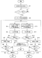
- FIG. 2 is a partial cross-sectional explanatory view showing a structure around a combustion chamber of the gas engine shown in FIG. 1. It is a flowchart of a combustion control apparatus. The return state of the gas fuel by the return means is shown, (A) shows the case of a cylinder other than the knocking cylinder, (B) shows the case of the knocking cylinder, and (C) shows a comparative example. It is explanatory drawing which shows a knocking area
- FIG. 1 shows an overall configuration of a combustion control apparatus for a gas engine according to a first embodiment of the present invention
- FIG. 2 is a partial sectional view around a combustion chamber.
- a gas engine hereinafter simply referred to as an engine
- the crankshaft 2 of the engine 1 is provided with a flywheel 3, and a generator 5 is directly attached to the flywheel 3.
- a gas fuel control device 7 that controls the amount of gas fuel supplied into each cylinder of the engine 1 and an ignition device 9 that ignites the gas fuel supplied into each cylinder are provided.
- a piston 13 slidably fitted in the cylinder 11 a main combustion chamber 17 defined between the upper surface of the piston 13 and the inner surface of the cylinder block 15, the main combustion chamber 17 is provided with an intake port 19 connected to 17, an intake valve 21 for opening and closing the intake port 19, and the like.
- a gas mixer 25 is installed in the supply pipe 23 upstream of the intake port 19, a gas supply pipe 27 is connected, and a gas adjustment valve 29 is provided in the gas supply pipe 27 to adjust the amount of fuel gas.
- the supplied fuel gas and the air supplied through the air supply pipe 23 are premixed by the gas mixer 25. Then, it reaches the intake valve 21 via the intake port 19, and the premixed gas mixture is supplied to the main combustion chamber 17 by opening the intake valve 21.
- the air supply pipe 23, the gas supply pipe 27, the gas regulating valve 29 provided in the gas supply pipe 27, and the gas mixer 25 shown in FIG. 2 are provided for each cylinder.
- an ignition device 9 is provided for each cylinder in the cylinder bed 31 that forms the upper part of the main combustion chamber 17 of each cylinder.
- the ignition device 9 has a structure in which a sub-combustion chamber (sub-chamber) and a spark plug (not shown) are provided.
- the sub-chamber fuel gas supplied to the sub-chamber is ignited by the spark plug, and the sub-chamber is ignited.
- the generated flame is injected into the main combustion chamber 17 to burn the mixed gas in the main combustion chamber 17.
- the ignition device 9 is ignited by an ignition plug at an appropriate timing based on signals from the rotation speed sensor 42, the crank angle sensor 45, and the load sensor 47, and injects a flame into the main combustion chamber 17. Yes.
- an exhaust port 35 is connected to the main combustion chamber 17, and exhaust gas after combustion is discharged from the main combustion chamber 17 by opening the exhaust valve 37.
- An exhaust pipe 39 (not shown) is connected to the downstream side of the exhaust port 35, and an exhaust supercharger (not shown) is attached to the exhaust pipe 39.
- An in-cylinder pressure sensor 41 that detects the in-cylinder pressure in the main combustion chamber 17 is provided for each cylinder, and the flywheel 3 is provided with a rotation speed sensor 42 that detects the engine speed and a crank angle sensor 45.
- the generator 5 is provided with a load sensor 47 for detecting the load of the generator 5, that is, the engine load. Signals from these sensors are input to a combustion control device 43 described later.
- the combustion control device 43 in the engine 1 having the above configuration mainly detects an abnormal combustion state from the change in the in-cylinder pressure in the main combustion chamber 17 of each cylinder based on a signal from the in-cylinder pressure sensor 41, Knocking determination means 49 for determining whether knocking has occurred or not is provided.
- the knocking determination means 49 determines the occurrence of knocking
- the first knocking reduction means 51 that stops or reduces the supply of gas fuel to the knocking occurrence cylinder, and other cylinders other than the knocking occurrence cylinder
- second knocking reducing means 53 for reducing the supply of gas fuel
- knocking reducing means 55 constituted by the second knocking reducing means 55.
- the first knock reduction means 51 stops or reduces the gas fuel for the cylinder in which knocking has occurred. Therefore, the gas fuel is stopped or reduced by controlling the opening of the gas regulating valve 29 provided in the gas supply pipe 27.
- the reduction rate may be set so as to reduce the supply amount at that time by 2 to 3%. Further, since the reduction control becomes complicated, the supply of gas fuel may be uniformly stopped.
- the reduction amount of 2 to 3% is a gas fuel reduction amount necessary for shifting the air-fuel ratio to the lean side in order to suppress knocking.
- the second knocking reduction means 53 reduces the gas fuel to the cylinders other than the knocking cylinder. In this case, since it is a cylinder in which knocking has not occurred, it is not a reduction in gas fuel for shifting the air-fuel ratio to the lean side. In order to prevent overloading by increasing the load sharing of other cylinders (by increasing the load of other cylinders by operating the cover mechanism), the load of the power generation output is reduced.
- the knocking occurrence cylinder The first return means 57 for returning from the stopped or reduced state of the gas fuel to the amount of gas fuel before the occurrence of knocking, and the gas before the torque reduction from the reduced state of the gas fuel in other cylinders other than the knocking occurrence cylinder Second return means 59 for returning to the fuel amount.
- combustion control device 43 further sets the return time in the first return means 57 to be shorter than the return time of the second return means 59, and prioritizes the return of the knocking cylinder to other cylinders that do not generate knocking. Configured to do.
- the cylinder is first restored to the state where knocking has occurred, and if an abnormality does not occur again, that is, after confirming whether or not abnormal combustion such as knocking or misfiring will occur again or while confirming
- the return is also finished for the other cylinders where knocking does not occur. Therefore, the return control can be performed reliably and stably.
- the reduction or return of the gas fuel by the first knocking reduction means 51, the second knocking reduction means 53, the first return means 57, and the second return means 59 of the combustion control device 43 is performed by the gas fuel control device 7. This is done by controlling the opening of the gas regulating valve 29 that constitutes.
- step S2 in-cylinder pressure of each cylinder is detected in step S1.
- step S2 it is determined whether knocking has occurred, and it is determined whether knocking has occurred. The process is repeated until it occurs. If it has occurred, the cylinder in which knocking has occurred is specified in step S3.
- step S4 the amount of gas fuel for the knocking cylinder is reduced or stopped, and the air-fuel ratio is shifted to lean (t0 in the time chart of FIG. 4B). Thereafter, in step S5, the system waits for a certain period of time with the gas amount reduced or stopped (t0 to t1 in the time chart of FIG. 4B).
- step S6 it is determined whether knocking has occurred during the standby. When it is determined in step S6 that knocking has not occurred, in step S7, it is returned at time ta (t1 to t2 in the time chart of FIG. 4B). In the next step S8, it is determined whether or not knocking has occurred during the return operation. If knocking has not occurred in step S8, the process ends in step S9, assuming that the return is complete. If it is determined in step S8 that knocking has occurred, the process returns to step S4 and is repeated.
- step S10 the amount of gas fuel with respect to other cylinders where no knocking occurs is reduced (t0 in the time chart of FIG. 4A).
- This reduction in the amount of gas fuel is set as a reduction amount of gas fuel commensurate with a load reduction of 2 to 3% KW of the power generation output in order to prevent overload.
- step S11 the system waits for a certain time in the gas amount reduced state (t0 to t1 in the time chart of FIG. 4A).
- step S12 it is determined whether knocking has occurred during the standby. If it is determined in step S12 that knocking has not occurred, it is returned over time tb (t1 to t3 in the time chart of FIG. 4A) in step S14. In the next step S15, it is determined whether knocking has occurred during the return operation. If knocking has not occurred in step S15, the process ends in step S16, assuming that the return is complete. If it is determined in step S15 that knocking has occurred, the process returns to step S10 and is repeated.
- the above steps S10 to S16 have the same processing flow as steps S4 to S9.
- step S13 a constant load reduction is performed on all the cylinders and the gas fuel amount is reduced accordingly.
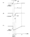
- FIG. 4 shows a return state by the first return means 57 and the second return means 59.
- (A) is for the cylinders other than the knocking cylinder, and shows the case by the second return means 59
- (B) is for the knocking cylinder and shows the case by the first return means 57
- ( C) shows, as a comparative example, an example in which the supply amount of gas fuel is reduced along a constant load reduction for all cylinders.
- the recovery time tb in the present invention, longer than the recovery time ta
- the gas fuel is gradually increased at the time of return from the state where the temperature in the combustion chamber is lowered, and instability of combustion appears and misfire is likely to occur.
- such an unstable return can be avoided by increasing the amount of gas fuel at once at the return time ta (a time shorter than the return time tb).
- the start of return of the first return means 57 and the second return means 59 is started at the same time as t1, but the second return means shown in FIG.
- the start time of 59 may be started from time t2 when the return by the first return means 57 is completed.
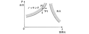
- FIG. 5 shows regions where abnormal combustion (knocking, misfire) of the engine 1 occurs, and shows the respective regions with the air-fuel ratio ⁇ on the horizontal axis and the engine output P on the vertical axis.
- the engine 1 of the present embodiment is operating at a high output and is operated at a substantially constant rotation at the point P1. It is easy to move to the operating point P2 in the knocking region due to fluctuations in power generation load and environmental conditions. When moving to the knocking region, it is necessary to respond from the knocking region to the normal operation region by reducing the output or leaning the air-fuel ratio. In the present embodiment, knocking is avoided by shifting the air-fuel ratio to the lean side by a 2-3% reduction in the amount of gas fuel at the time of operation for the cylinder in which knocking occurs.
- the gas fuel is stopped or reduced for the knocking cylinder, and in the subsequent return control to the optimum operation, the fuel is misfired in order to increase the gas fuel appropriately. It can prevent falling into unstable combustion state.
- the first return means 57 returns the gas fuel from the stopped or reduced state
- the second return means 59 returns the gas fuel from the reduced state in the cylinders other than the knocking cylinder.
- the return time in the first return means 57 is made shorter than the return time of the second return means 59, giving priority to the return of the cylinder in which knocking has occurred, and then the return of other cylinders in which knocking has not occurred. Therefore, the return control can be performed reliably and stably.
- the return control when returning to the optimal operation by increasing the amount again is performed appropriately, and thus misfires, etc. Since it can prevent falling into an unstable combustion state, it is suitable for use in a combustion control device of a gas engine for a generator.
Abstract
Description
安定かつ効率的な運転を行わせるために、各気筒に設けられ燃料供給弁の制御、および着火タイミングの制御を行っているが、ノッキングや失火等の異常燃焼が生じることがある。このノッキングや失火等の異常燃焼を早期に検出して、回避することが必要である。 A power generation facility using a gas engine using natural gas or city gas as a main fuel is installed from the viewpoint of a clean energy source.
In order to perform stable and efficient operation, the fuel supply valve provided in each cylinder is controlled and the ignition timing is controlled. However, abnormal combustion such as knocking or misfire may occur. It is necessary to detect and avoid abnormal combustion such as knocking and misfire at an early stage.
また、同様にパイロット燃料噴射時期における噴射時期について、および火花点火時期の点火時期について、遅らすことおよび進めることが開示されている。 Further,
Similarly, it is disclosed to delay and advance the injection timing at the pilot fuel injection timing and the ignition timing of the spark ignition timing.
これによって、ノッキング発生気筒に対する空燃比がリーン側にシフトしてノッキングの発生が抑えられる。また、ノッキング発生のない他の気筒に対しても、過負荷を防止するために所定の発電出力低下による負荷下げの指示により、ガス燃料が低減される。 According to the present invention, when the occurrence of knocking is determined, the supply of gas fuel to the knocking cylinder is stopped or reduced, and the supply of gas fuel is also reduced to other cylinders that do not generate knocking. .
As a result, the air-fuel ratio for the knocking cylinder is shifted to the lean side, and the occurrence of knocking is suppressed. In addition, the gas fuel is reduced in response to an instruction to reduce the load due to a predetermined decrease in the power generation output in order to prevent overload for the other cylinders in which knocking does not occur.
このため、まずノッキングが発生した気筒を復帰させて、再度異常が発生しなければ、つまり再度ノッキングや、失火等の異常燃焼が再発しないかを確認してから、ノッキング発生のない他の気筒に対しても復帰を終了させるようにできる。従って、復帰制御を確実かつ安定的に行うことができる。 In the knocking occurrence cylinder, the return is caused to recover from the stopped or reduced state of the gas fuel by the first return means, and in the other cylinders other than the knock occurrence cylinder, the second return means is used to return from the reduced state of the gas fuel. . Then, the return time in the first return means is made shorter than the return time in the second return means, and the return of the knocking cylinder is prioritized.
For this reason, first, the cylinder in which knocking has occurred is restored, and if there is no abnormality again, that is, it is confirmed again that abnormal combustion such as knocking or misfiring will not recur, In contrast, the return can be terminated. Therefore, the return control can be performed reliably and stably.
さらに、第1復帰手段を短時間で、例えば復帰制御を開始後2~3秒間で復帰するように設定するとよい。ガス燃料を絞ることで、ノッキング対策は有効にできるが、反面燃焼温度の低下によって燃焼室内温度が低下しているため、復帰時に徐々にガス燃料を増量していくと、燃焼の不安定性が顕著に現れ、失火するおそれがある。このため、一気にガス燃料の増量を実施することで、このような不安定な復帰を回避できる。 Thus, the return time of the first return means can be made shorter than the return time of the second return means by making the increase rate of the gas fuel in the first return means larger than the increase rate of the gas fuel in the second return means. .
Further, the first return means may be set to return in a short time, for example, 2 to 3 seconds after starting the return control. By narrowing down the gas fuel, knocking countermeasures can be effective, but the combustion chamber temperature has decreased due to a decrease in the combustion temperature, so if the gas fuel is gradually increased at the time of recovery, combustion instability becomes significant. May appear and cause a fire. For this reason, such an unstable return can be avoided by increasing the amount of gas fuel at once.
従って、ノッキング発生気筒に対する方がノッキング発生のない他の気筒より大きく設定されることによって、ノッキングの低減制御を効果的に行うことができる。 This is the amount of gas fuel reduction for shifting the air-fuel ratio to the lean side in order to suppress knocking for the cylinder where knocking occurs, and knocking occurs for other cylinders where knocking has not occurred. Assuming that one cylinder is one cylinder, this is a reduction amount associated with a decrease in the load of the power generation output in order to prevent the load sharing of the other cylinders from increasing and the overloading.
Therefore, knocking reduction cylinders can be effectively controlled by setting the cylinders that are knocking larger than other cylinders that are not knocking.
ガス燃料を増量して復帰させる際に、第1復帰手段における復帰時間を第2復帰手段の復帰時間より短くして、ノッキングが発生した気筒の復帰を優先させて終了するようにし、ノッキングの再発を確認してから、ノッキング発生のない他の気筒の復帰を終了させるようにできる。これによって、復帰制御を確実かつ安定的に行うことができる。 That is, the gas fuel is stopped or returned from the reduced state by the first return means, and the gas fuel is returned from the reduced state by the second return means in the cylinders other than the knocking cylinder.
When returning by increasing the amount of gas fuel, the return time of the first return means is made shorter than the return time of the second return means so that the return of the cylinder in which knocking has occurred is prioritized and finished, so that the knocking reoccurs. After confirming the above, it is possible to end the return of the other cylinders in which knocking does not occur. As a result, the return control can be performed reliably and stably.
図1において、ガスエンジン(以下単にエンジンという)1は、天然ガスや都市ガス等のガス燃料を主燃料とする、多気筒4サイクルエンジンである。エンジン1のクランクシャフト2にはフライホイール3が備えられ、フライホイール3には発電機5が直接取り付けられている。
また、エンジン1の各気筒内に供給するガス燃料の供給量を制御するガス燃料制御装置7、および各気筒内に供給されたガス燃料を着火する着火装置9が設けられている。 FIG. 1 shows an overall configuration of a combustion control apparatus for a gas engine according to a first embodiment of the present invention, and FIG. 2 is a partial sectional view around a combustion chamber.
In FIG. 1, a gas engine (hereinafter simply referred to as an engine) 1 is a multi-cylinder four-cycle engine using gas fuel such as natural gas or city gas as a main fuel. The
Further, a gas
そして、吸気ポート19を経て吸気弁21に達し、吸気弁21の開弁によって主燃焼室17に予混合された混合ガスが供給される。
なお、図2に示した給気管23、ガス供給管27、該ガス供給管27に設けられたガス調整弁29、およびガスミキサー25は、それぞれの気筒毎に設けられている。 In addition, a
Then, it reaches the
The
これら各センサからの信号は、後述する燃焼制御装置43に入力されている。 An in-
Signals from these sensors are input to a
燃焼制御装置43は、図1に示すように、主に、前記筒内圧センサ41からの信号を基に各気筒の主燃焼室17内の筒内圧力の変化から燃焼状況が異常燃焼状態、特にノッキングを発生しているか否かを判定するノッキング判定手段49を備えている。 Next, the
As shown in FIG. 1, the
この2~3%の減少量はノッキングを抑制するために、空燃比をリーン側にシフトするために必要なガス燃料低減量である。 For example, when it is determined that knocking has occurred, the reduction rate may be set so as to reduce the supply amount at that time by 2 to 3%. Further, since the reduction control becomes complicated, the supply of gas fuel may be uniformly stopped.
The reduction amount of 2 to 3% is a gas fuel reduction amount necessary for shifting the air-fuel ratio to the lean side in order to suppress knocking.
以上のように、ノッキング発生気筒と、ノッキング発生気筒以外の他の気筒とに対するガス燃料の低減量を異ならして低減することで、効率良いノッキングの抑制効果が得られる。 For example, assuming that one of 18 cylinders is knocked and the supply of gas fuel is stopped while operating at a load of about 50%, the load of the gas fuel is reduced by 2-3% KW of the power generation output. Set as reduction amount.
As described above, an effective knocking suppression effect can be obtained by reducing the amount of reduction in gas fuel for the knocking cylinder and other cylinders other than the knocking cylinder.
まず、運転を開始すると、ステップS1で、各気筒の筒内圧を検出する。ステップS2で、ノッキングの判定を行い、ノッキングが発生しているか否かが判定され、発生するまで繰り返され、発生している場合には、ステップS3で、ノッキング発生気筒を特定する。 Next, the control flow of the
First, when operation is started, in-cylinder pressure of each cylinder is detected in step S1. In step S2, it is determined whether knocking has occurred, and it is determined whether knocking has occurred. The process is repeated until it occurs. If it has occurred, the cylinder in which knocking has occurred is specified in step S3.
ステップS8でノッキングが発生していなければ、ステップS9で復帰は完了したとして終了する。
また、ステップS8でノッキングが発生していると判定すれば、ステップS4に戻って繰り返す。 In step S6, it is determined whether knocking has occurred during the standby. When it is determined in step S6 that knocking has not occurred, in step S7, it is returned at time ta (t1 to t2 in the time chart of FIG. 4B). In the next step S8, it is determined whether or not knocking has occurred during the return operation.
If knocking has not occurred in step S8, the process ends in step S9, assuming that the return is complete.
If it is determined in step S8 that knocking has occurred, the process returns to step S4 and is repeated.
その後、ステップS11で、ガス量低減状態で一定時間待機する(図4(A)のタイムチャートのt0~t1)。 On the other hand, after the knocking occurrence cylinder is specified in step S3, next, in step S10, the amount of gas fuel with respect to other cylinders where no knocking occurs is reduced (t0 in the time chart of FIG. 4A). This reduction in the amount of gas fuel is set as a reduction amount of gas fuel commensurate with a load reduction of 2 to 3% KW of the power generation output in order to prevent overload.
After that, in step S11, the system waits for a certain time in the gas amount reduced state (t0 to t1 in the time chart of FIG. 4A).
ステップS15でノッキングが発生していなければ、ステップS16で復帰は完了したとして終了する。
また、ステップS15でノッキングが発生していると判定すれば、ステップS10に戻って繰り返す。
以上のステップS10~S16は、ステップS4~S9と同様の処理の流れになっている。 In step S12, it is determined whether knocking has occurred during the standby. If it is determined in step S12 that knocking has not occurred, it is returned over time tb (t1 to t3 in the time chart of FIG. 4A) in step S14. In the next step S15, it is determined whether knocking has occurred during the return operation.
If knocking has not occurred in step S15, the process ends in step S16, assuming that the return is complete.
If it is determined in step S15 that knocking has occurred, the process returns to step S10 and is repeated.
The above steps S10 to S16 have the same processing flow as steps S4 to S9.
(A)はノッキング発生気筒以外の他の気筒に対するものであり、第2復帰手段59による場合を示し、(B)はノッキング発生気筒に対するものであり、第1復帰手段57による場合を示し、(C)は比較例として、全気筒に対して一定の負荷下げに沿ったガス燃料の供給量を減少させる例を示す。 FIG. 4 shows a return state by the first return means 57 and the second return means 59.
(A) is for the cylinders other than the knocking cylinder, and shows the case by the second return means 59, (B) is for the knocking cylinder and shows the case by the first return means 57, ( C) shows, as a comparative example, an example in which the supply amount of gas fuel is reduced along a constant load reduction for all cylinders.
本実施形態のように、復帰時間ta(復帰時間tbより短い時間)で一気にガス燃料の増量を実施することで、このような不安定な復帰を回避できる。 In the comparative example of FIG. 4 (C), as shown in the figure, the recovery time tb (in the present invention, longer than the recovery time ta) after the standby time has elapsed after performing a constant load reduction for all cylinders. Therefore, the gas fuel is gradually increased at the time of return from the state where the temperature in the combustion chamber is lowered, and instability of combustion appears and misfire is likely to occur.
As in the present embodiment, such an unstable return can be avoided by increasing the amount of gas fuel at once at the return time ta (a time shorter than the return time tb).
本実施形態のエンジン1は、高出力運転をしており、P1の点で、ほぼ一定回転で運転されている。発電負荷や環境条件の変動等で、ノッキング領域の運転点P2に移動しやすい。ノッキング領域へ移動した場合には、ノッキング領域から通常運転領域へは、出力低下若しくは空燃比のリーン化によって対応する必要がある。
本実施形態では、ノッキング発生気筒に対して、その運転時点のガス燃料量に対して2~3%の減少によって、空燃比をリーン側にシフトして、ノッキングを回避することを行っている。 FIG. 5 shows regions where abnormal combustion (knocking, misfire) of the
The
In the present embodiment, knocking is avoided by shifting the air-fuel ratio to the lean side by a 2-3% reduction in the amount of gas fuel at the time of operation for the cylinder in which knocking occurs.
その復帰の際に、第1復帰手段57における復帰時間を第2復帰手段59の復帰時間より短くし、ノッキングが発生した気筒の復帰を優先し、その次にノッキング発生のない他の気筒の復帰を終了させるようにしているので、復帰制御を確実かつ安定的に行うことができる。 That is, the first return means 57 returns the gas fuel from the stopped or reduced state, and the second return means 59 returns the gas fuel from the reduced state in the cylinders other than the knocking cylinder.
At the time of the return, the return time in the first return means 57 is made shorter than the return time of the second return means 59, giving priority to the return of the cylinder in which knocking has occurred, and then the return of other cylinders in which knocking has not occurred. Therefore, the return control can be performed reliably and stably.
5 発電機
7 ガス燃料制御装置
9 着火装置
41 筒内圧センサ
42 回転数センサ
43 燃焼制御装置
45 クランク角センサ
47 負荷センサ
49 ノッキング判定手段
51 第1ノッキング低減手段
53 第2ノッキング低減手段
55 ノッキング低減手段
57 第1復帰手段
59 第2復帰手段
1 Engine (gas engine)
DESCRIPTION OF
Claims (5)
- ガスエンジンの燃焼制御装置において、
各気筒のノッキングの発生を判定するノッキング判定手段と、
該ノッキング発生判定手段によってノッキングの発生を判定したときに、ノッキング発生気筒に対してガス燃料の供給を停止または減少させるとともに、ノッキング発生のない他の気筒に対してガス燃料の供給を減少させるノッキング低減手段と、
前記停止または減少後にノッキングが発生していないと判定したときに、前記ノッキング発生気筒においてガス燃料の停止または減少状態から復帰させる第1復帰手段と、
前記ノッキング発生気筒以外の他の気筒においてガス燃料の減少状態から復帰させる第2復帰手段と、を備え、
前記第1復帰手段における復帰時間を前記第2復帰手段の復帰時間より短くし、ノッキング発生気筒の復帰を優先して行うことを特徴とするガスエンジンの燃焼制御装置。 In a combustion control device for a gas engine,
Knocking judging means for judging the occurrence of knocking in each cylinder;
Knocking that stops or reduces the supply of gas fuel to the cylinder where knocking occurs and reduces the supply of gas fuel to other cylinders where knocking does not occur when the occurrence of knocking is determined by the knocking generation determination means Reduction means,
First return means for returning from a stopped or reduced state of gas fuel in the knocking occurrence cylinder when it is determined that knocking has not occurred after the stop or reduction;
Second return means for returning from a reduced state of gas fuel in the cylinders other than the knocking cylinder,
A combustion control device for a gas engine, wherein a return time in the first return means is shorter than a return time in the second return means, and the return of the knocking cylinder is prioritized. - 第1復帰手段および第2復帰手段は、前記ノッキング低減手段によってガス燃料を停止または減少した後の所定時間内に、ノッキングの発生がないときに復帰制御を開始するように構成したことを特徴とする請求項1記載のガスエンジンの燃焼制御装置。 The first return means and the second return means are configured to start the return control when there is no knocking within a predetermined time after the fuel gas is stopped or reduced by the knock reduction means. The combustion control device for a gas engine according to claim 1.
- 前記第1復帰手段におけるガス燃料の増加率を、前記第2復帰手段におけるガス燃料の増加率より大きく設定したことを特徴とする請求項1記載のガスエンジンの燃焼制御装置。 2. The combustion control device for a gas engine according to claim 1, wherein an increasing rate of the gas fuel in the first returning means is set larger than an increasing rate of the gas fuel in the second returning means.
- 前記ノッキング低減手段によるガス燃料低減量は、ノッキング発生気筒に対する方がノッキング発生のない他の気筒より大きく設定されることを特徴とする請求項1乃至3の何れか1項記載のガスエンジンの燃焼制御装置。 4. The combustion of a gas engine according to claim 1, wherein the amount of gas fuel reduced by the knocking reducing means is set to be larger with respect to the cylinder where knocking occurs than with other cylinders where knocking does not occur. Control device.
- 前記所定時間内にノッキングが再発した場合に、その時点において前記ノッキング低減手段によって設定されるガス燃料の低減量をさらに付加して低減させることを特徴とする請求項2記載のガスエンジンの燃焼制御装置。 3. The combustion control of a gas engine according to claim 2, wherein when knocking reoccurs within the predetermined time, a reduction amount of the gas fuel set by the knocking reduction means at that time is further added and reduced. apparatus.
Priority Applications (4)
| Application Number | Priority Date | Filing Date | Title |
|---|---|---|---|
| CN201480010866.9A CN105026738B (en) | 2013-03-19 | 2014-02-20 | The combustion control device of gas engine |
| US14/777,470 US9964053B2 (en) | 2013-03-19 | 2014-02-20 | Combustion control device for gas engine |
| EP14768042.5A EP2957753B1 (en) | 2013-03-19 | 2014-02-20 | Fuel control device for gas engine |
| KR1020157025419A KR101755969B1 (en) | 2013-03-19 | 2014-02-20 | Fuel control device for gas engine |
Applications Claiming Priority (2)
| Application Number | Priority Date | Filing Date | Title |
|---|---|---|---|
| JP2013-056776 | 2013-03-19 | ||
| JP2013056776A JP5951537B2 (en) | 2013-03-19 | 2013-03-19 | Gas engine combustion control device |
Publications (1)
| Publication Number | Publication Date |
|---|---|
| WO2014148191A1 true WO2014148191A1 (en) | 2014-09-25 |
Family
ID=51579883
Family Applications (1)
| Application Number | Title | Priority Date | Filing Date |
|---|---|---|---|
| PCT/JP2014/054049 WO2014148191A1 (en) | 2013-03-19 | 2014-02-20 | Fuel control device for gas engine |
Country Status (6)
| Country | Link |
|---|---|
| US (1) | US9964053B2 (en) |
| EP (1) | EP2957753B1 (en) |
| JP (1) | JP5951537B2 (en) |
| KR (1) | KR101755969B1 (en) |
| CN (1) | CN105026738B (en) |
| WO (1) | WO2014148191A1 (en) |
Cited By (3)
| Publication number | Priority date | Publication date | Assignee | Title |
|---|---|---|---|---|
| CN105526013A (en) * | 2014-10-17 | 2016-04-27 | 福特环球技术公司 | If method and system for engine knock control |
| US9964053B2 (en) | 2013-03-19 | 2018-05-08 | Mitsubishi Heavy Industries, Ltd. | Combustion control device for gas engine |
| EP3244048A4 (en) * | 2015-01-08 | 2018-08-22 | Mitsubishi Heavy Industries, Ltd. | Knocking control method |
Families Citing this family (5)
| Publication number | Priority date | Publication date | Assignee | Title |
|---|---|---|---|---|
| US11952935B2 (en) * | 2011-12-16 | 2024-04-09 | Transportation Ip Holdings, Llc | Systems and method for controlling auto-ignition |
| FR3048262B1 (en) * | 2016-02-26 | 2018-03-16 | Peugeot Citroen Automobiles Sa | METHOD FOR LIMITING CHARGE OF A THERMAL MOTOR IN THE EVENT OF DETECTION OF ABNORMAL COMBUSTIONS |
| CN108533413B (en) * | 2017-03-01 | 2020-10-09 | 联合汽车电子有限公司 | Method and system for detecting and optimizing pre-ignition of engine |
| JP2021076029A (en) * | 2019-11-05 | 2021-05-20 | 三菱重工エンジン&ターボチャージャ株式会社 | Gas engine reignition processing device, reignition method and program |
| US20220163005A1 (en) * | 2020-11-23 | 2022-05-26 | Transportation Ip Holdings, Llc | Methods and systems for engine |
Citations (7)
| Publication number | Priority date | Publication date | Assignee | Title |
|---|---|---|---|---|
| JPH03185270A (en) * | 1989-12-15 | 1991-08-13 | Toyota Motor Corp | Ignition control device of internal combustion engine |
| JPH0579440A (en) * | 1991-09-19 | 1993-03-30 | Hitachi Ltd | Ignition timing control device |
| JPH0828319A (en) * | 1994-05-10 | 1996-01-30 | Nippondenso Co Ltd | Fuel injection control device for internal combustion engine |
| JP4247842B2 (en) | 2006-03-16 | 2009-04-02 | 三井造船株式会社 | Gas engine knocking control device |
| JP2009281251A (en) * | 2008-05-21 | 2009-12-03 | Toyota Motor Corp | Ignition timing control device for internal combustion engine |
| JP2010084739A (en) * | 2008-10-02 | 2010-04-15 | Kawasaki Heavy Ind Ltd | Knocking control device for gas engine |
| JP4688916B2 (en) | 2008-10-01 | 2011-05-25 | 川崎重工業株式会社 | Gas engine control device |
Family Cites Families (21)
| Publication number | Priority date | Publication date | Assignee | Title |
|---|---|---|---|---|
| JPS5820374B2 (en) * | 1977-10-11 | 1983-04-22 | 日産自動車株式会社 | Electronically controlled fuel injection device for internal combustion engines |
| US4243009A (en) * | 1979-09-27 | 1981-01-06 | Brunswick Corporation | Detonation control apparatus for outboard motor |
| DE4002207A1 (en) * | 1990-01-26 | 1991-08-01 | Bosch Gmbh Robert | Catalyser protection by detection misfiring cylinder detection - cutting of fuel to misfiring cylinder and making fuel mixt. to remaining cylinders leaner |
| DE19709395C2 (en) * | 1997-03-07 | 1998-12-24 | Bosch Gmbh Robert | Knock control method in multi-cylinder internal combustion engines |
| DE19908729A1 (en) * | 1999-03-01 | 2000-09-07 | Bosch Gmbh Robert | Fuel injection method for an internal combustion engine |
| US6662788B2 (en) * | 2002-04-16 | 2003-12-16 | Lance E. Nist | Remote metering for gaseous fuels and oxidizers |
| US6863034B2 (en) * | 2003-01-17 | 2005-03-08 | Robert D. Kern | Method of controlling a bi-fuel generator set |
| US7533634B2 (en) * | 2004-03-10 | 2009-05-19 | Tgi, Inc. | Process for use with dual-fuel systems |
| FI119395B (en) | 2004-03-15 | 2008-10-31 | Waertsilae Finland Oy | Adaptive load balancing system |
| JP4424178B2 (en) * | 2004-11-30 | 2010-03-03 | スズキ株式会社 | Misfire detection system for multi-cylinder engines |
| JP2006183548A (en) * | 2004-12-27 | 2006-07-13 | Nippon Soken Inc | Control device for internal combustion engine |
| JP4466864B2 (en) | 2005-09-21 | 2010-05-26 | 三菱自動車工業株式会社 | Control device for internal combustion engine |
| JP3968112B2 (en) * | 2006-01-11 | 2007-08-29 | ヤンマー株式会社 | Control method of sub chamber type gas engine |
| US7302932B2 (en) * | 2006-03-17 | 2007-12-04 | Ford Global Technologies, Llc | Pre-ignition detection and mitigation |
| US7665452B2 (en) * | 2006-03-17 | 2010-02-23 | Ford Global Technologies, Llc | First and second spark plugs for improved combustion control |
| JP2010112244A (en) * | 2008-11-05 | 2010-05-20 | Fujitsu Ten Ltd | Control device and control method |
| JP2011185142A (en) * | 2010-03-08 | 2011-09-22 | Toyota Motor Corp | Controller of multi-cylinder internal combustion engine |
| WO2012057691A1 (en) | 2010-10-29 | 2012-05-03 | Afv Alternative Fuel Vehicle | Dual fuel engine system |
| JP5675466B2 (en) * | 2011-03-31 | 2015-02-25 | 三菱重工業株式会社 | Pilot injection timing control method and apparatus when engine combustion diagnosis signal is abnormal |
| US9038596B2 (en) * | 2011-12-02 | 2015-05-26 | Ford Global Technologies, Llc | Method and system for pre-ignition control |
| JP5951537B2 (en) | 2013-03-19 | 2016-07-13 | 三菱重工業株式会社 | Gas engine combustion control device |
-
2013
- 2013-03-19 JP JP2013056776A patent/JP5951537B2/en active Active
-
2014
- 2014-02-20 WO PCT/JP2014/054049 patent/WO2014148191A1/en active Application Filing
- 2014-02-20 CN CN201480010866.9A patent/CN105026738B/en active Active
- 2014-02-20 US US14/777,470 patent/US9964053B2/en active Active
- 2014-02-20 EP EP14768042.5A patent/EP2957753B1/en active Active
- 2014-02-20 KR KR1020157025419A patent/KR101755969B1/en active IP Right Grant
Patent Citations (7)
| Publication number | Priority date | Publication date | Assignee | Title |
|---|---|---|---|---|
| JPH03185270A (en) * | 1989-12-15 | 1991-08-13 | Toyota Motor Corp | Ignition control device of internal combustion engine |
| JPH0579440A (en) * | 1991-09-19 | 1993-03-30 | Hitachi Ltd | Ignition timing control device |
| JPH0828319A (en) * | 1994-05-10 | 1996-01-30 | Nippondenso Co Ltd | Fuel injection control device for internal combustion engine |
| JP4247842B2 (en) | 2006-03-16 | 2009-04-02 | 三井造船株式会社 | Gas engine knocking control device |
| JP2009281251A (en) * | 2008-05-21 | 2009-12-03 | Toyota Motor Corp | Ignition timing control device for internal combustion engine |
| JP4688916B2 (en) | 2008-10-01 | 2011-05-25 | 川崎重工業株式会社 | Gas engine control device |
| JP2010084739A (en) * | 2008-10-02 | 2010-04-15 | Kawasaki Heavy Ind Ltd | Knocking control device for gas engine |
Non-Patent Citations (1)
| Title |
|---|
| See also references of EP2957753A4 |
Cited By (4)
| Publication number | Priority date | Publication date | Assignee | Title |
|---|---|---|---|---|
| US9964053B2 (en) | 2013-03-19 | 2018-05-08 | Mitsubishi Heavy Industries, Ltd. | Combustion control device for gas engine |
| CN105526013A (en) * | 2014-10-17 | 2016-04-27 | 福特环球技术公司 | If method and system for engine knock control |
| CN105526013B (en) * | 2014-10-17 | 2020-12-04 | 福特环球技术公司 | Judgment method and system for engine knock control |
| EP3244048A4 (en) * | 2015-01-08 | 2018-08-22 | Mitsubishi Heavy Industries, Ltd. | Knocking control method |
Also Published As
| Publication number | Publication date |
|---|---|
| EP2957753A4 (en) | 2016-03-09 |
| US9964053B2 (en) | 2018-05-08 |
| JP2014181615A (en) | 2014-09-29 |
| EP2957753B1 (en) | 2017-08-30 |
| US20160032847A1 (en) | 2016-02-04 |
| EP2957753A1 (en) | 2015-12-23 |
| CN105026738A (en) | 2015-11-04 |
| KR101755969B1 (en) | 2017-07-19 |
| CN105026738B (en) | 2017-10-20 |
| KR20150119356A (en) | 2015-10-23 |
| JP5951537B2 (en) | 2016-07-13 |
Similar Documents
| Publication | Publication Date | Title |
|---|---|---|
| JP5951537B2 (en) | Gas engine combustion control device | |
| JP4247842B2 (en) | Gas engine knocking control device | |
| JP2012002088A (en) | Control device of internal combustion engine | |
| JP4893499B2 (en) | In-cylinder direct injection spark ignition internal combustion engine control device and control method | |
| JP4765745B2 (en) | Ignition timing control system for internal combustion engine | |
| JP2008095539A (en) | Premixed compression ignition internal combustion engine | |
| JP2006144645A (en) | Control device and control method of internal combustion engine | |
| JP6467170B2 (en) | Engine control apparatus equipped with turbocharger and control method using the same | |
| JP2010127175A (en) | Combustion control device of diesel engine | |
| JP2015014229A (en) | Abnormal combustion avoidance device for internal combustion engine | |
| JP2008002303A (en) | Misfire time output or load limiting operation method of engine and its device | |
| JP2021067223A (en) | Internal combustion engine controller | |
| JP2014173497A (en) | Internal combustion engine ignition timing control device | |
| JP4803117B2 (en) | Start control device for internal combustion engine | |
| JP2010127087A (en) | Combustion control device of internal combustion engine | |
| JP2007278088A (en) | Fuel injection control device for internal combustion engine | |
| JP4454433B2 (en) | Ignition timing control method for internal combustion engine | |
| JP2009138673A (en) | Ignition control system for internal combustion engine | |
| JP2007263043A (en) | Combustion control system of internal combustion engine | |
| JPH08177589A (en) | Combustion control method for cylinder injection engine | |
| JP5652579B1 (en) | Control device and control method for internal combustion engine | |
| KR20190073175A (en) | Noise reduction system of engine | |
| JP2008267292A (en) | Control system of internal combustion engine | |
| JP2018091272A (en) | Control device of internal combustion engine | |
| WO2016035173A1 (en) | Fuel-responsive control device and fuel-responsive control method for variable compression ratio-type internal combustion engine |
Legal Events
| Date | Code | Title | Description |
|---|---|---|---|
| WWE | Wipo information: entry into national phase |
Ref document number: 201480010866.9 Country of ref document: CN |
|
| 121 | Ep: the epo has been informed by wipo that ep was designated in this application |
Ref document number: 14768042 Country of ref document: EP Kind code of ref document: A1 |
|
| REEP | Request for entry into the european phase |
Ref document number: 2014768042 Country of ref document: EP |
|
| WWE | Wipo information: entry into national phase |
Ref document number: 2014768042 Country of ref document: EP |
|
| WWE | Wipo information: entry into national phase |
Ref document number: 14777470 Country of ref document: US |
|
| ENP | Entry into the national phase |
Ref document number: 20157025419 Country of ref document: KR Kind code of ref document: A |
|
| NENP | Non-entry into the national phase |
Ref country code: DE |