JP4893499B2 - In-cylinder direct injection spark ignition internal combustion engine control device and control method - Google Patents
In-cylinder direct injection spark ignition internal combustion engine control device and control method Download PDFInfo
- Publication number
- JP4893499B2 JP4893499B2 JP2007167204A JP2007167204A JP4893499B2 JP 4893499 B2 JP4893499 B2 JP 4893499B2 JP 2007167204 A JP2007167204 A JP 2007167204A JP 2007167204 A JP2007167204 A JP 2007167204A JP 4893499 B2 JP4893499 B2 JP 4893499B2
- Authority
- JP
- Japan
- Prior art keywords
- speed
- engine
- catalyst
- temperature
- ignition timing
- Prior art date
- Legal status (The legal status is an assumption and is not a legal conclusion. Google has not performed a legal analysis and makes no representation as to the accuracy of the status listed.)
- Expired - Fee Related
Links
- 238000002485 combustion reaction Methods 0.000 title claims description 123
- 238000002347 injection Methods 0.000 title claims description 92
- 239000007924 injection Substances 0.000 title claims description 92
- 238000000034 method Methods 0.000 title claims description 12
- 239000000446 fuel Substances 0.000 claims description 101
- 239000003054 catalyst Substances 0.000 claims description 39
- 230000006835 compression Effects 0.000 claims description 30
- 238000007906 compression Methods 0.000 claims description 30
- 230000003197 catalytic effect Effects 0.000 description 19
- 230000007423 decrease Effects 0.000 description 13
- 239000007789 gas Substances 0.000 description 12
- 230000009467 reduction Effects 0.000 description 5
- 230000001276 controlling effect Effects 0.000 description 4
- 230000003247 decreasing effect Effects 0.000 description 4
- 230000006866 deterioration Effects 0.000 description 4
- 230000008569 process Effects 0.000 description 4
- 239000007921 spray Substances 0.000 description 4
- 239000007858 starting material Substances 0.000 description 4
- 230000003111 delayed effect Effects 0.000 description 3
- 239000000203 mixture Substances 0.000 description 3
- 230000004044 response Effects 0.000 description 3
- 238000011144 upstream manufacturing Methods 0.000 description 3
- 230000002238 attenuated effect Effects 0.000 description 2
- 230000008859 change Effects 0.000 description 2
- 238000001514 detection method Methods 0.000 description 2
- 230000000694 effects Effects 0.000 description 2
- 238000004880 explosion Methods 0.000 description 2
- 230000006872 improvement Effects 0.000 description 2
- 230000001105 regulatory effect Effects 0.000 description 2
- 230000000979 retarding effect Effects 0.000 description 2
- 230000035945 sensitivity Effects 0.000 description 2
- 230000003685 thermal hair damage Effects 0.000 description 2
- XLYOFNOQVPJJNP-UHFFFAOYSA-N water Substances O XLYOFNOQVPJJNP-UHFFFAOYSA-N 0.000 description 2
- 230000004913 activation Effects 0.000 description 1
- 230000015556 catabolic process Effects 0.000 description 1
- 239000000919 ceramic Substances 0.000 description 1
- 239000000567 combustion gas Substances 0.000 description 1
- 238000009841 combustion method Methods 0.000 description 1
- 239000000498 cooling water Substances 0.000 description 1
- 230000006378 damage Effects 0.000 description 1
- 238000006731 degradation reaction Methods 0.000 description 1
- 230000000994 depressogenic effect Effects 0.000 description 1
- 238000010586 diagram Methods 0.000 description 1
- 239000008240 homogeneous mixture Substances 0.000 description 1
- 238000012986 modification Methods 0.000 description 1
- 230000004048 modification Effects 0.000 description 1
- 230000004043 responsiveness Effects 0.000 description 1
Images


Classifications
-
- Y02T10/146—
-
- Y02T10/46—
Description
この発明は、筒内に直接燃料を噴射する燃料噴射弁と筒内の混合気を火花点火する点火プラグとを備える筒内直接噴射式火花点火内燃機関に関し、特に、排気系の触媒コンバータの早期昇温が要求される冷間始動時のアイドル回転速度制御に関する。 The present invention relates to an in-cylinder direct injection spark ignition internal combustion engine including a fuel injection valve that directly injects fuel into a cylinder and an ignition plug that sparks and ignites an air-fuel mixture in the cylinder. The present invention relates to idle rotation speed control at a cold start where a temperature increase is required.
特許文献1に記載されているように、内燃機関のアイドル運転時には、機関回転速度が目標アイドル回転速度と一致するように、吸入空気量を調整するためのスロットル開度をフィードバック制御する、いわゆるアイドル回転速度制御(以下、ISC制御と呼ぶ)が行われる。
As described in
また、本出願人による特許文献2には、筒内直接噴射式火花点火内燃機関における触媒暖機手法として、触媒の早期昇温が要求される触媒昇温時に、点火時期を圧縮上死点(TDC)以降に設定するとともに、燃料噴射時期をTDC以降で点火時期前とする、いわゆる超リタード燃焼を行う技術が記載されている。
上記の超リタード燃焼は、点火時期をTDC以降にリタードすることで燃焼速度を低下させて燃焼効率を低下させることで排気通路中での燃焼により排気温度の上昇を図る技術である。このような超リタード燃焼は、燃料噴射時期や点火時期を圧縮上死点前とする通常燃焼に比して、燃焼効率の低下によるトルク低下を補償するためにアイドル運転でのスロットル開度が大きなものとなる。 The above super retarded combustion is a technique for increasing the exhaust temperature by combustion in the exhaust passage by reducing the combustion speed by retarding the ignition timing after TDC and reducing the combustion efficiency. Such super retard combustion has a large throttle opening in idling operation to compensate for torque reduction due to a decrease in combustion efficiency, compared to normal combustion in which fuel injection timing and ignition timing are before compression top dead center. It will be a thing.
また、超リタード燃焼では、元々排気温度が非常に高いために、補機負荷の増加等に応じて燃料噴射量や吸入空気量を増加させると、燃焼量が更に増加して排気温度が更に高くなってしまう。このため、触媒コンバータの温度が過度に高くなり、熱的損傷や劣化を生じる懸念がある。 In addition, since the exhaust temperature is originally very high in the super retard combustion, if the fuel injection amount or the intake air amount is increased in accordance with an increase in the load on the auxiliary equipment, the combustion amount is further increased and the exhaust temperature is further increased. turn into. For this reason, there is a concern that the temperature of the catalytic converter becomes excessively high, causing thermal damage and deterioration.
本発明は、このような課題に鑑みてなされたものであり、超リタード燃焼を行う筒内直接噴射式火花点火内燃機関でのアイドル運転を安定して良好に行うことを主たる目的としている。 The present invention has been made in view of such problems, and has as its main object to stably and satisfactorily perform idle operation in an in-cylinder direct injection spark ignition internal combustion engine that performs super retard combustion.
本発明は、吸気通路に設けられて燃焼室への吸入空気量を調整するスロットル弁と、筒内に直接燃料を噴射する燃料噴射弁と、点火プラグと、排気通路に設けられる触媒と、を備えた筒内直接噴射式火花点火内燃機関の制御装置において、内燃機関の冷機始動時のように、排気ガスを浄化するために排気通路に設けられる触媒の昇温が要求される触媒昇温時では、触媒昇温手段により点火時期を圧縮上死点後に設定して排気温度を上昇させる。
ここで、前記触媒昇温時以外のアイドル運転時には、第1のアイドル回転速度制御手段により、前記スロットル弁のスロットル開度を調整して、機関回転速度を目標アイドル回転速度にフィードバック制御する。一方、触媒昇温時におけるアイドル運転時には、第1のアイドル回転速度制御手段のように補機負荷の増加等に応じて燃料噴射量や吸入空気量を増加させると、内燃機関の燃焼量が更に増加して排気温度が更に高くなってしまう。そして、この超リタード燃焼時の更なる燃焼量の増加は触媒にダメージを与えるおそれがある。そこで、前記触媒昇温時でのアイドル運転時には、前記第1のアイドル回転速度制御手段のように機関回転速度を目標アイドル回転速度へフィードバック制御するためにスロットル開度を開き側へ調整することを禁止して、第2のアイドル回転速度制御手段により、機関回転速度が目標アイドル回転速度よりも高い場合には、機関回転速度と目標アイドル回転速度との偏差に応じてスロットル開度を調整し、機関回転速度が目標アイドル回転速度よりも低い場合には、機関回転速度と目標アイドル回転速度との偏差に応じて点火時期を調整して機関回転速度を目標アイドル回転速度にフィードバック制御する。
The present invention includes a throttle valve that is provided in an intake passage and adjusts an intake air amount into a combustion chamber, a fuel injection valve that injects fuel directly into a cylinder, an ignition plug, and a catalyst that is provided in an exhaust passage. In the cylinder direct injection type spark ignition internal combustion engine control apparatus provided, when the temperature of the catalyst is increased, the temperature of the catalyst provided in the exhaust passage is required to purify the exhaust gas, such as when the internal combustion engine is cold-started. Then, the ignition temperature is set after the compression top dead center by the catalyst temperature raising means to raise the exhaust gas temperature.
Here, during idle operation other than when the temperature of the catalyst is raised, the throttle opening of the throttle valve is adjusted by the first idle rotation speed control means, and the engine rotation speed is feedback controlled to the target idle rotation speed. On the other hand, during the idling operation when the catalyst temperature rises, if the fuel injection amount or the intake air amount is increased according to an increase in the auxiliary load as in the first idle speed control means, the combustion amount of the internal combustion engine is further increased. As a result, the exhaust temperature becomes higher. And the further increase in the amount of combustion at the time of super retard combustion may damage the catalyst. Therefore, during the idling operation at the time of the catalyst temperature rise, the throttle opening is adjusted to the open side in order to feedback control the engine speed to the target idling speed as in the first idling speed control means. Forbidden, when the engine speed is higher than the target idle speed by the second idle speed control means, the throttle opening is adjusted according to the deviation between the engine speed and the target idle speed, When the engine rotational speed is lower than the target idle rotational speed, the ignition timing is adjusted according to the deviation between the engine rotational speed and the target idle rotational speed, and the engine rotational speed is feedback controlled to the target idle rotational speed.
この発明によれば、超リタード燃焼による触媒昇温時でのアイドル運転時に、補機負荷の増加等に起因する機関回転速度の落込みに対し、機関回転速度を目標アイドル回転速度へフィードバック制御するために、スロットル開度を増加させることなく、点火時期の進角によりトルクを上昇させて機関回転速度を目標アイドル回転速度へ復帰させることができ、スロットル開度の増加による燃焼量の増加を抑制して触媒の熱劣化を抑制できる。 According to the present invention, the engine speed is feedback-controlled to the target idle speed in response to a drop in the engine speed caused by an increase in auxiliary load or the like during idling when the temperature of the catalyst is raised by super retard combustion. Therefore, without increasing the throttle opening, the engine speed can be returned to the target idle speed by increasing the torque by the advance of the ignition timing, and the increase in the combustion amount due to the increase in the throttle opening is suppressed. Thus, thermal deterioration of the catalyst can be suppressed.
尚、超リタード燃焼では、点火時期が既に大幅に遅角されているために、超リタード燃焼以外の状況で点火時期を進角させるのに比してトルク感度が高い。このため、補機負荷等による回転速度の落ち込みに対し、点火時期の進角によって目標アイドル回転速度へ速やかに復帰させることができ、応答性にも優れている。 In the super retard combustion, since the ignition timing has already been greatly retarded, the torque sensitivity is higher than in the case where the ignition timing is advanced in a situation other than the super retard combustion. For this reason, it is possible to quickly return to the target idle rotation speed by the advance of the ignition timing with respect to the drop in the rotation speed due to the auxiliary load or the like, and the response is excellent.
以下、この発明の好ましい実施形態を図面に基づいて詳細に説明する。 Hereinafter, preferred embodiments of the present invention will be described in detail with reference to the drawings.
図1は、この発明の一実施形態に係る筒内直接噴射式火花点火内燃機関のシステム構成図である。内燃機関1はシリンダとシリンダヘッドとピストン2とにより燃焼室3が区画形成される。燃焼室3には、吸気弁(図示せず)を介して吸気通路4が接続され、かつ排気弁(図示せず)を介して排気通路5が接続されている。吸気通路4には、吸入空気量を検出するエアフロメータ6が配設されているとともに、制御信号によりアクチュエータ8を介して開度制御される電子制御スロットル弁7が配設されている。排気通路5には、排気浄化用の触媒コンバータ10が配設されているとともに、その上流側および下流側にそれぞれ空燃比センサ11,12が設けられる。
さらに、上流側の空燃比センサ11と並んで、触媒コンバータ10入口側での排気温度を検出する排気温度センサ13が設けられている。更に本実施形態では、触媒コンバータ10の温度状態を検出するために、該触媒コンバータ10のモノリス型セラミックス触媒担体の長手方向中央部に配置された触媒温度センサ31と、触媒コンバータ10の出口部に配置された触媒出口温度センサ32と、を備えている。
FIG. 1 is a system configuration diagram of a direct injection type spark ignition internal combustion engine according to an embodiment of the present invention. In the
Further, an exhaust
燃焼室3の中央頂上部には、混合気を火花点火する点火プラグ14が配置されている。また、燃焼室3の吸気通路4側の側部に、該燃焼室3内に燃料を直接噴射する燃料噴射弁15が配置されている。この燃料噴射弁15には、高圧燃料ポンプ16およびプレッシャレギュレータ17によって所定圧力に調圧された燃料が、高圧燃料通路18を介して供給されている。従って、各気筒の燃料噴射弁15が制御パルスにより開弁することで、その開弁期間と調圧された燃圧とに応じた量の燃料が噴射される。なお、19は、燃圧を検出する燃圧センサ、20は、上記高圧燃料ポンプ16へ燃料を送る低圧燃料ポンプである。また内燃機関1には、機関冷却水温を検出する水温センサ21が設けられているとともに、クランク角を検出するクランク角センサ22が設けられている。さらに、運転者によるアクセルペダル踏み込み量を検出するアクセル開度センサ23が設けられている。
A
上記内燃機関1の燃料噴射量や噴射時期、点火時期、等は、コントロールユニット25によって制御される。このコントロールユニット25には、上述した各種のセンサ類の検出信号が入力されている。コントロールユニット25は、これらの入力信号により検出される機関運転条件に応じて、燃焼方式つまり均質燃焼とするか成層燃焼とするかを決定するとともに、これに合わせて、電子制御スロットル弁7の開度、燃料噴射弁15の燃料噴射時期および燃料噴射量、点火プラグ14の点火時期、等を制御する。なお、触媒10の早期昇温完了後においては、低速低負荷側の領域では、通常の成層燃焼運転が行われ、高速高負荷側の領域では、通常の均質燃焼運転が行われる。
通常の成層燃焼運転では、圧縮行程の適宜な時期に燃料噴射が行われ、かつ圧縮上死点前の時期に点火が行われる。燃料噴霧は点火プラグ14近傍に層状に集められ、これにより、空燃比を30〜40程度とした極リーンの成層燃焼が実現される。また、通常の均質燃焼運転では、吸気行程中に燃料噴射が行われ、かつ圧縮上死点前のMBT点近傍において点火が行われる。この場合は、燃料は筒内で均質な混合気となる。この均質燃焼運転としては、運転条件に応じて、空燃比を理論空燃比とした均質ストイキ燃焼と、空燃比を20〜30程度のリーンとした均質リーン燃焼と、がある。
The fuel injection amount, injection timing, ignition timing, etc. of the
In a normal stratified combustion operation, fuel injection is performed at an appropriate time in the compression stroke, and ignition is performed at a time before the compression top dead center. The fuel spray is collected in the vicinity of the
一方、触媒コンバータ10の早期昇温が要求される内燃機関1の冷間始動時等の触媒昇温時には、排気温度を高温とするように、超リタード燃焼が行われる。この超リタード燃焼では、燃焼ガスを排気通路中で後燃えさせるために、燃料噴射時期(複数回噴射の場合には少なくとも最後の燃料噴射時期)と点火時期とを圧縮上死点より遅角することで排気ガス温度(単に「排気温度」とも呼ぶ)、ひいては触媒温度を昇温する。触媒コンバータ10を早期に昇温させることを考慮するとリタード量を大きくする程排気温度は上昇する。しかしながら、燃料噴射時期・点火時期のリタード量が大きくなると燃焼安定性が悪化するため、燃焼安定性が許容されるリタード量を設定する。
このとき、燃料噴射時期・点火時期をリタードさせると燃焼効率が悪化するために通常の燃料噴射時期・点火時期に比してトルクが小さくなる。そこで、このトルクの減少を吸入空気量を増加させて燃料噴射量を増量することで補償している。この吸入空気量の増加は、電子制御スロットル弁7を制御することにより行われ、吸入空気量の増加に応じて燃料噴射量が増量される。
超リタード燃焼の実行条件が成立すると実際の制御は次のように行われる。まず、燃料噴射時期と点火時期の燃焼安定性が許容されるリタード限界に設定した場合のトルク低下を補償するスロットル開度を設定する。このスロットル開度は機関回転速度と負荷のマップにより設定されており、燃料噴射時期と点火時期を燃焼安定性が許容されるリタード限界に設定した際に機関回転速度を目標アイドル回転速度に維持できる開度である。そして、スロットル開度を上記のように設定すると、スロットル開度の変更による空気の応答遅れを考慮して燃料噴射時期と点火時期とを燃焼安定性が許容されるリタード限界へ設定する。
この超リタード燃焼の燃料噴射時期および点火時期を図2に基づいて説明する。図2は、超リタード燃焼の3つの実施例を示しており、実施例1では、点火時期を15°〜30°ATDC(例えば20°ATDC)とし、燃料噴射時期(詳しくは燃料噴射開始時期)を、圧縮上死点以降でかつ点火時期前に設定する。なお、このとき、空燃比は、理論空燃比ないしはこれよりも若干リーン(16〜17程度)に設定される。
On the other hand, when the temperature of the catalyst is raised, such as during a cold start of the
At this time, if the fuel injection timing / ignition timing is retarded, the combustion efficiency deteriorates, so that the torque becomes smaller than the normal fuel injection timing / ignition timing. Therefore, this decrease in torque is compensated by increasing the intake air amount to increase the fuel injection amount. The increase in the intake air amount is performed by controlling the electronic control throttle valve 7, and the fuel injection amount is increased in accordance with the increase in the intake air amount.
When the super retard combustion execution condition is satisfied, the actual control is performed as follows. First, a throttle opening is set to compensate for a torque drop when the retard limit is set to allow the combustion stability of the fuel injection timing and the ignition timing. The throttle opening is set by a map of engine speed and load, and the engine speed can be maintained at the target idle speed when the fuel injection timing and the ignition timing are set to the retard limits where the combustion stability is allowed. Opening degree. When the throttle opening is set as described above, the fuel injection timing and the ignition timing are set to the retard limit at which the combustion stability is allowed in consideration of the response delay of the air due to the change in the throttle opening.
The fuel injection timing and ignition timing of this super retard combustion will be described with reference to FIG. FIG. 2 shows three examples of super retard combustion. In Example 1, the ignition timing is set to 15 ° to 30 ° ATDC (for example, 20 ° ATDC), and the fuel injection timing (specifically, the fuel injection start timing) is shown. Is set after the compression top dead center and before the ignition timing. At this time, the air-fuel ratio is set to the stoichiometric air-fuel ratio or slightly lean (about 16 to 17).
すなわち、触媒暖機促進ならびにHC低減のためには、点火時期遅角が有効であり、上死点以降の点火(ATDC点火)が望ましいが、ATDC点火で安定した燃焼を行わせるためには、燃焼期間を短縮する必要があり、そのためには、乱れによる火炎伝播を促進しなければならない。前述したように、圧縮上死点以降では、吸気行程や圧縮行程で生成された乱れは減衰してしまうが、本実施形態では、圧縮上死点以降の膨張行程中になされる高圧の燃料噴射によって、ガス流動が生じ、これにより筒内の乱れを生成・強化することができる。従って、ATDC点火での火炎伝播が促進され、安定した燃焼が可能となる。 That is, in order to promote catalyst warm-up and reduce HC, ignition timing retardation is effective, and ignition after top dead center (ATDC ignition) is desirable, but in order to perform stable combustion with ATDC ignition, It is necessary to shorten the combustion period, and for this purpose, flame propagation due to turbulence must be promoted. As described above, the turbulence generated in the intake stroke and the compression stroke is attenuated after the compression top dead center, but in this embodiment, the high-pressure fuel injection performed during the expansion stroke after the compression top dead center. As a result, a gas flow is generated, and thereby, turbulence in the cylinder can be generated and strengthened. Therefore, flame propagation by ATDC ignition is promoted and stable combustion is possible.
図2の実施例2は、燃料噴射を2回に分割した例であり、1回目の燃料噴射を吸気行程中に行い、2回目の燃料噴射を圧縮上死点以降に行う。なお、点火時期は2回目の燃料噴射に併せて行うため、実施例1と同様の点火時期15°〜30°ATDC(例えば20°ATDC)となる。また、2回の燃料噴射のトータル量は、実施例1の燃料噴射量と同量であるため、トータルの空燃比も実施例1と同様に理論空燃比ないしはこれよりも若干リーン(16〜17程度)となる。 The second embodiment in FIG. 2 is an example in which the fuel injection is divided into two, and the first fuel injection is performed during the intake stroke, and the second fuel injection is performed after the compression top dead center. Since the ignition timing is performed in conjunction with the second fuel injection, the ignition timing is 15 ° to 30 ° ATDC (for example, 20 ° ATDC) similar to that in the first embodiment. In addition, since the total amount of the two fuel injections is the same as the fuel injection amount of the first embodiment, the total air-fuel ratio is the same as in the first embodiment, or the stoichiometric air-fuel ratio or slightly leaner (16 to 17). Degree).
このように、圧縮上死点後の燃料噴射(膨張行程噴射)に先立ち、吸気行程中に燃料噴射(吸気行程噴射)を行うと、吸気行程噴射の燃料噴霧による乱れは圧縮行程後半で減衰してしまい、圧縮上死点後におけるガス流動強化には殆ど影響を与えないが、噴射燃料が燃焼室全体に拡散していて、ATDC点火によるHCの後燃えの促進に寄与するので、HC低減および排温上昇には有効である。 As described above, when fuel injection (intake stroke injection) is performed during the intake stroke prior to fuel injection after the compression top dead center (expansion stroke injection), disturbance due to fuel spray in the intake stroke injection is attenuated in the latter half of the compression stroke. However, since the injected fuel is diffused throughout the combustion chamber and contributes to the promotion of HC afterburning by ATDC ignition, the HC reduction and It is effective for raising the exhaust temperature.
また、図2の実施例3は、燃料噴射を2回に分割し、1回目の燃料噴射を圧縮行程に行い、2回目の燃料噴射を圧縮上死点以降に行う。このように、圧縮上死点後の燃料噴射(膨張行程噴射)に先立ち、圧縮行程中に燃料噴射(圧縮行程噴射)を行うと、実施例2の吸気行程噴射に比べれば、圧縮行程噴射の方が、その燃料噴霧による乱れの減衰が遅くなる。このため、1回目の燃料噴射による乱れが残り、圧縮上死点以降に2回目の燃料噴射を行うことで、1回目の燃料噴射で生成した乱れを助長するように乱れを強化でき、圧縮上死点付近における更なるガス流動強化が図れる。この実施例3の場合に、1回目の圧縮行程噴射は、圧縮行程前半でもよいが、圧縮行程後半(90°BTDC以降)に設定すると、上死点付近での乱れをより高めることができる。特に、この1回目の圧縮行程噴射を、45°BTDC以降、より望ましくは20°BTDC以降とすると、圧縮上死点以降のガス流動をより強化することができる。 In the third embodiment of FIG. 2, the fuel injection is divided into two times, the first fuel injection is performed in the compression stroke, and the second fuel injection is performed after the compression top dead center. As described above, when the fuel injection (compression stroke injection) is performed during the compression stroke prior to the fuel injection after the compression top dead center (expansion stroke injection), the compression stroke injection is compared with the intake stroke injection of the second embodiment. However, the decay of the turbulence due to the fuel spray becomes slower. For this reason, the disturbance due to the first fuel injection remains, and by performing the second fuel injection after the compression top dead center, the disturbance can be strengthened so as to promote the disturbance generated by the first fuel injection. The gas flow can be further strengthened near the dead center. In the case of Example 3, the first compression stroke injection may be in the first half of the compression stroke, but if it is set in the second half of the compression stroke (after 90 ° BTDC), the disturbance near the top dead center can be further increased. In particular, if the first compression stroke injection is 45 ° BTDC or later, more desirably 20 ° BTDC or later, the gas flow after compression top dead center can be further enhanced.
このように、実施例1〜3の超リタード燃焼によれば、点火の直前に燃料噴霧により筒内の乱れを生成・強化することができ、火炎伝播を促進するので、点火時期がリタードすることによる燃焼安定性の悪化を抑制して安定した燃焼を行わせることができる。特に、点火時期を15°〜30°ATDCまで遅角させることにより、触媒の早期昇温およびHC低減のための十分な後燃え効果を得ることができる。換言すれば、このように点火時期を大きく遅らせても、その直前まで燃料噴射を遅らせて、乱れの生成時期も遅らせることで、火炎伝播向上による燃焼改善を達成できるのである。 As described above, according to the super retarded combustion of the first to third embodiments, the turbulence in the cylinder can be generated and strengthened by the fuel spray immediately before ignition, and the flame propagation is promoted, so that the ignition timing is retarded. It is possible to suppress the deterioration of the combustion stability due to, and to perform stable combustion. In particular, by retarding the ignition timing from 15 ° to 30 ° ATDC, it is possible to obtain a sufficient afterburning effect for rapid catalyst temperature rise and HC reduction. In other words, even if the ignition timing is greatly delayed in this way, the fuel injection is delayed until just before that, and the generation time of the turbulence is also delayed, so that the combustion improvement by improving the flame propagation can be achieved.
超リタード燃焼を行っていない触媒昇温時以外の通常のアイドル運転時には、クランク角センサ22等により検出・演算される機関回転速度が水温や補機負荷等に基づいて設定される目標アイドル回転速度と一致するように、主としてスロットル開度をフィードバック制御する。つまり、機関回転速度と目標アイドル回転速度との偏差に応じてスロットル開度を増減し、このスロットル開度の変化に応じて燃料噴射時期と点火時期を補正する。あるいは後述するように機関回転速度と目標アイドル回転速度との偏差に応じてスロットル開度と点火時期とを調整し、スロットル開度に応じて燃料噴射量を補正する。例えば、機関回転速度が目標アイドル回転速度よりも小さくなった場合には、スロットル開度を開き側に補正して吸入空気量を増量させることで目標アイドル回転速度に制御している。本実施例では、超リタード燃焼を行っていない通常のアイドル回転速度制御を第1ISC制御と呼ぶ。
一方、上記の超リタード燃焼時つまり触媒昇温時のアイドル運転時においては、排気ガス温度が通常のアイドル運転時に比して非常に高くなるように制御するので、例えば、機関回転速度が目標アイドル回転速度よりも小さくなったときに、スロットル開度を開き側に補正して吸入空気量を増加させてしまうと、元々触媒コンバータ10の早期昇温のために高くしている排気温度がより高くなってしまう。すると、触媒コンバータ10が上流側から高くなった排気ガスの熱により急速に加熱され、触媒コンバータ10の熱歪や過度の温度上昇の懸念がある。
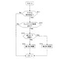
そのため、本実施形態では、図3に示すフローチャートの処理により、超リタード燃焼が行われているか否かに応じてアイドル回転速度制御の制御方法を切り換えている。なお、触媒昇温時におけるアイドル運転時で行われるアイドル回転速度制御を第2ISC制御と呼ぶ。
この図3は、上記のコントロールユニット25により所定期間毎(所定クランク角あるいは所定時間毎)に繰り返し実行される制御内容を示すフローチャートである。先ず、ステップS11では、アイドル回転速度制御の実行条件が成立するかが判定される。このアイドル回転速度制御の実行条件は、アイドルスイッチ信号がONで、かつ、アクセルペダルが略踏み込まれていないとき成立する。尚、アイドルスイッチは、電子制御スロットル弁7の開度が全閉付近でONとなるスイッチである。また、アイドル回転速度制御の実行条件を、例えば、車速が実質的に0(ゼロ)等の条件に基づいて成立させても良い。なお、このアイドルスイッチ信号は、必ずしも物理的なスイッチでなくともよく、例えばアクセル開度センサ23の検出信号から生成されても良い。
During normal idle operation other than when the catalyst temperature rises without performing super retard combustion, the engine speed detected and calculated by the
On the other hand, at the time of the above-mentioned super retard combustion, that is, at the time of idling operation when the temperature of the catalyst is raised, the exhaust gas temperature is controlled to be extremely higher than that at the time of normal idling operation. If the throttle opening is corrected to the open side and the intake air amount is increased when the rotational speed becomes smaller than the rotational speed, the exhaust temperature originally increased for the early temperature rise of the
Therefore, in the present embodiment, the control method of the idle rotation speed control is switched according to whether or not the super retard combustion is performed by the processing of the flowchart shown in FIG. Note that the idle rotation speed control performed during the idling operation when the temperature of the catalyst is raised is referred to as a second ISC control.
FIG. 3 is a flowchart showing the control contents repeatedly executed by the
ステップS12では、機関回転速度を目標アイドル回転速度に一致させるフィードバック制御条件が成立するか否かが判定される。このフィードバック条件には、フィードバック制御に用いられるセンサやアクチュエータ類が正常であるか、また目標アイドル回転速度と機関回転速度の偏差が所定の基準範囲内にあるか等が含まれる。 In step S12, it is determined whether or not a feedback control condition for causing the engine speed to coincide with the target idle speed is satisfied. This feedback condition includes whether the sensors and actuators used for feedback control are normal and whether the deviation between the target idle speed and the engine speed is within a predetermined reference range.
上記のアイドル条件及びフィードバック条件の双方が成立する場合、ステップS13へ進み、上述した超リタード燃焼が行われているかを判定する。超リタード燃焼を実行していない場合はステップS14へ進み、上述した第1ISC制御が行われる。
第1ISC制御については、図4を用いて説明する。図4は、エンジン始動からアイドル運転での点火時期やスロットル開度の制御状態を示すタイムチャートである。まず、スタータスイッチがONとなると(T0)、スタータによるクランキングが開始されてエンジンが完爆する(T2)。そして完爆後からに機関回転速度rNeがオーバーシュートしている期間(T2〜T3)では、機関回転速度rNeを目標アイドル回転速度INeへ向けて低下させるために、スロットル開度を徐々に小さくする。そして、機関回転速度rNeが目標アイドル回転速度tINe付近まで低下すると(T3)、機関回転速度rNeが目標アイドル回転速度tINeに一致するようにスロットル開度と点火時期とをフィードバック制御する。このフィードバック制御は周知のように例えばPI制御を用いて行われる。尚、燃料噴射量の制御はスロットル開度が開き側に制御された場合は、吸入空気量の増加に応じて増量されるようになっている。
そして、エンジン始動から所定期間を経過した時点T4で、オルタネータ等の補機負荷が加わると、機関回転速度rNeが低下する。すると、低下した機関回転速度rNEを目標アイドル回転速度tINeへフィードバックするために、スロットル開度を開き側に制御することにより吸入空気量を増加するのとともに、点火時期が一時的に進角することでトルクを上昇させる。このように、超リタード燃焼が実行されていないときに実行する第1ISC制御では、点火時期とスロットル開度、燃料噴射量を制御して目標アイドル回転速度へのフィードバック制御を行っている。
ここで、図2のフローチャートの説明に戻る。ステップS13において、例えば冷機始動時のように触媒コンバータ10を速やかに活性化すべき状態、つまり超リタード燃焼が実行される場合には、ステップS15へ進み、第1ISC制御とは異なる第2ISC制御が行われる。
If both the idle condition and the feedback condition are satisfied, the process proceeds to step S13 to determine whether the above-described super retard combustion is performed. When the super retard combustion is not executed, the process proceeds to step S14, and the first ISC control described above is performed.
The first ISC control will be described with reference to FIG. FIG. 4 is a time chart showing a control state of the ignition timing and the throttle opening from the engine start to the idle operation. First, when the starter switch is turned on (T0), cranking by the starter is started and the engine is completely exploded (T2). In the period (T2 to T3) in which the engine speed rNe is overshooting after the complete explosion, the throttle opening is gradually decreased in order to decrease the engine speed rNe toward the target idle speed INe. . When the engine speed rNe decreases to near the target idle speed tINe (T3), the throttle opening and the ignition timing are feedback-controlled so that the engine speed rNe matches the target idle speed tINe. As is well known, this feedback control is performed using, for example, PI control. The control of the fuel injection amount is increased according to the increase of the intake air amount when the throttle opening is controlled to the open side.
Then, when an auxiliary machine load such as an alternator is applied at a time T4 when a predetermined period has elapsed from the start of the engine, the engine speed rNe decreases. Then, in order to feed back the reduced engine speed rNE to the target idle speed tINe, the intake air amount is increased by controlling the throttle opening to the open side, and the ignition timing is temporarily advanced. Increase the torque with. Thus, in the first ISC control executed when the super retard combustion is not executed, feedback control to the target idle speed is performed by controlling the ignition timing, the throttle opening, and the fuel injection amount.
Here, the description returns to the flowchart of FIG. In step S13, for example, when the
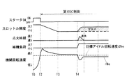
ここで、第2ISC制御について、図5のタイムチャートを用いて説明する。スタータスイッチがONとなると(T0)、スタータによるクランキングが開始されるとともに、圧縮行程1度噴射の成層燃焼による初爆が行われ、タイミングT1で、成層燃焼から超リタード燃焼へ切り換えられる。そして、この超リタード燃焼が実行されている場合は、第2ISC制御が行われる。
本実施形態における第2ISC制御では、図5に示す期間T2〜T3のように、スロットル開度は、クランキング時に設定されている開度から、超リタード燃焼中に機関回転速度rNeを目標アイドル回転速度tINeに維持する開度に向けて徐々に低下する。この間、スロットル開度の低下に伴って吸入空気量が低減される。機関回転速度rNeが目標アイドル回転速度rINe付近まで低下した時点T3以降のスロットル開度は、超リタード燃焼時のマップにより設定される。この時のスロットル開度は、超リタード燃焼によるトルク低下を補償する開度であり、第1ISC制御で設定されるスロットル開度に比べて大きい開度に設定されている。但し、触媒昇温時におけるアイドル運転時では、主として点火時期を調整することで、機関回転速度を目標アイドル回転速度へ向けてフィードバック制御しており、例えば補機負荷が付与された後(T4〜)のように、機関回転速度rNeが目標アイドル回転速度tINeより低下した場合には、補記負荷の入力による機関回転速度の低下を補償するためにスロットル開度を開き側に制御することを禁止している。
前述の通り、超リタード燃焼時のスロットル開度は、機関回転速度と負荷のマップにより設定されており、燃料噴射時期と点火時期を燃焼安定性が許容されるリタード限界に設定した際に機関回転速度rNeを目標アイドル回転速度tINeに維持できる開度である。
このように設定されるスロットル開度に対し、第2ISC制御は、補機負荷の入力に伴い機関回転速度rNeが低下しても、第1ISC制御のように開き側に補正することを禁止する。そして、超リタード燃焼での設定点火時期を進角させることにより補機負荷により落ち込んだ機関回転速度rNeを目標アイドル回転速度tINeに復帰させる。
超リタード燃焼は点火プラグ周りに濃い燃料混合気を集めるために点火時期の直前に燃料噴射を行っているため、点火時期の進角に応じて燃料噴射時期を進角させる。具体的には、燃料噴射時期と点火時期との間を略一定の期間αを確保するように、点火時期の進角(あるいは遅角)と同期して燃料噴射時期を進角(あるいは遅角)させる。
Here, the second ISC control will be described with reference to the time chart of FIG. When the starter switch is turned on (T0), cranking by the starter is started, and an initial explosion is performed by stratified combustion with a single compression stroke injection. At timing T1, stratified combustion is switched to super retarded combustion. And when this super retard combustion is performed, 2nd ISC control is performed.
In the second ISC control in the present embodiment, the throttle opening is set to the target idle speed from the opening set at the time of cranking to the engine speed rNe during the super retard combustion, as in the periods T2 to T3 shown in FIG. It gradually decreases toward the opening degree that maintains the speed tINe. During this time, the intake air amount is reduced as the throttle opening decreases. The throttle opening after time T3 when the engine rotational speed rNe decreases to near the target idle rotational speed rINe is set by a map at the time of super retard combustion. The throttle opening at this time is an opening that compensates for torque reduction due to super retard combustion, and is set to a larger opening than the throttle opening set in the first ISC control. However, during idle operation when the catalyst temperature rises, feedback control is performed so that the engine speed is adjusted toward the target idle speed mainly by adjusting the ignition timing. For example, after an auxiliary machine load is applied (T4- ), When the engine speed rNe is lower than the target idle speed tINe, it is prohibited to control the throttle opening to the open side in order to compensate for the decrease in the engine speed due to the input of the additional load. ing.
As described above, the throttle opening at the time of super retard combustion is set by the engine speed and load map, and the engine speed is set when the fuel injection timing and ignition timing are set to the retard limit where the combustion stability is allowed. This is the opening degree at which the speed rNe can be maintained at the target idle rotation speed tINe.
With respect to the throttle opening set in this way, the second ISC control prohibits correction to the open side as in the first ISC control even if the engine speed rNe decreases with the input of the auxiliary machine load. Then, by advancing the set ignition timing in the super retard combustion, the engine speed rNe that has fallen due to the auxiliary load is returned to the target idle speed tINe.
In super retard combustion, since fuel injection is performed immediately before the ignition timing in order to collect a rich fuel mixture around the spark plug, the fuel injection timing is advanced according to the advance of the ignition timing. Specifically, the fuel injection timing is advanced (or retarded) in synchronization with the advance (or retard) of the ignition timing so as to ensure a substantially constant period α between the fuel injection timing and the ignition timing. )
図6は、図5と同様、超リタード燃焼時に第2ISC制御が行われる状態であって、かつ、図5の状況よりも補機負荷が大きい場合である。この場合、補機負荷による機関回転速度rNeの低下が大きく、これを補うための点火時期の進角量が大きくなる。そして、点火時期が予め設定された値であって、安定した超リタード燃焼を確保できる進角側の限界値に達した時点T5で、超リタード燃焼が中止・解除される。そして、超リタード燃焼から吸気行程に燃料を噴射する均質燃焼に切り換えられるとともに、第2ISC制御から上記の第1ISC制御へ切り換えられる。 FIG. 6 shows a state where the second ISC control is performed at the time of super retard combustion, as in FIG. 5, and the auxiliary load is larger than the situation of FIG. 5. In this case, the decrease in the engine speed rNe due to the load on the auxiliary machine is large, and the advance amount of the ignition timing for making up for this increases. Then, the super retard combustion is stopped / released at a time T5 when the ignition timing is a preset value and reaches a limit value on the advance side where stable super retard combustion can be secured. Then, the super-retard combustion is switched to the homogeneous combustion in which fuel is injected in the intake stroke, and the second ISC control is switched to the first ISC control.
以上のように本実施形態によれば、触媒コンバータ10の早期昇温が要求される内燃機関の冷間始動時には、超リタード燃焼を行うので、触媒の早期活性化と後燃えによるHC低減を実現することができる。また、超リタード燃焼を行わない場合には、機関回転速度rNeが目標アイドル回転速度tINeと一致するように、スロットル開度と点火時期をフィードバック制御する第1ISC制御を行うことによって、機関回転速度rNeを目標アイドル回転速度tINeに精度良く維持することができる。
As described above, according to the present embodiment, super-retard combustion is performed at the time of cold start of an internal combustion engine that requires an early temperature increase of the
一方、超リタード燃焼が実行されている場合には、触媒コンバータ10の早期昇温のために排気温度を高くしている。このときの燃料噴射時期・点火時期のリタード量は、燃焼安定性が許容される限界リタード量に設定されている。尚、燃焼安定性および/または触媒コンバータ10の熱劣化による寿命等を考慮してリタード量を設定しても良い。
このような超リタード燃焼の実行中に、補機負荷の付与等に起因して機関回転速度rNeが低下した場合に、吸入空気量を増加させると、これに伴って燃料噴射量が増加し、その燃焼による熱量が増大してしまう。前述したとおり、超リタード燃焼時は触媒コンバータ10にとって熱的に厳しい環境なので、補機負荷に起因して燃焼による熱量が高くなってしまうと、熱的損傷ないし劣化を生じる懸念がある。
そこで本実施形態では、超リタード燃焼を行う場合は、第1ISC制御に変えて第2ISC制御を行っているのである。第2ISC制御では、機関回転速度が目標アイドル回転速度よりも低い場合に、点火時期の進角と、これに伴う燃料噴射時期の進角によってトルクを上昇させるので、吸入空気量を増加させる第1ISC制御に比して、燃焼による熱量の増加を抑制してトルクを増加させることができるので、触媒コンバータ10を過度に昇温することを抑制できる。
尚、超リタード燃焼では、点火時期が既にMBT(minimum advance for best torque:最適点火時期)点に対して大幅に遅角しているために、通常燃焼に比して、点火時期の進角化によるトルク向上効果が高い。このため、スロットル開度を制御せずとも、点火時期の進角によって機関回転速度の落ち込みを速やかに目標アイドル回転速度に復帰させることができる。
尚、超リタード燃焼では、点火時期が既に大幅に遅角されているために、点火時期の更なる遅角化が困難であり、また、点火時期の遅角化によるトルク感度が低い。そこで第2ISC制御では、機関回転速度rNeを目標アイドル回転速度tINeへ向けて低下させる時には、第1ISC制御と同様にスロットル開度により吸入空気量を低下させる。一方、機関回転速度rNeを目標アイドル回転速度tINeへ向けて上昇させる時には、吸入空気量を増大することなく、点火時期を進角させると共に燃料噴射時期を進角させる。つまり、第2ISC制御では、機関回転速度が目標アイドル回転速度よりも高い場合には、機関回転速度と目標アイドル回転速度との偏差に応じてスロットル開度を低下側・閉じ側に調整し、機関回転速度が目標アイドル回転速度よりも低い場合には、スロットル開度の増加を禁止し、機関回転速度と目標アイドル回転速度との偏差に応じて点火時期を進角側に調整するようになっている。これによって、超リタード燃焼時であっても、触媒コンバータ10への熱的な影響を抑制して、目標アイドル回転速度tINeへの制御を応答性良く行うことができる。
On the other hand, when the super retard combustion is being performed, the exhaust gas temperature is raised to raise the temperature of the
When the engine rotation speed rNe is reduced due to the application of an auxiliary machine load or the like during execution of such super retard combustion, if the intake air amount is increased, the fuel injection amount is increased accordingly. The amount of heat due to the combustion increases. As described above, the super retard combustion is a thermally harsh environment for the
Therefore, in the present embodiment, when super retard combustion is performed, the second ISC control is performed instead of the first ISC control. In the second ISC control, when the engine rotational speed is lower than the target idle rotational speed, the torque is increased by the advance angle of the ignition timing and the advance angle of the fuel injection timing accompanying this, so the first ISC that increases the intake air amount Compared to control, it is possible to suppress an increase in the amount of heat due to combustion and increase the torque, so that it is possible to suppress excessive temperature rise of the
In super retarded combustion, the ignition timing is already substantially retarded from the MBT (minimum advance for best torque) point, so that the ignition timing is advanced compared to normal combustion. The torque improvement effect by is high. For this reason, it is possible to quickly return the engine speed drop to the target idle speed by the advance of the ignition timing without controlling the throttle opening.
In the super retard combustion, since the ignition timing is already largely retarded, it is difficult to further retard the ignition timing, and the torque sensitivity due to the retarded ignition timing is low. Therefore, in the second ISC control, when the engine speed rNe is decreased toward the target idle speed tINe, the intake air amount is decreased by the throttle opening as in the first ISC control. On the other hand, when the engine speed rNe is increased toward the target idle speed tINe, the ignition timing is advanced and the fuel injection timing is advanced without increasing the intake air amount. That is, in the second ISC control, when the engine speed is higher than the target idle speed, the throttle opening is adjusted to the lower side or the closed side according to the deviation between the engine speed and the target idle speed, and the engine When the rotational speed is lower than the target idle rotational speed, the throttle opening is prohibited from increasing, and the ignition timing is adjusted to the advance side according to the deviation between the engine rotational speed and the target idle rotational speed. Yes. Thereby, even during the super retard combustion, the thermal influence on the
以上のように本発明を具体的な実施形態に基づいて説明してきたが、本発明は上記実施形態に限定されるものではなく、その趣旨を逸脱しない範囲で、種々の変形・変更を含むものである。
例えば、上記第2ISC制御においては、機関回転速度rNeの上昇・低下にかかわらず、点火時期と燃料噴射時期のみを制御するようにしても良い。また、エンジンとモータを併用するハイブリッド車両等においては、超リタード燃焼時のトルクの低下を、モータによるトルクにて補償しも良い。
As described above, the present invention has been described based on specific embodiments. However, the present invention is not limited to the above embodiments, and includes various modifications and changes without departing from the spirit of the present invention. .
For example, in the second ISC control, only the ignition timing and the fuel injection timing may be controlled regardless of the increase / decrease in the engine speed rNe. Further, in a hybrid vehicle or the like that uses both an engine and a motor, a decrease in torque at the time of super retard combustion may be compensated by torque from the motor.
1…内燃機関
3…燃焼室
10…触媒コンバータ
13…排気温度センサ
14…点火プラグ
15…燃料噴射弁
25…コントロールユニット
DESCRIPTION OF
Claims (6)
前記触媒の昇温が要求される触媒昇温時に、点火時期を圧縮上死点後に設定して排気温度を上昇させる触媒昇温手段と、
前記触媒昇温時以外のアイドル運転時に、前記スロットル弁のスロットル開度を調整して、機関回転速度を目標アイドル回転速度にフィードバック制御する第1のアイドル回転速度制御手段と、
前記触媒昇温時におけるアイドル運転時に、前記スロットル弁の開き側の調整を禁止して、機関回転速度を目標アイドル回転速度にフィードバック制御する第2のアイドル回転速度制御手段と、
を備え、
前記第2のアイドル回転速度制御手段は、機関回転速度が目標アイドル回転速度よりも高い場合には、機関回転速度と目標アイドル回転速度との偏差に応じてスロットル開度を調整し、機関回転速度が目標アイドル回転速度よりも低い場合には、機関回転速度と目標アイドル回転速度との偏差に応じて点火時期を調整することを特徴とする筒内直接噴射式火花点火内燃機関の制御装置。 A cylinder provided with a throttle valve provided in the intake passage for adjusting the amount of intake air into the combustion chamber, a fuel injection valve for directly injecting fuel into the cylinder, a spark plug, and a catalyst provided in the exhaust passage In a control device for a direct injection spark ignition internal combustion engine,
Catalyst temperature raising means for setting the ignition timing after the compression top dead center and raising the exhaust gas temperature when raising the temperature of the catalyst required to raise the temperature of the catalyst;
First idle rotation speed control means for adjusting the throttle opening of the throttle valve and performing feedback control of the engine rotation speed to a target idle rotation speed during idle operation other than when the catalyst is heated;
During idle operation when the catalyst Atsushi Nobori, and prohibits the opening of the side adjustment of the throttle valve, and a second idle speed control means for feedback controlling the engine speed to the target idle rotational speed,
Equipped with a,
The second idle speed control means adjusts the throttle opening in accordance with the deviation between the engine speed and the target idle speed when the engine speed is higher than the target idle speed, and the engine speed A control device for a direct injection spark ignition internal combustion engine, wherein the ignition timing is adjusted in accordance with the deviation between the engine speed and the target idle speed when the engine speed is lower than the target idle speed .
前記第2のアイドル回転速度制御手段は、前記点火時期の進角に応じて燃料噴射時期を進角させることを特徴とする請求項1に記載の筒内直接噴射式火花点火内燃機関の制御装置。 The catalyst temperature raising means sets the fuel injection timing after compression top dead center,
2. The control device for a direct injection spark-ignition internal combustion engine according to claim 1, wherein the second idle speed control means advances the fuel injection timing in accordance with the advance angle of the ignition timing. .
触媒の昇温が要求される触媒昇温時には、点火時期を圧縮上死点後に設定して排気温度を上昇させ、
前記触媒昇温時以外でのアイドル運転中には、機関回転速度が目標アイドル回転速度に一致するようにスロットル開度を調整する一方、
前記触媒昇温時でのアイドル運転中には、前記スロットル弁の開き側の調整を禁止するとともに、機関回転速度が目標アイドル回転速度に一致するように、機関回転速度が目標アイドル回転速度よりも高い場合には、機関回転速度と目標アイドル回転速度との偏差に応じてスロットル開度を調整し、機関回転速度が目標アイドル回転速度よりも低い場合には、機関回転速度と目標アイドル回転速度との偏差に応じて点火時期を調整することを特徴とする筒内直接噴射式火花点火内燃機関の制御方法。 A cylinder provided with a throttle valve provided in the intake passage for adjusting the amount of intake air into the combustion chamber, a fuel injection valve for directly injecting fuel into the cylinder, a spark plug, and a catalyst provided in the exhaust passage In a control method for a direct injection spark ignition internal combustion engine,
When the temperature of the catalyst is required to rise, the ignition timing is set after compression top dead center to raise the exhaust temperature,
During idle operation other than during the catalyst temperature rise, while adjusting the throttle opening so that the engine speed matches the target idle speed,
During idle operation at the time of catalyst temperature rise , adjustment on the opening side of the throttle valve is prohibited , and the engine speed is higher than the target idle speed so that the engine speed matches the target idle speed. When the engine speed is high, the throttle opening is adjusted according to the deviation between the engine speed and the target idle speed, and when the engine speed is lower than the target idle speed, the engine speed and the target idle speed A control method for an in-cylinder direct injection spark ignition internal combustion engine, characterized in that the ignition timing is adjusted in accordance with the deviation of .
Priority Applications (1)
| Application Number | Priority Date | Filing Date | Title |
|---|---|---|---|
| JP2007167204A JP4893499B2 (en) | 2006-06-26 | 2007-06-26 | In-cylinder direct injection spark ignition internal combustion engine control device and control method |
Applications Claiming Priority (3)
| Application Number | Priority Date | Filing Date | Title |
|---|---|---|---|
| JP2006174789 | 2006-06-26 | ||
| JP2006174789 | 2006-06-26 | ||
| JP2007167204A JP4893499B2 (en) | 2006-06-26 | 2007-06-26 | In-cylinder direct injection spark ignition internal combustion engine control device and control method |
Publications (3)
| Publication Number | Publication Date |
|---|---|
| JP2008031991A JP2008031991A (en) | 2008-02-14 |
| JP2008031991A5 JP2008031991A5 (en) | 2010-08-12 |
| JP4893499B2 true JP4893499B2 (en) | 2012-03-07 |
Family
ID=39121676
Family Applications (1)
| Application Number | Title | Priority Date | Filing Date |
|---|---|---|---|
| JP2007167204A Expired - Fee Related JP4893499B2 (en) | 2006-06-26 | 2007-06-26 | In-cylinder direct injection spark ignition internal combustion engine control device and control method |
Country Status (1)
| Country | Link |
|---|---|
| JP (1) | JP4893499B2 (en) |
Families Citing this family (7)
| Publication number | Priority date | Publication date | Assignee | Title |
|---|---|---|---|---|
| JP5041374B2 (en) * | 2009-01-28 | 2012-10-03 | トヨタ自動車株式会社 | Start control device for internal combustion engine |
| JP5900365B2 (en) * | 2013-01-28 | 2016-04-06 | トヨタ自動車株式会社 | Control device for internal combustion engine |
| JP6274814B2 (en) * | 2013-10-28 | 2018-02-07 | ダイハツ工業株式会社 | Control device for internal combustion engine |
| KR101517794B1 (en) * | 2013-10-31 | 2015-05-06 | 한국기계연구원 | Method for purifying exhaustgas of gasoline engine |
| JP6377022B2 (en) * | 2015-06-08 | 2018-08-22 | 日立オートモティブシステムズ株式会社 | Control device for internal combustion engine |
| JP7424196B2 (en) | 2020-05-01 | 2024-01-30 | トヨタ自動車株式会社 | engine equipment |
| JP7428066B2 (en) | 2020-05-01 | 2024-02-06 | トヨタ自動車株式会社 | engine equipment |
Family Cites Families (11)
| Publication number | Priority date | Publication date | Assignee | Title |
|---|---|---|---|---|
| JP3257420B2 (en) * | 1996-11-21 | 2002-02-18 | 三菱自動車工業株式会社 | In-cylinder injection internal combustion engine |
| JP3812156B2 (en) * | 1998-07-21 | 2006-08-23 | マツダ株式会社 | Control device for engine with mechanical supercharger |
| JP3478163B2 (en) * | 1999-04-06 | 2003-12-15 | トヨタ自動車株式会社 | Control device for internal combustion engine |
| JP3788130B2 (en) * | 1999-09-08 | 2006-06-21 | トヨタ自動車株式会社 | Control device for internal combustion engine |
| JP3799898B2 (en) * | 1999-09-20 | 2006-07-19 | 株式会社日立製作所 | In-cylinder injection engine control device |
| JP2002089339A (en) * | 2000-09-12 | 2002-03-27 | Toyota Motor Corp | Cylinder fuel injection type spark ignition internal combustion engine |
| JP4410454B2 (en) * | 2002-04-03 | 2010-02-03 | 三菱自動車工業株式会社 | Idle speed control device for internal combustion engine |
| JP4269922B2 (en) * | 2003-12-10 | 2009-05-27 | トヨタ自動車株式会社 | Control device for internal combustion engine |
| JP2005214039A (en) * | 2004-01-28 | 2005-08-11 | Nissan Motor Co Ltd | Control device for direct spark ignition type internal combustion engine |
| JP4311231B2 (en) * | 2004-03-01 | 2009-08-12 | 日産自動車株式会社 | Engine idle speed control device |
| JP4389688B2 (en) * | 2004-06-16 | 2009-12-24 | トヨタ自動車株式会社 | Internal combustion engine fuel injection control device |
-
2007
- 2007-06-26 JP JP2007167204A patent/JP4893499B2/en not_active Expired - Fee Related
Also Published As
| Publication number | Publication date |
|---|---|
| JP2008031991A (en) | 2008-02-14 |
Similar Documents
| Publication | Publication Date | Title |
|---|---|---|
| US7051701B2 (en) | Direct fuel injection/spark ignition engine control device | |
| US7287500B2 (en) | Start controller for internal combustion engine | |
| EP1647690B1 (en) | Combustion control system and method for direct-injection spark-ignition internal combustion engine | |
| JP4023115B2 (en) | Control device for direct-injection spark ignition engine | |
| JPH11336574A (en) | Control device for internal combustion engine | |
| JP4893499B2 (en) | In-cylinder direct injection spark ignition internal combustion engine control device and control method | |
| JP6350972B2 (en) | Engine control device | |
| EP1873380B1 (en) | Control device and control method for spark-ignited internal-combustion engine | |
| JP3893909B2 (en) | Control device for direct-injection spark-ignition internal combustion engine | |
| JP4135643B2 (en) | Control device for direct-injection spark-ignition internal combustion engine | |
| JP4379286B2 (en) | In-cylinder direct injection spark ignition internal combustion engine controller | |
| JP4020072B2 (en) | Control device for internal combustion engine | |
| JP4000926B2 (en) | Control device and control method for direct-injection spark ignition engine | |
| JP4032859B2 (en) | Control device for direct-injection spark ignition engine | |
| JP4943873B2 (en) | In-cylinder injection spark ignition internal combustion engine control device | |
| JP4631725B2 (en) | In-cylinder direct injection spark ignition internal combustion engine controller | |
| JP2002130024A (en) | Controller for direct injection spark ignition type internal combustion engine | |
| JP2008274789A (en) | Control system for direct injection engine | |
| JP2006177179A (en) | Control device for cylinder direct injection type spark ignition internal combustion engine | |
| JP4529832B2 (en) | In-cylinder direct injection spark ignition internal combustion engine controller | |
| JP4333548B2 (en) | In-cylinder direct injection spark ignition internal combustion engine controller | |
| JP4281663B2 (en) | In-cylinder direct injection spark ignition internal combustion engine controller | |
| JP5195383B2 (en) | In-cylinder direct injection spark ignition internal combustion engine | |
| JP2010163930A (en) | Control device of direct-injection spark ignition internal combustion engine | |
| JP4899772B2 (en) | Control device for internal combustion engine |
Legal Events
| Date | Code | Title | Description |
|---|---|---|---|
| A521 | Request for written amendment filed |
Free format text: JAPANESE INTERMEDIATE CODE: A523 Effective date: 20100625 |
|
| A621 | Written request for application examination |
Free format text: JAPANESE INTERMEDIATE CODE: A621 Effective date: 20100625 |
|
| A977 | Report on retrieval |
Free format text: JAPANESE INTERMEDIATE CODE: A971007 Effective date: 20110825 |
|
| A131 | Notification of reasons for refusal |
Free format text: JAPANESE INTERMEDIATE CODE: A131 Effective date: 20110830 |
|
| A521 | Request for written amendment filed |
Free format text: JAPANESE INTERMEDIATE CODE: A523 Effective date: 20111027 |
|
| TRDD | Decision of grant or rejection written | ||
| A01 | Written decision to grant a patent or to grant a registration (utility model) |
Free format text: JAPANESE INTERMEDIATE CODE: A01 Effective date: 20111122 |
|
| A01 | Written decision to grant a patent or to grant a registration (utility model) |
Free format text: JAPANESE INTERMEDIATE CODE: A01 |
|
| A61 | First payment of annual fees (during grant procedure) |
Free format text: JAPANESE INTERMEDIATE CODE: A61 Effective date: 20111205 |
|
| R150 | Certificate of patent or registration of utility model |
Ref document number: 4893499 Country of ref document: JP Free format text: JAPANESE INTERMEDIATE CODE: R150 Free format text: JAPANESE INTERMEDIATE CODE: R150 |
|
| FPAY | Renewal fee payment (event date is renewal date of database) |
Free format text: PAYMENT UNTIL: 20150106 Year of fee payment: 3 |
|
| LAPS | Cancellation because of no payment of annual fees |