WO2014104337A1 - 清掃部材を製造する方法及び装置 - Google Patents
清掃部材を製造する方法及び装置 Download PDFInfo
- Publication number
- WO2014104337A1 WO2014104337A1 PCT/JP2013/085203 JP2013085203W WO2014104337A1 WO 2014104337 A1 WO2014104337 A1 WO 2014104337A1 JP 2013085203 W JP2013085203 W JP 2013085203W WO 2014104337 A1 WO2014104337 A1 WO 2014104337A1
- Authority
- WO
- WIPO (PCT)
- Prior art keywords
- fiber bundle
- sent
- drive roll
- fiber
- rotating bar
- Prior art date
- Legal status (The legal status is an assumption and is not a legal conclusion. Google has not performed a legal analysis and makes no representation as to the accuracy of the status listed.)
- Ceased
Links
Images



Classifications
-
- B—PERFORMING OPERATIONS; TRANSPORTING
- B08—CLEANING
- B08B—CLEANING IN GENERAL; PREVENTION OF FOULING IN GENERAL
- B08B1/00—Cleaning by methods involving the use of tools
- B08B1/10—Cleaning by methods involving the use of tools characterised by the type of cleaning tool
- B08B1/14—Wipes; Absorbent members, e.g. swabs or sponges
- B08B1/143—Wipes
-
- D—TEXTILES; PAPER
- D02—YARNS; MECHANICAL FINISHING OF YARNS OR ROPES; WARPING OR BEAMING
- D02J—FINISHING OR DRESSING OF FILAMENTS, YARNS, THREADS, CORDS, ROPES OR THE LIKE
- D02J1/00—Modifying the structure or properties resulting from a particular structure; Modifying, retaining, or restoring the physical form or cross-sectional shape, e.g. by use of dies or squeeze rollers
- D02J1/18—Separating or spreading
-
- A—HUMAN NECESSITIES
- A46—BRUSHWARE
- A46D—MANUFACTURE OF BRUSHES
- A46D1/00—Bristles; Selection of materials for bristles
- A46D1/04—Preparing bristles
-
- B—PERFORMING OPERATIONS; TRANSPORTING
- B32—LAYERED PRODUCTS
- B32B—LAYERED PRODUCTS, i.e. PRODUCTS BUILT-UP OF STRATA OF FLAT OR NON-FLAT, e.g. CELLULAR OR HONEYCOMB, FORM
- B32B5/00—Layered products characterised by the non- homogeneity or physical structure, i.e. comprising a fibrous, filamentary, particulate or foam layer; Layered products characterised by having a layer differing constitutionally or physically in different parts
- B32B5/02—Layered products characterised by the non- homogeneity or physical structure, i.e. comprising a fibrous, filamentary, particulate or foam layer; Layered products characterised by having a layer differing constitutionally or physically in different parts characterised by structural features of a fibrous or filamentary layer
- B32B5/022—Non-woven fabric
-
- B—PERFORMING OPERATIONS; TRANSPORTING
- B32—LAYERED PRODUCTS
- B32B—LAYERED PRODUCTS, i.e. PRODUCTS BUILT-UP OF STRATA OF FLAT OR NON-FLAT, e.g. CELLULAR OR HONEYCOMB, FORM
- B32B5/00—Layered products characterised by the non- homogeneity or physical structure, i.e. comprising a fibrous, filamentary, particulate or foam layer; Layered products characterised by having a layer differing constitutionally or physically in different parts
- B32B5/02—Layered products characterised by the non- homogeneity or physical structure, i.e. comprising a fibrous, filamentary, particulate or foam layer; Layered products characterised by having a layer differing constitutionally or physically in different parts characterised by structural features of a fibrous or filamentary layer
- B32B5/12—Layered products characterised by the non- homogeneity or physical structure, i.e. comprising a fibrous, filamentary, particulate or foam layer; Layered products characterised by having a layer differing constitutionally or physically in different parts characterised by structural features of a fibrous or filamentary layer characterised by the relative arrangement of fibres or filaments of different layers, e.g. the fibres or filaments being parallel or perpendicular to each other
-
- B—PERFORMING OPERATIONS; TRANSPORTING
- B32—LAYERED PRODUCTS
- B32B—LAYERED PRODUCTS, i.e. PRODUCTS BUILT-UP OF STRATA OF FLAT OR NON-FLAT, e.g. CELLULAR OR HONEYCOMB, FORM
- B32B5/00—Layered products characterised by the non- homogeneity or physical structure, i.e. comprising a fibrous, filamentary, particulate or foam layer; Layered products characterised by having a layer differing constitutionally or physically in different parts
- B32B5/22—Layered products characterised by the non- homogeneity or physical structure, i.e. comprising a fibrous, filamentary, particulate or foam layer; Layered products characterised by having a layer differing constitutionally or physically in different parts characterised by the presence of two or more layers which are next to each other and are fibrous, filamentary, formed of particles or foamed
- B32B5/24—Layered products characterised by the non- homogeneity or physical structure, i.e. comprising a fibrous, filamentary, particulate or foam layer; Layered products characterised by having a layer differing constitutionally or physically in different parts characterised by the presence of two or more layers which are next to each other and are fibrous, filamentary, formed of particles or foamed one layer being a fibrous or filamentary layer
- B32B5/26—Layered products characterised by the non- homogeneity or physical structure, i.e. comprising a fibrous, filamentary, particulate or foam layer; Layered products characterised by having a layer differing constitutionally or physically in different parts characterised by the presence of two or more layers which are next to each other and are fibrous, filamentary, formed of particles or foamed one layer being a fibrous or filamentary layer another layer next to it also being fibrous or filamentary
-
- D—TEXTILES; PAPER
- D01—NATURAL OR MAN-MADE THREADS OR FIBRES; SPINNING
- D01D—MECHANICAL METHODS OR APPARATUS IN THE MANUFACTURE OF ARTIFICIAL FILAMENTS, THREADS, FIBRES, BRISTLES OR RIBBONS
- D01D11/00—Other features of manufacture
- D01D11/02—Opening bundles to space the threads or filaments from one another
-
- B—PERFORMING OPERATIONS; TRANSPORTING
- B32—LAYERED PRODUCTS
- B32B—LAYERED PRODUCTS, i.e. PRODUCTS BUILT-UP OF STRATA OF FLAT OR NON-FLAT, e.g. CELLULAR OR HONEYCOMB, FORM
- B32B2250/00—Layers arrangement
- B32B2250/20—All layers being fibrous or filamentary
-
- B—PERFORMING OPERATIONS; TRANSPORTING
- B32—LAYERED PRODUCTS
- B32B—LAYERED PRODUCTS, i.e. PRODUCTS BUILT-UP OF STRATA OF FLAT OR NON-FLAT, e.g. CELLULAR OR HONEYCOMB, FORM
- B32B2262/00—Composition or structural features of fibres which form a fibrous or filamentary layer or are present as additives
- B32B2262/02—Synthetic macromolecular fibres
- B32B2262/0276—Polyester fibres
- B32B2262/0284—Polyethylene terephthalate [PET] or polybutylene terephthalate [PBT]
-
- B—PERFORMING OPERATIONS; TRANSPORTING
- B32—LAYERED PRODUCTS
- B32B—LAYERED PRODUCTS, i.e. PRODUCTS BUILT-UP OF STRATA OF FLAT OR NON-FLAT, e.g. CELLULAR OR HONEYCOMB, FORM
- B32B2262/00—Composition or structural features of fibres which form a fibrous or filamentary layer or are present as additives
- B32B2262/12—Conjugate fibres, e.g. core/sheath or side-by-side
-
- B—PERFORMING OPERATIONS; TRANSPORTING
- B32—LAYERED PRODUCTS
- B32B—LAYERED PRODUCTS, i.e. PRODUCTS BUILT-UP OF STRATA OF FLAT OR NON-FLAT, e.g. CELLULAR OR HONEYCOMB, FORM
- B32B2432/00—Cleaning articles, e.g. mops or wipes
Definitions
- the present invention relates to a method and an apparatus for manufacturing a cleaning member having an opened fiber bundle.
- the opened fiber bundle is used.
- a method for opening a fiber bundle a method is known in which a fiber bundle is drawn from a storage container by a drive roll and sent to a fiber opening process (for example, Patent Document 1).
- the present invention provides a manufacturing method and a manufacturing apparatus for a cleaning member including an opened fiber bundle, in which the twist of the fiber bundle is corrected and manufactured in a path for transporting the fiber bundle from the storage container to the drive roll.
- An object of the present invention is to provide a manufacturing method and a manufacturing apparatus capable of stabilizing a process and pre-opening a fiber bundle in a path for conveying a fiber bundle from a driving roll to a fiber opening process, thereby speeding up the fiber opening process .
- the present invention includes the following steps: (A) The fiber bundle continuously drawn in the first direction from the storage container is wound around a first non-rotating bar provided in a direction intersecting the first direction, and the first direction Sending to a first drive roll after sending in a different second direction; (B) The fiber bundle fed in the third direction from the first drive roll is wound around a second non-rotating bar provided in a direction intersecting the third direction, and the third direction Includes a step of sending the second bundle to a second drive roll after sending in a different fourth direction, and (c) a step of opening the fiber bundle sent out from the second drive roll.
- a method for manufacturing a cleaning member is provided.
- the present invention also includes a first drive roll, a second drive roll, a first fiber bundle feed unit that sends a fiber bundle continuously drawn from a storage container to the first drive roll, A second fiber bundle feeding unit that sends the fiber bundle sent from the first drive roll to the second drive roll, and a fiber bundle opening unit that opens the fiber bundle sent from the second drive roll
- a cleaning member manufacturing apparatus including an opened fiber bundle, wherein the first fiber bundle feeding unit is continuously drawn from the storage container in a first direction. Is wound around a first non-rotating bar provided in a direction intersecting with the first direction, sent to a second direction different from the first direction, and then sent to the first drive roll
- the second fiber bundle feed unit feeds the first drive roll in the third direction.
- the fiber bundle is wound around a second non-rotating bar provided in a direction crossing the third direction and sent in a fourth direction different from the third direction, and then the second direction
- the manufacturing apparatus is provided to send to a driving roll.
- “send in the second direction and then send to the first driving roll” is added to the case where the fiber bundle sent in the second direction is sent as it is to the first driving roll.
- the case where the fiber bundle sent in the second direction is wound around one or a plurality of non-rotating bars to change the feeding direction and then sent to the first drive roll is included.
- “send to the second drive roll after sending in the fourth direction” in addition to sending the fiber bundle sent in the fourth direction as it is to the second drive roll, The case where the fiber bundle sent in the direction is wound around one or a plurality of non-rotating bars to change the feeding direction and then sent to the second drive roll is included.
- a manufacturing method and a manufacturing apparatus capable of stabilizing the process and preliminarily opening the fiber bundle in the path for conveying the fiber bundle from the driving roll to the opening process, and speeding up the opening process.
- FIG. 1 is a perspective view of a cleaning member manufactured by an embodiment of the method and apparatus of the present invention and a gripping tool fixed to the cleaning member.
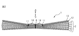
- 2 is a cross-sectional view taken along line XX of FIG.
- FIG. 3 is a plan view of the cleaning member shown in FIG. 1.
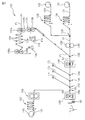
- FIG. 4 is a diagram for explaining a process of conveying the fiber bundle from the storage container to the drive roll and a process of conveying the fiber bundle from the drive roll to the fiber opening process among the manufacturing processes of the cleaning member shown in FIG.
- FIG. 5 is a schematic view for explaining the steps after the fiber opening step in the manufacturing process of the cleaning member shown in FIG. 1.
- the method according to one embodiment (Aspect 1A) of the present invention includes the following steps: (A) The fiber bundle continuously drawn in the first direction from the storage container is wound around a first non-rotating bar provided in a direction intersecting the first direction, and the first direction Sending to a first drive roll after sending in a different second direction; (B) The fiber bundle fed in the third direction from the first drive roll is wound around a second non-rotating bar provided in a direction intersecting the third direction, and the third direction Includes a step of sending the second bundle to a second drive roll after sending in a different fourth direction, and (c) a step of opening the fiber bundle sent out from the second drive roll. It is a manufacturing method of the cleaning member which comprises.
- the twist of the fiber bundle can be corrected in the path for conveying the fiber bundle from the storage container to the first drive roll, the manufacturing process can be stabilized, and the second drive from the first drive roll to the second drive roll.
- the fiber bundle is pre-opened in the path for conveying the fiber bundle to the drive roll and the subsequent fiber opening process, so that the speed of the fiber opening process can be increased.
- the tension of the fiber bundle sent in the second direction is larger than the tension of the fiber bundle sent in the first direction
- the third The tension of the fiber bundle sent in the fourth direction is larger than the tension of the fiber bundle sent in the direction.
- the first direction is upward in the direction of gravity.
- the twist of the fiber bundle drawn from the storage container can be corrected by the weight of the fiber bundle.
- the fiber bundle in the storage container is pulled out from the storage container by 3 to 5 m, the fiber bundle is wound around the first non-rotating bar. It is done.
- the twist of the fiber bundle drawn from the storage container is corrected by the own weight of the fiber bundle while preventing a decrease in strength due to the opening of the fiber bundle and a decrease in transportability associated therewith. Can do.
- the method according to any one of Embodiments 1A to 4A can include other steps in addition to steps (a) to (c). Other steps can be appropriately determined according to the configuration of the cleaning member to be manufactured. As other processes, for example, a process of attaching an oil agent to a fiber bundle, a process of forming a multilayer web by overlapping the fiber bundle with one or more other members (for example, a strip-shaped nonwoven fabric, etc.), a multilayer web A step of fixing the fiber bundle and other members contained in (for example, heat sealing, ultrasonic sealing, etc.), a step of cutting out individual cleaning members from the multilayer web, and the like. Such a method can include one or more of these steps.
- the order of performing each step is not particularly limited as long as there is no problem in the production of the cleaning member, and different steps may be performed at different times or simultaneously.
- the step can be performed during or after the opening step (c).
- the apparatus which concerns on 1 aspect (aspect 1B) of this invention is the 1st drive roll, the 2nd drive roll, and the 1st which sends the fiber bundle continuously pulled out from the storage container to the said 1st drive roll.
- a fiber bundle feed unit, a second fiber bundle feed unit that sends the fiber bundle sent from the first drive roll to the second drive roll, and a fiber bundle sent from the second drive roll An apparatus for manufacturing a cleaning member having a fiber bundle that has been opened, including a fiber bundle opening part that opens the fiber bundle, wherein the first fiber bundle feeding part is in the first direction from the storage container.
- the second fiber bundle feed section is fed to the first drive roll, and the first drive roll
- the fiber bundle sent out in the third direction is wound around a second non-rotating bar provided in a direction crossing the third direction and sent in a fourth direction different from the third direction. After that, it is the manufacturing apparatus which is sent to the second drive roll.
- the apparatus which concerns on aspect 1B, in the path
- the fiber bundle is pre-opened in the path for conveying the fiber bundle to the drive roll and the subsequent fiber opening process, so that the speed of the fiber opening process can be increased.
- the first fiber bundle feeding unit is configured to supply a fiber bundle that is sent in the first direction to a fiber bundle that is sent in the second direction. A tension larger than the tension is applied, and the second fiber bundle feeding unit applies a tension larger than the tension of the fiber bundle sent in the third direction to the fiber bundle sent in the fourth direction.
- the twist correction effect and preliminary opening effect of a fiber bundle can be improved.
- the first direction is upward in the direction of gravity.
- the twist of the fiber bundle pulled out from the storage container can be corrected with the dead weight of a fiber bundle.
- the first fiber bundle feeding unit is configured to extract the fiber bundle in the storage container from 3 to 5 m from the storage container. Wrap around the first non-rotating bar. According to the apparatus which concerns on aspect 4B, correcting the twist of the fiber bundle pulled out from the storage container by the own weight of a fiber bundle, preventing the fall of the intensity
- the apparatus according to any one of aspects 1B to 4B can include other configurations.
- Other configurations can be appropriately determined according to the configuration of the cleaning member to be manufactured.
- Other configurations include, for example, an oil agent application portion that applies an oil agent to a fiber bundle, a formation portion that forms a multilayer web by overlapping the fiber bundle with one or more other members (for example, a strip-shaped nonwoven fabric, etc.), Examples include a fixing part (for example, a heat seal part, an ultrasonic seal part, etc.) for fixing the fiber bundle and other members included in the multilayer web, and a cutting part for cutting out individual cleaning members from the multilayer web.
- the devices according to aspects 1B to 4B can include one or more of these configurations.
- the cleaning member manufactured by the method and apparatus of the present invention is not particularly limited as long as it has an opened fiber bundle.
- Examples of the cleaning member manufactured by the method and apparatus of the present invention include the cleaning member 1 shown in FIGS.
- FIGS an embodiment of the method and apparatus of the present invention will be described by taking the case of manufacturing the cleaning member 1 as an example.
- FIG. 1 is a perspective view of the cleaning member 1 and a gripping tool 15 fixed to the cleaning member 1
- FIG. 2 is a sectional view taken along line XX of FIG. 1
- FIG. 3 is a cleaning shown in FIG. 3 is a plan view of the member 1.
- FIG. 1 “upper” in FIG. 2 may be referred to as the upper side, and “lower” may be referred to as the lower side. However, “upper” and “lower” in FIG. Yes, and does not limit the vertical direction of the cleaning member 1.
- the cleaning member 1 includes a raised portion 2, a base sheet 12 stacked above the raised portion 2, and a holding sheet 13 stacked above the base sheet 12. It has.
- the cleaning member 1 is formed with an insertion portion 14 for inserting the insertion portion 16 of the gripping tool 15 between the base sheet 12 and the holding sheet 13. .
- the cleaning member 1 is formed with two inserted portions 14 so that the inserting portion 16 branched into two can be inserted.
- the number of inserted portions 14 in this embodiment is two, the number of inserted portions 14 can be changed as appropriate according to the number of branches of the inserting portion 16.
- Another embodiment includes an embodiment in which the number of inserted portions 14 is three or more.
- the raised portion 2 includes a first fibrous member 3, a second fibrous member 4 stacked on the lower side of the first fibrous member 3, and a lower portion of the second fibrous member 4.
- a four-layered fibrous member composed of a third fibrous member 5 stacked on the side and a fourth fibrous member 6 stacked on the lower side of the third fibrous member 5, and a fiber of this four-layered structure And a strip sheet 7 stacked on the lower side of the cylindrical member (the lower side of the fourth fibrous member 6).
- the fibrous member of the raised portion 2 in the present embodiment has a four-layer structure, the layer structure of the fibrous member can be changed as appropriate.
- Another embodiment includes an embodiment in which the layer structure of the fibrous member is a one-layer structure, a two-layer structure, or a three-layer structure, and as another embodiment, the layer structure of the fibrous member has five or more layers. Embodiments that are structures are mentioned. Moreover, although the raising part 2 in this embodiment is provided with the strip sheet 7, the presence or absence of the strip sheet 7 can be selected suitably. As another embodiment, an embodiment in which the strip sheet 7 is omitted can be cited.
- the first to fourth fibrous members 3 to 6 are fiber bundles to which an oil agent is attached.
- the oil agent in the present embodiment is a dust oil agent (for example, an oil agent mainly composed of liquid paraffin) that has an effect of promoting adsorption of dust, dust and the like.
- the amount of the oil per cleaning member is usually 0.05 to 2 g / piece, preferably 0.1 to 1 g / piece, and more preferably 0.2 to 0.5 g / piece. If the amount of oil is less than 0.05 g / piece, the retention of dust, dust, etc. may be reduced, and if it exceeds 2 g / piece, the oil will adhere to the cleaning place (for example, furniture) during cleaning. There is a fear.
- the component of the dusting oil agent is not particularly limited, and examples thereof include mineral oil, synthetic oil, silicone oil, and surfactant.
- mineral oils include paraffinic hydrocarbons, naphthenic hydrocarbons, and aromatic hydrocarbons.
- synthetic oils include alkylbenzene oils, polyolefin oils, polyglycol oils, and the like. Examples include linear dimethylpolysiloxane, cyclic dimethylpolysiloxane, methylhydropolyenepolysiloxane, various modified silicones, and the like, and examples of the surfactant include cationic surface activity such as quaternary ammonium salt type. And nonionic surfactants such as a polyethylene glycol type and a polyhydric alcohol type.
- the viscosity of the oil is preferably 108 to 128 mm 2 / S.
- This viscosity is an Ubbelohde viscometer (as defined in JIS K2839-1980, coefficient determined according to SIS B-0017), thermometer (for kinematic viscosity as defined in JIS B7410-1982) and constant temperature. Viscosity measured by the Ubbelohde method (30 ° C.) performed using a tank (as defined in JIS K2283-1983).
- the fiber bundle is, for example, tow (TOW), preferably opened tow.
- TOW tow
- Tow means a bundle of extremely large numbers of filaments as described in JIS L 0204-3: 1998 3.1.24.
- the fiber bundle may be a bundle of slit fibers (fibers formed by cutting and stretching a thin film), split fibers (fibers formed by dividing an elongated film into a network structure), and the like.
- fiber bundles include fiber bundles made of thermoplastic fibers, fiber bundles containing thermoplastic fibers, and the like.
- the raw material of the fiber constituting the fiber bundle include polyethylene, polypropylene, polyethylene terephthalate, nylon, and rayon.
- the fiber constituting the fiber bundle include, for example, a single fiber and a composite fiber (for example, Core-sheath type composite fiber, side-by-side type composite fiber) and the like.
- the composite fiber is preferably a core-sheath type composite fiber from the viewpoint of heat-fusibility, and more preferably a core-sheath type composite fiber having a melting point of the core higher than that of the sheath.
- Preferable core-sheath type composite fibers include, for example, core-sheath type composite fibers in which the core is made of polypropylene or polyethylene terephthalate and the sheath is made of polyethylene. Further preferable core-sheath type composite fibers include, for example, polyethylene in the core. A core-sheath type composite fiber made of terephthalate and having a sheath made of polyethylene can be mentioned.
- the fineness of the fibers constituting the fiber bundle is preferably 1 to 50 dtex, more preferably 2 to 10 dtex.
- the fiber bundle may include a plurality of types of fibers having the same fineness, or may include a single type or a plurality of types of fibers having different finenesses.
- each fiber constituting the fiber bundle is composed of crimped fibers.
- the fiber bundle can be made bulky, and a structure in which dust, dust, etc. can be easily taken into the crimped portions can be obtained.
- an embodiment in which each fiber constituting the fiber bundle is constituted by non-crimped fibers can be mentioned.
- the strip sheet 7 is formed of a nonwoven fabric made of thermoplastic fibers (heat-fusible fibers), or a nonwoven fabric containing thermoplastic fibers, like the base sheet 12 and the holding sheet 13. 12 is formed in a rectangular shape having substantially the same width and length as those.
- the strip sheet 7 is provided with sawtooth-shaped cuts (not shown) at predetermined intervals over the entire strip sheet 7, and this cut cuts the entire length of both edges in the width direction of the strip sheet 7.
- a strip (not shown) having serrated edges is formed.
- a base sheet 12 and a holding sheet 13 are sequentially stacked on the upper side of the first fibrous member 3 of the raised portion 2, and between the base sheet 12 and the holding sheet 13. A portion to be inserted 14 for inserting the insertion portion 16 of the gripping tool 15 is formed.
- the base sheet 12 and the holding sheet 13 have a rectangular shape, and both the sheets 12 and 13 are set to have the same dimension in the width direction (left and right direction in FIG. 3).
- the dimension in the length direction (vertical direction in FIG. 3) is set to be longer in the base sheet 12, and both ends in the longitudinal direction of the base sheet 12 are outward from the both ends in the longitudinal direction of the holding sheet 13 by a predetermined length.
- the holding sheet 13 is stacked on the upper side of the base sheet 12 so as to protrude.
- the base sheet 12 and the holding sheet 13 are formed of a nonwoven fabric made of thermoplastic fibers (heat-fusible fibers) or a nonwoven fabric containing thermoplastic fibers.
- thermoplastic fiber include polyethylene fiber, polypropylene fiber, polyethylene terephthalate fiber, composite fiber of polyethylene and polyethylene terephthalate, composite fiber of polyethylene and polypropylene, for example, the core is made of polyethylene terephthalate, and the sheath is made of polyethylene.
- core-sheath type composite fibers As a kind of nonwoven fabric, a thermal bond nonwoven fabric, a spun bond nonwoven fabric, a spunlace nonwoven fabric, etc. are mentioned, for example.
- Another embodiment includes an embodiment in which the base sheet and the holding sheet are formed from a thermoplastic resin film, for example, a polyethylene film or a polypropylene film, and as yet another embodiment, the base sheet and the holding sheet are The embodiment formed from the laminate sheet of a nonwoven fabric and a resin film is mentioned.
- a thermoplastic resin film for example, a polyethylene film or a polypropylene film
- the base sheet and the holding sheet are The embodiment formed from the laminate sheet of a nonwoven fabric and a resin film is mentioned.
- the base material sheet 12 and the holding sheet 13 are all layers (the first fibrous member 3, the second fibrous member 4, the third fibrous member 5, The fourth fibrous member 6 and the strip sheet 7) are integrally fused.
- the cleaning member 1 has a first melt extending in the longitudinal direction at the center in the width direction.
- a landing portion 8 is formed.
- the base sheet 12 and the holding sheet 13 are formed on one side (first fiber) of the raised portion 2 by the second fused portion forming device 134 described later on both sides (left and right in FIG. 2) of the first fused portion 8.
- the second member 11 is formed in the cleaning member 1 in the longitudinal direction.
- Each of the two second fusion parts 11 is formed intermittently.
- the first fibrous member 3 is fused to the base sheet 12 and the holding sheet 13, whereby the first fibrous member 3 follows the movement of the sheets 12 and 13. It becomes easier to spread, and thus the cleaning efficiency is improved.
- the base sheet 12 and the holding sheet 13 are formed in the first fused portion 8 in the entire layer of the raised portion 2 (first fibrous member 3, second fibrous member 4, third fibrous member 5, fourth fibrous shape.
- the two second fused portions 11 are fused with the first fibrous member 3 of the raised portion 2.
- the base sheet 12 and the holding sheet 13 are fused at the first fibrous member 3 of the raised portion 2 and the central portion thereof by a second fused portion forming device 134 described later.
- a pair of fusion wires 18 are formed at a predetermined interval in the width direction of the base sheet 12 and the holding sheet 13, and the first fusion wire 18 is formed between the pair of fusion wires 18.
- a landing portion 8 is formed.
- the pair of fusion lines 18 is a mark for managing the position of the first fusion part 8 in the manufacturing stage, and is the first fusion part 8 disposed between the pair of thermal fusion lines 18? By managing whether or not with a sensor or the like, it is possible to sort out non-defective products and defective products.
- the two second fusion parts 11 are provided intermittently at several locations in the longitudinal direction of the base sheet 12 and the holding sheet 13, and the two second fusion parts 11 are provided.
- the insertion portion 16 of the gripping tool 15 is prevented from coming out of each inserted portion 14. .
- both edge portions in the width direction of the base sheet 12 and the holding sheet 13 are arranged at predetermined intervals along the longitudinal direction.
- a sawtooth-shaped notch 20a is provided, and a plurality of strips 20 having both serrated edges are provided by the notch 20a.
- Another embodiment includes an embodiment in which the base sheet 12 and the holding sheet 13 are not provided with the sawtooth-shaped cuts 20a, and thus the strip pieces 20 are not provided.
- the gripping tool 15 includes a pair of rectangular plate-like insertion portions 16 arranged in parallel to each other and a pair of arcuate shapes protruding from the outer surfaces of both end portions in the longitudinal direction of each insertion portion 16.
- the projection 16a and the holder portion 17 provided integrally with one of the end portions of the insertion portion 16 are formed, for example, from plastic or the like.
- both insertion portions 16 of the gripping tool 15 By inserting both insertion portions 16 of the gripping tool 15 into both insertion portions 14 of the cleaning member 1 and engaging the protrusions 16 a with the non-fused portions of the two second fusion portions 11, the gripping tool 15.
- the cleaning member 1 is attached. Then, by holding the holder portion 17 of the gripping tool 15 and bringing the raised portion 2 into contact with the site to be cleaned and moving it in a desired direction, dust, dust, etc. at the location to be cleaned are captured by the raised portion 2, The part to be cleaned is cleaned.
- FIGS. 4 and 5 are schematic views for explaining a method and an apparatus for manufacturing the cleaning member 1, and (A) in FIG. 5 follows (A) in FIG. FIG. 4 shows the fiber bundle from the storage container to the first drive roll and the first drive roll to the second drive roll and the subsequent fiber opening step in the manufacturing process of the cleaning member 1.
- FIG. 5 is a schematic diagram for explaining the steps after the fiber opening step in the manufacturing process of the cleaning member 1. The steps after the fiber opening step are performed using the apparatus 100 shown in FIG.
- the method for manufacturing the cleaning member 1 includes the following steps (a) to (c).
- (A) A fiber bundle continuously drawn in the first direction from the storage container is wound around a first non-rotating bar provided in a direction crossing the first direction, and is different from the first direction.
- Step (b) of sending to the first drive roll after sending in the second direction The fiber bundle sent out in the third direction from the first drive roll is provided in a direction intersecting the third direction.
- (2) a step of feeding the second drive roll to the second drive roll after the second non-rotating bar is wound around the second non-rotating bar and sent in a fourth direction different from the third direction.
- Steps (a) and (b)> the steps (a) and (b) will be described by taking the first fiber bundle F1 as an example, but other fiber bundles (second fiber bundle F2 to fourth fiber bundle F4) are similarly implemented.
- the fiber bundle F1 drawn continuously from the storage container 200 in the first direction D1 is crossed with the first direction D1 (in the present embodiment, the first direction D1).
- feed rolls 101a and 101b feed rolls 101a and 101b (first To an example of a driving roll.
- the first non-rotating bar B1 is an element constituting the first fiber bundle feeding unit in the present embodiment.
- the number of non-rotating bars used in step (a) is 1, but the number of non-rotating bars can be changed as appropriate.
- Another embodiment includes an embodiment in which the number of non-rotating bars is two or more. When the number of non-rotating bars is two or more, the fiber bundle F1 drawn from the storage container 200 is sequentially wound around two or more non-rotating bars and sent to the feed rolls 101a and 101b while changing the direction.
- the fiber bundle F1 fed out from the feed rolls 101a and 101b (an example of the first drive roll) in the third direction D3 intersects the third direction D3.
- a second non-rotating bar B2 provided in a direction (a direction perpendicular to the third direction D3 in the present embodiment) and sent in a fourth direction D4 different from the third direction D3, FIG. 5 are sent to nip rolls 102a and 102b (an example of a second drive roll) shown in FIG.
- the second non-rotating bar B2 is an element constituting the second fiber bundle feeding unit in the present embodiment.
- the fiber bundle F1 sent in the fourth direction D4 intersects the fourth direction D4 (in the present embodiment, the direction perpendicular to the fourth direction D4).
- Wrapped around the third non-rotating bar B3 provided in the first direction and sent in the fifth direction D5 different from the fourth direction D4, and then the direction intersecting the fifth direction D5 (in this embodiment, the fifth direction D5 5 is wound around a fourth non-rotating bar B4 provided in a direction perpendicular to the direction D5 and fed in a sixth direction D6 different from the fifth direction D5, and then the nip rolls 102a and 102b (first No. 2 drive roll).
- the third non-rotating bar B3 and the fourth non-rotating bar B4, together with the second non-rotating bar B2, are elements that constitute the second fiber bundle feeding portion in the present embodiment.
- the number of non-rotating bars used in the step (b) is 3, but the number of non-rotating bars can be changed as appropriate.
- Another embodiment includes an embodiment in which the number of non-rotating bars is 1 or 2, and yet another embodiment includes an embodiment in which the number of non-rotating bars is 4 or more.
- the fiber bundle F1 fed out from the feed rolls 101a and 101b (an example of the first drive roll) in the third direction D3 is sequentially wound around the two or more non-rotating bars.
- the nip rolls 102a and 102b (an example of the second drive roll) shown in FIG.
- the first non-rotating bar B1 to the fourth non-rotating bar B4 are fixedly supported at both ends so as not to rotate.
- the direction in which the first non-rotating bar B1 to the fourth non-rotating bar B4 extend is a direction perpendicular to the feeding direction of the fiber bundle F1.
- the diameter, interval, number of installations, friction coefficient, etc. of the first non-rotating bar B1 to the fourth non-rotating bar B4 can be appropriately adjusted according to the tension to be applied to the fiber bundle F1.
- the diameters, friction coefficients, and the like of the first non-rotating bar B1 to the fourth non-rotating bar B4 may be the same or different.
- the first non-rotating bar B1 to the fourth non-rotating bar B4 are circular in sectional view, but the shape of the non-rotating bar is particularly limited as long as a fiber bundle can be wound around it. Instead, it can be changed as appropriate.
- Another embodiment includes an embodiment in which at least a portion of the non-rotating bar around which the fiber bundle is wound has an arc shape in cross-sectional view, and as another embodiment, the non-rotating bar has an elliptical shape in cross-sectional view.
- Yet another embodiment includes an embodiment in which the non-rotating bar has a polygonal shape in cross-sectional view.
- the storage container 200 stores an original fabric FS of a fiber bundle F1 made of crimped fibers, and the fiber bundle F1 is pulled out of the storage container 200 and is used as the first bundle FS.
- the non-rotating bar B1 to the fourth non-rotating bar B4 are sequentially wound and continuously conveyed while changing the direction.
- the non-rotating bars B1 to B4 are arranged so that the fiber bundle F1 straddles over the non-rotating bars B1 and B4 and so as to dive under the non-rotating bars B2 and B3. Wrapped around.
- the fiber bundle F1 continuously drawn from the storage container 200 in the path for transporting the fiber bundle F1 from the storage container 200 to the feed rolls 101a and 101b is a first non-rotating bar. After winding around B1 and changing the feeding direction, the twisting of the fiber bundle F1 can be corrected by feeding to the feed rolls 101a and 101b, and the manufacturing process can be stabilized. Further, in the step (b) according to the present embodiment, the fiber bundle F1 sent out from the feed rolls 101a and 101b in the path for conveying the fiber bundle F1 from the feed rolls 101a and 101b to the nip rolls 102a and 102b and the subsequent fiber opening process.
- the fiber bundle F1 is wound around the first non-rotating bar B1 to the fourth non-rotating bar B4 sequentially and continuously sent while changing the feeding direction, whereby the fiber bundle F1 sent in the first direction D1
- the tension T1 The tension T1
- the tension T2 of the fiber bundle F1 sent in the second direction D2 the tension T3 of the fiber bundle F1 sent in the third direction D3, and the tension T4 of the fiber bundle F1 sent in the fourth direction D4
- the relationship between the tension T5 of the fiber bundle F1 sent in the fifth direction D5 and the tension T6 of the fiber bundle F1 sent in the sixth direction D6 is T1 ⁇ T2 ⁇ T3 ⁇ T4 ⁇ T5 ⁇ T6. Can be adjusted. Such a difference in tension can improve the twist correction effect and the preliminary opening effect of the fiber bundle F1.
- the fiber bundle F1 forms an angle ⁇ before and after being wound around the first non-rotating bar B1, and the angle ⁇ is 90 from the point of effectively correcting the twist of the fiber bundle F1. It is preferable that the angle is not more than °.
- the angle formed by the fiber bundle F1 before and after being wound around other non-rotating bars can be appropriately adjusted from the viewpoint of pre-opening the fiber bundle F1 by applying a desired tension to the fiber bundle F1.
- the first direction D1 is upward in the gravity direction. Therefore, the twist of the fiber bundle F1 pulled out from the storage container 200 can be corrected by the own weight of the fiber bundle F1.
- the fiber bundle F1 is drawn out from the storage container 200 to the height H, and is then wound around the first non-rotating bar B1.
- the height H is preferably 3 to 5 m.
- the fiber bundle F1 pulled out from the storage container 200 is twisted while preventing a decrease in strength due to opening of the fiber bundle F1 and a decrease in transportability associated therewith. It can be corrected by the weight of the bundle F1. If the height H is less than 3 m, the twist of the fiber bundle F1 may not be sufficiently corrected. On the other hand, if the height H exceeds 5 m, the strength decreases due to the opening of the fiber bundle F1 and accompanying this. There is a possibility that the transportability is lowered.
- Step (c) will be described by taking the first fiber bundle F1 as an example, but the same applies to the other fiber bundles (second fiber bundle F2 to fourth fiber bundle F4).
- the fiber bundle F1 is sent to the first nip rolls 102a and 102b that rotate at a constant peripheral speed V1, and the fiber bundle F1 that has passed through the first nip rolls 102a and 102b has a plurality of tensions. It passes through the roll 104 and is sent to the second nip rolls 106a and 106b that rotate at the peripheral speed V2.
- the peripheral speed V2 of the second nip rolls 106a and 106b is faster than the peripheral speed V1 of the first nip rolls 102a and 102b. Due to the difference in peripheral speed, tension is applied to the fiber bundle F1 between the first nip rolls 102a and 102b and the second nip rolls 106a and 106b, and as a result, the fiber bundle F1 is opened.
- Each tension roll 104 is made of, for example, solid steel, and its mass is adjusted so that a considerable amount of force is required for rotation. Therefore, when the fiber bundle F1 advances from the first nip rolls 102a and 102b toward the second nip rolls 106a and 106b while rotating the tension rolls 104, the moving speed of the fiber bundle F1 does not increase rapidly. Yes.
- Each tension roll 104 is disposed so that the stroke between the first nip rolls 102a and 102b and the second nip rolls 106a and 106b becomes long so that the fiber bundle F1 can be gradually opened.
- the fiber bundle F1 that has passed through the second nip rolls 106a and 106b passes through the air supply device 108 and is sent to the third nip rolls 112a and 112b that rotate at the peripheral speed V3.
- the peripheral speed V3 of the third nip rolls 112a and 112b is slower than the peripheral speed V2 of the second nip rolls 106a and 106b. Due to this difference in peripheral speed, the tension of the fiber bundle F1 is relaxed between the second nip rolls 106a and 106b and the third nip rolls 112a and 112b, and as a result, the fiber bundle F1 is further opened, The width of the fiber bundle F1 is widened.
- Air is blown from the air supply unit 108 to the fiber bundle F1 sent from the second nip rolls 106a and 106b to the third nip rolls 112a and 112b, and as a result, the fiber bundle F1 is further opened.
- the opening method can be changed as appropriate.
- Another embodiment includes an embodiment in which any one of application and relaxation of tension and air blowing is used.
- Embodiments in which other fiber-opening methods are used are mentioned.
- the first to third nip rolls are used for tension application and relaxation, but the number of nip rolls can be changed as appropriate.
- Another embodiment includes an embodiment in which other nip rolls are used in addition to the first to third nip rolls for tension application and relaxation.
- the method for manufacturing the cleaning member 1 includes the following steps (d) and (e) in addition to the steps (a) to (c).
- Step (d) will be described by taking the first fiber bundle F1 as an example, but the same applies to the other fiber bundles (second fiber bundle F2 to fourth fiber bundle F4).
- Step (d) is performed using a transfer roll 110 provided between the second nip rolls 106a and 106b and the third nip rolls 112a and 112b.
- the step (d) is performed between the second nip rolls 106a and 106b and the third nip rolls 112a and 112b, that is, during the step (c). Can be appropriately changed.
- Another embodiment includes an embodiment in which step (d) is performed after step (c).
- the transfer roll 110 is a roll generally used as a roll coater, and is not particularly limited as long as an oil film can be formed on the roll surface, but is preferably a mirror roll.
- the transfer roll 110 is a mirror roll, the fiber bundle F1 is prevented from being caught in the transfer roll 110, and a cleaning member having a fiber bundle to which the oil agent is evenly attached can be efficiently manufactured.
- the diameter and the number of rotations of the transfer roll 110 can be appropriately adjusted in consideration of the conveyance speed of the fiber bundle F1 and the like so that an oil film is uniformly formed on the roll surface.
- the transfer roll 110 is provided so as to come into contact with the fiber bundle F1 while being rotated in the same direction as the feeding direction of the fiber bundle F1 by a drive system (not shown). Note that the rotation direction of the transfer roll 110 is “the same direction as the feeding direction of the fiber bundle F1” means that the tangential speed direction of the portion of the transfer roll 110 that contacts the fiber bundle F1 is the feeding direction of the fiber bundle F1. Means the same.
- an oil agent tank 114 is provided at a position upstream of the position where the fiber bundle F1 and the transfer roll 110 are in contact with each other in the rotation direction of the transfer roll 110. Thereby, before the predetermined part of the surface of the transfer roll 110 contacts the fiber bundle F1, the oil agent is applied to the predetermined part.
- the oil agent tank 114 contains an oil agent.
- the oil agent contained in the oil agent tank 114 is a dusting oil agent (for example, an oil agent mainly composed of liquid paraffin) that has an effect of promoting adsorption of dust, dust and the like.
- the amount of the oil agent contained in the oil agent tank 114 and the position of the rotation shaft of the transfer roll 110 are adjusted so that a part of the transfer roll 110 is immersed in the oil agent contained in the oil agent tank 114. A part thereof rotates while being immersed in the oil tank 114, and the oil is continuously applied to the surface of the transfer roll 110.
- the amount of oil applied is usually 0.05 to 2 g / piece, preferably 0.1 to 1 g / piece, more preferably 0.2 to 0.5 g / piece per cleaning member. Adjusted.
- the dusting oil is an oil whose main component is liquid paraffin
- the viscosity of the oil is preferably 108 to 128 mm 2 / S.
- This viscosity is an Ubbelohde viscometer (as defined in JIS K2839-1980, coefficient determined according to SIS B-0017), thermometer (for kinematic viscosity as defined in JIS B7410-1982) and constant temperature. Viscosity measured by the Ubbelohde method (30 ° C.) performed using a tank (as defined in JIS K2283-1983).
- the fiber bundle F1 proceeds to the merging portion 132 after passing through steps (a) to (d).
- the second fiber bundle F2 to the fourth fiber bundle F4 proceed to the joining portions 136, 138, and 140 after passing through the steps (a) to (d), respectively.
- the step (e) includes the following steps (e 1 ) to (e 3 ).
- (E 1 ) A step of forming a multi-layer web by overlapping the fiber bundle that has undergone steps (a) to (d) with another member (in this embodiment, a strip-shaped non-woven fabric)
- (e 2 ) Fibers included in the multi-layer web Step of fixing bundle and other member (e 3 ) Step of cutting out individual cleaning member 1 from multi-layer web
- the other members stacked with the fiber bundle are strip-shaped nonwoven fabrics 121, 123, and 151.
- Another embodiment includes an embodiment in which one or two of these nonwoven fabrics are overlapped with the fiber bundle, and as yet another embodiment, in addition to these nonwoven fabrics, other nonwoven fabrics can be Embodiments that are superimposed are listed.
- the stacking order is not particularly limited, but it is preferable that the non-woven fabrics are stacked in the outermost layer.
- Nonwoven fabrics 121 and 123 correspond to the base material sheet 12 and the holding sheet 13 of the cleaning member 1, respectively.
- the nonwoven fabric 121 is continuously unwound from the nonwoven fabric roll 120 and includes a plurality of rolls arranged in two upper and lower stages, and the roll located in the lower stage intermittently passes through the dancer roll 124 that swings up and down. To be transported.
- the nonwoven fabric 123 is continuously unwound from the nonwoven fabric roll 122, includes a plurality of rolls arranged in two upper and lower stages, and passes through a dancer roll 126 in which the lower roll swings up and down. Are intermittently conveyed.
- “intermittently conveyed” means that the nonwoven fabrics 121 and 123 travel in the conveying direction by a certain distance (for example, approximately the length in the width direction of the cleaning member 1) and stop conveying for a certain time. It is conveyed as it is done. Thus, the nonwoven fabric 121,123 is intermittently conveyed, thereby ensuring a time for fusing the constituent elements of the multilayer web described later.
- the nonwoven fabrics 121 and 123 are joined at a joining portion 128 to form a multilayer web S1, and the multilayer web S1 is a gather in which serrated blades (not shown) are intermittently formed in the circumferential direction on the surface thereof. Pass through the cutter 130. Thereby, the notch corresponding to the notch 20a (refer FIG. 1) of the base material sheet 12 and the holding sheet 13 is formed.
- the multilayer web S1 merges with the first fiber bundle F1 that has undergone the steps (a) to (d) at the merge portion 132, and the first fiber bundle F1 is overlapped with the multilayer web S1 so as to overlap the multilayer web S2. Is formed.
- the first fiber bundle F1 is configured to be able to sag to some extent between the third nip rolls 112a and 112b and the joining portion 132, whereby a dancer roll is provided between them.
- the multilayer web S2 is sequentially joined with the second fiber bundle F2 to the fourth fiber bundle F4 that have undergone the steps (a) to (d) at the joining portions 136, 138, and 140, and the second web bundle S2 is joined to the multilayer web S2.
- the fiber bundle F2 to the fourth fiber bundle F4 are sequentially stacked to form a multilayer web S3.
- the nonwoven fabric 151 corresponds to the strip sheet 7 of the cleaning member 1.
- the nonwoven fabric 151 is continuously unwound from the nonwoven fabric roll 150, intermittently conveyed by passing through the dancer roll 152, and then passes through the gather roll 154.
- the gather roll 154 has a serrated blade (not shown) continuous in the circumferential direction on the surface thereof, whereby a saw-tooth cut (not shown) is formed in the nonwoven fabric 151 that has passed the gather roll 154. .
- the nonwoven fabric 151 merges with the multilayer web S3 at the junction 156, and the nonwoven fabric 151 is overlapped on the multilayer web S3 to form the multilayer web S4.
- the multilayer web S2 passes through the second fusion part forming device 134 before joining the second fiber bundle F2 to the fourth fiber bundle F4.
- the second fusion part forming device 134 fuses the nonwoven fabrics 121 and 123 and the first fiber bundle F1 included in the multilayer web S2 to form two second fusion parts 11 (see FIG. 3). .
- the multilayer web S2 is melt
- a heat seal device is used as the second fusion part forming device 134, but other seal devices (for example, an ultrasonic seal device or the like) may be used.
- the multilayer web S4 passes through the first fusion part forming device 158.
- fusion part formation apparatus 158 fuse
- a heat seal device is used as the first fusion part forming device 154, but the fusion part forming device can be appropriately changed.
- Another embodiment includes an embodiment in which an ultrasonic sealing device is used.
- Step (e 3 ) Hereinafter, the step (e 3 ) will be described.
- the multilayer web S4 that has passed through the first fused part forming device 158 is cut at the cutter part 160, and the individual cleaning members 1 are cut out.
- the cleaning member 1 manufactured according to the present embodiment includes the strip sheet 7, but the cleaning member manufactured according to another embodiment does not include the strip sheet 7. Moreover, in the cleaning member 1 manufactured by this embodiment, although the to-be-inserted part 14 is located in the surface of the cleaning member 1, the cleaning member manufactured by another embodiment is the base material sheet 12 and the holding sheet 13. And the fibrous members 3 to 6 are changed in the stacking order, the inserted portion 14 is disposed between any of the adjacent fibrous members 3 to 6. Thereby, it can clean using both surfaces of the cleaning member 1.
- FIG. At this time, in order to facilitate the insertion of the insertion portion 16 into the insertion portion 14, the length of the base sheet 12 and the holding sheet 13 in the longitudinal direction (vertical direction in FIG. 3) is determined from the fibrous members 3-6. It is preferable to make the length longer, and these dimensions can be arbitrarily determined. At this time, the strip sheet 7 may or may not be used, and the strip sheet 7 may be disposed on both surfaces of the cleaning member 1.
- the cleaning member shown in FIGS. 1 to 3 is an example of the cleaning member manufactured by the method and apparatus of the present invention, and the method and apparatus of the present invention are disclosed in, for example, Japanese Patent Application Laid-Open Nos. 2000-296083 and 2003. -265390, 2003-268663, 2004-233692, 2005-046645, 2005-095665, 2005-111284, 2005-137929, 2005-137930, 2005-137931 2005-144198, 2005-169148, 2005-199077, 2005-230573, 2005-237975, 2006-015164, 2006-034990, 2006-141383, 2007-135774, 2007-209460 and 2007-209461, and 2007-029136, 2007-1112297, 2007-135666, 2007-136156, 2007-159612, 2007-236690, 2008- Can be used to produce the cleaning members described in US Pat. Nos. 5,660,2008-119171 and 2007-029135, which are incorporated herein by reference in their entirety.
- first drive roll 102a, b. . . First nip roll (second drive roll), 104. . . Tension roll 106a, b. . . Second nip roll, 108. . . Air supply, 110. . . Transfer roll, 112a, b. . . Third nip roll, 114. . . Oil tank, 120, 122, 150. . . Nonwoven fabric roll, 121, 123, 151. . . Strip-shaped nonwoven fabric, 124, 126, 152. . . Dancer roll, 128, 132, 136, 138, 140, 156. . . Junction, 130. . .
- Second direction in which the fiber bundles are sent D3. . . A third direction in which the fiber bundles are sent, D4. . . A fourth direction in which the fiber bundles are sent, D5. . . Fifth direction in which the fiber bundles are sent, D6. . . Sixth direction in which the fiber bundle is sent
Landscapes
- Engineering & Computer Science (AREA)
- Textile Engineering (AREA)
- Mechanical Engineering (AREA)
- Cleaning Implements For Floors, Carpets, Furniture, Walls, And The Like (AREA)
- Yarns And Mechanical Finishing Of Yarns Or Ropes (AREA)
Abstract
開繊された繊維束を具備する清掃部材の製造方法において、収納コンテナから駆動ロールへ繊維束を搬送する経路で繊維束のねじれを修正し、製造工程を安定化するとともに、駆動ロールから開繊工程へ繊維束を搬送する経路で繊維束を予備開繊し、開繊工程を高速化することを課題とし、かかる課題を解決するために、本発明に係る方法及び装置では、収納コンテナ(200)から第1の方向(D1)へ連続して引き出された繊維束(F1)を非回転バー(B1)に巻き掛けて第2の方向(D2)へ送った後、第1の駆動ロール(10a,101b)へ送るとともに、第1の駆動ロール(101a,101b)から第3の方向(D3)へ送り出される繊維束(F1)を第2の非回転バー(B2)に巻き掛けて第4の方向(D4)へ送った後、第2の駆動ロール及びそれに続く開繊工程へ送る。
Description
開繊された繊維束を具備する清掃部材を製造する方法及び装置に関する。
繊維束を基体とする清掃部材において、開繊された繊維束が使用される。繊維束に開繊する方法として、駆動ロールによって収納コンテナから繊維束を引き出して、開繊工程に送り出す方法が知られている(例えば、特許文献1)。
しかしながら、収納コンテナから駆動ロールへ繊維束を搬送する経路において、繊維束のねじれを修正し、製造工程を安定化することが求められる。また、駆動ロールから開繊工程へ繊維束を搬送する経路において、繊維束を予備開繊し、開繊工程を高速化することが求められる。
そこで、本発明は、開繊された繊維束を具備する清掃部材の製造方法及び製造装置であって、収納コンテナから駆動ロールへ繊維束を搬送する経路において、繊維束のねじれを修正し、製造工程を安定化できるとともに、駆動ロールから開繊工程へ繊維束を搬送する経路において、繊維束を予備開繊し、開繊工程を高速化できる製造方法及び製造装置を提供することを目的とする。
上記課題を解決するために、本発明は、以下の工程:
(a)収納コンテナから第1の方向へ連続して引き出された繊維束を、前記第1の方向と交差する方向に設けられた第1の非回転バーに巻き掛けて前記第1の方向とは異なる第2の方向へ送った後、第1の駆動ロールへ送る工程、
(b)前記第1の駆動ロールから第3の方向へ送り出される繊維束を、前記第3の方向と交差する方向に設けられた第2の非回転バーに巻き掛けて前記第3の方向とは異なる第4の方向へ送った後、第2の駆動ロールへ送る工程、及び
(c)前記第2の駆動ロールから送り出される繊維束を開繊する工程
を含む、開繊された繊維束を具備する清掃部材の製造方法を提供する。
(a)収納コンテナから第1の方向へ連続して引き出された繊維束を、前記第1の方向と交差する方向に設けられた第1の非回転バーに巻き掛けて前記第1の方向とは異なる第2の方向へ送った後、第1の駆動ロールへ送る工程、
(b)前記第1の駆動ロールから第3の方向へ送り出される繊維束を、前記第3の方向と交差する方向に設けられた第2の非回転バーに巻き掛けて前記第3の方向とは異なる第4の方向へ送った後、第2の駆動ロールへ送る工程、及び
(c)前記第2の駆動ロールから送り出される繊維束を開繊する工程
を含む、開繊された繊維束を具備する清掃部材の製造方法を提供する。
また、本発明は、第1の駆動ロールと、第2の駆動ロールと、収納コンテナから連続して引き出された繊維束を前記第1の駆動ロールへ送る第1の繊維束送り部と、前記第1の駆動ロールから送り出された繊維束を前記第2の駆動ロールへ送る第2の繊維束送り部と、前記第2の駆動ロールから送りされた繊維束を開繊する繊維束開繊部とを備えた、開繊された繊維束を具備する清掃部材の製造装置であって、前記第1の繊維束送り部が、前記収納コンテナから第1の方向へ連続して引き出された繊維束を、前記第1の方向と交差する方向に設けられた第1の非回転バーに巻き掛けて前記第1の方向とは異なる第2の方向へ送った後、前記第1の駆動ロールに送り、前記第2の繊維束送り部が、前記第1の駆動ロールから第3の方向へ送り出される繊維束を、前記第3の方向と交差する方向に設けられた第2の非回転バーに巻き掛けて前記第3の方向とは異なる第4の方向へ送った後、前記第2の駆動ロールに送る、前記製造装置を提供する。
本発明の方法及び装置において、「第2の方向へ送った後、第1の駆動ロールへ送る」には、第2の方向に送られる繊維束をそのまま第1の駆動ロールへ送る場合に加えて、第2の方向に送られる繊維束を1又は複数の非回転バーに巻き掛けて送り方向を変化させた後、第1の駆動ロールへ送る場合が含まれる。同様に、「第4の方向へ送った後、第2の駆動ロールへ送る」には、第4の方向に送られる繊維束をそのまま第2の駆動ロールへ送る場合に加えて、第4の方向に送られる繊維束を1又は複数の非回転バーに巻き掛けて送り方向を変化させた後、第2の駆動ロールへ送る場合が含まれる。
本発明によれば、開繊された繊維束を具備する清掃部材の製造方法及び製造装置であって、収納コンテナから駆動ロールへ繊維束を搬送する経路において、繊維束のねじれを修正し、製造工程を安定化できるとともに、駆動ロールから開繊工程へ繊維束を搬送する経路において、繊維束を予備開繊し、開繊工程を高速化できる製造方法及び製造装置が提供される。
以下、本発明の方法及び装置について詳細に説明する。
本発明の一態様(態様1A)に係る方法は、以下の工程:
(a)収納コンテナから第1の方向へ連続して引き出された繊維束を、前記第1の方向と交差する方向に設けられた第1の非回転バーに巻き掛けて前記第1の方向とは異なる第2の方向へ送った後、第1の駆動ロールへ送る工程、
(b)前記第1の駆動ロールから第3の方向へ送り出される繊維束を、前記第3の方向と交差する方向に設けられた第2の非回転バーに巻き掛けて前記第3の方向とは異なる第4の方向へ送った後、第2の駆動ロールへ送る工程、及び
(c)前記第2の駆動ロールから送り出される繊維束を開繊する工程
を含む、開繊された繊維束を具備する清掃部材の製造方法である。
本発明の一態様(態様1A)に係る方法は、以下の工程:
(a)収納コンテナから第1の方向へ連続して引き出された繊維束を、前記第1の方向と交差する方向に設けられた第1の非回転バーに巻き掛けて前記第1の方向とは異なる第2の方向へ送った後、第1の駆動ロールへ送る工程、
(b)前記第1の駆動ロールから第3の方向へ送り出される繊維束を、前記第3の方向と交差する方向に設けられた第2の非回転バーに巻き掛けて前記第3の方向とは異なる第4の方向へ送った後、第2の駆動ロールへ送る工程、及び
(c)前記第2の駆動ロールから送り出される繊維束を開繊する工程
を含む、開繊された繊維束を具備する清掃部材の製造方法である。
態様1Aに係る方法によれば、収納コンテナから第1の駆動ロールへ繊維束を搬送する経路において、繊維束のねじれを修正し、製造工程を安定化できるとともに、第1の駆動ロールから第2の駆動ロール及びそれに続く開繊工程へ繊維束を搬送する経路において、繊維束を予備開繊し、開繊工程を高速化できる。
態様1Aに係る方法の好ましい一態様(態様2A)では、前記第1の方向へ送られる繊維束の張力よりも、前記第2の方向へ送られる繊維束の張力の方が大きく、前記第3の方向へ送られる繊維束の張力よりも、前記第4の方向へ送られる繊維束の張力の方が大きい。態様2Aに係る方法によれば、繊維束のねじれ修正効果及び予備開繊効果を向上させることができる。
態様1A又は2Aに係る方法の好ましい一態様(態様3A)では、前記第1の方向が重力方向上向きである。態様3Aに係る方法によれば、収納コンテナから引き出された繊維束のねじれを繊維束の自重によって修正することができる。
態様1A~3Aのいずれかに係る方法の好ましい一態様(態様4A)では、前記収納コンテナ内の繊維束が前記収納コンテナから3~5m引き出された後、前記第1の非回転バーに巻き掛けられる。態様4Aに係る方法によれば、繊維束の開繊による強度の低下及びこれに伴う搬送性の低下を防止しつつ、収納コンテナから引き出された繊維束のねじれを繊維束の自重によって修正することができる。
態様1A~4Aのいずれかに係る方法は、工程(a)~(c)に加えて、その他の工程を含むことができる。その他の工程は、製造すべき清掃部材の構成に応じて適宜決定することができる。その他の工程としては、例えば、繊維束に油剤を付着させる工程、繊維束を1又は2以上の他の部材(例えば、帯状の不織布等)と重ねて複層ウェブを形成する工程、複層ウェブに含まれる繊維束と他の部材とを固定(例えば、ヒートシール、超音波シール等)する工程、複層ウェブから個々の清掃部材を切り出す工程等が挙げられ、態様1A~4Aのいずれかに係る方法は、これらのうち1又は2以上の工程を含むことができる。この場合、各工程の実施順序は、清掃部材の製造に支障がない限り特に限定されるものでなく、異なる工程を異なる時点で実施してもよいし、同時に実施してもよい。例えば、態様1A~4Aのいずれかに係る方法が、繊維束に油剤を付着させる工程を含む場合、当該工程は、開繊工程(c)の間又は後に実施することができる。
本発明の一態様(態様1B)に係る装置は、第1の駆動ロールと、第2の駆動ロールと、収納コンテナから連続して引き出された繊維束を前記第1の駆動ロールへ送る第1の繊維束送り部と、前記第1の駆動ロールから送り出された繊維束を前記第2の駆動ロールへ送る第2の繊維束送り部と、前記第2の駆動ロールから送りされた繊維束を開繊する繊維束開繊部とを備えた、開繊された繊維束を具備する清掃部材の製造装置であって、前記第1の繊維束送り部が、前記収納コンテナから第1の方向へ連続して引き出された繊維束を、前記第1の方向と交差する方向に設けられた第1の非回転バーに巻き掛けて前記第1の方向とは異なる第2の方向へ送った後、前記第1の駆動ロールに送り、前記第2の繊維束送り部が、前記第1の駆動ロールから第3の方向へ送り出される繊維束を、前記第3の方向と交差する方向に設けられた第2の非回転バーに巻き掛けて前記第3の方向とは異なる第4の方向へ送った後、前記第2の駆動ロールに送る、前記製造装置である。
態様1Bに係る装置によれば、収納コンテナから第1の駆動ロールへ繊維束を搬送する経路において、繊維束のねじれを修正し、製造工程を安定化できるとともに、第1の駆動ロールから第2の駆動ロール及びそれに続く開繊工程へ繊維束を搬送する経路において、繊維束を予備開繊し、開繊工程を高速化できる。
態様1Bに係る装置の好ましい一態様(態様2B)では、前記第1の繊維束送り部が、前記第2の方向へ送られる繊維束に対して、前記第1の方向へ送られる繊維束の張力よりも大きい張力を付与し、前記第2の繊維束送り部が、前記第4の方向へ送られる繊維束に対して、前記第3の方向へ送られる繊維束の張力よりも大きい張力を付与する。態様2Bに係る装置によれば、繊維束のねじれ修正効果及び予備開繊効果を向上させることができる。
態様1B又は2Bに係る装置の好ましい一態様(態様3B)では、前記第1の方向が重力方向上向きである。態様3Bに係る装置によれば、収納コンテナから引き出された繊維束のねじれを繊維束の自重によって修正することができる。
態様1B~3Bのいずれかに係る装置の好ましい一態様(態様4B)では、前記第1の繊維束送り部が、前記収納コンテナ内の繊維束を、前記収納コンテナから3~5m引き出された後、前記第1の非回転バーに巻き掛ける。態様4Bに係る装置によれば、繊維束の開繊による強度の低下及びこれに伴う搬送性の低下を防止しつつ、収納コンテナから引き出された繊維束のねじれを繊維束の自重によって修正することができる。
態様1B~4Bのいずれかに係る装置は、その他の構成を含むことができる。その他の構成は、製造すべき清掃部材の構成に応じて適宜決定することができる。その他の構成としては、例えば、繊維束に油剤を適用する油剤適用部、繊維束を1又は2以上の他の部材(例えば、帯状の不織布等)と重ねて複層ウェブを形成する形成部、複層ウェブに含まれる繊維束と他の部材とを固定する固定部(例えば、ヒートシール部、超音波シール部等)、複層ウェブから個々の清掃部材を切り出す切出部等が挙げられ、態様1B~4Bに係る装置は、これらのうち1又は2以上の構成を含むことができる。
本発明の方法及び装置によって製造される清掃部材は、開繊された繊維束を具備する限り特に限定されるものではない。本発明の方法及び装置によって製造される清掃部材としては、例えば、図1~3に示される清掃部材1が挙げられる。
以下、清掃部材1を製造する場合を例として、本発明の方法及び装置の一実施形態を説明する。
以下、清掃部材1を製造する場合を例として、本発明の方法及び装置の一実施形態を説明する。
まず、図1~図3に基づいて、清掃部材1を説明する。
図1は、清掃部材1及び清掃部材1に固定される把持具15の斜視図であり、図2は、図1のX-X線における断面図であり、図3は図1に示される清掃部材1の平面図である。なお、以下の説明において、図2における「上」を上側とし、「下」を下側とする場合があるが、図2における「上」及び「下」は、単に説明の便宜上用いられるものであり、清掃部材1の上下方向を限定するものではない。
図1は、清掃部材1及び清掃部材1に固定される把持具15の斜視図であり、図2は、図1のX-X線における断面図であり、図3は図1に示される清掃部材1の平面図である。なお、以下の説明において、図2における「上」を上側とし、「下」を下側とする場合があるが、図2における「上」及び「下」は、単に説明の便宜上用いられるものであり、清掃部材1の上下方向を限定するものではない。
図1~図3に示されるように、清掃部材1は、起毛部2と、起毛部2の上側に重ねられた基材シート12と、基材シート12の上側に重ねられた保持シート13とを備えている。
図1~図3に示されるように、清掃部材1には、基材シート12と保持シート13との間に把持具15の挿入部16を挿入させるための被挿入部14が形成されている。図1~図3に示されるように、清掃部材1には2つの被挿入部14が形成されており、2つに分岐した挿入部16を挿入できるようになっている。本実施形態における被挿入部14の数は2つであるが、被挿入部14の数は、挿入部16の分岐数に応じて適宜変更可能である。別の実施形態として、被挿入部14の数が3つ又はそれ以上である実施形態が挙げられる。
図2に示されるように、起毛部2は、第1繊維状部材3と、第1繊維状部材3の下側に重ねられた第2繊維状部材4と、第2繊維状部材4の下側に重ねられた第3繊維状部材5と、第3繊維状部材5の下側に重ねられた第4繊維状部材6とからなる4層構造の繊維状部材と、この4層構造の繊維状部材の下側(第4繊維状部材6の下側)に重ねられた短冊シート7とを備えている。本実施形態における起毛部2の繊維状部材は4層構造であるが、繊維状部材の層構造は適宜変更可能である。別の実施形態として、繊維状部材の層構造が1層構造、2層構造又は3層構造である実施形態が挙げられ、さらに別の実施形態として、繊維状部材の層構造が5層以上の構造である実施形態が挙げられる。また、本実施形態における起毛部2は短冊シート7を備えているが、短冊シート7の有無は適宜選択可能である。別の実施形態として、短冊シート7を省略した実施形態が挙げられる。
第1~第4繊維状部材3~6は、油剤が付着した繊維束である。本実施形態における油剤は、塵、埃等の吸着を促進させる作用をもたらす着塵油剤(例えば、流動パラフィンを主成分とする油剤)である。清掃部材1個あたりの油剤量は、通常0.05~2g/個、好ましくは0.1~1g/個、さらに好ましくは0.2~0.5g/個である。油剤量が0.05g/個未満であると、塵、埃等の保持性が低下するおそれがあり、2g/個を超えると、清掃時に、清掃場所(例えば、家具等)に油剤が付着するおそれがある。
着塵油剤の成分は特に限定されるものではなく、例えば、鉱物油、合成油、シリコーン油、界面活性剤等が挙げられる。鉱物油としては、例えば、パラフィン系炭化水素、ナフテン系炭化水素、芳香族炭化水素等が挙げられ、合成油としては、例えば、アルキルベンゼン油、ポリオレフィン油、ポリグリコール油等が挙げられ、シリコーン油としては、例えば、鎖状ジメチルポリシロキサン、環状ジメチルポリシロキサン、メチルハイドロジエンポリシロキサン、各種変性シリコーン等が挙げられ、界面活性剤としては、例えば、第4級アンモニウム塩型等の陽イオン系界面活性剤、ポリエチレングルコール型、多価アルコール型等の非イオン系界面活性剤等が挙げられる。
着塵油剤が、流動パラフィンを主成分とする油剤である場合、油剤の粘度は、好ましくは108~128mm2/Sである。なお、この粘度は、ウベローデ粘度計(JIS K2839-1980に規定されるもので、SIS B-0017で係数決定したもの)、温度計(JIS B7410-1982に規定する動粘度用のもの)及び恒温槽(JIS K2283-1983に規定するもの)を用いて実施されるウベローデ法(30℃)によって測定された粘度である。
繊維束は、例えば、トウ(TOW)、好ましくは、開繊されたトウである。なお、「トウ」は、JIS L 0204-3:1998の3.1.24に記載されるとおり、極めて多数のフィラメントをそろえた束を意味する。
繊維束は、スリットファイバ(フィルムを細長く切断し延伸させて造った繊維)、スプリットファイバ(細長いフィルムを網目構造に細分化して造った繊維)等の束であってもよい。
繊維束としては、例えば、熱可塑繊維からなる繊維束、熱可塑性繊維を含む繊維束等が挙げられる。繊維束を構成する繊維の原料としては、例えば、ポリエチレン、ポリプロピレン、ポリエチレンテレフタレート、ナイロン、レーヨン等が挙げられ、繊維束を構成する繊維の種類としては、例えば、単一繊維、複合繊維(例えば、芯鞘型複合繊維、サイドバイサイド型複合繊維)等が挙げられる。複合繊維は、熱融着性の点から、好ましくは、芯鞘型複合繊維であり、さらに好ましくは、芯の融点が鞘の融点よりも高い芯鞘型複合繊維である。
好ましい芯鞘型複合繊維としては、例えば、芯がポリプロピレン又はポリエチレンテレフタレートからなり、かつ鞘がポリエチレンからなる芯鞘型複合繊維が挙げられ、さらに好ましい芯鞘型複合繊維としては、例えば、芯がポリエチレンテレフタレートからなり、かつ鞘がポリエチレンからなる芯鞘型複合繊維が挙げられる。
繊維束を構成する繊維の繊度は、好ましくは1~50dtex、さらに好ましくは2~10dtexである。繊維束は、同一繊度を有する複数種の繊維を含んでもよいし、異なる繊度を有する単一又は複数種の繊維を含んでもよい。
本実施形態では、繊維束を構成する各繊維が捲縮繊維によって構成されている。各繊維を捲縮繊維によって構成することにより、繊維束を嵩高くすることができるとともに、捲縮部分に塵、埃等を取り込みやすい構造とすることができる。別の実施形態として、繊維束を構成する各繊維が非捲縮繊維によって構成されている実施形態が挙げられる。
短冊シート7は、後述するように、基材シート12及び保持シート13と同様に、熱可塑性繊維(熱融着性繊維)からなる不織布、又は熱可塑性繊維を含む不織布から形成され、基材シート12とほぼ同一幅、ほぼ同一長さの長方形状に形成される。短冊シート7には、短冊シート7の全体に亘って所定の間隔ごとに鋸歯形状の切れ込み(図示せず)が設けられ、この切れ込みによって短冊シート7の幅方向の両縁部に全長に亘って両縁が鋸歯形状の短冊片(図示せず)が形成される。
図1~図3に示されるように、起毛部2の第1繊維状部材3の上側には基材シート12及び保持シート13が順に重ねられ、基材シート12と保持シート13との間に把持具15の挿入部16を挿入させるための被挿入部14が形成されている。
図3に示されるように、基材シート12及び保持シート13は、長方形状を有しており、両シート12、13は、幅方向(図3の左右方向)の寸法が同一に設定され、長さ方向(図3の上下方向)の寸法が基材シート12の方が長く設定され、基材シート12の長手方向の両端部が保持シート13の長手方向の両端から所定長さ外方に突出するように、基材シート12の上側に保持シート13が重ねられている。
基材シート12及び保持シート13は、熱可塑性繊維(熱融着性繊維)からなる不織布、又は熱可塑性繊維を含む不織布から形成されている。熱可塑性繊維としては、例えば、ポリエチレン繊維、ポリプロピレン繊維、ポリエチレンテレフタレート繊維、ポリエチレンとポリエチレンテレフタレートとの複合繊維、ポリエチレンとポリプロピレンとの複合繊維、例えば、芯がポリエチレンテレフタレートからなり、かつ鞘がポリエチレンからなる芯鞘型複合繊維等が挙げられる。不織布の種類としては、例えば、サーマルボンド不織布、スパンボンド不織布、スパンレース不織布等が挙げられる。
別の実施形態として、基材シート及び保持シートが、熱可塑性樹脂フィルム、例えば、ポリエチレンフィルム、ポリプロピレンフィルムから形成される実施形態が挙げられ、さらに別の実施形態として、基材シート及び保持シートが、不織布と樹脂フィルムとのラミネートシートから形成される実施形態が挙げられる。
基材シート12及び保持シート13は、後述する第1融着部形成装置158によって、起毛部2の全層(第1繊維状部材3、第2繊維状部材4、第3繊維状部材5、第4繊維状部材6及び短冊シート7)と一体に融着されており、清掃部材1には、図1~図3に示されるように、幅方向の中央部において長手方向に延びる第1融着部8が形成されている。さらに、基材シート12及び保持シート13は、第1融着部8の両側(図2における左右)において、後述する第2融着部形成装置134によって、起毛部2の1層(第1繊維状部材3)と一体に融着されており、清掃部材1には、長手方向に2本の第2融着部11が形成されている。2本の第2融着部11は、それぞれ、間欠的に形成されている。第1繊維状部材3が基材シート12及び保持シート13と融着されることにより、第1繊維状部材3がこれらのシート12、13の動きに追従するので、使用状態において起毛部2がより広がりやすくなり、ひいては、清掃効率が改善される。
基材シート12及び保持シート13は、第1融着部8において、起毛部2の全層(第1繊維状部材3、第2繊維状部材4、第3繊維状部材5、第4繊維状部材6及び短冊シート7)と融着されているとともに、2本の第2融着部11において、起毛部2の第1繊維状部材3と融着されている。これにより、基材シート12と保持シート13との間に、第1融着部8と、2本の第2融着部11とによって区画された、基材シート12及び保持シート13の長手方向に延びる、長手方向の両端が開口する袋状の空間である一対の被挿入部14が形成されており、被挿入部14内には把持具15の挿入部16が挿入可能となっている。
基材シート12及び保持シート13は、後述する第2融着部形成装置134によって、起毛部2の第1繊維状部材3とこれらの中央部において融着されており、清掃部材1には、図3に示されるように、基材シート12及び保持シート13の幅方向に所定の間隔をおいて一対の融着線18が形成されており、一対の融着線18の間に第1融着部8が形成されている。一対の融着線18は、製造の段階において第1融着部8の位置を管理するための目印であり、一対の熱融着線18の間に第1融着部8が配置されているか否かをセンサ等で管理することにより、良品、不良品の選別を実施することができる。
図1~図3に示されるように、2本の第2融着部11は、基材シート12及び保持シート13の長手方向に間欠的に数カ所設けられており、2本の第2融着部11の非融着部分に把持具15の各挿入部16の円弧状の突起16aを係止させることにより、把持具15の各挿入部16が各被挿入部14から抜け出ることが防止される。
図1に示されるように、基材シート12及び保持シート13の幅方向の両縁部(2本の第2融着部11の外側部分)には、長手方向に沿って所定の間隔ごとに鋸歯形状の切れ込み20aが設けられており、切れ込み20aによって両縁が鋸歯形状の複数の短冊片20が設けられている。別の実施形態として、基材シート12及び保持シート13に鋸歯形状の切れ込み20aが設けられておらず、したがって短冊片20が設けられていない実施形態が挙げられる。
図1に示されるように、把持具15は、互いに平行に配置される一対の長方形板状の挿入部16と、各挿入部16の長手方向の両端部の外側面から突出した円弧状の一対の突起16aと、挿入部16の端部の一方に一体に設けられるホルダ部17とを有しており、例えば、プラスチック等から形成される。
清掃部材1の両被挿入部14内に把持具15の両挿入部16を挿入し、2本の第2融着部11の非融着部分に突起16aを係止させることにより、把持具15に清掃部材1が取り付けられる。そして、把持具15のホルダ部17を把持して、起毛部2を清掃対象箇所に接触させて所望の方向に移動させることにより、清掃対象箇所の塵、埃等が起毛部2に捕捉され、清掃対象箇所が清掃される。
次いで、清掃部材1を製造する方法及び装置の一実施形態を図4及び図5に基づいて説明する。
図4及び図5は、清掃部材1を製造する方法及び装置を説明するための概略図であり、図4の(A)の後に図5の(A)が続いている。図4は、清掃部材1の製造工程のうち、収納コンテナから第1の駆動ロールへ繊維束を搬送する工程、及び第1の駆動ロールから第2の駆動ロール及びそれに続く開繊工程へ繊維束を搬送する工程を説明するための一部断面図であり、図5は、清掃部材1の製造工程のうち、開繊工程以降の工程を説明するための概略図である。開繊工程以降の工程は、図5に示される装置100を用いて実施される。
図4及び図5は、清掃部材1を製造する方法及び装置を説明するための概略図であり、図4の(A)の後に図5の(A)が続いている。図4は、清掃部材1の製造工程のうち、収納コンテナから第1の駆動ロールへ繊維束を搬送する工程、及び第1の駆動ロールから第2の駆動ロール及びそれに続く開繊工程へ繊維束を搬送する工程を説明するための一部断面図であり、図5は、清掃部材1の製造工程のうち、開繊工程以降の工程を説明するための概略図である。開繊工程以降の工程は、図5に示される装置100を用いて実施される。
本実施形態において、清掃部材1の製造方法は、以下の工程(a)~(c)を含む。
(a)収納コンテナから第1の方向へ連続して引き出された繊維束を、第1の方向と交差する方向に設けられた第1の非回転バーに巻き掛けて第1の方向とは異なる第2の方向へ送った後、第1の駆動ロールへ送る工程
(b)第1の駆動ロールから第3の方向へ送り出される繊維束を、第3の方向と交差する方向に設けられた第2の非回転バーに巻き掛けて第3の方向とは異なる第4の方向へ送った後、第2の駆動ロールへ送る工程
(c)第2の駆動ロールから送り出される繊維束を開繊する工程
(a)収納コンテナから第1の方向へ連続して引き出された繊維束を、第1の方向と交差する方向に設けられた第1の非回転バーに巻き掛けて第1の方向とは異なる第2の方向へ送った後、第1の駆動ロールへ送る工程
(b)第1の駆動ロールから第3の方向へ送り出される繊維束を、第3の方向と交差する方向に設けられた第2の非回転バーに巻き掛けて第3の方向とは異なる第4の方向へ送った後、第2の駆動ロールへ送る工程
(c)第2の駆動ロールから送り出される繊維束を開繊する工程
<工程(a)及び(b)>
以下、工程(a)及び(b)について、第1の繊維束F1を例として説明するが、その他の繊維束(第2の繊維束F2~第4の繊維束F4)についても同様に実施される。
図4に示されるように、工程(a)では、収納コンテナ200から第1の方向D1へ連続して引き出された繊維束F1を、第1の方向D1と交差する方向(本実施形態では第1の方向D1と垂直な方向)に設けられた第1の非回転バーB1に巻き掛けて第1の方向D1とは異なる第2の方向D2へ送った後、フィードロール101a,101b(第1の駆動ロールの一例)へ送る。第1の非回転バーB1は、本実施形態における第1の繊維束送り部を構成する要素である。
以下、工程(a)及び(b)について、第1の繊維束F1を例として説明するが、その他の繊維束(第2の繊維束F2~第4の繊維束F4)についても同様に実施される。
図4に示されるように、工程(a)では、収納コンテナ200から第1の方向D1へ連続して引き出された繊維束F1を、第1の方向D1と交差する方向(本実施形態では第1の方向D1と垂直な方向)に設けられた第1の非回転バーB1に巻き掛けて第1の方向D1とは異なる第2の方向D2へ送った後、フィードロール101a,101b(第1の駆動ロールの一例)へ送る。第1の非回転バーB1は、本実施形態における第1の繊維束送り部を構成する要素である。
本実施形態において、工程(a)で用いられる非回転バーの数は1であるが、非回転バーの数は適宜変更可能である。別の実施形態として、非回転バーの数が2以上である実施形態が挙げられる。非回転バーの数が2以上である場合、収納コンテナ200から引き出された繊維束F1は、2以上の非回転バーに順次巻き掛けられて方向を変化させながらフィードロール101a,101bへ送られる。
図4に示されるように、工程(b)では、フィードロール101a,101b(第1の駆動ロールの一例)から第3の方向D3へ送り出される繊維束F1を、第3の方向D3と交差する方向(本実施形態では第3の方向D3と垂直な方向)に設けられた第2の非回転バーB2に巻き掛けて第3の方向D3とは異なる第4の方向D4へ送った後、図5に示すニップロール102a,102b(第2の駆動ロールの一例)へ送る。第2の非回転バーB2は、本実施形態における第2の繊維束送り部を構成する要素である。
本実施形態では、図4に示されるように、第4の方向D4へ送られる繊維束F1を、第4の方向D4と交差する方向(本実施形態では第4の方向D4と垂直な方向)に設けられた第3の非回転バーB3に巻き掛けて第4の方向D4とは異なる第5の方向D5へ送り、次いで、第5の方向D5と交差する方向(本実施形態では第5の方向D5と垂直な方向)に設けられた第4の非回転バーB4に巻き掛けて第5の方向D5とは異なる第6の方向D6へ送った後、図5に示すニップロール102a,102b(第2の駆動ロールの一例)へ送る。第3の非回転バーB3及び第4の非回転バーB4は、第2の非回転バーB2とともに、本実施形態における第2の繊維束送り部を構成する要素である。
本実施形態において、工程(b)で用いられる非回転バーの数は3であるが、非回転バーの数は適宜変更可能である。別の実施形態として、非回転バーの数が1又は2である実施形態が挙げられ、さらに別の実施形態として、非回転バーの数が4以上である実施形態が挙げられる。非回転バーの数が2以上である場合、フィードロール101a,101b(第1の駆動ロールの一例)から第3の方向D3へ送り出される繊維束F1は、2以上の非回転バーに順次巻き掛けられて方向を変化させながら、図5に示すニップロール102a,102b(第2の駆動ロールの一例)へ送られる。
第1の非回転バーB1~第4の非回転バーB4は、それぞれ、回転しないように両端が固定支持されている。本実施形態において、第1の非回転バーB1~第4の非回転バーB4が延在する方向は、繊維束F1の送り方向と垂直な方向である。
第1の非回転バーB1~第4の非回転バーB4の径、間隔、設置数、摩擦係数等は、繊維束F1に付与すべき張力に応じて適宜調整することができる。第1の非回転バーB1~第4の非回転バーB4の径、摩擦係数等は、同一であってもよいし、異なっていてもよい。
本実施形態において、第1の非回転バーB1~第4の非回転バーB4は断面視円形状であるが、非回転バーの形状は、繊維束を巻き掛けることができる限り特に限定されるものではなく、適宜変更可能である。別の実施形態として、非回転バーのうち少なくとも繊維束を巻き掛ける部分が断面視円弧状である実施形態が挙げられ、さらに別の実施形態として、非回転バーが断面視楕円形状である実施形態が挙げられ、さらに別の実施形態として、非回転バーが断面視多角形状である実施形態が挙げられる。
図4に示されるように、収納コンテナ200には、捲縮繊維で構成されている繊維束F1の原反FSが収納されており、繊維束F1は、収納コンテナ200から引き出され、第1の非回転バーB1~第4の非回転バーB4に順次巻き掛けられて方向を変化させながら連続して搬送される。この際、図4に示されるように、繊維束F1は、非回転バーB1,B4の上を跨ぐように、また、非回転バーB2,B3の下を潜るように、非回転バーB1~B4に巻き掛けられる。
本実施形態に係る工程(a)では、収納コンテナ200からフィードロール101a,101bへ繊維束F1を搬送する経路において、収納コンテナ200から連続して引き出された繊維束F1を第1の非回転バーB1に巻き掛けて送り方向を変化させた後、フィードロール101a,101bへ送ることにより、繊維束F1のねじれを修正し、製造工程を安定化することができる。また、本実施形態に係る工程(b)では、フィードロール101a,101bからニップロール102a,102b及びそれに続く開繊工程へ繊維束F1を搬送する経路において、フィードロール101a,101bから送り出される繊維束F1を第2の非回転バーB2~第4の非回転バーB4に順次巻き掛けて送り方向を変化させながらニップロール102a,102bへ送ることにより、繊維束F1を予備開繊し、開繊工程を高速化することができる。
繊維束F1を、第1の非回転バーB1~第4の非回転バーB4に順次巻き掛けて送り方向を変化させながら連続して送ることにより、第1の方向D1に送られる繊維束F1の張力T1と、第2の方向D2に送られる繊維束F1の張力T2と、第3の方向D3に送られる繊維束F1の張力T3と、第4の方向D4に送られる繊維束F1の張力T4と、第5の方向D5に送られる繊維束F1の張力T5の張力と、第6の方向D6に送られる繊維束F1の張力T6との関係を、T1<T2<T3<T4<T5<T6に調整することができる。このような張力の差により、繊維束F1のねじれ修正効果及び予備開繊効果を向上させることができる。
図4に示されるように、第1の非回転バーB1に巻き掛けられる前後において繊維束F1は角度θをなしており、繊維束F1のねじれを効果的に修正する点から、角度θは90°以下であることが好ましい。なお、その他の非回転バーに巻き掛けられる前後において繊維束F1がなす角度は、繊維束F1に所望の張力を付与して繊維束F1を予備開繊する点から、適宜調整することができる。
本実施形態において、第1の方向D1は、重力方向上向きである。これにより、収納コンテナ200から引き出された繊維束F1のねじれを繊維束F1の自重によって修正することができる。
図4に示されるように、繊維束F1は、収納コンテナ200から高さHまで引き出された後、第1の非回転バーB1に巻き掛けられている。高さHは、好ましくは3~5mである。高さHを3~5mに調整することにより、繊維束F1の開繊による強度の低下及びこれに伴う搬送性の低下を防止しつつ、収納コンテナ200から引き出された繊維束F1のねじれを繊維束F1の自重によって修正することができる。なお、高さHが3m未満であると、繊維束F1のねじれを十分に修正できないおそれがある一方、高さHが5mを越えると、繊維束F1の開繊による強度の低下及びこれに伴う搬送性の低下が生じるおそれがある。
<工程(c)>
以下、工程(c)について、第1の繊維束F1を例として説明するが、その他の繊維束(第2の繊維束F2~第4の繊維束F4)についても同様に実施される。
以下、工程(c)について、第1の繊維束F1を例として説明するが、その他の繊維束(第2の繊維束F2~第4の繊維束F4)についても同様に実施される。
図5に示されるように、繊維束F1は、一定の周速V1で回転する第1のニップロール102a,102bに送られ、第1のニップロール102a,102bを通過した繊維束F1は、複数のテンションロール104を通過して、周速V2で回転する第2のニップロール106a,106bに送られる。
第2のニップロール106a,106bの周速V2は、第1のニップロール102a,102bの周速V1よりも速くなっている。この周速の差により、第1のニップロール102a,102bと第2のニップロール106a,106bとの間において、繊維束F1には張力が付与され、その結果、繊維束F1が開繊される。
各テンションロール104は、例えば、中実のスチールから形成されており、回転に相当程度の力が必要となるように質量が調整されている。したがって、繊維束F1が各テンションロール104を回転させながら第1のニップロール102a,102bから第2のニップロール106a,106bに向かって進む際、繊維束F1の移動速度が急激に増加しないようになっている。
各テンションロール104は、繊維束F1を徐々に開繊できるように、第1のニップロール102a,102bと第2のニップロール106a,106bとの間の行程が長くなるように配置されている。
図5に示されるように、第2のニップロール106a,106bを通過した繊維束F1は、エアー供給器108を通過して、周速V3で回転する第3のニップロール112a,112bに送られる。第3のニップロール112a,112bの周速V3は、第2のニップロール106a,106bの周速V2よりも遅くなっている。この周速の差により、第2のニップロール106a,106bと第3のニップロール112a,112bとの間において、繊維束F1の張力が緩和され、その結果、繊維束F1がさらに開繊されるとともに、繊維束F1の幅が拡幅される。
第2のニップロール106a,106bから第3のニップロール112a,112bへ送られる繊維束F1には、エアー供給器108からエアーが吹き付けられ、その結果、繊維束F1がさらに開繊される。
本実施形態において、繊維束F1の開繊には、張力の付与及び緩和と、エアーの吹き付けとが用いられるが、開繊方法は適宜変更可能である。別の実施形態として、張力の付与及び緩和と、エアーの吹き付けのいずれか一方が用いられる実施形態が挙げられ、さらに別の実施形態として、張力の付与及び緩和と、エアーの吹き付けとに加えて、その他の開繊方法が使用される実施形態が挙げられる。また、本実施形態において、張力の付与及び緩和には、第1~第3のニップロールが用いられるが、ニップロールの数は適宜変更可能である。別の実施形態として、張力の付与及び緩和のために、第1~第3のニップロールに加えて、その他のニップロールが使用される実施形態が挙げられる。
本実施形態において、清掃部材1の製造方法は、工程(a)~(c)に加えて、以下の工程(d)及び(e)を含む。
(d)繊維束に油剤を付着させる工程
(e)油剤が付着した繊維束を用いて清掃部材の連続体を製造し、清掃部材の連続体から清掃部材1を切り出す工程
(d)繊維束に油剤を付着させる工程
(e)油剤が付着した繊維束を用いて清掃部材の連続体を製造し、清掃部材の連続体から清掃部材1を切り出す工程
<工程(d)>
以下、工程(d)について、第1の繊維束F1を例として説明するが、その他の繊維束(第2の繊維束F2~第4の繊維束F4)についても同様に実施される。
以下、工程(d)について、第1の繊維束F1を例として説明するが、その他の繊維束(第2の繊維束F2~第4の繊維束F4)についても同様に実施される。
工程(d)は、第2のニップロール106a,106bと第3のニップロール112a,112bとの間に設けられた転写ロール110を用いて実施される。本実施形態において、工程(d)は、第2のニップロール106a,106bと第3のニップロール112a,112bとの間、すなわち工程(c)の間に実施されるが、工程(d)の実施時点は適宜変更可能である。別の実施形態として、工程(d)が工程(c)の後に実施される実施形態が挙げられる。
転写ロール110は、ロールコーターとして一般的に使用されるロールであり、ロール表面に油剤の膜を形成可能である限り特に限定されるものではないが、好ましくは鏡面ロールである。転写ロール110が鏡面ロールであると、繊維束F1が転写ロール110に巻き込まれることが防止され、油剤がムラなく均一に付着した繊維束を備えた清掃部材を効率よく製造することができる。
転写ロール110の径及び回転数は、ロール表面に油剤の膜が均一に形成されるように、繊維束F1の搬送速度等を考慮して適宜調整することができる。
転写ロール110は、駆動系(不図示)によって繊維束F1の送り方向と同一方向に回転しながら、繊維束F1と接触するように設けられている。なお、転写ロール110の回転方向が「繊維束F1の送り方向と同一方向」であるとは、転写ロール110のうち繊維束F1と接触する部分の接線速度の方向が繊維束F1の送り方向と同一であることを意味する。
図5に示されるように、繊維束F1と転写ロール110とが接触する位置よりも転写ロール110の回転方向上流側の位置には、油剤槽114が設けられている。これにより、転写ロール110の表面の所定部分が繊維束F1と接触する前に、当該所定部分には油剤が塗布される。
油剤槽114には、油剤が含まれている。本実施形態において、油剤槽114に含まれる油剤は、塵、埃等の吸着を促進させる作用をもたらす着塵油剤(例えば、流動パラフィンを主成分とする油剤)である。
油剤槽114に含まれる油剤の量及び転写ロール110の回転軸の位置は、転写ロール110の一部が油剤槽114に含まれる油剤に浸漬されるように調整されており、転写ロール110は、その一部が油剤槽114に浸漬された状態で回転し、転写ロール110の表面には連続的に油剤が塗布される。油剤の塗布量は、清掃部材1個あたりの油剤量が通常0.05~2g/個、好ましくは0.1~1g/個、さらに好ましくは0.2~0.5g/個となるように調整される。着塵油剤が、流動パラフィンを主成分とする油剤である場合、油剤の粘度は、好ましくは108~128mm2/Sである。なお、この粘度は、ウベローデ粘度計(JIS K2839-1980に規定されるもので、SIS B-0017で係数決定したもの)、温度計(JIS B7410-1982に規定する動粘度用のもの)及び恒温槽(JIS K2283-1983に規定するもの)を用いて実施されるウベローデ法(30℃)によって測定された粘度である。
第2のニップロール106a,106bと第3のニップロール112a,112bとによって、所定方向に連続して送られる繊維束F1と、繊維束F1の送り方向と同一方向に回転する転写ロール110とが接触すると、転写ロール110の表面に塗布された油剤が繊維束F1に転写される。こうして、油剤が付着した繊維束F1が製造される。転写ロール110は、一部が油剤槽114に浸漬した状態で、かつ、別の一部が繊維束F1と接触した状態で回転しているので、所定方向に連続して送られる繊維束F1には連続して油剤が転写される。
繊維束F1は、工程(a)~(d)を経た後、合流部132に進む。同様に、第2の繊維束F2~第4の繊維束F4は、それぞれ、工程(a)~(d)を経た後、合流部136,138,140に進む。
<工程(e)>
以下、工程(e)について説明する。
本実施形態において、工程(e)は、以下の工程(e1)~(e3)を含む。
(e1)工程(a)~(d)を経た繊維束を他の部材(本実施形態では帯状の不織布)と重ねて複層ウェブを形成する工程
(e2)複層ウェブに含まれる繊維束と他の部材とを固定する工程
(e3)複層ウェブから個々の清掃部材1を切り出す工程
以下、工程(e)について説明する。
本実施形態において、工程(e)は、以下の工程(e1)~(e3)を含む。
(e1)工程(a)~(d)を経た繊維束を他の部材(本実施形態では帯状の不織布)と重ねて複層ウェブを形成する工程
(e2)複層ウェブに含まれる繊維束と他の部材とを固定する工程
(e3)複層ウェブから個々の清掃部材1を切り出す工程
[工程(e1)]
以下、工程(e1)について説明する。
本実施形態において、繊維束と重ねられる他の部材は、帯状の不織布121,123,151である。別の実施形態として、これらの不織布のうち1つ又は2つが、繊維束と重ねられる実施形態が挙げられ、さらに別の実施形態として、これらの不織布に加えて、その他の不織布が、繊維束と重ねられる実施形態が挙げられる。いずれの実施形態においても、積層順序は特に限定されるものではないが、不織布が最外層に位置するように積層されることが好ましい。
以下、工程(e1)について説明する。
本実施形態において、繊維束と重ねられる他の部材は、帯状の不織布121,123,151である。別の実施形態として、これらの不織布のうち1つ又は2つが、繊維束と重ねられる実施形態が挙げられ、さらに別の実施形態として、これらの不織布に加えて、その他の不織布が、繊維束と重ねられる実施形態が挙げられる。いずれの実施形態においても、積層順序は特に限定されるものではないが、不織布が最外層に位置するように積層されることが好ましい。
不織布121,123は、それぞれ、清掃部材1の基材シート12,保持シート13に対応する。不織布121は、不織布ロール120から連続的に巻出され、上下2段に配設された複数のロールを含み、下段に位置するロールが上下に揺動するダンサロール124を通過することによって間欠的に搬送される。同様に、不織布123は、不織布ロール122から連続的に巻出され、上下2段に配設された複数のロールを含み、下段に位置するロールが上下に揺動するダンサロール126を通過することによって間欠的に搬送される。なお、「間欠的に搬送される」とは、不織布121,123が、一定の距離(例えば、ほぼ清掃部材1の幅方向長さ)だけ搬送方向に進み、一定時間搬送を停止することを繰り返し行うように搬送されることをいう。このように、不織布121,123が間欠的に搬送されることによって、後述する複層ウェブの構成要素を融着させるための時間を確保することができる。
不織布121,123は、合流部128で合流して複層ウェブS1を形成し、複層ウェブS1は、鋸歯形状の刃(不図示)がその表面において周方向に間欠的に形成されているギャザーカッタ130を通過する。これにより、基材シート12及び保持シート13の切れ込み20a(図1参照)に対応する切れ込みが形成される。
複層ウェブS1は、合流部132において、工程(a)~(d)を経た第1の繊維束F1と合流し、複層ウェブS1に第1の繊維束F1が重ねられて複層ウェブS2が形成される。このとき、第1の繊維束F1は、第3のニップロール112a,112bと合流部132との間において、ある程度たるむことができるように構成されており、それによりダンサロールがこれらの間に設けられているのと同じ働きをする。
複層ウェブS2は、合流部136,138,140において、工程(a)~(d)を経た第2の繊維束F2~第4の繊維束F4と順次合流し、複層ウェブS2に第2の繊維束F2~第4の繊維束F4が順次重ねられて複層ウェブS3が形成される。
不織布151は、清掃部材1の短冊シート7に対応する。不織布151は、不織布ロール150から連続的に巻出され、ダンサロール152を通過することによって間欠的に搬送され、そして、ギャザーロール154を通過する。ギャザーロール154は、その表面にその周方向に連続した鋸歯形状の刃(図示しない)を有し、それにより、ギャザーロール154を通過した不織布151に鋸歯形状の切れ込み(不図示)が形成される。
不織布151は、合流部156において複層ウェブS3と合流し、複層ウェブS3に不織布151が重ねられて複層ウェブS4が形成される。
[工程(e2)]
以下、工程(e2)について説明する。
複層ウェブS2は、第2の繊維束F2~第4の繊維束F4と合流する前に、第2融着部形成装置134を通過する。第2融着部形成装置134は、複層ウェブS2に含まれる不織布121,123及び第1の繊維束F1を融着し、2本の第2融着部11(図3参照)を形成する。これにより、複層ウェブS2は、その厚さ方向にわたって融着される。本実施形態では、第2融着部形成装置134として、ヒートシール装置が使用されているが、その他のシール装置(例えば、超音波シール装置等)を使用してもよい。
以下、工程(e2)について説明する。
複層ウェブS2は、第2の繊維束F2~第4の繊維束F4と合流する前に、第2融着部形成装置134を通過する。第2融着部形成装置134は、複層ウェブS2に含まれる不織布121,123及び第1の繊維束F1を融着し、2本の第2融着部11(図3参照)を形成する。これにより、複層ウェブS2は、その厚さ方向にわたって融着される。本実施形態では、第2融着部形成装置134として、ヒートシール装置が使用されているが、その他のシール装置(例えば、超音波シール装置等)を使用してもよい。
複層ウェブS4は、第1融着部形成装置158を通過する。第1融着部形成装置158は、複層ウェブS4の全体を融着し、複層ウェブS4に第1融着部8(図3参照)を形成する。これにより、複層ウェブS4が、その厚さ方向にわたって融着される。本実施形態では、第1融着部形成装置154として、ヒートシール装置が使用されているが、融着部形成装置は適宜変更可能である。別の実施形態として、超音波シール装置が使用される実施形態が挙げられる。
[工程(e3)]
以下、工程(e3)について説明する。
第1融着部形成装置158を通過した複層ウェブS4がカッタ部160において切断され、個々の清掃部材1が切り出される。
以下、工程(e3)について説明する。
第1融着部形成装置158を通過した複層ウェブS4がカッタ部160において切断され、個々の清掃部材1が切り出される。
本実施形態によって製造された清掃部材1は、短冊シート7を含むが、別の実施形態によって製造された清掃部材は、短冊シート7を含まない。また、本実施形態によって製造された清掃部材1では、被挿入部14が、清掃部材1の表面に位置するが、別の実施形態によって製造された清掃部材は、基材シート12及び保持シート13と繊維状部材3~6との積み重ねの順番を変更することによって、被挿入部14が、隣接する繊維状部材3~6のいずれかの間に配置される。それにより、清掃部材1の両面を使用して清掃することができる。このとき、被挿入部14への挿入部16の挿入を容易にするために、基材シート12及び保持シート13の長手方向(図3の上下方向)の寸法を、繊維状部材3~6よりも長くすることが好ましく、これらの寸法を任意に決定することができる。また、このとき、短冊シート7を使用してもしなくてもよいし、清掃部材1の両面に短冊シート7を配置してもよい。
なお、図1~図3に示される清掃部材は、本発明の方法及び装置によって製造される清掃部材の一例であり、本発明の方法及び装置は、例えば、特開2000-296083号,同2003-265390号,同2003-268663号,同2004-223692号,同2005-046645号,同2005-095665号,同2005-111284号,同2005-137929号,同2005-137930号,同2005-137931号,同2005-144198号,同2005-169148号,同2005-199077号,同2005-230573号,同2005-237975号,同2006-015164号,同2006-034990号,同2006-141483号,同2007-135774号,同2007-209460号及び同2007-209461号,並びに2007-029136号,同2007-111297号,同2007-135666号,同2007-136156号,同2007-159612号,同2007-236690号,同2008-006260号,同2008-119171号及び同2007-029135号に記載の清掃部材を製造するために用いることができ、これらの文献は、その全体が参照により本明細書に組み込まれる。
また、本発明の方法及び装置は、例えば、US6,554,937B,US2002/148061A,US2003/0000934A,US2004/0149095A,US2005/0005381A,US2005/039285A,US2005/097695A,US2005/097696A,US2005/132521A,US2005/177967A,US2005/188490A,US2005/193513A,US2005/193514A,US2005/198760A,US2006/016035A,US2006/016036A,US2006/101601A,US2009/165230A及びUS2009/172904A,並びにUS2009/049633A,US2009/255078A及びUS2010/154156Aに記載の清掃部材を製造するために用いることができ、これらの文献は、その全体が参照により本明細書に組み込まれる。
本願は、下記出願の利益を主張し、これらの文献は、その全体が参照により本明細書に組み込まれる:
(1)2012年12月29日に日本国に出願された特願2012-289181号、及びその優先権を主張する米国出願;
(2)2012年12月29日に日本国に出願された特願2012-289182号、及びその優先権を主張する米国出願;
(3)2012年12月29日に日本国に出願された特願2012-289174号、及びその優先権を主張する米国出願;
(4)2012年12月29日に日本国に出願された特願2012-289189号、及びその優先権を主張する米国出願;
(5)2012年12月29日に日本国に出願された特願2012-289175号、及びその優先権を主張する米国出願;
(6)2012年12月29日に日本国に出願された特願2012-289188号、及びその優先権を主張する米国出願;
(7)2012年12月29日に日本国に出願された特願2012-289179号;
(8)2012年12月29日に日本国に出願された特願2012-289177号、及びその優先権を主張する米国出願;
(9)2012年12月29日に日本国に出願された特願2012-289184号、及びその優先権を主張する米国出願;
(10)2012年12月29日に日本国に出願された特願2012-289178号、及びその優先権を主張する米国出願;
(11)2012年12月29日に日本国に出願された特願2012-289176号、及びその優先権を主張する米国出願;
(12)2013年1月10日に日本国に出願された特願2013-002855号、及びその優先権を主張する米国出願;並びに
(13)2013年1月10日に日本国に出願された特願2013-002857号、及びその優先権を主張する米国出願。
(1)2012年12月29日に日本国に出願された特願2012-289181号、及びその優先権を主張する米国出願;
(2)2012年12月29日に日本国に出願された特願2012-289182号、及びその優先権を主張する米国出願;
(3)2012年12月29日に日本国に出願された特願2012-289174号、及びその優先権を主張する米国出願;
(4)2012年12月29日に日本国に出願された特願2012-289189号、及びその優先権を主張する米国出願;
(5)2012年12月29日に日本国に出願された特願2012-289175号、及びその優先権を主張する米国出願;
(6)2012年12月29日に日本国に出願された特願2012-289188号、及びその優先権を主張する米国出願;
(7)2012年12月29日に日本国に出願された特願2012-289179号;
(8)2012年12月29日に日本国に出願された特願2012-289177号、及びその優先権を主張する米国出願;
(9)2012年12月29日に日本国に出願された特願2012-289184号、及びその優先権を主張する米国出願;
(10)2012年12月29日に日本国に出願された特願2012-289178号、及びその優先権を主張する米国出願;
(11)2012年12月29日に日本国に出願された特願2012-289176号、及びその優先権を主張する米国出願;
(12)2013年1月10日に日本国に出願された特願2013-002855号、及びその優先権を主張する米国出願;並びに
(13)2013年1月10日に日本国に出願された特願2013-002857号、及びその優先権を主張する米国出願。
1...清掃部材,2...起毛部,3...第1繊維状部材,4...第2繊維状部材,5...第3繊維状部材,6...第4繊維状部材,7...短冊シート,8...第1融着部,11...第2融着部,12...基材シート,13...保持シート,14...被挿入部,15...把持具,16...挿入部,16a...突起,17...ホルダ部,18...融着線,20...短冊片,20a...切れ込み,100...清掃部材の製造装置,101a,b...フィードロール(第1の駆動ロール),102a,b...第1のニップロール(第2の駆動ロール),104...テンションロール,106a,b...第2のニップロール,108...エアー供給器,110...転写ロール,112a,b...第3のニップロール,114...油剤槽,120,122,150...不織布ロール,121,123,151...帯状の不織布,124,126,152...ダンサロール,128,132、136,138,140,156...合流部,130...ギャザーカッタ,134...第2融着部形成装置,154...ギャザーロール,158...第1融着部形成装置,160...カッタ部,200...繊維束の収納コンテナ,F1...第1の繊維束,F2...第2の繊維束,F3...第3の繊維束,F4...第4の繊維束,B1...第1の非回転バー,B2...第2の非回転バー,B3...第3の非回転バー,B4...第4の非回転バー,D1...繊維束が送られる第1の方向,D2...繊維束が送られる第2の方向,D3...繊維束が送られる第3の方向,D4...繊維束が送られる第4の方向,D5...繊維束が送られる第5の方向,D6...繊維束が送られる第6の方向
Claims (8)
- 以下の工程:
(a)収納コンテナから第1の方向へ連続して引き出された繊維束を、前記第1の方向と交差する方向に設けられた第1の非回転バーに巻き掛けて前記第1の方向とは異なる第2の方向へ送った後、第1の駆動ロールへ送る工程、
(b)前記第1の駆動ロールから第3の方向へ送り出される繊維束を、前記第3の方向と交差する方向に設けられた第2の非回転バーに巻き掛けて前記第3の方向とは異なる第4の方向へ送った後、第2の駆動ロールへ送る工程、及び
(c)前記第2の駆動ロールから送り出される繊維束を開繊する工程
を含む、開繊された繊維束を具備する清掃部材の製造方法。 - 前記第1の方向へ送られる繊維束の張力よりも、前記第2の方向へ送られる繊維束の張力の方が大きく、前記第3の方向へ送られる繊維束の張力よりも、前記第4の方向へ送られる繊維束の張力の方が大きい、請求項1に記載の製造方法。
- 前記第1の方向が重力方向上向きである、請求項1又は2に記載の製造方法。
- 前記収納コンテナ内の繊維束が前記収納コンテナから3~5m引き出された後、前記第1の非回転バーに巻き掛けられる、請求項1~3のいずれか1項に記載の製造方法。
- 第1の駆動ロールと、第2の駆動ロールと、収納コンテナから連続して引き出された繊維束を前記第1の駆動ロールへ送る第1の繊維束送り部と、前記第1の駆動ロールから送り出された繊維束を前記第2の駆動ロールへ送る第2の繊維束送り部と、前記第2の駆動ロールから送りされた繊維束を開繊する繊維束開繊部とを備えた、開繊された繊維束を具備する清掃部材の製造装置であって、
前記第1の繊維束送り部が、前記収納コンテナから第1の方向へ連続して引き出された繊維束を、前記第1の方向と交差する方向に設けられた第1の非回転バーに巻き掛けて前記第1の方向とは異なる第2の方向へ送った後、前記第1の駆動ロールに送り、
前記第2の繊維束送り部が、前記第1の駆動ロールから第3の方向へ送り出される繊維束を、前記第3の方向と交差する方向に設けられた第2の非回転バーに巻き掛けて前記第3の方向とは異なる第4の方向へ送った後、前記第2の駆動ロールに送る、前記製造装置。 - 前記第1の繊維束送り部が、前記第2の方向へ送られる繊維束に対して、前記第1の方向へ送られる繊維束の張力よりも大きい張力を付与し、前記第2の繊維束送り部が、前記第4の方向へ送られる繊維束に対して、前記第3の方向へ送られる繊維束の張力よりも大きい張力を付与する、請求項5に記載の製造装置。
- 前記第1の方向が重力方向上向きである、請求項5又は6に記載の製造装置。
- 前記第1の繊維束送り部が、前記収納コンテナ内の繊維束を、前記収納コンテナから3~5m引き出された後、前記第1の非回転バーに巻き掛ける、請求項5~7のいずれか1項に記載の製造装置。
Applications Claiming Priority (2)
| Application Number | Priority Date | Filing Date | Title |
|---|---|---|---|
| JP2012-289179 | 2012-12-29 | ||
| JP2012289179A JP6047400B2 (ja) | 2012-12-29 | 2012-12-29 | 清掃部材を製造する方法及び装置 |
Publications (1)
| Publication Number | Publication Date |
|---|---|
| WO2014104337A1 true WO2014104337A1 (ja) | 2014-07-03 |
Family
ID=51016336
Family Applications (1)
| Application Number | Title | Priority Date | Filing Date |
|---|---|---|---|
| PCT/JP2013/085203 Ceased WO2014104337A1 (ja) | 2012-12-29 | 2013-12-27 | 清掃部材を製造する方法及び装置 |
Country Status (3)
| Country | Link |
|---|---|
| US (1) | US9279199B2 (ja) |
| JP (1) | JP6047400B2 (ja) |
| WO (1) | WO2014104337A1 (ja) |
Cited By (2)
| Publication number | Priority date | Publication date | Assignee | Title |
|---|---|---|---|---|
| CN109843140A (zh) * | 2016-10-31 | 2019-06-04 | 大王制纸株式会社 | 清扫用湿式片材 |
| CN109862819A (zh) * | 2016-10-31 | 2019-06-07 | 大王制纸株式会社 | 清扫用湿式片材和清扫用湿式片材的制造方法 |
Families Citing this family (8)
| Publication number | Priority date | Publication date | Assignee | Title |
|---|---|---|---|---|
| JPH0726345B2 (ja) | 1991-12-11 | 1995-03-22 | 株式会社大与機械製作所 | 捺染板 |
| KR101757274B1 (ko) * | 2010-12-14 | 2017-07-26 | 대우조선해양 주식회사 | 로우어 카고 홀드 침수 방지용 수밀 장치를 구비한 선박 |
| WO2018079823A1 (ja) * | 2016-10-31 | 2018-05-03 | 大王製紙株式会社 | 清掃用ウェットシートおよび清掃用ウェットシートの製造方法 |
| JP6456898B2 (ja) * | 2016-10-31 | 2019-01-23 | 大王製紙株式会社 | 清掃用ドライシートの製造方法 |
| WO2018079822A1 (ja) * | 2016-10-31 | 2018-05-03 | 大王製紙株式会社 | 清掃用ウェットシートおよび清掃用ウェットシートの製造方法 |
| WO2019002573A1 (en) * | 2017-06-30 | 2019-01-03 | Tata Steel Nederland Technology B.V. | DEVICE AND METHOD FOR DEPOSITION IN MELT BATH |
| US11618177B1 (en) | 2022-04-12 | 2023-04-04 | Bradley W Boesel | Orbital knife |
| TWI836675B (zh) * | 2022-10-18 | 2024-03-21 | 沛鑫包裝科技股份有限公司 | 膜料饋送裝置 |
Citations (2)
| Publication number | Priority date | Publication date | Assignee | Title |
|---|---|---|---|---|
| JPS5345414A (en) * | 1976-10-01 | 1978-04-24 | Teijin Ltd | Method of tow supply |
| JP2000296083A (ja) * | 1999-04-13 | 2000-10-24 | Uni Charm Corp | 使い捨ての汚れ拭き取り用具の製造方法 |
Family Cites Families (139)
| Publication number | Priority date | Publication date | Assignee | Title |
|---|---|---|---|---|
| US345644A (en) | 1886-07-13 | Willett w | ||
| US470898A (en) | 1892-03-15 | William reiffel | ||
| US2733064A (en) | 1956-01-31 | martin | ||
| US1847065A (en) | 1927-05-24 | 1932-02-23 | Champion Coated Paper Company | Process and apparatus for applying solutions |
| US1989048A (en) | 1934-05-25 | 1935-01-22 | Us Paper Mills Inc | Method and apparatus for reducing the bulk of stacks of paper sheets and softening said sheets |
| US2738973A (en) | 1953-01-27 | 1956-03-20 | Roland Offsetmaschf | Stacking device for machines working on sheets, particularly printing machines |
| US2836418A (en) | 1953-05-22 | 1958-05-27 | Roland Offsetmaschf | Stacking device for printing machines |
| US2926392A (en) | 1954-01-11 | 1960-03-01 | Eastman Kodak Co | Method and apparatus for opening crimped tow |
| US2904335A (en) | 1958-03-04 | 1959-09-15 | Rabinow Jacob | Stacker for mail sorters and the like |
| US2960023A (en) | 1958-04-25 | 1960-11-15 | Kimberly Clark Co | Papermaking machine |
| US3022999A (en) | 1959-05-25 | 1962-02-27 | Lamb Grays Harbor Co Inc | Spring loaded pivoted forward stop for paper stacking mechanism |
| US3095343A (en) | 1960-09-15 | 1963-06-25 | United States Filter Corp | Method for treating continuous filamentary tows |
| US3362707A (en) | 1964-11-27 | 1968-01-09 | Ahlstroem Oy | Auxiliary stack holder |
| US3376609A (en) * | 1965-07-16 | 1968-04-09 | Johnson & Johnson | Method for spreading tows of continuous filaments into sheets |
| US3370848A (en) | 1965-11-22 | 1968-02-27 | Bethlehem Steel Corp | Apparatus for piling sheets |
| DE1660266C3 (de) | 1966-03-02 | 1974-11-14 | Deutsche Rhodiaceta Ag, 7800 Freiburg | Verfahren und Vorrichtung zum Ausbreiten und Auflockern eines endlosen, laufenden Fadenbündels durch Anblasen mit einem Strömungsmittel |
| US3608024A (en) * | 1967-02-09 | 1971-09-21 | Polymer Processing Res Inst | Method for producing crimped conjugated split fiber |
| US3592371A (en) * | 1969-06-23 | 1971-07-13 | Turbo Machine Co | Band width controller |
| FR2096953B1 (ja) * | 1970-07-10 | 1974-03-22 | Rhodiaceta | |
| NL172468C (nl) | 1970-10-15 | 1983-09-01 | Rhone Poulenc Textile | Werkwijze en inrichting voor het textureren van garen door opeenhopen en samenpersen in een stuwkamer. |
| US3724037A (en) | 1971-05-10 | 1973-04-03 | Tmm Research Ltd | Processes and apparatus for crimping synthetic filamentary materials |
| FR2148729A5 (ja) * | 1971-07-30 | 1973-03-23 | Inst Textile De France | |
| JPS4889917U (ja) | 1972-01-31 | 1973-10-30 | ||
| US3912258A (en) | 1972-07-28 | 1975-10-14 | Merrill David Martin | Conveyor system for conveying sheets |
| US3860127A (en) | 1973-10-15 | 1975-01-14 | Pitney Bowes Inc | Offset stacking mechanism |
| US3907128A (en) | 1973-12-13 | 1975-09-23 | Ppg Industries Inc | Lead edge stop device |
| US3966196A (en) | 1974-01-14 | 1976-06-29 | Roland Offsetmaschinenfabrik Faber & Schleicher Ag | Sheet delivery mechanism |
| CH599025A5 (ja) | 1976-04-23 | 1978-05-12 | Grapha Holding Ag | |
| US4190241A (en) | 1978-05-01 | 1980-02-26 | Kimberly-Clark Corporation | Apparatus for converting paper rolls into stacks of individual folded paper sheets |
| DD141151A1 (de) | 1979-02-01 | 1980-04-16 | Hartmut Nagel | Geradstosser zum seitlichen ausrichten von bogen in bogenauslegern |
| JPS56169873U (ja) | 1980-05-19 | 1981-12-15 | ||
| US4514128A (en) | 1982-07-12 | 1985-04-30 | Mailroom Systems, Inc. | Signature stacker including improved intercept means |
| JPS61105364U (ja) | 1984-12-14 | 1986-07-04 | ||
| NL8500545A (nl) | 1985-02-27 | 1986-09-16 | Oce Nederland B V Patents And | Inrichting voor het verzamelen van bladen. |
| US4640161A (en) | 1985-05-31 | 1987-02-03 | Kurk Robert L | Wood cutting apparatus |
| JPH0333222Y2 (ja) | 1986-08-20 | 1991-07-15 | ||
| US5241731A (en) * | 1987-03-03 | 1993-09-07 | Concordia Mfg. Co., Inc. | Apparatus for commingling continuous multifilament yarns |
| US5230764A (en) | 1987-10-13 | 1993-07-27 | Philipp Moll | Process and device for producing garments or individual parts thereof |
| US4961805A (en) | 1988-07-25 | 1990-10-09 | Com-Pac International, Inc. | A method for severing and sealing sections of material |
| DE3923474C2 (de) | 1989-07-15 | 2000-05-04 | Leybold Ag | Elektrischer Umschalter |
| US5168786A (en) | 1990-04-06 | 1992-12-08 | Monarch Marking Systems, Inc. | Cutting apparatus |
| US5060351B1 (en) | 1990-06-04 | 1994-06-07 | Burnett & Co Wm T | Process and apparatus for blowing continuous filament tow |
| CA2069839A1 (en) | 1991-12-13 | 1993-06-14 | Charles W. Colman | Nonwoven, coated substrates and method of applying a coating at high bath concentration and low wet pick-up |
| US5253762A (en) | 1992-02-06 | 1993-10-19 | Arr-Tech Manufacturing, Inc. | Stacking, counting and sorting device for flexible, planar food products |
| CH687324A5 (fr) | 1992-02-10 | 1996-11-15 | Bobst Sa | Cadre de support momentané d'un élément en plaque horizontal au sein d'une machine. |
| US5309828A (en) | 1992-02-21 | 1994-05-10 | Merry Wayne M | Method of compacting flat, stacked non-woven articles |
| EP0561069B2 (en) | 1992-03-18 | 2000-04-05 | Matsushita Electric Industrial Co., Ltd. | Method of stacking and transferring lead storage battery plates and apparatus. |
| JP3142956B2 (ja) | 1992-05-25 | 2001-03-07 | 東亜ストリング株式会社 | はりす |
| US5332210A (en) | 1992-11-18 | 1994-07-26 | Pitney Bowes Inc. | Variable size envelope drop stacker having means for assuring envelope sealing |
| US5355567A (en) | 1992-12-18 | 1994-10-18 | Hoechst Celanese Corporation | Process for preparing engineered fiber blend |
| JP3386533B2 (ja) | 1993-11-12 | 2003-03-17 | 理想科学工業株式会社 | 薄葉体積載受容装置 |
| US5535576A (en) | 1994-07-28 | 1996-07-16 | B & T Sales Ltd. | Apparatus for stacking and loading sheet articles |
| JP3438791B2 (ja) | 1994-08-02 | 2003-08-18 | 東洋紡績株式会社 | カーペットのパイル糸用紡績糸及びカットパイルカーペットの製造方法 |
| JP3853394B2 (ja) | 1995-03-20 | 2006-12-06 | 旭シュエーベル株式会社 | ガラスクロスの表面処理方法 |
| JPH09111644A (ja) | 1995-10-20 | 1997-04-28 | Toray Ind Inc | 繊維シートの製造方法および装置 |
| JPH10110346A (ja) | 1996-10-04 | 1998-04-28 | Mitsubishi Chem Corp | ストランドの開繊方法および開繊装置 |
| FR2761380B1 (fr) * | 1997-03-28 | 1999-07-02 | Europ Propulsion | Procede et machine pour la realisation de nappes fibreuses multiaxiales |
| US5779432A (en) | 1997-06-18 | 1998-07-14 | Sam Hausman Meat Packer, Inc. | Compact product stacker |
| JPH11323718A (ja) | 1998-05-01 | 1999-11-26 | Toray Ind Inc | ローラ給油装置 |
| US6286403B1 (en) | 1999-04-22 | 2001-09-11 | Rosenthal Manufacturing Co., Inc. | Cutting machine |
| ATE272479T1 (de) * | 2000-01-12 | 2004-08-15 | Toray Industries | Produktionsvorrichtung und -methode für geöffnetes faserbündel und prepreg- produktionsmethode |
| JP3927748B2 (ja) | 2000-01-19 | 2007-06-13 | ユニ・チャーム株式会社 | 繊維シートのヒートシール方法およびヒートシール装置 |
| US6494450B2 (en) | 2000-01-31 | 2002-12-17 | Riso Kagaku Corporation | Paper discharge base of image forming apparatus |
| JP3520323B2 (ja) | 2000-03-03 | 2004-04-19 | 株式会社ケーエム裁断機 | 裁断機 |
| JP4361663B2 (ja) | 2000-04-04 | 2009-11-11 | 三菱レイヨン株式会社 | 強化繊維束の開繊方法及びプリプレグ製造方法 |
| US6672585B2 (en) | 2000-06-02 | 2004-01-06 | Fuji Photo Film Co., Ltd. | Apparatus for stacking sheet members, apparatus for measuring dimensions of sheet members, and apparatus for and method of marking sheet members |
| CN1184922C (zh) | 2000-07-10 | 2005-01-19 | 尤妮佳股份有限公司 | 清扫物品 |
| JP3678637B2 (ja) | 2000-09-01 | 2005-08-03 | ユニ・チャーム株式会社 | 連続フィラメントの開繊方法および開繊装置 |
| US6491492B1 (en) | 2000-10-06 | 2002-12-10 | Longford Equipment International Limited | Batch sheet feeder |
| US6572101B2 (en) | 2001-03-01 | 2003-06-03 | Heidelberger Druckmaschinen Ag | Flexible jogger for a signature feeder |
| JP4132730B2 (ja) | 2001-06-14 | 2008-08-13 | ユニ・チャーム株式会社 | 清掃用製品 |
| FR2826672B1 (fr) * | 2001-06-29 | 2003-09-26 | Snecma Moteurs | Procede et dispositif pour realiser une nappe fibreuse par etalement de cables |
| JP2003159752A (ja) | 2001-11-27 | 2003-06-03 | Ykk Corp | 高周波又は超音波加熱による合成樹脂体の溶着方法とその溶着装置 |
| US6627024B2 (en) | 2002-01-07 | 2003-09-30 | Owens Corning Fiberglas Technology, Inc. | Method and apparatus for splicing fibrous mats |
| JP3616067B2 (ja) | 2002-04-02 | 2005-02-02 | 三菱レイヨン株式会社 | 繊維トウの繋ぎ部分検出センサー及び同センサーを用いた制御方法 |
| JP2004238615A (ja) | 2003-01-16 | 2004-08-26 | Toray Ind Inc | 一方向性プリプレグ、強化繊維シートの製造方法および製造装置 |
| JP4338982B2 (ja) | 2003-01-27 | 2009-10-07 | ユニ・チャーム株式会社 | ロータリーカッターおよびこれを用いた繊維製品の製造方法 |
| CN101818397B (zh) * | 2003-07-08 | 2011-10-12 | 福井县 | 制造分散的复丝束的方法和所应用的设备 |
| US6877740B2 (en) | 2003-07-30 | 2005-04-12 | C.G. Bretting Manufacturing Company, Inc. | Starwheel feed apparatus and method |
| US7107659B2 (en) * | 2003-09-26 | 2006-09-19 | Celanese Acetate, Llc | Method and apparatus for making an absorbent composite |
| US7673549B2 (en) | 2003-12-03 | 2010-03-09 | H&S Tool, Inc. | Friction linear guide rail assembly for boiler tube cutting apparatus |
| JP2005162461A (ja) | 2003-12-05 | 2005-06-23 | Tohoku Ricoh Co Ltd | 排紙収納装置 |
| US20050139513A1 (en) | 2003-12-30 | 2005-06-30 | Chevron U.S.A. Inc. | Hydroisomerization processes using pre-sulfided catalysts |
| US7156011B2 (en) | 2004-02-25 | 2007-01-02 | The Boeing Company | Depth limiting safeguard for channel machining |
| US7617751B2 (en) | 2004-03-23 | 2009-11-17 | L&P Property Management Company | Quilted fabric panel cutter |
| JP4547994B2 (ja) | 2004-06-02 | 2010-09-22 | 救急薬品工業株式会社 | 塊状物質含有積層フィルム状の可食性口腔内投与剤の製造方法および塊状物質含有積層フィルム状の可食性口腔内投与剤 |
| US20060005675A1 (en) | 2004-07-06 | 2006-01-12 | Scheffer, Inc. | Process of using a fixed size rotary cutter to cut products of variable repeat lengths |
| JP4021893B2 (ja) | 2004-09-09 | 2007-12-12 | ユニ・チャーム株式会社 | 掃除用具 |
| JP4688455B2 (ja) | 2004-09-09 | 2011-05-25 | ユニ・チャーム株式会社 | 掃除用具 |
| JP4660179B2 (ja) | 2004-12-10 | 2011-03-30 | ユニ・チャーム株式会社 | 掃除用具 |
| JP4785369B2 (ja) | 2004-11-16 | 2011-10-05 | ユニ・チャーム株式会社 | 清掃用物品 |
| JP4519620B2 (ja) | 2004-11-29 | 2010-08-04 | 大王製紙株式会社 | トウの加工設備 |
| US20060156876A1 (en) | 2005-01-19 | 2006-07-20 | Pitney Bowes Incorporated | Motion control system and method for a high speed inserter input |
| JP3683266B1 (ja) | 2005-03-14 | 2005-08-17 | ユニ・チャーム株式会社 | 清掃用物品 |
| JP4564870B2 (ja) | 2005-03-23 | 2010-10-20 | 大王製紙株式会社 | トウの開繊設備 |
| JP4636923B2 (ja) | 2005-04-15 | 2011-02-23 | ユニ・チャーム株式会社 | 清掃用物品 |
| JP4785590B2 (ja) | 2005-05-27 | 2011-10-05 | 花王株式会社 | トウの開繊方法 |
| JP2007029136A (ja) | 2005-07-22 | 2007-02-08 | Kao Corp | 清掃用物品 |
| JP4549250B2 (ja) | 2005-07-22 | 2010-09-22 | 花王株式会社 | 清掃用物品 |
| WO2007023965A1 (ja) | 2005-08-25 | 2007-03-01 | Daio Paper Corporation | 吸収性物品および吸収体の製造方法 |
| US20070068353A1 (en) | 2005-09-26 | 2007-03-29 | Sealed Air Corporation | Machine for severing a web |
| JP4817998B2 (ja) | 2005-10-19 | 2011-11-16 | 花王株式会社 | 清掃具 |
| ES2388746T3 (es) | 2005-10-19 | 2012-10-18 | Kao Corporation | Utensilio de limpieza |
| JP4657075B2 (ja) | 2005-10-21 | 2011-03-23 | 花王株式会社 | 清掃用物品 |
| DE102005052660B3 (de) | 2005-11-04 | 2007-04-26 | Karl Mayer Malimo Textilmaschinenfabrik Gmbh | Vorrichtung und Verfahren zum Ausbreiten eines Karbonfaserstrangs |
| US7827650B2 (en) | 2005-11-12 | 2010-11-09 | First Quality Retail Services, Llc | Disposable cleaning pad |
| JP4675218B2 (ja) | 2005-11-15 | 2011-04-20 | 花王株式会社 | 清掃用物品及びその製造方法 |
| JP4741934B2 (ja) | 2005-11-16 | 2011-08-10 | ユニ・チャーム株式会社 | 清掃部材、把持具付き清掃部材、及び、清掃部材の製造方法 |
| JP4545086B2 (ja) | 2005-12-09 | 2010-09-15 | 花王株式会社 | 清掃用物品 |
| JP4845525B2 (ja) | 2006-02-08 | 2011-12-28 | ユニ・チャーム株式会社 | 清掃体及び清掃用具 |
| JP4597880B2 (ja) | 2006-02-08 | 2010-12-15 | ユニ・チャーム株式会社 | 清掃体及び清掃用具 |
| JP4859490B2 (ja) | 2006-03-09 | 2012-01-25 | 花王株式会社 | 清掃用物品 |
| ES2397856T3 (es) | 2006-03-09 | 2013-03-11 | Kao Corporation | Artículo de limpieza y método de producción |
| CN101404970B (zh) | 2006-03-23 | 2012-12-12 | 花王株式会社 | 吸收体及其制造方法 |
| JP4901433B2 (ja) | 2006-03-23 | 2012-03-21 | 花王株式会社 | 吸収体及びその製造方法 |
| JP4738311B2 (ja) | 2006-06-01 | 2011-08-03 | 花王株式会社 | 清掃用物品及びその製造方法 |
| US8707838B2 (en) | 2006-08-19 | 2014-04-29 | Dienes Corporation—USA | Cutting arrangement having a tip-to-tip blade arrangement |
| JP5062777B2 (ja) | 2006-10-25 | 2012-10-31 | フォトバ インターナショナル S.R.L. | ローラに巻回した紙及び他の画像印刷物を自動で誤差修正をしながら直交する2軸で同時に切断する自動切断方法 |
| JP4878988B2 (ja) | 2006-11-10 | 2012-02-15 | 花王株式会社 | 清掃用物品の製造方法 |
| JP4919774B2 (ja) | 2006-11-17 | 2012-04-18 | 花王株式会社 | 吸収体 |
| US8448335B2 (en) | 2006-12-19 | 2013-05-28 | Volvo Aero Corporation | Method of manufacturing a wall structure and a machining tool |
| JP5314432B2 (ja) | 2007-02-13 | 2013-10-16 | 大作 山田 | 清掃用シート |
| JP2008272147A (ja) * | 2007-04-27 | 2008-11-13 | Kao Corp | 清掃用シート及びその製造方法 |
| JP2008297677A (ja) | 2007-06-01 | 2008-12-11 | Toyota Industries Corp | 紡機における繊維束案内装置 |
| JP5007219B2 (ja) | 2007-12-27 | 2012-08-22 | 花王株式会社 | 清掃用シート |
| US20090196538A1 (en) | 2008-02-04 | 2009-08-06 | Pzung-Cheng Liou | Linear Guideway with a Negative Pressure Type Dust Absorption Structure |
| JP5141415B2 (ja) | 2008-07-18 | 2013-02-13 | 東レ株式会社 | ポリエステル捲縮マルチフィラメントおよびその製造方法 |
| WO2010023836A1 (ja) | 2008-08-28 | 2010-03-04 | Thk株式会社 | 運動案内装置のシールプレート |
| US20100058907A1 (en) | 2008-09-05 | 2010-03-11 | Kern International, Inc. | Apparatus for guiding and cutting web products and related methods |
| US8100038B2 (en) | 2008-11-19 | 2012-01-24 | Goss International Americas, Inc. | Folder for adjustably tensioning a web and method of adjusting web tension as a web is cut |
| CN102246072A (zh) | 2008-12-11 | 2011-11-16 | 托德光学引擎两合公司 | 剥除纤维束纤维的方法与装置 |
| US8201429B1 (en) | 2009-02-03 | 2012-06-19 | Braner Usa, Inc. | Blanking line using slitter as feeder |
| JP5326170B2 (ja) * | 2009-05-25 | 2013-10-30 | 福井県 | 繊維束の開繊方法及び開繊糸シート並びに繊維補強シートの製造方法 |
| JP5517536B2 (ja) | 2009-09-18 | 2014-06-11 | ユニ・チャーム株式会社 | 裁断装置 |
| JP5475390B2 (ja) | 2009-10-16 | 2014-04-16 | 花王株式会社 | ヒートシール装置 |
| CA2798216C (en) * | 2010-05-11 | 2017-10-31 | Cytec Technology Corp. | Apparatus and methods for spreading fiber bundles for the continuous production of prepreg |
| KR20110137660A (ko) | 2010-06-17 | 2011-12-23 | 주식회사 성광이엔지 | 롤 컷 리버스 코팅 시스템 |
| JP2012115783A (ja) | 2010-12-02 | 2012-06-21 | Toray Ind Inc | 連続発酵用分離膜モジュールの洗浄方法および連続発酵用膜分離装置 |
| JP6073128B2 (ja) | 2012-12-29 | 2017-02-01 | ユニ・チャーム株式会社 | 切断装置及び切断装置を用いた清掃部材の製造方法 |
-
2012
- 2012-12-29 JP JP2012289179A patent/JP6047400B2/ja active Active
-
2013
- 2013-01-25 US US13/749,726 patent/US9279199B2/en active Active
- 2013-12-27 WO PCT/JP2013/085203 patent/WO2014104337A1/ja not_active Ceased
Patent Citations (2)
| Publication number | Priority date | Publication date | Assignee | Title |
|---|---|---|---|---|
| JPS5345414A (en) * | 1976-10-01 | 1978-04-24 | Teijin Ltd | Method of tow supply |
| JP2000296083A (ja) * | 1999-04-13 | 2000-10-24 | Uni Charm Corp | 使い捨ての汚れ拭き取り用具の製造方法 |
Cited By (4)
| Publication number | Priority date | Publication date | Assignee | Title |
|---|---|---|---|---|
| CN109843140A (zh) * | 2016-10-31 | 2019-06-04 | 大王制纸株式会社 | 清扫用湿式片材 |
| CN109862819A (zh) * | 2016-10-31 | 2019-06-07 | 大王制纸株式会社 | 清扫用湿式片材和清扫用湿式片材的制造方法 |
| CN109862819B (zh) * | 2016-10-31 | 2021-11-19 | 大王制纸株式会社 | 清扫用湿式片材和清扫用湿式片材的制造方法 |
| US11559183B2 (en) | 2016-10-31 | 2023-01-24 | Daio Paper Corporation | Wet sheet for cleaning |
Also Published As
| Publication number | Publication date |
|---|---|
| US9279199B2 (en) | 2016-03-08 |
| JP2014129632A (ja) | 2014-07-10 |
| JP6047400B2 (ja) | 2016-12-21 |
| US20140183929A1 (en) | 2014-07-03 |
Similar Documents
| Publication | Publication Date | Title |
|---|---|---|
| JP6047400B2 (ja) | 清掃部材を製造する方法及び装置 | |
| JP6116590B2 (ja) | 清掃部材の製造方法及び製造システム | |
| JP6103945B2 (ja) | 積み重ね装置及びウェブ部材を製造する方法 | |
| JP6073128B2 (ja) | 切断装置及び切断装置を用いた清掃部材の製造方法 | |
| JP6113190B2 (ja) | 清掃部材を製造する方法及びシステム | |
| JP6037828B2 (ja) | 開繊された繊維束の製造方法、清掃部材の製造方法、繊維束の開繊装置、及び清掃部材の製造システム | |
| JP6057707B2 (ja) | 開繊された繊維束の製造方法、清掃部材の製造方法、繊維束の開繊装置、及び清掃部材の製造システム | |
| JP6047401B2 (ja) | 開繊された繊維束の製造方法、清掃部材の製造方法、繊維束の開繊装置、及び清掃部材の製造システム | |
| US8627869B1 (en) | Melt bonding device for sealing belt-shaped sheet | |
| JP6116589B2 (ja) | 清掃部材を製造する方法、及び清掃部材を製造するシステム | |
| JP5808315B2 (ja) | 清掃部材を製造する方法及び装置 | |
| JP6141023B2 (ja) | トウを含むウエブ部材の製造方法 |
Legal Events
| Date | Code | Title | Description |
|---|---|---|---|
| 121 | Ep: the epo has been informed by wipo that ep was designated in this application |
Ref document number: 13868455 Country of ref document: EP Kind code of ref document: A1 |
|
| NENP | Non-entry into the national phase |
Ref country code: DE |
|
| 122 | Ep: pct application non-entry in european phase |
Ref document number: 13868455 Country of ref document: EP Kind code of ref document: A1 |