WO2014097606A1 - 自動車の車室側壁構造 - Google Patents
自動車の車室側壁構造 Download PDFInfo
- Publication number
- WO2014097606A1 WO2014097606A1 PCT/JP2013/007384 JP2013007384W WO2014097606A1 WO 2014097606 A1 WO2014097606 A1 WO 2014097606A1 JP 2013007384 W JP2013007384 W JP 2013007384W WO 2014097606 A1 WO2014097606 A1 WO 2014097606A1
- Authority
- WO
- WIPO (PCT)
- Prior art keywords
- side wall
- shock absorber
- collision
- buffer body
- peripheral wall
- Prior art date
Links
Images


Classifications
-
- B—PERFORMING OPERATIONS; TRANSPORTING
- B60—VEHICLES IN GENERAL
- B60R—VEHICLES, VEHICLE FITTINGS, OR VEHICLE PARTS, NOT OTHERWISE PROVIDED FOR
- B60R21/00—Arrangements or fittings on vehicles for protecting or preventing injuries to occupants or pedestrians in case of accidents or other traffic risks
- B60R21/02—Occupant safety arrangements or fittings, e.g. crash pads
- B60R21/04—Padded linings for the vehicle interior ; Energy absorbing structures associated with padded or non-padded linings
- B60R21/0428—Padded linings for the vehicle interior ; Energy absorbing structures associated with padded or non-padded linings associated with the side doors or panels, e.g. displaced towards the occupants in case of a side collision
-
- B—PERFORMING OPERATIONS; TRANSPORTING
- B60—VEHICLES IN GENERAL
- B60J—WINDOWS, WINDSCREENS, NON-FIXED ROOFS, DOORS, OR SIMILAR DEVICES FOR VEHICLES; REMOVABLE EXTERNAL PROTECTIVE COVERINGS SPECIALLY ADAPTED FOR VEHICLES
- B60J5/00—Doors
- B60J5/04—Doors arranged at the vehicle sides
- B60J5/042—Reinforcement elements
- B60J5/0451—Block or short strip-type elements
-
- B—PERFORMING OPERATIONS; TRANSPORTING
- B62—LAND VEHICLES FOR TRAVELLING OTHERWISE THAN ON RAILS
- B62D—MOTOR VEHICLES; TRAILERS
- B62D25/00—Superstructure or monocoque structure sub-units; Parts or details thereof not otherwise provided for
- B62D25/02—Side panels
Definitions
- the present invention relates to a vehicle interior side wall structure.
- a shock absorber is disposed between a door trim of a side door and a door inner panel as a countermeasure for protecting a passenger at the time of a side collision of an automobile. It is known that a shock absorber is crushed and deformed by the collision load to absorb collision energy.
- the above-described buffer body is formed in, for example, a square rectangular tube having one side opened with an appropriate synthetic resin material.
- the shock absorber is provided with a side portion on the open side at a required portion on the back surface of the door trim, that is, a portion corresponding to a waist portion or a shoulder portion of a seated occupant, and the end wall is close to the door inner panel surface.
- the shock absorber is provided with a side portion on the open side at a required portion on the back surface of the door trim, that is, a portion corresponding to a waist portion or a shoulder portion of a seated occupant, and the end wall is close to the door inner panel surface.
- the shock absorber is crushed and deformed in the axial direction between the door trim and the door inner panel in response to the deformation of the door inner panel toward the passenger compartment at the time of a side collision of the vehicle. To do.
- the contact of the door inner panel with the end wall of the buffer body at the time of a side collision of the vehicle is not uniform depending on the deformation mode of the door inner panel, such as full lap contact, offset contact, oblique contact with the end wall of the buffer body. It is very different.
- the connecting portions of the adjacent side walls of the rectangular tube peripheral wall are linear (corner portions), and cracks are formed in the connecting lines during crushing deformation.
- the timing of cracks in each continuous line is not uniform, and the axis of the crushing deformation falls and becomes unstable and unstable.
- the side surface shape of the open side of the buffer body must be molded flush with the molding surface of the door trim, while the end wall needs to ensure parallelism with the door inner panel.
- the fact that the height dimension of the body in the axial direction varies in each part is also a factor that makes it difficult to orderly perform the above-mentioned crushing deformation.
- the present invention provides a vehicle interior sidewall structure that can improve the collision energy absorption effect by orderly collapsing and deforming the cylindrical shape of the shock absorber in the axial direction at the time of a side collision of the vehicle.
- the vehicle interior side wall structure of the present invention has a flange that projects from the rear surface of the trim material, which covers the side wall panel surface on the vehicle interior side, to the outer periphery of the trim material. It is based on a structure that can absorb collision energy by fixing a square cylindrical buffer body made of synthetic resin that forms a part, and the buffer body receives a collision load and crushes and deforms at the time of a vehicle side collision .
- the said buffer body forms the continuous connection part of each adjacent side wall of a surrounding wall in circular arc shape, the corner
- the main feature is that a buckling adjusting slit having a required length is formed in the input direction of the collision load.
- the present invention when the side wall panel of the vehicle compartment is deformed to the vehicle compartment side due to a side collision of the vehicle and comes into contact with the end wall of the buffer body, and the collision load is input to the buffer body in the axial direction, The flange portion is uniformly pressed against the trim material.
- the connecting portion between the adjacent side walls of the peripheral wall since the connecting portion is formed as an arcuate surface, the stress is dispersed, and the occurrence of cracks due to stress concentration in the connecting portion is avoided. .
- the cylindrical shape of the buffer body is neatly arranged in the axial direction. Crush and deform.
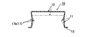
- FIG. 2 is a cross-sectional explanatory view taken along line AA in FIG. 1.
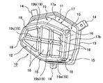
- the perspective view which shows 1st Embodiment of a buffer.
- Sectional explanatory drawing which follows the BB line of FIG. 3 which shows the crushing deformation
- Sectional explanatory drawing which follows the CC line of FIG. 3 which shows the crushing deformation
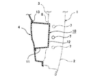
- Sectional drawing similar to FIG. 2 which shows the example from which the arrangement
- the perspective view which shows 2nd Embodiment of a buffer.
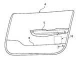
- the side door 1 is configured by a door outer panel 2 and a door inner panel 3 in a closed cross section.
- the door inner panel 3 constitutes a part of the side wall panel of the passenger compartment, and a door trim 4 as a trim material is mounted on the side surface of the passenger compartment side.
- the door trim 4 is molded with an appropriate synthetic resin material, and a door armrest 5 is disposed at an intermediate portion in the vertical direction, and a door pocket 6 is formed at the lower side.
- a shock absorber 10 made of an elastomer resin or the like and having high impact absorption performance is disposed at a required portion of the door trim 4.
- the shock absorber 10 is formed in a rectangular tube shape with one side open, and when it receives a collision load F in the vehicle width direction between the door inner panel 3 and the door trim 4 at the time of a side collision of the vehicle, it is crushed and deformed. It absorbs collision energy.
- the shock absorber 10 is disposed in a space portion between the door inner panel 3 and the door trim 4 with the peripheral wall 11 of the trunk portion facing sideways, and is crushed and deformed in the axial direction with respect to the collision load F described above. By absorbing the collision energy.
- This collision energy absorption characteristic is uniquely determined by the axial deformation stroke and the deformation reaction force of the shock absorber 10.
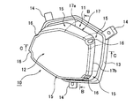
- the buffer body 10 is formed in a hexagonal rectangular tube shape that is horizontally long in the vehicle longitudinal direction.
- a flange portion 13 protruding outward is integrally formed on the periphery of the opening portion on one side, and the opening portion side on which the flange portion 13 is formed is arranged facing the back surface of the door trim 4.
- the shock absorber 10 is fixed to the door trim 4, for example, by projecting a plurality of bracket portions 14 in the vicinity of the flange portion 13 of the shock absorber 10 and projecting on the back surface of the door trim 4 with respect to the bracket portion 14. This can be done by caulking and fixing the boss part of the heat.
- This shock absorber 10 is disposed horizontally in the vehicle front-rear direction as described above in the impact area corresponding to the waist of the seated occupant in the door trim 4 for the purpose of occupant protection measures at the time of a side collision of the vehicle.
- the door trim 4 Since the door armrest 5 and the door pocket 6 are installed as described above, the door trim 4 has a flat and uneven surface as shown in FIG.
- the shock absorber 10 has the side surface shape on the opening portion side where the flange portion 13 facing the door trim 4 is formed as a side surface shape that matches the undulation of the modeling surface of the door trim 4, while the door inner panel 3 on the other side is formed.
- the opposing end walls 12 are formed flat so as to maintain parallelism with the door inner panel 3.
- the buffer body 10 is not uniform in height in the axial direction, and the height is different in each part, and the rigidity in the axial direction is different in each part according to the height dimension. .
- the flange portion 13 is formed on the periphery of the opening portion of the shock absorber 10 so that it can be uniformly pressed against the back surface of the door trim 4, and each adjacent side wall of the peripheral wall 11 is also provided.
- the mutual connecting portions 15 are formed as arcuate surfaces, and a buckling adjusting slit 16 is formed at a substantially top portion thereof.
- the buckling adjustment slit 16 is formed between a corner portion having a required die-cut surface where the peripheral wall 11 and the end wall 12 are adjacent to each other and a molding base portion of the flange portion 13 having the same required die-cut surface. It is provided in the range.
- the buckling adjustment slits 16 can be provided at all the connecting portions 15 of the peripheral wall 11 with their molding lengths being arbitrarily different from each other. However, in this embodiment, the laterally long buckling rigidity tends to increase.
- the buckling adjustment slit 16 is set in the end portion in the direction and the continuous portion 15 on the wall surface side where the molding height is lowered.
- the buckling adjustment slit 16 is located at a required height dimension, for example, a height of 10 mm or more from the molding base of the flange portion 13. It is desirable to set the slit toe.
- the notched corners of the buckling adjustment slit 16 are formed in an arc shape to suppress the occurrence of cracks due to stress concentration.
- the radius of curvature of the above-described continuous portion 15 and the length dimension of the buckling adjustment slit 16 are arbitrary depending on the plate thickness of the peripheral wall 11, the continuous angle between adjacent side walls, the height dimension of the peripheral wall 11, or the like. Set to For example, when the thickness of the peripheral wall 11 is 1 mm to 4 mm, the curvature radius of the continuous portion 15 is 20 mm to 40 mm, the buckling adjustment slit 16 is 10 mm, and the maximum length is the flange portion 13 side.
- the molding length from the continuous corners to the continuous corners of the end wall 12 can be used.
- shock absorber 10 includes a broken line 17 connected to the peripheral wall 11 in an annular shape.
- the bent line 17 is an outward bent line 17 a that protrudes radially outward on the vertical side wall of the peripheral wall 11, and an inward bent line that protrudes radially inward on the front and rear side wall.
- these broken lines 17a and 17b are formed in an annular shape that is continuous in the circumferential direction.
- the door inner panel 3 is deformed to the compartment side due to a side collision of the vehicle and contacts the end wall 12 of the shock absorber 10.
- the collision load F is input in the axial direction, the periphery of the opening portion is uniformly pressed against the back surface of the door trim 4 by the flange portion 13.
- the buckling adjustment slit 16 Since the rigidity in the axial direction, that is, the buckling rigidity is adjusted, the cylindrical shape of the shock absorber 10 is crushed and deformed in the axial direction in an orderly manner.
- the buckling adjustment slit 16 provided in the continuous portion 15 of the peripheral wall 11 has a notch corner portion formed in an arc shape, so that the slit is formed when the shock absorber 10 is crushed in the axial direction.
- 16 expands in the circumferential direction of the peripheral wall 11 the occurrence of cracks due to stress concentration at the notch corners can be suppressed.
- the buckling rigidity of the connecting portion 15 can be reduced without being accompanied by a crack, and the effect of suppressing the deterioration of the robustness of the shock absorber 10 can be enhanced.
- the peripheral wall 11 can be buckled and deformed with the bent line 17 as a starting point, so that the axial deformation of the shock absorber 10 can be performed more orderly. it can.
- the fold line 17 is continuous in the circumferential direction as an outward fold line 17a protruding radially outward on the vertical side wall of the peripheral wall 11 and an inward fold line 17b protruding radially inward on the front and rear side wall. .
- the peripheral wall 11 is buckled at an angle with the side wall in the vertical direction facing outward, while the side wall in the front and back direction is buckled at an angle toward the inner side. It is possible to promote a more orderly axial crushing deformation without causing a protrusion or pull-in between the side walls.
- FIG. 7 shows an example in which the buffer body 10 is arranged differently.
- an impact beam 7 is disposed in the vehicle front-rear direction in a closed cross section between the door outer panel 2 and the door inner panel 3, so that a buffering action at the time of a side collision and a door deformation to the vehicle compartment side. Inhibiting effect.
- the impact beam 7 is disposed at substantially the same height as the shock absorber 10 fixed on the back surface of the door trim 4, that is, at a height passing through the impact area of the seated occupant.
- the door inner panel 3 is formed with an open window 8 where the shock absorber 10 faces, so that the deformation movement of the impact beam 7 toward the passenger compartment is directly received by the end wall 12 of the shock absorber 10.
- the impact beam 7 is bent and deformed toward the passenger compartment side at the time of a side collision of the vehicle, thereby absorbing the collision energy and suppressing the amount of displacement of the side door 1 toward the passenger compartment side.
- the impact beam 7 comes into contact with the end wall 12 of the shock absorber 10, and the shock absorber 10 is crushed and deformed in the axial direction, thereby further absorbing the collision energy reduced by the bending deformation of the impact beam 7.
- the installation height of the impact beam 7 may differ slightly as shown by the chain line in FIG.
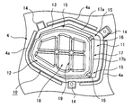
- FIG. 8 shows a shock absorber 10 suitable for use in the side door 1 having such a specification using the impact beam 7.
- the central portion of the end wall 12 is formed in a concavo-convex shape by a plurality of recessed portions 18 and a plurality of rib portions 19 partitioning these recessed portions 18.
- the rib portion 19 includes a circular portion 19a along the periphery of the end wall 12, two parallel vertical ribs 19b extending in the vertical direction, and one horizontal rib 19c extending in the front-rear direction.
- the portion surrounded by them is formed as a recessed portion 18.
- the end wall 12 is configured to be uneven by the plurality of recessed portions 18 and the plurality of rib portions 19, the surface rigidity of the end wall 12 is enhanced. .
- the impact beam 7 is displaced above or below the normal position indicated by the solid line, and the impact beam 7 is displaced either above or below the end wall 12 and displaced. Even if it hits, the collision load from the impact beam 7 is dispersed in the surface direction of the end wall 12.
- the collision load can be distributed almost uniformly in the axial direction on the peripheral wall 11, and the shock absorber 10 can be neatly deformed in the axial direction in the same manner as described above.
- the rib portion 19 is formed in a cross beam shape.
- the impact beam 7 intersects with two vertical beams that intersect with the impact beam 7 except for the above-described lateral rib 19 c. It may be received by the rib 19b and the annular rib 19a at the peripheral edge of the end wall.
- FIG. 10 shows different examples of the arrangement form of the buffer body 10.
- the rib protrusion 4a surrounding the flange portion 13 at the periphery of the opening portion of the shock absorber 10 is integrally formed on the back surface of the door trim 4 to which the shock absorber 10 is fixed.
- the shock absorber 10 of this embodiment when the shock absorber 10 is crushed and deformed in the axial direction at the time of a side collision of the vehicle, the rib protrusion 4a circumscribing the flange portion 13 in the diameter-expanding direction of the open side periphery Suppress with.
- the shock absorber 10 is disposed on the back surface of the impact area corresponding to the waist of the seated occupant in the door trim 4, but in addition to this, it corresponds to the waist and shoulders of the seated occupant in the rear side trim.
- the hexagonal square cylinder-shaped thing was illustrated as the buffer body 10, it is not limited to this, It is formed in the square cylinder shape by which one side was open
- the present invention can be applied to any polygonal shape and structure as long as it can absorb.
Abstract
Description
4 ドアトリム(トリム材)
4a リブ突起
10 緩衝体
11 周壁
12 端壁
13 フランジ部
15 周壁の連設部
16 座屈調整用スリット
17 周壁の折れ線
18 凹陥部
19 リブ部
Claims (5)
- 車室側の側壁パネル面を覆って装着されたトリム材の裏面に、該トリム材に対向した一側を開放してその周縁に外側に張り出すフランジ部を形成した合成樹脂製の角筒状の緩衝体を固着し、
車両の側面衝突時に前記緩衝体が衝突荷重を受けて圧潰変形することにより、衝突エネルギーを吸収可能とした構造であって、
前記緩衝体は、周壁の各隣接する側壁相互の連設部を円弧状に形成し、該円弧状の略頂部に周壁と端壁とが隣接した隅部と前記フランジ部の成形基部との間の範囲で、所要長さの座屈調整用スリットを前記衝突荷重の入力方向に形成したことを特徴とする自動車の車室側壁構造。 - 前記座屈調整用スリットは、その切欠隅部を円弧状に形成したことを特徴とする請求項1に記載の自動車の車室側壁構造。
- 前記緩衝体はその周壁に環状に連なる折れ線を備え、この折れ線を、上下方向の側壁と前後方向の側壁の何れか一方に設けた径方向外側に突出した外向き折れ線と、他方に設けた径方向内側に突出する内向き折れ線と、で構成したことを特徴とする請求項1に記載の自動車の車室側壁構造。
- 前記緩衝体の端壁の中央部分を、複数の凹陥部と、これら凹陥部を区画する複数のリブ部とで、凹凸形状に形成したことを特徴とする請求項1に記載の自動車の車室側壁構造。
- 前記トリム材は、前記緩衝体のフランジ部の周縁を囲繞するリブ突起を備えたことを特徴とする請求項1に記載の自動車の車室側壁構造。
Priority Applications (6)
| Application Number | Priority Date | Filing Date | Title |
|---|---|---|---|
| MX2015007345A MX358976B (es) | 2012-12-20 | 2013-12-16 | Estructura de pared lateral interior para un vehiculo. |
| CN201380062082.6A CN104884308B (zh) | 2012-12-20 | 2013-12-16 | 汽车的车厢侧壁构造 |
| US14/650,517 US9452727B2 (en) | 2012-12-20 | 2013-12-16 | Interior side wall structure for a vehicle |
| EP13865954.5A EP2937247B1 (en) | 2012-12-20 | 2013-12-16 | Automobile cabin side-wall structure |
| MYPI2015702048A MY185808A (en) | 2012-12-20 | 2013-12-16 | Automobile cabin side-wall structure |
| BR112015014650-3A BR112015014650B1 (pt) | 2012-12-20 | 2013-12-16 | Estrutura de parede lateral interior para um veículo |
Applications Claiming Priority (2)
| Application Number | Priority Date | Filing Date | Title |
|---|---|---|---|
| JP2012-277591 | 2012-12-20 | ||
| JP2012277591A JP5802190B2 (ja) | 2012-12-20 | 2012-12-20 | 自動車の車室側壁構造 |
Publications (1)
| Publication Number | Publication Date |
|---|---|
| WO2014097606A1 true WO2014097606A1 (ja) | 2014-06-26 |
Family
ID=50977968
Family Applications (1)
| Application Number | Title | Priority Date | Filing Date |
|---|---|---|---|
| PCT/JP2013/007384 WO2014097606A1 (ja) | 2012-12-20 | 2013-12-16 | 自動車の車室側壁構造 |
Country Status (8)
| Country | Link |
|---|---|
| US (1) | US9452727B2 (ja) |
| EP (1) | EP2937247B1 (ja) |
| JP (1) | JP5802190B2 (ja) |
| CN (1) | CN104884308B (ja) |
| BR (1) | BR112015014650B1 (ja) |
| MX (1) | MX358976B (ja) |
| MY (1) | MY185808A (ja) |
| WO (1) | WO2014097606A1 (ja) |
Families Citing this family (20)
| Publication number | Priority date | Publication date | Assignee | Title |
|---|---|---|---|---|
| JP5802190B2 (ja) * | 2012-12-20 | 2015-10-28 | 河西工業株式会社 | 自動車の車室側壁構造 |
| JP6277259B2 (ja) * | 2014-02-24 | 2018-02-07 | 帝人株式会社 | 樹脂製衝撃吸収部材 |
| JP6383169B2 (ja) * | 2014-03-31 | 2018-08-29 | ダイハツ工業株式会社 | 車両側部構造 |
| JP6156291B2 (ja) * | 2014-09-01 | 2017-07-05 | トヨタ自動車株式会社 | 車両用ドア構造 |
| DE102015205779B4 (de) * | 2015-03-31 | 2021-02-25 | Bayerische Motoren Werke Aktiengesellschaft | Bedienelementengehäuse und Türinnenverkleidung mit einem solchen Bedienelementengehäuse |
| CN105539348B (zh) * | 2016-02-02 | 2018-05-08 | 东风伟世通汽车饰件系统有限公司 | 一种汽车门饰板用吸能器 |
| JP6540529B2 (ja) * | 2016-02-04 | 2019-07-10 | テイ・エス テック株式会社 | 車両用内装部品 |
| JP6608796B2 (ja) * | 2016-10-26 | 2019-11-20 | トヨタ自動車株式会社 | 車両用衝撃吸収構造 |
| US10336276B2 (en) * | 2017-01-05 | 2019-07-02 | Ford Global Technologies, Llc | Energy absorber with varying stiffness |
| US9950594B1 (en) * | 2017-03-09 | 2018-04-24 | Ford Global Technologies, Llc | Impact absorbing system for a vehicle |
| JP6649911B2 (ja) * | 2017-03-10 | 2020-02-19 | トヨタ紡織株式会社 | 衝撃吸収部材 |
| JP6769375B2 (ja) * | 2017-03-30 | 2020-10-14 | トヨタ紡織株式会社 | 乗物用機能部品取付け構造 |
| JP6807000B2 (ja) * | 2017-03-30 | 2021-01-06 | キョーラク株式会社 | 構造体 |
| JP6595534B2 (ja) * | 2017-06-30 | 2019-10-23 | アイシン精機株式会社 | モジュールパネル |
| JP7177337B2 (ja) * | 2017-08-02 | 2022-11-24 | テイ・エス テック株式会社 | 衝撃吸収体 |
| JP7121247B2 (ja) | 2017-08-02 | 2022-08-18 | テイ・エス テック株式会社 | 衝撃吸収体 |
| US10953820B2 (en) | 2018-03-20 | 2021-03-23 | Ford Global Technologies, Llc | Upper reinforcement for a door trim panel and method of tuning performance characteristics thereof |
| US10518615B2 (en) | 2018-03-20 | 2019-12-31 | Ford Global Technologies, Llc | Upper reinforcement for a door trim panel and method of tuning performance characteristics thereof |
| JP7131322B2 (ja) * | 2018-11-14 | 2022-09-06 | トヨタ自動車株式会社 | ドアサービスホールカバー |
| DE112019007806T5 (de) | 2019-10-10 | 2022-08-11 | Kasai Kogyo Co., Ltd. | Fahrzeugpolsterelement |
Citations (9)
| Publication number | Priority date | Publication date | Assignee | Title |
|---|---|---|---|---|
| JP2001080439A (ja) | 1999-09-17 | 2001-03-27 | Mitsubishi Motors Corp | エネルギ吸収部材 |
| US6779835B2 (en) * | 2001-12-06 | 2004-08-24 | Lear Corporation | Energy absorbing structure for automobile interior |
| JP2008513714A (ja) | 2004-09-22 | 2008-05-01 | フアウレシア・インネンラウム・ジステーメ・ゲゼルシヤフト・ミツト・ベシユレンクテル・ハフツング | 繊維材料から成る衝撃吸収装置 |
| JP2009012560A (ja) * | 2007-07-03 | 2009-01-22 | Kasai Kogyo Co Ltd | 自動車用内装部品 |
| JP2010264971A (ja) * | 2009-04-14 | 2010-11-25 | Toyota Boshoku Corp | 側突用樹脂衝撃吸収体の取付構造 |
| JP2011230571A (ja) | 2010-04-26 | 2011-11-17 | Kasai Kogyo Co Ltd | 自動車の車室側壁構造 |
| JP2012116244A (ja) * | 2010-11-29 | 2012-06-21 | Toyota Motor Corp | 車両用ドア構造 |
| JP2012240472A (ja) * | 2011-05-17 | 2012-12-10 | Kasai Kogyo Co Ltd | 自動車用内装部品とその衝撃吸収体 |
| JP2013184661A (ja) * | 2012-03-09 | 2013-09-19 | Kasai Kogyo Co Ltd | 自動車用内装部品 |
Family Cites Families (11)
| Publication number | Priority date | Publication date | Assignee | Title |
|---|---|---|---|---|
| JP2605015Y2 (ja) | 1993-08-13 | 2000-06-19 | テイ・エス テック株式会社 | ドアライニング用の衝撃緩衝部材 |
| JP3873565B2 (ja) * | 2000-02-29 | 2007-01-24 | マツダ株式会社 | 自動車用ドア |
| CN101796320A (zh) * | 2007-08-03 | 2010-08-04 | 株式会社普利司通 | 冲击能量吸收构件 |
| US8029041B2 (en) * | 2008-04-12 | 2011-10-04 | Ford Global Technologies, Llc | Door trim-integrated pelvic impact energy-absorbing construction for vehicle |
| US7677640B2 (en) * | 2008-05-23 | 2010-03-16 | Nissan Technical Center North America, Inc. | Panel assembly for a vehicle |
| US8011717B2 (en) * | 2009-03-03 | 2011-09-06 | Kasai Kogyo Co., Ltd | Automotive interior component |
| JP2011021673A (ja) * | 2009-07-15 | 2011-02-03 | Nifco Inc | 衝撃吸収部材及び衝撃吸収構造 |
| JP5731962B2 (ja) * | 2011-12-09 | 2015-06-10 | トヨタ紡織株式会社 | 衝撃吸収体の取付構造 |
| JP5628246B2 (ja) * | 2012-07-31 | 2014-11-19 | ビステオン グローバル テクノロジーズ インコーポレイテッド | 車両用衝撃吸収体及びそれを有する車両用内装部品 |
| JP5802190B2 (ja) * | 2012-12-20 | 2015-10-28 | 河西工業株式会社 | 自動車の車室側壁構造 |
| US9259995B2 (en) * | 2013-11-07 | 2016-02-16 | Toyota Motor Engineering & Manufacturing North America, Inc. | Energy absorbing component |
-
2012
- 2012-12-20 JP JP2012277591A patent/JP5802190B2/ja active Active
-
2013
- 2013-12-16 BR BR112015014650-3A patent/BR112015014650B1/pt not_active IP Right Cessation
- 2013-12-16 CN CN201380062082.6A patent/CN104884308B/zh active Active
- 2013-12-16 MY MYPI2015702048A patent/MY185808A/en unknown
- 2013-12-16 MX MX2015007345A patent/MX358976B/es active IP Right Grant
- 2013-12-16 EP EP13865954.5A patent/EP2937247B1/en active Active
- 2013-12-16 US US14/650,517 patent/US9452727B2/en active Active
- 2013-12-16 WO PCT/JP2013/007384 patent/WO2014097606A1/ja active Application Filing
Patent Citations (9)
| Publication number | Priority date | Publication date | Assignee | Title |
|---|---|---|---|---|
| JP2001080439A (ja) | 1999-09-17 | 2001-03-27 | Mitsubishi Motors Corp | エネルギ吸収部材 |
| US6779835B2 (en) * | 2001-12-06 | 2004-08-24 | Lear Corporation | Energy absorbing structure for automobile interior |
| JP2008513714A (ja) | 2004-09-22 | 2008-05-01 | フアウレシア・インネンラウム・ジステーメ・ゲゼルシヤフト・ミツト・ベシユレンクテル・ハフツング | 繊維材料から成る衝撃吸収装置 |
| JP2009012560A (ja) * | 2007-07-03 | 2009-01-22 | Kasai Kogyo Co Ltd | 自動車用内装部品 |
| JP2010264971A (ja) * | 2009-04-14 | 2010-11-25 | Toyota Boshoku Corp | 側突用樹脂衝撃吸収体の取付構造 |
| JP2011230571A (ja) | 2010-04-26 | 2011-11-17 | Kasai Kogyo Co Ltd | 自動車の車室側壁構造 |
| JP2012116244A (ja) * | 2010-11-29 | 2012-06-21 | Toyota Motor Corp | 車両用ドア構造 |
| JP2012240472A (ja) * | 2011-05-17 | 2012-12-10 | Kasai Kogyo Co Ltd | 自動車用内装部品とその衝撃吸収体 |
| JP2013184661A (ja) * | 2012-03-09 | 2013-09-19 | Kasai Kogyo Co Ltd | 自動車用内装部品 |
Non-Patent Citations (1)
| Title |
|---|
| See also references of EP2937247A4 |
Also Published As
| Publication number | Publication date |
|---|---|
| BR112015014650B1 (pt) | 2021-06-22 |
| EP2937247A4 (en) | 2016-07-20 |
| JP2014121887A (ja) | 2014-07-03 |
| EP2937247B1 (en) | 2018-08-15 |
| BR112015014650A2 (pt) | 2017-07-11 |
| US9452727B2 (en) | 2016-09-27 |
| US20150298637A1 (en) | 2015-10-22 |
| CN104884308A (zh) | 2015-09-02 |
| MX2015007345A (es) | 2015-09-10 |
| JP5802190B2 (ja) | 2015-10-28 |
| MX358976B (es) | 2018-09-11 |
| CN104884308B (zh) | 2017-01-18 |
| MY185808A (en) | 2021-06-09 |
| EP2937247A1 (en) | 2015-10-28 |
Similar Documents
| Publication | Publication Date | Title |
|---|---|---|
| WO2014097606A1 (ja) | 自動車の車室側壁構造 | |
| US8764096B2 (en) | Bumper assembly for vehicle | |
| US9399489B2 (en) | Vehicle-body front structure | |
| US8770638B2 (en) | Bumper beam assembly for vehicle | |
| JP4386036B2 (ja) | クラッシュボックス | |
| WO2012101810A1 (ja) | 自動車の前部構造 | |
| US9599181B2 (en) | Shock absorber | |
| WO2017033511A1 (ja) | 車両用ドアの衝撃吸収構造 | |
| US10286865B2 (en) | Crash box for vehicle | |
| JP5389508B2 (ja) | 自動車の車室側壁構造 | |
| JP4457302B2 (ja) | 自動車用衝撃吸収部材 | |
| US7744146B2 (en) | Reinforcement structure for upper portion of vehicle door | |
| JP7080397B2 (ja) | 車両用緩衝部材 | |
| JP5572122B2 (ja) | 自動車の車室側壁構造 | |
| KR102350011B1 (ko) | 충격흡수 기능을 갖는 범퍼 스테이 | |
| US9517742B2 (en) | Shock absorber member for vehicle, vehicle door panel assembly including shock absorber member and vehicle including door panel assembly | |
| KR101618952B1 (ko) | 차량용 크래쉬박스 | |
| JP7131322B2 (ja) | ドアサービスホールカバー | |
| JP2015033962A (ja) | 車体前部構造 | |
| JP4781212B2 (ja) | 自動車用衝撃吸収部材 | |
| JP2017136965A (ja) | 車両用緩衝部材 | |
| JP6470877B2 (ja) | 車両用衝撃吸収構造 | |
| JP5598768B2 (ja) | 自動車用内装部品 | |
| JP5554623B2 (ja) | 自動車の車室側壁構造 | |
| KR20080054303A (ko) | 차량용 범퍼 백빔 |
Legal Events
| Date | Code | Title | Description |
|---|---|---|---|
| 121 | Ep: the epo has been informed by wipo that ep was designated in this application |
Ref document number: 13865954 Country of ref document: EP Kind code of ref document: A1 |
|
| WWE | Wipo information: entry into national phase |
Ref document number: 14650517 Country of ref document: US |
|
| WWE | Wipo information: entry into national phase |
Ref document number: MX/A/2015/007345 Country of ref document: MX |
|
| WWE | Wipo information: entry into national phase |
Ref document number: IDP00201503759 Country of ref document: ID |
|
| NENP | Non-entry into the national phase |
Ref country code: DE |
|
| REG | Reference to national code |
Ref country code: BR Ref legal event code: B01A Ref document number: 112015014650 Country of ref document: BR |
|
| WWE | Wipo information: entry into national phase |
Ref document number: 2013865954 Country of ref document: EP |
|
| ENP | Entry into the national phase |
Ref document number: 112015014650 Country of ref document: BR Kind code of ref document: A2 Effective date: 20150618 |