WO2014065320A1 - プーリアームの支点軸受装置 - Google Patents
プーリアームの支点軸受装置 Download PDFInfo
- Publication number
- WO2014065320A1 WO2014065320A1 PCT/JP2013/078697 JP2013078697W WO2014065320A1 WO 2014065320 A1 WO2014065320 A1 WO 2014065320A1 JP 2013078697 W JP2013078697 W JP 2013078697W WO 2014065320 A1 WO2014065320 A1 WO 2014065320A1
- Authority
- WO
- WIPO (PCT)
- Prior art keywords
- seal
- pulley arm
- sleeve
- lip
- washer
- Prior art date
Links
Images


Classifications
-
- F—MECHANICAL ENGINEERING; LIGHTING; HEATING; WEAPONS; BLASTING
- F16—ENGINEERING ELEMENTS AND UNITS; GENERAL MEASURES FOR PRODUCING AND MAINTAINING EFFECTIVE FUNCTIONING OF MACHINES OR INSTALLATIONS; THERMAL INSULATION IN GENERAL
- F16C—SHAFTS; FLEXIBLE SHAFTS; ELEMENTS OR CRANKSHAFT MECHANISMS; ROTARY BODIES OTHER THAN GEARING ELEMENTS; BEARINGS
- F16C33/00—Parts of bearings; Special methods for making bearings or parts thereof
- F16C33/72—Sealings
- F16C33/74—Sealings of sliding-contact bearings
-
- F—MECHANICAL ENGINEERING; LIGHTING; HEATING; WEAPONS; BLASTING
- F16—ENGINEERING ELEMENTS AND UNITS; GENERAL MEASURES FOR PRODUCING AND MAINTAINING EFFECTIVE FUNCTIONING OF MACHINES OR INSTALLATIONS; THERMAL INSULATION IN GENERAL
- F16C—SHAFTS; FLEXIBLE SHAFTS; ELEMENTS OR CRANKSHAFT MECHANISMS; ROTARY BODIES OTHER THAN GEARING ELEMENTS; BEARINGS
- F16C11/00—Pivots; Pivotal connections
- F16C11/04—Pivotal connections
-
- F—MECHANICAL ENGINEERING; LIGHTING; HEATING; WEAPONS; BLASTING
- F16—ENGINEERING ELEMENTS AND UNITS; GENERAL MEASURES FOR PRODUCING AND MAINTAINING EFFECTIVE FUNCTIONING OF MACHINES OR INSTALLATIONS; THERMAL INSULATION IN GENERAL
- F16H—GEARING
- F16H7/00—Gearings for conveying rotary motion by endless flexible members
- F16H7/08—Means for varying tension of belts, ropes, or chains
- F16H7/10—Means for varying tension of belts, ropes, or chains by adjusting the axis of a pulley
- F16H7/12—Means for varying tension of belts, ropes, or chains by adjusting the axis of a pulley of an idle pulley
- F16H7/1254—Means for varying tension of belts, ropes, or chains by adjusting the axis of a pulley of an idle pulley without vibration damping means
- F16H7/1281—Means for varying tension of belts, ropes, or chains by adjusting the axis of a pulley of an idle pulley without vibration damping means where the axis of the pulley moves along a substantially circular path
-
- F—MECHANICAL ENGINEERING; LIGHTING; HEATING; WEAPONS; BLASTING
- F16—ENGINEERING ELEMENTS AND UNITS; GENERAL MEASURES FOR PRODUCING AND MAINTAINING EFFECTIVE FUNCTIONING OF MACHINES OR INSTALLATIONS; THERMAL INSULATION IN GENERAL
- F16C—SHAFTS; FLEXIBLE SHAFTS; ELEMENTS OR CRANKSHAFT MECHANISMS; ROTARY BODIES OTHER THAN GEARING ELEMENTS; BEARINGS
- F16C2361/00—Apparatus or articles in engineering in general
- F16C2361/63—Gears with belts and pulleys
-
- F—MECHANICAL ENGINEERING; LIGHTING; HEATING; WEAPONS; BLASTING
- F16—ENGINEERING ELEMENTS AND UNITS; GENERAL MEASURES FOR PRODUCING AND MAINTAINING EFFECTIVE FUNCTIONING OF MACHINES OR INSTALLATIONS; THERMAL INSULATION IN GENERAL
- F16H—GEARING
- F16H7/00—Gearings for conveying rotary motion by endless flexible members
- F16H7/08—Means for varying tension of belts, ropes, or chains
- F16H2007/0889—Path of movement of the finally actuated member
- F16H2007/0893—Circular path
Definitions
- This invention relates to a fulcrum bearing device for a pulley arm that supports a tension pulley for belt tension adjustment.
- a hydraulic auto tensioner is connected to a swingable pulley arm that supports a tension pulley.
- the adjustment force applied to the pulley arm from the tensioner urges the pulley arm in the direction in which the tension pulley presses the belt, and the tension change of the belt is absorbed by the hydraulic auto tensioner to keep the belt tension constant.
- the belt transmission device as described above is provided outside the engine, there is a possibility that foreign matters such as muddy water and dust may enter the fulcrum bearing portion which is the swing center of the pulley arm. Since the entry of the foreign matter impedes the swinging of the pulley arm, or the life of the bearing portion is significantly reduced, it is necessary to take measures to prevent the foreign matter from entering the fulcrum bearing portion.
- Patent Document 1 Conventionally known as a fulcrum bearing device of a pulley arm that has taken measures to prevent the intrusion of foreign matter is described in Patent Document 1 below.
- a sleeve serving as a fulcrum shaft is inserted into a shaft hole of a cylindrical boss provided in the pulley arm, and the sleeve is interposed between the sleeve and the inner diameter surface of the shaft hole.
- a slide bearing that relatively rotatably supports the pulley arm a washer is fitted to each of the small-diameter cylindrical portions formed at both ends of the sleeve, and a bolt inserted inside the sleeve is attached to the engine block.
- the sleeve and the washer are fixed by screwing and tightening the bolt, and the pulley arm is swingably supported around the sleeve.
- annular recess 62 having a diameter larger than that of the shaft hole 61 is provided at both ends of the shaft hole 61 in the boss portion 60, and a seal member 63 is incorporated in the recess 62.
- An annular base 63a provided on the seal member 63 is fitted to the end of the sleeve 64, and one of the seal lips 63b, 63c of the pair of oppositely arranged seal lips 63b and 63c connected to the base 63a is sealed.
- the boss portion in which the slide bearing 66 and the sleeve 64 are incorporated by the seal member 63 is brought into elastic contact with the side surface of the recess 62 and the tip portion of the other seal lip 63c is elastically contacted with the inner surface of the washer 65.
- the foreign matter such as muddy water and dust is prevented from entering the shaft hole 61 of 60.
- An object of the present invention is to provide a fulcrum bearing device for a pulley arm that can ensure a good sealing performance even when the pressure rises due to a temperature change inside the fulcrum bearing.
- a sleeve is inserted into a shaft hole provided in a boss portion of a pulley arm, and both ends of the sleeve are opposite to both end surfaces of the boss portion in the axial direction.
- the sleeve is fixed by tightening a bolt that is inserted into the sleeve and screwed into the arm attachment target, and the pulley arm is supported in a swingable manner at both ends of the shaft hole of the boss portion.
- the seal member is made of an elastic material.
- a cylindrical portion press-fitted into the inner diameter surface of the seal housing recess, an inwardly-shaped annular portion continuously provided on the outer end of the cylindrical portion, and an inner portion of the annular portion A cylindrical radial lip that is inclined obliquely inwardly from the inside of the cylindrical portion, and a configuration is adopted in which the distal end portion of the radial lip is in elastic contact with the outer diameter surface of the sleeve. is there.
- An annular part is connected to the outer end of the cylindrical part press-fitted into the inner diameter surface of the seal accommodating concave part, and the inside of the cylindrical part is inclined inward from the inner periphery of the annular part.
- the radial lip When the pressure rises, the radial lip is elastically deformed in the direction of reducing the diameter, and the tip end portion comes into stronger contact with the outer diameter surface of the sleeve, and a good sealing property is secured at the contact portion of the radial lip. It will be.
- An axial lip that is inclined obliquely outward is provided on the inner peripheral portion of the outer surface of the annular portion of the seal member, and the tip portion of the axial lip is elastically contacted with the inner surface of the washer.
- the radial lip elastically deforms radially outward and the contact pressure decreases.
- the directional lip is elastically deformed toward the washer and comes into strong contact with the inner surface of the washer, so that a good sealing property can be ensured even when the pressure inside the bearing is lowered from the outside.
- An L-shaped seal core having an inward flange whose outer surface is covered with an annular portion of the sealing member at one end of the cylindrical portion whose outer diameter surface and end surface are covered with the cylindrical portion of the sealing member
- the seal member can be reinforced with the seal core, so that the assemblability of the seal member can be improved and a stable assembled state can be obtained.
- an annular concave step portion is formed on the outer peripheral portion of the inner surface facing the end surface of the boss portion of the washer, and is fitted into the seal housing concave portion inside the concave step portion. And the movement of the pulley arm in the axial direction is restricted by the side surface of the concave step portion facing the end surface of the boss portion with a minute gap, and the axial lip is provided on the side surface of the circular bulge portion.
- the tip outer diameter in the natural state of the axial lip is smaller than the inner diameter of the cylindrical portion of the seal core, and the tip outer diameter of the axial lip in the state of elastic contact with the side surface of the circular bulge is the circular bulge.
- the sealing member that seals the open end of the boss part is a synthetic rubber with excellent wear resistance because the radial lip is in frictional contact with the outer diameter surface of the sleeve and the axial lip is in frictional contact with the inner surface of the washer. It is good to form with.
- examples of such rubber include nitrile rubber, hydrogenated nitrile rubber, ACM rubber, silicon rubber, and fluorine rubber.
- the seal member incorporated in the seal housing recess of the boss portion includes the cylindrical portion, the inwardly-circular ring portion continuously provided on the outer end of the cylindrical portion, and the circular ring.
- a tapered radial lip that is inclined obliquely inward from the inner periphery of the cylindrical portion, and the cylindrical portion is press-fitted into the inner diameter surface of the seal receiving recess, and the tip of the radial lip is connected to the sleeve Since the outer diameter surface is elastically contacted, when the pressure rises due to the temperature rise in the boss portion, the radial lip is elastically deformed in the direction to reduce the diameter, so that the tip of the radial lip contacts the outer diameter surface of the sleeve. The force is increased, a good sealing property can be secured at the contact portion of the radial lip, and entry of foreign matters can be stably prevented.
- FIG. 2 is a cross-sectional view taken along line II-II in FIG. It is an expanded sectional view of the fulcrum bearing part of FIG. It is an expanded sectional view of the built-in part of the seal member of FIG.
- A) is sectional drawing which shows the other example of a fulcrum bearing apparatus
- (b) is sectional drawing which expands and shows a part of (a).
- (A), (b) is sectional drawing which shows the other example of FIG. It is sectional drawing in the natural state of the sealing member shown to Fig.5 (a), (b).
- FIG. 1 shows a belt drive device for driving auxiliary equipment.
- a pulley arm 1 that is swingably supported, a tension pulley 2 that is rotatably supported at the swing side end of the pulley arm 1, and a direction in which the tension pulley 2 presses the belt B.
- a hydraulic auto tensioner 3 for urging the pulley arm 1.
- the pulley arm 1 has a cylindrical boss portion 4, a slide bearing 6 is incorporated in the shaft hole 5 of the boss portion 4, and a metal sleeve 7 is inserted into the slide bearing 6. Has been.
- the sleeve 7 is longer than the axial length of the boss portion 4, and is provided with small diameter cylindrical portions 7 a at both ends facing the outside from both ends of the boss portion 4, and a washer 8 is fitted to each outer periphery of the small diameter cylindrical portion 7 a. Yes.
- the washer 8 is made of metal and plated to give corrosion resistance.
- the sleeve 7 and the washer 8 are inserted into the sleeve 7 and fixed to the engine block 30 by tightening bolts 20 which are screwed into the engine block 30 as an arm attachment target.
- the pulley arm 1 is configured with the sleeve 7 and the washer 8 as a fulcrum shaft. It can be swung.
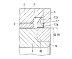
- seal housing recesses 11 having a diameter larger than that of the shaft hole 5 are formed at both ends of the shaft hole 5 in the boss portion 4, and a seal member 12 is incorporated in each of the seal housing recesses 11. It is.
- the seal member 12 has an inwardly-circular ring portion 12b continuously provided on the outer end of a cylindrical portion 12a that is press-fitted into the inner diameter surface of the seal housing recess 11, and the inner periphery of the ring portion 12b. It is made of a synthetic rubber molded product provided with a radial lip 12c at the part and provided with an axial lip 12d on the inner peripheral part of the outer surface of the annular part 12b. As synthetic rubber, rubber having excellent wear resistance is used. Examples of such rubber include nitrile rubber, hydrogenated nitrile rubber, ACM rubber, silicon rubber, and fluorine rubber.
- the seal core 12 is molded with the seal core 12 when the seal member 12 is molded.
- the seal core 13 has an L-shaped cross section in which an inward flange 13b is provided at one end of the cylindrical portion 13a, the outer diameter surface and the end surface of the cylindrical portion 13a are covered with the cylindrical portion 12a of the seal member 12, and The outer surface of the inward flange 13b is molded so as to be covered with the annular portion 12b, and the seal member 12 is reinforced.
- the radial lip 12c in the seal member 12 is tapered such that the inside of the cylindrical portion 12a is inclined obliquely inward, and the tip thereof is in elastic contact with the outer diameter surface of the sleeve 7. Further, the axial lip 12d is tapered so as to be inclined obliquely outward, and its tip is in elastic contact with the inner surface of the washer 8.
- An annular concave step portion 9 is formed on the outer peripheral portion of the inner surface facing the end surface of the boss portion 4 of the washer 8, and a circular bulging portion 10 is provided on the inner surface of the washer 8 by the formation of the concave step portion 9. Yes.
- the circular bulging portion 10 is fitted in the seal housing recess 11, and the tip end portion of the axial lip 12 d of the sealing member 12 is in elastic contact with the inner surface of the circular bulging portion 10.
- a chain line x in FIG. 4 indicates the natural state of the axial lip 12 d, and the distal end outer diameter D of the axial lip 12 d in the natural state is smaller than the inner diameter d of the cylindrical portion 13 a in the seal core 13. Further, the outer diameter of the tip end of the axial lip 12d in a state of elastic contact with the side surface of the circular bulge portion 10 is smaller than the outer diameter of the circular bulge portion 10, and the tip end portion of the axial lip 12d is circular bulge. The state which always contacts the side surface of the exit part 10 is ensured.
- the pulley arm fulcrum bearing device shown in the embodiment has the above-described structure, and the seal member 12 is assembled in the seal housing recess 11 in the previous stage where the washer 8 is fitted to the small diameter cylindrical portion 7a of the sleeve 7.
- the cylindrical end 12a is pressed into the inner diameter surface of the seal fitting recess 11 with the opening end of the cylindrical portion 12a first, and the distal end of the radial lip 12c is brought into elastic contact with the outer diameter surface of the sleeve 7. .
- the washer 8 is fitted to each of the small diameter cylindrical portions 7a at both ends of the sleeve 7.
- the washer 8 is fitted with the circular bulging portion 10 first. Since the circular bulging portion 10 presses the axial lip 12d by the fitting of the washer 8, the axial lip 12d is elastically deformed, and its distal end elastically contacts the side surface of the circular bulging portion 10 by its restoring elasticity. .
- the axial direction lip 12d is such that the tip outer diameter D in the natural state is smaller than the inner diameter d of the cylindrical portion 13a in the seal core 13 and is in elastic contact with the side surface of the circular bulging portion 10. Since the outer diameter of the tip of the axial lip 12d is smaller than the outer diameter of the circular bulging portion 10, the tip of the axial lip 12d is caught between the opposing portions of the boss 4 and the washer 8 when the washer 8 is assembled. There is no inconvenience. Further, it is possible to always ensure a state in which the tip end portion of the axial lip 12d is in elastic contact with the side surface of the circular bulge portion 10.
- the bolt 20 is inserted into the sleeve 7 and the bolt 20 is screwed into the engine block 30 and tightened, whereby the sleeve 7 and the washer 8 are fixed.
- the pulley arm 1 is swingably supported around the sleeve 7.
- the radial lip 12c provided in the seal member 12 is inclined obliquely inward, the radial lip 12c is elastically deformed in the direction of reducing the diameter by the pressure in the boss portion 4, and the front end. The portion is strongly pressed by the outer diameter surface of the sleeve 7. For this reason, a favorable sealing property is ensured at the tip contact portion of the radial lip 12c, and the entry of foreign matter from the outside is stably prevented.
- the lip portion 63 b of the seal 63 is moved to the side surface of the recess 62 in the boss portion 60 with relative rotation around the axis of the boss portion 60 and the sleeve 64 of the pulley arm.
- the lip portion 63b cannot be worn by sliding contact with the lip portion, and the sealing performance is deteriorated with the passage of time.
- an annular concave step portion 9 is formed on the outer peripheral portion of the inner side surface facing the boss end surface 4a of the washer 8. Then, the circular bulging portion 10 formed inside the concave step portion 9 is inserted into the seal housing concave portion 11 of the boss portion 4 to form a labyrinth seal L between the opposing portions of the boss portion 4 and the washer 8.
- the seal contact surface (inner surface) 8a of the washer 8 to the seal member 12 is positioned on the inner diameter side and the axially inner side with respect to the recessed step portion 9.
- the labyrinth seal L As described above, by forming the labyrinth seal L on the outer diameter side of the seal member 12, the labyrinth seal L exhibits a sealing performance, so that wear due to sliding contact with the boss portion 4 of the seal member 12 is suppressed. And the sealing performance can be maintained for a long time.
- the outer surface 8b of the washer 8 on the bolt insertion side with respect to the inside of the sleeve 7 is provided with a recess 8c in which the head of the bolt 20 is accommodated. Yes.
- the head of the bolt 20 enters the recess 8 c of the washer 8, thereby suppressing the height of the head, that is, the protruding height of the bolt 20 with respect to the boss portion 4.
- the seal member 12 incorporated in the seal housing recess 11 of the boss 4 is disposed in contact with the side surface 4d of the seal housing recess 11 facing outward in the axial direction. Further, the seal member 12 is fitted to the outer diameter surface 6b at both axial ends of the slide bearing 6, respectively.
- the seal member 12 is an annular member that is continuously formed without a break over the entire circumference.
- the seal member 12 is held between the inner side surface 8 a of the washer 8 and the side surface 4 d of the seal housing recess 11 in the boss portion 4 by a washer 8 fixed to the sleeve 7.
- a part of the labyrinth seal L is formed by a gap formed between the side surface 9 a of the recessed step portion 9 in the washer 8 and the end surface 4 a of the boss portion 4.
- the distance Lo1 between the side surfaces 9a facing the inner side in the axial direction of the concave step portion 9 is the distance between the axial ends of the boss portion 4 facing the same. It is set to be larger than the distance Lo2 between the end faces 4a and 4a. For this reason, a gap D is interposed between the side surface 9 a of the recessed step portion 9 and the end surface 4 a of the boss portion 4.
- a gap C is also interposed between the outer diameter surface 10a of the circular bulging portion 10 of the washer 8 and the inner diameter surface 4c of the seal housing recess 11 opposed thereto. Further, a space E for arranging the seal member 12 is interposed in the inner part.
- a labyrinth seal L is constituted by the gaps D and C and the space E.
- a gap C between the outer diameter surface 10 a of the circular bulging portion 10 of the washer 8 and the inner diameter surface 4 c of the seal housing recess 11 facing the washer 8 is formed on the sliding bearing 6 between the boss portion 4 and the sleeve 7. It is set to be larger than the radial gap.
- the radial clearance of the sliding bearing 6 between the boss 4 and the sleeve 7 is a dimension obtained by subtracting the radius of the outer diameter surface 7 b of the sleeve 7 from the radius of the inner diameter surface 6 c of the sliding bearing 6.
- the inner side surface 8a which is the contact portion of the washer 8 with the seal member 12, is located on the inner diameter side and the axially inner side with respect to the recessed step portion 9. Since the labyrinth seal L on the outer diameter side of the seal member 12 exhibits the sealing performance, wear due to the sliding contact of the sealing member 12 with the pulley arm 1 and the like can be suppressed, and the sealing performance can be maintained for a long time.
- the inner side surface 8a of the washer 8 is stepped as shown in FIG. 5 (b). That is, the concave step portion 9 is on the outer diameter side, the inner side surface 8 a of the washer 8 is on the inner diameter side, and the inner side surface 8 a enters the inner side in the axial direction from the end surface 4 a of the boss portion 4.
- the seal member 12 does not protrude outward in the axial direction from the end surface 4 a of the boss portion 4. If the washer 8 is fixed, the seal member 12 is compressed between the inner side surface 8a of the washer 8 and the side surface 4d of the seal housing recess 11, and is held between them. Thereby, protection of the sealing member 12 at the time of an assembly is achieved.
- the washer 8 is a pressed product.
- the inner surface 8a of the washer 8 can have a contact surface to the seal member 12 as a cutting surface or a grinding surface.
- rubber such as H-NBR or fluoro rubber can be used.
- the concave step portion 9 of the washer 8 and the end surface 4a of the boss portion 4 constitute a labyrinth seal L
- the side surfaces 9a, 9a facing the axially inner side of the concave step portion 9 located on both sides in the axial direction are arranged.
- the difference between the distance Lo1 and the distance Lo2 between the end faces 4a and 4a of the boss portion 4 opposite to the distance Lo1 is set to be smaller than the protruding length A in the axial direction of the circular bulging portion 10 of the washer 8. is required.
- the distance Li1 between the inner side surfaces 8a and 8a of the washer 8 positioned on both sides in the axial direction is set to be larger than the distance Li2 between the both end surfaces 6a and 6a of the sliding bearing 6 facing the washer 8, and the circular bulge portion thereof.
- a gap F is formed between the inner side surface 8 a of 10 and the bearing end surface 6 a of the slide bearing 6.
- the axial width W before the press-fitting of the seal member 12 shown in FIG. 7 includes a distance Lo1 between the side surfaces 9a and 9a of the recessed step portion 9, a distance Lo2 between both end surfaces 4a and 4a of the boss portion 4, and a circular bulge.
- Lo1-Lo2 + B ⁇ W is established.
- the sealing performance by the seal member 12 can be enhanced.
- the material of the sealing member 12 is free as long as a predetermined sealing property can be exhibited, but in this embodiment, a rubber material is used.
- the seal member 12 is fitted to the outer diameter surface 6b of the slide bearing 6 with a tightening margin.
- a one-lip seal provided with only one lip portion 12e protruding from the annular base portion 12f fitted to the outer diameter surface 6b of the slide bearing 6 to the outer diameter side is employed. ing. In the seal member 12, the lip portion 12 e comes into contact with the seal contact portion 31 of the washer 8.
- the labyrinth seal L can be configured while the sealing member 12 is held between the washer 8 and the boss portion 4 by making the inner surface of the washer 8 stepped.
- the seal member 12 can be made into one lip (single lip).
- chamfered portions 6d are respectively formed on a ridge line portion between the bearing end surface 6a and the outer diameter surface 6b on the outer side in the axial direction of the slide bearing 6 and a ridge line portion between the bearing end surface 6a and the inner diameter surface 6c on the outer side in the axial direction. Is provided.
- the seal member 12 can be smoothly inserted into the outer periphery of the slide bearing 6. Further, by providing the chamfered portion 6d, it is possible to prevent the seal member 12 from being caught between the slide bearing 6 and the washer 8 or the like.
- the axially outer bearing end surface 6 a of the slide bearing 6 is positioned on the axially outer side than the side surface 4 d of the seal housing recess 11 of the boss portion 4.
- the configuration of the seal member 12 includes an annular base portion 12f and a lip portion 12e that slidably contacts the inner side surface 8a of the washer 8 on the outer diameter side from the base portion 12f.
- the member 12 may be an O-ring having a circular cross section as shown in FIG. 6A, or an annular member having a rectangular cross section as shown in FIG. 6B.
- an axial clearance 67 is formed between the boss portion 60 of the pulley arm and the facing portion of the washer 65, and the boss portion 60 is within the range of the axial clearance 67.
- the seal member 63 is incorporated between the boss portion 60 that vibrates slightly and the washer 65 in a fixed state. Therefore, the seal member 63 includes the boss portion 60 that vibrates slightly and the boss portion 60 of the boss portion 60.
- the sliding bearing 66 that is fitted to the inner diameter surface and vibrates together with the boss portion 60 is repeatedly pressed, and the sealing member 63 is plastically deformed by the repeated pressing, and the sealing performance cannot be maintained. There is a fear.
- the seal member 12 housed in the seal housing recess 11 of the boss 4 is formed by the sleeve 7 and the washer 8.
- An axial clearance 14 formed between the inner surface of the seal member 12 and the side surface 4b of the seal housing recess 11 between the washer 8 and the opposing surface of the boss portion 4 is supported by the fulcrum shaft portion.
- a large gap 17 is provided so that the tips of the seal lips 12 h, 45, 49 provided on the outer periphery of the seal member 12 are brought into elastic contact with the inner diameter surface of the seal housing recess 11.
- the seal member 12 is provided with a seal lip 12h provided on the outer diameter surface of the annular portion 12g having a rectangular cross section and a tapered surface 12j provided on one side surface of the seal lip 12h. ing.
- the sealing member 12 has an annular portion 12g fitted into a cylindrical surface 16a of a concave step portion 16 formed at both end portions of the outer diameter surface of the sleeve 7, and an axial direction between the washer 8 and the side surface 16b of the concave step portion 16.
- the assembly is sandwiched from both sides, the outer surface is in close contact with the inner surface of the washer 8, and the tip of the seal lip 12h is in elastic contact with the inner diameter surface 4c of the seal housing recess 11.
- a gap 17 is provided between the inner surface 12 i of the seal member 12 and the side surface 4 d of the seal housing recess 11. Assuming that the size of the gap 17 is ⁇ 1 and the size of the axial clearance 11 formed between the opposed portions of the boss 4 and the washer 8 is ⁇ 2 , a size relationship that satisfies the relationship of ⁇ 1 > ⁇ 2 is established. Has been.
- the seal member 12 is supported by the fulcrum shaft portion formed by the sleeve 7 and the washer 8 and is in close contact with the inner surface of the washer 8, and the inner surface 12i of the seal member 12 and the side surface 4d of the seal housing recess 11 are provided.
- the seal member 12 can be used even if the boss portion slightly vibrates within the range of the axial clearance 14. There is no pressure. For this reason, there is no inconvenience that the sealing member 12 is plastically deformed, and good sealing performance can be ensured over a long period of time.
- a chamfer 40 is provided on the outer edge of the inner diameter surface of the sealing member 12, or a chamfer 41 is applied to the outer edge of the cylindrical surface of the concave step portion 16, as shown in FIG.
- the concave step portion 16 is formed at both ends of the sleeve 7, and the seal member 13 is supported by the cylindrical surface 14 a of the concave step portion 16, but as shown in FIG.
- a cylindrical portion 42 may be provided on the inner surface, and the sealing member 12 may be fitted and supported by the cylindrical portion 42.
- the seal member 12 can be attached to the cylindrical portion 42 before the washer 8 is assembled.
- the embeddability can be improved.
- the sealing member 12 is brought into close contact with the inner surface of the washer 8, and the inner diameter surface of the sealing member 12 is brought into close contact with the outer diameter surface of the cylindrical portion 42 to ensure sealing performance. May be. Alternatively, only the inner diameter surface of the seal member 12 may be brought into close contact with the outer diameter surface of the cylindrical portion 42 to ensure sealing performance.
- the seal member 12 is made of a rubber molded product in which a seal lip 12h is provided on the outer diameter surface of the annular portion 12g having a square cross section.
- the seal member 12 is not limited to this. It is not something.
- FIGS. 13 and 14 show other examples of the seal member 12.
- the seal member 12 shown in FIG. 13 has a configuration in which a tapered portion 44 is provided on the outer peripheral portion of an annular seal metal core 43 made of a thin metal plate, and a rubber seal lip 45 is fixed to the outer periphery of the tapered portion 44.
- the inner peripheral portion of the seal core 43 is sandwiched from both sides in the axial direction by the cylindrical portion 42 provided on the end surface of the sleeve 7 and the inner surface of the washer 8, and the outer surface of the seal core 43 is set to the end surface of the cylindrical portion 42.
- the seal lip 45 is elastically brought into contact with the inner diameter surface 4 c of the seal housing recess 11.
- a sealing metal core 46 made of a thin metal plate has an L-shaped cross section in which an inclined flange 48 is provided at one end of a cylindrical portion 47, and a rubber-made outer peripheral portion of the flange 48 is made.
- the seal lip 49 is fixed, the cylindrical portion 47 of the seal core 46 is fitted to the outer diameter surface of the end portion of the sleeve 7, and the outer end surface is brought into close contact with the inner surface of the washer 8.
- Elastic contact is made with the inner diameter surface 4 c of the seal housing recess 11.
Abstract
プーリアーム(1)に設けられたボス部(4)の軸孔(5)内にスリーブ(7)を挿入し、そのスリーブ(7)の両端部に形成された小径筒部(7a)のそれぞれ外周にワッシャ(8)を嵌合し、スリーブ(7)内に挿通されたボルト(20)の締め付けによりスリーブ(7)をエンジンブロック(30)に固定して、プーリアーム(1)を揺動自在に支持する。軸孔(5)の両端部に大径のシール収容凹部(11)を設け、そのシール収容凹部(11)内にシール部材(12)の外周部に設けられた円筒部(12a)を圧入する。シール部材(12)の内周に内方向に向けて傾斜する径方向リップ(12c)を設け、その径方向リップ(12c)の先端部をスリーブ(7)の外径面に弾性接触させ、内部圧力が上昇した際に、その径方向リップ(12c)が縮径する方向に弾性変形させるようにして、スリーブ(7)の外径面に対する接触圧力を高めるようにしたプーリアームの支点軸受装置である。
Description
この発明は、ベルトの張力調整用テンションプーリを支持するプーリアームの支点軸受装置に関する。
一般に、オルタネータやエアコンディショナ用のコンプレッサ、ウォータポンプ等のエンジン補機を駆動するベルト伝動装置においては、テンションプーリを支持する揺動可能なプーリアームに油圧式オートテンショナを連結し、その油圧式オートテンショナからプーリアームに負荷される調整力によってテンションプーリがベルトを押圧する方向にプーリアームを付勢し、ベルトの張力変化を上記油圧式オートテンショナにより吸収してベルトの張力を一定に保つようにしている。
上記のようなベルト伝動装置はエンジンの外部に設けられるため、プーリアームの揺動中心となる支点軸受部内に泥水やダスト等の異物が侵入するおそれがある。その異物の侵入によってプーリアームの揺動が阻害され、あるいは、軸受部の寿命が著しく低下するため、上記支点軸受部には異物の侵入防止対策が必要とされる。
異物の侵入防止対策を施したプーリアームの支点軸受装置として下記特許文献1に記載されたものが従来から知られている。
特許文献1に記載されたプーリアームの支点軸受装置においては、プーリアームに設けられた筒状のボス部の軸孔内に支点軸となるスリーブを挿入し、そのスリーブと軸孔の内径面間にスリーブとプーリアームを相対的に回転自在に支持するすべり軸受を組込み、上記スリーブの両端部に形成された小径筒部のそれぞれにワッシャを嵌合し、上記スリーブの内側に挿通されたボルトをエンジンブロックにねじ込み、そのボルトの締め付けによりスリーブおよびワッシャを固定して、スリーブを中心にプーリアームを揺動自在に支持している。
また、図15(a)に示すように、ボス部60における軸孔61の両端部に、その軸孔61より大径の環状の凹部62を設け、その凹部62内にシール部材63を組込み、そのシール部材63に設けられた環状の基部63aをスリーブ64の端部に嵌合し、その基部63aに連設された一対の相反する方向に傾斜するシールリップ63b、63cの一方のシールリップ63bにおける先端部を凹部62の側面に弾性接触し、他方のシールリップ63cの先端部をワッシャ65の内側面に弾性接触して、そのシール部材63によりすべり軸受66やスリーブ64が組み込まれたボス部60の軸孔61内に泥水やダスト等の異物が侵入するのを防止している。
特許文献1に記載された支点軸受装置においては、ベルトからの振動伝播によってプーリアームが高速度で揺動すると、すべり軸受66での接触摩擦により発熱し、その揺動中心となる支点軸受内部が高温になり易い。その支点軸受内の温度変化による内圧の上昇により、図15(b)に示すように、一方のシールリップ63bが外方に向けて弾性変形し、凹部62の側面から離反して密着性を保持することができず、外部からの異物侵入を防止することができなくなる。
この発明の課題は、支点軸受内部の温度変化により圧力が上昇した際でも良好なシール性を確保することができるようにしたプーリアームの支点軸受装置を提供することである。
上記の課題を解決するために、この発明においては、プーリアームのボス部に設けられた軸孔内にスリーブを挿入し、そのスリーブの両端部に前記ボス部の両端面と軸方向で対向するワッシャを設け、前記スリーブの内側に挿通されてアーム取付け対象にねじ込まれるボルトの締め付けによりスリーブを固定してプーリアームを揺動自在に支持し、前記ボス部の軸孔における両端部に、その軸孔より大径のシール収容凹部を設け、そのシール収容凹部内にシール部材を組み込んで、外部からボス部内への異物の侵入を防止するようにしたプーリアームの支点軸受装置において、前記シール部材が弾性材を素材として、前記シール収容凹部の内径面に圧入される円筒部と、その円筒部の外側端に連設された内向きの円環部と、その円環部の内周から前記円筒部内を斜め内方に向けて傾斜するテーパ状の径方向リップとを有してなり、前記径方向リップの先端部を前記スリーブの外径面に弾性接触させた構成を採用したのである。
シール収容凹部内に組み込まれるシール部材を、シール収容凹部の内径面に圧入される円筒部の外側端に円環部を連設し、その円環部の内周から上記円筒部内を斜め内方に向けて傾斜するテーパ状の径方向リップを設けた構成とし、その径方向リップの先端部をスリーブの外径面に弾性接触させることにより、プーリアームの揺動中心となるボス部内の温度上昇によって圧力が上昇すると、径方向リップが縮径する方向に弾性変形して先端部がスリーブの外径面により強く接触することになり、上記径方向リップの接触部において良好なシール性が確保されることになる。
シール部材における円環部の外側面の内周部に斜め外方に向けて傾斜する軸方向リップを設け、その軸方向リップの先端部をワッシャの内側面に弾性接触させることにより、ボス部内の温度低下によって圧力が低下し、その内部圧力が外部圧力より低くなると、径方向リップが径方向外方に向けて弾性変形して接触圧が低下することになるが、この場合、外部圧力により軸方向リップがワッシャに向けて弾性変形してワッシャの内側面に強く接触することになり、軸受内部の圧力が外部より低下した場合でも、良好なシール性を確保することができる。
また、シール部材の円筒部でもって外径面および端面が被覆される円筒部の一端にシール部材の円環部でもって外側面が被覆される内向きフランジが設けられた断面L形のシール芯金をシール部材に設けると、そのシール芯金でシール部材を補強することができるため、シール部材の組込み性を高めることができると共に、安定した組込み状態を得ることができる。
この発明に係るプーリアームの支点軸受装置において、ワッシャのボス部端面と対向する内側面の外周部に環状の凹段部を形成して、その凹段部の内側にシール収容凹部内に嵌合される円形膨出部を設け、上記ボス部の端面と微小間隙をおいて対向する上記凹段部の側面によりプーリアームの軸方向への移動を規制し、上記円形膨出部の側面に軸方向リップを弾性接触させるようにすると、軸方向リップが弾性接触する円形膨出部の側面はボス部端面からボス部内に入り込んで、微小間隙との間に距離が確保されるため、円形膨出部の側面に異物が付着してシール性が阻害されることが少なくなり、良好なシール性を長期にわたって維持することができる。
軸方向リップの自然状態での先端外径がシール芯金の円筒部の内径より小径とされ、円形膨出部の側面に弾性接触する状態での軸方向リップの先端外径を円形膨出部の外径より小径とすると、支点軸受装置の組立て時に軸方向リップの先端部がワッシャとボス部の対向面間に挟み込まれて損傷するのを防止することができる。
また、シール収容凹部の開口端における内周部に円形膨出部における側面の外周エッジとの間で間隙を形成するテーパ面を設けると、回転方向のガタの形成によりボス部が振れ回る状態でワッシャとの間で形成される微小間隙の範囲内で軸方向に移動したとしても、円形膨出部の外周がシール収容凹部の内径面に接触することはなく、プーリアームの揺動が阻害されるのを防止することができる。
ボス部の開口端を密閉するシール部材は、径方向リップがスリーブの外径面と摩擦接触し、また、軸方向リップがワッシャの内側面と摩擦接触するため、耐摩耗性に優れた合成ゴムで形成するのがよい。そのようなゴムとして、ニトリルゴム、水素化ニトリルゴム、ACMゴム、シリコンゴム、フッ素ゴムを挙げることができる。
この発明においては、上記のように、ボス部のシール収容凹部内に組み込まれるシール部材に、円筒部と、その円筒部の外側端に連設された内向きの円環部と、その円環部の内周から円筒部内を斜め内方に向けて傾斜するテーパ状の径方向リップとを設け、上記円筒部をシール収容凹部の内径面に圧入して、径方向リップの先端部をスリーブの外径面に弾性接触させるようにしたので、ボス部内の温度上昇による圧力上昇時には、径方向リップが縮径する方向に弾性変形するため、スリーブの外径面に対する径方向リップの先端部の密着力が高くなり、上記径方向リップの接触部において良好なシール性を確保することができ、異物の侵入を安定的に防止することができる。
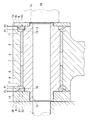
以下、この発明の実施の形態を図面に基づいて説明する。図1は補機駆動用ベルト伝動装置を示す。このベルト伝動装置においては、揺動可能に支持されたプーリアーム1と、そのプーリアーム1の揺動側端部に回転自在に支持されたテンションプーリ2と、そのテンションプーリ2がベルトBを押圧する方向にプーリアーム1を付勢する油圧式オートテンショナ3とからなっている。
図2に示すように、プーリアーム1は筒状のボス部4を有し、そのボス部4の軸孔5内にすべり軸受6が組み込まれ、そのすべり軸受6内に金属製のスリーブ7が挿入されている。
スリーブ7は、ボス部4の軸方向長さより長く、そのボス部4の両端から外部臨む両端部に小径筒部7aが設けられ、その小径筒部7aのそれぞれ外周にワッシャ8が嵌合されている。ワッシャ8は、金属製とされ、メッキ処理されて耐食性が付与されている。
スリーブ7およびワッシャ8は、スリーブ7内に挿入されてアーム取付け対象としてのエンジンブロック30にねじ込まれるボルト20の締め付けによりエンジンブロック30に固定され、そのスリーブ7およびワッシャ8を支点軸としてプーリアーム1が揺動可能とされている。
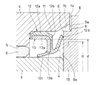
図3に示すように、ボス部4における軸孔5の両端部には、その軸孔5より大径のシール収容凹部11が形成され、そのシール収容凹部11のそれぞれ内部にシール部材12が組み込まれている。
図4に示すように、シール部材12は、シール収容凹部11の内径面に圧入される円筒部12aの外側端に内向きの円環部12bを連設し、その円環部12bの内周部に径方向リップ12cを設け、上記円環部12bの外側面の内周部に軸方向リップ12dを設けた合成ゴムの成形品からなっている。合成ゴムとして、耐摩耗性に優れたゴムが採用されている。そのようなゴムとして、ニトリルゴム、水素化ニトリルゴム、ACMゴム、シリコンゴム、フッ素ゴムを挙げることができる。
シール部材12は、その成形時にシール芯金13がモールドされる。シール芯金13は、円筒部13aの一端に内向きのフランジ13bを設けた断面L形とされ、上記円筒部13aの外径面および端面がシール部材12の円筒部12aで被覆され、また、内向きフランジ13bの外側面が円環部12bで被覆されるモールド成形とされて、シール部材12を補強している。
シール部材12における径方向リップ12cは、円筒部12aの内側を斜め内方に向けて傾斜するテーパ状とされ、その先端部がスリーブ7の外径面に弾性接触している。また、軸方向リップ12dは斜め外方に向けて傾斜するテーパ状とされ、その先端部がワッシャ8の内側面に弾性接触している。
ワッシャ8のボス部4端面と対向する内側面の外周部には環状の凹段部9が形成され、その凹段部9の形成によってワッシャ8の内側面に円形膨出部10が設けられている。円形膨出部10はシール収容凹部11内に嵌合し、その円形膨出部10の内側面にシール部材12の軸方向リップ12dの先端部が弾性接触している。
ここで、凹段部9の側面がボス部4の端面に接触していると、その接触部の摩擦によりプーリアーム1の揺動が阻害されることになるため、凹段部9の側面とボス部4の端面間には軸方向すきま14が設けられている。このため、ボス部4は、軸方向すきま14の範囲内において軸方向に移動可能とされて、上記凹段部9の側面によってボス部4の軸方向への移動が規制される。
また、上記軸方向すきま14の範囲内でボス部4が軸方向に移動する場合において、ボス部4の内側で回転方向のガタが生じると、ボス部4に振れ回りが生じ、円形膨出部10の外径面がシール収容凹部11の内径面に接触して、ボス部4の移動が阻害されることが考えられる。そこで、図4では、シール収容凹部11の開口端部にテーパ面15を設けて、円形膨出部10の側面における外周のエッジEとテーパ面15間に、ボス部4の軸方向の移動を許容する比較的大きな間隔を形成している。
図4において、同図の鎖線xは、軸方向リップ12dの自然状態を示し、その自然状態における軸方向リップ12dの先端外径Dはシール芯金13における円筒部13aの内径dより小径とされ、また、円形膨出部10の側面に弾性接触する状態での軸方向リップ12dの先端外径は円形膨出部10の外径より小径とされて、軸方向リップ12dの先端部が円形膨出部10の側面と常に接触する状態が確保されるようにしている。
実施の形態で示すプーリアームの支点軸受装置は上記の構造からなり、シール部材12の組付けは、スリーブ7の小径筒部7aにワッシャ8を嵌合する前段においてシール収容凹部11内に組み付ける。その組み付けは、円筒部12aの開口端を先にして、その円筒部12aをシール嵌合凹部11の内径面に圧入し、径方向リップ12cの先端部をスリーブ7の外径面に弾性接触させる。
上記のようなシール部材12の組み付け後、スリーブ7の両端の小径筒部7aのそれぞれにワッシャ8を嵌合する。この場合、円形膨出部10を先にしてワッシャ8を嵌合する。そのワッシャ8の嵌合により、円形膨出部10が軸方向リップ12dを押圧するため、軸方向リップ12dは弾性変形し、その復元弾性により先端部が円形膨出部10の側面に弾性接触する。
ここで、軸方向リップ12dは、自然状態での先端外径Dがシール芯金13における円筒部13aの内径dより小径とされ、また、円形膨出部10の側面に弾性接触する状態での軸方向リップ12dの先端外径が円形膨出部10の外径より小径とされているため、ワッシャ8の組み込み時にボス部4とワッシャ8の対向部間に軸方向リップ12dの先端が噛み込まれるという不都合の発生はない。また、軸方向リップ12dの先端部が円形膨出部10の側面に弾性接触する状態を常に確保することができる。
上記のようなシール部材12およびワッシャ8の組み付け後、スリーブ7内にボルト20を挿入し、そのボルト20をエンジンブロック30にねじ係合して締め付けると、スリーブ7およびワッシャ8が固定され、そのスリーブ7を中心にしてプーリアーム1が揺動自在の支持とされる。
図1および図2に示すように、プーリアーム1を揺動自在に支持し、そのプーリアーム1に油圧式オートテンショナ3の調整力を付与するベルトBの張力調整状態において、ベルトBの張力が変化するとプーリアーム1がスリーブ7を中心に揺動する。その揺動により、すべり軸受6での接触摩擦により発熱して温度上昇し、その温度変化によりボス部4内の圧力が上昇する。
このとき、シール部材12に設けられた径方向リップ12cは、斜め内方に向けて傾斜しているため、ボス部4内の圧力により径方向リップ12cは縮径する方向に弾性変形して先端部がスリーブ7の外径面により強く押し付けられることになる。このため、径方向リップ12cの先端接触部において良好なシール性が確保され、外部からの異物の侵入が安定的に防止されることになる。
ここで、エンジンの停止により、ボス部4内の温度が低下して圧力が低下し、その内部圧力が、外部圧力より低くなると、スリーブ7の外径面に対する径方向リップ12cの接触圧力が低下してシール性が低下する。しかし、このとき、外部圧力により軸方向リップ12dがワッシャ8に向けて弾性変形して、円形膨出部10の側面に強く接触することになる。したがって、ボス部4内の圧力が外部より低下した場合でも、良好なシール性が確保されることになり、異物の侵入は安定的に防止される。
図15に示す従来のプーリアームの支点軸装置においては、プーリアームのボス部60とスリーブ64との軸周りの相対回転に伴って、そのシール63のリップ部63bが、ボス部60における凹部62の側面に摺接して、リップ部63bの摩耗を避けることはできず、時間の経過とともにシール性が損なわれることになる。
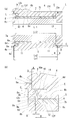
上記シール部材のシール性の低下を抑制するため、図5および図6に示す支点軸受装置においては、ワッシャ8のボス部端面4aと対向する内側面の外周部に環状の凹段部9を形成し、その凹段部9の内側に形成された円形膨出部10をボス部4のシール収容凹部11内に挿入してボス部4とワッシャ8の対向部間にラビリンスシールLを形成し、上記ワッシャ8のシール部材12へのシール接触面(内側面)8aを凹段部9よりも内径側且つ軸方向内側に位置させるようにしている。
上記のように、シール部材12よりも外径側にラビリンスシールLを形成することにより、そのラビリンスシールLがシール性を発揮するので、シール部材12のボス部4への摺接による摩耗を抑制し、そのシール性を長く維持することができる。
ここで、図5(a)(b)に示す支点軸受装置において、スリーブ7内に対するボルト挿入側のワッシャ8の外側面8bには、ボルト20の頭部が収容される凹部8cが設けられている。ボルト20の頭部が、このワッシャ8の凹部8cに入り込むことによって、頭部の高さ、すなわち、ボス部4に対するボルト20の突出高さを抑制している。
ボス部4のシール収容凹部11内に組み込まれたシール部材12は、シール収容凹部11の軸方向外方に向く側面4dに当接して配置されている。また、シール部材12は、すべり軸受6の軸方向両端部において、それぞれ、その外径面6bに嵌合されている。
シール部材12は、周方向全周に亘って切れ目なく連続的に形成された環状の部材である。シール部材12は、スリーブ7に固定されたワッシャ8によって、そのワッシャ8の内側面8aと、ボス部4におけるシール収容凹部11の側面4dとの間に保持される。
また、ワッシャ8における凹段部9の側面9aと、ボス部4の端面4aとの間に形成された隙間によってラビリンスシールLの一部を形成している。
軸方向両側に位置するワッシャ8間において、図5(a)に示すように、凹段部9の軸方向内側へ向く側面9a間の距離Lo1は、それに対向するボス部4の軸方向両端の端面4a、4a間の距離Lo2よりも大きく設定されている。このため、凹段部9の側面9aとボス部4の端面4aとの間に隙間Dが介在する。
また、ワッシャ8の円形膨出部10の外径面10aと、それに対向するシール収容凹部11の内径面4cとの間にも隙間Cが介在する。さらに、その奥部には、シール部材12を配置するための空間Eが介在する。これらの隙間D、C及び空間Eにより、ラビリンスシールLが構成されている。
なお、ワッシャ8の円形膨出部10の外径面10aと、それに対向するシール収容凹部11の内径面4cとの間の隙間Cは、ボス部4とスリーブ7との間のすべり軸受6のラジアル隙間よりも大きくなるように設定されている。ここで、ボス部4とスリーブ7との間のすべり軸受6のラジアル隙間とは、すべり軸受6の内径面6cの半径からスリーブ7の外径面7bの半径を差し引いた寸法である。ワッシャ8とボス部4との径方向の隙間Cを、すべり軸受6のラジアル隙間よりも大きくすることで、回転側であるボス部4と固定側であるワッシャ8との接触を避けることができる。
このように、ワッシャ8のシール部材12への当接部分である内側面8aは、凹段部9よりも内径側且つ軸方向内側に位置している。シール部材12よりも外径側のラビリンスシールLがシール性を発揮するので、シール部材12のプーリアーム1等への摺接による摩耗を抑制し、そのシール性を長く維持することができる。
また、ワッシャ8の内側面8aは、図5(b)に示すように、段付きとなっている。すなわち、凹段部9が外径側、ワッシャの8の内側面8aが内径側にあって、その内側面8aが、ボス部4の端面4aよりも軸方向内側に入り込む構成となっている。
このため、ワッシャ8のスリーブ7への取り付け前の状態において、シール部材12が、ボス部4の端面4aよりも軸方向外側に突出しないようになっており、ワッシャ8を固定すれば、シール部材12は、ワッシャ8の内側面8aとシール収容凹部11の側面4dとの間で圧縮されて、その間で保持されるようになっている。これにより、組立時におけるシール部材12の保護が図られている。
なお、この実施形態では、ワッシャ8はプレス加工品である。ワッシャ8の内側面8aは、そのシール部材12への接触面を切削面又は研削面とすることができる。シール部材12の素材としてはゴム、例えば、H-NBRやフッ素ゴムを採用することができる。
また、ワッシャ8の凹段部9と、ボス部4の端面4aとがラビリンスシールLを構成するために、軸方向両側に位置する凹段部9の軸方向内側へ向く側面9a、9a間の距離Lo1と、それに対向するボス部4の端面4a、4a間の距離Lo2との差は、そのワッシャ8における円形膨出部10の軸方向への突出長さAよりも小さく設定されていることが必要である。
また、軸方向両側に位置するワッシャ8における内側面8a、8a間の距離Li1が、それに対向するすべり軸受6の両端面6a、6a間の距離Li2よりも大きく設定されて、その円形膨出部10の内側面8aとすべり軸受6の軸受端面6aとの間に、隙間Fが形成されている。
このとき、Li1-Li2 > Lo1-Lo2 が成立するように部材の寸法を設定すれば、部材同士が軸方向へ相対移動した際に、すべり軸受6の軸受端面6aとが接触するよりも先に、ワッシャ8とボス部4とを接触させることができる。このため、ラビリンスシールLを構成する隙間を維持しやすい。
また、図7に示すシール部材12の圧入前における軸方向幅Wは、凹段部9の側面9a、9a間の距離Lo1、ボス部4の両端面4a、4a間の距離Lo2、円形膨出部10の側面8aとシール収容凹部11の側面4d間の軸方向幅Bとの関係において、Lo1-Lo2+B < W が成立するように設定されている。
このように、シール部材12が装着される空間の軸方向幅を、シール部材12の装着前の軸方向幅Wよりも小さくすることで、シール部材12によるシール性能を高めることができる。
なお、シール部材12の素材は、所定のシール性を発揮し得る限りにおいて自由であるが、この実施形態では、ゴム製のものを採用している。シール部材12は、すべり軸受6の外径面6bに締代をもって嵌められている。
また、この実施形態では、そのシール部材12として、すべり軸受6の外径面6bに嵌められる環状の基部12fから、外径側に突出するリップ部12eを一つだけ備えるワンリップシールを採用している。シール部材12は、このリップ部12eが、ワッシャ8のシール当接部31に接触する。
すなわち、ワッシャ8の内面を段付きとすることによって、シール部材12を、そのワッシャ8とボス部4との間に保持しながらラビリンスシールLを構成することができる。その結果、ラビリンスシールLによってある程度のシール性が期待できるので、シール部材12をワンリップ(単リップ)とすることを可能としたものである。
また、すべり軸受6の軸方向外側の軸受端面6aと外径面6bとの間の稜線部、及び、軸方向外側の軸受端面6aと内径面6cとの間の稜線部に、それぞれ面取り部6dが設けられている。
上記のように、面取り部6dを設けることにより、シール部材12のすべり軸受6の外周への挿入がスムーズである。また、面取り部6dを設けることにより、シール部材12がすべり軸受6とワッシャ8との間等に挟まる事態を防止することができる。
さらに、この実施形態では、すべり軸受6の軸方向外側の軸受端面6aは、ボス部4のシール収容凹部11の側面4dよりも軸方向外側に位置している。これにより、シール部材12とすべり軸受6とを軸方向に重複させて配置することができるので、すべり軸受6の軸方向寸法を充分に長く確保することができる。特に、シール部材12の軸方向幅に対し、その2/3以上をすべり軸受6で案内することが望ましく、この実施形態では、シール部材12の基部12fのほぼ全長をすべり軸受6で案内している。
この実施形態では、シール部材12の構成を、環状の基部12fと、その基部12fから外径側に立ち上がりワッシャ8の内側面8aに摺接するリップ部12eとを備えた構成としたが、このシール部材12を、例えば、図6(a)に示すように、断面円形を成すOリングとし、あるいは、図6(b)に示すように、断面矩形を成す環状部材としてもよい。
ここで、図15に示す従来のプーリアームの支点軸装置においては、プーリアームのボス部60とワッシャ65の対向部間に軸方向すきま67が形成され、その軸方向すきま67の範囲内でボス部60が軸方向に微振動し、その微振動するボス部60と固定状態にあるワッシャ65間にシール部材63が組み込まれているため、シール部材63は微振動するボス部60およびそのボス部60の内径面に嵌合されてボス部60と共に振動するすべり軸受66で繰り返し加圧されることになり、その繰り返しの加圧によりシール部材63が塑性変形して、シール性を維持することができなくなる恐れがある。
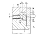
そのような不都合を解消するため、図8乃至図14に示すプーリアームの支点軸受装置においては、ボス部4のシール収容凹部11内に収容されたシール部材12をスリーブ7とワッシャ8とで形成される支点軸部で支持してワッシャ8に密着し、そのシール部材12の内側面とシール収容凹部11の側面4b間にワッシャ8とボス部4の対向面間に形成される軸方向すきま14より大きな間隙17を設け、上記シール部材12の外周に設けられたシールリップ12h、45、49の先端を上記シール収容凹部11の内径面に弾性接触させるようにしている。
図8および図9では、シール部材12として、断面が矩形とされた環状部12gの外径面にシールリップ12hを設け、そのシールリップ12hの一側面にテーパ面12jを設けたものを採用している。
上記シール部材12は、その環状部12gがスリーブ7の外径面両端部に形成された凹段部16の円筒面16aに嵌合され、ワッシャ8と凹段部16の側面16bとで軸方向両側から挟持されて、外側面がワッシャ8の内側面に密着し、シールリップ12hの先端部がシール収容凹部11の内径面4cに弾性接触する組付けとされている。
上記のようなシール部材12の組付け状態において、そのシール部材12の内側面12iとシール収容凹部11の側面4d間に間隙17が設けられる。その間隙17の大きさをδ1、ボス部4とワッシャ8の対向部間に形成された軸方向すきま11の大きさをδ2とすると、δ1>δ2の関係が成り立つ大きさ関係とされている。
上記のように、スリーブ7とワッシャ8で形成される支点軸部でシール部材12を支持してワッシャ8の内側面に密着し、そのシール部材12の内側面12iとシール収容凹部11の側面4d間にワッシャ8とボス部4の対向面間に形成される軸方向すきま14より大きな間隙を設けることにより、上記軸方向すきま14の範囲内でボス部が微振動しても、シール部材12は加圧されることはない。このため、シール部材12が塑性変形するという不都合の発生はなく、良好なシール性を長期にわたり確保することができる。
図10で示すように、シール部材12の内径面における外側端のエッジに面取り40を設け、あるいは、図11に示すように、凹段部16における円筒面の外側端のエッジに面取り41を施すことにより、シール部材12の組付け後におけるワッシャ8の組付け時に、そのシール部材12の外側面の内周部がワッシャ8とスリーブ7の対向面間に噛み込まれるのを防止することができる。
図9においては、スリーブ7の両端部に凹段部16を形成し、その凹段部16の円筒面14aでシール部材13を支持するようにしたが、図12に示すように、ワッシャ8の内側面に円筒部42を設け、その円筒部42でシール部材12を嵌合支持してもよい。
上記のように、ワッシャ8にシール部材12が嵌合支持される円筒部42を設けておくと、ワッシャ8の組付け前の状態で円筒部42にシール部材12を装着することができるため、組込み性を向上することができる。
図12に示すように、円筒部42の外径D1をスリーブ7の外径D2より大径(D1>D2)としておくことにより、ワッシャ8の組付け時に、シール部材12の内側面の内周部が円筒部42とスリーブ7の対向面間に噛み込まれるのを防止することができる。
なお、図12に示す場合においては、ワッシャ8の内側面にシール部材12を密着させ、かつ、シール部材12の内径面を円筒部42の外径面に密着させてシール性を確保するようにしてもよい。あるいは、シール部材12の内径面のみを円筒部42の外径面に密着させてシール性を確保するようにしてもよい。
図9では、シール部材12として、断面形状が角形とされた環状部12gの外径面にシールリップ12hを設けたゴムの成形品からなるものを示したが、シール部材12はこれに限定されるものではない。
図13および図14はシール部材12の他の例を示す。図13に示すシール部材12は、薄金属板からなる環状のシール芯金43の外周部にテーパ部44を設け、そのテーパ部44の外周にゴム製のシールリップ45を固着した構成とし、上記シール芯金43の内周部をスリーブ7の端面とワッシャ8の内側面に設けられた円筒部42で軸方向の両側から挟持して、シール芯金43の外側面を円筒部42の端面に密着させ、シールリップ45をシール収容凹部11の内径面4cに弾性接触させるようにしている。
図14に示すシール部材12においては、薄金属板からなるシール芯金46を円筒部47の一端に傾斜状のフランジ48を設けた断面L字状とし、そのフランジ48の外周部にゴム製のシールリップ49を固着した構成とし、上記シール芯金46の円筒部47をスリーブ7の端部外径面に嵌合して、その外端面をワッシャ8の内側面に密着させ、シールリップ49をシール収容凹部11の内径面4cに弾性接触させるようにしている。
1 プーリアーム
2 テンションプーリ
4 ボス部
5 軸孔
7 スリーブ
8 ワッシャ
9 凹段部
10 円形膨出部
11 シール収容凹部
12 シール部材
12a 円筒部
12b 円環部
12c 径方向リップ
12d 軸方向リップ
13 シール芯金
13a 円筒部
13b 内向きフランジ
14 軸方向すきま
15 テーパ面
20 ボルト
30 エンジンブロック(アーム取付け対象)
2 テンションプーリ
4 ボス部
5 軸孔
7 スリーブ
8 ワッシャ
9 凹段部
10 円形膨出部
11 シール収容凹部
12 シール部材
12a 円筒部
12b 円環部
12c 径方向リップ
12d 軸方向リップ
13 シール芯金
13a 円筒部
13b 内向きフランジ
14 軸方向すきま
15 テーパ面
20 ボルト
30 エンジンブロック(アーム取付け対象)
Claims (7)
- プーリアームのボス部に設けられた軸孔内にスリーブを挿入し、そのスリーブの両端部に前記ボス部の両端面と軸方向で対向するワッシャを設け、前記スリーブの内側に挿通されてアーム取付け対象にねじ込まれるボルトの締め付けによりスリーブを固定してプーリアームを揺動自在に支持し、前記ボス部の軸孔における両端部に、その軸孔より大径のシール収容凹部を設け、そのシール収容凹部内にシール部材を組み込んで、外部からボス部内への異物の侵入を防止するようにしたプーリアームの支点軸受装置において、
前記シール部材が弾性材を素材として、前記シール収容凹部の内径面に圧入される円筒部と、その円筒部の外側端に連設された内向きの円環部と、その円環部の内周から前記円筒部内を斜め内方に向けて傾斜するテーパ状の径方向リップとを有してなり、前記径方向リップの先端部を前記スリーブの外径面に弾性接触させたことを特徴とするプーリアームの支点軸受装置。 - 前記シール部材における円環部の外側面内周部に斜め外方に向けて傾斜する軸方向リップを設け、その軸方向リップの先端部を前記ワッシャの内側面に弾性接触させた請求項1に記載のプーリアームの支点軸受装置。
- 前記シール部材が、シール芯金により補強され、そのシール芯金が、円筒部の一端に内向きフランジが設けられて断面L形とされ、前記円筒部の外径面および端面が前記シール部材の円筒部で被覆され、内向きフランジの外側面が前記シール部材の円環部で被覆された請求項1又は2に記載のプーリアームの支点軸受装置。
- 前記ワッシャの前記ボス部の端面と対向する内側面の外周部に環状の凹段部を形成して、その凹段部の内側に前記シール収容凹部内に嵌合される円形膨出部を設け、前記ボス部の端面と微小間隙をおいて対向する前記凹段部の側面によりプーリアームの軸方向への移動を規制し、前記円形膨出部の側面に前記軸方向リップを弾性接触させた請求項1乃至3のいずれか1項に記載のプーリアームの支点軸受装置。
- 前記軸方向リップの自然状態での先端外径が前記シール芯金の円筒部の内径より小径とされ、前記円形膨出部の側面に弾性接触する状態での軸方向リップの先端外径が円形膨出部の外径より小径とされた請求項4に記載のプーリアームの支点軸受装置。
- 前記シール収容凹部の開口端における内周部に前記円形膨出部の外周エッジとの間で間隙を形成するテーパ面を設けた請求項4又は5に記載のプーリアームの支点軸受装置。
- 前記シール部材が、ニトリルゴム、水素化ニトリルゴム、ACMゴム、シリコンゴム、フッ素ゴムのいずれか1種の合成ゴムからなる請求項1乃至6のいずれか1項に記載のプーリアームの支点軸受装置。
Priority Applications (3)
| Application Number | Priority Date | Filing Date | Title |
|---|---|---|---|
| CN201380054483.7A CN104736891B (zh) | 2012-10-25 | 2013-10-23 | 带轮臂的支点轴承装置 |
| EP13849760.7A EP2913556B1 (en) | 2012-10-25 | 2013-10-23 | Support point bearing device for pulley arm |
| US14/438,233 US9581199B2 (en) | 2012-10-25 | 2013-10-23 | Fulcrum bearing device for pulley arm |
Applications Claiming Priority (6)
| Application Number | Priority Date | Filing Date | Title |
|---|---|---|---|
| JP2012-235743 | 2012-10-25 | ||
| JP2012235743A JP6093544B2 (ja) | 2012-10-25 | 2012-10-25 | プーリアームの支点軸受装置 |
| JP2012-236297 | 2012-10-26 | ||
| JP2012236297A JP6093545B2 (ja) | 2012-10-26 | 2012-10-26 | プーリアームの支持構造及び補機用オートテンショナユニット |
| JP2012-249338 | 2012-11-13 | ||
| JP2012249338A JP6030414B2 (ja) | 2012-11-13 | 2012-11-13 | プーリアームの支点軸受装置 |
Publications (1)
| Publication Number | Publication Date |
|---|---|
| WO2014065320A1 true WO2014065320A1 (ja) | 2014-05-01 |
Family
ID=50544695
Family Applications (1)
| Application Number | Title | Priority Date | Filing Date |
|---|---|---|---|
| PCT/JP2013/078697 WO2014065320A1 (ja) | 2012-10-25 | 2013-10-23 | プーリアームの支点軸受装置 |
Country Status (4)
| Country | Link |
|---|---|
| US (1) | US9581199B2 (ja) |
| EP (1) | EP2913556B1 (ja) |
| CN (1) | CN104736891B (ja) |
| WO (1) | WO2014065320A1 (ja) |
Cited By (4)
| Publication number | Priority date | Publication date | Assignee | Title |
|---|---|---|---|---|
| CN107387734A (zh) * | 2017-06-29 | 2017-11-24 | 武汉船用机械有限责任公司 | 一种滑轮组件 |
| CN107386345A (zh) * | 2017-08-22 | 2017-11-24 | 青岛雷沃工程机械有限公司 | 耐高温施工挖掘机斗杆前端处配合结构及挖掘机 |
| WO2018110528A1 (ja) * | 2016-12-15 | 2018-06-21 | Ntn株式会社 | テンショナ装置の支持構造 |
| CN112443583A (zh) * | 2019-09-05 | 2021-03-05 | 斯凯孚公司 | 用于轮毂组件的密封装置 |
Families Citing this family (12)
| Publication number | Priority date | Publication date | Assignee | Title |
|---|---|---|---|---|
| US9581224B1 (en) * | 2013-03-16 | 2017-02-28 | Eric N. Anderfaas | Final drive chain adjuster for single and multi track vehicles |
| WO2015031220A1 (en) * | 2013-08-28 | 2015-03-05 | Borgwarner Inc. | High temperature valve shaft seal |
| CN107250579B (zh) * | 2015-02-23 | 2019-04-19 | 三菱电机株式会社 | 轴支承部的耐热结构及致动器 |
| US10718375B2 (en) * | 2016-05-16 | 2020-07-21 | Roller Bearing Company Of America, Inc. | Bearing system with self-lubrication features, seals, grooves and slots for maintenance-free operation |
| JP6709722B2 (ja) * | 2016-11-24 | 2020-06-17 | 株式会社ダイヤメット | 焼結軸受 |
| US10132356B2 (en) | 2017-02-22 | 2018-11-20 | Mijo Radocaj | Washer with step |
| CN110131415B (zh) * | 2018-02-09 | 2023-02-21 | 舍弗勒技术股份两合公司 | 张紧器 |
| CN109236964B (zh) * | 2018-11-17 | 2019-11-26 | 山东理工大学 | 一种在原位置改变皮带松紧度的张紧轮 |
| US11365763B2 (en) * | 2018-12-06 | 2022-06-21 | Danfoss Power Solutions Inc. | Cover plate and seal carrier that eliminates bearing endplay |
| US11261979B2 (en) * | 2020-02-15 | 2022-03-01 | Fmc Technologies, Inc. | Check valve pivot pin retainer seal |
| EP4136362A4 (en) * | 2020-04-14 | 2024-01-10 | Pt Tech Llc | COMPACT, HIGH CAPACITY AND LONG LASTING CLUTCHES |
| CN114623154A (zh) * | 2022-04-01 | 2022-06-14 | 安徽日基焊接装备有限公司 | 一种新型结构的铝制转盘 |
Citations (6)
| Publication number | Priority date | Publication date | Assignee | Title |
|---|---|---|---|---|
| US790140A (en) | 1904-04-11 | 1905-05-16 | John Krepp | Nut-machine. |
| JPS60114372U (ja) * | 1984-01-12 | 1985-08-02 | エヌオーケー株式会社 | オイルシ−ル |
| JPH1089427A (ja) * | 1996-09-17 | 1998-04-07 | Otix:Kk | オートテンショナ用レバーアーム |
| JP2010255698A (ja) * | 2009-04-22 | 2010-11-11 | Nok Corp | 密封装置 |
| JP2011196552A (ja) * | 2007-07-03 | 2011-10-06 | Schaeffler Kg | 流体静力学的なリニアガイドのためのシール |
| JP2011231781A (ja) * | 2010-04-23 | 2011-11-17 | Nippon Valqua Ind Ltd | 摺動用シール材 |
Family Cites Families (51)
| Publication number | Priority date | Publication date | Assignee | Title |
|---|---|---|---|---|
| US2626839A (en) * | 1945-06-23 | 1953-01-27 | Ross Gear & Tool Co | Bearing seal |
| US2683637A (en) * | 1952-03-15 | 1954-07-13 | O & S Bearing Company | Compound bearing |
| US3117796A (en) * | 1960-06-29 | 1964-01-14 | Illinois Milling Inc | Oil seal |
| US3825272A (en) * | 1971-05-19 | 1974-07-23 | Townsend Engineering Co | Face seal for food processing equipment |
| FR2329162A5 (fr) * | 1973-08-09 | 1977-05-20 | Poclain Sa | Dispositif destine a proteger une articulation |
| US3848881A (en) * | 1973-10-03 | 1974-11-19 | Int Packaging Corp | High pressure seal |
| US4015883A (en) * | 1973-10-23 | 1977-04-05 | Skf Industrial Trading And Development Company, B.V. | Annular sealing members and assemblies incorporating them |
| GB1462070A (en) * | 1974-02-05 | 1977-01-19 | Tronoh Mines Ltd | Bearings |
| US4323287A (en) * | 1979-10-03 | 1982-04-06 | The Torrington Company | Bearing seal |
| JPS60114372A (ja) | 1983-11-25 | 1985-06-20 | Toppan Printing Co Ltd | 糊付装置 |
| JP2532236B2 (ja) * | 1987-03-23 | 1996-09-11 | 富士重工業株式会社 | ねじ式オ−トテンシヨナ |
| DE8707880U1 (ja) * | 1987-06-03 | 1987-08-20 | Fag Kugelfischer Georg Schaefer Kgaa, 8720 Schweinfurt, De | |
| JPH0378169A (ja) | 1989-08-19 | 1991-04-03 | Tokico Ltd | 磁気ディスク装置 |
| FR2705936B1 (fr) * | 1993-06-04 | 1995-08-04 | Valeo Systemes Dessuyage | Dispositif d'essuie-glace comportant une articulation entre une manivelle et une bielle. |
| US5509737A (en) * | 1994-11-02 | 1996-04-23 | The Torrington Company | Bearing with a seal-thrust withstanding member |
| US5758541A (en) * | 1995-04-03 | 1998-06-02 | Koyo Chicago Rawhide Co., Ltd. | Engaging noise preventing device for gear transmission device |
| US5593362A (en) * | 1995-04-26 | 1997-01-14 | Jatco Corporation | Carrier structure for planetary gear system |
| DE19523647A1 (de) * | 1995-06-29 | 1997-01-02 | Schaeffler Waelzlager Kg | Spanneinrichtung für Zugmittel wie Riemen und Ketten |
| JPH09196071A (ja) * | 1996-01-22 | 1997-07-29 | Nippon Seiko Kk | シール装置付転がり軸受 |
| US5975547A (en) * | 1997-09-09 | 1999-11-02 | Sanford Acquisition Company | Steering knuckle assembly with lubrication system |
| US6676132B1 (en) * | 1999-09-27 | 2004-01-13 | Kojo Seiko Co., Ltd. | Seal and rotary assembly using the seal |
| JP2001165166A (ja) * | 1999-12-07 | 2001-06-19 | Daido Metal Co Ltd | コネクティングロッド用すべり軸受 |
| US6712519B2 (en) * | 2000-07-28 | 2004-03-30 | Bombardier-Rotax Gmbh | Sealed bearing |
| CN1164878C (zh) * | 2001-03-13 | 2004-09-01 | 日立建机株式会社 | 密封装置 |
| WO2004097234A1 (ja) * | 2003-05-02 | 2004-11-11 | Komatsu Ltd. | 軸受シール及び回動装置 |
| JP2004340248A (ja) * | 2003-05-15 | 2004-12-02 | Daido Metal Co Ltd | 摺動部材 |
| JP4540974B2 (ja) * | 2003-12-16 | 2010-09-08 | Ntn株式会社 | 補機駆動用ベルトの張力調整装置 |
| WO2005072387A2 (en) * | 2004-01-29 | 2005-08-11 | Glacier Garlock Bearings, Inc. | Bearing with integral seal |
| WO2005121613A1 (ja) * | 2004-06-07 | 2005-12-22 | Nok Corporation | シーリングシステム |
| US7367739B2 (en) * | 2004-08-02 | 2008-05-06 | Clark Equipment Company | Two component seal |
| US7461977B2 (en) | 2004-09-03 | 2008-12-09 | Exmark Manufacturing Company, Incorporated | Pivot assembly |
| DE102004061097A1 (de) * | 2004-12-18 | 2006-06-22 | Schaeffler Kg | Endprofilierung an Gleitlagergegenlaufpartnern zur Reduzierung der Flächenpressung |
| JP4809610B2 (ja) * | 2005-02-03 | 2011-11-09 | Ntn株式会社 | プーリアームの支点軸受装置 |
| DE102005031593A1 (de) | 2005-07-06 | 2007-01-11 | Schaeffler Kg | Abdichtung für das Lagerauge eines Spannsystems |
| JP2008133908A (ja) * | 2006-11-29 | 2008-06-12 | Nsk Ltd | シールリング付車輪支持用転がり軸受ユニット |
| DE102007036442A1 (de) * | 2007-08-02 | 2009-02-05 | Schaeffler Kg | Verfahren zur Herstellung einer Gleitlagerstelle bei einem Gussbauteil, das vorzugsweise als Spannhebel eines Riemenspanners ausgebildet ist sowie Gussbauteil selbst |
| JP2009103142A (ja) | 2007-10-19 | 2009-05-14 | Toyota Motor Corp | シール装置 |
| EP2055971B1 (en) * | 2007-11-03 | 2012-08-08 | Delaware Capital Formation, Inc. | Radial sliding bearing |
| US8308370B2 (en) * | 2008-02-25 | 2012-11-13 | Jtekt Corporation | Sealing device for bearing |
| JP5172444B2 (ja) | 2008-04-14 | 2013-03-27 | 日立建機株式会社 | 軸受装置 |
| JP2009275737A (ja) * | 2008-05-13 | 2009-11-26 | Toyota Industries Corp | ベルト張力調整装置 |
| US20100201072A1 (en) * | 2009-02-06 | 2010-08-12 | Wians Jeffrey A | One piece shaft seal apparatus and method |
| JP5328027B2 (ja) * | 2009-03-30 | 2013-10-30 | 内山工業株式会社 | 密封装置 |
| JP5376315B2 (ja) * | 2009-09-08 | 2013-12-25 | Ntn株式会社 | プーリアームの支点軸受装置 |
| JP5444270B2 (ja) * | 2011-02-23 | 2014-03-19 | オイレス工業株式会社 | 合成樹脂製のスラスト滑り軸受 |
| JP2012219889A (ja) * | 2011-04-07 | 2012-11-12 | Jtekt Corp | シール部材の製造方法 |
| WO2012145610A1 (en) * | 2011-04-21 | 2012-10-26 | Illinois Tool Works Inc. | Sealing for thrust bearing |
| JP5789524B2 (ja) * | 2012-01-17 | 2015-10-07 | 日立建機株式会社 | 建設機械の軸受装置 |
| JP2014139451A (ja) * | 2013-01-21 | 2014-07-31 | Nok Corp | 密封装置 |
| EP2853351B1 (en) * | 2013-09-27 | 2019-12-25 | Aktiebolaget SKF | Rotative assembly, method for dismounting a sealing element and extraction tool for dismounting a sealing element |
| JP2016017578A (ja) * | 2014-07-08 | 2016-02-01 | 株式会社ジェイテクト | シール及びカバー |
-
2013
- 2013-10-23 US US14/438,233 patent/US9581199B2/en active Active
- 2013-10-23 CN CN201380054483.7A patent/CN104736891B/zh active Active
- 2013-10-23 EP EP13849760.7A patent/EP2913556B1/en active Active
- 2013-10-23 WO PCT/JP2013/078697 patent/WO2014065320A1/ja active Application Filing
Patent Citations (6)
| Publication number | Priority date | Publication date | Assignee | Title |
|---|---|---|---|---|
| US790140A (en) | 1904-04-11 | 1905-05-16 | John Krepp | Nut-machine. |
| JPS60114372U (ja) * | 1984-01-12 | 1985-08-02 | エヌオーケー株式会社 | オイルシ−ル |
| JPH1089427A (ja) * | 1996-09-17 | 1998-04-07 | Otix:Kk | オートテンショナ用レバーアーム |
| JP2011196552A (ja) * | 2007-07-03 | 2011-10-06 | Schaeffler Kg | 流体静力学的なリニアガイドのためのシール |
| JP2010255698A (ja) * | 2009-04-22 | 2010-11-11 | Nok Corp | 密封装置 |
| JP2011231781A (ja) * | 2010-04-23 | 2011-11-17 | Nippon Valqua Ind Ltd | 摺動用シール材 |
Non-Patent Citations (1)
| Title |
|---|
| See also references of EP2913556A4 |
Cited By (4)
| Publication number | Priority date | Publication date | Assignee | Title |
|---|---|---|---|---|
| WO2018110528A1 (ja) * | 2016-12-15 | 2018-06-21 | Ntn株式会社 | テンショナ装置の支持構造 |
| CN107387734A (zh) * | 2017-06-29 | 2017-11-24 | 武汉船用机械有限责任公司 | 一种滑轮组件 |
| CN107386345A (zh) * | 2017-08-22 | 2017-11-24 | 青岛雷沃工程机械有限公司 | 耐高温施工挖掘机斗杆前端处配合结构及挖掘机 |
| CN112443583A (zh) * | 2019-09-05 | 2021-03-05 | 斯凯孚公司 | 用于轮毂组件的密封装置 |
Also Published As
| Publication number | Publication date |
|---|---|
| EP2913556A4 (en) | 2016-03-30 |
| US9581199B2 (en) | 2017-02-28 |
| US20150275976A1 (en) | 2015-10-01 |
| EP2913556B1 (en) | 2023-03-29 |
| EP2913556A1 (en) | 2015-09-02 |
| CN104736891B (zh) | 2017-12-01 |
| CN104736891A (zh) | 2015-06-24 |
Similar Documents
| Publication | Publication Date | Title |
|---|---|---|
| WO2014065320A1 (ja) | プーリアームの支点軸受装置 | |
| US5201529A (en) | Sealing device | |
| JP2009174683A (ja) | 樹脂プーリ付き軸受 | |
| JP5894542B2 (ja) | 改善されたシール要素接合部を有する低トルクシャフトシール | |
| US9958011B2 (en) | Bearing assembly having surface protrusions and a seal | |
| US5553949A (en) | Rolling contact bearing | |
| JP5066787B2 (ja) | 密封構造 | |
| JP6093544B2 (ja) | プーリアームの支点軸受装置 | |
| JP2005264999A (ja) | 密封装置 | |
| JP2009074589A (ja) | 密封装置 | |
| WO2020166686A1 (ja) | 転がり軸受 | |
| JP6093545B2 (ja) | プーリアームの支持構造及び補機用オートテンショナユニット | |
| JP6030414B2 (ja) | プーリアームの支点軸受装置 | |
| JP2003097725A (ja) | 密封装置 | |
| JP3138507U (ja) | 密封装置 | |
| JP2005325867A (ja) | 鉄道車両用軸受 | |
| JP5564180B2 (ja) | 密封装置、転がり軸受および車輪用転がり軸受 | |
| JP2009024807A (ja) | 密封装置 | |
| JP2021167647A (ja) | 転がり軸受 | |
| JP5293420B2 (ja) | 密封装置 | |
| JP2009024809A (ja) | 密封装置および転がり軸受装置 | |
| JP2007285477A (ja) | シールチェーン | |
| JP4893550B2 (ja) | 密封装置 | |
| JP2009127668A (ja) | 密封装置 | |
| JP2571659B2 (ja) | 転がり軸受の取付け構造 |
Legal Events
| Date | Code | Title | Description |
|---|---|---|---|
| 121 | Ep: the epo has been informed by wipo that ep was designated in this application |
Ref document number: 13849760 Country of ref document: EP Kind code of ref document: A1 |
|
| WWE | Wipo information: entry into national phase |
Ref document number: 14438233 Country of ref document: US |
|
| NENP | Non-entry into the national phase |
Ref country code: DE |
|
| WWE | Wipo information: entry into national phase |
Ref document number: 2013849760 Country of ref document: EP |