WO2014054590A1 - ローラコンベア及び板状体の検査装置、並びにガラス板の製造装置 - Google Patents
ローラコンベア及び板状体の検査装置、並びにガラス板の製造装置 Download PDFInfo
- Publication number
- WO2014054590A1 WO2014054590A1 PCT/JP2013/076582 JP2013076582W WO2014054590A1 WO 2014054590 A1 WO2014054590 A1 WO 2014054590A1 JP 2013076582 W JP2013076582 W JP 2013076582W WO 2014054590 A1 WO2014054590 A1 WO 2014054590A1
- Authority
- WO
- WIPO (PCT)
- Prior art keywords
- glass plate
- flow path
- liquid
- plate
- roller conveyor
- Prior art date
- Legal status (The legal status is an assumption and is not a legal conclusion. Google has not performed a legal analysis and makes no representation as to the accuracy of the status listed.)
- Ceased
Links
Images





Classifications
-
- B—PERFORMING OPERATIONS; TRANSPORTING
- B08—CLEANING
- B08B—CLEANING IN GENERAL; PREVENTION OF FOULING IN GENERAL
- B08B1/00—Cleaning by methods involving the use of tools
- B08B1/20—Cleaning of moving articles, e.g. of moving webs or of objects on a conveyor
-
- B—PERFORMING OPERATIONS; TRANSPORTING
- B08—CLEANING
- B08B—CLEANING IN GENERAL; PREVENTION OF FOULING IN GENERAL
- B08B3/00—Cleaning by methods involving the use or presence of liquid or steam
- B08B3/02—Cleaning by the force of jets or sprays
- B08B3/024—Cleaning by means of spray elements moving over the surface to be cleaned
-
- B—PERFORMING OPERATIONS; TRANSPORTING
- B24—GRINDING; POLISHING
- B24B—MACHINES, DEVICES, OR PROCESSES FOR GRINDING OR POLISHING; DRESSING OR CONDITIONING OF ABRADING SURFACES; FEEDING OF GRINDING, POLISHING, OR LAPPING AGENTS
- B24B9/00—Machines or devices designed for grinding edges or bevels on work or for removing burrs; Accessories therefor
- B24B9/02—Machines or devices designed for grinding edges or bevels on work or for removing burrs; Accessories therefor characterised by a special design with respect to properties of materials specific to articles to be ground
- B24B9/06—Machines or devices designed for grinding edges or bevels on work or for removing burrs; Accessories therefor characterised by a special design with respect to properties of materials specific to articles to be ground of non-metallic inorganic material, e.g. stone, ceramics, porcelain
- B24B9/08—Machines or devices designed for grinding edges or bevels on work or for removing burrs; Accessories therefor characterised by a special design with respect to properties of materials specific to articles to be ground of non-metallic inorganic material, e.g. stone, ceramics, porcelain of glass
- B24B9/10—Machines or devices designed for grinding edges or bevels on work or for removing burrs; Accessories therefor characterised by a special design with respect to properties of materials specific to articles to be ground of non-metallic inorganic material, e.g. stone, ceramics, porcelain of glass of plate glass
- B24B9/102—Machines or devices designed for grinding edges or bevels on work or for removing burrs; Accessories therefor characterised by a special design with respect to properties of materials specific to articles to be ground of non-metallic inorganic material, e.g. stone, ceramics, porcelain of glass of plate glass for travelling sheets
-
- F—MECHANICAL ENGINEERING; LIGHTING; HEATING; WEAPONS; BLASTING
- F16—ENGINEERING ELEMENTS AND UNITS; GENERAL MEASURES FOR PRODUCING AND MAINTAINING EFFECTIVE FUNCTIONING OF MACHINES OR INSTALLATIONS; THERMAL INSULATION IN GENERAL
- F16C—SHAFTS; FLEXIBLE SHAFTS; ELEMENTS OR CRANKSHAFT MECHANISMS; ROTARY BODIES OTHER THAN GEARING ELEMENTS; BEARINGS
- F16C33/00—Parts of bearings; Special methods for making bearings or parts thereof
- F16C33/30—Parts of ball or roller bearings
- F16C33/58—Raceways; Race rings
- F16C33/62—Selection of substances
-
- F—MECHANICAL ENGINEERING; LIGHTING; HEATING; WEAPONS; BLASTING
- F16—ENGINEERING ELEMENTS AND UNITS; GENERAL MEASURES FOR PRODUCING AND MAINTAINING EFFECTIVE FUNCTIONING OF MACHINES OR INSTALLATIONS; THERMAL INSULATION IN GENERAL
- F16C—SHAFTS; FLEXIBLE SHAFTS; ELEMENTS OR CRANKSHAFT MECHANISMS; ROTARY BODIES OTHER THAN GEARING ELEMENTS; BEARINGS
- F16C33/00—Parts of bearings; Special methods for making bearings or parts thereof
- F16C33/30—Parts of ball or roller bearings
- F16C33/66—Special parts or details in view of lubrication
- F16C33/6637—Special parts or details in view of lubrication with liquid lubricant
- F16C33/6659—Details of supply of the liquid to the bearing, e.g. passages or nozzles
-
- H—ELECTRICITY
- H10—SEMICONDUCTOR DEVICES; ELECTRIC SOLID-STATE DEVICES NOT OTHERWISE PROVIDED FOR
- H10P—GENERIC PROCESSES OR APPARATUS FOR THE MANUFACTURE OR TREATMENT OF DEVICES COVERED BY CLASS H10
- H10P72/00—Handling or holding of wafers, substrates or devices during manufacture or treatment thereof
- H10P72/04—Apparatus for manufacture or treatment
- H10P72/0402—Apparatus for fluid treatment
- H10P72/0406—Apparatus for fluid treatment for cleaning followed by drying, rinsing, stripping, blasting or the like
-
- H—ELECTRICITY
- H10—SEMICONDUCTOR DEVICES; ELECTRIC SOLID-STATE DEVICES NOT OTHERWISE PROVIDED FOR
- H10P—GENERIC PROCESSES OR APPARATUS FOR THE MANUFACTURE OR TREATMENT OF DEVICES COVERED BY CLASS H10
- H10P72/00—Handling or holding of wafers, substrates or devices during manufacture or treatment thereof
- H10P72/30—Handling or holding of wafers, substrates or devices during manufacture or treatment thereof for conveying, e.g. between different workstations
- H10P72/32—Handling or holding of wafers, substrates or devices during manufacture or treatment thereof for conveying, e.g. between different workstations between different workstations
- H10P72/3202—Mechanical details, e.g. rollers or belts
-
- H—ELECTRICITY
- H10—SEMICONDUCTOR DEVICES; ELECTRIC SOLID-STATE DEVICES NOT OTHERWISE PROVIDED FOR
- H10P—GENERIC PROCESSES OR APPARATUS FOR THE MANUFACTURE OR TREATMENT OF DEVICES COVERED BY CLASS H10
- H10P72/00—Handling or holding of wafers, substrates or devices during manufacture or treatment thereof
- H10P72/30—Handling or holding of wafers, substrates or devices during manufacture or treatment thereof for conveying, e.g. between different workstations
- H10P72/33—Handling or holding of wafers, substrates or devices during manufacture or treatment thereof for conveying, e.g. between different workstations into and out of processing chamber
- H10P72/3314—Continuous loading and unloading into and out of a processing chamber, e.g. transporting belts within processing chambers
-
- B—PERFORMING OPERATIONS; TRANSPORTING
- B65—CONVEYING; PACKING; STORING; HANDLING THIN OR FILAMENTARY MATERIAL
- B65G—TRANSPORT OR STORAGE DEVICES, e.g. CONVEYORS FOR LOADING OR TIPPING, SHOP CONVEYOR SYSTEMS OR PNEUMATIC TUBE CONVEYORS
- B65G49/00—Conveying systems characterised by their application for specified purposes not otherwise provided for
- B65G49/05—Conveying systems characterised by their application for specified purposes not otherwise provided for for fragile or damageable materials or articles
- B65G49/06—Conveying systems characterised by their application for specified purposes not otherwise provided for for fragile or damageable materials or articles for fragile sheets, e.g. glass
- B65G49/063—Transporting devices for sheet glass
- B65G49/064—Transporting devices for sheet glass in a horizontal position
Definitions
- the present invention relates to a roller conveyor, a plate-shaped inspection apparatus, and a glass plate manufacturing apparatus.
- a float manufacturing method using a forming method called a float method is known.
- the float manufacturing method is a forming step in which molten glass is supplied to the surface of a molten metal stored in a float bath and formed into a strip-shaped glass plate, and the strip-shaped glass plate is cut into a rectangular glass plate of a predetermined size and cut.
- a cutting and chamfering step for grinding the peripheral edge of the glass plate, a polishing step for polishing and removing fine irregularities and undulations on the polished surface of the glass plate by a polishing apparatus, and an inspection step are provided.
- the inspection process is a cleaning process of cleaning the glass plate after polishing with a high pressure water, and a drying / cleaning process of drying / cleaning the glass plate by spraying compressed air from an air knife nozzle onto the glass plate. And a flatness measuring step for measuring the flatness of the surface to be polished (ratio of the waviness height to the waviness pitch).
- the glass plate is manufactured into a glass plate having a thickness of 0.2 to 1.5 mm suitable for an FPD glass plate and high flatness.
- Patent Document 1 discloses a batch-type polishing apparatus for an FPD glass plate.
- the polishing apparatus of Patent Document 1 includes a film body including an adsorption sheet that adsorbs and holds a glass plate, and a film frame on which the adsorption sheet is stretched.
- the pressurized fluid is supplied between the film body and the carrier to which the film body is attached, and the surface to be polished of the glass plate adsorbed and held by the adsorption sheet is applied to the polishing pad by the pressure of the pressurized fluid. While pressing, the surface to be polished is polished by relatively rotating (spinning and / or revolving) the glass plate and the polishing pad.
- the surface to be polished of the glass plate polished by the polishing pad is a surface on which TFT (Thin Film Transistor) or CF (Color Filter) is manufactured in the FPD manufacturing process, and high-precision flatness is required. Surface.
- TFT Thin Film Transistor
- CF Color Filter
- the flatness measurement step it is inspected whether the flatness of the polished surface of the polished glass plate is within a standard value suitable for the production of TFT or CF.
- This flatness inspection is performed using, for example, a flatness measuring device (inspection device) disclosed in Patent Document 2.
- a pattern having periodic brightness and darkness is irradiated onto a glass plate, a pattern transmitted through the glass plate or a reflected pattern is received, and a shift in the brightness cycle in the received light image (glass plate)
- the light and dark of the region in the received light image having a size corresponding to the light and dark period in the pattern irradiated to the glass plate is averaged, and the glass is calculated based on the averaged signal. Calculate the flatness of the plate.
- the glass plate whose surface to be polished has been polished in the polishing step is inspected for the flatness of the surface to be polished by the inspection step (flatness measuring device), but the polished glass plate Since the slurry is adhered to the slurry, the slurry adhered to the glass plate is washed away by the cleaning process of the inspection process. Thereafter, in the flatness measuring device, in order to prevent erroneous detection due to water droplets and dust remaining on the glass plate, the water droplets and dust are removed by compressed air from the air knife nozzle in the drying / cleaning process of the inspection process, and the glass After the plate is dried and cleaned, the flatness is measured by a flatness measuring device. The flatness measurement is also performed by a glass plate manufacturing method that does not polish the glass plate, for example, a fusion method.
- the glass plate is continuously conveyed from the polishing device to the flatness measuring device by a roller conveyor composed of a plurality of rollers, but the roller bearing laid on the drying line having the air knife nozzle leaked from the bearing.
- a roller conveyor composed of a plurality of rollers
- resin bearings self-lubricating fluororesin or other bearings that do not use grease or bearings coated with resin such as fluororesin are used (hereinafter referred to as resin bearings).
- resin bearings self-lubricating fluororesin or other bearings that do not use grease or bearings coated with resin such as fluororesin are used (hereinafter referred to as resin bearings).
- resin bearings there is also a resin bearing having a ceramic rolling element.
- the present invention has been made in view of such circumstances, and is a roller conveyor in which rollers are supported by a resin bearing, and a roller conveyor and a plate-shaped body inspection device that can suppress scattering of dust generated from the resin bearing. And it aims at providing the manufacturing apparatus of a glass plate.
- the present invention provides a roller conveyor for transporting a plate-like body by means of a roller, a plurality of rollers arranged along a transport path of the plate-like body, a rolling element, and the rolling element.
- a resin bearing having an outer ring and an inner ring that are accommodated so as to be sandwiched and rollable, and rotatably supporting the shafts of the plurality of rollers, or a resin bearing coated with resin, the rolling element, and the rolling element
- a roller conveyor including a raceway surface of the outer ring in contact, a liquid supply device for supplying a liquid to the raceway surface of the inner ring in contact with the rolling element, and a cover surrounding the resin bearing.
- the liquid is supplied from the liquid supply device to the rolling element of the resin bearing, the raceway surface of the outer ring in contact with the rolling element, and the raceway surface of the inner ring in contact with the rolling element.
- Resin dust can be mixed into the liquid, and since the resin bearing is surrounded by the cover, scattering of the dust can be suppressed. Furthermore, since the liquid functions as a lubricant, the service life of the resin bearing is extended.
- the resin bearing is composed of an outer ring, an inner ring, a rolling element, and a cage.
- the raceway is a dust spot. It is a feature of the present invention that liquid is supplied to the dust generation location and the generated resin dust is contained in the liquid.
- the resin bearing of the present invention refers to one in which at least one member among the outer ring, inner ring, rolling element, and cage constituting the bearing is made of resin or coated with resin. However, if at least one of the members is exposed from bearing steel that is not coated with resin, the self-lubricating property of the resin bearing is reduced. For this reason, as a preferable structure of the resin bearing, all members are made of resin, or the bearing steel is coated with resin.
- the material of the resin when all the members of the resin bearing are made of resin is not particularly limited, but ultra high molecular weight polyethylene (UHMW-PE: ultra high molecular weight-polyethylene), polytetrafluoroethylene (PTFE: polytetrafluoroethylene), or poly Ether ether ketone (PEEK: polyetheretherketone) is preferred.
- UHMW-PE ultra high molecular weight polyethylene
- PTFE polytetrafluoroethylene
- PEEK poly Ether ether ketone
- the material of the resin to be coated is not particularly limited, but a fluororesin or a polyimide resin having self-lubricating properties is preferable.
- the material of the bearings (rolling elements, outer ring, and inner ring) is not particularly limited, but is preferably hard and wear-resistant ceramic or high carbon chrome steel.
- the outer ring, the inner ring, and the cage are made of ultra high molecular weight polyethylene, and the rolling elements are made of ceramics.
- the liquid supply device includes a holder member that holds the outer ring of the resin bearing, a holder member that includes the liquid flow path, and the liquid supplied to the inlet of the flow path of the holder member. It is preferable that a liquid circulation supply unit that supplies and circulates the liquid discharged from the outlet of the flow path to the inlet of the flow path is provided.
- the holder member that includes the holding portion that holds and fixes the outer ring of the resin bearing is provided with the liquid flow path, and therefore it is not necessary to provide the flow path separately from the holder member.
- the number of parts can be reduced.
- the liquid is supplied to the inlet of the flow path by the liquid circulation supply means, and is supplied to the rolling element of the resin bearing, the raceway surface of the outer ring in contact with the rolling element, and the raceway surface of the inner ring in contact with the rolling element while passing through the flow path. Is done.
- the liquid discharged from the outlet of the flow path is circulated and supplied to the inlet of the flow path by the liquid circulation supply means.
- a filter is provided in the liquid circulation path and dust mixed in the liquid is captured by this filter, a clean liquid can always be supplied to the flow path.
- the flow path of the holder member is provided on one side with the holding portion interposed therebetween, and the first flow path communicated with the inlet of the flow path and the holding portion sandwiched between A second flow path provided on the other side and communicated with an outlet of the flow path, and the first flow path and the second flow path are communicated via the holding portion. It is preferable.
- the liquid supplied from the inlet of the flow channel to the first flow channel flows through the first flow channel and flows into the holding unit.
- the liquid is supplied to the resin bearing held by the holding portion.
- the liquid supplied to the resin bearing flows into the second flow path from the holding portion, flows through the second flow path, and is discharged from the outlet of the flow path.
- the holder is closed with the liquid between the first flow path and the holding section and between the holding section and the second flow path.
- a dam member is provided, and a part of the rolling element of the resin bearing, a part of the raceway surface of the outer ring, and a part of the raceway surface of the inner ring are immersed in the liquid blocked by the holding part. It is preferred that
- the liquid supplied to the holding portion is blocked by the dam member, a part of the rolling element of the resin bearing, a part of the raceway surface of the outer ring, and a part of the raceway surface of the inner ring Is always immersed in the liquid. Thereby, scattering of the dust from a resin bearing can be suppressed significantly.
- the shaft of the roller is inserted into the inner ring of the resin bearing, and the shaft located on both sides of the inner ring is provided with a sliding prevention member, and the sliding prevention It is preferable that the end surface of the member is brought into contact with the end surface of the inner ring and fixed to the shaft by a stopper.
- the stopper action of the anti-sliding member prevents the roller shaft from sliding in the axial direction with respect to the inner ring, thereby preventing dust generation due to sliding.
- the amount of dust generation can be reduced compared to the conventional method. Thereby, scattering of dust can be further suppressed.
- the present invention provides a cleaning unit that cleans the plate-shaped body while transporting the plate-shaped body, and a drying unit that cleans the plate-shaped body cleaned by the cleaning unit while transporting the plate-shaped body.
- the plate-like body inspection apparatus comprising: a cleaning unit; and an inspection unit that inspects the plate-like body that has been dried and cleaned by the drying / cleaning unit.
- the roller conveyor of the invention is arranged in the drying / cleaning section, the frequency of occurrence of erroneous detection of the inspection apparatus due to the dust adhering to the plate-like body is reduced. It can be greatly reduced.
- the plate-like body is preferably a glass plate.
- the roller conveyor of the present invention is disposed in the drying / cleaning section of the glass plate inspection apparatus, the inspection accuracy of the glass plate is greatly improved.
- the present invention provides a molding part for molding molten glass into a strip-shaped glass plate, Cutting the chamfered glass plate into a rectangular glass plate of a predetermined size, and cutting and chamfering to grind the peripheral edge of the cut glass plate; A cleaning unit that cleans the peripheral edge of the glass plate while transporting, a drying / cleaning unit that cleans the glass plate cleaned by the cleaning unit while drying, and the drying / cleaning In the manufacturing apparatus of the glass plate provided with the inspection part which inspects the glass plate dried and cleaned by the chemical conversion part, A glass plate manufacturing apparatus in which a roller conveyor of the present invention is disposed in the drying / cleaning section is provided.
- the roller conveyor of the present invention is disposed in the drying / cleaning section of the glass plate inspection apparatus, it is possible to manufacture a glass plate with greatly improved inspection accuracy of the glass plate.
- roller conveyor of the present invention scattering of resin dust generated from the resin bearing can be suppressed.
- the inspection apparatus of the plate-shaped object of the present invention it is possible to greatly reduce the occurrence frequency of erroneous detection caused by the dust adhering to the plate-shaped object.
- FIG. 1 is a block diagram showing each process of a glass plate manufacturing apparatus and a glass plate inspection apparatus for a liquid crystal display.
- FIG. 2 is a plan view showing the configuration of the glass plate inspection apparatus of FIG.
- FIG. 3 is a side view showing the configuration of the cleaning device and the drying / cleaning device of the glass plate inspection device of FIG.
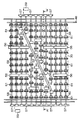
- FIG. 4 is a plan view showing the configuration of the roller conveyor in detail.
- FIG. 5 is a front view of the roller conveyor as viewed from line AA ′ in FIG.
- FIG. 6 is an assembled perspective view of the resin bearing and the holder member as viewed from above.
- FIG. 7 is a perspective view of the holder member of FIG. 6 as viewed from below.
- FIG. 5 is a front view of the roller conveyor as viewed from line AA ′ in FIG.
- FIG. 6 is an assembled perspective view of the resin bearing and the holder member as viewed from above.
- FIG. 7 is a perspective view of the holder member of FIG. 6 as
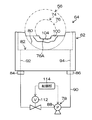
- FIG. 8 is a block diagram showing a configuration of a liquid supply apparatus including a holder member.
- FIG. 9 is a perspective view in which a resin bearing fixed to a holder member is surrounded by a cover.
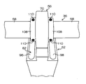
- FIG. 10 is a side view of the resin bearing and the holder member with the cover removed in FIG.
- a roller conveyor applied to a glass plate inspection apparatus (plate body inspection apparatus) installed in a glass plate manufacturing apparatus for a liquid crystal display
- the apparatus to which the roller conveyor of the present invention is applied is not limited to the glass plate inspection apparatus. That is, the roller conveyor of the present invention can be applied as long as it is a device that prevents dust generated from the bearings that support the rollers of the roller conveyor from adhering to the plate-like body.
- the glass plate for liquid crystal displays is illustrated as a plate-shaped object, other FPD glass plates, such as a plasma display and an organic electroluminescent display, may be sufficient.
- it is not limited to a glass plate A metal or resin plate-shaped body may be sufficient.
- FIG. 1 is a block diagram showing respective steps of a glass plate manufacturing apparatus 10 for a liquid crystal display and a glass plate inspection apparatus 12.
- the manufacturing process of the glass plate manufacturing apparatus 10 includes a molding process 14 by a molding apparatus (molding section), a cutting / chamfering process 16 by a cutting / chamfering apparatus (cutting / chamfering section), and polishing by a polishing apparatus disclosed in Patent Document 1 Step 18, a cleaning step 20 by a cleaning device (cleaning unit), a drying / cleaning step 22 by a drying / cleaning device (drying / cleaning unit), and a flatness measuring device (inspection unit) disclosed in Patent Document 2, etc. ).
- the inspection process of the glass plate inspection apparatus 12 includes a cleaning process 20, a drying / cleaning process 22, and a flatness measurement process 24.
- the forming step 14 is a step of supplying molten glass to the surface of the molten metal stored in the float bath and forming it into a strip-shaped glass plate.
- the cutting / chamfering step 16 is a step of cutting the strip-shaped glass plate into a rectangular glass plate having a predetermined size and grinding the peripheral edge of the cut glass plate.
- the polishing step 18 is a step of polishing and removing minute irregularities and undulations on the surface to be polished of the glass plate.
- the cleaning step 20 is a step of removing the slurry and polishing debris attached to the glass plate by brush cleaning the glass plate after polishing and then cleaning with high-pressure water.
- the drying / cleaning step 22 is a step of spraying compressed air onto the glass plate to dry / clean the glass plate.
- the flatness measuring step 24 is a step of measuring the flatness of the polished surface of the glass plate. By passing through these steps, a glass plate having a thickness that is suitable for a glass plate for a liquid crystal display and a high flatness can be obtained.
- the above glass plate manufacturing method is based on the float method, this embodiment can also be applied to the fusion method and the like.
- polishing process 18 is abbreviate
- FIG. 2 is a plan view schematically showing the configuration of the glass plate inspection apparatus 12, and FIG. 3 is a cleaning device (cleaning step 20: see FIG. 1) 26 of the glass plate inspection apparatus 12, and drying / cleaning.
- FIG. 2 is a side view showing the configuration of an apparatus (drying / cleaning step 22: see FIG. 1) 28;
- the glass plate 30 whose surface to be polished has been polished in the polishing step 18 is cleaned by a roller conveyor 32 with a brush cleaning unit 34 and high-pressure water jets 40 and 42 (see FIG. 3) constituting the cleaning device 26. And it passes in the drying / cleaning apparatus 28 sequentially, and is carried in to the flatness measuring apparatus of the flatness measuring process 24.
- the roller conveyor 36 laid in the drying / cleaning apparatus 28 among the roller conveyors 32 is a roller conveyor according to the embodiment provided with a resin bearing.
- the glass plate 30 is shown by a two-dot chain line instead of a solid line.
- FIG. 4 is a plan view showing the configuration of the roller conveyor 36 in detail
- FIG. 5 is a front view seen from the line AA ′ of FIG.
- Each roller of the roller conveyor 36 is composed of a shaft 58 and a plurality of disc bodies 60, 60... That are in contact with the lower surface of the glass plate 30, and the plurality of disc bodies 60 are arranged on the shaft 58 at a predetermined interval. Yes.
- FIG. 2 the illustration of the disk body 60 is omitted to avoid complexity, and only the resin bearing 56 and the shaft 58 having a smaller diameter than the disk body 60 are schematically illustrated.
- a rubber or resin ring-shaped buffer member 61 is attached to the outer periphery of the disc body 60 that contacts the lower surface of the glass plate 30. The bottom surface is prevented from being scratched.
- both end portions of the shaft 58 are disposed so as to protrude outward from the casing 48 of the drying / cleaning device 28, and are connected to the drive portion 59 via the gear mechanism 57.
- the shaft 58 is rotationally driven when power from the drive unit 59 is transmitted through the gear mechanism 57, whereby the disk body 60 is rotated and the glass plate 30 is conveyed.
- the brush cleaning unit 34 shown in FIG. 2 is provided above the roller conveyor 32 and includes a plurality of rotating brushes 38, 38... That rotate in the horizontal direction about the vertical direction of the surface to be polished of the glass plate 30. . Slurry and polishing dust adhering to the surface to be polished are removed by rotating brushes 38, 38... That are rotated by contacting the glass plate 30 while being conveyed by the roller conveyor 32.
- the high-pressure water injection device 40 is disposed above the roller conveyor 32, and the high-pressure water injection device 42 is disposed below the roller conveyor 32.
- the surface to be polished (upper surface) is cleaned by the high-pressure water sprayed from the nozzle 44 of the high-pressure water spray device 40, and the high-pressure water The lower surface is washed with high-pressure water jetted from the nozzle 46 of the water jet device 42.
- the glass plate 30 that has passed through the cleaning device 26 is carried into the casing 48 of the drying / cleaning device 28 by the roller conveyor 32. Then, during conveyance by the roller conveyor 36 disposed in the casing 48, water droplets, dust, etc. adhering to the glass plate 30 are discharged from the plurality of air knife nozzles 50, 52 (one in each of FIGS. 2 and 3). Is removed by compressed air. As shown by the lower arrow in FIG. 2 and the right arrow in FIG. 3, the glass plate 30 that has passed through the air knife nozzles 50 and 52 is conveyed to the flatness measurement step 24. The drying / cleaning space 49 in which the air knife nozzles 50 and 52 are arranged is sealed by a casing 48.
- a pair of air knife nozzles 50 and 52 are arranged vertically, but a plurality of pairs of air knife nozzles may be arranged in the casing 48 at intervals.
- the air knife nozzle 50 is installed above the roller conveyor 36 and along the conveying direction of the glass plate 30.
- the air knife nozzle 52 is disposed below the roller conveyor 36 and along the conveying direction of the glass plate 30.
- the air knife nozzle 50 and the air knife nozzle 52 are installed so as to make a pair in the vertical direction.
- the air knife nozzles 50 and 52 are disposed at a predetermined angle with respect to the conveying direction of the glass plate 30 as shown in FIG. 2 in order to efficiently remove water droplets, dust and the like attached to the glass plate 30.
- roller conveyor 36 has a portion where the air knife nozzle 52 is disposed as shown in FIGS. 2, 4 and 5 so that the compressed air from the air knife nozzle 52 is efficiently injected onto the lower surface of the glass plate 30. It is divided.
- the roller 54 avoids the position where the air knife nozzle 52 is disposed, and the two rollers 54A, It is divided into 54B.
- the left end portion of the roller 54A protruding outward from the casing 48 is supported by a general bearing (not shown) (bearing steel bearing), and the right end portion of the roller 54A located in the casing 48 is the resin of the embodiment. It is supported by the bearing 56.
- the right end portion of the roller 54B protruding outward from the casing 48 is supported by a general bearing (not shown) (bearing steel bearing), and the left end portion of the roller 54B located in the casing 48 is supported by the resin bearing 56.
- a general bearing (not shown) (bearing steel bearing)
- the resin bearing 56 is applied to the bearing disposed in the casing.
- roller conveyor 36 since it is the structure similar to the roller 54 fundamentally, the description is abbreviate
- FIG. 6 is an assembled perspective view of the holder member 62 having a substantially rectangular parallelepiped shape that supports the resin bearing 56 and the resin bearing 56 as viewed from above
- FIG. 7 is a perspective view of the holder member 62 as viewed from below
- FIG. FIG. 7 is a block diagram showing a configuration of a liquid supply device 64 including a member 62, which is a front view of the holder member 62, and is partially cut away to show the dam member 100 shown in FIG. 6.
- . 9 is a perspective view in which the resin bearing 56 fixed to the holder member 62 is surrounded by a cover 66 made of transparent resin.
- FIG. 10 is a perspective view of the resin bearing 56 and the holder member 62 from which the cover 66 is removed in FIG. It is a side view.
- the roller conveyor 36 according to the embodiment shown in FIG. 4 and FIG. 5 has a grease as a bearing arranged in the casing 48 so that the grease leaked from the bearing in the casing 48 does not adhere to the glass plate 30 before the inspection.
- a resin bearing 56 having a self-lubricating property that does not use any of the above is used. 6
- the rolling element 68 of the resin bearing 56 the raceway surface 72 that is the inner peripheral surface of the outer ring 70 with which the rolling element 68 contacts, the raceway surface 76 that is the outer peripheral surface of the inner ring 74 with which the rolling element 68 contacts, and the rolling element.
- liquid for example, water such as pure water, city water, or ground water
- a cover 66 surrounding the resin bearing 56 is provided. 6 indicates the assembly direction of the resin bearing 56 with respect to the holder member 62, and the thin arrow indicates the flow direction of the liquid in the holder member 62.
- the rolling element 68 of the resin bearing 56 the raceway surface 72 of the outer ring 70 in contact with the rolling element 68, the raceway surface 76 of the inner ring 74 in contact with the rolling element 68, and the cage Since the liquid is supplied from the liquid supply device 64, the resin dust generated by the abrasion of the resin bearing 56 is mixed into the liquid. As a result, the amount of dust generated from the resin bearing 56 can be reduced. Of the dust generated from the resin bearing 56, the dust that has not been mixed in the liquid is surrounded by the cover 66. Do not scatter outside 66. Therefore, according to the roller conveyor 36 of the embodiment, scattering of dust generated from the resin bearing 56 can be suppressed.
- the occurrence frequency of erroneous detection in the flatness measurement step 24 caused by the dust adhering to the glass plate 30 is greatly increased. Since it can reduce, the test
- the outer ring 70, the inner ring 74, and the cage are made of ultra high molecular weight polyethylene, and the rolling elements 68 are made of ceramics from the viewpoint of strength, life, and weight reduction. Moreover, since the liquid supplied to the resin bearing 56 functions as a lubricant, there is an advantage that the service life of the resin bearing 56 is extended.
- the liquid supply device 64 includes a holder member 62 having a substantially rectangular parallelepiped shape and a liquid circulation device (liquid circulation supply means) 78 as shown in FIG.
- the holder member 62 includes, on its upper surface, a holding portion 80 having an arc-shaped concave curved surface that holds the lower half of the outer ring 70 of the resin bearing 56 by fitting, and as shown in FIG. It has. Further, an inlet 84 of the flow path 82 (see FIG. 6) is provided at one end of the lower portion of the holder member 62 shown in FIG. 7, and an outlet 86 of the flow path 82 is provided at the other end.
- the liquid circulation device 78 of FIG. 8 includes a pump 88 that supplies the liquid to the inlet 84 of the flow path 82 and circulates and supplies the liquid discharged from the outlet 86 of the flow path 82 to the inlet 84 of the flow path 82.
- a circulation path 90 is provided.
- the liquid supplied from the inlet 84 of the flow path 82 is supplied to the flow path 82 on the upper surface of the holder member 62 via the ascending path 92 provided in the holder member 62, and after passing through the flow path 82, the holder member The gas is discharged from the outlet 86 through a descending path 94 provided in 62.
- the holder member 62 including the holding portion 80 to which the resin bearing 56 is fixed includes the liquid channel 82. There is no need to provide them separately, so the number of parts can be reduced.
- the liquid is a rolling element 68 of the resin bearing 56, a raceway surface 72 of the outer ring 70 in contact with the rolling element 68, and a raceway surface 76 of the inner ring 74 in contact with the rolling element 68. And supplied to.
- the liquid discharged from the outlet 86 of the flow path 82 is circulated and supplied to the inlet 84 of the flow path 82 by the pump 88.
- the liquid circulation path 90 if a filter is provided in the liquid circulation path 90 and the dust mixed in the liquid is captured by the filter, the liquid having a small amount of dust can always be supplied to the flow path 82.
- the flow path 82 of the holder member 62 includes a first flow path 96 and a second flow path 98 as shown in FIG. Further, the first flow path 96 and the second flow path 98 are communicated with each other via the holding unit 80.
- the first flow path 96 is provided on one side with the arcuate concave curved surface of the holding portion 80 interposed therebetween, and is communicated with the inlet 84 of the flow path 82 via the ascending path 92.
- the second flow path 98 is provided on the other side across the arc-shaped concave curved surface of the holding portion 80 and communicates with the outlet 86 of the flow path 82 via the descending path 94.
- the ascending path 92 is provided at one end of the first channel 96, and the descending path 94 is provided at the other end of the second channel 98. It is not limited, You may provide in the center of each flow path.
- the other end of the second channel 98 is the side opposite to the side where the one end of the first channel 96 is provided.
- a dam member between the first flow path 96 and the holding section 80 of the holder member 62 and between the holding section 80 and the second flow path 98 to block (store) liquid in the holding section 80. 100 and 102 are provided. Thereby, a part of the rolling element 68 of the resin bearing 56, a part of the raceway surface 72 of the outer ring 70, and a part of the raceway surface 76 of the inner ring 74 are immersed in the liquid blocked by the holding portion 80. Yes.
- the liquid supplied to the holding unit 80 by the dam members 100 and 102 can be blocked. Therefore, the rolling element 68 located below the resin bearing 56, the raceway surface 72 of the outer ring 70 in contact with the rolling element 68, and the raceway surface 76 of the inner ring 74 in contact with the rolling element 68 are always immersed in the liquid. It becomes the state. Thereby, scattering of the dust from the resin bearing 56 can be significantly suppressed.
- a concave notch 104 is provided in the upper center of the dam member 100 to allow liquid to flow from the first flow path 96 to the holding portion 80.
- a concave notch 106 for pouring liquid into the flow path 98 is provided.
- the height of the bottoms of the notches 104 and 106, that is, the water surface of the liquid blocked by the holding unit 80 is the raceway surface of the inner ring 74 indicated by a two-dot chain line in FIG. 8 of the resin bearing 56 fixed to the holding unit 80. It is set above the lowest point 76A of 76.
- the roller shaft 58 of the roller conveyor 36 is fixed to the inner ring 74 of the resin bearing 56 via a pair of anti-sliding members 108 and 108. That is, in the fixing method, first, the shaft 58 is inserted through the inner ring 74. Next, the ring-shaped anti-slip members 108 and 108 are fitted to the shaft 58 from the directions of the both end faces of the inner ring 74. Next, the end surfaces of the anti-sliding members 108, 108 facing the inner ring 74 are brought into contact with both end surfaces of the inner ring 74. That is, the inner ring 74 is sandwiched between the sliding prevention members 108 and 108.
- the outer diameter of the sliding preventing member 108 is preferably equal to or smaller than the outer diameter of the inner ring 74. If the outer diameter of the sliding preventing member 108 is equal to or smaller than the outer diameter of the inner ring 74, the liquid flow is not hindered.
- the screws (stoppers) 110 and 110 are inserted into the through screw holes provided from the outer peripheral surface to the inner peripheral surface of the anti-slip member 108, and the two anti-slip members 108 and 108 are attached.
- the shaft 58 is fixed.
- the roller shaft 58 of the roller conveyor 36 is fixed to the inner ring 74 of the resin bearing 56 via the anti-sliding members 108 and 108.
- the roller shaft 58 does not slide in the axial direction with respect to the inner ring 74 due to the stopper action of the sliding prevention members 108 and 108. Accordingly, dust generation from the inner ring 74 of the resin bearing 56 due to the sliding can be prevented, and the scattering of dust can be further suppressed.
- the liquid supply device 64 includes an electromagnetic valve (valve) 112 that starts and stops the supply of liquid to the circulation path 90 of the liquid circulation device 78.
- the liquid supply can be started and stopped by opening and closing the electromagnetic valve 112 as necessary.
- the start and stop operations of the liquid supply by the electromagnetic valve 112 are controlled by the control unit 114.
- the controller 114 may perform opening / closing control of the electromagnetic valve 112 at predetermined time intervals to start and stop the liquid supply.
- the control unit 114 operates the pump 88 only when necessary for power saving. That is, the control unit 114 also controls the operation / stop of the pump 88.
Landscapes
- Engineering & Computer Science (AREA)
- General Engineering & Computer Science (AREA)
- Mechanical Engineering (AREA)
- Chemical & Material Sciences (AREA)
- Ceramic Engineering (AREA)
- Inorganic Chemistry (AREA)
- Rollers For Roller Conveyors For Transfer (AREA)
Abstract
Description
本発明の樹脂ベアリングとは、ベアリングを構成する外輪、内輪、転動体、及び保持器のうち少なくとも一つの部材が樹脂製又は樹脂がコーティングされたものをいう。しかしながら、前記部材のうち少なくとも一つの部材を、樹脂がコーティングされていない軸受鋼が露出したものとすると、樹脂ベアリングの自己潤滑性が低下する。このため、好適な樹脂ベアリングの構成としては、全ての部材が樹脂製、又は軸受鋼に樹脂がコーティングされたものがよい。
前記帯状ガラス板を所定サイズの矩形状のガラス板に切断し、切断された前記ガラス板の周縁部を研削する切断・面取り部と、
周縁部を研削された前記ガラス板を搬送しながら洗浄する洗浄部と、前記洗浄部によって洗浄された前記ガラス板を搬送しながら乾燥して清浄化する乾燥・清浄化部と、前記乾燥・清浄化部によって乾燥されて清浄化された前記ガラス板を検査する検査部とを備えたガラス板の製造装置において、
本発明のローラコンベアが前記乾燥・清浄化部に配置されているガラス板の製造装置を提供する。
上記のガラス板の製造方法はフロート法によるものだが、本実施形態はフュージョン法などにも適用できる。なお、フュージョン法など、火造り面を素子形成面とする製造方法によってガラス板を製造する場合、研磨工程18は省略される。
本出願は、2012年10月5日出願の日本特許出願2012-222761に基づくものであり、その内容はここに参照として取り込まれる。
Claims (8)
- 板状体をローラで搬送するローラコンベアにおいて、
前記板状体の搬送経路に沿って配置された複数本のローラと、
転動体と当該転動体を挟み転動可能に収容する外輪と内輪とを有し、前記複数本のローラの各々の軸を回転自在に支持する樹脂製又は樹脂がコーティングされた樹脂ベアリングと、
前記転動体、前記転動体が接する前記外輪の軌道面、及び前記転動体が接する前記内輪の軌道面に液体を供給する液体供給装置と、
前記樹脂ベアリングを囲むカバーと、
を備えたローラコンベア。 - 前記液体供給装置は、
前記樹脂ベアリングの前記外輪を保持する保持部及び前記液体の流路を備えたホルダ部材と、
前記ホルダ部材の前記流路の入口に前記液体を供給するとともに前記流路の出口から排出された前記液体を前記流路の入口に循環供給する液体循環供給手段と、
を備える請求項1に記載のローラコンベア。 - 前記ホルダ部材の前記流路は、前記保持部を挟んで一方側に備えられるとともに前記流路の入口に連通された第1の流路と、前記保持部を挟んで他方側に備えられるとともに前記流路の出口に連通された第2の流路とを有し、
前記第1の流路と前記第2の流路とは、前記保持部を介して連通される請求項2に記載のローラコンベア。 - 前記ホルダ部材の前記第1の流路と前記保持部との間、及び前記保持部と前記第2の流路との間には、前記保持部に前記液体を塞き止める堰堤部材が夫々備えられ、前記保持部に塞き止められる前記液体に、前記転動体の一部、前記外輪の軌道面の一部、及び前記内輪の軌道面の一部が浸漬される請求項3に記載のローラコンベア。
- 前記ローラの前記軸は、前記樹脂ベアリングの前記内輪に挿通され、
前記内輪を挟んで両側に位置する前記軸には、摺動防止部材が設けられ、
前記摺動防止部材の端面が前記内輪の端面に当接されるとともに止め具によって前記軸に固定される請求項1から4のいずれか1項に記載のローラコンベア。 - 板状体を搬送しながら洗浄する洗浄部と、前記洗浄部によって洗浄された前記板状体を搬送しながら乾燥して清浄化する乾燥・清浄化部と、前記乾燥・清浄化部によって乾燥されて清浄化された前記板状体を検査する検査部とを備えた板状体の検査装置において、
請求項1から5のいずれか1項に記載のローラコンベアが前記乾燥・清浄化部に配置されている板状体の検査装置。 - 前記板状体は、ガラス板である請求項6に記載の板状体の検査装置。
- 溶融ガラスを帯状ガラス板に成形する成形部と、
前記帯状ガラス板を所定サイズの矩形状のガラス板に切断し、切断された前記ガラス板の周縁部を研削する切断・面取り部と、
周縁部を研削された前記ガラス板を搬送しながら洗浄する洗浄部と、
前記洗浄部によって洗浄された前記ガラス板を搬送しながら乾燥して清浄化する乾燥・清浄化部と、
前記乾燥・清浄化部によって乾燥されて清浄化された前記ガラス板を検査する検査部と、を備えたガラス板の製造装置において、
請求項1から5のいずれか1項に記載のローラコンベアが前記乾燥・清浄化部に配置されているガラス板の製造装置。
Priority Applications (3)
| Application Number | Priority Date | Filing Date | Title |
|---|---|---|---|
| CN201380052211.3A CN104703898A (zh) | 2012-10-05 | 2013-09-30 | 辊式输送设备、板状体的检查装置、及玻璃板的制造装置 |
| JP2014539735A JPWO2014054590A1 (ja) | 2012-10-05 | 2013-09-30 | ローラコンベア及び板状体の検査装置、並びにガラス板の製造装置 |
| KR1020157008606A KR20150066530A (ko) | 2012-10-05 | 2013-09-30 | 롤러 컨베이어 및 판상체의 검사 장치, 및 유리판의 제조 장치 |
Applications Claiming Priority (2)
| Application Number | Priority Date | Filing Date | Title |
|---|---|---|---|
| JP2012-222761 | 2012-10-05 | ||
| JP2012222761 | 2012-10-05 |
Publications (1)
| Publication Number | Publication Date |
|---|---|
| WO2014054590A1 true WO2014054590A1 (ja) | 2014-04-10 |
Family
ID=50434917
Family Applications (1)
| Application Number | Title | Priority Date | Filing Date |
|---|---|---|---|
| PCT/JP2013/076582 Ceased WO2014054590A1 (ja) | 2012-10-05 | 2013-09-30 | ローラコンベア及び板状体の検査装置、並びにガラス板の製造装置 |
Country Status (5)
| Country | Link |
|---|---|
| JP (1) | JPWO2014054590A1 (ja) |
| KR (1) | KR20150066530A (ja) |
| CN (2) | CN106271957A (ja) |
| TW (1) | TW201420525A (ja) |
| WO (1) | WO2014054590A1 (ja) |
Cited By (7)
| Publication number | Priority date | Publication date | Assignee | Title |
|---|---|---|---|---|
| WO2015174524A1 (ja) * | 2014-05-16 | 2015-11-19 | 日東電工株式会社 | ガラス基板搬送装置 |
| WO2015178301A1 (ja) * | 2014-05-21 | 2015-11-26 | シャープ株式会社 | 搬送装置及びウェットプロセス装置 |
| WO2017086257A1 (ja) * | 2015-11-17 | 2017-05-26 | 旭硝子株式会社 | 薄板状体の搬送方法、装置、及びガラス薄板状体製品の製造方法 |
| WO2020050010A1 (ja) * | 2018-09-07 | 2020-03-12 | 日本電気硝子株式会社 | ガラス板の製造装置、及びガラス板の製造方法 |
| CN111655643A (zh) * | 2017-10-06 | 2020-09-11 | 康宁公司 | 用于处理玻璃板的设备和方法 |
| WO2021005093A1 (de) * | 2019-07-09 | 2021-01-14 | NICE Solar Energy GmbH | Substratfördereinrichtung und verfahren zum fördern eines substrats |
| WO2023214508A1 (ja) * | 2022-05-02 | 2023-11-09 | 日本電気硝子株式会社 | ガラス製品の製造方法及び製造装置 |
Families Citing this family (7)
| Publication number | Priority date | Publication date | Assignee | Title |
|---|---|---|---|---|
| CN105905563B (zh) * | 2016-06-20 | 2018-10-12 | 昆山国显光电有限公司 | 辊子擦拭装置 |
| FR3075375A1 (fr) * | 2017-12-19 | 2019-06-21 | Saint-Gobain Glass France | Systeme d’inspection a nettoyage ameliore |
| CN108589022B (zh) * | 2018-07-02 | 2023-12-05 | 海安国洋机械科技有限公司 | 金属纤维拉断喷射装置 |
| DE202019005833U1 (de) * | 2018-10-12 | 2022-06-02 | Saint-Gobain Glass France | Rollenbett für Glasscheiben |
| KR102111370B1 (ko) * | 2018-10-22 | 2020-05-15 | 주식회사 모션퀘스트 | 글라스 이송 장치용 롤러 |
| KR102008142B1 (ko) * | 2019-03-04 | 2019-08-08 | (주)엠에스솔루션 | 기판 이송 장치의 원터치 캡 결합형 베어링 홀더 |
| KR102782220B1 (ko) * | 2021-11-17 | 2025-03-19 | 주식회사 디엠에스 | 기판 이송장치 |
Citations (9)
| Publication number | Priority date | Publication date | Assignee | Title |
|---|---|---|---|---|
| JPH0864564A (ja) * | 1994-08-22 | 1996-03-08 | Dainippon Screen Mfg Co Ltd | 基板処理装置 |
| JPH11108066A (ja) * | 1997-10-01 | 1999-04-20 | Nippon Seiko Kk | 循環給油軸受装置 |
| JPH11230178A (ja) * | 1998-02-17 | 1999-08-27 | Nippon Seiko Kk | 円筒ころ軸受装置 |
| JP2001341827A (ja) * | 2000-05-31 | 2001-12-11 | Canon Inc | 枚葉式洗浄機および枚葉式洗浄機に用いられるローラーコンベア用の中間軸受け |
| JP2003314544A (ja) * | 2002-04-18 | 2003-11-06 | Hitachi Ltd | 磁気ディスク装置 |
| JP2008082547A (ja) * | 2006-08-28 | 2008-04-10 | Ntn Corp | 転がり軸受の潤滑方法 |
| JP2009083699A (ja) * | 2007-10-01 | 2009-04-23 | Jtekt Corp | 車輪支持装置 |
| JP2010060253A (ja) * | 2008-09-08 | 2010-03-18 | Nippon Electric Glass Co Ltd | ガラス板付着液体除去装置及びガラス板付着液体除去方法 |
| JP2011117678A (ja) * | 2009-12-04 | 2011-06-16 | Toppan Printing Co Ltd | 基板乾燥方法、基板乾燥装置、基板の製造方法、及びフラットパネルディスプレイ |
Family Cites Families (10)
| Publication number | Priority date | Publication date | Assignee | Title |
|---|---|---|---|---|
| JPH081981B2 (ja) * | 1990-03-30 | 1996-01-10 | 株式会社芝浦製作所 | 基板搬送装置の発塵防止装置 |
| JPH06156678A (ja) * | 1992-11-21 | 1994-06-03 | Dainippon Screen Mfg Co Ltd | 基板搬送装置の発塵防止装置 |
| CN2172270Y (zh) * | 1993-06-23 | 1994-07-20 | 张世昭 | 带式输送机用脲醛塑料托辊 |
| JP3364016B2 (ja) * | 1994-08-19 | 2003-01-08 | 三菱重工業株式会社 | 冷凍機用スクロール型圧縮機 |
| JP2002347928A (ja) * | 2001-05-23 | 2002-12-04 | Sumitomo Precision Prod Co Ltd | 基板処理装置 |
| JP4562424B2 (ja) * | 2004-05-25 | 2010-10-13 | 三機工業株式会社 | ホイールコンベヤ |
| JP2006214461A (ja) * | 2005-02-01 | 2006-08-17 | Maruyasu Kikai Kk | 軸受装置及びそれを用いたローラコンベヤ |
| US20070138228A1 (en) * | 2005-12-16 | 2007-06-21 | Brown James W | Method and apparatus for finishing a glass sheet |
| CN101381195A (zh) * | 2008-08-05 | 2009-03-11 | 河南安飞电子玻璃有限公司 | 玻璃板生产中熔融玻璃流量控制装置及控制方法 |
| CN202030662U (zh) * | 2011-03-15 | 2011-11-09 | 山东寿光第一建筑有限公司 | 一种立式中空玻璃加工装置 |
-
2013
- 2013-09-30 JP JP2014539735A patent/JPWO2014054590A1/ja not_active Withdrawn
- 2013-09-30 CN CN201610631566.3A patent/CN106271957A/zh active Pending
- 2013-09-30 CN CN201380052211.3A patent/CN104703898A/zh active Pending
- 2013-09-30 KR KR1020157008606A patent/KR20150066530A/ko not_active Withdrawn
- 2013-09-30 WO PCT/JP2013/076582 patent/WO2014054590A1/ja not_active Ceased
- 2013-10-04 TW TW102136097A patent/TW201420525A/zh unknown
Patent Citations (9)
| Publication number | Priority date | Publication date | Assignee | Title |
|---|---|---|---|---|
| JPH0864564A (ja) * | 1994-08-22 | 1996-03-08 | Dainippon Screen Mfg Co Ltd | 基板処理装置 |
| JPH11108066A (ja) * | 1997-10-01 | 1999-04-20 | Nippon Seiko Kk | 循環給油軸受装置 |
| JPH11230178A (ja) * | 1998-02-17 | 1999-08-27 | Nippon Seiko Kk | 円筒ころ軸受装置 |
| JP2001341827A (ja) * | 2000-05-31 | 2001-12-11 | Canon Inc | 枚葉式洗浄機および枚葉式洗浄機に用いられるローラーコンベア用の中間軸受け |
| JP2003314544A (ja) * | 2002-04-18 | 2003-11-06 | Hitachi Ltd | 磁気ディスク装置 |
| JP2008082547A (ja) * | 2006-08-28 | 2008-04-10 | Ntn Corp | 転がり軸受の潤滑方法 |
| JP2009083699A (ja) * | 2007-10-01 | 2009-04-23 | Jtekt Corp | 車輪支持装置 |
| JP2010060253A (ja) * | 2008-09-08 | 2010-03-18 | Nippon Electric Glass Co Ltd | ガラス板付着液体除去装置及びガラス板付着液体除去方法 |
| JP2011117678A (ja) * | 2009-12-04 | 2011-06-16 | Toppan Printing Co Ltd | 基板乾燥方法、基板乾燥装置、基板の製造方法、及びフラットパネルディスプレイ |
Cited By (11)
| Publication number | Priority date | Publication date | Assignee | Title |
|---|---|---|---|---|
| WO2015174524A1 (ja) * | 2014-05-16 | 2015-11-19 | 日東電工株式会社 | ガラス基板搬送装置 |
| TWI682908B (zh) * | 2014-05-16 | 2020-01-21 | 日商日東電工股份有限公司 | 玻璃基板搬送裝置 |
| WO2015178301A1 (ja) * | 2014-05-21 | 2015-11-26 | シャープ株式会社 | 搬送装置及びウェットプロセス装置 |
| CN106458459A (zh) * | 2014-05-21 | 2017-02-22 | 夏普株式会社 | 搬运装置和湿式处理装置 |
| JPWO2015178301A1 (ja) * | 2014-05-21 | 2017-04-20 | シャープ株式会社 | ウェットプロセス装置 |
| WO2017086257A1 (ja) * | 2015-11-17 | 2017-05-26 | 旭硝子株式会社 | 薄板状体の搬送方法、装置、及びガラス薄板状体製品の製造方法 |
| CN111655643A (zh) * | 2017-10-06 | 2020-09-11 | 康宁公司 | 用于处理玻璃板的设备和方法 |
| CN111655643B (zh) * | 2017-10-06 | 2022-08-19 | 康宁公司 | 用于处理玻璃板的设备和方法 |
| WO2020050010A1 (ja) * | 2018-09-07 | 2020-03-12 | 日本電気硝子株式会社 | ガラス板の製造装置、及びガラス板の製造方法 |
| WO2021005093A1 (de) * | 2019-07-09 | 2021-01-14 | NICE Solar Energy GmbH | Substratfördereinrichtung und verfahren zum fördern eines substrats |
| WO2023214508A1 (ja) * | 2022-05-02 | 2023-11-09 | 日本電気硝子株式会社 | ガラス製品の製造方法及び製造装置 |
Also Published As
| Publication number | Publication date |
|---|---|
| KR20150066530A (ko) | 2015-06-16 |
| CN106271957A (zh) | 2017-01-04 |
| CN104703898A (zh) | 2015-06-10 |
| JPWO2014054590A1 (ja) | 2016-08-25 |
| TW201420525A (zh) | 2014-06-01 |
Similar Documents
| Publication | Publication Date | Title |
|---|---|---|
| JPWO2014054590A1 (ja) | ローラコンベア及び板状体の検査装置、並びにガラス板の製造装置 | |
| KR101852705B1 (ko) | 기판 처리 시스템 및 기판 처리 방법 | |
| CN101905205B (zh) | 成膜装置以及成膜方法 | |
| US12485516B2 (en) | Substrate cleaning apparatus, polishing apparatus, buffing apparatus, substrate cleaning method, substrate processing apparatus, and machine learning apparatus | |
| JP6145334B2 (ja) | 基板処理装置 | |
| KR101754855B1 (ko) | 유지 링 두께 및 수명의 실시간 모니터링 | |
| US10018545B2 (en) | Substrate cleaning apparatus and method executed in the same | |
| JP3217155U (ja) | ローラコンベア及び板状体の検査装置、並びにガラス板の製造装置 | |
| KR101607388B1 (ko) | 유리판의 제조 장치 및 유리판의 제조 방법 | |
| TW201902585A (zh) | 基板清洗裝置、基板處理裝置及基板清洗方法 | |
| TW201620676A (zh) | 處理模組、處理裝置、及處理方法 | |
| CN114005770A (zh) | 一种清洗刷组件和晶圆清洗装置 | |
| KR102479214B1 (ko) | 기판 처리 장치, 기판 처리 방법 및 기억 매체 | |
| KR20190017680A (ko) | 기판 이면 연마 부재의 드레싱 장치 및 드레싱 방법 | |
| KR20150002175A (ko) | 기판 연마 장치 | |
| JP2003112951A (ja) | ガラス板洗浄装置 | |
| JP4762872B2 (ja) | 回転ロールの汚れ除去機構 | |
| KR100884732B1 (ko) | 디스플레이용 패널 세정장치 | |
| CN215480583U (zh) | 玻璃板的清洗装置 | |
| JP2009233547A (ja) | ガラス板端面洗浄装置およびその洗浄方法 | |
| KR20150068305A (ko) | 유리판, 유리판의 제조 장치 및 유리판의 제조 방법 | |
| WO2023214508A1 (ja) | ガラス製品の製造方法及び製造装置 | |
| JP2023000192A (ja) | 基板洗浄装置、基板処理装置 | |
| KR101300361B1 (ko) | 회전 롤의 오염 제거 기구 | |
| KR20140138463A (ko) | 유리패널 처리장치의 패널 측면지지 롤러 |
Legal Events
| Date | Code | Title | Description |
|---|---|---|---|
| 121 | Ep: the epo has been informed by wipo that ep was designated in this application |
Ref document number: 13843115 Country of ref document: EP Kind code of ref document: A1 |
|
| ENP | Entry into the national phase |
Ref document number: 2014539735 Country of ref document: JP Kind code of ref document: A |
|
| ENP | Entry into the national phase |
Ref document number: 20157008606 Country of ref document: KR Kind code of ref document: A |
|
| NENP | Non-entry into the national phase |
Ref country code: DE |
|
| 122 | Ep: pct application non-entry in european phase |
Ref document number: 13843115 Country of ref document: EP Kind code of ref document: A1 |