WO2014045754A1 - Structure de guidage de fils couplés pour un véhicule électrique - Google Patents
Structure de guidage de fils couplés pour un véhicule électrique Download PDFInfo
- Publication number
- WO2014045754A1 WO2014045754A1 PCT/JP2013/071573 JP2013071573W WO2014045754A1 WO 2014045754 A1 WO2014045754 A1 WO 2014045754A1 JP 2013071573 W JP2013071573 W JP 2013071573W WO 2014045754 A1 WO2014045754 A1 WO 2014045754A1
- Authority
- WO
- WIPO (PCT)
- Prior art keywords
- harness
- floor
- vehicle
- electric vehicle
- hole
- Prior art date
Links
Images


Classifications
-
- B—PERFORMING OPERATIONS; TRANSPORTING
- B60—VEHICLES IN GENERAL
- B60K—ARRANGEMENT OR MOUNTING OF PROPULSION UNITS OR OF TRANSMISSIONS IN VEHICLES; ARRANGEMENT OR MOUNTING OF PLURAL DIVERSE PRIME-MOVERS IN VEHICLES; AUXILIARY DRIVES FOR VEHICLES; INSTRUMENTATION OR DASHBOARDS FOR VEHICLES; ARRANGEMENTS IN CONNECTION WITH COOLING, AIR INTAKE, GAS EXHAUST OR FUEL SUPPLY OF PROPULSION UNITS IN VEHICLES
- B60K1/00—Arrangement or mounting of electrical propulsion units
- B60K1/04—Arrangement or mounting of electrical propulsion units of the electric storage means for propulsion
-
- B—PERFORMING OPERATIONS; TRANSPORTING
- B60—VEHICLES IN GENERAL
- B60L—PROPULSION OF ELECTRICALLY-PROPELLED VEHICLES; SUPPLYING ELECTRIC POWER FOR AUXILIARY EQUIPMENT OF ELECTRICALLY-PROPELLED VEHICLES; ELECTRODYNAMIC BRAKE SYSTEMS FOR VEHICLES IN GENERAL; MAGNETIC SUSPENSION OR LEVITATION FOR VEHICLES; MONITORING OPERATING VARIABLES OF ELECTRICALLY-PROPELLED VEHICLES; ELECTRIC SAFETY DEVICES FOR ELECTRICALLY-PROPELLED VEHICLES
- B60L1/00—Supplying electric power to auxiliary equipment of vehicles
- B60L1/02—Supplying electric power to auxiliary equipment of vehicles to electric heating circuits
-
- B—PERFORMING OPERATIONS; TRANSPORTING
- B60—VEHICLES IN GENERAL
- B60L—PROPULSION OF ELECTRICALLY-PROPELLED VEHICLES; SUPPLYING ELECTRIC POWER FOR AUXILIARY EQUIPMENT OF ELECTRICALLY-PROPELLED VEHICLES; ELECTRODYNAMIC BRAKE SYSTEMS FOR VEHICLES IN GENERAL; MAGNETIC SUSPENSION OR LEVITATION FOR VEHICLES; MONITORING OPERATING VARIABLES OF ELECTRICALLY-PROPELLED VEHICLES; ELECTRIC SAFETY DEVICES FOR ELECTRICALLY-PROPELLED VEHICLES
- B60L15/00—Methods, circuits, or devices for controlling the traction-motor speed of electrically-propelled vehicles
- B60L15/007—Physical arrangements or structures of drive train converters specially adapted for the propulsion motors of electric vehicles
-
- B—PERFORMING OPERATIONS; TRANSPORTING
- B60—VEHICLES IN GENERAL
- B60L—PROPULSION OF ELECTRICALLY-PROPELLED VEHICLES; SUPPLYING ELECTRIC POWER FOR AUXILIARY EQUIPMENT OF ELECTRICALLY-PROPELLED VEHICLES; ELECTRODYNAMIC BRAKE SYSTEMS FOR VEHICLES IN GENERAL; MAGNETIC SUSPENSION OR LEVITATION FOR VEHICLES; MONITORING OPERATING VARIABLES OF ELECTRICALLY-PROPELLED VEHICLES; ELECTRIC SAFETY DEVICES FOR ELECTRICALLY-PROPELLED VEHICLES
- B60L3/00—Electric devices on electrically-propelled vehicles for safety purposes; Monitoring operating variables, e.g. speed, deceleration or energy consumption
- B60L3/0007—Measures or means for preventing or attenuating collisions
-
- B—PERFORMING OPERATIONS; TRANSPORTING
- B60—VEHICLES IN GENERAL
- B60L—PROPULSION OF ELECTRICALLY-PROPELLED VEHICLES; SUPPLYING ELECTRIC POWER FOR AUXILIARY EQUIPMENT OF ELECTRICALLY-PROPELLED VEHICLES; ELECTRODYNAMIC BRAKE SYSTEMS FOR VEHICLES IN GENERAL; MAGNETIC SUSPENSION OR LEVITATION FOR VEHICLES; MONITORING OPERATING VARIABLES OF ELECTRICALLY-PROPELLED VEHICLES; ELECTRIC SAFETY DEVICES FOR ELECTRICALLY-PROPELLED VEHICLES
- B60L3/00—Electric devices on electrically-propelled vehicles for safety purposes; Monitoring operating variables, e.g. speed, deceleration or energy consumption
- B60L3/0023—Detecting, eliminating, remedying or compensating for drive train abnormalities, e.g. failures within the drive train
- B60L3/0069—Detecting, eliminating, remedying or compensating for drive train abnormalities, e.g. failures within the drive train relating to the isolation, e.g. ground fault or leak current
-
- B—PERFORMING OPERATIONS; TRANSPORTING
- B60—VEHICLES IN GENERAL
- B60L—PROPULSION OF ELECTRICALLY-PROPELLED VEHICLES; SUPPLYING ELECTRIC POWER FOR AUXILIARY EQUIPMENT OF ELECTRICALLY-PROPELLED VEHICLES; ELECTRODYNAMIC BRAKE SYSTEMS FOR VEHICLES IN GENERAL; MAGNETIC SUSPENSION OR LEVITATION FOR VEHICLES; MONITORING OPERATING VARIABLES OF ELECTRICALLY-PROPELLED VEHICLES; ELECTRIC SAFETY DEVICES FOR ELECTRICALLY-PROPELLED VEHICLES
- B60L50/00—Electric propulsion with power supplied within the vehicle
- B60L50/50—Electric propulsion with power supplied within the vehicle using propulsion power supplied by batteries or fuel cells
- B60L50/60—Electric propulsion with power supplied within the vehicle using propulsion power supplied by batteries or fuel cells using power supplied by batteries
- B60L50/66—Arrangements of batteries
-
- B—PERFORMING OPERATIONS; TRANSPORTING
- B60—VEHICLES IN GENERAL
- B60R—VEHICLES, VEHICLE FITTINGS, OR VEHICLE PARTS, NOT OTHERWISE PROVIDED FOR
- B60R16/00—Electric or fluid circuits specially adapted for vehicles and not otherwise provided for; Arrangement of elements of electric or fluid circuits specially adapted for vehicles and not otherwise provided for
- B60R16/02—Electric or fluid circuits specially adapted for vehicles and not otherwise provided for; Arrangement of elements of electric or fluid circuits specially adapted for vehicles and not otherwise provided for electric constitutive elements
- B60R16/0207—Wire harnesses
- B60R16/0215—Protecting, fastening and routing means therefor
- B60R16/0222—Grommets
-
- B—PERFORMING OPERATIONS; TRANSPORTING
- B62—LAND VEHICLES FOR TRAVELLING OTHERWISE THAN ON RAILS
- B62D—MOTOR VEHICLES; TRAILERS
- B62D25/00—Superstructure or monocoque structure sub-units; Parts or details thereof not otherwise provided for
- B62D25/20—Floors or bottom sub-units
-
- H—ELECTRICITY
- H02—GENERATION; CONVERSION OR DISTRIBUTION OF ELECTRIC POWER
- H02G—INSTALLATION OF ELECTRIC CABLES OR LINES, OR OF COMBINED OPTICAL AND ELECTRIC CABLES OR LINES
- H02G3/00—Installations of electric cables or lines or protective tubing therefor in or on buildings, equivalent structures or vehicles
- H02G3/02—Details
- H02G3/04—Protective tubing or conduits, e.g. cable ladders or cable troughs
-
- B—PERFORMING OPERATIONS; TRANSPORTING
- B60—VEHICLES IN GENERAL
- B60K—ARRANGEMENT OR MOUNTING OF PROPULSION UNITS OR OF TRANSMISSIONS IN VEHICLES; ARRANGEMENT OR MOUNTING OF PLURAL DIVERSE PRIME-MOVERS IN VEHICLES; AUXILIARY DRIVES FOR VEHICLES; INSTRUMENTATION OR DASHBOARDS FOR VEHICLES; ARRANGEMENTS IN CONNECTION WITH COOLING, AIR INTAKE, GAS EXHAUST OR FUEL SUPPLY OF PROPULSION UNITS IN VEHICLES
- B60K1/00—Arrangement or mounting of electrical propulsion units
- B60K1/04—Arrangement or mounting of electrical propulsion units of the electric storage means for propulsion
- B60K2001/0405—Arrangement or mounting of electrical propulsion units of the electric storage means for propulsion characterised by their position
- B60K2001/0438—Arrangement under the floor
-
- B—PERFORMING OPERATIONS; TRANSPORTING
- B60—VEHICLES IN GENERAL
- B60Y—INDEXING SCHEME RELATING TO ASPECTS CROSS-CUTTING VEHICLE TECHNOLOGY
- B60Y2306/00—Other features of vehicle sub-units
- B60Y2306/01—Reducing damages in case of crash, e.g. by improving battery protection
-
- Y—GENERAL TAGGING OF NEW TECHNOLOGICAL DEVELOPMENTS; GENERAL TAGGING OF CROSS-SECTIONAL TECHNOLOGIES SPANNING OVER SEVERAL SECTIONS OF THE IPC; TECHNICAL SUBJECTS COVERED BY FORMER USPC CROSS-REFERENCE ART COLLECTIONS [XRACs] AND DIGESTS
- Y02—TECHNOLOGIES OR APPLICATIONS FOR MITIGATION OR ADAPTATION AGAINST CLIMATE CHANGE
- Y02T—CLIMATE CHANGE MITIGATION TECHNOLOGIES RELATED TO TRANSPORTATION
- Y02T10/00—Road transport of goods or passengers
- Y02T10/60—Other road transportation technologies with climate change mitigation effect
- Y02T10/64—Electric machine technologies in electromobility
-
- Y—GENERAL TAGGING OF NEW TECHNOLOGICAL DEVELOPMENTS; GENERAL TAGGING OF CROSS-SECTIONAL TECHNOLOGIES SPANNING OVER SEVERAL SECTIONS OF THE IPC; TECHNICAL SUBJECTS COVERED BY FORMER USPC CROSS-REFERENCE ART COLLECTIONS [XRACs] AND DIGESTS
- Y02—TECHNOLOGIES OR APPLICATIONS FOR MITIGATION OR ADAPTATION AGAINST CLIMATE CHANGE
- Y02T—CLIMATE CHANGE MITIGATION TECHNOLOGIES RELATED TO TRANSPORTATION
- Y02T10/00—Road transport of goods or passengers
- Y02T10/60—Other road transportation technologies with climate change mitigation effect
- Y02T10/70—Energy storage systems for electromobility, e.g. batteries
Definitions
- the present invention relates to a harness routing structure for an electric vehicle that connects a pair of in-vehicle components arranged above and below the floor panel via a harness that penetrates the floor panel.
- an electric motor comprising a pair of in-vehicle components arranged above and below a floor panel, a harness connecting the pair of in-vehicle components, and a harness through hole formed in the floor panel and through which the harness passes.
- a harness wiring structure for a vehicle is known (see, for example, Patent Document 1).
- the on-vehicle component arranged on the upper side of the floor panel may move to the rear of the vehicle.
- the relative positional relationship between the in-vehicle component on the upper side of the floor and the harness through hole through which the harness passes changes, there is a risk that the harness is burdened.
- the present invention has been made paying attention to the above problem, and an object thereof is to provide a harness routing structure for an electric vehicle that can reduce a load acting on a harness that penetrates a floor panel when a frontal collision occurs. To do.
- a harness routing structure for an electric vehicle includes a floor lower part, a floor upper part, a harness, and a harness through hole.
- the lower floor component is disposed below the floor panel.
- the on-floor part is disposed on the upper side of the floor panel and at a position ahead of the vehicle with respect to the under-floor part.
- the harness connects the lower floor component and the upper floor component.
- the harness through hole is formed in the floor panel, and the harness penetrates therethrough.
- the vehicle through the harness through-hole between the lower floor harness connection position of the lower floor component to which one end of the harness is connected and the upper harness connection position of the upper floor component to which the other end of the harness is connected. The position is set between the directions.
- the on-floor component disposed on the upper side of the floor panel is disposed at the vehicle front position rather than the below-floor component disposed on the lower side of the floor panel. Therefore, when a vehicle front collision occurs, a collision load input from the front of the vehicle acts on the floor component, and the floor component moves rearward of the vehicle. On the other hand, an inertial force acts on the lower-floor component in accordance with a vehicle front collision, and the lower-floor component moves forward of the vehicle.
- the harness through hole that is formed in the floor panel and through which the harness passes is located in the vehicle front-rear direction between the harness connection position below the floor to which one end of the harness connects and the harness connection position on the floor to which the other end of the harness connects. It is set to the interposition. Therefore, at the time of a vehicle front collision, the lower floor harness connection position and the harness through hole are relatively close to each other. Further, the on-floor harness connection position and the harness through hole are relatively close to each other. As a result, the harness is deformed in a deflectable direction on either the lower side or the upper side of the floor panel. As a result, since the harness is not pulled or twisted, the load acting on the harness can be reduced.
- FIG. 1 is an external perspective view showing a battery pack of Example 1.
- FIG. It is sectional drawing which shows the air-conditioner unit of Example 1. It is a back perspective view showing the air-conditioning unit of Example 1. It is a principal part side view which shows the electric vehicle to which the harness wiring structure of Example 1 was applied. It is a principal part top view which shows the electric vehicle to which the harness wiring structure of Example 1 was applied. It is an external appearance perspective view of the attachment state of the grommet of Example 1.
- Example 1 The configuration of the harness wiring structure of the electric vehicle according to the first embodiment is the “electric vehicle overall configuration”, “battery pack configuration”, “air conditioner unit configuration”, “high power harness routing configuration”, “grommet configuration” It is divided and explained.
- FIG. 1 is an overall perspective view showing a main structure of an electric vehicle to which the harness routing structure of the first embodiment is applied. Hereinafter, based on FIG. 1, the whole structure of the electric vehicle of Example 1 is demonstrated.
- an electric vehicle (electric vehicle) 1 includes a drive motor (traveling motor) 2, a drive motor inverter 3, a DC / DC junction box 4, and a battery pack (lower floor component). ) 5, a charging port 6, an in-vehicle charger 7, and an air conditioner unit 8.
- a 12-volt vehicle-mounted battery As shown in FIG. 1, an electric vehicle (electric vehicle) 1 according to the first embodiment includes a drive motor (traveling motor) 2, a drive motor inverter 3, a DC / DC junction box 4, and a battery pack (lower floor component). ) 5, a charging port 6, an in-vehicle charger 7, and an air conditioner unit 8.
- a 12-volt vehicle-mounted battery is a 12-volt vehicle-mounted battery.
- the drive motor 2 is a driving source for running the electric vehicle 1 and is disposed in a motor room M provided at the front of the vehicle.
- An output shaft (not shown) of the drive motor 2 is connected to left and right front wheels FL (not shown) as drive wheels.
- the drive motor 2 performs a drive operation to generate a drive torque using the discharge power from the battery pack 5, and the left and right front wheels FL, (Not shown) is driven (powering).
- a negative torque command is output to the drive motor inverter 3
- a power generation operation is performed to convert rotational energy from the left and right front wheels FL (not shown) into electrical energy, and the generated power is stored in the battery pack. 5 charging power (regeneration).
- the DC / DC junction box 4 has a built-in DC / DC converter, distributes high-voltage discharge power from the battery pack 5, supplies power to the 12-volt power supply system, and charges the 12-volt in-vehicle battery 9. Do. Further, the DC / DC junction box 4 has a normal charging relay and a quick charging relay so that the charging circuit can be switched in accordance with the charging mode.
- the battery pack 5 is located below the floor panel 10 that divides the passenger compartment space R and the underfloor space Y, that is, the underfloor space Y, and is disposed at the center of the wheel base here.
- the battery pack 5 serves as a power source for the drive motor 2 and also serves as a power source for the PTC heater 84 (see FIG. 3A) built in the air conditioner unit 8. The detailed configuration of the battery pack 5 will be described later.
- the charging port 6 is a portion to which a charging connector connected to an external power source such as a charging stand or a household charging facility is connected.
- the charging port 6 is provided at the center of the front portion of the vehicle and is covered with a port lid 6a so as to be opened and closed.
- the charging port 6 has a normal charging port 6b and a quick charging port 6c.
- the normal charging port 6 b is a charging port used for charging by a household charging facility, a normal charging stand or the like, and is connected to the DC / DC junction box 4 via the in-vehicle charger 7.
- the rapid charging port 6c is a charging port used when charging by a rapid charging stand or the like, and is directly connected to the DC / DC junction box 4.
- the air conditioner unit 8 is disposed on the upper side of the floor panel 10, that is, in the passenger compartment space R and on the front side of the vehicle with respect to the battery pack 5. Here, it arrange
- the air conditioner unit 8 blows temperature-controlled air into the passenger compartment space R. The detailed configuration of the air conditioner unit 8 will be described later.
- FIG. 2 is an external perspective view illustrating the battery pack according to the first embodiment.
- FR indicates the front of the vehicle
- UP indicates the upper side of the vehicle
- R indicates the right side of the vehicle
- L indicates the left side of the vehicle.
- the battery pack 5 includes a battery case 51 and a service disconnect switch 52 (hereinafter referred to as “SD switch”).
- SD switch a service disconnect switch 52
- the battery case 51 is a housing containing a battery module (not shown), a junction box, and a lithium ion battery controller, and is composed of two parts, a lower frame 51a and an upper cover 51b.
- the battery module has an aggregate structure in which a plurality of battery cells made of secondary batteries (such as lithium ion batteries) are stacked.
- the lower frame 51a is a frame member that is supported and fixed to the vehicle body member.
- the lower frame 51a has a space formed by a rectangular recess for mounting a battery module or the like.
- a weak electrical connector terminal 53A, a charge / discharge connector terminal 53B, and a high electrical connector terminal 53C are attached to the front end edge of the lower frame 51a.
- the upper cover 51b is a cover member that is bolted to the outer peripheral portion of the lower frame 51a.
- the upper cover 51b has a cover surface with an uneven step shape corresponding to the uneven height shape of a battery module or the like mounted on the lower frame 51a.
- the SD switch 52 is arranged in the central region of the battery case 51 and mechanically shuts off the battery high-power circuit by manual operation.
- the battery high-power circuit is formed by connecting a battery module having an internal bus bar, a junction box, and an SD switch 52 to each other via the bus bar.
- the SD switch 52 can be switched on and off by manual operation when the DC / DC junction box 4, the PTC heater 84, etc. are inspected, repaired, or replaced.
- the low-power connector terminal 53A is connected to a low-voltage harness (not shown) that connects a junction box built in the battery case 51 and an external electronic control system.
- the charge / discharge connector terminal 53B is connected to one end of a charge / discharge harness (not shown) connected to the DC / DC junction box 4.
- the charge / discharge harness is connected to a junction box built in the battery case 51.
- the high-power connector terminal 53C is connected to one end of a high-power harness (harness) 13 connected to a PTC heater 84 which is an external high-power component.
- the high-voltage harness 13 is connected to a junction box built in the battery case 51 inside the battery pack 5.
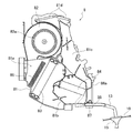
- FIG. 3A is a cross-sectional view illustrating the air conditioner unit according to the first embodiment.
- FIG. 3B is a rear perspective view illustrating the air conditioner unit according to the first embodiment. The configuration of the air conditioner unit according to the first embodiment will be described below with reference to FIGS. 3A and 3B.
- the air conditioner unit 8 of the first embodiment includes a unit housing 81, a fan unit 82, an evaporator 83, an expansion valve (not shown), and a PTC heater 84, as shown in FIG. 3A.
- reference numeral 85 denotes an air cleaner.
- the air conditioner unit 8 is attached to the center position in the vehicle width direction of the dash panel D and above the floor tunnel 10a formed in the floor panel 10, as shown in FIG. 3B.
- the unit housing 81 is a housing in which an air passage 81a is formed, and an air cleaner 85, an evaporator 83, an air mix door 81b, and a PTC heater 84 are sequentially arranged in the air passage 81a.
- a temperature-controlled air passage 81c Through which the temperature-controlled air whose temperature is adjusted by the evaporator 83 and the PTC heater 84 flows is formed.
- the temperature-controlled air passage 81c communicates with a plurality of air outlets formed in the instrument panel via a plurality of upper air blowing ports 81d formed in the upper part of the unit housing 81.
- an insertion portion 86 through which the high-voltage harness 13 is inserted is formed in the lower portion of the rear surface 86a facing the rear of the vehicle (see FIG. 3B).
- the fan unit 82 includes a fan motor (not shown) and a fan 82a that is rotationally driven by the fan motor, and feeds air into the unit housing 81. This sent air circulates in the air passage 81a.
- the evaporator 83 and the expansion valve cool the air flowing through the air passage 81a through which the refrigerant produced by the refrigeration cycle of the vehicle air conditioning system (not shown) flows.
- the PTC heater 84 supplies a current to a PTC (Positive Temperature Corfficient) element that generates heat when an electric current flows, and heats the air downstream of the evaporator 83.
- the heating wire of the PTC heater 84 is directly connected to the high voltage harness 13 extending from the battery pack 5 inside the unit housing 81.
- the high-voltage harness 13 is fixed with a clip 87 (see FIG. 3A) inside the insertion portion 86 in order to prevent vibration and displacement.
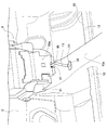
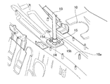
- FIG. 4 is a side view of an essential part showing an electric vehicle to which the harness routing structure of the first embodiment is applied.
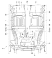
- FIG. 5 is a plan view of a principal part showing an electric vehicle to which the harness routing structure of the first embodiment is applied.
- the wiring structure of the high-voltage harness of Example 1 is demonstrated.
- the battery pack 5 is disposed in the underfloor space Y partitioned on the lower side of the floor panel 10.
- the lower side of the floor panel 10 is supported by a pair of side members 11, 11 extending in the vehicle front-rear direction.
- the floor panel 10 has a floor tunnel 10a extending in the vehicle front-rear direction at the center position in the vehicle width direction, and a plurality of cross members 12,... Extending in the vehicle width direction are formed on both sides of the floor tunnel 10a. Is provided.
- the battery pack 5 disposed in the underfloor space Y is fixedly supported via the bracket portion 58 with respect to the pair of side members 11, 11 or the cross member 12.
- the high-power connector terminal 57C provided at the front end of the battery pack 5 is set at the center position in the vehicle width direction.
- an air conditioner unit 8 is disposed in the vehicle compartment space R defined on the upper side of the floor panel 10 in front of the battery pack 5.
- the insertion portion 86 formed in the unit housing 81 of the air conditioner unit 8 is set at the center position in the vehicle width direction.
- the one end 13a of the high-voltage harness 13 is connected to the high-voltage connector terminal 57C, and the other end 13b of the high-voltage harness 13 is directly connected to the heating wire of the PTC heater 84 inside the unit housing 81. That is, the battery pack 5 and the PTC heater 84 are electrically connected via the high-voltage harness 13.
- the “high-power harness” is a harness that connects high-power components that are components whose line voltage is greater than 24 volts. Compared to a weak electrical harness that connects parts whose line voltage is less than 24 volts, the harness diameter is larger and the bending rigidity is higher.
- the high-power connector terminal 57C to which the one end 13a of the high-power harness 13 is connected corresponds to the lower floor harness connection position. Further, the position near the other end 13b of the high voltage harness 13 is fixed to the inside of the insertion portion 86 with a clip 87, and a position 87a (hereinafter referred to as “clip fixing position”) 87a fixed with the clip 87 is on the floor. Corresponds to the harness connection position.
- the intermediate portion of the high voltage harness 13 is routed along the vehicle front-rear direction and penetrates the harness through hole 14 formed in the floor panel 10.
- the harness through hole 14 is formed by cutting the floor panel 10 into a square shape in plan view, and a grommet 15 is provided on the inner side. Details of the grommet 15 will be described later.
- the position of the harness through hole 14 in the vehicle front-rear direction is set to a position between the high voltage connector terminal 57 ⁇ / b> C of the battery pack 5 and the clip fixing position 87 a of the air conditioner unit 8.
- it is set at a substantially central position between the high-power connector terminal 57C and the clip fixing position 87a.
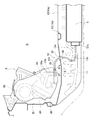
- the harness through-hole 14 is formed in the upper surface of the floor tunnel 10a, and the vehicle width direction position of this harness through-hole 14 is set to the vehicle width direction center position of the electric vehicle 1 as shown in FIG. That is, the distance from the pair of side members 11 and 11 to the harness through hole 14 is approximately the same.
- the harness through hole 14 is set at a position where it does not interfere with the cross member 12.
- the front cross member 12a provided on the most front side of the vehicle is set on the front side of the vehicle.
- the high-voltage harness 13 extends in the vehicle vertical direction in a portion that passes through the harness through hole 14, and the lower wiring portion 13 c from the harness through-hole 14 to the high-voltage connector terminal 57 ⁇ / b> C.
- the middle part of the vehicle is curved downward in the vehicle.
- an intermediate portion of the upper wiring portion 13d from the harness through hole 14 to the clip fixing position 87a is curved upward.
- the middle position of the lower wiring portion 13c is clipped to the lower surface of the floor tunnel 10a.
- FIG. 6A and 6B show the grommet of Example 1
- FIG. 6A is an external perspective view of the attached state
- FIG. 6B is a cross-sectional view of the attached state.
- the structure of the grommet of Example 1 is demonstrated.
- the grommet 15 has a pipe part 15a through which the high-voltage harness 13 passes, and a flange part 15b that protrudes from the periphery of the pipe part 15a and closes the harness through hole 14.
- the grommet 15 is formed of EPDM (ethylene propylene rubber) or the like that elastically deforms and allows the high-voltage harness 13 to bend and deform. In other words, the rigidity of the grommet 15 is set lower than that of the high-voltage harness 13.
- the tube portion 15a has a cylindrical shape with both ends open, and is in close contact with the outer peripheral surface of the high voltage harness 13.
- the intermediate part of the pipe part 15a is curved according to the wiring direction of the high-voltage harness 13 here.
- the flange portion 15b is formed with a fitting portion 15c fitted to the edge portion 14a of the harness through-hole 14 at the peripheral portion, and the fitting portion 15c is brought into close contact with the edge portion 14a, so that the grommet 15 becomes the floor panel 10. Fixed to. In addition, the flange portion 15b protrudes toward the lower side of the floor panel 10, and a plurality of concave portions 15d that are open to the vehicle interior space R are formed.
- a lower floor part is arranged below the floor panel, and an upper floor part is arranged on the upper side of the floor panel and on the front side of the vehicle with respect to the lower floor part, and these two parts are formed on the floor panel.
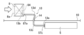
- FIGS. 7A to 7C are explanatory views schematically showing the positional relationship between the battery pack and the air conditioner unit when a frontal collision occurs
- FIG. 7A shows a state immediately after the collision
- FIG. 7B shows a state before the collision
- FIG. Indicates the late state of the collision.
- FIGS. 7A to 7C the front collision harness routing operation of the first embodiment will be described.
- a load (hereinafter referred to as a collision load) acting from the front of the vehicle to the rear of the vehicle acts on the electric vehicle 1. Since this collision load is input from the front end of the vehicle, immediately after the frontal collision occurs, an inertial force directed toward the front of the vehicle acts on the vehicle-mounted items including the air conditioner unit 8, the battery pack 5, the floor panel 10, and the like. . Since this inertial force acts on all the vehicles mounted, as shown in FIG. 7A, the relative positional relationship of the air conditioner unit 8, the high voltage harness 13, the harness through hole 14, and the battery pack 5 in the vehicle longitudinal direction changes. do not do.
- the drive motor 2 and the like disposed in the motor room M at the front of the vehicle move rearward of the vehicle due to the collision load and interfere with the air conditioner unit 8 disposed on the rear side of the dash panel D.
- the front surface 8a of the air conditioner unit 8 is pushed and starts moving toward the rear of the vehicle.
- the clip fixing position 87a by the clip 87 which fixed the high-voltage harness 13 to the unit housing 81 also moves to the vehicle rear.
- the high-voltage harness 13 that connects the PTC heater 84 in the air-conditioner unit 8 and the battery pack 5 has one end 13a fixed to the high-power connector terminal 57C of the battery pack 5 and the other end 13b fixed to the air-conditioner unit 8. It is fixed to the clip fixing position 87a. Further, since the high voltage harness 13 passes through the harness through hole 14 of the floor panel 10, movement in the vehicle front-rear direction is restricted at the position where the harness through hole 14 is formed.
- the harness through hole 14 is provided between the high-voltage connector terminal 57C and the clip fixing position 87a, that is, the harness through hole 14 is provided on the vehicle rear side with respect to the clip fixing position 87a.
- the clip fixing position 87a to which the high-voltage harness 13 is fixed also moves to the rear of the vehicle. Then, as the clip fixing position 87a moves backward in the vehicle, the clip fixing position 87a approaches the harness through hole 14.
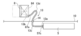
- both end portions are close to each other along the vehicle front-rear direction.
- the intermediate portion is not deformed in the bending direction, and the high-voltage harness 13 is not pulled or strongly abutted against the peripheral edge of the harness through hole 14.
- an inertial force toward the front of the vehicle acts on the battery pack 5 disposed in the underfloor space Y below the floor panel 10 in accordance with the occurrence of a frontal collision (see FIG. 7A).
- the battery pack 5 is fixed to the vehicle body member (the pair of side members 11, 11 and the cross member 12) here, the relative position with respect to the floor panel 10 hardly changes (see FIG. 7B).
- the relative positional relationship between the high-voltage connector terminal 57C to which the high-voltage harness 13 is connected and the harness through hole 14 does not change, and the lower wiring portion 13c of the high-voltage harness 13 has both ends positioned in the vehicle front-rear direction.
- the relationship does not change.
- the high-power harness 13 is not pulled or strongly abutted against the peripheral edge of the harness through-hole 14, and the load acting on the high-power harness 13 at the time of a vehicle front collision can be reduced.
- the high electric harness 13 since the high electric harness 13 has a larger harness diameter and higher bending rigidity than the weak electric harness, the high electric harness 13 is difficult to bend and is more likely to be subjected to a load.
- the harness through-hole 14 through which the high-voltage harness 13 passes as described above at a position between the high-voltage connector terminal 57C and the clip fixing position 87a the burden can be reduced even in the case of the high-voltage harness 13 that is difficult to bend. Can do.
- the harness through hole 14 is formed at a position where it does not interfere with the cross member 12. Therefore, the strength of the cross member 12 is not reduced by the harness through hole 14.
- a grommet 15 is provided inside the harness through hole 14. Since the grommet 15 is elastically deformed and allows the high-voltage harness 13 to bend and deform, when the high-voltage harness 13 is bent and deformed, the high-voltage harness 13 does not interfere with the deformation of the edge 14 a of the harness through-hole 14. Direct contact can be prevented. Thereby, the burden which acts on the high-voltage harness 13 at the time of a vehicle front collision can further be reduced.
- a plurality of recesses 15d opened to the vehicle interior space R are formed in the collar portion 15b. Therefore, the fixing strength of the high-voltage harness 13 due to the provision of the grommet 15 can be reduced, and the deformation followability when the high-voltage harness 13 is bent and deformed can be improved.
- FIG. 8 is a plan view schematically showing the positional relationship between the battery pack and the air conditioner unit.
- the high-power connector terminal 57C of the battery pack 5 disposed in the underfloor space Y is set at the center position in the vehicle width direction and disposed in the passenger compartment space R.
- the clip fixing position 87a of the air conditioner unit 8 is set at the center position in the vehicle width direction.
- the harness through-hole 14 formed in the floor panel 10 is set at the center position in the vehicle width direction. That is, the vehicle width direction position of the high-power connector terminal 57C, the vehicle width direction position of the harness through hole 14, and the vehicle width direction position of the clip fixing position 87a are the same.
- the high-voltage connector terminal 57C, the harness through hole 14, and the clip fixing position 87a are set at the center position in the vehicle width direction. Therefore, the distances L1 and L2 from the left and right side surfaces of the electric vehicle 1 (indicated by 1A and 1B in FIG. 8) to the high-voltage harness 13 are approximately the same.
- the high-voltage harness 13 is farthest from both the left and right side surfaces 1A and 1B of the electric vehicle 1, and the load acting on the high-voltage harness 13 at the time of a side collision can be further suppressed.
- a lower floor component (battery pack) 5 disposed below the floor panel 10 that partitions the passenger compartment space R and the underfloor space Y;
- An upper floor component (PTC heater) 84 that is disposed on the upper side of the floor panel 10 and on the vehicle front side with respect to the lower floor component 5;
- a harness (high-voltage harness) 13 for connecting the lower floor component 5 and the upper floor component 84;
- the on-floor harness connecting position (clip fixing position) 87a is set to a position between the front and rear direction of the vehicle.
- the floor lower harness connection position (high-power connector terminal) 57C, the harness through hole 14, and the floor upper harness connection position (clip fixing position) 87a are set to the center position in the vehicle width direction. .
- the floor panel 10 is supported by a cross member 12 extending in the vehicle width direction,
- the harness through hole 14 is set to a position where it does not interfere with the cross member 12. Thereby, the harness through-hole 14 can be formed without reducing the strength of the cross member 12.
- the harness through-hole 14 is provided with a grommet 15 capable of elastic deformation that allows bending deformation of the harness (high power harness) 13. This prevents the harness 13 from coming into direct contact with the edge 14a of the harness through-hole 14 without hindering the bending deformation of the harness 13, and further reduces the load acting on the harness 13 at the time of a vehicle front collision. it can.
- the lower floor component and the upper floor component are high voltage components (battery pack 5, PTC heater 84) whose line voltage is equal to or higher than a predetermined value
- the harness is configured as a high-power harness 13 that connects the high-power components.
- the lower part of the floor is a battery pack 5 serving as a power source for the motor 2 for traveling
- the on-floor part is configured as a heating wire heater (PTC heater) 84 provided in the air conditioner unit 8 disposed at the front of the vehicle.
- PTC heater heating wire heater
- Example 1 the under-floor part arranged on the lower side of the floor panel 10 was the battery pack 5, and the on-floor part arranged on the upper side of the floor panel 10 was the PTC heater 84 in the air conditioner unit 8.
- the present invention is not limited to this, and any type may be used as long as it is a component mounted on a vehicle.
- it may be an electric compressor or the like for flowing refrigerant through the drive motor inverter 3 or the air conditioner unit 8.
- it may be a weak electrical component having a relatively low line voltage.
- Example 1 although the harness through-hole 14 is obstruct
- the harness wiring structure of the electric vehicle of Example 1 showed the example applied to the electric vehicle 1 which a drive source drive
- the “strong electrical component” is a component having a line voltage greater than 24 volts, but the bolt value that is the boundary between the strong electrical component and the weak electrical component can be set to an arbitrary value.
Landscapes
- Engineering & Computer Science (AREA)
- Mechanical Engineering (AREA)
- Transportation (AREA)
- Power Engineering (AREA)
- Life Sciences & Earth Sciences (AREA)
- Sustainable Development (AREA)
- Sustainable Energy (AREA)
- Combustion & Propulsion (AREA)
- Chemical & Material Sciences (AREA)
- Architecture (AREA)
- Civil Engineering (AREA)
- Structural Engineering (AREA)
- Arrangement Or Mounting Of Propulsion Units For Vehicles (AREA)
- Installation Of Indoor Wiring (AREA)
Abstract
Priority Applications (7)
| Application Number | Priority Date | Filing Date | Title |
|---|---|---|---|
| JP2014536674A JPWO2014045754A1 (ja) | 2012-09-18 | 2013-08-08 | 電動車両のハーネス配索構造 |
| BR112015005688A BR112015005688A2 (pt) | 2012-09-18 | 2013-08-08 | estrutura de guia de chicote de fios para veículo elétrico |
| US14/411,921 US9187050B2 (en) | 2012-09-18 | 2013-08-08 | Harness routing structure for electric vehicle |
| RU2015114587A RU2015114587A (ru) | 2012-09-18 | 2013-08-08 | Конструкция прокладки жгута проводов для электрического транспортного средства |
| EP13838555.4A EP2899073A4 (fr) | 2012-09-18 | 2013-08-08 | Structure de guidage de fils couplés pour un véhicule électrique |
| MX2015003441A MX2015003441A (es) | 2012-09-18 | 2013-08-08 | Estructura de enrutamiento de arnes para vehiculo electrico. |
| CN201380048355.1A CN104640745A (zh) | 2012-09-18 | 2013-08-08 | 电动车辆的线束布线构造 |
Applications Claiming Priority (2)
| Application Number | Priority Date | Filing Date | Title |
|---|---|---|---|
| JP2012204194 | 2012-09-18 | ||
| JP2012-204194 | 2012-09-18 |
Publications (1)
| Publication Number | Publication Date |
|---|---|
| WO2014045754A1 true WO2014045754A1 (fr) | 2014-03-27 |
Family
ID=50341078
Family Applications (1)
| Application Number | Title | Priority Date | Filing Date |
|---|---|---|---|
| PCT/JP2013/071573 WO2014045754A1 (fr) | 2012-09-18 | 2013-08-08 | Structure de guidage de fils couplés pour un véhicule électrique |
Country Status (8)
| Country | Link |
|---|---|
| US (1) | US9187050B2 (fr) |
| EP (1) | EP2899073A4 (fr) |
| JP (1) | JPWO2014045754A1 (fr) |
| CN (1) | CN104640745A (fr) |
| BR (1) | BR112015005688A2 (fr) |
| MX (1) | MX2015003441A (fr) |
| RU (1) | RU2015114587A (fr) |
| WO (1) | WO2014045754A1 (fr) |
Cited By (9)
| Publication number | Priority date | Publication date | Assignee | Title |
|---|---|---|---|---|
| JP2016055843A (ja) * | 2014-09-12 | 2016-04-21 | 三菱自動車工業株式会社 | 車両のケーブル配置構造 |
| JP2019051817A (ja) * | 2017-09-15 | 2019-04-04 | 本田技研工業株式会社 | 車両 |
| JP2019062715A (ja) * | 2017-09-28 | 2019-04-18 | ダイハツ工業株式会社 | ハーネス配索構造 |
| CN110893757A (zh) * | 2018-09-12 | 2020-03-20 | 本田技研工业株式会社 | 车辆 |
| CN111954603A (zh) * | 2018-04-12 | 2020-11-17 | 日产自动车株式会社 | 车辆前方配置构造以及搭载有该车辆前方配置构造的车辆 |
| JP2021030780A (ja) * | 2019-08-20 | 2021-03-01 | マツダ株式会社 | ハーネス配設構造 |
| JP2021113007A (ja) * | 2020-01-21 | 2021-08-05 | 本田技研工業株式会社 | 車両のフロア構造 |
| DE102021105490A1 (de) | 2020-03-11 | 2021-09-16 | Suzuki Motor Corporation | Fahrzeugbatterie-halterung |
| US11383590B2 (en) | 2018-08-24 | 2022-07-12 | Toyota Jidosha Kabushiki Kaisha | Vehicle underfloor battery connector protector structure |
Families Citing this family (19)
| Publication number | Priority date | Publication date | Assignee | Title |
|---|---|---|---|---|
| US9187136B1 (en) * | 2014-08-01 | 2015-11-17 | Honda Motor Co., Ltd. | Structural pan for automotive body/frame |
| JP6436841B2 (ja) * | 2015-04-09 | 2018-12-12 | 株式会社クボタ | 電動作業車両 |
| DE102016203209B4 (de) * | 2016-02-29 | 2020-11-19 | Ford Global Technologies, Llc | Zumindest teilweise elektrisch betreibbares Kraftfahrzeug |
| DE102016111230A1 (de) | 2016-06-20 | 2017-12-21 | Dr. Ing. H.C. F. Porsche Aktiengesellschaft | Verformbare Schutzhülle zum Sichern mindestens einer Steuerungskomponente einer Batterie eines Fahrzeugs bei einem Aufprall |
| JP6609853B2 (ja) * | 2016-12-27 | 2019-11-27 | 本田技研工業株式会社 | 車両の空調ユニット取付部構造 |
| JP6802985B2 (ja) * | 2017-07-25 | 2020-12-23 | トヨタ紡織株式会社 | 乗物用内装材に対する電気部品の組付構造 |
| CN108621817A (zh) * | 2017-12-13 | 2018-10-09 | 蔚来汽车有限公司 | 充电座安装系统以及汽车 |
| JP6935756B2 (ja) * | 2018-01-30 | 2021-09-15 | トヨタ自動車株式会社 | 車両前部構造 |
| JP7059737B2 (ja) * | 2018-03-22 | 2022-04-26 | トヨタ自動車株式会社 | 電池パック |
| JP7056468B2 (ja) * | 2018-08-24 | 2022-04-19 | トヨタ自動車株式会社 | 車両床下構造 |
| US10889336B2 (en) | 2018-12-17 | 2021-01-12 | Ford Global Technologies, Llc | Polymeric vehicle floor |
| JP7110974B2 (ja) * | 2018-12-26 | 2022-08-02 | 株式会社オートネットワーク技術研究所 | 給電システム及び自動車 |
| JP7073299B2 (ja) * | 2019-05-07 | 2022-05-23 | 矢崎総業株式会社 | 車両用冷却システム |
| DE102019113701A1 (de) * | 2019-05-22 | 2020-11-26 | Bayerische Motoren Werke Aktiengesellschaft | Kraftfahrzeug mit einem elektrischen Antrieb und einer karosserieintegrierten Speicherzellenbaugruppe |
| KR20210030768A (ko) * | 2019-09-10 | 2021-03-18 | 두산인프라코어 주식회사 | 전기굴삭기의 전력공급장치 |
| JP7346364B2 (ja) * | 2020-06-29 | 2023-09-19 | 株式会社クボタ | 作業機 |
| JP7435313B2 (ja) * | 2020-07-01 | 2024-02-21 | マツダ株式会社 | 車両 |
| JP7343457B2 (ja) * | 2020-09-16 | 2023-09-12 | トヨタ自動車株式会社 | 電動車両 |
| CN112757885B (zh) * | 2021-01-25 | 2022-02-15 | 浙江零跑科技股份有限公司 | 一种电池包中部安装点与车身连接结构通用性的改进方法 |
Citations (5)
| Publication number | Priority date | Publication date | Assignee | Title |
|---|---|---|---|---|
| WO2010098271A1 (fr) * | 2009-02-24 | 2010-09-02 | 日産自動車株式会社 | Structure d'installation de batteries |
| JP2011025863A (ja) | 2009-07-28 | 2011-02-10 | Toyota Motor Corp | 電気自動車 |
| JP2011063147A (ja) * | 2009-09-18 | 2011-03-31 | Suzuki Motor Corp | 車両の高電圧ケーブルの配索構造 |
| JP2011068187A (ja) * | 2009-09-24 | 2011-04-07 | Suzuki Motor Corp | 車両の高電圧ケーブルの配策構造 |
| JP2011126451A (ja) * | 2009-12-18 | 2011-06-30 | Nissan Motor Co Ltd | 電動車両用バッテリのコネクタ構造 |
Family Cites Families (20)
| Publication number | Priority date | Publication date | Assignee | Title |
|---|---|---|---|---|
| JPH06199183A (ja) | 1992-12-28 | 1994-07-19 | Honda Motor Co Ltd | 電気自動車のコンソールボックス |
| US6598691B2 (en) * | 1997-12-18 | 2003-07-29 | Honda Giken Kogyo Kabushiki Kaisha | Electric vehicle |
| JP2000247261A (ja) * | 1999-02-26 | 2000-09-12 | Nissan Motor Co Ltd | 車体フロア構造 |
| JP3909763B2 (ja) * | 2002-11-20 | 2007-04-25 | 株式会社オートネットワーク技術研究所 | シールド機能を備えた車両用導電路 |
| JP2004224156A (ja) * | 2003-01-22 | 2004-08-12 | Honda Motor Co Ltd | 車両用電力ケーブル保持構造 |
| JP4415910B2 (ja) * | 2005-07-12 | 2010-02-17 | トヨタ自動車株式会社 | ハイブリッド車両の構造 |
| US7561445B2 (en) * | 2005-11-10 | 2009-07-14 | Nissan Motor Co., Ltd. | Harness routing structure for vehicle |
| JP4386131B2 (ja) * | 2007-12-05 | 2009-12-16 | 三菱自動車工業株式会社 | 電気自動車 |
| JP5386126B2 (ja) * | 2008-08-19 | 2014-01-15 | 矢崎総業株式会社 | ワイヤハーネス |
| JP5269519B2 (ja) * | 2008-08-19 | 2013-08-21 | 矢崎総業株式会社 | ワイヤハーネス製造方法 |
| JP5047143B2 (ja) * | 2008-12-18 | 2012-10-10 | 本田技研工業株式会社 | 車両の配線構造 |
| JP5572372B2 (ja) * | 2009-12-07 | 2014-08-13 | 矢崎総業株式会社 | ワイヤハーネスの配索構造及びワイヤハーネス |
| JP5446953B2 (ja) | 2010-02-08 | 2014-03-19 | 住友電装株式会社 | グロメット |
| JP2011230530A (ja) * | 2010-04-23 | 2011-11-17 | Mitsubishi Motors Corp | 電動車両 |
| JP2012039689A (ja) | 2010-08-04 | 2012-02-23 | Mitsubishi Motors Corp | 平滑コンデンサの電荷開放装置 |
| JP5249365B2 (ja) * | 2011-01-26 | 2013-07-31 | 三菱電機株式会社 | 電力変換装置 |
| JP5561206B2 (ja) | 2011-02-25 | 2014-07-30 | 株式会社デンソー | バッテリの充電制御装置 |
| JP2012183903A (ja) * | 2011-03-04 | 2012-09-27 | Suzuki Motor Corp | 車両の高圧ケーブル配索構造 |
| JP5810615B2 (ja) * | 2011-05-09 | 2015-11-11 | スズキ株式会社 | 自動車電装部品用保護構造 |
| US8831808B2 (en) * | 2012-02-24 | 2014-09-09 | Ford Global Technologies, Llc | Controlled shutdown of an electric vehicle |
-
2013
- 2013-08-08 WO PCT/JP2013/071573 patent/WO2014045754A1/fr active Application Filing
- 2013-08-08 CN CN201380048355.1A patent/CN104640745A/zh active Pending
- 2013-08-08 BR BR112015005688A patent/BR112015005688A2/pt not_active IP Right Cessation
- 2013-08-08 RU RU2015114587A patent/RU2015114587A/ru unknown
- 2013-08-08 MX MX2015003441A patent/MX2015003441A/es unknown
- 2013-08-08 EP EP13838555.4A patent/EP2899073A4/fr not_active Withdrawn
- 2013-08-08 US US14/411,921 patent/US9187050B2/en not_active Expired - Fee Related
- 2013-08-08 JP JP2014536674A patent/JPWO2014045754A1/ja active Pending
Patent Citations (5)
| Publication number | Priority date | Publication date | Assignee | Title |
|---|---|---|---|---|
| WO2010098271A1 (fr) * | 2009-02-24 | 2010-09-02 | 日産自動車株式会社 | Structure d'installation de batteries |
| JP2011025863A (ja) | 2009-07-28 | 2011-02-10 | Toyota Motor Corp | 電気自動車 |
| JP2011063147A (ja) * | 2009-09-18 | 2011-03-31 | Suzuki Motor Corp | 車両の高電圧ケーブルの配索構造 |
| JP2011068187A (ja) * | 2009-09-24 | 2011-04-07 | Suzuki Motor Corp | 車両の高電圧ケーブルの配策構造 |
| JP2011126451A (ja) * | 2009-12-18 | 2011-06-30 | Nissan Motor Co Ltd | 電動車両用バッテリのコネクタ構造 |
Non-Patent Citations (1)
| Title |
|---|
| See also references of EP2899073A4 |
Cited By (17)
| Publication number | Priority date | Publication date | Assignee | Title |
|---|---|---|---|---|
| JP2016055843A (ja) * | 2014-09-12 | 2016-04-21 | 三菱自動車工業株式会社 | 車両のケーブル配置構造 |
| JP2019051817A (ja) * | 2017-09-15 | 2019-04-04 | 本田技研工業株式会社 | 車両 |
| JP2019062715A (ja) * | 2017-09-28 | 2019-04-18 | ダイハツ工業株式会社 | ハーネス配索構造 |
| US20210107331A1 (en) * | 2018-04-12 | 2021-04-15 | Nissan Motor Co., Ltd. | Vehicle front-arrangement structure and vehicle equipped with vehicle front-arrangement structure |
| JP7055196B2 (ja) | 2018-04-12 | 2022-04-15 | 日産自動車株式会社 | 車両前方配置構造及び該車両前方配置構造を搭載した車両 |
| JPWO2019197857A1 (ja) * | 2018-04-12 | 2021-02-12 | 日産自動車株式会社 | 車両前方配置構造及び該車両前方配置構造を搭載した車両 |
| US11945281B2 (en) | 2018-04-12 | 2024-04-02 | Nissan Motor Co., Ltd. | Vehicle front-arrangement structure and vehicle equipped with vehicle front-arrangement structure |
| EP3778277A4 (fr) * | 2018-04-12 | 2021-03-03 | Nissan Motor Co., Ltd. | Structure d'agencement avant de véhicule et véhicule équipé de la structure d'agencement avant de véhicule |
| CN111954603A (zh) * | 2018-04-12 | 2020-11-17 | 日产自动车株式会社 | 车辆前方配置构造以及搭载有该车辆前方配置构造的车辆 |
| US11383590B2 (en) | 2018-08-24 | 2022-07-12 | Toyota Jidosha Kabushiki Kaisha | Vehicle underfloor battery connector protector structure |
| CN110893757A (zh) * | 2018-09-12 | 2020-03-20 | 本田技研工业株式会社 | 车辆 |
| CN110893757B (zh) * | 2018-09-12 | 2023-03-03 | 本田技研工业株式会社 | 车辆 |
| JP7345730B2 (ja) | 2019-08-20 | 2023-09-19 | マツダ株式会社 | ハーネス配設構造 |
| JP2021030780A (ja) * | 2019-08-20 | 2021-03-01 | マツダ株式会社 | ハーネス配設構造 |
| JP7008734B2 (ja) | 2020-01-21 | 2022-01-25 | 本田技研工業株式会社 | 車両のフロア構造 |
| JP2021113007A (ja) * | 2020-01-21 | 2021-08-05 | 本田技研工業株式会社 | 車両のフロア構造 |
| DE102021105490A1 (de) | 2020-03-11 | 2021-09-16 | Suzuki Motor Corporation | Fahrzeugbatterie-halterung |
Also Published As
| Publication number | Publication date |
|---|---|
| MX2015003441A (es) | 2015-06-22 |
| US9187050B2 (en) | 2015-11-17 |
| EP2899073A1 (fr) | 2015-07-29 |
| JPWO2014045754A1 (ja) | 2016-08-18 |
| CN104640745A (zh) | 2015-05-20 |
| EP2899073A4 (fr) | 2015-11-04 |
| BR112015005688A2 (pt) | 2017-07-04 |
| RU2015114587A (ru) | 2016-11-10 |
| US20150144414A1 (en) | 2015-05-28 |
Similar Documents
| Publication | Publication Date | Title |
|---|---|---|
| WO2014045754A1 (fr) | Structure de guidage de fils couplés pour un véhicule électrique | |
| JP5516084B2 (ja) | 車載システム回路の充電器搭載構造 | |
| JP5018837B2 (ja) | 電気自動車の搭載構造 | |
| JP5807476B2 (ja) | 電気自動車のバッテリパック車体支持構造 | |
| EP2419291B1 (fr) | Agencement de montage de composants de véhicule | |
| JP5446537B2 (ja) | 電気自動車の搭載構造 | |
| JP4924671B2 (ja) | 電気自動車の搭載構造 | |
| JP6706507B2 (ja) | 車両 | |
| US8662222B1 (en) | Motor room of electric vehicle | |
| JP2011006050A (ja) | 電気自動車の電気部品搭載構造 | |
| JP4968292B2 (ja) | 電気自動車の搭載構造 | |
| US11912133B2 (en) | Vehicle drive unit | |
| US20200070755A1 (en) | Electric device installation structure in vehicle | |
| JP7290589B2 (ja) | 電力制御ユニット | |
| JP6431827B2 (ja) | 車両 | |
| JP2009544512A (ja) | 自動車 | |
| CN111661166B (zh) | 车辆前部结构 | |
| JP5880723B2 (ja) | パーキングブレーキケーブルの配索構造 | |
| WO2020183750A1 (fr) | Système de câblage de véhicule | |
| JP2017077861A (ja) | 電力変換器の車載構造 | |
| JP2023136720A (ja) | 電動車両の駆動装置 |
Legal Events
| Date | Code | Title | Description |
|---|---|---|---|
| 121 | Ep: the epo has been informed by wipo that ep was designated in this application |
Ref document number: 13838555 Country of ref document: EP Kind code of ref document: A1 |
|
| ENP | Entry into the national phase |
Ref document number: 2014536674 Country of ref document: JP Kind code of ref document: A |
|
| WWE | Wipo information: entry into national phase |
Ref document number: 14411921 Country of ref document: US |
|
| NENP | Non-entry into the national phase |
Ref country code: DE |
|
| WWE | Wipo information: entry into national phase |
Ref document number: MX/A/2015/003441 Country of ref document: MX |
|
| REEP | Request for entry into the european phase |
Ref document number: 2013838555 Country of ref document: EP |
|
| REG | Reference to national code |
Ref country code: BR Ref legal event code: B01A Ref document number: 112015005688 Country of ref document: BR |
|
| WWE | Wipo information: entry into national phase |
Ref document number: 2013838555 Country of ref document: EP |
|
| ENP | Entry into the national phase |
Ref document number: 2015114587 Country of ref document: RU Kind code of ref document: A |
|
| ENP | Entry into the national phase |
Ref document number: 112015005688 Country of ref document: BR Kind code of ref document: A2 Effective date: 20150313 |