WO2014025063A1 - 重ね合せ溶接部材、自動車用部品、重ね合せ部の溶接方法、及び、重ね合せ溶接部材の製造方法 - Google Patents
重ね合せ溶接部材、自動車用部品、重ね合せ部の溶接方法、及び、重ね合せ溶接部材の製造方法 Download PDFInfo
- Publication number
- WO2014025063A1 WO2014025063A1 PCT/JP2013/071841 JP2013071841W WO2014025063A1 WO 2014025063 A1 WO2014025063 A1 WO 2014025063A1 JP 2013071841 W JP2013071841 W JP 2013071841W WO 2014025063 A1 WO2014025063 A1 WO 2014025063A1
- Authority
- WO
- WIPO (PCT)
- Prior art keywords
- energization
- nugget
- cyc
- welding
- steel plate
- Prior art date
- Legal status (The legal status is an assumption and is not a legal conclusion. Google has not performed a legal analysis and makes no representation as to the accuracy of the status listed.)
- Ceased
Links
Images


Classifications
-
- B—PERFORMING OPERATIONS; TRANSPORTING
- B23—MACHINE TOOLS; METAL-WORKING NOT OTHERWISE PROVIDED FOR
- B23K—SOLDERING OR UNSOLDERING; WELDING; CLADDING OR PLATING BY SOLDERING OR WELDING; CUTTING BY APPLYING HEAT LOCALLY, e.g. FLAME CUTTING; WORKING BY LASER BEAM
- B23K11/00—Resistance welding; Severing by resistance heating
- B23K11/16—Resistance welding; Severing by resistance heating taking account of the properties of the material to be welded
-
- B—PERFORMING OPERATIONS; TRANSPORTING
- B23—MACHINE TOOLS; METAL-WORKING NOT OTHERWISE PROVIDED FOR
- B23K—SOLDERING OR UNSOLDERING; WELDING; CLADDING OR PLATING BY SOLDERING OR WELDING; CUTTING BY APPLYING HEAT LOCALLY, e.g. FLAME CUTTING; WORKING BY LASER BEAM
- B23K11/00—Resistance welding; Severing by resistance heating
- B23K11/10—Spot welding; Stitch welding
- B23K11/11—Spot welding
- B23K11/115—Spot welding by means of two electrodes placed opposite one another on both sides of the welded parts
-
- B—PERFORMING OPERATIONS; TRANSPORTING
- B23—MACHINE TOOLS; METAL-WORKING NOT OTHERWISE PROVIDED FOR
- B23K—SOLDERING OR UNSOLDERING; WELDING; CLADDING OR PLATING BY SOLDERING OR WELDING; CUTTING BY APPLYING HEAT LOCALLY, e.g. FLAME CUTTING; WORKING BY LASER BEAM
- B23K31/00—Processes relevant to this subclass, specially adapted for particular articles or purposes, but not covered by any single one of main groups B23K1/00 - B23K28/00
- B23K31/12—Processes relevant to this subclass, specially adapted for particular articles or purposes, but not covered by any single one of main groups B23K1/00 - B23K28/00 relating to investigating the properties, e.g. the weldability, of materials
-
- C—CHEMISTRY; METALLURGY
- C21—METALLURGY OF IRON
- C21D—MODIFYING THE PHYSICAL STRUCTURE OF FERROUS METALS; GENERAL DEVICES FOR HEAT TREATMENT OF FERROUS OR NON-FERROUS METALS OR ALLOYS; MAKING METAL MALLEABLE, e.g. BY DECARBURISATION OR TEMPERING
- C21D6/00—Heat treatment of ferrous alloys
-
- C—CHEMISTRY; METALLURGY
- C21—METALLURGY OF IRON
- C21D—MODIFYING THE PHYSICAL STRUCTURE OF FERROUS METALS; GENERAL DEVICES FOR HEAT TREATMENT OF FERROUS OR NON-FERROUS METALS OR ALLOYS; MAKING METAL MALLEABLE, e.g. BY DECARBURISATION OR TEMPERING
- C21D9/00—Heat treatment, e.g. annealing, hardening, quenching or tempering, adapted for particular articles; Furnaces therefor
- C21D9/0068—Heat treatment, e.g. annealing, hardening, quenching or tempering, adapted for particular articles; Furnaces therefor for particular articles not mentioned below
-
- C—CHEMISTRY; METALLURGY
- C21—METALLURGY OF IRON
- C21D—MODIFYING THE PHYSICAL STRUCTURE OF FERROUS METALS; GENERAL DEVICES FOR HEAT TREATMENT OF FERROUS OR NON-FERROUS METALS OR ALLOYS; MAKING METAL MALLEABLE, e.g. BY DECARBURISATION OR TEMPERING
- C21D9/00—Heat treatment, e.g. annealing, hardening, quenching or tempering, adapted for particular articles; Furnaces therefor
- C21D9/50—Heat treatment, e.g. annealing, hardening, quenching or tempering, adapted for particular articles; Furnaces therefor for welded joints
-
- C—CHEMISTRY; METALLURGY
- C22—METALLURGY; FERROUS OR NON-FERROUS ALLOYS; TREATMENT OF ALLOYS OR NON-FERROUS METALS
- C22C—ALLOYS
- C22C38/00—Ferrous alloys, e.g. steel alloys
-
- C—CHEMISTRY; METALLURGY
- C22—METALLURGY; FERROUS OR NON-FERROUS ALLOYS; TREATMENT OF ALLOYS OR NON-FERROUS METALS
- C22C—ALLOYS
- C22C9/00—Alloys based on copper
-
- B—PERFORMING OPERATIONS; TRANSPORTING
- B23—MACHINE TOOLS; METAL-WORKING NOT OTHERWISE PROVIDED FOR
- B23K—SOLDERING OR UNSOLDERING; WELDING; CLADDING OR PLATING BY SOLDERING OR WELDING; CUTTING BY APPLYING HEAT LOCALLY, e.g. FLAME CUTTING; WORKING BY LASER BEAM
- B23K2101/00—Articles made by soldering, welding or cutting
- B23K2101/006—Vehicles
-
- B—PERFORMING OPERATIONS; TRANSPORTING
- B23—MACHINE TOOLS; METAL-WORKING NOT OTHERWISE PROVIDED FOR
- B23K—SOLDERING OR UNSOLDERING; WELDING; CLADDING OR PLATING BY SOLDERING OR WELDING; CUTTING BY APPLYING HEAT LOCALLY, e.g. FLAME CUTTING; WORKING BY LASER BEAM
- B23K2101/00—Articles made by soldering, welding or cutting
- B23K2101/18—Sheet panels
-
- B—PERFORMING OPERATIONS; TRANSPORTING
- B23—MACHINE TOOLS; METAL-WORKING NOT OTHERWISE PROVIDED FOR
- B23K—SOLDERING OR UNSOLDERING; WELDING; CLADDING OR PLATING BY SOLDERING OR WELDING; CUTTING BY APPLYING HEAT LOCALLY, e.g. FLAME CUTTING; WORKING BY LASER BEAM
- B23K2103/00—Materials to be soldered, welded or cut
- B23K2103/02—Iron or ferrous alloys
- B23K2103/04—Steel or steel alloys
-
- C—CHEMISTRY; METALLURGY
- C21—METALLURGY OF IRON
- C21D—MODIFYING THE PHYSICAL STRUCTURE OF FERROUS METALS; GENERAL DEVICES FOR HEAT TREATMENT OF FERROUS OR NON-FERROUS METALS OR ALLOYS; MAKING METAL MALLEABLE, e.g. BY DECARBURISATION OR TEMPERING
- C21D2211/00—Microstructure comprising significant phases
- C21D2211/008—Martensite
Definitions
- the present invention relates to a lap weld member in which lap portions of a plurality of steel plate members are joined by spot welds, an automotive part having the lap weld member, a method of welding the lap portion, and the manufacture of the lap weld member Regarding the method.
- hot stamp materials having a tensile strength of 1500 MPa or more have been put into practical use.
- the hot stamp material here refers to press working in a state where the steel plate is heated to about 900 ° C. and softened, and at the same time, strengthening by quenching due to the cooling effect (contact cooling) accompanying the contact with the mold, The above-described tensile strength of 1500 MPa class and good dimensional accuracy are realized.
- resistance spot welding in which two or more steel plate members formed from steel plates are superposed and energized while being pressed with an electrode is frequently used.
- this resistance spot welding the melted and solidified portion of an ellipsoid, that is, the nugget is formed in the overlapped portion by energization heating, whereby a plurality of steel plate members can be joined.
- FIG. 1 is a diagram conceptually illustrating the hardness distribution of the spot welded portion 10 when the conventional energization condition is applied to two TRIP (TRansformation Induced Plasticity) materials S11 and S12. More specifically, FIG. 1A is a cross-sectional view conceptually showing the vicinity of the spot welded portion 10 with the thickness direction of the TRIP materials S11 and S12 (that is, the pressing direction by the electrodes) as the vertical direction on the paper surface. is there. In the following description of the present specification, a case where two superimposed members are viewed in the same cross section as in FIG. 1A is referred to as a “spot weld cross-sectional view”. There is. FIG.
- the spot welded portion 10 includes a nugget 12 and a HAZ 14, and the HAZ 14 has a HAZ hardened portion 14H adjacent to the nugget 12 and a HAZ softened portion 14T formed around the HAZ hardened portion 14H. And have. Further, the HAZ softest part 14L exists at the inner peripheral edge of the HAZ softened part 14T.
- the quality of spot welds is often evaluated by the tensile shear strength and the cross tensile strength (joint strength in the peeling direction), and it is known that the tensile shear strength increases as the base metal strength increases. ing.
- the peel strength represented by the cross tensile strength tends to decrease as the strength of the base material increases.
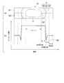
- FIG. 2A the outline of the cross tension test based on JISZ3137 (1999) for measuring cross tensile strength is demonstrated.
- the cross tension test as shown in FIG. 2A, two test pieces S21 and S22 made of a steel plate are arranged orthogonally to form a spot weld 10 having a nugget 12 by resistance spot welding and joined. Thereafter, the test pieces S21 and S22 are pulled in the direction in which they are peeled from each other, and the peel strength until the spot welded portion 10 breaks is measured.
- the fracture form by the cross tension test is (A) interfacial fracture breaking at the interface between the plates in the nugget; (B) As shown in FIG. 2B, a partial plug break that breaks in the plate thickness direction after a crack has developed inside the nugget 12 (inward from the nugget end 12E); (C) As shown in FIG. 2C, the nugget 12 does not break, and the outer peripheral portion of the nugget 12 breaks in the plate thickness direction; are categorized.
- FIG. 2D is a diagram illustrating an example of the correlation between the base material tensile strength and the cross tensile strength.
- “black circles” indicate plug breaks and “open circles” indicate partial plug breaks.
- the cross tensile strength is about 9 kN in the 1500 MPa class hot stamping material (the steel sheet member after hot stamping the steel sheet for hot stamping having a tensile strength of 1500 MPa by hot stamping), and the 1800 MPa class.
- a hot stamp material a steel plate member after hot stamping a hot stamping steel plate having a tensile strength of 1800 MPa by hot stamping
- it is about 4 kN.
- the cross tensile strength of the high-strength steel plate of 980 MPa or less is about 8 to 14 kN. That is, a hot stamp material of 1500 MPa class or higher has a significantly reduced cross tensile strength as compared with a high strength steel sheet of 980 MPa class or lower.
- the rupture form by the cross tensile test is mainly a plug rupture that breaks outside the nugget 12 in a high-strength steel sheet of 980 MPa or less, whereas a partial plug is used in a 1500 MPa class hot stamp material or a 1800 MPa class hot stamp material. It is mainly broken. This indicates that in the hot stamp material of 1500 MPa class or higher, the nugget is easily cracked due to the low toughness of the nugget.
- the main cause of the decrease in peel strength in spot welding of high-strength steel sheets is that the toughness decreases as the nugget hardness increases, and breakage within the nugget (partial plug breakage) is likely to occur. it is conceivable that.
- the nugget diameter when the nugget diameter is increased, the fracture form is more likely to be a plug fracture than the partial plug fracture, and the strength of the spot welded portion is increased. Therefore, for example, increasing the nugget diameter is effective in improving the peel strength of the spot welded portion of the high-tensile steel plate.
- a technique for improving the strength of a lap weld member by resistance spot welding is desired with the conventional nugget diameter.
- a post-energization method is disclosed in which a nugget is formed by main energization, and once energized, the energization is performed again (see, for example, Non-Patent Document 1).
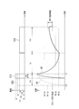
- the post-energization method for example, as shown in FIG. 3, in a state where a predetermined pressure is applied by an electrode in resistance spot welding, (A) Forming a nugget by conducting the first energization (main energization) under conventional normal conditions, (B) Cool until martensite is formed around the nugget with a predetermined downtime, (C) The martensite is tempered by the second energization (post energization).
- the heat affected zone (Heat-Affected Zone, hereinafter referred to as HAZ) of the nugget and the spot welded portion is tempered to improve toughness, and the HAZ is softened to deform. Since it becomes easy to do, since the stress at the time of peeling in a nugget edge part area
- martensite is generated by rapidly cooling until the molten metal passes through the Ms point and falls below the Mf point.
- the martensite produced here has an appropriate temperature range in which tempering is possible by adjusting the amount of heat input by controlling the current conditions for post-energization (ie, about 550 ° C. to 600 ° C. as shown in FIG. 3). Tempered martensite by being heated to a temperature not lower than C ° C and not higher than Ac1 point) and cooled after completion of post-energization.
- FIG. 4 shows a spot weld 10 formed by superposing test pieces S31 and S32 which are DP (Dual Phase) materials or TRIP materials based on the normal conditions in the conventional resistance spot welding shown in FIG. It is a figure which illustrates notionally the hardness distribution of the spot weld part 10 after having performed. More specifically, FIG. 4A is a cross-sectional view of a spot weld, and FIG. 4B conceptually shows the distribution of Vickers hardness corresponding to the position of FIG. It is a graph to show.
- the spot welded portion 10 is first formed by main energization.
- the spot welded portion 10 includes the nugget 12 and the HAZ 14, and the HAZ 14 is surrounded by the HAZ cured portion 14H and the HAZ cured portion 14H adjacent to the nugget 12.
- the HAZ softened portion 14T is formed. Further, the HAZ softest part 14L exists at the inner peripheral edge of the HAZ softened part 14T.
- the nugget 12 and the HAZ cured portion 14H are tempered to reduce the hardness of the nugget 12 and the HAZ cured portion 14H.
- the hard portion 14P locally remains in the HAZ hardened portion 14H, the hard portion of the HAZ 14 does not deform at the time of peeling, and the deformation concentrates in the vicinity of the nugget end 12E. It will not improve enough.
- FIG. 5 shows spot welding in the case where a spot welded portion 10 is formed by applying resistance spot welding according to conventional normal conditions to the test pieces S41 and S42 of the hot stamp material, and the spot welded portion 10 is energized afterwards.
- FIG. 6 is a diagram conceptually illustrating a change in HAZ 14 in a unit 10. More specifically, FIG. 5A is a cross-sectional view of the spot welded portion including the nugget 12 formed by single energization with respect to the test pieces S41 and S42, and FIG. 5B is a cross-sectional view of FIG. It is a graph which shows notionally distribution of Vickers hardness which made a position correspond to a).
- FIG. 5C is a cross-sectional view of the spot welded portion including the nugget 12 after the post-energization
- FIG. 5D is a view of the Vickers hardness corresponding to the position of FIG. 5C. It is a graph which shows distribution conceptually. Note that the two-dot chain line shown in FIG. 5D shows the distribution of Vickers hardness after the main energization and before the post-energization.
- tempering is promoted over a wide range of the nugget 12 and the HAZ hardened portion 14H as shown in FIG. 5 (d). Tempering with the softened portion 14L cannot be sufficiently performed, and a portion 14P having locally high Vickers hardness remains. That is, since the effect of improving toughness by tempering cannot be obtained sufficiently, it is not easy to ensure sufficient peel strength of the spot welded part 10.
- the conventional post-energization method is not practical because it is not easy to sufficiently obtain the effect of improving the toughness of the spot welded part, and there is a problem that the welding time becomes long.
- various techniques have been disclosed.
- Patent Document 1 discloses an invention in which post-energization conditions are determined according to a plate set by numerical calculation.
- Patent Document 2 discloses an invention in which post-energization is performed for a short time and a high current condition at least once to effectively generate heat at a location that becomes a fracture starting point, and shorten the welding time. It is said that it can have a wide range of appropriate conditions.
- Patent Document 3 discloses an invention that increases the breaking strength of the joint portion by enlarging the width of the HAZ softened portion around the nugget by re-energizing and refining the structure while maintaining the hardness of the nugget. Has been.
- Patent Document 4 a simple two-stage energization type spot welding consisting of a combination of main energization and temper energization generates a maximum point in the hardness of the HAZ part while maintaining the hardness of the nugget, thereby increasing the high tension.
- An invention relating to spot welding capable of ensuring excellent tensile strength for a steel sheet is disclosed.
- Japanese Unexamined Patent Publication No. 2002-103054 Japanese Unexamined Patent Publication No. 2010-115706 Japanese Unexamined Patent Publication No. 2012-187617 Japanese Unexamined Patent Publication No. 2008-229720
- Patent Document 1 According to the technique disclosed in Patent Document 1, it is said that the conditions of post-energization can be optimized for the purpose of improving the peel strength and fatigue strength of spot welds. However, since the residual stress is utilized, the effect is limited.
- Patent Document 2 it is said that by optimizing post-energization after welding, the hardened portion of the nugget and HAZ that are the starting points of fracture can be softened and the toughness can be improved.
- the state of softening is not specifically shown and the cross tensile strength is supposed to be improved, the mechanism is unclear and the peel strength could not be improved sufficiently.
- Patent Literature 3 although it is said that the breaking strength can be improved by widening the HAZ part, as described later, for the relaxation of strain concentration, the HAZ rather than the width of the HAZ part. Since the softening position is important, strain concentration at the end of the nugget may not be sufficiently relaxed.
- Patent Document 4 it is said that excellent tensile strength can be obtained by returning the distribution of the hardened portion of the HAZ part, but the joint strength can be improved by dispersing the strain concentration on the HAZ part. Since this is a technique for achieving this, it may be difficult to obtain the effect when the nugget breaks.
- the techniques disclosed in Patent Document 3 and Cited Document 4 are techniques in which the effect cannot be obtained with a hot stamp material of 1500 MPa class or higher as the object of the present invention.
- the present invention has been made in view of such circumstances, and a lap weld member capable of improving the peel strength at a spot welded portion, an automotive part having the lap weld member, and welding of the overlap portion. It is an object of the present invention to provide a method and a method for manufacturing a lap weld member.
- a first aspect of the present invention is a lap weld member in which overlapping portions of a plurality of steel plate members are joined by spot welds, and at least one of the plurality of steel plate members includes martensite.
- a lap weld member is a lap weld member.
- a second aspect of the present invention is a lap weld member in which overlapping portions of a plurality of steel plate members are joined by spot welds, wherein at least one of the plurality of steel plate members is martensite.
- the spot weld has a nugget formed by resistance spot welding, a heat affected zone formed around the nugget, and a softened portion having the lowest Vickers hardness in the heat affected zone.
- the distance from the melt boundary portion of the nugget to the softest portion is D (mm), and if the number of the steel plate members having the highest tensile strength among the plurality of steel plate members is singular, the thickness is t (mm).
- the plurality of steel plate members may include a hot stamp material.
- a third aspect of the present invention is an automotive part including the lap weld member according to any one of (1) to (3) above.
- a nugget, a heat-affected zone formed around the nugget, and a lowest Vickers hardness in the heat-affected zone are formed on the overlapping portion of the plurality of steel plate members.
- a resistance spot welding step of forming a spot welded portion having a softened portion by resistance spot welding; and a tempered martensite between the center portion of the nugget and the softest portion, and its Vickers hardness is And a tempering step for forming a tempered region that is 120% or less when the Vickers hardness of the softest part is 100%.
- the energization time of the resistance spot welding is T (seconds), and the tensile strength is the highest among the plurality of steel plate members. If there is a single steel plate member with a high thickness, the thickness is set to t (mm). On the other hand, if there are a plurality of steel plate members with the highest tensile strength, the thickness of the steel plate member with the smallest thickness among them is set.
- t (mm) is set, and the time of one cycle of the resistance spot welding energization is cyc (seconds), the energization may be performed so as to satisfy the following expression (2).
- a welding current I 0 (kA) equal to or smaller than the generation current of dust is applied to the overlapped portion;
- the preheating current I (kA) and the welding current I 0 (kA) are expressed by the following formula (5): May be satisfied.
- Formula (8) In the welding method of the overlapped portion described in the above (5), in the resistance spot welding step, the distance from the fusion boundary portion of the nugget to the softest portion is D (mm).
- the plate thickness is t (mm)
- the tempering step is performed by post-energization. It may be a post-energization step for forming the return region. D ⁇ t 0.2 (6) Equation (9)
- the energization time of the resistance spot welding is T (seconds).
- the energization may be performed so as to satisfy the following expression (7). 5t ⁇ cyc ⁇ T ⁇ (5t + 4) ⁇ cyc (7) Formula (10)
- the energization time T 1 ( Second) satisfy the following formula (8), and preheating for energizing the overlapping portion with a preheating current I (kA)
- the energization time is T 2 (seconds) and the time of one energization cycle is cyc (seconds)
- the following equation (9) is satisfied.
- a welding current I 0 (kA) equal to or less than the generated current is supplied to the overlapping portion; the preheating current I (kA) and the welding current I 0 (kA) may satisfy the following expression (10).
- Formula (11) According to a fifth aspect of the present invention, there are provided a nugget, a heat-affected zone formed around the nugget, and a Vickers in the heat-affected zone.
- the energization may be performed so as to satisfy the following expression (12). 5t ⁇ cyc ⁇ T ⁇ (5t + 4) ⁇ cyc (12) Formula (13)
- the energization time T 1 ( Second), time cyc (second) of one energization cycle, and the plate thickness t (mm) satisfy the following equation (13), and preheating current I (kA) is supplied to the overlapped portion.
- the energization time is T 2 (seconds) and the energization time of 1 cycle is cyc (seconds).
- the following welding current I 0 (kA) is passed through the overlapping portion; the preheating current I (kA) and the welding current I 0 (kA) may satisfy the following expression (15).
- Formula 0.3I 0 ⁇ I ⁇ 0.7I 0 ⁇ (15)
- Formula (14) According to a sixth aspect of the present invention, there is provided a method of manufacturing a lap weld member in which the overlap portions of a plurality of steel plate members are joined by spot welds, the plurality of steel plate members.
- cyc means one cycle (1 / frequency) (second) of a power source used for energization of resistance spot welding. In the case of 60 Hz, 1 ⁇ cyc is (1/60) ( In the case of 50 Hz, 1 ⁇ cyc is (1/50) (second).
- the peel strength at the spot weld can be improved. it can.
- FIG. 10A is a graph showing respective equivalent plastic strains in Position 1 shown in FIG.
- FIG. 10A is a graph showing respective equivalent plastic strains in Position 2 shown in FIG. 10A regarding an analysis model of each spot weld according to “(a) short-time energization condition”, “(b) normal condition”, and “(c) no HAZ softening”. It is. It is a figure which shows the relationship between plate
- the graph which shows the hardness distribution of the spot weld part after post-energization at the time of applying the short-time energization conditions and normal energization conditions concerning one embodiment of the present invention to a 1800MPa class hot stamp material with a plate thickness of 1.8 mm It is. It is a figure which illustrates notionally the change of the hardness distribution of a spot weld part at the time of carrying out back energization after forming a spot welded part by short-time energization conditions and normal energization conditions concerning one embodiment of the present invention. . It is a perspective view explaining the outline of an L character test.
- the nugget and the HAZ hardened part are tempered by reducing the distance between the nugget end and the HAZ softened part and then energizing, and a locally hard part between the nugget end and the HAZ softened part. It has become possible to suppress the formation of, and the knowledge that the peel strength of the spot weld is improved as compared with the post-energization of the conventional method.
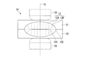
- FIG. 6 is a spot weld cross-sectional view illustrating a schematic configuration of a spot weld 10 formed on a lap weld member used as, for example, an automotive part, according to an embodiment of the present invention.
- the lap weld member according to the present embodiment is formed by joining steel plate members S ⁇ b> 1 and S ⁇ b> 2 via spot welds 10.
- the nugget 12 is a steel plate centered on the center line CL of the electrode 50 by energization from the pair of resistance spot welding electrodes 50, 50 sandwiching the steel plate members S 1, S 2 in their thickness direction. It is formed in the overlapping part of member S1, S2.
- the molten metal generated by energization solidifies in the thickness direction due to heat removal to the electrode 50 in the region near the center line CL in contact with the electrode 50, and in the region away from the center line CL of the electrode 50. Solidification proceeds toward the nugget center direction (toward the electrode center line CL) in addition to the plate thickness direction.
- the nugget 12 has a region 12A where dendrite grows in the thickness direction and a region 12B where dendrite grows intersecting the thickness direction.
- nugget end 12E when the overlapping portion is viewed from the thickness direction
- nugget end region 12B the region 12A A region from the meeting portion 12C of the region 12B to the nugget end 12E
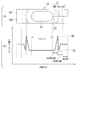
- FIG. 7 is a cross-sectional view of the spot welded portion for explaining the spot welded portion 10 for welding the overlapped portion.
- the spot welded portion 10 is formed around the nugget 12 formed by spot welding and around the nugget 12. HAZ14 by spot welding.
- the HAZ 14 has a HAZ hardened portion 14H formed adjacent to the nugget 12, and a HAZ softened portion 14T formed around the HAZ hardened portion 14H. Further, in the vicinity of the inner peripheral portion of the HAZ softened portion 14T, a HAZ softest portion 14L having the lowest Vickers hardness is formed.
- a symbol D illustrated in FIG. 7 indicates a distance between the nugget end 12E and the HAZ most softened portion 14L.
- FIG. 8 is a diagram for explaining energization conditions in resistance spot welding according to the present embodiment.
- the short-time energization condition C11 according to the present embodiment has an energization current I11 higher than the energization current I21 of the normal energization condition C21 and a current with an energization time T11 shorter than the conventional normal energization time T21.
- Resistance spot welding is performed by first conducting a single energization.
- a broken line indicates the first energization C21 (current value I21, energization time T21) under normal conditions, where current value I11> current value I21, energization time T11 (cyc) ⁇ energization time T21 (cyc). It is.
- the short-time energization condition C11 is shown from the middle of the time axis of the normal energization condition C21 in order to align the energization completion timing.
- the molten metal generated when the nugget 12 is formed by energization is rapidly cooled after completion of the single energization and passes through the Ms point. Since the temperature is lowered to the Mf point or lower, martensite is generated.
- the joint melts in a shorter time than the normal energization condition C21.
- the nugget 12 is formed. Therefore, according to the short-time energization condition C11, an excessive heat flow around the nugget 12 is suppressed, the HAZ hardened portion is reduced, and the distance D between the nugget end 12E and the HAZ most softened portion 14L is reduced.
- the stress concentration on the nugget end region 12B can be reduced by concentrating the strain on a portion other than the nugget end region 12B at the time of peeling only by the single energization, thereby improving the peel strength.
- spot welding part 10 formed by the single electricity supply of short-time energization conditions C11 as it is, and also, after the predetermined rest time Ts passes, the formed spot welding part 10 is post-energization conditions.
- Post-energization by C12 that is, second energization may be performed.
- the nugget 12 can be tempered when the spot weld 10 formed under the short-time energization condition C11 is energized under the post-energization condition C12 (current value I12, energization time T12) after the energization is stopped for the rest time Ts. Tempered martensite can be obtained without increasing the temperature (approximately 550 to 600 ° C.) to Ac 1 or less and then gradually cooling to re-quenze HAZ 14.
- the current value I11 is made larger than the current value I21 in the normal energization condition C21, and the energization time T11 is made shorter than the energization time T21 in the normal energization condition C21.
- the temperature is raised over time, heat conduction to the surroundings of the heat generated by energization is not promoted, and the temperature of the HAZ 14 is less likely to be higher than normal conditions.
- the width of the HAZ hardened portion 14H is reduced, and the distance D between the nugget end 12E and the HAZ most softened portion 14L is considered to be reduced.
- the width of the HAZ cured portion 14H is small, so that the nugget 12 and the HAZ cured portion 14H are sufficiently tempered. For this reason, it is suppressed that a part with high Vickers hardness is formed between the nugget end 12E and the HAZ most softened portion 14L. That is, since the HAZ hardened portion 14H is uniformly softened, the deformation becomes easy and the stress at the time of peeling to the nugget end region 12B is reduced, so that the peel strength can be improved.
- the Vickers hardness between the HAZ most softened portion 14L and the nugget end 12E is reduced, and the Vickers hardness of the HAZ most softened portion 14L is 100%. In this case, it can be set to 120% or less, and the toughness of the spot welded portion 10 can be sufficiently secured.
- FIG. 9A and FIG. 9B show that “(a) short-time energization condition” and “(b) normal condition” according to the present embodiment are applied to a 1500 MPa class hot stamp material having a plate thickness of 1.6 mm for the first time. It is a figure which shows the case where it supplies with electricity, FIG. 9A is a spot weld part sectional drawing, and FIG. 9B is a graph which shows the hardness distribution of the spot weld part 10. FIG. Regarding the measurement of the hardness distribution, as shown in FIG.
- the Vickers hardness is 1 ⁇ 4 of the plate thickness from the joint surface with the steel plate members S1 and S2 to the steel plate member S1 side and to the inner side of the steel plate member S1.
- measurement was performed at a load of 9.8 N based on JIS Z 2244 at a pitch of 0.5 mm.
- “open diamond” indicates a short-time energization condition
- “open circle” indicates a normal energization condition.
- the short-time energization condition is energization time: 9 ⁇ cyc
- the normal condition is energization time: 20 ⁇ cyc
- the current value is adjusted so that each nugget diameter is 4 ⁇ t (mm) (t is the plate thickness).
- 9A and 9B it is understood that the distance D from the nugget end 12E to the HAZ most softened portion 14L is reduced by performing the first energization under “(a) short-time energization condition”.
- FIG. 10A, 10B, 11 and 12 the equivalent strain in the case where the short-time energization and the energization under the normal conditions are performed will be described with reference to FIGS. 10A, 10B, 11 and 12.
- FIG. 10A, 10B, 11 and 12 the equivalent plastic strain in the case of “(a) short-time energization conditions”, “(b) normal conditions” and “(c) no HAZ softening” is obtained. It was. This will be described in detail below.
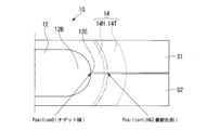
- FIG. 10A is a cross-sectional view of a spot welded portion illustrating an analysis model of a single energized test piece energized for the first time under “(a) short-time energization condition” with a distance D from the nugget end 12E to the HAZ softened portion 14L being 0.75 mm
- FIG. 10B is a cross-sectional view of a spot welded portion illustrating an analysis model of a single energized test piece that is energized for the first time under normal conditions with a distance D from the nugget end 12E to the HAZ softened portion 14L of 1.5 mm.
- the hardness distribution of the HAZ softened part was changed stepwise from the hardness of the softest part to the hardness of the base material part based on the measurement result shown in FIG. 9B.
- Position 1 indicates the HAZ most softened portion 14L
- Position 2 indicates the nugget end 12E.
- the analysis model simulates “(a) short-time energization condition” shown in FIG. 10A, “(b) normal condition” shown in FIG. 10B, and “(c) no HAZ softening”. Three patterns were used.
- FIG. 11 shows “(b) normal conditions” for an analysis model composed of spot welds of “(a) short-time energization conditions”, “(b) normal conditions”, and “(c) no HAZ softening”. It is a graph which shows each equivalent plastic strain in Position1 shown to FIG. 10A when the spot welded part of this is a cross tension test with the load fractured
- Position 1 in the analysis model “(c) HAZ not softened” is set at the same position as “(b) normal condition”.
- the equivalent plastic strain in Position 1 is about 0.032 in “(a) short-time energization condition”, and 0.013 in “(b) normal condition”, “(c) Compared with about 0.018 of “no HAZ softening”, it was greatly increased.
- FIG. 12 shows an analysis model composed of spot welds of “(a) short-time energization condition”, “(b) normal condition”, and “(c) no HAZ softening”. It is a graph which shows each equivalent plastic strain in Position2 shown to FIG. 10A when a welded part carries out the cross tension test with the load fractured
- Position 2 in the analysis model of “(c) HAZ not softened” is set at the same position as “(b) normal condition”.
- the equivalent plastic strain in Position 2 is about 0.010 in “(a) short-time energization condition”, and 0.0115 in “(b) normal condition”, “( c) decreased compared to about 0.0118 of “no HAZ softening”.
- “(b) normal condition” and “(c) no HAZ softening” are compared, at the HAZ softening position of “(b) normal condition”, whether or not HAZ softening affects the equivalent plastic strain in the end region of the nugget. The impact was minor.
- the HAZ softened portion 14T has almost no strain reducing effect on the nugget end region 12B at the time of peeling. concentrate. As a result, it has been found that strain concentration on the nugget end region 12B is reduced. That is, if the “short-time energization condition” is used, the peel strength can be increased by this effect.
- FIG. 13A is a diagram showing the relationship between the thickness t (mm) constituting the overlapping portion and the distance D (mm) from the nugget melting boundary (nugget end) to the HAZ most softened portion.
- “open circles” indicate conventional 980 MPa grade DP steel by single energization.
- “Outlined diamond” indicates a conventional 1500 MPa class hot stamping steel with a single current.
- the plate thickness t (mm) in FIG. 13A is t (mm) if there is a single steel plate member having the highest tensile strength among a plurality of steel plate members, while the maximum tensile strength is obtained. If there are a plurality of high steel plate members, the thickness of the steel plate member having the thinnest thickness among them is defined as t (mm).
- the cross tensile strength is lower when the base material strength is higher, so that the higher the base material strength tends to break.
- plate set from which the board thickness differs in the same steel type it fractures
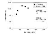
- FIG. 13B is a diagram for explaining the relationship between the distance D from the nugget end 12E of the spot welded portion to the HAZ softened portion and the cross tensile strength when the nugget diameter is 4 ⁇ t in the 1500 MPa class hot stamp material.
- the distance D (mm) between the nugget end 12E and the HAZ most softened portion 14L is t 0.2 (mm) or less
- the cross tensile strength is improved to about 7 kN and the plug is stable. It can be made to break.
- the cross tensile strength is improved to about 8 kN and further stable.
- the plug can be broken, which is more preferable.
- the cross tensile strength is improved by reducing the distance D from the nugget end 12E of the spot welded portion to the HAZ softened portion 14T.
- the hardness from the base material to the nugget end region 12B (including the nugget end region 12B) at the overlapping interface of these two steel plate members is the maximum in Vickers hardness with respect to the HAZ softening portion 14L.
- the value gradually decreases toward the nugget end 12E within a range of about 115%, or is equivalent to the hardness of the HAZ most softened portion 14L.
- the effect of improving the joint strength is prominent when the fracture mode changes from nugget fracture (interface fracture, partial plug fracture) to plug fracture.
- nugget fracture interface fracture, partial plug fracture
- the HAZ softened portion 14T of the HAZ softened portion 14T is used for a joint in which the nugget 12 itself lacks the toughness and cracks propagate into the nugget and a plug fracture is not obtained.
- the distance D (mm) from the nugget end 12E to the HAZ most softened portion 14L is By satisfying D ⁇ t 0.2 (1), sufficient improvement in joint strength can be obtained. Therefore, in the lap weld member according to the present embodiment, the distance D from the nugget end 12E to the HAZ most softened portion 14L satisfies the above expression (1). Further, when the distance D (mm) from the nugget end 12E to the softest part of the HAZ satisfies the formula D ⁇ 0.75 ⁇ (t 0.2 ) (1A), the fracture mode can be more reliably achieved. This is preferable in that the plug can be broken.
- the overlapping portion of the plurality of steel plate members has the nugget 12, the HAZ 14 formed around the nugget 12, and the softened portion 14L having the lowest Vickers hardness in the HAZ 14.
- the spot weld 10 is formed by resistance spot welding.
- the Vickers hardness of the softest portion 14L is composed of tempered martensite between the center portion of the nugget 12 formed in the resistance spot welding step and the softest portion 14L.
- a tempering region that is 120% or less is formed when the thickness is 100%.
- the tempering region is preferably formed by post-energization, but is not limited to post-energization, and can be performed by, for example, laser beam irradiation.
- the tempered region has a Vickers hardness of 120% or less when the Vickers hardness of the most softened portion 14L is 100%.
- a tempering region can be formed between the center portion of the nugget 12 and the softest portion 14L.
- the plate thickness t (mm) here, if a single steel plate member having the highest tensile strength among a plurality of steel plate members is singular, the plate thickness is set to t (mm). If there are a plurality of high steel plate members, the thickness of the steel plate member having the thinnest thickness among them is defined as t (mm).
- FIG. 14 shows a short-time energization condition (9 ⁇ cyc), a normal condition (20 ⁇ cyc), a two-stage energization condition (the first process energization time 11 ⁇ cyc, the welding current 4 kA, the second process energization time 9 ⁇ cyc). ) Is applied to a 1800 MPa class hot stamp material having a plate thickness of 1.6 mm.
- FIG. 15 is a graph showing the distribution of Vickers hardness based on the distance from the nugget end of the spot weld formed under the conditions shown in FIG. As shown in FIG. 14 and FIG.
- the HAZ softening position is set to the nugget end than the conventional one while having an appropriate current range substantially equal to the conventional one.
- the area 12B can be approached.
- energization time T 1 (second), energization cycle time cyc (second), and plate thickness t (mm) are 5t ⁇ cyc ⁇ T 1 ⁇ (5t + 8) ⁇ cyc (3) formula)
- a preheating current I (kA) is applied to the overlapping portion.
- the energization time is T 2 (seconds) and the time of one cycle of the resistance spot welding energization is cyc (seconds), 5t ⁇ cyc ⁇ T 2 ⁇ (5t + 4) ⁇ cyc (4)
- the nugget is formed by supplying the welding current I 0 (kA) equal to or less than the generation current of the dust to the overlapping portion after satisfying the equation (4).
- the relationship between the preheating current I (kA) and the welding current I 0 (kA) is 0.3I 0 ⁇ I ⁇ 0.7I 0 (5) is satisfied.
- the energization time T 1 (seconds) is 5 t ⁇ cyc or more and the preheating current I (kA) is 0.3 I 0 or more, that is, the welding current in the resistance spot welding process for forming the nugget. Since it is 30% or more of I 0 , the preheating effect is sufficient and a desired appropriate current range can be secured, which is preferable. Further, the energization time T 1 (second) is (5t + 4) ⁇ cyc or less and the preheating current I (kA) is 0.7I 0 or less, that is, the welding current I 0 in the resistance spot welding process for forming the nugget. Since it is 70% or less, the distance D between the nugget end 12E and the HAZ most softened portion 14L can be reduced, which is preferable.
- the distance D (mm) to 14L can be t 0.2 or less, and the peel strength at the spot welded portion can be stably improved. Further, by adjusting the energization time so that the distance D (mm) is 0.75 ⁇ (t 0.2 ) or less, a spot welded portion in which the fracture mode is plug fracture can be obtained more reliably. The peel strength can be improved.
- the above-described tempering step for example, tempering by post-energization
- tempering by post-energization so that the nugget end region 12B is tempered to the lap weld thus obtained, tempered martensite.
- a tempering region whose Vickers hardness is 120% or less when the Vickers hardness of the softest part 14L is 100% is formed between the center part of the nugget 12 and the softest part 14L. it can. Therefore, a lap weld member having a conventional nugget diameter, excellent peel strength, and high joint strength can be produced.
- the energization condition is adjusted for a short time so that the nugget end 12E and the HAZ most softened portion 14L are close to each other, and in the subsequent tempering step, the Vickers hardness in the tempered region is reduced to the most softened portion. It is necessary to be 120% or less of the 14 L Vickers hardness. However, in order to obtain a more suitable effect, the Vickers hardness of the tempered region is preferably 115% or less, more preferably 110% or less of the Vickers hardness of the most softened portion 14L. In addition, the lower limit value of the Vickers hardness of the tempering region is not specified.
- a lap weld member has a base material tensile strength of 980 MPa or higher
- interface fracture and partial plug fracture tend to occur, and the joint strength tends to decrease.
- the present embodiment has an effect on a steel plate member that is softened by spot welding, but is preferably applied to a high-tensile steel plate having a base material tensile strength of 980 MPa or higher.
- the base material is full martensite, the HAZ softening amount is large, and the effect of this embodiment is remarkable.
- the lap welding member according to the present embodiment is not limited to the plate thickness and type (for example, DP, TRIP, etc.) of each steel plate member of the overlapped portion of two or more steel plate members, and further, whether or not plating is present. .
- the board set which overlaps two sheets of the same kind of steel plate is demonstrated, it is not limited to this, Even if it is a board set of 3 or more sheets, it is not limited to this. Has an effect.
- FIG. 16 is a diagram illustrating a schematic configuration of the spot welded portion 10 formed under the energization condition according to the present embodiment when a hot stamp material is used as the steel plate members S1 and S2. More specifically, FIG. 16A is a cross-sectional view of a spot welded portion after a short-time energization, and FIG. 16B is a cross-sectional view of a spot welded portion after a post-energization. . FIG. 16C is a graph showing the distribution of Vickers hardness after single energization and after post-energization. Moreover, FIG. 17 is a figure which illustrates notionally the change of the Vickers hardness of the spot welding part after single electricity supply and after after electricity supply.
- the distance D between the nugget end 12E and the HAZ most softened portion 14L is reduced to about 1 mm. Since the distance D between the nugget end 12E and the HAZ most softened portion 14L by energization under the conventional normal condition is about 1.5 mm, the distance is significantly reduced. As a result, stress concentration around the nugget end 12E can be relaxed.
- the HAZ hardened portion 14H can be tempered sufficiently within the range indicated by dot hatching in FIG.
- the spot welding portion 10 is formed by applying the energization condition according to the present invention to the hot stamp materials S1 and S2, a single energization is performed for a short time as shown in FIGS.
- the HAZ cured portion 14H has a Vickers hardness substantially equal to that of the nugget 12.
- the nugget 12 and the HAZ hardened portion 14H are sufficiently tempered, and the space between the HAZ most softened portion 14L and the nugget end 12E is in the Vickers hardness.
- the hardness is the same as that of the HAZ softened portion 14L, or the maximum value of the hardness is about 115% of the HAZ softened portion 14L, and the stress in the nugget end region 12B is sufficiently relaxed. As a result, the peel strength of the spot welded portion 10 in the hot stamp material can be improved. If the nugget end region 12B is tempered, it is not necessary that the entire nugget 12 is tempered.
- the maximum hardness between the nugget 12 and the HAZ most softened portion 14L in the Vickers hardness is HAZ. It can be made into the range of about 120% or less to the softest part 14L. As a result, the toughness of the nugget 12 and the HAZ hardened portion is improved, and the peel strength can be improved.
- the maximum Vickers hardness between the nugget end 12E and the HAZ most softened portion 14L is 120% or less of the Vickers hardness of the HAZ most softened portion 14L, preferably 115% or less, more preferably 110% or less. Even if the entire nugget 12 is not tempered, the joint strength is improved.
- the short-term energization conditions are adjusted so that the nugget end and the HAZ most softened portion are brought close to each other, and the maximum value of the Vickers hardness between the center portion of the nugget 12 and the HAZ most softened portion 14L after the post-energization A range of 115% is preferable with respect to the softest portion 14L.
- the energization condition for a short time bringing the nugget end and the HAZ most softened portion closer to each other, the maximum value of the Vickers hardness between the nugget and the HAZ most softened portion after the post-energization is applied to the HAZ softest portion 14L.
- the range of 110% is more preferable.
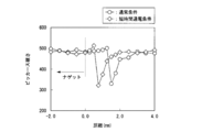
- FIG. 18 is a graph showing the hardness distribution of the spot weld in one-time energization when the short-time energization condition and the normal energization condition according to the present embodiment are applied to a 1800 MPa class hot stamp material having a plate thickness of 1.8 mm. It is.
- FIG. 19 shows the hardness distribution of the spot weld after post-energization when the short-time energization condition and the normal energization condition according to this embodiment are applied to a 1800 MPa class hot stamp material with a plate thickness of 1.8 mm. It is a graph to show. In FIG.
- “outlined diamond” indicates the hardness distribution of the spot welded portion when the spot welded portion is formed by the main energization adopting the short-time energization condition of energization time 9 ⁇ cyc (seconds). Further, “open circle” indicates the hardness distribution of the spot welded portion when the spot welded portion is formed by main energization adopting the normal condition of energization time 22 ⁇ cyc (seconds). In FIG. 19, “open diamond” is a case where a spot weld is formed by main energization adopting a short-time energization condition of energization time 9 ⁇ cyc (seconds), and then tempered by post-energization.
- the distance from the nugget edge to the HAZ softest part is closer in the short-time energization condition indicated by “open diamond” than in the normal condition indicated by “open circle”.
- the HAZ softest part formed during the main energization is the end region of the nugget. Therefore, there is a place with high hardness between the nugget and the softest part (a position about 1 mm from the end region of the nugget).
- the HAZ most softened portion formed during the main energization is close to the end region of the nugget.
- the Vickers hardness of the HAZ and the nugget (including the nugget end region 12B) up to 12B can be 120% or less of the hardness of the HAZ most softened portion.
- strain concentration around the nugget end 12E can be alleviated when the HAZ softened portion formed during the main energization is closer to the nugget end 12E.
- shortening the energization time for forming the nugget 12 is effective from the viewpoint of improving the joint strength by bringing the HAZ softened position closer to the end region of the nugget.
- FIG. 20 is a diagram conceptually illustrating the change in the HAZ of the spot weld after single energization and post energization when the short-time energization condition according to the present embodiment is applied to the DP material or TRIP material.
- FIG. 20A is a cross-sectional view of a spot weld.
- the HAZ hardened portion 14H is nugget in the nugget 12 and the Vickers hardness in a state of being simply energized for a short time. Is almost equivalent.
- the nugget 12 and the HAZ hardened portion 14H are different from the hardness distribution of the hot stamp material shown in FIG. 17 in that the nugget 12 and the HAZ cured portion 14H are very hard as compared with the base material of the DP material or the TRIP material.
- the nugget 12 and the HAZ hardened portion 14H are sufficiently tempered, and there is a Vickers hardness between the HAZ softest portion 14L and the nugget end 12E. Is about 115% of the HAZ softened portion 14L, and the stress in the nugget end region 12B is sufficiently relaxed. As a result, the peel strength of the spot welded portion 10 in the DP material or TRIP material can be improved. If the nugget end region 12B is tempered, it is not necessary that the entire nugget 12 is tempered. In addition, the dashed-two dotted line shown to (c) of FIG. 20 has shown the hardness distribution before post-energization.
- a nugget and a HAZ hardening part are formed by laser irradiation, for example. It may be tempered.
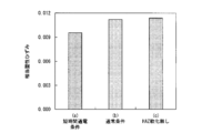
- an appropriate current range (generally, a nugget diameter of 4 ⁇ The current range from the current value at which t can be obtained to the occurrence of dust is reduced.
- Condition (1) is a short-time single energization condition
- (2) is a conventional single energization condition
- (3) is a two-stage energization condition.
- the two-stage energization has an appropriate current range equivalent to that of conventional single energization, and the HAZ softest part is It became possible to approach the nugget edge.
- the welding current was adjusted so that a nugget diameter of 4 ⁇ t (mm) was obtained.
- a condition effective for improving the peel strength that is, a condition for softening the end region of the nugget was selected.
- Condition a is a conventional single energization condition
- condition b is a conventional post-energization condition
- Condition A1 is a short-time single energizing condition
- condition A2 is a two-stage energizing condition
- conditions B1 and B2 are post-energized with respect to conditions A1 and A2, respectively.
- the welding current was adjusted so that a nugget diameter of 4 ⁇ t was obtained.
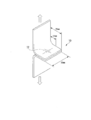
- the joint strength was measured by a cross tension test based on JIS Z3137 (1999) in the case of a cruciform joint, and by a test showing a schematic diagram of FIG. 21 in the case of an L-shaped joint. More specifically, in the L-shaped tensile test, as shown in FIG.
- the bent portions of two test pieces formed by bending a steel plate into an L shape are overlapped with each other, and a nugget is formed by resistance spot welding on the overlapped portion.
- the spot welded portion 10 having 12 was formed and joined, and then the strength until the spot welded portion 10 was broken was measured as the joint strength by pulling in the direction in which the overlapped portion was peeled off.
- Table 4 shows the welding conditions.
- t is the thickness of the steel sheet, and I 0 is adjusted so that a nugget diameter of 4 ⁇ t (mm) is obtained for each set.
- the distance D is the distance from the nugget end region to the HAZ softest portion.
- Table 3 summarizes the joint strength improvement effect under conditions A1 and A2.
- Table 3 is a table for explaining examples related to single energization.
- the joint strength was improved by about 25% as compared with the case of the condition a by applying the current for a short time of the condition A1.
- Table 4 summarizes the joint strength improvement effects under conditions B1 and B2.
- Table 4 is a table for explaining an example when post-energization is performed.
- the joint strength was improved in all steel types and plate thicknesses as compared with the conventional single-current condition of condition a. This is considered to be an effect of obtaining an optimum hardness distribution that relaxes stress concentration on the nugget end, in addition to tempering the nugget end and improving toughness as in the conventional post-energization technique.
- the fracture mode is changed from the interface fracture to the plug fracture compared to the case of the condition b. About 114%.
- a plurality of steel plate members are joined to each other at an overlap portion, and the overlap weld member in which at least one of the plurality of steel plate members includes martensite is joined by a spot weld portion. Since the peel strength at the welded portion can be improved, it is industrially applicable.
Landscapes
- Engineering & Computer Science (AREA)
- Chemical & Material Sciences (AREA)
- Mechanical Engineering (AREA)
- Materials Engineering (AREA)
- Metallurgy (AREA)
- Organic Chemistry (AREA)
- Physics & Mathematics (AREA)
- Thermal Sciences (AREA)
- Crystallography & Structural Chemistry (AREA)
- Resistance Welding (AREA)
Priority Applications (7)
| Application Number | Priority Date | Filing Date | Title |
|---|---|---|---|
| MX2015001640A MX373569B (es) | 2012-08-10 | 2013-08-12 | Miembro soldado sobrepuesto, parte de autómovil, método de soldadura de porción sobrepuesta, y método de fabricación de miembro soldado sobrepuesto. |
| JP2014529593A JP5713147B2 (ja) | 2012-08-10 | 2013-08-12 | 重ね合せ溶接部材、自動車用部品、重ね合せ部の溶接方法、及び、重ね合せ溶接部材の製造方法 |
| IN483DEN2015 IN2015DN00483A (https=) | 2012-08-10 | 2013-08-12 | |
| KR1020157002804A KR101737712B1 (ko) | 2012-08-10 | 2013-08-12 | 겹침 용접 부재, 자동차용 부품, 겹침부의 용접 방법 및 겹침 용접 부재의 제조 방법 |
| US14/418,403 US10543562B2 (en) | 2012-08-10 | 2013-08-12 | Overlap-welded member, automobile part, method of welding overlapped portion, and method of manufacturing overlap-welded member |
| CN201380041567.7A CN104520052B (zh) | 2012-08-10 | 2013-08-12 | 搭接焊构件、汽车用部件、重叠部的焊接方法、和搭接焊构件的制造方法 |
| US16/709,402 US20200156177A1 (en) | 2012-08-10 | 2019-12-10 | Overlap-welded member, automobile part, method of welding overlapped portion, and method of manufacturing overlap-welded member |
Applications Claiming Priority (2)
| Application Number | Priority Date | Filing Date | Title |
|---|---|---|---|
| JP2012-178691 | 2012-08-10 | ||
| JP2012178691 | 2012-08-10 |
Related Child Applications (2)
| Application Number | Title | Priority Date | Filing Date |
|---|---|---|---|
| US14/418,403 A-371-Of-International US10543562B2 (en) | 2012-08-10 | 2013-08-12 | Overlap-welded member, automobile part, method of welding overlapped portion, and method of manufacturing overlap-welded member |
| US16/709,402 Division US20200156177A1 (en) | 2012-08-10 | 2019-12-10 | Overlap-welded member, automobile part, method of welding overlapped portion, and method of manufacturing overlap-welded member |
Publications (1)
| Publication Number | Publication Date |
|---|---|
| WO2014025063A1 true WO2014025063A1 (ja) | 2014-02-13 |
Family
ID=50068276
Family Applications (1)
| Application Number | Title | Priority Date | Filing Date |
|---|---|---|---|
| PCT/JP2013/071841 Ceased WO2014025063A1 (ja) | 2012-08-10 | 2013-08-12 | 重ね合せ溶接部材、自動車用部品、重ね合せ部の溶接方法、及び、重ね合せ溶接部材の製造方法 |
Country Status (7)
| Country | Link |
|---|---|
| US (2) | US10543562B2 (https=) |
| JP (1) | JP5713147B2 (https=) |
| KR (1) | KR101737712B1 (https=) |
| CN (1) | CN104520052B (https=) |
| IN (1) | IN2015DN00483A (https=) |
| MX (1) | MX373569B (https=) |
| WO (1) | WO2014025063A1 (https=) |
Cited By (15)
| Publication number | Priority date | Publication date | Assignee | Title |
|---|---|---|---|---|
| CN104668798A (zh) * | 2015-02-03 | 2015-06-03 | 上海诚烨汽车零部件有限公司 | 高强钢焊接工艺优化方法 |
| JP2016032834A (ja) * | 2014-07-31 | 2016-03-10 | 新日鐵住金株式会社 | 重ね溶接部材、重ね溶接部材の重ね抵抗シーム溶接方法及び重ね溶接部を備える自動車用重ね溶接部材 |
| JP2016055337A (ja) * | 2014-09-11 | 2016-04-21 | 高周波熱錬株式会社 | 溶接方法及び溶接構造物 |
| JP2016109691A (ja) * | 2014-12-09 | 2016-06-20 | Jfeスチール株式会社 | スポット溶接継手用薄鋼板、スポット溶接継手の破断様式の判定方法、スポット溶接継手のはく離破断強度の予測方法及びスポット溶接継手のプラグ破断強度の予測方法 |
| JP2016209917A (ja) * | 2015-05-12 | 2016-12-15 | Jfeスチール株式会社 | はく離破断強度に優れたスポット溶接部の判定方法 |
| JP2016209919A (ja) * | 2015-05-12 | 2016-12-15 | Jfeスチール株式会社 | スポット溶接部材 |
| JPWO2014208747A1 (ja) * | 2013-06-27 | 2017-02-23 | 高周波熱錬株式会社 | 溶接構造部材及び溶接方法 |
| JP2019098345A (ja) * | 2017-11-29 | 2019-06-24 | ダイハツ工業株式会社 | スポット溶接方法及びスポット溶接装置 |
| WO2020241500A1 (ja) * | 2019-05-24 | 2020-12-03 | 日本製鉄株式会社 | スポット溶接継手、及びスポット溶接継手の製造方法 |
| JP7332065B1 (ja) * | 2021-10-12 | 2023-08-23 | Jfeスチール株式会社 | 抵抗スポット溶接継手およびその抵抗スポット溶接方法 |
| WO2023181680A1 (ja) * | 2022-03-25 | 2023-09-28 | Jfeスチール株式会社 | 抵抗スポット溶接継手およびその製造方法 |
| JP7480929B1 (ja) * | 2022-12-15 | 2024-05-10 | Jfeスチール株式会社 | 抵抗スポット溶接継手およびその抵抗スポット溶接方法 |
| WO2024127866A1 (ja) * | 2022-12-15 | 2024-06-20 | Jfeスチール株式会社 | 抵抗スポット溶接継手およびその抵抗スポット溶接方法 |
| JP7785668B2 (ja) | 2019-11-13 | 2025-12-15 | ポスコホールディングス インコーポレーティッド | 冷間成形用強化部材及びこれを用いて製造された部品 |
| WO2026074859A1 (ja) * | 2024-10-01 | 2026-04-09 | Jfeスチール株式会社 | 抵抗スポット溶接継手およびその製造方法、並びに溶接継手のはく離強度評価方法 |
Families Citing this family (25)
| Publication number | Priority date | Publication date | Assignee | Title |
|---|---|---|---|---|
| BR112017020590A2 (pt) * | 2015-03-30 | 2018-07-03 | Nippon Steel & Sumitomo Metal Corp | método de soldagem por pontos de chapa de aço chapeada |
| JP5909014B1 (ja) | 2015-06-08 | 2016-04-26 | オリジン電気株式会社 | 接合部材の製造方法及び接合部材製造装置 |
| US10272515B2 (en) * | 2015-09-15 | 2019-04-30 | GM Global Technology Operations LLC | Power pulse method for controlling resistance weld nugget growth and properties during steel spot welding |
| EP3147065B1 (en) * | 2015-09-23 | 2019-07-24 | Neturen Co., Ltd. | Welding method |
| WO2017064817A1 (ja) * | 2015-10-16 | 2017-04-20 | 新日鐵住金株式会社 | スポット溶接継手およびスポット溶接方法 |
| CN105252152B (zh) * | 2015-11-26 | 2017-08-01 | 重庆大江工业有限责任公司 | 一种减小装甲车车体变形的焊接加工方法 |
| JP2017108595A (ja) * | 2015-12-11 | 2017-06-15 | 日本電産株式会社 | 振動モータ |
| JP6055154B1 (ja) * | 2016-08-29 | 2016-12-27 | オリジン電気株式会社 | 接合部材の製造方法及び接合部材製造装置 |
| US11235415B2 (en) * | 2017-02-28 | 2022-02-01 | Nippon Steel Corporation | Fillet welded joint and method of manufacturing thereof |
| JP6665140B2 (ja) * | 2017-09-13 | 2020-03-13 | 本田技研工業株式会社 | 抵抗溶接方法及び抵抗溶接装置 |
| CN108161201B (zh) * | 2017-12-12 | 2021-02-26 | 广州亨龙智能装备股份有限公司 | 电容储能焊工艺在销轴与热成形马氏体钢焊接的应用 |
| KR101999005B1 (ko) * | 2017-12-22 | 2019-07-10 | 주식회사 포스코 | 아연도금강판의 점용접 균열 방지방법 |
| US12030131B2 (en) * | 2018-05-31 | 2024-07-09 | Nippon Steel Corporation | Spot welded joint, vehicle framework component provided with spot welded joint, and method of manufacturing spot welded joint |
| CN112930299B (zh) * | 2018-10-31 | 2021-11-02 | 日本制铁株式会社 | 汽车骨架构件 |
| CN113573836B (zh) * | 2019-03-14 | 2023-07-14 | 日本制铁株式会社 | 焊接接头的制造方法、焊接接头、回火装置以及焊接装置 |
| CN113597475B (zh) * | 2019-03-26 | 2022-12-02 | 日本制铁株式会社 | 钢板和构件 |
| MX2021014596A (es) * | 2019-05-28 | 2022-01-11 | Jfe Steel Corp | Soldadura por puntos de resistencia, metodo de soldadura por puntos de resistencia, junta soldada por puntos de resistencia y metodo para fabricar la junta soldada por puntos de resistencia. |
| CN110548976A (zh) * | 2019-08-08 | 2019-12-10 | 沈阳大学 | 一种1800MPa级超高强度热成形钢板电阻点焊工艺 |
| WO2021108768A1 (en) * | 2019-11-27 | 2021-06-03 | Cascade Corporation | Connection between forks and hangers on forks |
| JP6958765B1 (ja) * | 2020-03-05 | 2021-11-02 | Jfeスチール株式会社 | 抵抗スポット溶接方法および抵抗スポット溶接継手の製造方法 |
| CN112222667B (zh) * | 2020-09-07 | 2022-06-28 | 中国科学院上海光学精密机械研究所 | 一种高强度钢板的点焊接头及其制造方法 |
| JP7376458B2 (ja) * | 2020-11-27 | 2023-11-08 | トヨタ自動車株式会社 | 抵抗スポット溶接方法 |
| MX2023007934A (es) * | 2021-04-22 | 2023-07-14 | Nippon Steel Corp | Miembro de bastidor. |
| MX2024004028A (es) | 2021-10-12 | 2024-04-23 | Jfe Steel Corp | Union soldada por puntos de resistencia y metodo de soldadura por puntos de resistencia para la misma. |
| JP2024033313A (ja) * | 2022-08-30 | 2024-03-13 | 日本製鉄株式会社 | スポット溶接継手、スポット溶接継手の製造方法、及び自動車部品 |
Citations (3)
| Publication number | Priority date | Publication date | Assignee | Title |
|---|---|---|---|---|
| JP2009001839A (ja) * | 2007-06-19 | 2009-01-08 | Kobe Steel Ltd | 高強度スポット溶接継手 |
| WO2011013793A1 (ja) * | 2009-07-31 | 2011-02-03 | 高周波熱錬株式会社 | 溶接構造部材及び溶接方法 |
| WO2011025015A1 (ja) * | 2009-08-31 | 2011-03-03 | 新日本製鐵株式会社 | スポット溶接継手およびスポット溶接方法 |
Family Cites Families (7)
| Publication number | Priority date | Publication date | Assignee | Title |
|---|---|---|---|---|
| JP2002103054A (ja) | 2000-09-29 | 2002-04-09 | Nippon Steel Corp | 高強度鋼板のスポット溶接方法 |
| JP2008229720A (ja) * | 2007-02-22 | 2008-10-02 | Kobe Steel Ltd | 引張強度に優れた高張力鋼板スポット溶接継手、それを有する自動車部品、および高張力鋼板のスポット溶接方法 |
| US7591173B2 (en) * | 2007-03-06 | 2009-09-22 | Gm Global Technology Operations, Inc. | Method and apparatus for monitoring the restriction level of a vehicular air filter element |
| JP2009000697A (ja) | 2007-06-19 | 2009-01-08 | Sumitomo Metal Ind Ltd | レーザ溶接方法ならびにレーザ溶接品 |
| JP5201116B2 (ja) | 2008-10-16 | 2013-06-05 | Jfeスチール株式会社 | 高強度鋼板の抵抗スポット溶接方法 |
| JP2012187617A (ja) | 2011-03-11 | 2012-10-04 | Nissan Motor Co Ltd | 高張力鋼板の接合体、および高張力鋼板の抵抗溶接方法 |
| DE102011113267A1 (de) | 2011-09-13 | 2012-04-19 | Daimler Ag | Verfahren zur lokalen Wärmenachbehandlung thermischer Fügeverbindungen ultrahochfester Metallbauteile |
-
2013
- 2013-08-12 IN IN483DEN2015 patent/IN2015DN00483A/en unknown
- 2013-08-12 CN CN201380041567.7A patent/CN104520052B/zh active Active
- 2013-08-12 WO PCT/JP2013/071841 patent/WO2014025063A1/ja not_active Ceased
- 2013-08-12 JP JP2014529593A patent/JP5713147B2/ja active Active
- 2013-08-12 US US14/418,403 patent/US10543562B2/en active Active
- 2013-08-12 MX MX2015001640A patent/MX373569B/es active IP Right Grant
- 2013-08-12 KR KR1020157002804A patent/KR101737712B1/ko active Active
-
2019
- 2019-12-10 US US16/709,402 patent/US20200156177A1/en not_active Abandoned
Patent Citations (3)
| Publication number | Priority date | Publication date | Assignee | Title |
|---|---|---|---|---|
| JP2009001839A (ja) * | 2007-06-19 | 2009-01-08 | Kobe Steel Ltd | 高強度スポット溶接継手 |
| WO2011013793A1 (ja) * | 2009-07-31 | 2011-02-03 | 高周波熱錬株式会社 | 溶接構造部材及び溶接方法 |
| WO2011025015A1 (ja) * | 2009-08-31 | 2011-03-03 | 新日本製鐵株式会社 | スポット溶接継手およびスポット溶接方法 |
Cited By (18)
| Publication number | Priority date | Publication date | Assignee | Title |
|---|---|---|---|---|
| JPWO2014208747A1 (ja) * | 2013-06-27 | 2017-02-23 | 高周波熱錬株式会社 | 溶接構造部材及び溶接方法 |
| JP2016032834A (ja) * | 2014-07-31 | 2016-03-10 | 新日鐵住金株式会社 | 重ね溶接部材、重ね溶接部材の重ね抵抗シーム溶接方法及び重ね溶接部を備える自動車用重ね溶接部材 |
| JP2016055337A (ja) * | 2014-09-11 | 2016-04-21 | 高周波熱錬株式会社 | 溶接方法及び溶接構造物 |
| JP2016109691A (ja) * | 2014-12-09 | 2016-06-20 | Jfeスチール株式会社 | スポット溶接継手用薄鋼板、スポット溶接継手の破断様式の判定方法、スポット溶接継手のはく離破断強度の予測方法及びスポット溶接継手のプラグ破断強度の予測方法 |
| CN104668798A (zh) * | 2015-02-03 | 2015-06-03 | 上海诚烨汽车零部件有限公司 | 高强钢焊接工艺优化方法 |
| JP2016209917A (ja) * | 2015-05-12 | 2016-12-15 | Jfeスチール株式会社 | はく離破断強度に優れたスポット溶接部の判定方法 |
| JP2016209919A (ja) * | 2015-05-12 | 2016-12-15 | Jfeスチール株式会社 | スポット溶接部材 |
| JP7112819B2 (ja) | 2017-11-29 | 2022-08-04 | ダイハツ工業株式会社 | スポット溶接方法及びスポット溶接装置 |
| JP2019098345A (ja) * | 2017-11-29 | 2019-06-24 | ダイハツ工業株式会社 | スポット溶接方法及びスポット溶接装置 |
| WO2020241500A1 (ja) * | 2019-05-24 | 2020-12-03 | 日本製鉄株式会社 | スポット溶接継手、及びスポット溶接継手の製造方法 |
| JPWO2020241500A1 (ja) * | 2019-05-24 | 2021-09-13 | 日本製鉄株式会社 | スポット溶接継手、及びスポット溶接継手の製造方法 |
| JP7785668B2 (ja) | 2019-11-13 | 2025-12-15 | ポスコホールディングス インコーポレーティッド | 冷間成形用強化部材及びこれを用いて製造された部品 |
| JP7332065B1 (ja) * | 2021-10-12 | 2023-08-23 | Jfeスチール株式会社 | 抵抗スポット溶接継手およびその抵抗スポット溶接方法 |
| WO2023181680A1 (ja) * | 2022-03-25 | 2023-09-28 | Jfeスチール株式会社 | 抵抗スポット溶接継手およびその製造方法 |
| JP7355280B1 (ja) * | 2022-03-25 | 2023-10-03 | Jfeスチール株式会社 | 抵抗スポット溶接継手およびその製造方法 |
| JP7480929B1 (ja) * | 2022-12-15 | 2024-05-10 | Jfeスチール株式会社 | 抵抗スポット溶接継手およびその抵抗スポット溶接方法 |
| WO2024127866A1 (ja) * | 2022-12-15 | 2024-06-20 | Jfeスチール株式会社 | 抵抗スポット溶接継手およびその抵抗スポット溶接方法 |
| WO2026074859A1 (ja) * | 2024-10-01 | 2026-04-09 | Jfeスチール株式会社 | 抵抗スポット溶接継手およびその製造方法、並びに溶接継手のはく離強度評価方法 |
Also Published As
| Publication number | Publication date |
|---|---|
| JP5713147B2 (ja) | 2015-05-07 |
| MX373569B (es) | 2020-05-08 |
| US20200156177A1 (en) | 2020-05-21 |
| CN104520052B (zh) | 2017-04-19 |
| CN104520052A (zh) | 2015-04-15 |
| US10543562B2 (en) | 2020-01-28 |
| KR101737712B1 (ko) | 2017-05-18 |
| IN2015DN00483A (https=) | 2015-06-26 |
| US20150217396A1 (en) | 2015-08-06 |
| JPWO2014025063A1 (ja) | 2016-07-25 |
| MX2015001640A (es) | 2015-04-08 |
| KR20150023926A (ko) | 2015-03-05 |
Similar Documents
| Publication | Publication Date | Title |
|---|---|---|
| JP5713147B2 (ja) | 重ね合せ溶接部材、自動車用部品、重ね合せ部の溶接方法、及び、重ね合せ溶接部材の製造方法 | |
| TWI601588B (zh) | Resistance point welding method | |
| JP5640410B2 (ja) | 抵抗スポット溶接継手の製造方法 | |
| JP5210552B2 (ja) | 高強度スポット溶接継手 | |
| JP5999253B2 (ja) | アークスポット溶接継手の製造方法 | |
| JP6409470B2 (ja) | スポット溶接方法 | |
| JP6226083B2 (ja) | 抵抗スポット溶接方法 | |
| US10472698B2 (en) | Method of production of brazed joint and such a brazed joint | |
| JP6313921B2 (ja) | 抵抗スポット溶接方法 | |
| CN104661784A (zh) | 接头强度优异的高强度钢板的点焊方法 | |
| JP5942392B2 (ja) | 高張力鋼板の抵抗スポット溶接方法 | |
| JP2008229720A (ja) | 引張強度に優れた高張力鋼板スポット溶接継手、それを有する自動車部品、および高張力鋼板のスポット溶接方法 | |
| JP5206448B2 (ja) | 高強度薄鋼板の抵抗スポット溶接方法 | |
| KR20220127335A (ko) | 저항 스폿 용접 방법 및 저항 스폿 용접 이음매의 제조 방법 | |
| JP6168246B1 (ja) | 抵抗スポット溶接方法および溶接部材の製造方法 | |
| JP2012187617A (ja) | 高張力鋼板の接合体、および高張力鋼板の抵抗溶接方法 | |
| JP2019089076A (ja) | 抵抗スポット溶接方法及び溶接継手 | |
| JP2015166099A (ja) | ブランク材の製造方法、ホットスタンプ成形品の製造方法、ブランク材、及びホットスタンプ成形品 | |
| JP5640409B2 (ja) | 抵抗スポット溶接継手の製造方法 | |
| JP6052480B1 (ja) | 抵抗スポット溶接方法 | |
| CN111491749B (zh) | 用作机动车辆部件的焊接钢部件和制造所述焊接钢部件的方法 | |
| JP2020199522A (ja) | 高強度鋼板の抵抗溶接方法 | |
| KR102010196B1 (ko) | 저항 스폿 용접 방법 | |
| JP5995162B2 (ja) | 焼入れ硬化性金属板の溶接方法 | |
| JP2021074737A (ja) | 抵抗スポット溶接継手の製造方法 |
Legal Events
| Date | Code | Title | Description |
|---|---|---|---|
| 121 | Ep: the epo has been informed by wipo that ep was designated in this application |
Ref document number: 13827148 Country of ref document: EP Kind code of ref document: A1 |
|
| ENP | Entry into the national phase |
Ref document number: 2014529593 Country of ref document: JP Kind code of ref document: A |
|
| WWE | Wipo information: entry into national phase |
Ref document number: 14418403 Country of ref document: US |
|
| ENP | Entry into the national phase |
Ref document number: 20157002804 Country of ref document: KR Kind code of ref document: A |
|
| WWE | Wipo information: entry into national phase |
Ref document number: IDP00201500676 Country of ref document: ID |
|
| WWE | Wipo information: entry into national phase |
Ref document number: MX/A/2015/001640 Country of ref document: MX |
|
| NENP | Non-entry into the national phase |
Ref country code: DE |
|
| 122 | Ep: pct application non-entry in european phase |
Ref document number: 13827148 Country of ref document: EP Kind code of ref document: A1 |