WO2014010454A1 - 熱電変換素子及びこれを用いた熱電変換材料 - Google Patents
熱電変換素子及びこれを用いた熱電変換材料 Download PDFInfo
- Publication number
- WO2014010454A1 WO2014010454A1 PCT/JP2013/068018 JP2013068018W WO2014010454A1 WO 2014010454 A1 WO2014010454 A1 WO 2014010454A1 JP 2013068018 W JP2013068018 W JP 2013068018W WO 2014010454 A1 WO2014010454 A1 WO 2014010454A1
- Authority
- WO
- WIPO (PCT)
- Prior art keywords
- thermoelectric conversion
- polythiophene
- conversion element
- polymer
- carbon nanotube
- Prior art date
- Legal status (The legal status is an assumption and is not a legal conclusion. Google has not performed a legal analysis and makes no representation as to the accuracy of the status listed.)
- Ceased
Links
Images

Classifications
-
- B—PERFORMING OPERATIONS; TRANSPORTING
- B82—NANOTECHNOLOGY
- B82Y—SPECIFIC USES OR APPLICATIONS OF NANOSTRUCTURES; MEASUREMENT OR ANALYSIS OF NANOSTRUCTURES; MANUFACTURE OR TREATMENT OF NANOSTRUCTURES
- B82Y30/00—Nanotechnology for materials or surface science, e.g. nanocomposites
-
- C—CHEMISTRY; METALLURGY
- C08—ORGANIC MACROMOLECULAR COMPOUNDS; THEIR PREPARATION OR CHEMICAL WORKING-UP; COMPOSITIONS BASED THEREON
- C08G—MACROMOLECULAR COMPOUNDS OBTAINED OTHERWISE THAN BY REACTIONS ONLY INVOLVING UNSATURATED CARBON-TO-CARBON BONDS
- C08G61/00—Macromolecular compounds obtained by reactions forming a carbon-to-carbon link in the main chain of the macromolecule
- C08G61/12—Macromolecular compounds containing atoms other than carbon in the main chain of the macromolecule
- C08G61/122—Macromolecular compounds containing atoms other than carbon in the main chain of the macromolecule derived from five- or six-membered heterocyclic compounds, other than imides
- C08G61/123—Macromolecular compounds containing atoms other than carbon in the main chain of the macromolecule derived from five- or six-membered heterocyclic compounds, other than imides derived from five-membered heterocyclic compounds
- C08G61/126—Macromolecular compounds containing atoms other than carbon in the main chain of the macromolecule derived from five- or six-membered heterocyclic compounds, other than imides derived from five-membered heterocyclic compounds with a five-membered ring containing one sulfur atom in the ring
-
- C—CHEMISTRY; METALLURGY
- C08—ORGANIC MACROMOLECULAR COMPOUNDS; THEIR PREPARATION OR CHEMICAL WORKING-UP; COMPOSITIONS BASED THEREON
- C08K—Use of inorganic or non-macromolecular organic substances as compounding ingredients
- C08K3/00—Use of inorganic substances as compounding ingredients
- C08K3/02—Elements
- C08K3/04—Carbon
- C08K3/041—Carbon nanotubes
-
- C—CHEMISTRY; METALLURGY
- C08—ORGANIC MACROMOLECULAR COMPOUNDS; THEIR PREPARATION OR CHEMICAL WORKING-UP; COMPOSITIONS BASED THEREON
- C08K—Use of inorganic or non-macromolecular organic substances as compounding ingredients
- C08K7/00—Use of ingredients characterised by shape
-
- C—CHEMISTRY; METALLURGY
- C08—ORGANIC MACROMOLECULAR COMPOUNDS; THEIR PREPARATION OR CHEMICAL WORKING-UP; COMPOSITIONS BASED THEREON
- C08L—COMPOSITIONS OF MACROMOLECULAR COMPOUNDS
- C08L101/00—Compositions of unspecified macromolecular compounds
-
- C—CHEMISTRY; METALLURGY
- C08—ORGANIC MACROMOLECULAR COMPOUNDS; THEIR PREPARATION OR CHEMICAL WORKING-UP; COMPOSITIONS BASED THEREON
- C08L—COMPOSITIONS OF MACROMOLECULAR COMPOUNDS
- C08L25/00—Compositions of, homopolymers or copolymers of compounds having one or more unsaturated aliphatic radicals, each having only one carbon-to-carbon double bond, and at least one being terminated by an aromatic carbocyclic ring; Compositions of derivatives of such polymers
- C08L25/02—Homopolymers or copolymers of hydrocarbons
- C08L25/04—Homopolymers or copolymers of styrene
- C08L25/06—Polystyrene
-
- C—CHEMISTRY; METALLURGY
- C08—ORGANIC MACROMOLECULAR COMPOUNDS; THEIR PREPARATION OR CHEMICAL WORKING-UP; COMPOSITIONS BASED THEREON
- C08L—COMPOSITIONS OF MACROMOLECULAR COMPOUNDS
- C08L65/00—Compositions of macromolecular compounds obtained by reactions forming a carbon-to-carbon link in the main chain; Compositions of derivatives of such polymers
-
- H—ELECTRICITY
- H10—SEMICONDUCTOR DEVICES; ELECTRIC SOLID-STATE DEVICES NOT OTHERWISE PROVIDED FOR
- H10N—ELECTRIC SOLID-STATE DEVICES NOT OTHERWISE PROVIDED FOR
- H10N10/00—Thermoelectric devices comprising a junction of dissimilar materials, i.e. devices exhibiting Seebeck or Peltier effects
- H10N10/80—Constructional details
- H10N10/85—Thermoelectric active materials
- H10N10/856—Thermoelectric active materials comprising organic compositions
-
- C—CHEMISTRY; METALLURGY
- C08—ORGANIC MACROMOLECULAR COMPOUNDS; THEIR PREPARATION OR CHEMICAL WORKING-UP; COMPOSITIONS BASED THEREON
- C08G—MACROMOLECULAR COMPOUNDS OBTAINED OTHERWISE THAN BY REACTIONS ONLY INVOLVING UNSATURATED CARBON-TO-CARBON BONDS
- C08G2261/00—Macromolecular compounds obtained by reactions forming a carbon-to-carbon link in the main chain of the macromolecule
- C08G2261/30—Monomer units or repeat units incorporating structural elements in the main chain
- C08G2261/32—Monomer units or repeat units incorporating structural elements in the main chain incorporating heteroaromatic structural elements in the main chain
- C08G2261/322—Monomer units or repeat units incorporating structural elements in the main chain incorporating heteroaromatic structural elements in the main chain non-condensed
- C08G2261/3223—Monomer units or repeat units incorporating structural elements in the main chain incorporating heteroaromatic structural elements in the main chain non-condensed containing one or more sulfur atoms as the only heteroatom, e.g. thiophene
-
- C—CHEMISTRY; METALLURGY
- C08—ORGANIC MACROMOLECULAR COMPOUNDS; THEIR PREPARATION OR CHEMICAL WORKING-UP; COMPOSITIONS BASED THEREON
- C08G—MACROMOLECULAR COMPOUNDS OBTAINED OTHERWISE THAN BY REACTIONS ONLY INVOLVING UNSATURATED CARBON-TO-CARBON BONDS
- C08G2261/00—Macromolecular compounds obtained by reactions forming a carbon-to-carbon link in the main chain of the macromolecule
- C08G2261/50—Physical properties
- C08G2261/55—Physical properties thermoelectric
-
- C—CHEMISTRY; METALLURGY
- C08—ORGANIC MACROMOLECULAR COMPOUNDS; THEIR PREPARATION OR CHEMICAL WORKING-UP; COMPOSITIONS BASED THEREON
- C08K—Use of inorganic or non-macromolecular organic substances as compounding ingredients
- C08K7/00—Use of ingredients characterised by shape
- C08K7/02—Fibres or whiskers
- C08K7/04—Fibres or whiskers inorganic
- C08K7/06—Elements
Definitions
- the present invention relates to a thermoelectric conversion element and a thermoelectric conversion material used for the element.
- thermoelectric power generation can directly convert thermal energy into electric power, solar thermal power generation, geothermal power generation, etc. It is attracting attention because it can effectively utilize a large amount of unused thermal energy, such as hot water thermal power generation, exhaust heat from industrial furnaces and automobiles.
- Thermoelectric power generation can directly convert thermal energy into electric power and does not require a moving part, so it has been put to practical use in wristwatches operating at body temperature, power supplies for remote areas, power supplies for space, and the like.
- thermoelectric power generation uses a thermoelectric conversion material that can convert heat energy and electric energy to each other, and a thermoelectric conversion element (thermoelectric generation element) formed and processed.
- thermoelectric conversion material that can convert heat energy and electric energy to each other
- thermoelectric conversion element thermoelectric generation element
- inorganic materials are currently in practical use as thermoelectric conversion materials.
- these inorganic materials have problems that the material itself is expensive, contains harmful substances, and that the processing process for the thermoelectric conversion element is complicated. For this reason, research on organic thermoelectric conversion materials that can be manufactured at a relatively low cost and that can be easily processed such as film formation has been advanced.
- Patent Documents 1 and 2 report thermoelectric conversion materials using carbon nanotubes.
- An object of the present invention is to provide a thermoelectric conversion element having high electroconductivity and a thermoelectromotive force required for thermoelectric conversion and exhibiting excellent thermoelectric conversion performance, and a thermoelectric conversion material used for the element.
- thermoelectric conversion element using an organic thermoelectric conversion material.
- a composition containing a carbon nanotube (hereinafter sometimes referred to as CNT), a regiorandom polythiophene polymer, and a non-conjugated polymer has excellent CNT dispersibility and film formability.
- CNT carbon nanotube
- the present inventors have shown high thermoelectric conversion performance and found useful as a thermoelectric conversion material.
- the thermoelectric conversion element using the said material was equipped with the thermoelectromotive force required for thermoelectric conversion with high electroconductivity, and showed the outstanding thermoelectric conversion performance.
- the present invention has been made based on these findings.
- thermoelectric conversion element using a thermoelectric conversion material containing a carbon nanotube and a non-conjugated polymer for a thermoelectric conversion layer.
- thermoelectric conversion element (In the general formula (1), R represents an alkyl group having 1 to 20 carbon atoms.)
- ⁇ 2> The thermoelectric conversion element according to ⁇ 1>, wherein a ratio of a head-to-tail (HT) bond in the polythiophene polymer is less than 95%.
- ⁇ 3> The thermoelectric conversion element according to ⁇ 1> or ⁇ 2>, wherein in general formula (1), R is an alkyl group having 4 to 12 carbon atoms.
- thermoelectric conversion element according to any one of ⁇ 1> to ⁇ 4>, wherein in the general formula (1), R is a 2-ethylhexyl group.
- concentration of a metal impurity containing at least one metal selected from Fe, Zn, and Ni contained in the polythiophene polymer is 1000 ppm or less.
- the content of the carbon nanotube is 10 to 60% by mass, and the content ratio of the polythiophene polymer and the carbon nanotube is 1: 4 to mass basis.
- thermoelectric conversion element according to any one of ⁇ 1> to ⁇ 6>, which is 4: 1.
- thermoelectric conversion according to any one of ⁇ 1> to ⁇ 7> comprising a base material and a pair of electrodes on the base material, wherein the thermoelectric conversion layer is disposed between the electrodes. element.
- thermoelectric conversion layer is disposed between the electrodes. element.
- thermoelectric conversion material containing carbon nanotubes and a non-conjugated polymer ⁇ 10>
- the thermoelectric conversion material according to ⁇ 9> comprising a solvent.
- R represents an alkyl group having 1 to 20 carbon atoms.
- a numerical range represented by using “to” means a range including numerical values described before and after “to” as a lower limit value and an upper limit value.
- the xxx group when the xxx group is referred to with respect to the substituent, the xxx group may have an arbitrary substituent.
- the xxx group when there are a plurality of groups indicated by the same reference numerals, they may be the same or different.
- thermoelectric conversion material of the present invention and the thermoelectric conversion element using the same have a high electroconductivity and a thermoelectromotive force required for thermoelectric conversion, and have excellent thermoelectric conversion performance.
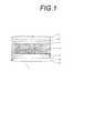
- thermoelectric conversion element of this invention It is a figure which shows typically an example of the thermoelectric conversion element of this invention.
- the arrows in FIG. 1 indicate the direction of the temperature difference applied when the element is used.
- the arrows in FIG. 2 indicate the direction of the temperature difference applied when the element is used.
- thermoelectric conversion element of the present invention uses a thermoelectric conversion material containing a polythiophene polymer having a specific structure, a carbon nanotube, and a non-conjugated polymer in a thermoelectric conversion layer. First, the thermoelectric conversion material and its components used in the present invention will be described.
- thermoelectric conversion material The thermoelectric conversion performance of the thermoelectric conversion material or the thermoelectric conversion element can be measured by a figure of merit ZT represented by the following formula (A).
- ZT figure of merit
- factors other than electrical conductivity greatly affect thermoelectric conversion performance, so it is actually unknown whether a material with high conductivity generally functions effectively as a thermoelectric conversion material. It is.
- the thermoelectric conversion material of the present invention can realize high conductivity without lowering the thermoelectromotive force, and has high thermoelectric conversion performance sufficient for use as a thermoelectric conversion material, as demonstrated in Examples described later.
- the carbon nanotube includes a single-walled CNT in which a single carbon film (graphene sheet) is wound in a cylindrical shape, a double-walled CNT in which two graphene sheets are wound in a concentric shape, and a plurality of graphenes There is a multilayer CNT in which sheets are wound concentrically.
- single-walled CNTs, double-walled CNTs, and multilayered CNTs may be used alone, or two or more kinds may be used in combination.
- Single-walled CNTs may be semiconducting or metallic, and both may be used in combination.
- the CNT may contain a metal or the like, or may contain a molecule such as fullerene.
- the thermoelectric conversion material of the present invention may contain nanocarbons such as carbon nanohorns, carbon nanocoils, and carbon nanobeads in addition to CNTs.
- CNT can be produced by an arc discharge method, a chemical vapor deposition method (hereinafter referred to as a CVD method), a laser ablation method, or the like.
- the CNT used in the present invention may be obtained by any method, but is preferably obtained by an arc discharge method and a CVD method.
- a CVD method chemical vapor deposition method
- fullerene, graphite, and amorphous carbon are produced as by-products at the same time, and catalytic metals such as nickel, iron, cobalt, and yttrium remain. In order to remove these impurities, purification is preferably performed.
- the method for purifying CNTs is not particularly limited, but acid treatment with nitric acid, sulfuric acid, etc., and ultrasonic treatment are effective for removing impurities. In addition, it is more preferable to perform separation and removal using a filter from the viewpoint of improving purity.
- CNT can be used as it is.
- CNT since CNT is generally produced in a string shape, it may be cut into a desired length depending on the application.
- CNTs can be cut into short fibers by acid treatment with nitric acid, sulfuric acid or the like, ultrasonic treatment, freeze pulverization method or the like.
- not only cut CNTs but also CNTs produced in the form of short fibers in advance can be used in the same manner.
- Such short fibrous CNTs for example, form a catalytic metal such as iron or cobalt on a substrate, and thermally decompose the carbon compound at 700 to 900 ° C.
- the short fiber CNTs thus produced can be taken out by a method such as peeling off from the substrate.
- the short fibrous CNTs can be obtained by supporting a catalytic metal on a porous support such as porous silicon or an anodic oxide film of alumina and growing the CNTs on the surface by the CVD method.
- a catalytic metal on a porous support such as porous silicon or an anodic oxide film of alumina
- the CVD method Using oriented molecules such as iron phthalocyanine containing a catalytic metal in the molecule as a raw material and producing CNTs on a substrate by performing CVD in an argon / hydrogen gas flow, producing oriented short fiber CNTs Can do.
- short fiber CNTs oriented on the SiC single crystal surface can be obtained by an epitaxial growth method.
- the average length of the CNTs used in the present invention is not particularly limited, but from the viewpoints of manufacturability, film formability, conductivity, etc., the average length of the CNTs is preferably 0.01 ⁇ m or more and 1000 ⁇ m or less. More preferably, it is 1 ⁇ m or more and 100 ⁇ m or less.
- the diameter of the CNT used in the present invention is not particularly limited, but from the viewpoint of durability, transparency, film formability, conductivity, etc., the diameter of the CNT is preferably 0.4 nm or more and 100 nm or less, more preferably 50 nm. Hereinafter, it is more preferably 15 nm or less.
- the content of CNT in the thermoelectric conversion material is preferably 10 to 60% by mass, more preferably 10 to 50% by mass, and particularly preferably 20 to 50% by mass in the total solid content.
- the thermoelectric conversion material of the present invention is excellent in CNT dispersibility, and good film formability can be obtained even if the CNT content is high.
- the polythiophene polymer used for the thermoelectric conversion material is a polymer having an alkyl-substituted thiophene structure represented by the following general formula (1) as a repeating unit and having a main chain composed of the repeating unit, and the polymer side chain R is a polymer. It is a polythiophene polymer having a regiorandom arrangement with respect to the main chain.
- the polythiophene polymer has a conjugated molecular structure and functions as a conductive polymer.
- R represents an alkyl group having 1 to 20 carbon atoms.
- R may be a linear alkyl group or a branched alkyl group. Specifically, methyl, ethyl, propyl, butyl, pentyl, hexyl, heptyl, octyl, nonyl, decyl, undecyl, dodecyl, tridecyl, tetradecyl as linear alkyl groups Group, pentadecyl group, hexadecyl group, heptadecyl group, octadecyl group, nonadecyl group, eicosyl group, and branched alkyl groups such as isopropyl group, isobutyl group, s-butyl group, t-butyl group, 2-ethylhexyl group, 2- Examples thereof include a methylbutyl group, a 2-methylhexyl group,
- R preferably has 4 to 12 carbon atoms. Further, R is preferably a branched alkyl group, more preferably a branched alkyl group having 4 to 12 carbon atoms, a 2-ethylhexyl group, a 2-methylbutyl group, a 2-methylhexyl group, a 2-ethyloctyl group. And more preferably a 2-ethylhexyl group. As shown in the examples described later, when a branched alkyl group is introduced into R, the solubility of the polythiophene polymer and the dispersibility of the CNT in the thermoelectric conversion material are improved, and good film formability is obtained. It is done.
- the repeating unit represented by the general formula (1) Since the repeating unit represented by the general formula (1) has an asymmetric structure having an alkyl group R at the 3-position of the thiophene ring, the poly-alkyl-substituted thiophene obtained by polymerizing the repeating unit has a bond between repeating units. In this case, anisotropy occurs depending on the direction of bonding at the 2,5 positions of each thiophene ring. That is, the repeating unit represented by the general formula (1) is a compound in which the 2-positions of the thiophene ring are bonded to each other (HH conjugate: head-to-head), and a compound in which the 2-position and the 5-position are bonded (HT conjugate).
- a polymer containing such a bonding mode other than HT bonding is referred to as regiorandom (positional irregularity (array)).
- the proportion of these bonding modes contained in the polymer can be measured by nuclear magnetic resonance spectroscopy ( 1 H-NMR).
- the regiorandom type in which the side chain R of the polymer takes a position irregular arrangement with respect to the polymer main chain is used.
- the regiorandom type can be confirmed by measuring the HT (head to tail) bond ratio (%) with the total number of bonds being 100% in the bonds of the repeating units in the polymer.
- the HT bond ratio is determined by analyzing the position of the chemical shift of the hydrogen atom on the carbon atom directly bonded to the thiophene ring in the R bonded to the thiophene ring by 1 H-NMR (range of 2 to 4 ppm). Can be determined.
- a triplet signal is observed for a proton on a carbon atom directly connected to the thiophene ring, that is, a methylene proton
- the methylene proton is A multiplet signal is observed on the higher magnetic field side than the signal corresponding to the HT conjugate, and the HT binding ratio can be determined by comparing the integrated values of these signals.
- the value measured by this method is used as the HT bond ratio.
- the ratio of HT bonds in the polythiophene polymer is preferably less than 95%, more preferably 90% or less, and particularly preferably 80% or less.
- the lower limit of the HT bond ratio is not particularly limited, but 60% or more is practical.
- Polythiophene compounds are known to affect the conductivity and other physical properties of polymers due to differences in the manner of bonding of constituent monomers.
- the higher the ratio of HT bonds in a polythiophene compound the higher the planarity of the polymer main chain, and the easier it is to form a ⁇ - ⁇ stacking structure between polymers. It is preferred. For this reason, it has been common technical knowledge that it is preferable to use a regioregular polymer in order to improve physical properties such as conductivity.
- 2005-268582 also aim to improve desired performance by selectively using a regioregular polythiophene compound.
- the present invention is characterized by using a regiorandom polythiophene as an essential component of the composition instead of the regioregular type which is conventionally preferred.
- a regiorandom polythiophene polymer together with CNT, the solubility of the polythiophene in the composition is improved and the dispersibility of CNT is also improved.
- the number of repeating units represented by the general formula (1) is preferably about 4 to 2000.
- the molecular weight is preferably 5000 to 250,000 in terms of weight average molecular weight, more preferably 10,000 to 200,000, and further preferably 15,000 to 170,000.
- the weight average molecular weight can be measured by gel permeation chromatography (GPC).
- the polythiophene polymer used in the present invention may be a commercially available product, or may be synthesized by polymerizing raw material monomers by oxidative polymerization with an oxidizing agent added.
- the content of the polythiophene polymer in the thermoelectric conversion material is preferably 1 to 40% by mass, more preferably 5 to 40% by mass, and more preferably 5 to 30% by mass in the total solid content. Is more preferably 10 to 30% by mass.
- the content ratio of the polythiophene polymer and CNT in the solid content of the thermoelectric conversion material is preferably in the range of 1: 4 to 4: 1 on a mass basis, and is 1: 4. More preferably within the range of ⁇ 3: 1.
- thermoelectric conversion material excellent in both the solubility of the polythiophene polymer and the CNT dispersibility can be obtained.
- a film property can be realized, which is preferable.
- the impurity means a metal impurity containing at least one metal selected from Fe, Zn, and Ni.
- the impurities may include metal elements and ions of Fe, Zn, and Ni, and compounds and complexes containing them.
- the metal impurity may contain a metal other than Fe, Zn, and Ni.
- the concentration of the metal impurity in the polythiophene polymer is 1000 ppm or less, the solubility of polythiophene in the composition is improved, which is preferable. More preferably, it is 900 ppm or less, More preferably, it is 800 ppm or less. It is preferable that the lower limit of the impurity concentration is not as low as possible, but it is practical that it is 200 ppm or more.
- the concentration of the metal impurity in the polythiophene can be measured by ICP mass spectrometry (Inductively Coupled Plasma Mass Spectrometry) after thermally decomposing the polythiophene, and this measurement value is used in the present invention.
- the non-conjugated polymer used for the thermoelectric conversion material is a polymer compound that does not exhibit conductivity due to the conjugated structure of the polymer main chain.
- the polymer main chain is composed of a ring, a group, or an atom selected from an aromatic ring (carbocyclic aromatic ring, heteroaromatic ring), an ethynylene bond, an ethenylene bond, and a hetero atom having a lone pair. It is a polymer other than the polymer.
- the type is not particularly limited as long as it is a non-conjugated polymer that satisfies such conditions, and a conventionally known non-conjugated polymer can be used.
- a polymer compound obtained by polymerizing a compound selected from the group consisting of vinyl compounds, (meth) acrylate compounds, carbonate compounds, ester compounds, amide compounds, imide compounds, fluorine compounds and siloxane compounds is used.
- vinyl compounds include styrene, vinyl pyrrolidone, vinyl carbazole, vinyl pyridine, vinyl naphthalene, vinyl phenol, vinyl acetate, styrene sulfonic acid, vinyl alcohol, vinyl triphenylamine and other vinyl arylamines, vinyl tributylamine.
- Vinyltrialkylamines such as, and the like.
- (meth) acrylate compounds include alkyl group-containing hydrophobic acrylates such as methyl acrylate, ethyl acrylate, propyl acrylate, and butyl acrylate, 2-hydroxyethyl acrylate, 1-hydroxyethyl acrylate, 2-hydroxypropyl acrylate, Acrylate monomers such as hydroxyl group-containing acrylates such as 3-hydroxypropyl acrylate, 1-hydroxypropyl acrylate, 4-hydroxybutyl acrylate, 3-hydroxybutyl acrylate, 2-hydroxybutyl acrylate, 1-hydroxybutyl acrylate, etc. And methacrylate monomers in which the acryloyl group is replaced with a methacryloyl group.
- polymers obtained by polymerizing a carbonate compound include general-purpose polycarbonate composed of bisphenol A and phosgene, Iupizeta (trade name, manufactured by Mitsubishi Gas Chemical Co., Ltd.), Panlite (trade name, manufactured by Teijin Chemicals Ltd.), and the like. It is done.
- ester compound include lactic acid.
- polymers obtained by polymerizing ester compounds include Byron (trade name, manufactured by Toyobo Co., Ltd.) and the like.
- polymers obtained by polymerizing amide compounds include PA-100 (trade name, manufactured by T & K TOKA Corporation).
- polymer obtained by polymerizing an imide compound examples include Solpy 6,6-PI (trade name, manufactured by Solpy Kogyo Co., Ltd.).
- fluorine compound examples include vinylidene fluoride and vinyl fluoride.
- siloxane compound examples include diphenylsiloxane and phenylmethylsiloxane.
- the non-conjugated polymer may be a homopolymer or a copolymer. In the present invention, it is more preferable to use a polymer compound obtained by polymerizing a vinyl compound as the non-conjugated polymer.
- the content of the non-conjugated polymer in the thermoelectric conversion material is preferably 10 to 1500 parts by weight, more preferably 30 to 1200 parts by weight, with respect to 100 parts by weight of the polythiophene polymer. It is particularly preferable that it is in parts by mass.
- the non-conjugated polymer is preferably hydrophobic and more preferably has no hydrophilic group such as sulfonic acid or hydroxyl group in the molecule. Further, a non-conjugated polymer having a solubility parameter (SP value) of 11 or less is preferable.
- SP value solubility parameter
- non-conjugated polymers having an SP value of 11 or less include polyvinyl compounds such as polystyrene, polyvinyl naphthalene, and polyvinyl acetate, poly (meth) acrylates such as polymethyl acrylate, ethyl acrylate, propyl acrylate, and butyl acrylate, polyester compounds, and polycarbonate. , Polyvinylidene fluoride and the like are preferable, and polystyrene, polyvinyl naphthalene, polymethyl acrylate, and polycarbonate are more preferable.
- the total solid content concentration of the solid content concentrations of CNT, polythiophene polymer and non-conjugated polymer is preferably 3 to 20% by mass, and preferably 4 to 15% by mass. Is more preferable.
- the thermoelectric conversion material of the present invention even when the solid content concentration in the material is high, the dispersibility of CNTs is excellent and good film formability is obtained.
- thermoelectric conversion material of the present invention preferably contains a solvent in addition to the above-described CNT, polythiophene polymer and non-conjugated polymer.
- the thermoelectric conversion material of the present invention is more preferably a CNT dispersion in which a polythiophene component is dissolved in a solvent and CNTs are dispersed.
- the solvent should just be able to disperse
- organic solvents such as alcohol, chloroform, aprotic polar solvents such as DMF, NMP, DMSO, chlorobenzene, dichlorobenzene, benzene, toluene, xylene, mesitylene, tetralin, tetramethylbenzene, pyridine
- aromatic solvents such as cyclohexanone, ketone solvents such as acetone and methylethylkenton, ether solvents such as diethyl ether, THF, t-butyl methyl ether, dimethoxyethane and diglyme
- halogen solvents such as chloroform.
- aprotic polar solvents such as DMF and NMP
- aromatic solvents such as dichlorobenzene, xylene, mesitylene, tetralin and tetramethylbenzene
- ether solvents such as THF.
- the solvent is preferably degassed in advance.
- the dissolved oxygen concentration in the solvent is preferably 10 ppm or less.
- Examples of the degassing method include a method of irradiating ultrasonic waves under reduced pressure, a method of bubbling an inert gas such as argon, and the like.
- the solvent is preferably dehydrated in advance.
- the amount of water in the solvent is preferably 1000 ppm or less, and more preferably 100 ppm or less.
- a dehydration method a known method such as a method using molecular sieve or distillation can be used.
- the amount of the solvent in the thermoelectric conversion material is preferably 90 to 99.5% by mass, more preferably 90 to 97% by mass, and 92.5 to 96% by mass with respect to the total amount of the thermoelectric conversion material. More preferably.
- the thermoelectric conversion material of the present invention may contain a dopant as appropriate.
- the dopant is a compound doped into the polythiophene polymer which is a conductive polymer, and the polythiophene is doped with a positive charge (p-type doping) by protonating the polythiophene or removing electrons from the ⁇ -conjugated system of the polythiophene. Anything can be used. Specifically, the following onium salt compounds, oxidizing agents, acidic compounds, electron acceptor compounds and the like can be used.
- Onium salt compound used as a dopant is preferably a compound (acid generator, acid precursor) that generates an acid upon application of energy such as irradiation of active energy rays (radiation, electromagnetic waves, etc.) or application of heat.
- onium salt compounds include sulfonium salts, iodonium salts, ammonium salts, carbonium salts, phosphonium salts, and the like.
- sulfonium salts, iodonium salts, ammonium salts and carbonium salts are preferable, sulfonium salts, iodonium salts and carbonium salts are more preferable, and sulfonium salts and iodonium salts are particularly preferable.
- anion moiety constituting the salt include a strong acid counter anion.
- Examples of the acidic compound include polyphosphoric acid, hydroxy compound, carboxy compound, or sulfonic acid compound, protonic acid (HF, HCl, HNO 3 , H 2 SO 4 , HClO 4 , FSO 3 H, CISO 3 H, CF 3) SO 3 H, various organic acids, amino acids, etc.).
- Examples of electron acceptor compounds include TCNQ (tetracyanoquinodimethane), tetrafluorotetracyanoquinodimethane, halogenated tetracyanoquinodimethane, 1,1-dicyanovinylene, 1,1,2-tricyanovinylene, benzoquinone.
- Polyphosphoric acid- Polyphosphoric acid includes diphosphoric acid, pyrophosphoric acid, triphosphoric acid, tetraphosphoric acid, metaphosphoric acid and polyphosphoric acid, and salts thereof. A mixture thereof may be used.
- the polyphosphoric acid is preferably diphosphoric acid, pyrophosphoric acid, triphosphoric acid, or polyphosphoric acid, and more preferably polyphosphoric acid.
- Polyphosphoric acid can be synthesized by heating H 3 PO 4 with sufficient P 4 O 10 (anhydrous phosphoric acid) or by heating H 3 PO 4 to remove water.
- the hydroxy compound may be a compound having at least one hydroxyl group, and preferably has a phenolic hydroxyl group.
- a compound represented by the following general formula (VIII) is preferable.
- R represents a sulfo group, a halogen atom, an alkyl group, an aryl group, a carboxy group, or an alkoxycarbonyl group
- n represents 1 to 6
- m represents 0 to 5.
- R is preferably a sulfo group, an alkyl group, an aryl group, a carboxy group, or an alkoxycarbonyl group, and more preferably a sulfo group.
- n is preferably 1 to 5, more preferably 1 to 4, and still more preferably 1 to 3.
- m is 0 to 5, preferably 0 to 4, and more preferably 0 to 3.
- the carboxy compound may be a compound having at least one carboxy group, and a compound represented by the following general formula (IX) or (X) is preferable.
- A represents a divalent linking group.
- the divalent linking group is preferably a combination of an alkylene group, an arylene group or an alkenylene group and an oxygen atom, a sulfur atom or a nitrogen atom, and more preferably a combination of an alkylene group or an arylene group and an oxygen atom or a sulfur atom. preferable.
- the divalent linking group is a combination of an alkylene group and a sulfur atom
- the compound also corresponds to a thioether compound.
- the use of such a thioether compound is also suitable.
- the divalent linking group represented by A includes an alkylene group, the alkylene group may have a substituent. As the substituent, an alkyl group is preferable, and a carboxy group is more preferable as a substituent.
- R represents a sulfo group, a halogen atom, an alkyl group, an aryl group, a hydroxy group, or an alkoxycarbonyl group
- n represents 1 to 6
- m represents 0 to 5.
- R is preferably a sulfo group, an alkyl group, an aryl group, a hydroxy group or an alkoxycarbonyl group, more preferably a sulfo group or an alkoxycarbonyl group.
- n is preferably 1 to 5, more preferably 1 to 4, and still more preferably 1 to 3.
- m is 0 to 5, preferably 0 to 4, and more preferably 0 to 3.
- the sulfonic acid compound is a compound having at least one sulfo group, and a compound having two or more sulfo groups is preferable.
- the sulfonic acid compound is preferably one substituted with an aryl group or an alkyl group, and more preferably one substituted with an aryl group.
- the compound which has a sulfo group as a substituent is also suitable.
- the amount of the dopant used is preferably 5 parts by mass or more, more preferably 5 to 40 parts by mass, more preferably 5 to 30 parts by mass with respect to 100 parts by mass of the polythiophene polymer from the viewpoint of the doping effect. More preferably.
- thermoelectric conversion material of the present invention may contain other components in addition to the above components.
- a surfactant can be contained.
- lithium hydroxide, ammonium persulfate, an ultraviolet absorber, a polymerization inhibitor, a leveling additive, a matting agent and the like can be contained.
- inorganic fine particles such as silica, titania and zirconia, (crosslinked) polymer fine particles, silane coupling agents, waxes and the like can be contained.
- silica and titania is preferable from the viewpoint of improving dispersibility due to an increase in viscosity.
- an antioxidant, a light stabilizer, a heat stabilizer, a plasticizer, and the like may be appropriately contained.
- the content of these components is preferably about 0.1 to 5% by mass with respect to the total mass of the thermoelectric conversion material.
- thermoelectric conversion material of the present invention can be prepared by mixing the above components.
- CNT, polythiophene polymer and non-conjugated polymer are added to a solvent and mixed, and each component is dissolved or dispersed.
- the order of addition and mixing of each component is not particularly limited, but it is preferable to add a predetermined amount of a polythiophene polymer in a solvent in advance and then add and disperse a predetermined amount of CNT, and then add a non-conjugated polymer.
- a dispersion method such as mechanical homogenizer method, jaw crusher method, ultracentrifugation method, cutting mill method, automatic mortar method, disk mill method, ball mill method, ultrasonic homogenizer method, ultrahigh pressure homogenizer method, roll mill dispersion method, etc. Can do. Further, if necessary, two or more of these methods may be used in combination.
- a preferred combination of dispersion methods is a mechanical homogenizer method and an ultrasonic dispersion method, an ultrasonic homogenizer method and a roll mill dispersion method, an ultra-high pressure homogenizer method and a roll mill dispersion method, more preferably an ultrasonic homogenizer method and a roll mill dispersion method, and an ultra-high pressure.
- a homogenizer method and a roll mill dispersion method As the order of combination, it is preferable to perform a roll mill dispersion method after dispersion by an ultrasonic homogenizer method or an ultrahigh pressure homogenizer method. By performing in this order, after the viscosity is increased by the ultrasonic homogenizer method or the ultrahigh pressure homogenizer method, the CNTs can be further dispersed by the roll mill dispersion method.
- thermoelectric conversion material can be prepared in the air, it is preferably performed in an inert atmosphere.
- An inert atmosphere refers to a state where the oxygen concentration is lower than the atmospheric concentration.
- the atmosphere has an oxygen concentration of 10% or less.
- Examples of the method for making the inert atmosphere include a method of substituting the atmosphere with a gas such as nitrogen or argon, which is preferably used.
- the temperature during preparation is preferably in the range of 0 ° C to 50 ° C.
- CNTs contained in the obtained thermoelectric conversion material may contain defective CNTs. Such CNT defects are preferably reduced in order to reduce the conductivity of the thermoelectric conversion material.
- the amount of CNT defects in the thermoelectric conversion material can be estimated by the ratio G / D of the G-band and D-band of the Raman spectrum. It can be estimated that the higher the G / D ratio, the less the amount of defects, the CNT material.
- the G / D ratio of the thermoelectric conversion material is preferably 10 or more, and more preferably 30 or more.
- thermoelectric conversion element The thermoelectric conversion element of this invention should just be formed using the thermoelectric conversion material of this invention for a thermoelectric conversion layer.
- the thermoelectric conversion layer is not particularly limited as long as the thermoelectric conversion layer is obtained by molding the thermoelectric conversion material on a substrate, and the thermoelectric conversion material of the present invention has good CNT dispersibility. Therefore, the thermoelectric conversion layer can be formed by coating and forming a film on the substrate.
- the film forming method is not particularly limited. For example, known coating methods such as spin coating, extrusion die coating, blade coating, bar coating, screen printing, stencil printing, roll coating, curtain coating, spray coating, dip coating, and inkjet method. Can be used. After application, a drying process is performed as necessary. For example, the solvent can be volatilized and dried by blowing hot air.
- the substrate can be a substrate made of glass, transparent ceramics, metal, plastic film or the like.
- plastic film that can be used in the present invention include polyethylene terephthalate, polyethylene isophthalate, polyethylene naphthalate, polybutylene terephthalate, poly (1,4-cyclohexylenedimethylene terephthalate), polyethylene-2,6-phthalene dicarboxylate.
- Polycycloolefin films such as rate, polyester films such as polyester films of bisphenol A and iso and terephthalic acid, product names ZEONOR film (manufactured by Nippon Zeon), ARTON film (manufactured by JSR), Sumilite FS1700 (manufactured by Sumitomo Bakelite) , Product name Kapton (made by Toray DuPont), Apical (made by Kaneka), Ubilex (made by Ube Industries), Pomilan (made by Arakawa Chemical Co.), Polyester such as Sose (made by Teijin Chemicals), Elmec (made by Kaneka), polyether ether ketone film such as product name Sumilite FS1100 (made by Sumitomo Bakelite), polyphenyl such as product name Torelina (made by Toray Industries, Inc.) Examples thereof include a sulfide film.
- polyethylene terephthalate polyethylene naphthalate
- various polyimides polycarbonate films, and the like are preferable from the viewpoints of availability, preferably heat resistance of 100 ° C. or higher, economy, and effects.
- a base material in which various electrode materials are provided on the pressure contact surface with the thermoelectric conversion layer.
- This electrode material includes transparent electrodes such as ITO and ZnO, metal electrodes such as silver, copper, gold, aluminum, chromium and nickel, carbon materials such as CNT and graphene, organic materials such as PEDOT / PSS, silver and carbon, etc.
- a conductive paste in which conductive fine particles are dispersed, a conductive paste containing metal nanowires such as silver, copper, and aluminum can be used.
- thermoelectric conversion element of this invention should just have a thermoelectric conversion layer using the thermoelectric conversion material of this invention, and it does not specifically limit about the structure.
- it is an element provided with a base material (substrate) and a thermoelectric conversion layer provided on the base material, more preferably an element further having an electrode for electrically connecting them, more preferably
- the element includes a base material and a pair of electrodes on the base material, and a thermoelectric conversion layer is disposed between the pair of electrodes.
- Examples of the structure of the thermoelectric conversion element of the present invention include the structure of the element (1) shown in FIG. 1 and the element (2) shown in FIG. The element (1) shown in FIG.
- 1 includes a pair of electrodes including a first electrode (13) and a second electrode (15) on a first substrate (12), and the electrode of the present invention between the electrodes.
- An element comprising a layer (14) of thermoelectric conversion material.
- the second electrode (15) is disposed on the surface of the second base material (16), and the first base material (12) and the second base material (16) are arranged on the outer sides of the metal facing each other. Plates (11 and 17) are arranged.
- a first electrode (23) and a second electrode (25) are disposed on a first base material (22), and a thermoelectric conversion material layer ( 24) is provided.
- arrows indicate the direction of the temperature difference when the thermoelectric conversion element is used.
- thermoelectric conversion material of the present invention is provided in the form of a film (film) on a base material, and the base material functions as the first base material (12, 22).
- the above-mentioned various electrode materials are provided on the substrate surface (pressure contact surface with the thermoelectric conversion layer), and a thermoelectric conversion layer formed using the thermoelectric conversion material of the present invention is provided thereon. It is preferable.
- thermoelectric conversion layer one surface is covered with a base material.
- a base material (second base material (16, 26)) is preferably pressure-bonded from the viewpoint of protecting the film.
- the pressure bonding between the second base material and the thermoelectric conversion layer is preferably performed by heating to about 100 ° C. to 200 ° C. from the viewpoint of improving adhesion.
- the thickness of the thermoelectric conversion layer is preferably 0.1 ⁇ m to 1000 ⁇ m, more preferably 1 ⁇ m to 100 ⁇ m. By setting the film thickness within this range, it is easy to impart a temperature difference and increase in resistance within the film can be prevented.
- the thicknesses of the first and second base materials are preferably 30 to 3000 ⁇ m, more preferably 50 to 1000 ⁇ m, still more preferably 100 to 1000 ⁇ m, and particularly preferably 200 to 800 ⁇ m from the viewpoints of handleability and durability. It is. By setting the thickness of the base material within this range, the thermal conductivity does not decrease, and the film (thermoelectric conversion layer) is not easily damaged by an external impact.
- thermoelectric conversion layer in a thermoelectric conversion element, compared to a photoelectric conversion element such as an organic thin film solar cell element, the thermoelectric conversion layer may be applied and formed in one organic layer, and the element can be easily produced.
- thermoelectric conversion material of the present invention it is possible to increase the film thickness by about 100 to 1000 times compared with the element for organic thin film solar cells, and the chemical stability against oxygen and moisture in the air is improved. To do.
- thermoelectric conversion element of the present invention can be suitably used as a power generation element of an article for thermoelectric power generation.
- power generators such as hot spring thermal generators, solar thermal generators, waste heat generators, wristwatch power supplies, semiconductors It can be suitably used for applications such as a drive power source and a small sensor power source.
- Polythiophene 1 (Regiorandom, HT bond ratio: ⁇ 90%) Polythiophene 1 (Regular, HT bond ratio: ⁇ 95%) Polythiophene 2 (Regiorandom, HT bond ratio: ⁇ 90%) Polythiophene 2 (Regular, HT bond ratio: ⁇ 95%) Polythiophene 3 (Regiorandom, HT bond ratio: ⁇ 90%) Polythiophene 4 (Regiorandom, HT bond ratio: ⁇ 90%) Polythiophene 5 (Regiorandom, HT bond ratio: 78%) Polythiophene 6 (Regiorandom, HT bond ratio: 72%)
- Polythiophenes 1 to 4 were all manufactured by Aldrich, and polythiophenes 5 to 6 were synthesized as follows.
- the HT bond ratio of the polythiophene polymer was confirmed by analyzing the integrated value of the signal of the thienyl group-bound methylene proton in the methylene region in 1 H-NMR.
- the structures of the used polythiophenes 1 to 6 are shown below.
- Polythiophene 5 was synthesized by the following method. [Synthesis of 3- (2-ethylhexyl) thiophene monomer A] Under a nitrogen stream, 3.27 g (20 mmol) of 3-bromothiophene was dissolved in 20 mL of dehydrated THF and cooled to 0 ° C. To the solution, 245 mL (24 mmol) of 2-ethylhexylmagnesium bromide (1M diethyl ether solution) was added dropwise. After completion of the addition, the mixture was heated to reflux for 3 hours.
- Polythiophene 6 was synthesized by the following method. [Synthesis of 3- (isobutyl) thiophene monomer B] Under a nitrogen stream, 3.27 g (20 mmol) of 3-bromothiophene was dissolved in 20 mL of dehydrated THF and cooled to 0 ° C. To that solution, 245 mL (24 mmol) of isobutylmagnesium bromide (1M THF / 2M diethyl ether solution) was added dropwise, and after completion of the addition, the mixture was heated to reflux for 3 hours.
- the weight average molecular weight of each polythiophene polymer was calculated
- Apparatus “Alliance GPC2000 (Waters)” Column: TSKgel GMH 6 -HT ⁇ 2 + TSKgel GMH 6 -HTL ⁇ 2 (Both 7.5 mm ID ⁇ 30 cm, manufactured by Tosoh Corporation) Column temperature: 140 ° C Detector: Differential refractometer Mobile phase: o-dichlorobenzene
- Example 1-1 Preparation of carbon nanotube-dispersed paste Add 320 ml of o-dichlorobenzene to 320 mg of the above polythiophene 1 (Regio Random), and use an ultrasonic cleaner “US-2” (produced by Iuchi Seieido Co., Ltd., output 120 W, indirect irradiation). Thus, a polythiophene solution 1-1 was produced. The solubility of polythiophene was evaluated by the following method.
- ASP-100F manufactured by Hanwha Nanotech, purity 95%) as a single-walled carbon nanotube was added to the solution 1-1, and an ultrasonic homogenizer VC-750 (manufactured by SONICS & MATERIALS. Inc., tapered microchip (probe diameter 6. 5 mm), power output 40 W, direct irradiation, duty ratio 50%), and ultrasonically dispersed at 30 ° C. for 30 minutes.
- ultrasonic cleaning machine “US-2” manufactured by Iuchi Seieido Co., Ltd., output 120 W, indirect irradiation was used for ultrasonic dispersion at 30 ° C.
- Carbon nanotube dispersion paste 1-1 was produced by stirring with an apparatus ARE-250 (manufactured by Sinky) at a rotational speed of 2,000 rpm and a stirring time of 5 minutes.
- the solid content concentration in the paste was 4.1% by mass, and the CNT content in the solid content was 28.5% by mass.
- the dispersibility of CNTs was evaluated by the following method.
- thermoelectric conversion layer 1-1 The carbon nanotube dispersion paste 1-1 prepared above was formed on a substrate to form a thermoelectric conversion layer. Specifically, an ultrasonic cleaning in isopropyl alcohol followed by UV-ozone treatment for 10 minutes on a glass substrate having a thickness of 1.1 mm has an opening 13 ⁇ 13 mm formed by laser processing and has a thickness of 2 mm. The metal mask was put on. Next, after injecting the carbon nanotube dispersion paste 1-1 prepared above into the opening, the metal mask is removed, and then the glass substrate is heated and dried on a hot plate at 80 ° C. to form the thermoelectric conversion layer 1-1. Fabricated and evaluated for its film formability, conductivity, and thermoelectric performance.
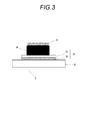
- thermoelectric conversion element shown in FIG. 3 was produced using the carbon nanotube dispersion paste 1-1 prepared above. More specifically, after ultrasonic cleaning in isopropyl alcohol, a metal mask having an opening of 20 ⁇ 20 mm formed by etching on a glass substrate (32) having a size of 40 ⁇ 50 mm and a thickness of 1.1 m is used. Electrode 1 (33) was formed by depositing (30 and 31) a chromium film having a thickness of 100 nm and then a gold film having a thickness of 100 nm by plating.
- thermoelectric conversion layer 1-1 was formed on the electrode 1 by heating and drying on the plate.
- a conductive paste dotite D-550 (manufactured by Fujikura Kasei, silver paste) is applied by screen printing to form an electrode 2 (35) on the thermoelectric conversion layer 1-1, and the thermoelectric conversion element 1- 1 (3) was produced and its thermoelectromotive force was evaluated.
- Test Method Test methods for characteristics and the like in the examples and comparative examples of the present invention are as follows.
- the polythiophene solubility was evaluated visually by the following four criteria at the time of dissolution in a solvent. 1: The dissolution time in the solvent was shorter than 1 minute. 2: The dissolution time in the solvent was in the range of 1 minute to less than 5 minutes. 3: The dissolution time in the solvent was in the range of 5 minutes to less than 15 minutes. 4: The dissolution time in the solvent was 15 minutes or more.
- CNT dispersibility The CNT dispersibility was evaluated by visual observation and the following four-stage criteria after dropping the paste on a slide glass and placing a cover glass. 1: No black aggregate was observed. 2: Black aggregates having a size of less than 0.5 mm were observed. 3: Black aggregates having a size of 0.5 mm or more and less than 1 mm were observed. 4: The amount of aggregates exceeding the standard 3 was observed.
- thermoelectric conversion layer is 1.5 times or less compared to the opening of the metal mask.
- the size of the thermoelectric conversion layer is larger than 1.5 times and 2.0 times that of the opening of the metal mask.
- the following 3 The size of the thermoelectric conversion layer is 2.0 times larger than the opening of the metal mask
- thermoelectromotive force of the thermoelectric conversion element is the digital multimeter R6581 (manufactured by Advantest), which is a voltage difference generated between the electrode 1 and the electrode 2 when the glass substrate of the thermoelectric conversion element is heated with a hot plate having a surface temperature of 80 ° C. Measured with
- Examples 1-2 to 1-5 Example except that polythiophene 1 used in Example 1-1 was changed to the same amount of polythiophene 2 (Regiorandom), polythiophene 3 (Regiorandom), polythiophene 5 (Regiorandom), or polythiophene 6 (Regiorandom)
- polythiophene 1 used in Example 1-1 was changed to the same amount of polythiophene 2 (Regiorandom), polythiophene 3 (Regiorandom), polythiophene 5 (Regiorandom), or polythiophene 6 (Regiorandom)
- a thermoelectric conversion layer and a thermoelectric conversion element were produced and their characteristics were evaluated. The results are shown in Table 1-1.
- thermoelectric conversion layer and the thermoelectric conversion element were obtained in the same manner as in Example 1-1 except that the regiorandom polythiophene 1 used in Example 1-1 was changed to regioregular polythiophene 1 or regioregular polythiophene 2. It was prepared and its characteristics were evaluated. The results are shown in Table 1-1.
- thermoelectric conversion layer and a thermoelectric conversion element were produced in the same manner as in Example 1-1 except that the carbon nanotube dispersion paste 1-1 used in Example 1-1 was changed to the following comparative carbon nanotube dispersion paste. The characteristics were evaluated. The results are shown in Table 1-1.
- thermoelectric conversion layers containing regiorandom polythiophene, CNT, and non-conjugated polymer are polythiophene solubility, CNT dispersibility, and film formation.
- the electrical conductivity, thermoelectric performance (PF) and thermoelectromotive force were also excellent.
- Examples 1-4 and 1-5 using a regiorandom polythiophene having a branched alkyl group in the side chain were particularly excellent in polythiophene solubility and CNT dispersibility.
- Comparative Examples 1-1 and 1-2 using regioregular polythiophene the polythiophene solubility and CNT dispersibility were worse than those in Examples, and the conductivity was greatly reduced. Moreover, since the film formability was reduced and the film thickness of the thermoelectric conversion element was reduced accordingly, the temperature difference was reduced and the thermoelectromotive force was also reduced. As a result, thermoelectric performance (PF) also decreased. Further, Comparative Example 1-3 containing no non-conjugated polymer was very poor in film formability and could not maintain the pattern after printing. Therefore, a thermoelectric conversion layer could not be formed and performance evaluation could not be performed.
- thermoelectric conversion layer and a thermoelectric conversion element were produced in the same manner as in Example 1-4 except that o-dichlorobenzene was changed to the same amount of mesitylene or tetralin in Example 1-4, and the characteristics thereof were evaluated. The results are shown in Table 1-2.
- Examples 1-6 and 1-7 using mesitylene or tetralin as a solvent showed excellent results as in Example 1-4, and showed thermoelectric performance (PF) and heat The electromotive force was even better.
- Example 2-1 A thermoelectric conversion layer and a thermoelectric conversion element were produced in the same manner as in Example 1-1 except that the polythiophene used in Example 1-1 was changed to the same amount of polythiophene 5 (Regiorandom), and the characteristics were evaluated. did.
- the polythiophene 5 used was analyzed for Fe content by the following ICP mass spectrometry. The results are shown in Table 2.
- the amount of Fe impurities in polythiophene was quantified by ICP mass spectrometry using “ICP-MS Agilent 7500cs” (manufactured by Agilent).
- the Fe element from the sample was weighed in a crucible and then subjected to an ashing operation. After concentrated acid was added and a superheated concentration operation was performed, diluted acid was added and recovered. Further, this solution was further diluted with dilute acid (addition of internal standard) to quantify Fe.
- Example 2-1 using polythiophene with a small amount of metal impurities was excellent in polythiophene solubility, CNT dispersibility, and film formability. Moreover, thermoelectric performance (PF) and thermoelectromotive force were also high.
- Example 3-1 Add 40 ml of o-dichlorobenzene to 480 mg of polythiophene 2 (Regio Random), and use ultrasonic cleaner “US-2” (manufactured by Inoue Seieido Co., Ltd., output 120 W, indirect irradiation) at 40 ° C. for 10 minutes. Under the conditions described above, a polythiophene solution 3-1 was prepared. Next, 960 mg of ASP-100F (manufactured by Hanwha Nanotech, purity 95%) as a single-walled carbon nanotube was added to the solution 3-1, and an ultrasonic homogenizer VC-750 (manufactured by SONICS & MATERIALS.
- Ultrasonic homogenizer VC-750 manufactured by SONICS & MATERIALS.
- Examples 3-2 to 3-4 The carbon nanotube-dispersed paste 3 was prepared in the same manner as in Example 3-1, except that the polythiophene 2 was changed to the same amount of polythiophene 3 (Regiorandom), polythiophene 4 (Regiorandom), or polythiophene 5 (Regiorandom). -2 to 3-4 were produced.
- Example 3-5 Polythiophene 3 (Regio Random) 640 mg, o-dichlorobenzene 40 ml was added, and using an ultrasonic cleaner “US-2” (manufactured by Iuchi Seieido Co., Ltd., output 120 W, indirect irradiation), polythiophene solution 3-5 was made.
- an ultrasonic cleaner VC-750 manufactured by Hanwha Nanotech, purity 95%) as a single-walled carbon nanotube was added to the solution 3-5, and an ultrasonic homogenizer VC-750 (manufactured by SONICS & MATERIALS.
- Carbon nanotube dispersion paste 3-5 was prepared by stirring with an apparatus ARE-250 (manufactured by Sinky) at a rotation speed of 2,000 rpm and a stirring time of 15 minutes.
- the solid content concentration in this paste was 11.9% by mass, and the CNT content in the solid content was 18.1% by mass.
- Example 3-6 A carbon nanotube dispersion paste 3-6 was produced in the same manner as in Example 3-5, except that the polythiophene 3 was changed to the same amount of polythiophene 5 (Regiorandom).
- Comparative Example 3-1 A comparative carbon nanotube dispersion paste 3-1 was prepared in the same manner as in Example 3-1, except that polythiophene 2 (residue random) was changed to polythiophene 2 (residual regular).
- thermoelectric conversion layer and a thermoelectric conversion element were produced in the same manner as in Example 1-1 except that the carbon nanotube dispersion paste 1-1 used in Example 1-1 was changed to the pastes produced above. Characteristics were evaluated. The results are shown in Table 3. In addition, the solid content concentration in Table 3 indicates the solid content concentration in the carbon nanotube dispersion paste.
- Examples 3-1 to 3-6 having thermoelectric conversion layers containing regiorandom polythiophene, CNT, and non-conjugated polymer are excellent in CNT dispersibility and film formability and conductive. Rate, thermoelectric performance (PF) and thermoelectromotive force were also excellent.
- Examples 3-4 and 3-6 using regiorandom polythiophene having a branched alkyl group in the side chain are particularly excellent in polythiophene solubility and CNT dispersibility, and have good dispersibility even when the solid content concentration of CNT is high. Obtained.
- Comparative Example 3-1 which uses regioregular polythiophene, the thiophene solubility and the CNT dispersibility were greatly reduced, and the film formability was poor. Moreover, the roughness of the thermoelectric conversion layer surface was large due to the aggregates of CNTs, and performance evaluation could not be performed.
- Example 4-1 Polythiophene solution 4-1 was added to 960 mg of polythiophene 5 (Regiorandom) by adding 40 ml of o-dichlorobenzene and using an ultrasonic cleaner “US-2” (manufactured by Inoue Seiei Co., Ltd., output 120 W, indirect irradiation). Was made. Next, 1.28 g of ASP-100F (manufactured by Hanwha Nanotech, purity 95%) as single-walled carbon nanotubes was added to the solution 4-1, and an ultrasonic homogenizer VC-750 (manufactured by SONICS & MATERIALS.
- Dispersion 4-1 1.5 g of polystyrene (manufactured by Wako Pure Chemical Industries, Ltd.) having a degree of polymerization of 2,000 as a non-conjugated polymer is added to Dispersion 4-1, and dissolved in a 50 ° C. warm bath, followed by self-revolving stirring.
- the carbon nanotube dispersion paste 4-1 was produced by stirring with an apparatus ARE-250 (manufactured by Sinky) at a rotation speed of 2,200 rpm and a stirring time of 20 minutes.
- the solid content concentration in the paste was 6.7% by mass, and the CNT content in the solid content was 34% by mass.
- Example 4-2 A carbon nanotube-dispersed paste 4-2 was produced in the same manner as in Example 4-1, except that the polythiophene 5 was changed to the same amount of polythiophene 6 (Regiorandom).
- Example 4-3 Polythiophene solution 4-3 is added to 750 mg of polythiophene 5 (Regiorandom), using 40 ml of o-dichlorobenzene, and using an ultrasonic cleaner “US-2” (manufactured by Iuchi Seieido Co., Ltd., output 120 W, indirect irradiation).
- US-2 ultrasonic cleaner
- 1.5 g of ASP-100F manufactured by Hanwha Nanotech, purity 95%) as a single-walled carbon nanotube was added to the solution 4-3, and an ultrasonic homogenizer VC-750 (manufactured by SONICS & MATERIALS. Inc., tapered microchip (probe diameter).
- the carbon nanotube dispersion paste 4-3 was produced by stirring at ⁇ 250 (manufactured by Sinky) at a rotation speed of 2,200 rpm and a stirring time of 30 minutes.
- the solid content concentration in the paste was 5.5% by mass, and the CNT content in the solid content was 50% by mass.
- thermoelectric conversion layer and a thermoelectric conversion element were produced in the same manner as in Example 1-1 except that the carbon nanotube dispersion paste 1-1 used in Example 1-1 was changed to the pastes produced above. Characteristics were evaluated. The results are shown in Table 4.
- the CNT concentration in Table 4 indicates the CNT concentration in the total solid content.
- Examples 4-1 to 4-3 containing a regiorandom polythiophene having a branched alkyl in the side chain regiorandom polythiophene 5 having a 2-ethylhexyl group in the side chain was used.
- Examples 4-1 and 4-3 were particularly excellent in polythiophene solubility, CNT dispersibility, and film formability, and good dispersibility was obtained even when the CNT concentration was high.
- Example 5-1 Add 30 ml of o-dichlorobenzene to 30 mg of polythiophene 3 (Regiorandom), and use an ultrasonic washer “US-2” (manufactured by Inoue Seieido Co., Ltd., output 120 W, indirect irradiation) to obtain a polythiophene solution 5-1.
- US-2 ultrasonic washer
- 480 mg of KH SWCNT HP manufactured by KH Chemicals, purity 80%
- an ultrasonic homogenizer VC-750 SONICS & MATERIALS. Inc., tapered microchip (probe diameter 6.
- the precursor 5-1 was turned back 15 times using a three-roll mill disperser BR-100V (manufactured by Imex) under the condition of a rotation ratio of 1: 1.7: 2.9, and the carbon nanotube dispersion paste 5- 1 was prepared.
- the solid content concentration in this paste was measured, it was 4.8% by mass, and the CNT content in the solid content was 28.5% by mass.
- Example 5-2 A carbon nanotube dispersion paste 5-2 was produced in the same manner as in Example 5-1, except that the same amount of polythiophene 5 (Regiorandom) was used instead of polythiophene 3.
- Example 5-3 Carbon nanotube-dispersed paste in the same manner as in Example 5-2, except that the same amount of PC-Z type polycarbonate (manufactured by Teijin Chemicals Ltd., Panlite TS-2020) was used instead of poly (2-vinylnaphthalene) 5-3 was produced.
- PC-Z type polycarbonate manufactured by Teijin Chemicals Ltd., Panlite TS-2020
- thermoelectric conversion layer and a thermoelectric conversion element were produced in the same manner as in Example 1-1 except that the carbon nanotube dispersion paste 1-1 used in Example 1-1 was changed to the pastes produced above. Characteristics were evaluated. The results are shown in Table 5.
- the solid content concentration in Table 5 indicates the solid content concentration in the carbon nanotube dispersion paste.
- Examples 5-2 and 5-3 using regiorandom polythiophene having a branched alkyl group in the side chain were particularly excellent in CNT dispersibility.
- thermoelectric conversion element was produced using a polyethylene terephthalate (hereinafter referred to as PET) film produced below as a substrate.
- PET polyethylene terephthalate
- Adhesive Layer After both surfaces of the obtained support were subjected to corona discharge treatment under the condition of 730 J / m 2 , an adhesive layer coating liquid A having the following composition was applied to both surfaces at a coating amount of 4.4 cm 3 / m. 2 was applied by the bar coating method. And this was dried at 160 degreeC for 1 minute, and the laminated sheet (electric conductor) in which the contact bonding layer was formed on both surfaces of the support body was obtained by forming an contact bonding layer.
- Carbon nanotubes were prepared in the same manner as in Example 5-1, except that instead of poly (2-vinylnaphthalene), polystyrene having the same polymerization degree of 2,000 (manufactured by Wako Pure Chemical Industries, Ltd.) was used. Dispersion paste 6-1 was produced.
- thermoelectric conversion layer 6-1 was formed on the electrode 1 by heating and drying above.
- thermoelectric conversion element 6-1 a conductive paste dotite D-550 (manufactured by Fujikura Kasei, silver paste) is applied by screen printing to form an electrode 2 on the thermoelectric conversion layer 6-1 to produce a thermoelectric conversion element 6-1. did.
- a conductive paste dotite D-550 manufactured by Fujikura Kasei, silver paste
- a digital multimeter R6581 manufactured by Advantest
- Example 6-2 A carbon nanotube dispersion paste 6-2 was produced in the same manner as in Example 6-1 except that the same amount of polythiophene 5 (Regiorandom) was used instead of polythiophene 3. Subsequently, a thermoelectric conversion element 6-2 was produced in the same manner as in Example 6-1 except that the carbon nanotube dispersion paste 6-2 was used instead of the carbon nanotube dispersion paste 6-1.
- a voltage difference generated between the electrode 1 and the electrode 2 when the film substrate of the thermoelectric conversion element is heated with a hot plate having a surface temperature of 80 ° C. is measured with a digital multimeter R6581 (manufactured by Advantest), a voltage difference is generated. Confirmed.
- Electrode 1 (conductive paste)
Landscapes
- Chemical & Material Sciences (AREA)
- Chemical Kinetics & Catalysis (AREA)
- Medicinal Chemistry (AREA)
- Polymers & Plastics (AREA)
- Organic Chemistry (AREA)
- Health & Medical Sciences (AREA)
- Engineering & Computer Science (AREA)
- Nanotechnology (AREA)
- Materials Engineering (AREA)
- Composite Materials (AREA)
- General Physics & Mathematics (AREA)
- Condensed Matter Physics & Semiconductors (AREA)
- Crystallography & Structural Chemistry (AREA)
- Physics & Mathematics (AREA)
- Compositions Of Macromolecular Compounds (AREA)
- Polyoxymethylene Polymers And Polymers With Carbon-To-Carbon Bonds (AREA)
Priority Applications (2)
| Application Number | Priority Date | Filing Date | Title |
|---|---|---|---|
| CN201380029291.0A CN104335371B (zh) | 2012-07-11 | 2013-07-01 | 热电转换元件和使用其的热电转换材料 |
| US14/579,576 US9502629B2 (en) | 2012-07-11 | 2014-12-22 | Thermoelectric conversion element and thermoelectric conversion material |
Applications Claiming Priority (4)
| Application Number | Priority Date | Filing Date | Title |
|---|---|---|---|
| JP2012-155983 | 2012-07-11 | ||
| JP2012155983 | 2012-07-11 | ||
| JP2013-132804 | 2013-06-25 | ||
| JP2013132804A JP5848284B2 (ja) | 2012-07-11 | 2013-06-25 | 熱電変換素子及びこれを用いた熱電変換材料 |
Related Child Applications (1)
| Application Number | Title | Priority Date | Filing Date |
|---|---|---|---|
| US14/579,576 Continuation US9502629B2 (en) | 2012-07-11 | 2014-12-22 | Thermoelectric conversion element and thermoelectric conversion material |
Publications (1)
| Publication Number | Publication Date |
|---|---|
| WO2014010454A1 true WO2014010454A1 (ja) | 2014-01-16 |
Family
ID=49915917
Family Applications (1)
| Application Number | Title | Priority Date | Filing Date |
|---|---|---|---|
| PCT/JP2013/068018 Ceased WO2014010454A1 (ja) | 2012-07-11 | 2013-07-01 | 熱電変換素子及びこれを用いた熱電変換材料 |
Country Status (4)
| Country | Link |
|---|---|
| US (1) | US9502629B2 (enExample) |
| JP (1) | JP5848284B2 (enExample) |
| CN (1) | CN104335371B (enExample) |
| WO (1) | WO2014010454A1 (enExample) |
Cited By (1)
| Publication number | Priority date | Publication date | Assignee | Title |
|---|---|---|---|---|
| JP2021118202A (ja) * | 2020-01-22 | 2021-08-10 | 富士フイルムビジネスイノベーション株式会社 | 熱電変換素子、および熱電変換素子を備える物品 |
Families Citing this family (23)
| Publication number | Priority date | Publication date | Assignee | Title |
|---|---|---|---|---|
| US9502152B2 (en) * | 2010-11-01 | 2016-11-22 | Samsung Electronics Co., Ltd. | Method of selective separation of semiconducting carbon nanotubes, dispersion of semiconducting carbon nanotubes, and electronic device including carbon nanotubes separated by using the method |
| JP6231945B2 (ja) * | 2014-06-05 | 2017-11-15 | 積水化学工業株式会社 | 熱電変換材料の製造方法、それにより得られうる熱電変換材料及びそれを有する熱電変換モジュール、並びにそれらの用途 |
| JP6209142B2 (ja) * | 2014-09-08 | 2017-10-04 | 富士フイルム株式会社 | 熱電変換素子 |
| JP6250512B2 (ja) * | 2014-09-30 | 2017-12-20 | 富士フイルム株式会社 | 熱電変換素子、導電膜、有機半導体デバイス、及び導電性組成物 |
| JP6730816B2 (ja) * | 2015-03-10 | 2020-07-29 | 三洋化成工業株式会社 | 熱電変換材料及びその製造方法 |
| KR102378760B1 (ko) * | 2015-06-30 | 2022-03-25 | 엘지이노텍 주식회사 | 열전 소자 및 이의 제조 방법 |
| WO2017119361A1 (ja) * | 2016-01-05 | 2017-07-13 | 積水化学工業株式会社 | 熱電変換材料及び熱電変換デバイス |
| JP6827655B2 (ja) * | 2016-01-25 | 2021-02-10 | 国立大学法人東海国立大学機構 | 複合材料とその製造方法 |
| DE102016115280B3 (de) * | 2016-08-17 | 2017-10-12 | Miele & Cie. Kg | Energiewandeleinrichtung für einen Gasbrenner zum Bereitstellen von elektrischer Energie, Gasbrenner mit zumindest einer Energiewandeleinrichtung und Gasherd mit einem Gasbrenner |
| GB2553764A (en) * | 2016-09-07 | 2018-03-21 | Sumitomo Chemical Co | Stable ink formulations suitable for the manufacture of thermoelectric legs |
| WO2018074588A1 (ja) * | 2016-10-20 | 2018-04-26 | 国立大学法人 奈良先端科学技術大学院大学 | 熱電変換材料、熱電変換モジュールおよび熱電変換材料の製造方法 |
| WO2019017170A1 (ja) * | 2017-07-18 | 2019-01-24 | 国立研究開発法人物質・材料研究機構 | 熱電材料、それを用いた熱電変換モジュール、その製造方法、およびペルチェ素子 |
| KR102456902B1 (ko) * | 2018-09-25 | 2022-10-21 | 도레이 카부시키가이샤 | 카본 나노튜브 복합체 및 그것을 사용한 분산액, 반도체 소자 및 그의 제조 방법, 그리고 반도체 소자를 사용한 무선 통신 장치 및 상품 태그 |
| JP7252531B2 (ja) * | 2018-10-31 | 2023-04-05 | 積水化学工業株式会社 | 樹脂フィルムの製造方法、熱電変換フィルムの製造方法、合わせガラスの製造方法及び熱電変換合わせガラスの製造方法 |
| JP7440028B2 (ja) * | 2019-01-08 | 2024-02-28 | 味の素株式会社 | 組成物 |
| US11604169B2 (en) * | 2019-01-10 | 2023-03-14 | Shuyong Paul Du | Renewable power system and method for pipeline inspection tools |
| JP7400396B2 (ja) * | 2019-11-26 | 2023-12-19 | 東洋インキScホールディングス株式会社 | 熱電変換材料および熱電変換素子 |
| JP2021095426A (ja) * | 2019-12-13 | 2021-06-24 | 富士フイルムビジネスイノベーション株式会社 | 金属光沢膜形成用組成物、金属光沢膜、及び物品 |
| CN111341902B (zh) * | 2020-04-02 | 2021-07-06 | 台州智奥通信设备有限公司 | 一种高强度高性能复合热电材料的制备方法 |
| CN112768596B (zh) * | 2021-02-05 | 2023-04-07 | 北京航空航天大学杭州创新研究院 | 一种高集成度热电薄膜器件制备方法 |
| JP7749934B2 (ja) * | 2021-05-12 | 2025-10-07 | 日本電気株式会社 | ボロメータおよびその製造方法 |
| JP2023062640A (ja) * | 2021-10-21 | 2023-05-08 | 学校法人五島育英会 | 熱電材料及びその製造方法 |
| CN114975756A (zh) * | 2022-05-15 | 2022-08-30 | 东莞理工学院 | 一种柔性热电薄膜及其制备和应用 |
Citations (3)
| Publication number | Priority date | Publication date | Assignee | Title |
|---|---|---|---|---|
| JP2004087714A (ja) * | 2002-08-26 | 2004-03-18 | Toyota Motor Corp | ハイブリッド熱電変換材料 |
| JP2010199276A (ja) * | 2009-02-25 | 2010-09-09 | Konica Minolta Holdings Inc | 熱電変換素子およびその製造方法 |
| US20100319750A1 (en) * | 2009-06-19 | 2010-12-23 | Tsinghua University | Thermoelectric material and thermoelectric device |
Family Cites Families (12)
| Publication number | Priority date | Publication date | Assignee | Title |
|---|---|---|---|---|
| JP2006312673A (ja) * | 2005-05-09 | 2006-11-16 | Toray Ind Inc | カーボンナノチューブ分散ペースト、およびカーボンナノチューブ分散コンポジット |
| JP5076319B2 (ja) * | 2005-08-19 | 2012-11-21 | 東レ株式会社 | カーボンナノチューブ分散液 |
| JP5637650B2 (ja) | 2006-11-22 | 2014-12-10 | 住友化学株式会社 | 複素環化合物 |
| JP2008305831A (ja) * | 2007-06-05 | 2008-12-18 | Tokyo Gas Chemicals Co Ltd | 熱電変換材料 |
| JP2009071131A (ja) | 2007-09-14 | 2009-04-02 | Three M Innovative Properties Co | ポリチエニレンビニレン熱電変換材料を含む熱電変換素子及び該熱電変換材料の製造方法 |
| KR20110118646A (ko) * | 2009-01-05 | 2011-10-31 | 플렉스트로닉스, 인크 | 유기 발광 다이오드 광선치료 조명 시스템 |
| KR101092327B1 (ko) * | 2009-11-03 | 2011-12-09 | 한국과학기술연구원 | 다공성 구조체의 탄소나노튜브 필름을 포함하는 열전재료 및 그의 제조방법 |
| EP3041057A3 (en) * | 2010-10-18 | 2016-09-28 | Wake Forest University | Thermoelectric apparatus and applications thereof |
| JP5652767B2 (ja) * | 2010-11-09 | 2015-01-14 | 独立行政法人産業技術総合研究所 | 光熱発電素子及び該光熱発電素子を用いた光熱発電方法 |
| KR20120059037A (ko) * | 2010-11-30 | 2012-06-08 | 한국전자통신연구원 | 혼성 에너지 변환 장치 및 이를 포함하는 휴대용 기기 |
| EP2763200A4 (en) * | 2011-09-28 | 2015-06-03 | Fujifilm Corp | THERMOELECTRIC CONVERSION MATERIAL AND THERMOELECTRIC CONVERSION ELEMENT |
| CN102593342B (zh) * | 2012-03-16 | 2015-03-18 | 中国科学院上海硅酸盐研究所 | 一种导电聚合物/碳纳米管复合纤维热电材料的制备方法 |
-
2013
- 2013-06-25 JP JP2013132804A patent/JP5848284B2/ja not_active Expired - Fee Related
- 2013-07-01 CN CN201380029291.0A patent/CN104335371B/zh not_active Expired - Fee Related
- 2013-07-01 WO PCT/JP2013/068018 patent/WO2014010454A1/ja not_active Ceased
-
2014
- 2014-12-22 US US14/579,576 patent/US9502629B2/en not_active Expired - Fee Related
Patent Citations (3)
| Publication number | Priority date | Publication date | Assignee | Title |
|---|---|---|---|---|
| JP2004087714A (ja) * | 2002-08-26 | 2004-03-18 | Toyota Motor Corp | ハイブリッド熱電変換材料 |
| JP2010199276A (ja) * | 2009-02-25 | 2010-09-09 | Konica Minolta Holdings Inc | 熱電変換素子およびその製造方法 |
| US20100319750A1 (en) * | 2009-06-19 | 2010-12-23 | Tsinghua University | Thermoelectric material and thermoelectric device |
Non-Patent Citations (1)
| Title |
|---|
| Y.DU ET AL.: "Preparation and characterization of multiwalled carbon nanotube/poly (3-hexylthiophene) thermoelectric composite materials", SYNTHETIC METALS, vol. 162, no. 3-4, 21 January 2012 (2012-01-21), pages 375 - 380 * |
Cited By (2)
| Publication number | Priority date | Publication date | Assignee | Title |
|---|---|---|---|---|
| JP2021118202A (ja) * | 2020-01-22 | 2021-08-10 | 富士フイルムビジネスイノベーション株式会社 | 熱電変換素子、および熱電変換素子を備える物品 |
| JP7519616B2 (ja) | 2020-01-22 | 2024-07-22 | 富士フイルムビジネスイノベーション株式会社 | 熱電変換素子、および熱電変換素子を備える物品 |
Also Published As
| Publication number | Publication date |
|---|---|
| CN104335371B (zh) | 2016-12-14 |
| JP5848284B2 (ja) | 2016-01-27 |
| US9502629B2 (en) | 2016-11-22 |
| JP2014033189A (ja) | 2014-02-20 |
| CN104335371A (zh) | 2015-02-04 |
| US20150107638A1 (en) | 2015-04-23 |
Similar Documents
| Publication | Publication Date | Title |
|---|---|---|
| JP5848284B2 (ja) | 熱電変換素子及びこれを用いた熱電変換材料 | |
| JP5789580B2 (ja) | 熱電変換材料及び熱電変換素子 | |
| JP6110818B2 (ja) | 熱電変換材料、熱電変換素子ならびにこれを用いた熱電発電用物品およびセンサー用電源 | |
| TWI619275B (zh) | 熱電轉換元件的製造方法及熱電轉換層用分散物的製造方法 | |
| JP5670980B2 (ja) | 熱電変換材料及び熱電変換素子 | |
| US9461230B2 (en) | Thermoelectric conversion material, thermoelectric conversion element and article for thermoelectric power generation using same, and method for manufacturing thermoelectric conversion element | |
| JP5951539B2 (ja) | 熱電変換材料、熱電変換素子ならびにこれを用いた熱電発電用物品およびセンサー用電源 | |
| JP5984870B2 (ja) | 熱電変換素子、熱電変換層形成用組成物 | |
| JP2013098299A (ja) | 熱電変換材料及び熱電変換素子 | |
| CN104919609B (zh) | 热电转换材料、热电转换元件以及使用其的热电发电用物品和传感器用电源 | |
| WO2014119468A1 (ja) | 熱電変換材料、熱電変換素子並びにこれを用いた熱電発電用物品及びセンサー用電源 | |
| JPWO2018012370A1 (ja) | n型半導体層、熱電変換層、熱電変換素子、熱電変換モジュール、及びn型半導体層形成用組成物 | |
| Wang et al. | Inducting effects of ionic liquid crystal modified-PEDOT: PSS on the performance of bulk heterojunction polymer solar cells | |
| CN104919608B (zh) | 热电转换材料、热电转换元件以及使用其的热电发电用物品和传感器用电源 | |
| JP5931763B2 (ja) | 熱電変換材料、熱電変換素子並びにこれを用いた熱電発電用物品及びセンサー用電源 | |
| Konwer et al. | Synthesis of expanded graphite filled polyaniline composites and evaluation of their electrical and electrochemical properties | |
| WO2018012372A1 (ja) | p型半導体層、熱電変換層、熱電変換素子、熱電変換モジュール、及びp型半導体層形成用組成物 | |
| Hira et al. | Other New Thermoelectric Compounds |
Legal Events
| Date | Code | Title | Description |
|---|---|---|---|
| 121 | Ep: the epo has been informed by wipo that ep was designated in this application |
Ref document number: 13816558 Country of ref document: EP Kind code of ref document: A1 |
|
| NENP | Non-entry into the national phase |
Ref country code: DE |
|
| 122 | Ep: pct application non-entry in european phase |
Ref document number: 13816558 Country of ref document: EP Kind code of ref document: A1 |