WO2013191241A1 - 樹脂の射出成形方法及び樹脂の射出成形品 - Google Patents
樹脂の射出成形方法及び樹脂の射出成形品 Download PDFInfo
- Publication number
- WO2013191241A1 WO2013191241A1 PCT/JP2013/066946 JP2013066946W WO2013191241A1 WO 2013191241 A1 WO2013191241 A1 WO 2013191241A1 JP 2013066946 W JP2013066946 W JP 2013066946W WO 2013191241 A1 WO2013191241 A1 WO 2013191241A1
- Authority
- WO
- WIPO (PCT)
- Prior art keywords
- mold
- design surface
- resin
- injection
- resin composition
- Prior art date
Links
Images
Classifications
-
- B—PERFORMING OPERATIONS; TRANSPORTING
- B29—WORKING OF PLASTICS; WORKING OF SUBSTANCES IN A PLASTIC STATE IN GENERAL
- B29C—SHAPING OR JOINING OF PLASTICS; SHAPING OF MATERIAL IN A PLASTIC STATE, NOT OTHERWISE PROVIDED FOR; AFTER-TREATMENT OF THE SHAPED PRODUCTS, e.g. REPAIRING
- B29C45/00—Injection moulding, i.e. forcing the required volume of moulding material through a nozzle into a closed mould; Apparatus therefor
- B29C45/0001—Injection moulding, i.e. forcing the required volume of moulding material through a nozzle into a closed mould; Apparatus therefor characterised by the choice of material
-
- B—PERFORMING OPERATIONS; TRANSPORTING
- B29—WORKING OF PLASTICS; WORKING OF SUBSTANCES IN A PLASTIC STATE IN GENERAL
- B29C—SHAPING OR JOINING OF PLASTICS; SHAPING OF MATERIAL IN A PLASTIC STATE, NOT OTHERWISE PROVIDED FOR; AFTER-TREATMENT OF THE SHAPED PRODUCTS, e.g. REPAIRING
- B29C45/00—Injection moulding, i.e. forcing the required volume of moulding material through a nozzle into a closed mould; Apparatus therefor
- B29C45/0025—Preventing defects on the moulded article, e.g. weld lines, shrinkage marks
-
- C—CHEMISTRY; METALLURGY
- C08—ORGANIC MACROMOLECULAR COMPOUNDS; THEIR PREPARATION OR CHEMICAL WORKING-UP; COMPOSITIONS BASED THEREON
- C08L—COMPOSITIONS OF MACROMOLECULAR COMPOUNDS
- C08L23/00—Compositions of homopolymers or copolymers of unsaturated aliphatic hydrocarbons having only one carbon-to-carbon double bond; Compositions of derivatives of such polymers
- C08L23/02—Compositions of homopolymers or copolymers of unsaturated aliphatic hydrocarbons having only one carbon-to-carbon double bond; Compositions of derivatives of such polymers not modified by chemical after-treatment
- C08L23/10—Homopolymers or copolymers of propene
- C08L23/12—Polypropene
-
- B—PERFORMING OPERATIONS; TRANSPORTING
- B29—WORKING OF PLASTICS; WORKING OF SUBSTANCES IN A PLASTIC STATE IN GENERAL
- B29K—INDEXING SCHEME ASSOCIATED WITH SUBCLASSES B29B, B29C OR B29D, RELATING TO MOULDING MATERIALS OR TO MATERIALS FOR MOULDS, REINFORCEMENTS, FILLERS OR PREFORMED PARTS, e.g. INSERTS
- B29K2021/00—Use of unspecified rubbers as moulding material
-
- B—PERFORMING OPERATIONS; TRANSPORTING
- B29—WORKING OF PLASTICS; WORKING OF SUBSTANCES IN A PLASTIC STATE IN GENERAL
- B29K—INDEXING SCHEME ASSOCIATED WITH SUBCLASSES B29B, B29C OR B29D, RELATING TO MOULDING MATERIALS OR TO MATERIALS FOR MOULDS, REINFORCEMENTS, FILLERS OR PREFORMED PARTS, e.g. INSERTS
- B29K2023/00—Use of polyalkenes or derivatives thereof as moulding material
- B29K2023/10—Polymers of propylene
-
- B—PERFORMING OPERATIONS; TRANSPORTING
- B29—WORKING OF PLASTICS; WORKING OF SUBSTANCES IN A PLASTIC STATE IN GENERAL
- B29L—INDEXING SCHEME ASSOCIATED WITH SUBCLASS B29C, RELATING TO PARTICULAR ARTICLES
- B29L2031/00—Other particular articles
Definitions
- the present invention relates to a resin injection molding method and a resin injection molded article.
- This application claims priority on June 22, 2012 based on Japanese Patent Application No. 2012-141382 for which it applied to Japan, and uses the content for it here.
- an injection molded product obtained by injection molding using a resin such as a polyolefin resin, a polystyrene resin, an ABS resin, a polycarbonate resin, or a polyamide resin is widely used.
- a resin such as a polyolefin resin, a polystyrene resin, an ABS resin, a polycarbonate resin, or a polyamide resin
- An injection molded product provided with “ribs” is used.
- Such an injection molded product is, for example, a mold formed by clamping a design surface mold that forms the design surface side of the injection molded product and a non-design surface mold that forms the non-design surface side.
- Examples of the method for suppressing the occurrence of sink marks on the design surface of the injection molded product include the following methods (i) to (iv).
- (I) A method of performing injection molding in a state where the cavity forming surface of the mold is maintained at a temperature equal to or higher than the glass transition temperature of the resin (Patent Document 1).
- (Ii) After injecting and filling the resin into the mold cavity, gas is injected into the mold cavity from the non-design surface mold side, and the resin is pressed against the cavity forming surface of the design surface mold by the gas pressure. Method of forming (Patent Document 2).
- crystalline polypropylene resin is often used for injection molding in automobile interior parts and the like. Crystalline polypropylene resin has a large volume shrinkage due to crystallization. For this reason, an injection molded product using crystalline polypropylene is more likely to cause sink marks than those using other resins.
- the method (i) in molding a polypropylene resin, it is common to mold at a mold surface temperature of about 40 ° C. Further, it is known that the glass transition temperature of polypropylene resin is ⁇ 20 ° C. That is, the molding conditions of general polypropylene resin match the conditions described in Patent Document 1, but it is a well-known fact that sinking cannot be suppressed even if molding is performed under such conditions.
- the method (iii) has a problem that energy loss is very large because the mold is repeatedly heated and cooled when continuously producing injection molded products.
- the present invention is a resin capable of producing an injection-molded product in which the occurrence of sink marks on the design surface is sufficiently suppressed by using a crystalline polypropylene resin with little energy loss without using a special mold. It is an object of the present invention to provide an injection molding method and a high quality resin injection molded product obtained by the injection molding method.
- thermoplastic polypropylene resin composition is injected into a mold cavity formed by clamping a pair of design surface molds and a non-design surface mold.
- a resin injection molding method for filling and molding wherein the thermoplastic polypropylene resin composition contains a crystalline polypropylene resin and a rubber component, and the content of the rubber component is 1 to 40% by mass.
- the temperature of the cavity forming surface of each of the design surface mold and the non-design surface mold before filling is set to 60 to 120 ° C., and the temperature of the cavity forming surface of the design surface mold is set to the non-design surface mold
- the temperature is set 5 to 50 ° C. higher than the temperature of the cavity forming surface of the mold, and the resin pressure is made to reach a negative pressure within 7 seconds after completion of the injection filling of the thermoplastic polypropylene resin composition.
- the surface area per unit area of the cavity forming surface of the design surface mold is larger than the surface area per unit area of the cavity forming surface of the non-design surface mold. Larger is preferred.
- the clamping force (unit: N) of the design surface mold and the non-design surface mold is expressed as the product projected area (unit: N). It is preferable that the resin pressure is reduced to a value obtained by multiplying (mm 2 ) by a pressure of 1 to 20 MPa so that the resin pressure reaches a negative pressure.
- the resin injection-molded article according to the second aspect of the present invention is manufactured by the injection molding method described above.
- the resin injection molding method of the first aspect of the present invention it is sufficient that sink marks are generated on the design surface using a crystalline polypropylene resin with little energy loss without using a special mold. It is possible to obtain an injection-molded product of the resin that is suppressed by the above.
- the resin injection-molded article according to the second aspect of the present invention is formed using a crystalline polypropylene resin, and the occurrence of sink marks on the design surface is sufficiently suppressed and is of high quality.
- thermoplastic PP resin composition a molten thermoplastic polypropylene resin composition (in a mold cavity formed by clamping a pair of design surface molds and non-design surface molds ( Hereinafter, it is referred to as “thermoplastic PP resin composition”).
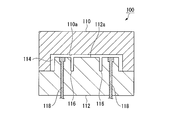
- thermoplastic PP resin composition a resin injection molding method using the mold 100 illustrated in FIG. 1 will be described.
- the mold 100 includes a design surface mold 110 for forming a design surface side of a resin injection molded product (hereinafter, simply referred to as “injection molded product”), and an injection molding.
- the cavity forming surface 112a of the non-design surface mold 112 has a plurality of recessed portions (in FIG. 1, simplified to be expressed as two recessed portions 116 and 116) for forming ribs and the like on the non-design surface side of the injection molded product. Is formed).
- the mold cavity 114 is formed by clamping the design surface mold 110 and the non-design surface mold 112.
- the mold cavity 114 extends vertically from the plate-shaped portion, the side wall portion extending vertically from the non-design surface side at both ends of the plate-shaped portion, and the non-design surface side between the pair of side wall portions in the plate-shaped portion.
- the non-design surface mold 112 is provided with ejector pins 118 and 118 for extruding an injection molded product after injection molding to remove the mold.
- Examples of the resin injection molding method using the mold 100 include a method having the following injection filling step, molding step, and demolding step.
- Injection filling step A step of injecting and filling a molten thermoplastic PP resin composition into a mold cavity 114 formed by clamping a design surface mold 110 and a non-design surface mold 112.
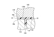
- Molding step a step of forming the injection pressure product 10 as shown in FIG. 2 by forming the resin pressure to reach a negative pressure within 7 seconds after completion of the injection filling of the thermoplastic PP resin composition.
- Demolding step A step of opening the design surface mold 110 and the non-design surface mold 112 and demolding the molded injection molded product 10.
- thermoplastic PP resin composition used in the resin injection molding method according to the first embodiment of the present invention contains a crystalline polypropylene resin (hereinafter referred to as “crystalline PP resin”) and a rubber component.
- crystalline PP resin known ones can be used without limitation, and examples thereof include a homopolymer of propylene and a copolymer of propylene and a small amount of an ⁇ -olefin such as ethylene.
- the rubber component include ethylene propylene rubber (EPR) and ethylene propylene diene rubber (EPDM).
- the rubber component content in the thermoplastic PP resin composition is 1 to 40% by mass, preferably 5 to 35% by mass, and more preferably 10 to 30% by mass. If the content of the rubber component is not less than the lower limit (1% by mass), the volume shrinkage of the thermoplastic PP resin composition is further reduced, and the cavity formation of the thermoplastic PP resin composition and the design surface mold 110 is performed during molding. Since it becomes easy to maintain the state which contact
- the lower limit 1% by mass
- the volume shrinkage of the thermoplastic PP resin composition becomes larger, and the thermoplastic PP resin composition and the cavity forming surface 110a of the design surface mold 110 are in close contact during molding. Since it becomes difficult to maintain the state, the sinking suppression effect is not exhibited.
- the content of the rubber component exceeds the upper limit (40% by mass), it becomes difficult to maintain the physical properties as a polypropylene resin, and thus the practicality as a product becomes poor.
- thermoplastic PP resin composition used in the first embodiment of the present invention may contain components other than the crystalline PP resin and the rubber component as long as the effects of the present invention are not impaired.
- other components include reinforcing materials such as talc and glass fiber, pigments for coloring, and anti-aging agents for preventing deterioration.
- the temperature T 1 of the cavity forming surface 110a of the design surface mold 110 before injection filling of the thermoplastic PP resin composition In the injection filling process, the temperature T 2 of the cavity forming surface 112a of the non-design surface mold 112 60 - and 120 ° C., and keep high 5 ⁇ 50 ° C. than the temperature T 2 of the temperature T 1 of the cavity forming surface 110a of the design surface mold 110 of the non-design surface mold 112 cavity forming surface 112a. Then, the molten thermoplastic PP resin composition is injected and filled into the mold cavity 114 formed by the design surface mold 110 and the non-design surface mold 112 in the state where the temperature is set as described above. By setting the temperature T 1 and the temperature T 2 before injection filling to the above-described conditions, it is possible to suppress the occurrence of sink marks on the design surface of the obtained injection molded product. The factors for obtaining such effects are considered as follows.
- Crystalline PP resin has a large volume shrinkage at the time of molding, and thus is a resin in which sink marks are easily generated.
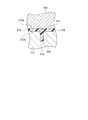
- the conventional method in which the temperature T 1 and the temperature T 2 are set to the same temperature, as shown in FIG.
- the occurrence of sink marks is remarkable on the design surface 210a side of 210 and the non-design surface 210b side.
- the cavity forming surface 112a of the non-design surface mold 112 has a lower temperature than the cavity forming surface 110a of the design surface mold 110.
- thermoplastic PP resin composition injected and filled into the mold cavity 114 is cooled faster on the non-design surface mold 112 side than on the design surface mold 110 side.
- the gap between the non-design surface mold 112 side and the resin molded product is likely to occur due to the volume shrinkage of the thermoplastic PP resin composition.
- the change in the shape of the thermoplastic PP resin composition due to the volume shrinkage occurs so as to shrink from the non-design surface mold 112 side toward the design surface mold 110 side.
- the temperature of the cavity forming surface 110a of the design surface mold 110 is 65 to 120 ° C., the cooling of the resin is slower than in normal molding.
- the state in which the thermoplastic PP resin composition is in close contact with the cavity forming surface 110a of the design surface mold 110 during the molding is maintained for a long time, so that the sink caused by the volume shrinkage is injection-molded as shown in FIG. It is thought that it concentrates on the non-design surface 10b side of the product 10 and the occurrence of sink marks on the design surface 10a side of the injection molded product 10 is suppressed.
- the occurrence of sink marks is not suppressed as a whole, and the resulting sink marks are gathered on the non-design surface side.
- the occurrence of sink marks on the design surface side is suppressed. Since the non-design surface of an injection-molded product is not a surface that is normally touched by consumers, there is no problem as a product even if the amount of sink marks on the non-design surface side increases.
- Temperature T 1 of the cavity forming surface 110a of the design surface mold 110 is preferably 65 ⁇ 120 ° C., more preferably 75 ⁇ 118 ° C., more preferably 80 ⁇ 115 ° C.. If the temperature T 1 is the lower limit (65 ° C.) or higher, easily prevent the sink mark occurs in the design surface 10a of the injection molded article 10. Further, if the temperature T 1 is the upper limit (120 ° C.) or less, crystallization easily proceeds crystalline PP resin injection molded article 10 to be deformed when the demolding without extended cooling time It is easy to suppress. Temperature T 2 of the cavity forming surface 112a of the non-design surface mold 112, at 60 ° C.
- the temperature difference between the cavity forming surface 112a of the cavity forming surface 110a and the non-design surface mold 112 of the design surface mold 110 may be appropriately set within a range of +5 to + 50 ° C. Since the temperature T 1 and the temperature T 2 are 60 ° C. or more, the volume shrinkage of the thermoplastic PP resin composition during molding becomes small, and the thermoplastic PP resin composition becomes the design surface mold 110 during molding. It is possible to hold the state in close contact with the cavity forming surface 110a for a long time, and the occurrence of sink marks on the design surface is suppressed. Moreover, the weld appearance of the obtained injection-molded product is also improved.
- the temperature difference (T 1 ⁇ T 2 ) between the cavity forming surface 110a of the design surface mold 110 and the cavity forming surface 112a of the non-design surface mold 112 is more preferably +5 to + 30 ° C., and further preferably +5 to + 20 ° C. If the temperature difference (T 1 ⁇ T 2 ) is + 5 ° C. or more, the occurrence of sink marks on the design surface 10a of the injection molded product 10 can be suppressed. If the temperature difference (T 1 -T 2 ) is equal to or less than the upper limit (+ 30 ° C.), it is easy to suppress the rapid crystallization of the crystalline PP resin on the non-design surface mold 112 side. Therefore, the thermoplastic PP resin composition tends to shrink from the non-design surface mold 112 side toward the design surface mold 110 side, and sink marks are generated on the design surface by concentrating sink marks on the non-design surface side. It becomes easy to suppress.
- Form for controlling the temperature T 2 of the cavity forming surface 112a of the temperatures T 1 and the non-design surface mold 112 of cavity forming surface 110a of the design surface mold 110 is not particularly limited, non-design the design surface mold 110 Only the vicinity of the cavity forming surfaces 110a and 112a of the surface mold 112 may be heated and controlled, or the design surface mold 110 and the non-design surface mold 112 may be heated and controlled as a whole. Also, the heating method is not particularly limited, and a known heating method can be employed without limitation.
- the temperature of the thermoplastic PP resin composition to be injected and filled is preferably 180 to 240 ° C.
- the injection filling time of the thermoplastic PP resin composition is preferably 0.1 to 10 seconds. The injection filling time is the time from the start to the completion of injection filling.
- the molding step molding is performed by causing the resin pressure in the mold to reach a negative pressure within 7 seconds after completion of injection filling of the thermoplastic PP resin composition. Thereby, since it can become a free surface before the skin layer on the non-design surface side develops, it is possible to sufficiently collect sink marks on the non-design surface side and suppress the occurrence of sink marks on the design surface. .
- the time t from the completion of injection filling to the resin pressure reaching a negative pressure (hereinafter referred to as “negative pressure arrival time t”) is preferably within 5 seconds, and more preferably within 3 seconds. As the negative pressure arrival time t is shorter, it is easier to suppress the occurrence of sink marks on the design surface of the obtained injection molded product.
- the fact that the resin pressure reaches a negative pressure means that the resin pressure becomes zero after completion of injection filling.
- Resin of the thermoplastic PP resin composition is controlled by the clamping force of the design surface mold 110 and the non-design surface mold 112 or the injection pressure of the thermoplastic PP resin composition
- the negative pressure arrival time t can be adjusted to a desired range.
- the clamping force (unit: N) of the design surface mold 110 and the non-design surface mold 112 is used as the product projected area (unit: N).
- the resin pressure reaching a negative pressure it is preferable to assist the resin pressure reaching a negative pressure by reducing the pressure to 1 to 20 MPa by mm 2 ), and to reduce the product projection area to a value by multiplying the pressure by 1 to 10 MPa. It is more preferable to assist the resin pressure reaching a negative pressure. Thereby, it becomes easier to suppress the occurrence of sink marks on the design surface of the injection molded product.
- the pressure required to fill the cavity with the molten resin is high, and the resin pressure immediately after completion of the injection is high.
- the shrinkage amount in the thickness direction is small, it may be difficult to reach the negative pressure within a predetermined time only by controlling the resin filling amount.
- the negative pressure arrival time can be set within a desired time by controlling the resin pressure by the mold clamping force, which is advantageous.
- the resin pressure after reducing the mold clamping force is 20 MPa or more, it may be difficult to reliably reach the negative pressure within a desired time only by reducing the pressure due to subsequent cooling and shrinkage of the resin. It is not preferable.
- the pressure is 1 MPa or less, the resin pressure becomes non-uniform, and the resin pressure may reach a negative pressure locally due to the pressure-lowering operation. In this case, it is difficult to reliably generate a gap between the non-design surface side and the mold, and a gap is likely to be generated between the design surface side and the mold.
- the product projected area is the area when the injection molded product 10 in the mold cavity 114 is projected onto the design surface mold 110 or the non-design surface mold 112, that is, the injection molded product 10 in the mold cavity 114 is designed. It is an area when viewed from the surface mold 110 side or the non-design surface mold 112 side.
- the mold clamping force (unit: N) of the design surface mold 110 and the non-design surface mold 112 before the injection filling of the thermoplastic PP resin composition is completed is the product projected area (unit: mm 2 ) of the mold cavity 114. ) Is multiplied by a pressure of 20 to 40 MPa, but is not limited to this value.
- Temperature T 2 of the cavity forming surface 112a between the temperature T 1 of the cavity forming surface 110a of the design surface mold 110 in a molding process non design surface mold 112 be varied as long as conditions are satisfied in the injection filling process However, from the viewpoint of reducing energy loss, it is preferable to maintain the temperature at the injection filling process.
- the surface area per unit area of the cavity forming surface 110a of the design surface mold 110 is larger than the surface area per unit area of the cavity forming surface 112a of the non-design surface mold 112. It is preferable.
- the contact area between the thermoplastic PP resin composition filled in the mold cavity 114 and the cavity forming surface 110a of the design surface mold 110 is such that the thermoplastic PP resin composition and the non-design surface mold 112 have a cavity. Since it becomes larger than a contact area with the formation surface 112a, this thermoplastic PP resin composition becomes easy to stick to the cavity formation surface 110a of the design surface mold 110.
- sink marks tend to concentrate on the non-design surface side of the injection molded product, and sink marks are less likely to occur on the design surface of the injection molded product.
- An injection-molded product can be obtained. Further, in the first embodiment of the present invention, many sink marks are generated on the non-design surface side. Therefore, as shown in FIG. Therefore, the punching resistance of the rib 14 at the time of demolding by the ejector pin 118 is small, and even the injection molded product 10 having the thin plate-like portion 12 is hardly deformed. Furthermore, in the first embodiment of the present invention, it is not necessary to use a special mold, and it is not necessary to repeatedly heat or cool the mold, so that energy loss can be reduced.
- the resin injection molding method of the present invention is not limited to the method using the mold 100 described above.
- the resin injection-molded article according to the second embodiment of the present invention is an injection-molded article manufactured by the resin injection molding method according to the first embodiment of the present invention described above.
- the resin injection-molded article according to the second embodiment of the present invention has a design surface and a non-design surface, and is manufactured by the resin injection molding method according to the first embodiment of the present invention described above.
- Applications of the injection molded product of the present invention include automobile interior parts such as automobile pillars, home appliances such as a washing machine top plate, and housing equipment such as toilet seat covers.
- Example 1 A commercially available polypropylene resin (rubber content: 1% by mass / analyzed by pyrolysis gas chromatography) is used as a thermoplastic PP resin composition to produce an injection molded product having a rib shape with a thickness of 1.5 mm.
- An injection-molded product was manufactured using a mold for the purpose. The thickness of the rib was set to three types: 2.0 mm, 1.5 mm, and 1.2 mm.
- Mirror surface processing (# 1200) was applied to the cavity forming surface of the design surface mold in the mold to be used.
- the temperature T 1 of the cavity forming surface of the design surface mold before injection filling of the thermoplastic PP resin composition is 115 ° C.
- the temperature T 2 of the cavity forming surface of the non-design surface mold. was 110 ° C.
- the temperature difference (T 1 -T 2 ) was 5 ° C.
- the temperature T 1 and the temperature T 2 were measured with a contact-type surface temperature measuring device immediately before injection filling.
- the barrel temperature when injection-filling the thermoplastic PP resin composition was 200 ° C., and the injection-filling time was 2 seconds.
- the mold clamping force (unit: N) of the design surface mold and the non-design surface mold before injection filling is set to a value obtained by multiplying the product projection area (unit: mm 2 ) of the mold cavity by a pressure of 30 MPa. did.
- the resin pressure is reduced by lowering the mold clamping force (unit: N) of the design surface mold and the non-design surface mold to a value obtained by multiplying the product projection area of the mold cavity by the pressure 2 MPa.
- the negative pressure was reached, and the negative pressure arrival time t was adjusted to 3 seconds.
- the resin pressure was measured by a resin pressure sensor (direct pressure type pressure sensor manufactured by Nippon Kisler Co., Ltd.) attached to the mold, and the time from the completion of injection filling until the resin pressure reached 0 was defined as a negative pressure arrival time t.
- Example 2 to 15 The composition of the thermoplastic PP resin composition, the processing method of the cavity forming surface of the design surface mold, the temperatures T 1 and T 2 of the cavity forming surface of the design surface mold and the non-design surface mold, and the negative pressure arrival time t An injection molded product was obtained in the same manner as in Example 1 except that the changes were made as shown in Table 1.
- thermoplastic PP resin composition The composition of the thermoplastic PP resin composition, the processing method of the cavity forming surface of the design surface mold, the temperatures T 1 and T 2 of the cavity forming surface of the design surface mold and the non-design surface mold, and the negative pressure arrival time t An injection molded product was obtained in the same manner as in Example 1 except that the changes were made as shown in Table 1.
- the injection-molded articles of Examples 1 to 15 molded by the resin injection molding method according to the first embodiment of the present invention are made of crystalline PP resin, but are non-designed compared to Comparative Examples 1 and 3 to 5.
- the generation of sink marks on the design surface of the portion where the ribs were formed on the surface side was suppressed, and the sink marks were also suppressed on the entire design surface.
- Examples 7 to 11 in which the cavity forming surface of the design surface mold is leather-textured are compared with Examples 1 to 4 and 6 in which the cavity forming surface of the design surface mold is mirror-finished or honed. The occurrence of sink marks was further suppressed.
- Comparative Example 1 in which the thermoplastic PP resin composition containing no rubber component is used, all the conspicuous sink marks are present in the portion of the design surface where the ribs having a thickness of 1.2 mm, 1.5 mm, and 2.0 mm are provided. There has occurred.
- Comparative Example 2 in which the temperature difference (T 1 -T 2 ) between the cavity-forming surface of the design surface mold and the non-design surface mold before injection filling is less than + 5 ° C., the portion on the design surface where ribs are provided However, there was a conspicuous sink on the portion of the design surface where no ribs were provided, and the overall design was low.
Landscapes
- Engineering & Computer Science (AREA)
- Manufacturing & Machinery (AREA)
- Mechanical Engineering (AREA)
- Chemical & Material Sciences (AREA)
- Health & Medical Sciences (AREA)
- Chemical Kinetics & Catalysis (AREA)
- Medicinal Chemistry (AREA)
- Polymers & Plastics (AREA)
- Organic Chemistry (AREA)
- Injection Moulding Of Plastics Or The Like (AREA)
- Moulds For Moulding Plastics Or The Like (AREA)
Priority Applications (5)
| Application Number | Priority Date | Filing Date | Title |
|---|---|---|---|
| MX2014015453A MX350649B (es) | 2012-06-22 | 2013-06-20 | Método de moldeo por inyección de resina y producto de resina moldeado por inyección. |
| IN10844DEN2014 IN2014DN10844A (zh) | 2012-06-22 | 2013-06-20 | |
| US14/408,473 US9242400B2 (en) | 2012-06-22 | 2013-06-20 | Resin injection molding method and resin injection molded product |
| CA2877098A CA2877098C (en) | 2012-06-22 | 2013-06-20 | Resin injection molding method and resin injection molded product |
| CN201380032286.5A CN104379315B (zh) | 2012-06-22 | 2013-06-20 | 树脂的注射成型方法及树脂注射成型品 |
Applications Claiming Priority (2)
| Application Number | Priority Date | Filing Date | Title |
|---|---|---|---|
| JP2012-141382 | 2012-06-22 | ||
| JP2012141382A JP5997949B2 (ja) | 2012-06-22 | 2012-06-22 | 樹脂の射出成形方法 |
Publications (1)
| Publication Number | Publication Date |
|---|---|
| WO2013191241A1 true WO2013191241A1 (ja) | 2013-12-27 |
Family
ID=49768834
Family Applications (1)
| Application Number | Title | Priority Date | Filing Date |
|---|---|---|---|
| PCT/JP2013/066946 WO2013191241A1 (ja) | 2012-06-22 | 2013-06-20 | 樹脂の射出成形方法及び樹脂の射出成形品 |
Country Status (7)
| Country | Link |
|---|---|
| US (1) | US9242400B2 (zh) |
| JP (1) | JP5997949B2 (zh) |
| CN (1) | CN104379315B (zh) |
| CA (1) | CA2877098C (zh) |
| IN (1) | IN2014DN10844A (zh) |
| MX (1) | MX350649B (zh) |
| WO (1) | WO2013191241A1 (zh) |
Cited By (1)
| Publication number | Priority date | Publication date | Assignee | Title |
|---|---|---|---|---|
| US11485060B2 (en) | 2017-08-03 | 2022-11-01 | Volkswagen Aktiengesellschaft | Method for producing a trim part of a motor vehicle |
Families Citing this family (3)
| Publication number | Priority date | Publication date | Assignee | Title |
|---|---|---|---|---|
| JP2015223732A (ja) * | 2014-05-27 | 2015-12-14 | クミ化成株式会社 | 射出成形用金型 |
| EP3332936A1 (en) | 2016-12-07 | 2018-06-13 | Letoplast Invest NV | Method for producing an injection moulded product with a higher rib-to-wall thickness ratio |
| JP7255415B2 (ja) * | 2019-08-02 | 2023-04-11 | コニカミノルタ株式会社 | 射出成形用金型および製造方法 |
Citations (5)
| Publication number | Priority date | Publication date | Assignee | Title |
|---|---|---|---|---|
| JPH03281213A (ja) * | 1990-03-29 | 1991-12-11 | Olympus Optical Co Ltd | 光学成形体の射出成形金型および成形方法 |
| JPH08104792A (ja) * | 1994-10-06 | 1996-04-23 | Ube Ind Ltd | 自動車内装部品用ポリプロピレン系樹脂組成物及びそれを用いて成形してなる自動車内装用部品 |
| JP2000043110A (ja) * | 1998-07-30 | 2000-02-15 | Ube Ind Ltd | 射出成形方法 |
| JP2000176944A (ja) * | 1998-12-18 | 2000-06-27 | Ricoh Co Ltd | プラスチック成形品の製造方法及びプラスチック成形用金型 |
| JP2005313330A (ja) * | 2004-04-27 | 2005-11-10 | Honda Motor Co Ltd | 射出成形金型 |
Family Cites Families (13)
| Publication number | Priority date | Publication date | Assignee | Title |
|---|---|---|---|---|
| US6517755B1 (en) * | 1919-07-18 | 2003-02-11 | Ube Industries, Ltd. | Resin multilayer molding method and mulitlayer molding device |
| EP0066951B1 (en) * | 1981-05-15 | 1985-08-28 | Imperial Chemical Industries Plc | Process for moulding reinforced curable compositions |
| JPH06315961A (ja) | 1993-05-10 | 1994-11-15 | Tohoku Munekata Kk | 可視面にヒケを発生させない射出成形プラスチック製品の製造方法及びその装置 |
| JP3946813B2 (ja) | 1997-04-30 | 2007-07-18 | 日本ジーイープラスチックス株式会社 | ヒケを改善する成形方法 |
| JP2000289073A (ja) | 1999-04-12 | 2000-10-17 | Asahi Chem Ind Co Ltd | ガス加圧射出圧縮成形方法 |
| JP4344421B2 (ja) * | 1999-04-26 | 2009-10-14 | 住友化学株式会社 | 熱可塑性樹脂組成物及びその射出成形体 |
| KR20020026948A (ko) * | 1999-07-27 | 2002-04-12 | 다이니폰 도료 가부시키가이샤 | 금형내 피복성형 방법 |
| JP4266609B2 (ja) * | 2002-10-08 | 2009-05-20 | 株式会社プライムポリマー | 成形方法および樹脂成形体 |
| JP4889962B2 (ja) * | 2004-05-14 | 2012-03-07 | 昭和電工株式会社 | 導電性構造体およびその製造方法ならびに燃料電池用セパレータ |
| WO2007129673A1 (ja) | 2006-05-02 | 2007-11-15 | Hiroyuki Iwami | 熱可塑性樹脂成形用金型、キャビティ型及びそのキャビティ型の製造方法 |
| US7846533B2 (en) * | 2008-03-26 | 2010-12-07 | Hendrickson Usa, L.L.C. | Molded thermoplastic articles |
| CN101712789B (zh) * | 2009-12-25 | 2012-03-21 | 北京中拓机械有限责任公司 | 一种纤维增强注塑制品及其注塑成型方法 |
| CN102343661B (zh) * | 2011-06-29 | 2014-01-29 | 安徽丰原淮海制药有限公司 | 一种直排式吹塑输液软袋的制备方法 |
-
2012
- 2012-06-22 JP JP2012141382A patent/JP5997949B2/ja active Active
-
2013
- 2013-06-20 CA CA2877098A patent/CA2877098C/en not_active Expired - Fee Related
- 2013-06-20 US US14/408,473 patent/US9242400B2/en active Active
- 2013-06-20 CN CN201380032286.5A patent/CN104379315B/zh not_active Expired - Fee Related
- 2013-06-20 WO PCT/JP2013/066946 patent/WO2013191241A1/ja active Application Filing
- 2013-06-20 MX MX2014015453A patent/MX350649B/es active IP Right Grant
- 2013-06-20 IN IN10844DEN2014 patent/IN2014DN10844A/en unknown
Patent Citations (5)
| Publication number | Priority date | Publication date | Assignee | Title |
|---|---|---|---|---|
| JPH03281213A (ja) * | 1990-03-29 | 1991-12-11 | Olympus Optical Co Ltd | 光学成形体の射出成形金型および成形方法 |
| JPH08104792A (ja) * | 1994-10-06 | 1996-04-23 | Ube Ind Ltd | 自動車内装部品用ポリプロピレン系樹脂組成物及びそれを用いて成形してなる自動車内装用部品 |
| JP2000043110A (ja) * | 1998-07-30 | 2000-02-15 | Ube Ind Ltd | 射出成形方法 |
| JP2000176944A (ja) * | 1998-12-18 | 2000-06-27 | Ricoh Co Ltd | プラスチック成形品の製造方法及びプラスチック成形用金型 |
| JP2005313330A (ja) * | 2004-04-27 | 2005-11-10 | Honda Motor Co Ltd | 射出成形金型 |
Cited By (1)
| Publication number | Priority date | Publication date | Assignee | Title |
|---|---|---|---|---|
| US11485060B2 (en) | 2017-08-03 | 2022-11-01 | Volkswagen Aktiengesellschaft | Method for producing a trim part of a motor vehicle |
Also Published As
| Publication number | Publication date |
|---|---|
| JP2014004737A (ja) | 2014-01-16 |
| CN104379315A (zh) | 2015-02-25 |
| MX2014015453A (es) | 2015-05-08 |
| US20150190953A1 (en) | 2015-07-09 |
| JP5997949B2 (ja) | 2016-09-28 |
| CA2877098A1 (en) | 2013-12-27 |
| MX350649B (es) | 2017-09-12 |
| CA2877098C (en) | 2020-04-28 |
| US9242400B2 (en) | 2016-01-26 |
| CN104379315B (zh) | 2016-10-26 |
| IN2014DN10844A (zh) | 2015-09-04 |
Similar Documents
| Publication | Publication Date | Title |
|---|---|---|
| JP5162364B2 (ja) | 多層成形品の製造方法および多層成形品 | |
| AU2009249509B2 (en) | Molded thermoplastic articles | |
| KR101793851B1 (ko) | 금속/수지 복합 구조체 | |
| WO2013191241A1 (ja) | 樹脂の射出成形方法及び樹脂の射出成形品 | |
| JP2015223732A (ja) | 射出成形用金型 | |
| JP2014104680A (ja) | 射出成形用金型、樹脂の射出成形方法及び射出成形品 | |
| JP3377010B2 (ja) | 薄肉成形品の製造方法 | |
| JP6851232B2 (ja) | 樹脂射出成形品、この樹脂射出成形品を用いた電動工具用のケーシング | |
| JP3797512B2 (ja) | 射出成形用金型 | |
| CN105690804B (zh) | 包覆模制预浸料制成的插件的方法及其用途 | |
| JP2009196158A (ja) | インサート成形体及びその製造方法 | |
| JP6514994B2 (ja) | インモールド成形体の製造方法 | |
| WO2019235031A1 (ja) | 成形品の製造方法 | |
| JP5810964B2 (ja) | 樹脂成形品の成形方法 | |
| JP2017217850A (ja) | 厚肉成形品の成形方法 | |
| JP6933806B2 (ja) | 樹脂成形体の製造方法 | |
| JP7123233B2 (ja) | 射出金型、これを含む射出成形機及びこれを用いた射出製品の製造方法 | |
| JPS5949916A (ja) | 熱可塑性樹脂のプレス成形方法 | |
| Michaeli et al. | Back Foaming of Soft-Touch Decorative Films | |
| JP5484747B2 (ja) | インサート成形方法 | |
| KR101142900B1 (ko) | 잔류 응력이 최소화된 성형품의 이중 사출금형 | |
| JPH10225951A (ja) | ガス併用射出成形法 | |
| JP2019188604A (ja) | 発泡ウレタン成形用モールド及びこれを用いた発泡ウレタン製品の製造方法 | |
| JP2005161747A (ja) | トイレ装置 | |
| JPH0985784A (ja) | 射出成形金型 |
Legal Events
| Date | Code | Title | Description |
|---|---|---|---|
| 121 | Ep: the epo has been informed by wipo that ep was designated in this application |
Ref document number: 13807248 Country of ref document: EP Kind code of ref document: A1 |
|
| WWE | Wipo information: entry into national phase |
Ref document number: 14408473 Country of ref document: US Ref document number: MX/A/2014/015453 Country of ref document: MX |
|
| ENP | Entry into the national phase |
Ref document number: 2877098 Country of ref document: CA |
|
| NENP | Non-entry into the national phase |
Ref country code: DE |
|
| WWE | Wipo information: entry into national phase |
Ref document number: IDP00201408222 Country of ref document: ID |
|
| 122 | Ep: pct application non-entry in european phase |
Ref document number: 13807248 Country of ref document: EP Kind code of ref document: A1 |