WO2013190945A1 - 金属ケイ素及び多孔質炭素の製造方法 - Google Patents
金属ケイ素及び多孔質炭素の製造方法 Download PDFInfo
- Publication number
- WO2013190945A1 WO2013190945A1 PCT/JP2013/064265 JP2013064265W WO2013190945A1 WO 2013190945 A1 WO2013190945 A1 WO 2013190945A1 JP 2013064265 W JP2013064265 W JP 2013064265W WO 2013190945 A1 WO2013190945 A1 WO 2013190945A1
- Authority
- WO
- WIPO (PCT)
- Prior art keywords
- gas
- silicon
- rice husk
- porous carbon
- producing
- Prior art date
Links
Images


Classifications
-
- C—CHEMISTRY; METALLURGY
- C01—INORGANIC CHEMISTRY
- C01B—NON-METALLIC ELEMENTS; COMPOUNDS THEREOF; METALLOIDS OR COMPOUNDS THEREOF NOT COVERED BY SUBCLASS C01C
- C01B33/00—Silicon; Compounds thereof
- C01B33/02—Silicon
- C01B33/021—Preparation
- C01B33/027—Preparation by decomposition or reduction of gaseous or vaporised silicon compounds other than silica or silica-containing material
- C01B33/033—Preparation by decomposition or reduction of gaseous or vaporised silicon compounds other than silica or silica-containing material by reduction of silicon halides or halosilanes with a metal or a metallic alloy as the only reducing agents
-
- C—CHEMISTRY; METALLURGY
- C01—INORGANIC CHEMISTRY
- C01B—NON-METALLIC ELEMENTS; COMPOUNDS THEREOF; METALLOIDS OR COMPOUNDS THEREOF NOT COVERED BY SUBCLASS C01C
- C01B32/00—Carbon; Compounds thereof
-
- C—CHEMISTRY; METALLURGY
- C01—INORGANIC CHEMISTRY
- C01B—NON-METALLIC ELEMENTS; COMPOUNDS THEREOF; METALLOIDS OR COMPOUNDS THEREOF NOT COVERED BY SUBCLASS C01C
- C01B32/00—Carbon; Compounds thereof
- C01B32/05—Preparation or purification of carbon not covered by groups C01B32/15, C01B32/20, C01B32/25, C01B32/30
-
- C—CHEMISTRY; METALLURGY
- C01—INORGANIC CHEMISTRY
- C01B—NON-METALLIC ELEMENTS; COMPOUNDS THEREOF; METALLOIDS OR COMPOUNDS THEREOF NOT COVERED BY SUBCLASS C01C
- C01B33/00—Silicon; Compounds thereof
- C01B33/02—Silicon
- C01B33/021—Preparation
Definitions
- the present invention relates to a method for producing metal silicon and porous carbon.
- Patent Document 1 describes a method for continuously producing silicon carbide and silicon nitride from rice husk carbide.
- rice husk carbide is heated while moving in the heating zone in the presence of an inert gas that does not react with carbon.
- Patent Document 2 describes a method for producing a molded body of porous silicon carbide having a structure in which whisker properties and fine particle silicon carbide are combined using carbide of rice husk.
- this method after the surface of the ground rice husk carbide is processed, the surface-treated carbide is formed. And a molded object is heat-processed and a carbonization component is removed.
- Patent Document 3 describes a method for producing metallic silicon using a silicate plant such as rice husk as a raw material.
- silica ash obtained by firing a silicate plant and a metal such as aluminum are heated and reacted in an inert gas atmosphere.
- Patent Document 4 describes a method for producing a silica raw material from rice husk.
- rice husk powder is treated with pressurized hot water to adjust the ratio of silica component and organic component in the rice husk powder.
- Patent Document 5 describes a method for producing high-purity amorphous silica using rice husk.
- alkali components are separated from rice husk by treating rice husk with an acetic acid-containing solution. After washing and drying the rice husk from which the alkali component has been separated, the dried rice husk is carbonized to form rice husk charcoal. This rice husk charcoal is fired to produce high purity silica.
- Patent Document 6 focuses on the carbon component of rice husk, and a method for producing activated carbon is also being studied.
- a step of carbonizing the carbon material a step of subjecting the carbon material treated by the carbonization step to alkali activation, a step of accommodating porous carbon produced by the alkali activation step in a container, and the interior of the container
- a step of introducing hydrogen into the container so that the equilibrium pressure is 0.5 to 6 MPa while maintaining the temperature within a range of 77 to 150 K. It is.
- the problem is that the silica component is melted with an alkali salt and discarded.
- Patent Documents 1 and 2 describe a method for producing silicon carbide
- Patent Document 3 describes a method for producing metal silicon
- Patent Document 4 describes a method for producing a silica raw material
- Patent Document 5 describes a method for producing amorphous silica.
- the rice husk contains silicon and carbon.
- silicon is used as a raw material for silicon carbide, metal silicon, and silica raw materials by the production methods described therein. Both are not effectively utilized. Therefore, the methods described in Patent Documents 1 to 5 include a step for removing carbon that has not been utilized. In these removal steps, a treatment liquid such as an acidic solution or an alkaline solution for removal treatment, and energy for heat treatment are required.
- This invention is made
- the first step of producing rice husk charcoal containing silicon oxide and carbon by the heat treatment of rice husk, the heated first inert gas or reducing gas A second step of producing silicon carbide by exposing the rice husk charcoal to at least one, and a third step of exposing the silicon carbide to a heated atmosphere containing chlorine gas to produce silicon tetrachloride and porous carbon.
- the chlorine gas of the fifth step is used for the third step
- the metal zinc of the fifth step is used for the fourth step.
- rice husk charcoal containing silicon oxide and carbon is generated from rice husk, and silicon carbide is generated from the rice husk charcoal.
- silicon carbide and chlorine gas are reacted to produce porous carbon and silicon tetrachloride.
- silicon tetrachloride and zinc are reacted to form metal silicon and zinc chloride.
- chlorine gas and metal zinc are generated by electrolysis of the zinc chloride, and one of these chlorine gases is used for generating the porous carbon and the other metal zinc is used for generating metal silicon. Therefore, according to this manufacturing method, porous carbon and metallic silicon can be manufactured from rice husks.
- the number of moles of carbon is more than three times the number of moles of SiO 2.
- SiO 2 remains in the subsequent reaction and becomes an impurity in the porous carbon. Therefore, if the ratio of the number of moles of carbon and SiO 2 is 3 times or more, SiC having a large amount of carbon component can be formed, and the impurity component in the porous carbon as the final product can be reduced.
- the rice husk charcoal is treated with an acidic solution before the second step. According to this treatment, impurities contained in the rice husk charcoal are removed by the treatment with the acidic solution, so that the purity of silicon oxide and carbon contained in the rice husk charcoal is increased. Accordingly, since the amount of chlorine gas that reacts with impurities in the third step is reduced, the amount of chlorine gas required in the third step can be reduced.
- the first inert gas contains at least one of Ar and He
- the rice husk charcoal obtained in the first step is 1200 ° C. or higher and 2000 ° C. or lower. Heated to a temperature of In the temperature range of 1200 ° C. or more and 2000 ° C. or less, the reaction between silicon oxide and carbon is promoted, so that silicon carbide can be generated efficiently.
- the reducing gas contains at least one of H 2 and CO
- the rice husk charcoal obtained in the first step is 1200 ° C. or higher and 2000 ° C. or lower. Heated to temperature. In the temperature range of 1200 ° C. or more and 2000 ° C. or less, the reaction between silicon oxide and carbon is promoted, so that silicon carbide can be generated efficiently. Further, since H 2 gas and CO gas promote the reaction between silicon oxide and carbon, silicon carbide can be generated more efficiently.
- the silicon carbide is generated at a pressure of less than 1 atm.
- the said heating atmosphere contains the mixed gas of the said chlorine gas and 2nd inert gas, or the said chlorine gas.
- the atmosphere containing the said chlorine gas is heated to the temperature of 1000 to 1600 degreeC. Since the heating atmosphere is at a temperature of 1000 ° C. or higher, the reaction between chlorine gas and silicon carbide can be promoted. In addition, since the heating atmosphere is a temperature of 1600 ° C. or lower, it is possible to suppress the generated porous carbon structure from graphitizing and to suppress the reduction of the surface area of the porous carbon.
- the fourth step of the production method according to the present invention includes the step of heating the silicon tetrachloride to a temperature of 600 ° C. to 1100 ° C. to generate the silicon tetrachloride gas, and the silicon tetrachloride. Reacting with the vapor of the metal zinc to produce the metal silicon and the zinc chloride, and cooling the zinc chloride to liquefy the zinc chloride. The reaction between silicon tetrachloride and metallic zinc can be promoted.
- the silicon tetrachloride is separated from the porous carbon by discharging the silicon tetrachloride gas from the heated atmosphere. Porous carbon and silicon tetrachloride can be easily separated.
- the zinc chloride gas is discharged from the metal silicon by discharging the silicon tetrachloride gas from the atmosphere containing the vapor of the metal zinc. Separate the zinc chloride. Metallic silicon and zinc chloride can be easily separated.
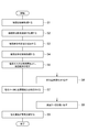
- FIG. 1 is a figure showing the main processes of the manufacturing method of metallic silicon and porous carbon concerning one embodiment.
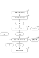
- Drawing 2 is a figure showing the main processes of the manufacturing method of metallic silicon and porous carbon concerning one embodiment.
- FIG. 3 is a diagram schematically illustrating a configuration of a rice husk processing apparatus used in the manufacturing method according to the embodiment.
- Part (a) of FIG. 4 is a diagram showing an example of rice husk, and part (b) of FIG. 4 is a diagram showing an example of rice husk charcoal.
- FIG. 5 is a diagram schematically illustrating a configuration of a processing apparatus for rice husk charcoal used in the manufacturing method according to an embodiment.
- FIG. 6 is a diagram schematically showing a configuration of a rice husk charcoal processing apparatus used in the manufacturing method of one embodiment.
- FIG. 7 is a diagram schematically showing a configuration of a rice husk charcoal processing apparatus used in the manufacturing method of one embodiment.
- FIG. 8 is a diagram schematically showing the configuration of a rice husk charcoal processing apparatus used in the manufacturing method of one embodiment.
- FIG. 9 is a diagram showing a simplified configuration of the zinc reduction device.
- FIG. 10 is a diagram showing a specific configuration of the zinc reduction device.
- FIG. 11A shows an X-ray diffraction (XRD) waveform of the product.
- FIG. 11B shows an X-ray diffraction (XRD) waveform of the product.
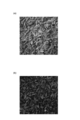
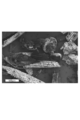
- FIG. 12 shows a photomicrograph of the product.
- FIG. 13 is a diagram showing an X-ray diffraction waveform of a porous carbon material.
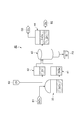
- FIG.1 and FIG.2 is a figure which shows the main processes of the manufacturing method of the metal silicon and porous carbon which concern on one Embodiment.
- the manufacturing method of the present embodiment includes a step S1 for heat treating rice husk, a step S2 for treating rice husk charcoal with an acidic solution, a step S3 for pulverizing and shaping rice husk charcoal, and a rice husk charcoal body.
- Step S4 for heat treating Step S5 for exposing rice husk charcoal in a heating atmosphere containing chlorine gas (Cl 2 gas), Step S6 for removing porous carbon (C), Silicon tetrachloride (SiCl 4 ), a step S7 reacting a metal zinc (Zn), and step S8 taking out the metal silicon (Si), and zinc chloride (ZnCl 2) and an electrolysis of step S9. Then, by repeatedly performing these steps S1 to S9, porous carbon and metallic silicon are continuously produced.
- step S1 (first step) of heat treating rice husk
- silicon (Si) contained in the rice husk is oxidized to produce rice husk charcoal containing silicon oxide (SiO 2 ) and carbon (C) as main components.
- Rice husk charcoal contains about 50% by weight SiO 2 and about 40% by weight C.
- Rice husk charcoal contains, for example, a mixture of hydrogen, nitrogen, potassium, calcium, sodium, manganese, iron, zinc and the like in addition to SiO 2 and C. Many of the mixtures are alkali metals such as potassium, calcium and sodium.
- FIG. 3 is a diagram schematically showing the configuration of the rice husk processing apparatus 10 used in steps S1 to S3.
- the rice husk processing apparatus 10 includes a storage unit 11 that stores rice husk M1 (see part (a) of FIG. 4), a carbonization furnace 12, a gas supply unit 13 that supplies a processing gas G1 to the carbonization furnace 12, and a carbonization furnace 12
- the water supply unit 14 for supplying the cooling water W1, the solution processing unit 15 for processing rice husk charcoal M2 (see part (b) of FIG. 4), and the solution-treated rice husk charcoal M2 are processed into pellets.
- a molding part 16 is provided.
- the carbonization furnace 12 includes a heat treatment unit 12a that accommodates the rice husk M1 and a heater 12b for heating the rice husk M1 in the heat treatment unit 12a. Further, the carbonization furnace 12 includes a cooling unit 12c that stops combustion of the rice husk M1 processed by the heat processing unit 12a. Cooling water W1 is supplied from the water supply unit 14 to the cooling unit 12c, and the rice husk M1 is cooled to a predetermined temperature in the cooling unit 12c.
- the gas supply unit 13 supplies the processing gas G ⁇ b> 1 to the heat processing unit 12 a of the carbonization furnace 12.
- the processing gas G1 is a gas having low reactivity with Si and C contained in the rice husk M1.
- step S ⁇ b> 1 first, the rice husk M ⁇ b> 1 is supplied from the storage unit 11 to the carbonization furnace 12, and the rice husk M ⁇ b> 1 is accommodated in the heat treatment unit 12 a of the carbonization furnace 12.
- the rice husk M1 is heated using the heater 12b while supplying the processing gas G1 from the gas supply unit 13 to the heat processing unit 12a.
- the processing gas G1 is an inert gas such as N 2 and an air gas in an amount insufficient for complete combustion of the rice husk M1, and the rice husk M1 is exposed to a heating atmosphere of 500 ° C. to 1000 ° C.
- the rice husk M1 is heated in an atmosphere that lacks oxygen necessary for the rice husk M1 to burn completely, and thus performs incomplete combustion which is so-called steaming.
- the heated rice husk M1 is moved to the cooling unit 12c and cooled to a predetermined temperature. Then, the rice husk M1 cooled after the heat treatment becomes rice husk charcoal M2, and is moved to the solution processing unit 15.
- the ratio between SiO 2 and carbon in the rice husk charcoal is an important parameter from the stoichiometric relationship in the subsequent reaction.
- the ratio of the number of moles of carbon and SiO 2 is less than 3 times, SiO 2 remains in the subsequent reaction and becomes an impurity in the porous carbon. Therefore, the ratio of the number of moles of carbon and SiO 2 needs to be 3 times or more which is the reaction stoichiometric ratio of SiO 2 + 3C ⁇ SiC + 2CO.
- the number is too large, the pore distribution of the porous carbon cannot take a predetermined distribution.
- Step S2 of treating rice husk charcoal M2 with an acidic solution is performed.
- rice husk charcoal M2 produced in carbonization furnace 12 is processed by solution processing unit 15 to remove impurities such as alkali components and phosphorus contained in rice husk charcoal M2.
- rice husk charcoal M2 is treated using an acidic solution such as hydrochloric acid (HCl).
- silicon carbide is required as an abrasive or a heat-resistant material, it is required to have a uniform particle diameter and a dense particle.
- a manufacturing method capable of imparting functions such as porosity to silicon carbide has been established, but sufficient characteristics have not been obtained for use as industrial silicon carbide. Therefore, a high-pressure process performed to form a dense body and a process such as addition of an additive are required.
- step S3 of pulverizing and forming rice husk charcoal M2 is performed.
- the rice husk charcoal M2 processed by the solution processing unit 15 is formed into a rice husk charcoal body M3 having a predetermined shape in the molding unit 16.
- the rice husk charcoal M2 in a state where the shape of the rice husk M1 is maintained is pulverized.
- the average particle diameter of the crushed rice husk charcoal M2 is 0.1 ⁇ m to 10 ⁇ m. Since the particle diameter of the particles constituting the rice husk charcoal M2 is controlled to a constant value by this pulverization, the subsequent process can be stabilized.
- the crushed rice husk charcoal M2 is formed into a rice husk charcoal body M3 in a pellet form, for example.
- This molding facilitates the conveyance of the rice husk charcoal body M3.
- the rice husk charcoal body M3 will be described.
- step S4 (second step) of heat-treating rice husk carbon body M3, SiO 2 and C contained in rice husk carbon body M3 are reacted with each other to generate silicon carbide (SiC).
- the reaction of the chemical formula (1) can be further promoted by using the processing gas G2 as a reducing gas when the heating atmosphere is 1700 ° C. or lower.
- the reaction of the above chemical formula (1) is difficult to proceed because the standard free energy of formation is positive at 1700 ° C. or lower, but the processing gas G2 contains H 2 , CO, etc., and is a reducing gas. Thus, the reaction for generating SiC is promoted.
- the processing gas G2 may not be a reducing gas.
- FIG. 11A uses rice husk charcoal having a molar ratio of the raw material SiO 2 mole to the carbon mole number of 1: 3.1 (that is, the carbon mole number is 3.1 times the SiO 2 mole number).
- FIG. 2 shows an X-ray diffraction (XRD) waveform of a product treated under atmospheric pressure at 1550 ° C. using He as the atmospheric gas.
- the horizontal axis represents the diffraction angle
- the vertical axis represents the diffraction intensity (unit: CPS (count number)).
- the main product is ⁇ -type silicon carbide, and a small amount of graphite is formed.
- FIG. 11B shows a case where the same raw material as in FIG. 11A is used and the atmosphere gas is N 2 , but generation of Si 3 N 4 is observed in addition to the formation of SiC.
- FIG. 12 shows a micrograph of the product shown in the XRD waveform of FIG. 11A. It can be seen that the rice husk structure remains.
- the reaction is further promoted by reducing the pressure in the reaction furnace 21. Furthermore, by reducing the pressure in the reaction furnace 21, impurities such as alkali and phosphorus such as metal alkali (Na, K) and phosphorus compounds (P 2 O 5 , P 4 ) having a low vapor pressure are removed.
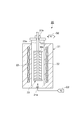
- FIG.5 and FIG.6 is a figure which shows schematically the structure of the processing apparatus 20 of the chaff coal body M3 used in process S4.
- the processing apparatus 20 includes a reaction furnace 21 extending in the vertical direction, a heater 22 embedded in the side wall of the reaction furnace 21, and a mounting shelf 23 disposed in the reaction furnace 21.
- a plurality of rice husk charcoal bodies M3 are mounted on individual stages.
- the mounting shelf 23 is supported by being suspended from above by a support bar 23a.
- An intake port 21a is provided in the lower part of the reaction furnace 21, and a processing gas G2 that is a first inert gas or a reducing gas is introduced from the intake port 21a.
- a processing gas G2 that is a first inert gas or a reducing gas is introduced from the intake port 21a.
- a gas containing at least one of H 2 , N 2 , Ar, He, and CO can be used as the processing gas G2.
- H 2 gas can be used as the processing gas G2.
- the reaction represented by the chemical formula (1) can be promoted by silicon monoxide (SiO) generated by the reaction between SiO 2 and H 2 .
- the processing gas G ⁇ b> 2 moves upward in the reaction furnace 21 and is then discharged from an exhaust port 21 b provided in the upper part of the reaction furnace 21.
- the heater 22 is disposed so as to surround the mounting shelf 23, and heats the rice husk charcoal body M ⁇ b> 3 mounted on the mounting shelf 23.
- step S4 first, the rice husk charcoal body M3 is placed on the placing shelf 23.
- the processing gas G2 is heated using the heater 22 while supplying the processing gas G2 into the reaction furnace 21 from the intake port 21a.
- the processing gas G2 is H 2 gas
- the rice husk charcoal body M3 is exposed to a heated atmosphere of 1200 ° C. or higher and 2000 ° C. or lower for 2 to 10 hours.
- the inside of the reaction furnace 21 is set to a pressure of, for example, less than 1 atmosphere.
- Rice hull charcoal M4 contains SiC. Carbon monoxide (CO) generated simultaneously with the SiC is discharged together with the processing gas G2 from an exhaust port 21b provided in the upper part of the reaction furnace 21.
- the rice husk charcoal body M4 is taken out from the mounting shelf 23.
- step S5 (third step) of exposing rice husk charcoal body M4 in a heated atmosphere containing chlorine gas (Cl 2 ) is performed.
- porous carbon P1 is generated from rice husk coal M4 by performing heat treatment by bringing SiC, which is a compound of Si and C, and Cl 2 gas into contact with each other.
- step S5 SiC Si and Cl 2 gas react to generate SiCl 4, and Si escapes from SiC.
- Si escapes from the rice husk coal body M4 to form porous carbon P1 having a porous carbon structure.
- step S5 SiCl 4 is obtained together with the porous carbon P1. This SiCl 4 is recovered by being cooled to near room temperature in a cooler, for example.
- FIG.7 and FIG.8 is a figure which shows schematically the structure of the processing apparatus 30 of the chaff coal body M4 used in process S5.
- the processing device 30 for the rice husk charcoal body M4 can use, for example, a dehydration sintering furnace used for dehydration processing of a porous preform of an optical fiber.
- the processing apparatus 30 includes a reaction furnace 31, a cooling trap 32, and a storage tank 33.
- the reaction furnace 31 includes a mounting shelf 31a. On the mounting shelf 31a, a plurality of rice husk charcoal bodies M4 are mounted on individual stages. The mounting shelf 31a is supported by being suspended from above by a support bar 31b. A gas inlet 31c is provided in a portion of the reaction furnace 31 below the mounting shelf 31a.
- the processing gas G3 is supplied to the reaction furnace 31 from the gas inlet 31c.
- the processing gas G3 of the present embodiment is a mixed gas of Cl 2 gas and the second inert gas, or substantially 100% Cl 2 gas. In the present embodiment, nitrogen (N 2 ), argon (Ar), helium (He), or the like can be used as the second inert gas.
- a heater 31d is provided outside the reaction furnace 31 so as to surround the mounting shelf 31a.
- the heater 31d heats the atmosphere containing the Cl 2 gas around the rice husk coal body M4 to a temperature of 1000 ° C. or higher and 1600 ° C. or lower, for example.
- a gas discharge port 31 e is provided in the upper part of the reaction furnace 31.
- the gas discharge port 31 e is connected to the cooling trap 32.
- the exhaust gas from the reaction furnace 31 is cooled to, for example, minus 10 ° C. or less by the refrigerant 32 a circulating in the cooling trap 32. Since the boiling point of Cl 2 gas is minus 34 ° C., it is easily separated from SiCl 4 .
- step S5 the rice husk charcoal body M4 is first mounted on the mounting shelf 31a.
- the processing gas G3 is heated using the heater 31d while supplying the processing gas G3 into the reaction furnace 31 from the gas inlet 31c.
- the processing gas G3 is Cl 2 gas
- the rice husk charcoal body M4 is exposed to a heating atmosphere at a temperature of 1000 ° C. to 1600 ° C. or 1100 ° C. to 1300 ° C. for 60 to 600 minutes.
- the reaction of the chemical formula (2) shown in FIG. 8 occurs, Si is released from SiC, and porous carbon P1 is generated in the mounting shelf 31a.
- the porous carbon P1 is taken out from the mounting shelf 31a (step S6).
- SiCl 4 and the processing gas G3 generated by the reaction of the chemical formula (2) are discharged from the gas discharge port 31e to the cooling trap 32 outside the reaction furnace 31.
- the SiCl 4 liquefied by the cooling trap 32 is stored in the storage tank 33 and then sent to the reduction device 40 (see FIGS. 9 and 10) (reference numeral B1 in FIG. 8).
- the processing gas G3 that has passed through the cooling trap 32 is exhausted to the outside of the processing device 30 for the rice husk coal body M4 via the three-way valve 34 or is sent to the gas inlet 31c of the reaction furnace 31 again.
- the reaction of chemical formula (2) proceeds well at a temperature of 1000 ° C. or higher, the specific surface area of the obtained porous carbon P1 has temperature dependence, and the porous carbon P1 having a large specific surface area can be effectively used as activated carbon. It is.
- the specific surface area was maximized by treatment at 1150 ° C. to 1250 ° C., and the value was 1500 m 2 / g to 1700 m 2 / g.
- the activated carbon structure changed from amorphous to graphite, and the surface area decreased to 800 to 1000 m 2 / g.
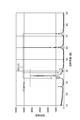
- FIG. 13 shows an X-ray diffraction waveform of a porous carbon material obtained by treatment at 1100 ° C. in a Cl 2 gas atmosphere.
- the horizontal axis represents the diffraction angle, and the vertical axis represents the diffraction intensity (unit: CPS (count number)).
- the main product is confirmed to have a small-angle scattering of less than 15 °, a broad diffraction around 20 °, and a diffraction around 43 ° due to the graphite 01 plane, which are characteristic when SiC is treated. Moreover, it can be confirmed from the diffraction line of 26 ° that a small amount of graphite is formed.
- step S7 (fourth step) in which SiCl 4 and Zn are reacted, high-purity metallic silicon P2 (Si) is extracted from SiCl 4 using a so-called zinc reduction method. More specifically, by reacting Cl 2 and Zn contained in SiCl 4 produced in step S5 with each other, SiCl 4 is reduced to produce metallic silicon P2 (Si).
- Zn is a material selected in combination with SiCl 4 because it does not form a solid solution with Si, the melting point of zinc chloride is relatively low, and the vapor pressure of zinc chloride is high.
- step S7 SiCl 4 and Zn are reacted in the gas phase.
- the boiling point of Zn is 907 ° C., which is relatively low among metals, and has a vapor pressure that can be vaporized even in the vicinity of 800 ° C. Since the boiling point of ZnCl 2 produced by the above gas phase reaction is 756 ° C., the reaction with SiCl 4 can be performed at a temperature of 800 ° C. or higher at which ZnCl 2 does not precipitate.
- step S9 ZnCl 2 is electrolyzed.
- Zn and Cl 2 gas are generated from ZnCl 2 .
- step S9 for example, ZnCl 2 gas is generated from ZnCl 2 by electrolysis of ZnCl 2 in a high-temperature molten state.
- the Cl 2 gas generated in this step S9 is used again in the above-described step S5 (see FIG. 2).
- generated by this process S9 is used again in process S7 mentioned above (refer FIG. 2).
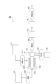
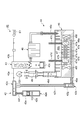
- FIG. 9 and 10 are diagrams schematically showing a configuration of the reduction device 40 used in steps S7, S8, and S9.
- FIG. 9 is a diagram illustrating a simplified configuration of the reduction device 40
- FIG. 10 is a diagram illustrating a specific configuration of the reduction device 40.
- the reduction device 40 includes a vaporizer 41 and a vaporizer 42, a reaction furnace 43, and an electrolysis tank 44.
- the SiCl 4 (reference symbol B1) stored in the storage tank 33 of the processing device 30 for the rice husk coal body M4 described above is sent to the vaporizer 41 and vaporized.
- the vaporizer 42 Zn is vaporized.
- the vaporized SiCl 4 and Zn are sent to the reaction furnace 43.
- SiCl 4 and Zn are reacted at a high temperature in the reaction furnace 43.
- the reaction occurs in the above-mentioned chemical formula by the reaction (3), metal silicon P2 and ZnCl 2 are generated.
- ZnCl 2 is trapped at a temperature not lower than the melting point (280 ° C.) and lower than the boiling point, and is sent to the electrolysis tank 44.
- ZnCl 2 undergoes a reaction of chemical formula (4) by electrolysis with a direct current, and ZnCl 2 is separated into Zn and Cl 2 gas.
- the generated Cl 2 gas is sent as the processing gas G3 to the processing device 30 of the rice husk coal body M4 (G3 in FIGS. 8 and 9), and Zn is sent to the vaporizer 42 (reference numeral B2 in FIG. 9).
- the carburetor 42 includes an in-system carburetor 42a, a continuous operation carburetor 42b, and a collecting pipe 42c.
- the in-system charging carburetor 42 a has a gate valve 42 d, and Zn can be input from the outside of the reducing device 40.
- Zn is accommodated in the vaporizing chamber 42e of the in-system charging vaporizer 42a and vaporizes.
- the vaporizing chamber 42e and the collecting pipe 42c are connected to each other by a pipe 42f.
- the continuous operation vaporizer 42b has a zinc evaporation part 42g that accommodates and vaporizes Zn taken out from the electrolysis tank 44.
- the zinc evaporation part 42g and the collecting pipe 42c are connected to each other by a pipe 42h.
- the piping 42h of the in-system charging carburetor 42a and the continuous operation carburetor 42b is made of ceramics (alumina or the like), for example.
- the zinc evaporation part 42g and the collecting pipe 42c of the vaporizer 42b for continuous operation are comprised, for example with carbon.
- the in-system carburetor 42a, the continuous operation carburetor 42b, and the collecting pipe 42c are heated to a temperature of 800 ° C. or higher, for example, 900 ° C. to 1000 ° C., in order to efficiently generate metallic zinc vapor. .
- the reaction furnace 43 is, for example, a quartz container.
- the upper part of the reaction furnace 43 is connected to the collecting pipe 42c of the vaporizer 42 through a quartz pipe 43a, and the vaporized Zn is sent to the reaction furnace 43 through the pipe 43a.
- SiCl 4 (reference numeral B1) flows into the upper portion of the reaction furnace 43 through a quartz pipe 43b.
- the reaction furnace 43 is heated to a high temperature of 1200 ° C. to 1400 ° C., and Zn and SiCl 4 react with each other in the reaction furnace 43.
- the resulting metal silicon P2 is accommodated in an unheated container 43c provided inside the reaction furnace 43.
- ZnCl 2 passes through a fine particle trap 45 for removing fine particles of metal silicon P 2, and is then sent to the electrolysis tank 44.
- the fine particle trap 45 is made of, for example, quartz and is heated to a high temperature of 900 ° C. to 1000 ° C.
- the purity of the obtained metal silicon P2 is a very high value such as 99.9995%, and this purity can be used as a material for solar cells.
- Zn and O 2 were confirmed as impurities in the metal silicon P2.
- the electrolysis tank 44 includes a main body 46 and an electrode structure 47.
- the main body 46 has an electrolytic bath 46a for accommodating and electrolyzing molten ZnCl 2 and a heater 46f as a heat source for heating the inside of the electrolytic bath 46a.
- a space 46b is provided above the electrolytic cell 46a, a pipe 46c connected to the particulate trap 45 is disposed at one end in the horizontal direction of the space 46b, and a pipe 46d (demister) is disposed at the other end. ZnCl 2 introduced from the pipe 46c is guided to the electrolytic cell 46a.
- the Cl 2 gas generated in the electrolytic bath 46a is discharged from the pipe 46d through the space 46b, and is supplied as the processing gas G3 to the processing device 30 of the rice husk coal body M4.
- a filter 48 made of Teflon (registered trademark) resin is provided at the tip of the pipe 46d.
- a pipe 46e is connected to the bottom of the electrolytic cell 46a, and high-purity Zn deposited on the bottom of the electrolytic cell 46a is sent to the continuous operation vaporizer 42b through the pipe 46e.
- the electrode structure 47 has a plurality of electrode plates 47a.
- the plurality of electrode plates 47a are juxtaposed in the plate thickness direction with a gap, and are arranged in the electrolytic cell 46a with the plate thickness direction as a horizontal direction.
- the plurality of electrode plates 47a are made of a conductive material that is resistant to chlorine and resistant to chlorine, such as a high-purity carbon material, and are penetrated by one or a plurality of rod-shaped members 47b extending in the horizontal direction, so that the mutual positions Relationship is maintained.
- a predetermined positive voltage is applied to the electrode plate 47a located at one end in the horizontal direction among the plurality of electrode plates 47a via an energization member 47c electrically connected to the electrode plate 47a. Functions as an anode.
- a predetermined negative voltage is applied to the electrode plate 47a located at the other end in the horizontal direction via an energization member 47d electrically connected to the electrode plate 47a, and this electrode plate 47a functions as a cathode.
- the electrode plate 47a disposed between the anode and the cathode is given a potential gradient between the positive voltage and the negative voltage via the energizing member, and each of these electrode plates 47a functions as an intermediate electrode. .
- ZnCl 2 introduced from the pipe 46c is taken into the electrolytic cell 46a. Since the inside of the electrolytic cell 46a is maintained at a temperature higher than the melting point of Zn, for example, 500 ° C. to 700 ° C. by the heater, ZnCl 2 is maintained in a molten state.
- the inside of the electrolytic cell 46a are arranged a plurality of electrode plates 47a, a plurality of electrode plates 47a are immersed in ZnCl 2 were melted.
- a current flows in ZnCl 2 through the surface (electrolytic surface) facing between adjacent electrode plates 47a, electric ZnCl 2 within Cl 2 and Zn Disassembled.
- the Zn thus produced has a specific gravity greater than that of the ZnCl 2 melt, and therefore accumulates at the bottom of the electrolytic cell 46a and is sent to the continuous operation vaporizer 42b through the pipe 46e.
- the generated Cl 2 becomes Cl 2 gas, moves upward of the electrolytic cell 46a, and is sent to the processing device 30 for the rice husk charcoal body M4 through the pipe 46d.
- rice husk charcoal M2 containing SiO 2 and C is generated from rice husk M1, and SiC is generated from the rice husk charcoal M2.
- SiC and Cl 2 gas are reacted to generate porous carbon P1 and SiCl 4 .
- SiCl 4 and Zn are reacted to generate metallic silicon P 2 and ZnCl 2 .
- the Cl 2 gas generated by the electrolysis is used for generating the porous carbon P1, and the Zn generated by the electrolysis is used for generating the metal silicon P2. Therefore, according to this manufacturing method, porous carbon P1 and metal silicon P2 can be manufactured from rice husk M1.
- rice husk charcoal M2 is treated with an acidic solution before the second step S4.
- impurities contained in the rice husk charcoal M2 are removed by the treatment with the acidic solution, so that the purity of SiO 2 and C contained in the rice husk charcoal M2 is increased. Therefore, since the amount of Cl 2 gas that reacts with impurities in the third step S5 is reduced, the amount of Cl 2 gas required in the third step S5 can be reduced.
- the process gas comprises H 2, the process gas is heated to temperatures below 2000 ° C. 1200 ° C. or higher. In the temperature range of 1200 ° C. or more and 2000 ° C. or less, the reaction between SiO 2 and C is promoted, so that SiC can be generated efficiently. Further, H 2 gas, so to promote the reaction between the SiO 2 and C, and can be produced more efficiently SiC.
- SiC is generated at a pressure of less than 1 atmosphere.
- the heating atmosphere contains a mixed gas of Cl 2 gas and the second inert gas or substantially 100% Cl 2 gas. According to such a heating atmosphere, an appropriate reaction can be promoted.
- an atmosphere containing Cl 2 gas is heated to a temperature of 1000 ° C. or higher and 1600 ° C. or lower. Since the heating atmosphere is at a temperature of 1000 ° C. or higher, the reaction between Cl 2 gas and SiC can be promoted. Moreover, since the heating atmosphere is a temperature of 1600 ° C. or lower, it is possible to suppress the structure of the generated porous carbon P1 from being graphitized, and to suppress a decrease in the specific surface area of the porous carbon P1.
- the fourth step S7 heats the SiCl 4 at a temperature of 600 ° C. or higher 1100 ° C. or less, a step of generating a gas SiCl 4, and the gas SiCl 4 is reacted with the vapor of Zn, metallic silicon and a step of generating the P2 and ZnCl 2, a step of liquefying the ZnCl 2 was cooled ZnCl 2, a.
- the reaction between SiCl 4 and Zn can be promoted.
- SiCl 4 is separated from the porous carbon P1 by discharging the SiCl 4 gas from the heated atmosphere.
- the porous carbon P1 and SiCl 4 can be easily separated.
- ZnCl 2 is separated from the metal silicon P1 by discharging a gas of ZnCl 2 from the heating atmosphere.
- the metallic silicon P1 and ZnCl 2 can be easily separated.
- the rice husk charcoal body M4 containing SiC can be produced without using a complicated apparatus for treating a large amount of organic decomposition product gas such as methane and carbon monoxide generated during the treatment of the rice husk M1.
- the apparatus configuration can be simplified by combining the first step S1 for generating rice husk charcoal M2 containing SiO 2 and the second step S4 for generating SiC from SiO 2 .
- siliceous plant-derived materials other than rice husks include rice straw and diatoms.
- the present invention is applicable to a method for producing metal silicon and porous carbon, which provides a method capable of producing metal silicon and porous carbon from rice husk.
- SYMBOLS 10 Rice husk processing apparatus, 20, 30 ... Processing apparatus of rice husk charcoal, 40 ... Reduction apparatus, S1 ... 1st process, S4 ... 2nd process, S5 ... 3rd process, S7 ... 4th process, S9 ... 5th process, G2 ... process gas (1st inert gas, reducing gas), M1 ... rice husk, M2 ... rice husk charcoal, M3, M4 ... rice husk charcoal, P1 ... porous carbon, P2 ... metal silicon.
Landscapes
- Chemical & Material Sciences (AREA)
- Organic Chemistry (AREA)
- Inorganic Chemistry (AREA)
- Silicon Compounds (AREA)
- Carbon And Carbon Compounds (AREA)
Priority Applications (3)
| Application Number | Priority Date | Filing Date | Title |
|---|---|---|---|
| US14/408,006 US9862612B2 (en) | 2012-06-20 | 2013-05-22 | Method for producing silicon metal and porous carbon |
| CN201380032500.7A CN104411635B (zh) | 2012-06-20 | 2013-05-22 | 金属硅及多孔碳的制造方法 |
| JP2014521232A JP6065007B2 (ja) | 2012-06-20 | 2013-05-22 | 金属ケイ素及び多孔質炭素の製造方法 |
Applications Claiming Priority (2)
| Application Number | Priority Date | Filing Date | Title |
|---|---|---|---|
| JP2012-138849 | 2012-06-20 | ||
| JP2012138849 | 2012-06-20 |
Publications (1)
| Publication Number | Publication Date |
|---|---|
| WO2013190945A1 true WO2013190945A1 (ja) | 2013-12-27 |
Family
ID=49768550
Family Applications (1)
| Application Number | Title | Priority Date | Filing Date |
|---|---|---|---|
| PCT/JP2013/064265 WO2013190945A1 (ja) | 2012-06-20 | 2013-05-22 | 金属ケイ素及び多孔質炭素の製造方法 |
Country Status (4)
| Country | Link |
|---|---|
| US (1) | US9862612B2 (zh) |
| JP (1) | JP6065007B2 (zh) |
| CN (1) | CN104411635B (zh) |
| WO (1) | WO2013190945A1 (zh) |
Cited By (4)
| Publication number | Priority date | Publication date | Assignee | Title |
|---|---|---|---|---|
| JP2016160154A (ja) * | 2015-03-04 | 2016-09-05 | 勝義 近藤 | 微細シリカ粉末の製造方法 |
| WO2017213057A1 (ja) * | 2016-06-06 | 2017-12-14 | 住友電気工業株式会社 | 電気二重層キャパシタ電極用の多孔質炭素材料、その製造方法および電気二重層キャパシタ電極 |
| JP2020082059A (ja) * | 2018-11-30 | 2020-06-04 | 株式会社カーボントレード | 焼却残渣の製造装置およびその製造方法 |
| JP7301300B1 (ja) * | 2022-11-11 | 2023-07-03 | 大学共同利用機関法人自然科学研究機構 | 多孔質炭素材料の製造方法 |
Families Citing this family (3)
| Publication number | Priority date | Publication date | Assignee | Title |
|---|---|---|---|---|
| WO2014156433A1 (ja) * | 2013-03-25 | 2014-10-02 | シャープ株式会社 | 金属空気電池 |
| CN108557801A (zh) * | 2018-06-22 | 2018-09-21 | 东北林业大学 | 一种多孔泡沫炭及其制备方法 |
| CN110054186B (zh) * | 2019-06-06 | 2022-07-12 | 吉林大学 | 一种生产电容炭脱硅废水回收利用的方法 |
Citations (10)
| Publication number | Priority date | Publication date | Assignee | Title |
|---|---|---|---|---|
| JPS5855330A (ja) * | 1981-09-30 | 1983-04-01 | Ube Ind Ltd | 四塩化ケイ素の製造方法 |
| JPH01249617A (ja) * | 1988-03-30 | 1989-10-04 | Denki Kagaku Kogyo Kk | 籾殻燃焼灰組成物及びその製造方法 |
| JPH01249621A (ja) * | 1988-03-30 | 1989-10-04 | Denki Kagaku Kogyo Kk | 四塩化ケイ素の製造方法 |
| JPH0543208A (ja) * | 1991-08-16 | 1993-02-23 | Agency Of Ind Science & Technol | 繊維状ケイ素化合物の連続式製造方法 |
| JP2003529518A (ja) * | 2000-03-31 | 2003-10-07 | アグリテック,インク. | バイオマス灰溶液からの沈着炭素を含む又は含まない沈降シリカ及びシリカ・ゲル、及びプロセス |
| JP2007532468A (ja) * | 2004-04-13 | 2007-11-15 | エスアイ オプションズ,エルエルシー | 合成物及びシリコンを含む生成物を作る方法 |
| JP2008214158A (ja) * | 2007-03-06 | 2008-09-18 | Maywa Co Ltd | 籾殻から非晶質シリカの製造方法 |
| JP2008273816A (ja) * | 2007-04-04 | 2008-11-13 | Sony Corp | 多孔質炭素材料及びその製造方法、並びに、吸着剤、マスク、吸着シート及び担持体 |
| JP2011006316A (ja) * | 2009-05-26 | 2011-01-13 | Yokohama National Univ | 金属シリコンの製造方法 |
| JP2011530472A (ja) * | 2008-08-06 | 2011-12-22 | マヤテリアルズ インク | 高純度ケイ素およびその誘導体への低コスト経路 |
Family Cites Families (12)
| Publication number | Priority date | Publication date | Assignee | Title |
|---|---|---|---|---|
| US4227081A (en) * | 1979-06-13 | 1980-10-07 | The United States Of America As Represented By The United States Department Of Energy | Method of evaluating the integrity of the outer carbon layer of triso-coated reactor fuel particles |
| JPH0826848A (ja) | 1994-07-21 | 1996-01-30 | Tokai Carbon Co Ltd | 多孔質SiC成形体の製造方法 |
| US5876787A (en) * | 1995-11-30 | 1999-03-02 | Alfar International, Ltd. | Process of manufacturing a porous carbon material and a capacitor having the same |
| JP3598369B2 (ja) | 2001-03-05 | 2004-12-08 | 独立行政法人産業技術総合研究所 | シリカ原料の製造方法 |
| AU2006347612A1 (en) * | 2005-08-15 | 2008-05-15 | Drexel University | Chlorine-loaded carbide-derived carbon with bactericidal properties |
| RU2006137605A (ru) * | 2006-10-24 | 2008-04-27 | Самсунг Сди Ко., Лтд. (Kr) | Углерод, полученный из карбида, эмиттер для холодного катода, включающий этот углерод, и электронное эмиссионное устройство, включающее эмиттер |
| JP2008105922A (ja) * | 2006-10-24 | 2008-05-08 | Samsung Sdi Co Ltd | カーバイド誘導炭素、冷陰極用電子放出源及び電子放出素子 |
| NO20071762L (no) * | 2007-04-02 | 2008-10-03 | Norsk Hydro As | Fremgangsmate og reaktor for produksjon av hoyrent silisium |
| CN101037199A (zh) * | 2007-04-29 | 2007-09-19 | 湖南大学 | 微波辐照无机碳化物制备多孔炭及其核壳材料的方法 |
| JP5481648B2 (ja) | 2009-09-04 | 2014-04-23 | 国立大学法人長岡技術科学大学 | 水素吸蔵方法、水素吸蔵装置、及び水素吸蔵用炭素材料 |
| CN101759187B (zh) * | 2010-01-08 | 2012-05-23 | 沈阳金博新技术产业有限公司 | 一种太阳能级多晶硅的制备方法及装置 |
| WO2011089790A1 (ja) * | 2010-01-22 | 2011-07-28 | コスモ石油株式会社 | 多結晶シリコンの製造方法 |
-
2013
- 2013-05-22 US US14/408,006 patent/US9862612B2/en active Active
- 2013-05-22 JP JP2014521232A patent/JP6065007B2/ja not_active Expired - Fee Related
- 2013-05-22 WO PCT/JP2013/064265 patent/WO2013190945A1/ja active Application Filing
- 2013-05-22 CN CN201380032500.7A patent/CN104411635B/zh not_active Expired - Fee Related
Patent Citations (10)
| Publication number | Priority date | Publication date | Assignee | Title |
|---|---|---|---|---|
| JPS5855330A (ja) * | 1981-09-30 | 1983-04-01 | Ube Ind Ltd | 四塩化ケイ素の製造方法 |
| JPH01249617A (ja) * | 1988-03-30 | 1989-10-04 | Denki Kagaku Kogyo Kk | 籾殻燃焼灰組成物及びその製造方法 |
| JPH01249621A (ja) * | 1988-03-30 | 1989-10-04 | Denki Kagaku Kogyo Kk | 四塩化ケイ素の製造方法 |
| JPH0543208A (ja) * | 1991-08-16 | 1993-02-23 | Agency Of Ind Science & Technol | 繊維状ケイ素化合物の連続式製造方法 |
| JP2003529518A (ja) * | 2000-03-31 | 2003-10-07 | アグリテック,インク. | バイオマス灰溶液からの沈着炭素を含む又は含まない沈降シリカ及びシリカ・ゲル、及びプロセス |
| JP2007532468A (ja) * | 2004-04-13 | 2007-11-15 | エスアイ オプションズ,エルエルシー | 合成物及びシリコンを含む生成物を作る方法 |
| JP2008214158A (ja) * | 2007-03-06 | 2008-09-18 | Maywa Co Ltd | 籾殻から非晶質シリカの製造方法 |
| JP2008273816A (ja) * | 2007-04-04 | 2008-11-13 | Sony Corp | 多孔質炭素材料及びその製造方法、並びに、吸着剤、マスク、吸着シート及び担持体 |
| JP2011530472A (ja) * | 2008-08-06 | 2011-12-22 | マヤテリアルズ インク | 高純度ケイ素およびその誘導体への低コスト経路 |
| JP2011006316A (ja) * | 2009-05-26 | 2011-01-13 | Yokohama National Univ | 金属シリコンの製造方法 |
Cited By (6)
| Publication number | Priority date | Publication date | Assignee | Title |
|---|---|---|---|---|
| JP2016160154A (ja) * | 2015-03-04 | 2016-09-05 | 勝義 近藤 | 微細シリカ粉末の製造方法 |
| WO2017213057A1 (ja) * | 2016-06-06 | 2017-12-14 | 住友電気工業株式会社 | 電気二重層キャパシタ電極用の多孔質炭素材料、その製造方法および電気二重層キャパシタ電極 |
| JPWO2017213057A1 (ja) * | 2016-06-06 | 2019-04-04 | 住友電気工業株式会社 | 電気二重層キャパシタ電極用の多孔質炭素材料、その製造方法および電気二重層キャパシタ電極 |
| US10629387B2 (en) | 2016-06-06 | 2020-04-21 | Sumitomo Electric Industries, Ltd. | Porous carbon material for electric double-layer capacitor electrode, method of producing the same, and electric double-layer capacitor electrode |
| JP2020082059A (ja) * | 2018-11-30 | 2020-06-04 | 株式会社カーボントレード | 焼却残渣の製造装置およびその製造方法 |
| JP7301300B1 (ja) * | 2022-11-11 | 2023-07-03 | 大学共同利用機関法人自然科学研究機構 | 多孔質炭素材料の製造方法 |
Also Published As
| Publication number | Publication date |
|---|---|
| US9862612B2 (en) | 2018-01-09 |
| CN104411635B (zh) | 2017-05-10 |
| JP6065007B2 (ja) | 2017-01-25 |
| CN104411635A (zh) | 2015-03-11 |
| JPWO2013190945A1 (ja) | 2016-05-26 |
| US20150104370A1 (en) | 2015-04-16 |
Similar Documents
| Publication | Publication Date | Title |
|---|---|---|
| JP6065007B2 (ja) | 金属ケイ素及び多孔質炭素の製造方法 | |
| CN108821292B (zh) | 一种生产氧化亚硅的方法及装置 | |
| JP6030558B2 (ja) | カーボングラフェンおよび他のナノ材料の生成プロセス | |
| US7780938B2 (en) | Production of silicon through a closed-loop process | |
| JP6011614B2 (ja) | 多孔質炭素材料の製造方法 | |
| TWI778941B (zh) | 以矽石製造高純度矽的裝置及方法 | |
| JP7290242B2 (ja) | 炭素素材の製造装置 | |
| US20130295000A1 (en) | Nanomaterials and Process for Making the Same | |
| CN102211771A (zh) | 硅和碳化硅的制造方法以及制造装置 | |
| JP2010100508A (ja) | 高純度シリコンの製造方法 | |
| RU2616920C2 (ru) | Способ получения нанопорошка гидрида титана | |
| KR100626437B1 (ko) | 금속산화물의 수소환원 장치 및 이를 이용한 수소환원 방법 | |
| Soltys et al. | Synthesis and Properties of Silicon Carbide | |
| RU2327639C2 (ru) | Способ получения кремния высокой чистоты | |
| JP5574295B2 (ja) | 高純度シリコン微粉末の製造装置 | |
| KR102638196B1 (ko) | Ⅳ족 전이금속 산화물로부터 저산소 전이금속 분말을 제조하기 위한 열환원 반응 혼합물과 이를 이용한 저산소 전이금속 분말 제조방법 | |
| WO2016174583A1 (en) | Method for processing bauxite residue and production of glass rock material | |
| KR20150108735A (ko) | 실리콘의 제조를 위한 방법 및 시스템 및 장치 | |
| JP2012232869A (ja) | シリコン−成形助剤複合粉の製造方法および多結晶シリコン焼結体の製造方法 | |
| Farsani et al. | The effect of the pyrolysis furnace type on the yield of silicon carbide whiskers produced from rice husks | |
| JP2014073916A (ja) | Sogシリコン製造方法 | |
| Anık | Experimental investigation of silicon carbide formation from high energy ball-milled rice husks via pyrolysis | |
| JPH0225418B2 (zh) | ||
| UA98747C2 (uk) | Спосіб одержання високочистого кремнію | |
| NO20140162A1 (no) | Fremgangsmåte for fremstilling av sfæriske partikler av aluminiumoksid |
Legal Events
| Date | Code | Title | Description |
|---|---|---|---|
| 121 | Ep: the epo has been informed by wipo that ep was designated in this application |
Ref document number: 13806122 Country of ref document: EP Kind code of ref document: A1 |
|
| ENP | Entry into the national phase |
Ref document number: 2014521232 Country of ref document: JP Kind code of ref document: A |
|
| WWE | Wipo information: entry into national phase |
Ref document number: 14408006 Country of ref document: US |
|
| NENP | Non-entry into the national phase |
Ref country code: DE |
|
| 122 | Ep: pct application non-entry in european phase |
Ref document number: 13806122 Country of ref document: EP Kind code of ref document: A1 |