以下、添付図面を参照しながら本発明による金属ケイ素及び多孔質炭素の製造方法の実施の形態を詳細に説明する。なお、図面の説明において同一の要素には同一の符号を付し、重複する説明を省略する。
Hereinafter, embodiments of a method for producing metal silicon and porous carbon according to the present invention will be described in detail with reference to the accompanying drawings. In the description of the drawings, the same elements are denoted by the same reference numerals, and redundant description is omitted.
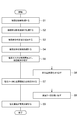
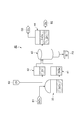
本実施形態の金属ケイ素及び多孔質炭素の製造方法では、籾殻から金属ケイ素及び多孔質炭素を製造する。図1及び図2は、一実施形態に係る金属ケイ素及び多孔質炭素の製造方法の主要な工程を示す図である。図1に示すように、本実施形態の製造方法は、籾殻を加熱処理する工程S1と、籾殻炭を酸性溶液で処理する工程S2と、籾殻炭を粉砕及び成形する工程S3と、籾殻炭体を加熱処理する工程S4と、塩素ガス(Cl2ガス)を含む加熱雰囲気中に籾殻炭体を曝す工程S5と、多孔質炭素(C)を取り出す工程S6と、四塩化ケイ素(SiCl4)と金属亜鉛(Zn)とを反応させる工程S7と、金属ケイ素(Si)を取り出す工程S8と、塩化亜鉛(ZnCl2)を電気分解する工程S9とを有している。そして、これら工程S1~工程S9を繰り返し行うことにより、多孔質炭素及び金属ケイ素を連続的に生産する。
In the method for producing metal silicon and porous carbon of the present embodiment, metal silicon and porous carbon are produced from rice husks. FIG.1 and FIG.2 is a figure which shows the main processes of the manufacturing method of the metal silicon and porous carbon which concern on one Embodiment. As shown in FIG. 1, the manufacturing method of the present embodiment includes a step S1 for heat treating rice husk, a step S2 for treating rice husk charcoal with an acidic solution, a step S3 for pulverizing and shaping rice husk charcoal, and a rice husk charcoal body. Step S4 for heat treating, Step S5 for exposing rice husk charcoal in a heating atmosphere containing chlorine gas (Cl 2 gas), Step S6 for removing porous carbon (C), Silicon tetrachloride (SiCl 4 ), a step S7 reacting a metal zinc (Zn), and step S8 taking out the metal silicon (Si), and zinc chloride (ZnCl 2) and an electrolysis of step S9. Then, by repeatedly performing these steps S1 to S9, porous carbon and metallic silicon are continuously produced.
籾殻を加熱処理する工程S1(第1の工程)では、籾殻に含まれるケイ素(Si)を酸化させて酸化ケイ素(SiO2)と炭素(C)とを主成分とする籾殻炭を生成する。籾殻炭は、約50%重量比のSiO2と、約40%重量比のCを含んでいる。籾殻炭は、SiO2及びCの他に、例えば、水素、窒素、カリウム、カルシウム、ナトリウム、マンガン、鉄、亜鉛等の混合物を含んでいる。混合物の多くは、カリウム、カルシウム、ナトリウムなどのアルカリ金属類である。
In step S1 (first step) of heat treating rice husk, silicon (Si) contained in the rice husk is oxidized to produce rice husk charcoal containing silicon oxide (SiO 2 ) and carbon (C) as main components. Rice husk charcoal contains about 50% by weight SiO 2 and about 40% by weight C. Rice husk charcoal contains, for example, a mixture of hydrogen, nitrogen, potassium, calcium, sodium, manganese, iron, zinc and the like in addition to SiO 2 and C. Many of the mixtures are alkali metals such as potassium, calcium and sodium.
図3は、工程S1~工程S3において用いられる籾殻処理装置10の構成を概略的に示す図である。籾殻処理装置10は、籾殻M1(図4の(a)部参照)を貯蔵する貯蔵部11と、炭化炉12と、炭化炉12に処理ガスG1を供給するガス供給部13と、炭化炉12に冷却水W1を供給する水供給部14と、籾殻炭M2(図4の(b)部参照)を処理するための溶液処理部15と、溶液処理された籾殻炭M2をペレット状に加工するための成形部16を備えている。
FIG. 3 is a diagram schematically showing the configuration of the rice husk processing apparatus 10 used in steps S1 to S3. The rice husk processing apparatus 10 includes a storage unit 11 that stores rice husk M1 (see part (a) of FIG. 4), a carbonization furnace 12, a gas supply unit 13 that supplies a processing gas G1 to the carbonization furnace 12, and a carbonization furnace 12 The water supply unit 14 for supplying the cooling water W1, the solution processing unit 15 for processing rice husk charcoal M2 (see part (b) of FIG. 4), and the solution-treated rice husk charcoal M2 are processed into pellets. For this purpose, a molding part 16 is provided.
炭化炉12は、籾殻M1を収容する加熱処理部12aと、加熱処理部12a内の籾殻M1を加熱するためのヒーター12bとを備えている。また、炭化炉12は、加熱処理部12aで処理された籾殻M1の燃焼を停止させる冷却部12cを備えている。冷却部12cには、水供給部14から冷却水W1が供給され、籾殻M1は冷却部12cにおいて所定の温度まで冷却される。ガス供給部13は、炭化炉12の加熱処理部12aに対して処理ガスG1を供給する。処理ガスG1は、籾殻M1に含まれるSi及びCとの反応性が低いガスである。
The carbonization furnace 12 includes a heat treatment unit 12a that accommodates the rice husk M1 and a heater 12b for heating the rice husk M1 in the heat treatment unit 12a. Further, the carbonization furnace 12 includes a cooling unit 12c that stops combustion of the rice husk M1 processed by the heat processing unit 12a. Cooling water W1 is supplied from the water supply unit 14 to the cooling unit 12c, and the rice husk M1 is cooled to a predetermined temperature in the cooling unit 12c. The gas supply unit 13 supplies the processing gas G <b> 1 to the heat processing unit 12 a of the carbonization furnace 12. The processing gas G1 is a gas having low reactivity with Si and C contained in the rice husk M1.
工程S1では、まず、貯蔵部11から炭化炉12へ籾殻M1が供給され、籾殻M1が炭化炉12の加熱処理部12aへ収容される。次に、ガス供給部13から加熱処理部12aに処理ガスG1を供給しつつ、ヒーター12bを用いて籾殻M1を加熱する。本実施形態では処理ガスG1はN2などの不活性ガス、籾殻M1の完全燃焼に不十分な量の大気ガスであり、籾殻M1は500℃~1000℃の加熱雰囲気中に曝される。籾殻M1は、籾殻M1が完全燃焼するために必要な酸素が不足した雰囲気中で加熱されるので、いわゆる蒸し焼きである不完全燃焼をする。加熱された籾殻M1は、冷却部12cに移動され、所定の温度まで冷却される。そして、加熱処理された後に冷却された籾殻M1は、籾殻炭M2となり、溶液処理部15に移動される。
In step S <b> 1, first, the rice husk M <b> 1 is supplied from the storage unit 11 to the carbonization furnace 12, and the rice husk M <b> 1 is accommodated in the heat treatment unit 12 a of the carbonization furnace 12. Next, the rice husk M1 is heated using the heater 12b while supplying the processing gas G1 from the gas supply unit 13 to the heat processing unit 12a. In this embodiment, the processing gas G1 is an inert gas such as N 2 and an air gas in an amount insufficient for complete combustion of the rice husk M1, and the rice husk M1 is exposed to a heating atmosphere of 500 ° C. to 1000 ° C. The rice husk M1 is heated in an atmosphere that lacks oxygen necessary for the rice husk M1 to burn completely, and thus performs incomplete combustion which is so-called steaming. The heated rice husk M1 is moved to the cooling unit 12c and cooled to a predetermined temperature. Then, the rice husk M1 cooled after the heat treatment becomes rice husk charcoal M2, and is moved to the solution processing unit 15.
籾殻炭中のSiO2と炭素の比率は、以降の反応での量論関係から重要なパラメータとなる。炭素とSiO2のモル数の比率が3倍より小さい場合、その後の反応でもSiO2が残留し多孔質炭素中の不純物となる。それ故、炭素とSiO2のモル数の比率はSiO2+3C→SiC+2COの反応量論比である3倍以上である必要がある。ただしあまり多い場合は、多孔質炭素の細孔分布が所定の分布をとれなくなるので多くても4倍程度にしておくことがよい。
The ratio between SiO 2 and carbon in the rice husk charcoal is an important parameter from the stoichiometric relationship in the subsequent reaction. When the ratio of the number of moles of carbon and SiO 2 is less than 3 times, SiO 2 remains in the subsequent reaction and becomes an impurity in the porous carbon. Therefore, the ratio of the number of moles of carbon and SiO 2 needs to be 3 times or more which is the reaction stoichiometric ratio of SiO 2 + 3C → SiC + 2CO. However, if the number is too large, the pore distribution of the porous carbon cannot take a predetermined distribution.
籾殻炭M2を酸性溶液で処理する工程S2を実施する。工程S2では、炭化炉12で製造された籾殻炭M2を溶液処理部15で処理して、籾殻炭M2に含まれているアルカリ成分やリン等の不純物を除去する。本実施形態では、塩酸(HCl)等の酸性溶液を用いて籾殻炭M2を処理する。
Step S2 of treating rice husk charcoal M2 with an acidic solution is performed. In step S2, rice husk charcoal M2 produced in carbonization furnace 12 is processed by solution processing unit 15 to remove impurities such as alkali components and phosphorus contained in rice husk charcoal M2. In this embodiment, rice husk charcoal M2 is treated using an acidic solution such as hydrochloric acid (HCl).
ところで、炭化ケイ素は研磨剤や耐熱材として求められているので、粒子径の均一性や粒子の緻密性が要求される。一方、多孔質性等の機能を炭化ケイ素に付与可能な製造方法は確立されているが、工業用の炭化ケイ素として用いるためには、十分な特性が得られていない。従って、緻密体にするために行われる高圧処理や、添加物の添加等の処理が必要になる。
By the way, since silicon carbide is required as an abrasive or a heat-resistant material, it is required to have a uniform particle diameter and a dense particle. On the other hand, a manufacturing method capable of imparting functions such as porosity to silicon carbide has been established, but sufficient characteristics have not been obtained for use as industrial silicon carbide. Therefore, a high-pressure process performed to form a dense body and a process such as addition of an additive are required.
本実施形態では、籾殻炭M2を粉砕及び成形する工程S3を実施する。溶液処理部15で処理された籾殻炭M2は成形部16において所定の形状を有する籾殻炭体M3に成形される。成形部16では、まず、籾殻M1の形状を保持した状態の籾殻炭M2を粉砕する。粉砕された籾殻炭M2の平均粒径は、0.1μm~10μmである。この粉砕により籾殻炭M2を構成する粒子の粒子径が一定値に制御されるので、後工程の処理プロセスを安定化することができる。そして、粉砕された籾殻炭M2を、例えばペレット状に籾殻炭体M3を成形する。この成形により、籾殻炭体M3の搬送が容易になる。なお、この工程S3は、必要に応じて実施すればよく、籾殻炭M2を籾殻炭体M3に成形することなく、籾殻炭M2を後工程で利用してもよい。引き続く説明では、籾殻炭体M3について説明する。
In the present embodiment, step S3 of pulverizing and forming rice husk charcoal M2 is performed. The rice husk charcoal M2 processed by the solution processing unit 15 is formed into a rice husk charcoal body M3 having a predetermined shape in the molding unit 16. In the molding unit 16, first, the rice husk charcoal M2 in a state where the shape of the rice husk M1 is maintained is pulverized. The average particle diameter of the crushed rice husk charcoal M2 is 0.1 μm to 10 μm. Since the particle diameter of the particles constituting the rice husk charcoal M2 is controlled to a constant value by this pulverization, the subsequent process can be stabilized. Then, the crushed rice husk charcoal M2 is formed into a rice husk charcoal body M3 in a pellet form, for example. This molding facilitates the conveyance of the rice husk charcoal body M3. In addition, what is necessary is just to implement this process S3, and you may utilize rice husk charcoal M2 in a post process, without shape | molding rice husk charcoal M2 to the rice husk charcoal body M3. In the following description, the rice husk charcoal body M3 will be described.
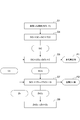
籾殻炭体M3を加熱処理する工程S4(第2の工程)では、籾殻炭体M3に含まれるSiO2とCとを相互に反応させて炭化ケイ素(SiC)を生成する。図2には、この工程S4の反応を示す化学式(1)が示されている。なお、この反応における自由エネルギはΔG=-77kJである。
SiO2+3C→SiC+2CO・・・(1)
In step S4 (second step) of heat-treating rice husk carbon body M3, SiO 2 and C contained in rice husk carbon body M3 are reacted with each other to generate silicon carbide (SiC). FIG. 2 shows a chemical formula (1) indicating the reaction in step S4. The free energy in this reaction is ΔG = −77 kJ.
SiO 2 + 3C → SiC + 2CO (1)
なお、上記化学式(1)の反応は、加熱雰囲気が1700℃以下の温度では処理ガスG2を還元性ガスとすることにより、反応をより促進することができる。上記化学式(1)の反応は、1700℃以下では標準生成自由エネルギが正になっているので反応が進行しにくいが、処理ガスG2がH2やCOなどを含有し、還元性ガスとすることにより、SiCが生成される反応が促進される。一方、加熱雰囲気が1700℃以上の温度では処理ガスG2を還元性ガスとしなくてもよい。
Note that the reaction of the chemical formula (1) can be further promoted by using the processing gas G2 as a reducing gas when the heating atmosphere is 1700 ° C. or lower. The reaction of the above chemical formula (1) is difficult to proceed because the standard free energy of formation is positive at 1700 ° C. or lower, but the processing gas G2 contains H 2 , CO, etc., and is a reducing gas. Thus, the reaction for generating SiC is promoted. On the other hand, when the heating atmosphere is at a temperature of 1700 ° C. or higher, the processing gas G2 may not be a reducing gas.
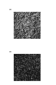
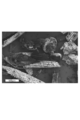
なお、処理雰囲気ガスをN2とした場合、SiO蒸気とN2が反応しSi3N4、SiON2などの窒化物を形成する場合がある。この反応抑制するには、N2の供給量を少なくする、または、希ガスであり反応に寄与しないArやHeを雰囲気ガスとする必要がある。図11Aは、原料のSiO2のモル数とカーボンのモル数とのモル比が1:3.1(すなわち、カーボンのモル数がSiO2のモル数の3.1倍)の籾殻炭を用い、雰囲気ガスをHeとして1550℃で常圧下処理した生成物のX線回折(XRD)波形を示す。横軸は、回折角度、縦軸は、回折強度(単位はCPS(カウント数))である。主生成物はβ型炭化ケイ素であり、少量のグラファイトが形成されている。図11Bは、図11Aの場合と同一原料で、雰囲気ガスをN2とした場合であるが、SiCの形成以外にSi3N4の生成が認められる。図12に図11AのXRD波形に示した生成物の顕微鏡写真を示すが、籾殻構造が残留していることがわかる。
When the processing atmosphere gas is N 2 , SiO vapor and N 2 may react to form nitrides such as Si 3 N 4 and SiON 2 in some cases. In order to suppress this reaction, it is necessary to reduce the supply amount of N 2 or to use Ar or He which is a rare gas and does not contribute to the reaction as an atmospheric gas. FIG. 11A uses rice husk charcoal having a molar ratio of the raw material SiO 2 mole to the carbon mole number of 1: 3.1 (that is, the carbon mole number is 3.1 times the SiO 2 mole number). FIG. 2 shows an X-ray diffraction (XRD) waveform of a product treated under atmospheric pressure at 1550 ° C. using He as the atmospheric gas. The horizontal axis represents the diffraction angle, and the vertical axis represents the diffraction intensity (unit: CPS (count number)). The main product is β-type silicon carbide, and a small amount of graphite is formed. FIG. 11B shows a case where the same raw material as in FIG. 11A is used and the atmosphere gas is N 2 , but generation of Si 3 N 4 is observed in addition to the formation of SiC. FIG. 12 shows a micrograph of the product shown in the XRD waveform of FIG. 11A. It can be seen that the rice husk structure remains.
また、上記化学式(1)の反応ではCOガスが発生するため、反応炉21内の圧力を減圧することにより、一層反応が促進される。さらに、反応炉21内の圧力を減圧することにより、低い蒸気圧を有する金属アルカリ(Na,K)、リン化合物(P2O5,P4)といったアルカリやリンなどの不純物が除去される。
Further, since CO gas is generated in the reaction represented by the chemical formula (1), the reaction is further promoted by reducing the pressure in the reaction furnace 21. Furthermore, by reducing the pressure in the reaction furnace 21, impurities such as alkali and phosphorus such as metal alkali (Na, K) and phosphorus compounds (P 2 O 5 , P 4 ) having a low vapor pressure are removed.
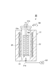
図5及び図6は、工程S4において用いられる籾殻炭体M3の処理装置20の構成を概略的に示す図である。図5を参照すると、処理装置20は、上下方向に延びる反応炉21と、反応炉21の側壁に埋め込まれたヒーター22と、反応炉21内に配置された載置棚23とを備えている。載置棚23には、複数の籾殻炭体M3が個々の段に載置される。この実施形態では、載置棚23は、支持棒23aによって上方から吊り下げて支持されている。
FIG.5 and FIG.6 is a figure which shows schematically the structure of the processing apparatus 20 of the chaff coal body M3 used in process S4. Referring to FIG. 5, the processing apparatus 20 includes a reaction furnace 21 extending in the vertical direction, a heater 22 embedded in the side wall of the reaction furnace 21, and a mounting shelf 23 disposed in the reaction furnace 21. . On the mounting shelf 23, a plurality of rice husk charcoal bodies M3 are mounted on individual stages. In this embodiment, the mounting shelf 23 is supported by being suspended from above by a support bar 23a.
反応炉21の下部には吸気口21aが設けられており、この吸気口21aから第1不活性ガスや還元性ガスである処理ガスG2が導入される。処理ガスG2は、H2,N2,Ar,He,COの少なくとも一つを含むガスを用いることができる。処理ガスG2には、H2ガスが利用できる。H2ガスによれば、SiO2とH2との反応により生成された一酸化ケイ素(SiO)により上記化学式(1)の反応を促進することができる。この処理ガスG2は、反応炉21内を上方へ移動したのち、反応炉21の上部に設けられた排気口21bから排出される。ヒーター22は載置棚23の周囲を囲むように配置されており、載置棚23に載置された籾殻炭体M3を加熱する。
An intake port 21a is provided in the lower part of the reaction furnace 21, and a processing gas G2 that is a first inert gas or a reducing gas is introduced from the intake port 21a. As the processing gas G2, a gas containing at least one of H 2 , N 2 , Ar, He, and CO can be used. H 2 gas can be used as the processing gas G2. According to the H 2 gas, the reaction represented by the chemical formula (1) can be promoted by silicon monoxide (SiO) generated by the reaction between SiO 2 and H 2 . The processing gas G <b> 2 moves upward in the reaction furnace 21 and is then discharged from an exhaust port 21 b provided in the upper part of the reaction furnace 21. The heater 22 is disposed so as to surround the mounting shelf 23, and heats the rice husk charcoal body M <b> 3 mounted on the mounting shelf 23.
工程S4では、まず、載置棚23に籾殻炭体M3を載置する。次に、吸気口21aから反応炉21内に処理ガスG2を供給しつつ、ヒーター22を用いて処理ガスG2を加熱する。本実施形態では処理ガスG2はH2ガスであり、籾殻炭体M3は1200℃以上2000℃以下の加熱雰囲気中に2~10時間曝される。また、反応炉21内は、例えば1気圧未満の圧力に設定される。この加熱により、化学式(1)の反応が生じ、籾殻炭体M3から籾殻炭体M4が生成される(図6参照)。籾殻炭体M4は、SiCを含む。このSiCと同時に生成された一酸化炭素(CO)は、処理ガスG2と共に反応炉21の上部に設けられた排気口21bから排出される。加熱終了後、載置棚23から籾殻炭体M4を取り出す。
In step S4, first, the rice husk charcoal body M3 is placed on the placing shelf 23. Next, the processing gas G2 is heated using the heater 22 while supplying the processing gas G2 into the reaction furnace 21 from the intake port 21a. In this embodiment, the processing gas G2 is H 2 gas, and the rice husk charcoal body M3 is exposed to a heated atmosphere of 1200 ° C. or higher and 2000 ° C. or lower for 2 to 10 hours. Moreover, the inside of the reaction furnace 21 is set to a pressure of, for example, less than 1 atmosphere. By this heating, the reaction of the chemical formula (1) occurs, and rice husk coal M4 is generated from rice husk coal M3 (see FIG. 6). Rice hull charcoal M4 contains SiC. Carbon monoxide (CO) generated simultaneously with the SiC is discharged together with the processing gas G2 from an exhaust port 21b provided in the upper part of the reaction furnace 21. After the heating, the rice husk charcoal body M4 is taken out from the mounting shelf 23.
次に、塩素ガス(Cl2)を含む加熱雰囲気中に籾殻炭体M4を曝す工程S5(第3の工程)を実施する。工程S5では、SiとCとの化合物であるSiCと、Cl2ガスとを互いに接触させて加熱処理を行うことにより、籾殻炭体M4から多孔質炭素P1を生成する。図2には、この工程S5の反応を示す化学式(2)が示されている。なお、この反応における自由エネルギはΔG=-430kJである。
SiC+2Cl2→SiCl4+C・・・(2)
Next, step S5 (third step) of exposing rice husk charcoal body M4 in a heated atmosphere containing chlorine gas (Cl 2 ) is performed. In step S5, porous carbon P1 is generated from rice husk coal M4 by performing heat treatment by bringing SiC, which is a compound of Si and C, and Cl 2 gas into contact with each other. FIG. 2 shows a chemical formula (2) indicating the reaction in step S5. The free energy in this reaction is ΔG = −430 kJ.
SiC + 2Cl 2 → SiCl 4 + C (2)
この工程S5では、SiCのSiとCl2ガスとが反応してSiCl4が生成されてSiCからSiが抜け出る。この反応により、籾殻炭体M4からSiが抜け出て、多孔質の炭素構造を有する多孔質炭素P1が形成される。また、工程S5では、多孔質炭素P1と共に、SiCl4が得られる。このSiCl4は、例えば冷却器などにおいて室温付近まで冷却されることにより回収される。
In this step S5, SiC Si and Cl 2 gas react to generate SiCl 4, and Si escapes from SiC. By this reaction, Si escapes from the rice husk coal body M4 to form porous carbon P1 having a porous carbon structure. In step S5, SiCl 4 is obtained together with the porous carbon P1. This SiCl 4 is recovered by being cooled to near room temperature in a cooler, for example.
図7及び図8は、工程S5において用いられる籾殻炭体M4の処理装置30の構成を概略的に示す図である。籾殻炭体M4の処理装置30は、例えば光ファイバの多孔質母材の脱水処理に用いられる脱水焼結炉を用いることができる。図7を参照すると、処理装置30としては、反応炉31と、冷却トラップ32と、貯留タンク33とを備えている。
FIG.7 and FIG.8 is a figure which shows schematically the structure of the processing apparatus 30 of the chaff coal body M4 used in process S5. The processing device 30 for the rice husk charcoal body M4 can use, for example, a dehydration sintering furnace used for dehydration processing of a porous preform of an optical fiber. Referring to FIG. 7, the processing apparatus 30 includes a reaction furnace 31, a cooling trap 32, and a storage tank 33.
反応炉31は、載置棚31aを備えている。載置棚31aには、複数の籾殻炭体M4が個々の段に載置される。載置棚31aは支持棒31bによって上方から吊り下げて支持されている。反応炉31における載置棚31aよりも下の部分にはガス導入口31cが設けられている。このガス導入口31cからは、処理ガスG3が反応炉31に供給される。本実施形態の処理ガスG3は、Cl2ガスと第2不活性ガスとの混合ガス、若しくは実質的に100%のCl2ガスである。本実施形態では、第2不活性ガスとして、窒素(N2)、アルゴン(Ar)、ヘリウム(He)等を用いることができる。
The reaction furnace 31 includes a mounting shelf 31a. On the mounting shelf 31a, a plurality of rice husk charcoal bodies M4 are mounted on individual stages. The mounting shelf 31a is supported by being suspended from above by a support bar 31b. A gas inlet 31c is provided in a portion of the reaction furnace 31 below the mounting shelf 31a. The processing gas G3 is supplied to the reaction furnace 31 from the gas inlet 31c. The processing gas G3 of the present embodiment is a mixed gas of Cl 2 gas and the second inert gas, or substantially 100% Cl 2 gas. In the present embodiment, nitrogen (N 2 ), argon (Ar), helium (He), or the like can be used as the second inert gas.
反応炉31の外側には、載置棚31aを囲むようにヒーター31dが設けられている。このヒーター31dにより、籾殻炭体M4の周囲のCl2ガスを含む雰囲気が例えば1000℃以上1600℃以下の温度となるように加熱される。反応炉31の上部には、ガス排出口31eが設けられている。ガス排出口31eは冷却トラップ32に接続されている。この冷却トラップ32内を循環する冷媒32aによって、反応炉31からの排気が、例えばマイナス10℃以下に冷却される。Cl2ガスの沸点はマイナス34℃であるので、SiCl4と容易に分離される。
A heater 31d is provided outside the reaction furnace 31 so as to surround the mounting shelf 31a. The heater 31d heats the atmosphere containing the Cl 2 gas around the rice husk coal body M4 to a temperature of 1000 ° C. or higher and 1600 ° C. or lower, for example. A gas discharge port 31 e is provided in the upper part of the reaction furnace 31. The gas discharge port 31 e is connected to the cooling trap 32. The exhaust gas from the reaction furnace 31 is cooled to, for example, minus 10 ° C. or less by the refrigerant 32 a circulating in the cooling trap 32. Since the boiling point of Cl 2 gas is minus 34 ° C., it is easily separated from SiCl 4 .
工程S5では、まず、載置棚31aに籾殻炭体M4を載置する。次に、ガス導入口31cから反応炉31内に処理ガスG3を供給しつつ、ヒーター31dを用いて処理ガスG3を加熱する。本実施形態では、処理ガスG3はCl2ガスであり、籾殻炭体M4は1000℃以上1600℃以下又は1100℃以上1300℃以下の温度の加熱雰囲気中に60~600分間曝される。この加熱により、図8に示される化学式(2)の反応が生じて、SiCからSiが抜け、載置棚31aにおいて多孔質炭素P1が生成される。工程S5の後に、載置棚31aから多孔質炭素P1を取り出す(工程S6)。
In step S5, the rice husk charcoal body M4 is first mounted on the mounting shelf 31a. Next, the processing gas G3 is heated using the heater 31d while supplying the processing gas G3 into the reaction furnace 31 from the gas inlet 31c. In this embodiment, the processing gas G3 is Cl 2 gas, and the rice husk charcoal body M4 is exposed to a heating atmosphere at a temperature of 1000 ° C. to 1600 ° C. or 1100 ° C. to 1300 ° C. for 60 to 600 minutes. By this heating, the reaction of the chemical formula (2) shown in FIG. 8 occurs, Si is released from SiC, and porous carbon P1 is generated in the mounting shelf 31a. After step S5, the porous carbon P1 is taken out from the mounting shelf 31a (step S6).
また、化学式(2)の反応により生じたSiCl4及び処理ガスG3は、ガス排出口31eから反応炉31の外部の冷却トラップ32へ排出される。そして、冷却トラップ32で液化されたSiCl4は、貯留タンク33に貯留されたのち、還元装置40(図9及び図10参照)へ送られる(図8の参照符号B1)。また、冷却トラップ32を通過した処理ガスG3は、三方弁34を介して、籾殻炭体M4の処理装置30の外部へ排気されるか、若しくは再び反応炉31のガス導入口31cへ送られる。
Further, SiCl 4 and the processing gas G3 generated by the reaction of the chemical formula (2) are discharged from the gas discharge port 31e to the cooling trap 32 outside the reaction furnace 31. The SiCl 4 liquefied by the cooling trap 32 is stored in the storage tank 33 and then sent to the reduction device 40 (see FIGS. 9 and 10) (reference numeral B1 in FIG. 8). Further, the processing gas G3 that has passed through the cooling trap 32 is exhausted to the outside of the processing device 30 for the rice husk coal body M4 via the three-way valve 34 or is sent to the gas inlet 31c of the reaction furnace 31 again.
SiCとCl2の反応により、SiCからSiが抜け出て、空隙領域に気孔が形成される。化学式(2)の反応は1000℃以上の温度でよく進むが、得られた多孔質炭素P1の比表面積は温度依存性を有し、比表面積が大きい多孔質炭素P1は活性炭として有効に活用可能である。比表面積は1150℃~1250℃の処理で最大値をとり、その値は1500m2/g~1700m2/gとなった。1400℃以上の処理では活性炭の組織が、アモルファスからグラファイトに変換し表面積が800~1000m2/gに低下した。ただし、グラファイト構造を必要とする活性炭には有効である。
Due to the reaction between SiC and Cl 2 , Si escapes from SiC and pores are formed in the void region. Although the reaction of chemical formula (2) proceeds well at a temperature of 1000 ° C. or higher, the specific surface area of the obtained porous carbon P1 has temperature dependence, and the porous carbon P1 having a large specific surface area can be effectively used as activated carbon. It is. The specific surface area was maximized by treatment at 1150 ° C. to 1250 ° C., and the value was 1500 m 2 / g to 1700 m 2 / g. In the treatment at 1400 ° C. or higher, the activated carbon structure changed from amorphous to graphite, and the surface area decreased to 800 to 1000 m 2 / g. However, it is effective for activated carbon that requires a graphite structure.
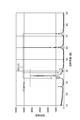
Cl2ガス雰囲気で1100℃処理で得られた多孔質炭素材料のX線回折波形を図13に示す。横軸は回折角度、縦軸は回折強度(単位はCPS(カウント数))である。主生成物はSiCを処理した場合に特徴的な、15°未満の小角散乱、20°付近のブロードな回折とグラファイト01面に起因する43°付近の回折が確認される。また、少量のグラファイトが形成されていることが26°の回折線より確認できる。
FIG. 13 shows an X-ray diffraction waveform of a porous carbon material obtained by treatment at 1100 ° C. in a Cl 2 gas atmosphere. The horizontal axis represents the diffraction angle, and the vertical axis represents the diffraction intensity (unit: CPS (count number)). The main product is confirmed to have a small-angle scattering of less than 15 °, a broad diffraction around 20 °, and a diffraction around 43 ° due to the graphite 01 plane, which are characteristic when SiC is treated. Moreover, it can be confirmed from the diffraction line of 26 ° that a small amount of graphite is formed.
なお、籾殻炭体M4中に微量の金属不純物が存在しても、工程S5の処理において、SiCl4の蒸気圧が他の金属塩化物に対して十分に高い値であるので、SiCl4を凝縮させるときに金属不純物の混入は無視できる。
Even if there is trace metal impurities in the chaff Sumitai M4, in the processing of step S5, since the vapor pressure of the SiCl 4 is a sufficiently high value with respect to other metal chlorides, condensed SiCl 4 When mixed, metal impurities are negligible.
SiCl4とZnとを反応させる工程S7(第4の工程)では、いわゆる亜鉛還元法を用いて、SiCl4から高純度の金属ケイ素P2(Si)を取り出す。より詳細には、工程S5で生成されたSiCl4に含まれるCl2とZnとを相互に反応させることにより、SiCl4を還元させて金属ケイ素P2(Si)を生成する。Znは、SiCl4との組み合わせにおいて、Siと固溶体を作らず、塩化亜鉛の融点が比較的低く、塩化亜鉛の蒸気圧も高い点から、選択される材料である。図2には、この工程S7の反応を示す化学式(3)が示されている。なお、この反応における自由エネルギはΔG=-64kJである。
SiCl4+2Zn→2ZnCl2+Si・・・(3)
In step S7 (fourth step) in which SiCl 4 and Zn are reacted, high-purity metallic silicon P2 (Si) is extracted from SiCl 4 using a so-called zinc reduction method. More specifically, by reacting Cl 2 and Zn contained in SiCl 4 produced in step S5 with each other, SiCl 4 is reduced to produce metallic silicon P2 (Si). Zn is a material selected in combination with SiCl 4 because it does not form a solid solution with Si, the melting point of zinc chloride is relatively low, and the vapor pressure of zinc chloride is high. FIG. 2 shows a chemical formula (3) showing the reaction in step S7. The free energy in this reaction is ΔG = −64 kJ.
SiCl 4 + 2Zn → 2ZnCl 2 + Si (3)
また、工程S7では、SiCl4とZnとを気相で反応させる。Znの沸点は907℃と金属の中では比較的低く、800℃近傍でも供給に気化可能な蒸気圧を有している。上記の気相反応で生成されるZnCl2の沸点は756℃であるので、SiCl4との反応はZnCl2が析出しない800℃以上の温度であることができる。
In step S7, SiCl 4 and Zn are reacted in the gas phase. The boiling point of Zn is 907 ° C., which is relatively low among metals, and has a vapor pressure that can be vaporized even in the vicinity of 800 ° C. Since the boiling point of ZnCl 2 produced by the above gas phase reaction is 756 ° C., the reaction with SiCl 4 can be performed at a temperature of 800 ° C. or higher at which ZnCl 2 does not precipitate.
工程S9(第5の工程)では、ZnCl2を電気分解する。この電気分解でZnCl2からZnとCl2ガスとが生成される。
図2には、この工程S9の反応を示す化学式(4)が示されている。なお、この反応における自由エネルギはΔG=+323kJある。
ZnCl2 → Zn+Cl2・・・(4)
In step S9 (fifth step), ZnCl 2 is electrolyzed. By this electrolysis, Zn and Cl 2 gas are generated from ZnCl 2 .
FIG. 2 shows a chemical formula (4) showing the reaction in this step S9. The free energy in this reaction is ΔG = + 323 kJ.
ZnCl 2 → Zn + Cl 2 (4)
この工程S9では、例えばZnCl2を高温溶融状態での電気分解により、ZnCl2からZnとCl2ガスとを生成する。そして、この工程S9によって生成されたCl2ガスは、前述した工程S5において再び用いられる(図2参照)。更に、この工程S9によって生成されたZnは、前述した工程S7において再び用いられる(図2参照)。
In this step S9, for example, ZnCl 2 gas is generated from ZnCl 2 by electrolysis of ZnCl 2 in a high-temperature molten state. The Cl 2 gas generated in this step S9 is used again in the above-described step S5 (see FIG. 2). Furthermore, Zn produced | generated by this process S9 is used again in process S7 mentioned above (refer FIG. 2).
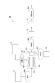
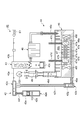
図9及び図10は、工程S7,S8,S9において用いられる還元装置40の構成を概略的に示す図である。図9は還元装置40の構成を簡略化して示す図であり、図10は還元装置40の具体的な構成を示す図である。
9 and 10 are diagrams schematically showing a configuration of the reduction device 40 used in steps S7, S8, and S9. FIG. 9 is a diagram illustrating a simplified configuration of the reduction device 40, and FIG. 10 is a diagram illustrating a specific configuration of the reduction device 40.
図9を参照すると、還元装置40は、気化器41及び気化器42と、反応炉43と、電気分解槽44とを備えている。上述した籾殻炭体M4の処理装置30の貯留タンク33に貯留されたSiCl4(参照符号B1)は、気化器41に送られて気化する。一方、気化器42では、Znが気化される。気化したSiCl4及びZnは、反応炉43に送られる。そして、反応炉43においてSiCl4及びZnを高温で反応させる。この反応により前述した化学式(3)の反応が生じ、金属ケイ素P2及びZnCl2が生成される。
Referring to FIG. 9, the reduction device 40 includes a vaporizer 41 and a vaporizer 42, a reaction furnace 43, and an electrolysis tank 44. The SiCl 4 (reference symbol B1) stored in the storage tank 33 of the processing device 30 for the rice husk coal body M4 described above is sent to the vaporizer 41 and vaporized. On the other hand, in the vaporizer 42, Zn is vaporized. The vaporized SiCl 4 and Zn are sent to the reaction furnace 43. Then, SiCl 4 and Zn are reacted at a high temperature in the reaction furnace 43. The reaction occurs in the above-mentioned chemical formula by the reaction (3), metal silicon P2 and ZnCl 2 are generated.
ZnCl2は、融点(280℃)以上の温度、沸点未満でトラップされ、電気分解槽44に送られる。そして、ZnCl2は、直流電流による電気分解により化学式(4)の反応が生じ、ZnCl2がZnとCl2ガスとに分離される。生成されたCl2ガスは処理ガスG3として籾殻炭体M4の処理装置30に送られ(図8及び図9のG3)、Znは気化器42に送られる(図9の参照符号B2)。
ZnCl 2 is trapped at a temperature not lower than the melting point (280 ° C.) and lower than the boiling point, and is sent to the electrolysis tank 44. ZnCl 2 undergoes a reaction of chemical formula (4) by electrolysis with a direct current, and ZnCl 2 is separated into Zn and Cl 2 gas. The generated Cl 2 gas is sent as the processing gas G3 to the processing device 30 of the rice husk coal body M4 (G3 in FIGS. 8 and 9), and Zn is sent to the vaporizer 42 (reference numeral B2 in FIG. 9).
図10を参照して、具体的な還元装置40について説明する。この還元装置40では、気化器42が、系内投入用気化器42aと、連続運転用気化器42bと、集合管42cとを有している。系内投入用気化器42aはゲート弁42dを有しており、還元装置40の外部からZnを投入することが可能となっている。Znは、系内投入用気化器42aの気化室42eに収容され、気化する。気化室42eと集合管42cとは、配管42fによって互いに連結されている。また、連続運転用気化器42bは、電気分解槽44から取り出されたZnを収容し、気化する亜鉛蒸発部42gを有している。亜鉛蒸発部42gと集合管42cとは、配管42hによって互いに連結されている。
A specific reduction device 40 will be described with reference to FIG. In the reduction device 40, the carburetor 42 includes an in-system carburetor 42a, a continuous operation carburetor 42b, and a collecting pipe 42c. The in-system charging carburetor 42 a has a gate valve 42 d, and Zn can be input from the outside of the reducing device 40. Zn is accommodated in the vaporizing chamber 42e of the in-system charging vaporizer 42a and vaporizes. The vaporizing chamber 42e and the collecting pipe 42c are connected to each other by a pipe 42f. Further, the continuous operation vaporizer 42b has a zinc evaporation part 42g that accommodates and vaporizes Zn taken out from the electrolysis tank 44. The zinc evaporation part 42g and the collecting pipe 42c are connected to each other by a pipe 42h.
系内投入用気化器42a及び連続運転用気化器42bの配管42hは、例えばセラミックス(アルミナ等)によって構成される。また、連続運転用気化器42bの亜鉛蒸発部42g、及び集合管42cは、例えばカーボンによって構成される。系内投入用気化器42a、連続運転用気化器42b、及び集合管42cは、金属亜鉛の蒸気を効率よく発生させるために800℃以上の温度、例えば900℃~1000℃といった高温に加熱される。
The piping 42h of the in-system charging carburetor 42a and the continuous operation carburetor 42b is made of ceramics (alumina or the like), for example. Moreover, the zinc evaporation part 42g and the collecting pipe 42c of the vaporizer 42b for continuous operation are comprised, for example with carbon. The in-system carburetor 42a, the continuous operation carburetor 42b, and the collecting pipe 42c are heated to a temperature of 800 ° C. or higher, for example, 900 ° C. to 1000 ° C., in order to efficiently generate metallic zinc vapor. .
反応炉43は、例えば石英製の容器である。反応炉43の上部は、石英製の配管43aを介して気化器42の集合管42cと連結されており、気化されたZnが配管43aを介して反応炉43へ送られる。また、反応炉43の上部には、石英製の配管43bを介してSiCl4(参照符号B1)が流入する。反応炉43は1200℃~1400℃といった高温に加熱されており、反応炉43の内部において、ZnとSiCl4とが互いに反応する。その結果生じた金属ケイ素P2は、反応炉43の内部に設けられた加熱されていない容器43cに収容される。また、ZnCl2は、金属ケイ素P2の微粒子を除去する為の微粒子トラップ45を通過したのち、電気分解槽44に送られる。微粒子トラップ45は例えば石英製であり、900℃~1000℃といった高温に加熱されている。
The reaction furnace 43 is, for example, a quartz container. The upper part of the reaction furnace 43 is connected to the collecting pipe 42c of the vaporizer 42 through a quartz pipe 43a, and the vaporized Zn is sent to the reaction furnace 43 through the pipe 43a. In addition, SiCl 4 (reference numeral B1) flows into the upper portion of the reaction furnace 43 through a quartz pipe 43b. The reaction furnace 43 is heated to a high temperature of 1200 ° C. to 1400 ° C., and Zn and SiCl 4 react with each other in the reaction furnace 43. The resulting metal silicon P2 is accommodated in an unheated container 43c provided inside the reaction furnace 43. ZnCl 2 passes through a fine particle trap 45 for removing fine particles of metal silicon P 2, and is then sent to the electrolysis tank 44. The fine particle trap 45 is made of, for example, quartz and is heated to a high temperature of 900 ° C. to 1000 ° C.
得られた金属ケイ素P2の純度は、99.9995%といったきわめて高い数値であり、この純度であれば太陽電池用の材料として利用可能である。なお、金属ケイ素P2には、不純物としてZnとO2とが確認された。
The purity of the obtained metal silicon P2 is a very high value such as 99.9995%, and this purity can be used as a material for solar cells. In addition, Zn and O 2 were confirmed as impurities in the metal silicon P2.
電気分解槽44は、本体部46及び電極構造体47を備えている。本体部46は、溶融したZnCl2を収容し、電解するための電解槽46aと、電解槽46aの内部を加熱するための熱源であるヒーター46fとを有する。電解槽46aの上方には空間46bが設けられ、空間46bの水平方向の一端には微粒子トラップ45に連結された配管46cが配置され、他端には配管46d(デミスタ)が配置されている。配管46cから導入されたZnCl2は、電解槽46aへ導かれる。電解槽46aにおいて発生したCl2ガスは、空間46bを通って配管46dから排出され、籾殻炭体M4の処理装置30へ処理ガスG3として供給される。なお、配管46dの先端にはテフロン(登録商標)樹脂製のフィルタ48が設けられている。また、電解槽46aの底部には配管46eが連結されており、電解槽46aの底部に堆積した高純度のZnは、この配管46eを通って連続運転用気化器42bへ送られる。
The electrolysis tank 44 includes a main body 46 and an electrode structure 47. The main body 46 has an electrolytic bath 46a for accommodating and electrolyzing molten ZnCl 2 and a heater 46f as a heat source for heating the inside of the electrolytic bath 46a. A space 46b is provided above the electrolytic cell 46a, a pipe 46c connected to the particulate trap 45 is disposed at one end in the horizontal direction of the space 46b, and a pipe 46d (demister) is disposed at the other end. ZnCl 2 introduced from the pipe 46c is guided to the electrolytic cell 46a. The Cl 2 gas generated in the electrolytic bath 46a is discharged from the pipe 46d through the space 46b, and is supplied as the processing gas G3 to the processing device 30 of the rice husk coal body M4. A filter 48 made of Teflon (registered trademark) resin is provided at the tip of the pipe 46d. A pipe 46e is connected to the bottom of the electrolytic cell 46a, and high-purity Zn deposited on the bottom of the electrolytic cell 46a is sent to the continuous operation vaporizer 42b through the pipe 46e.
電極構造体47は、複数の電極板47aを有する。複数の電極板47aは、隙間をあけて板厚方向に並置され、該板厚方向を水平方向として電解槽46a内に配置されている。複数の電極板47aは、例えば高純度炭素材料といった、高温に強く塩素に対し耐食性を有する導電性物質からなり、水平方向に延設された一または複数の棒状部材47bによって貫通され、相互の位置関係が保持されている。
The electrode structure 47 has a plurality of electrode plates 47a. The plurality of electrode plates 47a are juxtaposed in the plate thickness direction with a gap, and are arranged in the electrolytic cell 46a with the plate thickness direction as a horizontal direction. The plurality of electrode plates 47a are made of a conductive material that is resistant to chlorine and resistant to chlorine, such as a high-purity carbon material, and are penetrated by one or a plurality of rod-shaped members 47b extending in the horizontal direction, so that the mutual positions Relationship is maintained.
複数の電極板47aのうち、水平方向の一端に位置する電極板47aには、該電極板47aと電気的に接続された通電部材47cを介して所定の正電圧が印加され、この電極板47aは陽極として機能する。また、水平方向の他端に位置する電極板47aには、該電極板47aと電気的に接続された通電部材47dを介して所定の負電圧が印加され、この電極板47aは陰極として機能する。これら陽極及び陰極の間に配置された電極板47aには、通電部材を介して、上記した正電圧及び負電圧の間で電位勾配が与えられ、これらの電極板47aはそれぞれ中間電極として機能する。
A predetermined positive voltage is applied to the electrode plate 47a located at one end in the horizontal direction among the plurality of electrode plates 47a via an energization member 47c electrically connected to the electrode plate 47a. Functions as an anode. In addition, a predetermined negative voltage is applied to the electrode plate 47a located at the other end in the horizontal direction via an energization member 47d electrically connected to the electrode plate 47a, and this electrode plate 47a functions as a cathode. . The electrode plate 47a disposed between the anode and the cathode is given a potential gradient between the positive voltage and the negative voltage via the energizing member, and each of these electrode plates 47a functions as an intermediate electrode. .
配管46cから導入されたZnCl2は、電解槽46aに取り込まれる。電解槽46a内はヒーターによって例えば500℃~700℃といったZnの融点よりも高い温度に保たれるので、ZnCl2は溶融状態のまま維持される。
ZnCl 2 introduced from the pipe 46c is taken into the electrolytic cell 46a. Since the inside of the electrolytic cell 46a is maintained at a temperature higher than the melting point of Zn, for example, 500 ° C. to 700 ° C. by the heater, ZnCl 2 is maintained in a molten state.
また、電解槽46aの内部には複数の電極板47aが配置されており、溶融したZnCl2中に複数の電極板47aが浸される。そして、所定の電位差が各電極板47aに与えられると、隣り合う電極板47a同士の対向する面(電解面)を介してZnCl2中に電流が流れ、ZnCl2がCl2とZnとに電気分解される。こうして生成されたZnは、ZnCl2の融液より比重が大きいので電解槽46aの底部に堆積し、配管46eを通って連続運転用気化器42bへ送られる。また、生成されたCl2は、Cl2ガスとなって電解槽46aの上方へ移動し、配管46dを通って籾殻炭体M4の処理装置30へ送られる。
Further, the inside of the electrolytic cell 46a are arranged a plurality of electrode plates 47a, a plurality of electrode plates 47a are immersed in ZnCl 2 were melted. When the predetermined potential difference is applied to the electrode plates 47a, a current flows in ZnCl 2 through the surface (electrolytic surface) facing between adjacent electrode plates 47a, electric ZnCl 2 within Cl 2 and Zn Disassembled. The Zn thus produced has a specific gravity greater than that of the ZnCl 2 melt, and therefore accumulates at the bottom of the electrolytic cell 46a and is sent to the continuous operation vaporizer 42b through the pipe 46e. Further, the generated Cl 2 becomes Cl 2 gas, moves upward of the electrolytic cell 46a, and is sent to the processing device 30 for the rice husk charcoal body M4 through the pipe 46d.
この製造方法では、籾殻M1から、SiO2とCとを含む籾殻炭M2を生成し、この籾殻炭M2からSiCを生成する。次に、SiCとCl2ガスとを反応させて、多孔質炭素P1とSiCl4とを生成する。続いて、SiCl4とZnとを反応させて、金属ケイ素P2とZnCl2とを生成する。そして、電気分解により発生したCl2ガスを多孔質炭素P1の生成に用いると共に、電気分解により発生したZnを金属ケイ素P2の生成に用いる。従って、この製造方法によれば、籾殻M1から多孔質炭素P1と金属ケイ素P2とを製造することができる。
In this manufacturing method, rice husk charcoal M2 containing SiO 2 and C is generated from rice husk M1, and SiC is generated from the rice husk charcoal M2. Next, SiC and Cl 2 gas are reacted to generate porous carbon P1 and SiCl 4 . Subsequently, SiCl 4 and Zn are reacted to generate metallic silicon P 2 and ZnCl 2 . Then, the Cl 2 gas generated by the electrolysis is used for generating the porous carbon P1, and the Zn generated by the electrolysis is used for generating the metal silicon P2. Therefore, according to this manufacturing method, porous carbon P1 and metal silicon P2 can be manufactured from rice husk M1.
また、第2の工程S4の前に酸性溶液で籾殻炭M2を処理する。この工程S4によれば、酸性溶液による処理によって籾殻炭M2に含まれる不純物が除去されるので、籾殻炭M2に含まれるSiO2及びCの純度が高まる。従って、第3の工程S5において不純物と反応するCl2ガスの量が低減されるので、第3の工程S5で必要なCl2ガスの量を低減することができる。
In addition, rice husk charcoal M2 is treated with an acidic solution before the second step S4. According to this step S4, impurities contained in the rice husk charcoal M2 are removed by the treatment with the acidic solution, so that the purity of SiO 2 and C contained in the rice husk charcoal M2 is increased. Therefore, since the amount of Cl 2 gas that reacts with impurities in the third step S5 is reduced, the amount of Cl 2 gas required in the third step S5 can be reduced.
また、第2の工程S4では、処理ガスはH2を含み、処理ガスは1200℃以上2000℃以下の温度に加熱される。1200℃以上2000℃以下の温度範囲では、SiO2とCとの反応が促進されるので、SiCを効率よく生成することができる。また、H2ガスはSiO2とCとの反応を促進させるので、SiCをさらに効率よく生成することができる。
In the second step S4, the process gas comprises H 2, the process gas is heated to temperatures below 2000 ° C. 1200 ° C. or higher. In the temperature range of 1200 ° C. or more and 2000 ° C. or less, the reaction between SiO 2 and C is promoted, so that SiC can be generated efficiently. Further, H 2 gas, so to promote the reaction between the SiO 2 and C, and can be produced more efficiently SiC.
また、第2の工程S4では、SiCの生成は1気圧未満の圧力で行われる。処理容器内の圧力を大気圧未満の圧力に設定することにより、蒸気圧が低い不純物を籾殻炭M2から除去することができる。
In the second step S4, SiC is generated at a pressure of less than 1 atmosphere. By setting the pressure in the processing vessel to a pressure lower than atmospheric pressure, impurities with low vapor pressure can be removed from rice husk charcoal M2.
また、第3の工程S5では、加熱雰囲気はCl2ガスと第2不活性ガスとの混合ガス又は実質的に100%のCl2ガスを含む。このような加熱雰囲気によれば、適正な反応を促進することができる。
In the third step S5, the heating atmosphere contains a mixed gas of Cl 2 gas and the second inert gas or substantially 100% Cl 2 gas. According to such a heating atmosphere, an appropriate reaction can be promoted.
また、第3の工程S5では、Cl2ガスを含む雰囲気を1000℃以上1600℃以下の温度に加熱する。加熱雰囲気が1000℃以上の温度であるので、Cl2ガスとSiCとの反応を促進させることができる。また、加熱雰囲気が1600℃以下の温度であるので、生成される多孔質炭素P1の組織がグラファイト化することを抑制し、多孔質炭素P1の比表面積の減少を抑制できる。
In the third step S5, an atmosphere containing Cl 2 gas is heated to a temperature of 1000 ° C. or higher and 1600 ° C. or lower. Since the heating atmosphere is at a temperature of 1000 ° C. or higher, the reaction between Cl 2 gas and SiC can be promoted. Moreover, since the heating atmosphere is a temperature of 1600 ° C. or lower, it is possible to suppress the structure of the generated porous carbon P1 from being graphitized, and to suppress a decrease in the specific surface area of the porous carbon P1.
また、第4の工程S7は、SiCl4を600℃以上1100℃以下の温度に加熱して、SiCl4のガスを発生させる工程と、SiCl4のガスをZnの蒸気と反応させて、金属ケイ素P2とZnCl2とを生成する工程と、ZnCl2を冷却してZnCl2を液化させる工程と、を含む。SiCl4とZnとの反応を促進させることができる。
The fourth step S7, heats the SiCl 4 at a temperature of 600 ° C. or higher 1100 ° C. or less, a step of generating a gas SiCl 4, and the gas SiCl 4 is reacted with the vapor of Zn, metallic silicon and a step of generating the P2 and ZnCl 2, a step of liquefying the ZnCl 2 was cooled ZnCl 2, a. The reaction between SiCl 4 and Zn can be promoted.
また、第3の工程S5では、SiCl4のガスを、加熱雰囲気中から排出することにより、多孔質炭素P1からSiCl4を分離する。多孔質炭素P1とSiCl4とを容易に分離することができる。
In the third step S5, SiCl 4 is separated from the porous carbon P1 by discharging the SiCl 4 gas from the heated atmosphere. The porous carbon P1 and SiCl 4 can be easily separated.
また、第4の工程S7では、ZnCl2のガスを、加熱雰囲気中から排出することにより、金属ケイ素P1からZnCl2を分離する。金属ケイ素P1とZnCl2を容易に分離することができる。
In the fourth step S7, ZnCl 2 is separated from the metal silicon P1 by discharging a gas of ZnCl 2 from the heating atmosphere. The metallic silicon P1 and ZnCl 2 can be easily separated.
また、本実施形態では、籾殻M1からSiO2を含む籾殻炭M2を生成した後に、SiO2を用いてSiCを生成する。このようにSiO2を含む籾殻炭M2を経てSiCを製造する工程によれば、籾殻炭M2の生成時に不純物を除去する工程S2を追加することができる。従って、籾殻M1の処理中に生じるメタンや一酸化炭素等の大量の有機分解生成ガスを処理する複雑な装置を用いることなく、SiCを含む籾殻炭体M4を生成することができる。また、SiO2を含む籾殻炭M2を生成する第1の工程S1と、SiO2からSiCを生成する第2の工程S4とを組み合わせることにより、装置構成を簡略化できる。
Further, in the present embodiment, after generating the chaff charcoal M2 containing SiO 2 from rice hulls M1, produces a SiC with SiO 2. According to the process of manufacturing the SiC via chaff charcoal M2 containing SiO 2, it is possible to add a step S2 of removing impurities at the time of generation of the rice husk charcoal M2. Therefore, the rice husk charcoal body M4 containing SiC can be produced without using a complicated apparatus for treating a large amount of organic decomposition product gas such as methane and carbon monoxide generated during the treatment of the rice husk M1. Moreover, the apparatus configuration can be simplified by combining the first step S1 for generating rice husk charcoal M2 containing SiO 2 and the second step S4 for generating SiC from SiO 2 .
また、上記説明は籾殻を原料とした場合に限定しているが、籾殻以外のケイ酸含有植物由来材料についても同様の処理が可能である。籾殻以外のケイ酸含有植物由来材料としては、稲藁、ケイ藻などがある。
Moreover, although the said description is limited to the case where rice husk is used as a raw material, the same process is possible also about silicic acid containing plant-derived materials other than rice husk. Examples of siliceous plant-derived materials other than rice husks include rice straw and diatoms.