WO2013176144A1 - プラズマ処理装置、及びプラズマ処理方法 - Google Patents
プラズマ処理装置、及びプラズマ処理方法 Download PDFInfo
- Publication number
- WO2013176144A1 WO2013176144A1 PCT/JP2013/064114 JP2013064114W WO2013176144A1 WO 2013176144 A1 WO2013176144 A1 WO 2013176144A1 JP 2013064114 W JP2013064114 W JP 2013064114W WO 2013176144 A1 WO2013176144 A1 WO 2013176144A1
- Authority
- WO
- WIPO (PCT)
- Prior art keywords
- processing
- plasma
- gas
- temperature
- substrate
- Prior art date
Links
Images


Classifications
-
- H—ELECTRICITY
- H01—ELECTRIC ELEMENTS
- H01L—SEMICONDUCTOR DEVICES NOT COVERED BY CLASS H10
- H01L21/00—Processes or apparatus adapted for the manufacture or treatment of semiconductor or solid state devices or of parts thereof
- H01L21/67—Apparatus specially adapted for handling semiconductor or electric solid state devices during manufacture or treatment thereof; Apparatus specially adapted for handling wafers during manufacture or treatment of semiconductor or electric solid state devices or components ; Apparatus not specifically provided for elsewhere
- H01L21/67005—Apparatus not specifically provided for elsewhere
- H01L21/67011—Apparatus for manufacture or treatment
- H01L21/67017—Apparatus for fluid treatment
- H01L21/67063—Apparatus for fluid treatment for etching
- H01L21/67069—Apparatus for fluid treatment for etching for drying etching
-
- H—ELECTRICITY
- H01—ELECTRIC ELEMENTS
- H01J—ELECTRIC DISCHARGE TUBES OR DISCHARGE LAMPS
- H01J37/00—Discharge tubes with provision for introducing objects or material to be exposed to the discharge, e.g. for the purpose of examination or processing thereof
- H01J37/32—Gas-filled discharge tubes
- H01J37/32009—Arrangements for generation of plasma specially adapted for examination or treatment of objects, e.g. plasma sources
- H01J37/32192—Microwave generated discharge
- H01J37/32211—Means for coupling power to the plasma
- H01J37/32238—Windows
-
- H—ELECTRICITY
- H01—ELECTRIC ELEMENTS
- H01J—ELECTRIC DISCHARGE TUBES OR DISCHARGE LAMPS
- H01J37/00—Discharge tubes with provision for introducing objects or material to be exposed to the discharge, e.g. for the purpose of examination or processing thereof
- H01J37/32—Gas-filled discharge tubes
- H01J37/32431—Constructional details of the reactor
- H01J37/32458—Vessel
- H01J37/32522—Temperature
-
- H—ELECTRICITY
- H01—ELECTRIC ELEMENTS
- H01J—ELECTRIC DISCHARGE TUBES OR DISCHARGE LAMPS
- H01J37/00—Discharge tubes with provision for introducing objects or material to be exposed to the discharge, e.g. for the purpose of examination or processing thereof
- H01J37/32—Gas-filled discharge tubes
- H01J37/32431—Constructional details of the reactor
- H01J37/32733—Means for moving the material to be treated
- H01J37/32743—Means for moving the material to be treated for introducing the material into processing chamber
-
- H—ELECTRICITY
- H01—ELECTRIC ELEMENTS
- H01J—ELECTRIC DISCHARGE TUBES OR DISCHARGE LAMPS
- H01J37/00—Discharge tubes with provision for introducing objects or material to be exposed to the discharge, e.g. for the purpose of examination or processing thereof
- H01J37/32—Gas-filled discharge tubes
- H01J37/32917—Plasma diagnostics
- H01J37/32935—Monitoring and controlling tubes by information coming from the object and/or discharge
-
- H—ELECTRICITY
- H01—ELECTRIC ELEMENTS
- H01L—SEMICONDUCTOR DEVICES NOT COVERED BY CLASS H10
- H01L21/00—Processes or apparatus adapted for the manufacture or treatment of semiconductor or solid state devices or of parts thereof
- H01L21/02—Manufacture or treatment of semiconductor devices or of parts thereof
- H01L21/02104—Forming layers
- H01L21/02107—Forming insulating materials on a substrate
- H01L21/02296—Forming insulating materials on a substrate characterised by the treatment performed before or after the formation of the layer
- H01L21/02299—Forming insulating materials on a substrate characterised by the treatment performed before or after the formation of the layer pre-treatment
- H01L21/02312—Forming insulating materials on a substrate characterised by the treatment performed before or after the formation of the layer pre-treatment treatment by exposure to a gas or vapour
- H01L21/02315—Forming insulating materials on a substrate characterised by the treatment performed before or after the formation of the layer pre-treatment treatment by exposure to a gas or vapour treatment by exposure to a plasma
-
- H—ELECTRICITY
- H01—ELECTRIC ELEMENTS
- H01L—SEMICONDUCTOR DEVICES NOT COVERED BY CLASS H10
- H01L21/00—Processes or apparatus adapted for the manufacture or treatment of semiconductor or solid state devices or of parts thereof
- H01L21/67—Apparatus specially adapted for handling semiconductor or electric solid state devices during manufacture or treatment thereof; Apparatus specially adapted for handling wafers during manufacture or treatment of semiconductor or electric solid state devices or components ; Apparatus not specifically provided for elsewhere
- H01L21/67005—Apparatus not specifically provided for elsewhere
- H01L21/67242—Apparatus for monitoring, sorting or marking
- H01L21/67248—Temperature monitoring
-
- H—ELECTRICITY
- H01—ELECTRIC ELEMENTS
- H01L—SEMICONDUCTOR DEVICES NOT COVERED BY CLASS H10
- H01L21/00—Processes or apparatus adapted for the manufacture or treatment of semiconductor or solid state devices or of parts thereof
- H01L21/67—Apparatus specially adapted for handling semiconductor or electric solid state devices during manufacture or treatment thereof; Apparatus specially adapted for handling wafers during manufacture or treatment of semiconductor or electric solid state devices or components ; Apparatus not specifically provided for elsewhere
- H01L21/677—Apparatus specially adapted for handling semiconductor or electric solid state devices during manufacture or treatment thereof; Apparatus specially adapted for handling wafers during manufacture or treatment of semiconductor or electric solid state devices or components ; Apparatus not specifically provided for elsewhere for conveying, e.g. between different workstations
- H01L21/67739—Apparatus specially adapted for handling semiconductor or electric solid state devices during manufacture or treatment thereof; Apparatus specially adapted for handling wafers during manufacture or treatment of semiconductor or electric solid state devices or components ; Apparatus not specifically provided for elsewhere for conveying, e.g. between different workstations into and out of processing chamber
-
- H—ELECTRICITY
- H01—ELECTRIC ELEMENTS
- H01L—SEMICONDUCTOR DEVICES NOT COVERED BY CLASS H10
- H01L21/00—Processes or apparatus adapted for the manufacture or treatment of semiconductor or solid state devices or of parts thereof
- H01L21/02—Manufacture or treatment of semiconductor devices or of parts thereof
- H01L21/04—Manufacture or treatment of semiconductor devices or of parts thereof the devices having at least one potential-jump barrier or surface barrier, e.g. PN junction, depletion layer or carrier concentration layer
- H01L21/18—Manufacture or treatment of semiconductor devices or of parts thereof the devices having at least one potential-jump barrier or surface barrier, e.g. PN junction, depletion layer or carrier concentration layer the devices having semiconductor bodies comprising elements of Group IV of the Periodic System or AIIIBV compounds with or without impurities, e.g. doping materials
- H01L21/30—Treatment of semiconductor bodies using processes or apparatus not provided for in groups H01L21/20 - H01L21/26
- H01L21/302—Treatment of semiconductor bodies using processes or apparatus not provided for in groups H01L21/20 - H01L21/26 to change their surface-physical characteristics or shape, e.g. etching, polishing, cutting
- H01L21/306—Chemical or electrical treatment, e.g. electrolytic etching
- H01L21/3065—Plasma etching; Reactive-ion etching
Definitions
- Various aspects and embodiments of the present invention relate to a plasma processing apparatus and a plasma processing method.
- plasma processing apparatuses that perform plasma processing for the purpose of thin film deposition or etching are widely used.
- the plasma processing apparatus include a plasma CVD (Chemical Vapor Deposition) apparatus that performs a thin film deposition process and a plasma etching apparatus that performs an etching process.
- CVD Chemical Vapor Deposition
- plasma etching apparatus that performs an etching process.
- the plasma processing apparatus includes a processing chamber for processing a substrate to be processed, a sample stage for installing the substrate to be processed in the processing chamber, a gas supply system for introducing a processing gas necessary for plasma reaction into the processing chamber, and the like.
- the plasma processing apparatus is installed on the sample stage by applying a plasma generation mechanism that supplies electromagnetic energy such as microwaves and RF waves to the sample stage and a bias voltage in order to turn the processing gas in the processing chamber into plasma. And a bias voltage application mechanism for accelerating ions in the plasma toward the substrate to be processed.
- a plasma etching apparatus will be described as an example.
- the etching rate of the first substrate to be processed in the first lot of the plasma etching process is changed to the following rate.
- the etching rate may be lower than that of the substrate to be processed. This is considered to be due to the fact that the temperature of the inner surface of the processing chamber is lowered after a certain period of time after the execution of the previous plasma etching process, and the plasma etching process is executed in that state.
- seasoning is performed before plasma processing is performed on a first lot substrate to be processed as disclosed in Patent Document 1.
- Seasoning is to raise the inner surface temperature of the processing chamber by performing a process of generating a plasma by setting a dummy wafer on the sample stage before executing the plasma processing of the first lot. Then, after the inner surface temperature of the processing chamber rises, normal plasma processing is performed. According to this, even when the first lot substrate to be processed after the inner surface temperature of the processing chamber is once decreased, it is considered that the etching rate can be prevented from decreasing.
- a plasma processing apparatus includes a processing container that defines a plasma processing space, and a sample stage that is provided in the processing container and on which a substrate to be processed is installed.
- the plasma processing apparatus includes a gas supply mechanism that introduces a processing gas used for a plasma reaction into the plasma processing space, and a plasma that supplies electromagnetic energy for converting the processing gas introduced into the plasma processing space into plasma. And a generation mechanism.
- the plasma processing apparatus is configured to issue a plasma processing start command to a substrate to be processed installed on a substrate carry-in stage outside the processing vessel, and to transfer the substrate to be treated from the substrate carry-in stage into the processing vessel. While the substrate to be processed is not installed on the sample stage, the process gas is supplied to the processing space by the gas supply mechanism and the electromagnetic energy is supplied by the plasma generation mechanism.
- the control part which performs is provided.
- a plasma processing apparatus capable of suppressing a decrease in the etching rate of a substrate to be processed in the first lot and suppressing a decrease in the throughput of plasma processing of the substrate to be processed; A plasma processing method is realized.
- FIG. 1 is a diagram schematically illustrating a plasma processing system according to an embodiment.
- FIG. 2 is a diagram showing an outline of a plasma processing apparatus according to an embodiment.
- FIG. 3 is a plan view of the slot plate according to the embodiment as viewed from the direction of the axis X.
- FIG. 4 is an enlarged cross-sectional view of the injector and the through hole of the dielectric window according to the embodiment.
- FIG. 5 is a diagram illustrating an outline of a plasma processing method according to an embodiment.
- FIG. 6 is a flowchart of a plasma processing method according to an embodiment.
- FIG. 7A is a diagram for explaining an effect of the plasma processing method according to the embodiment.
- FIG. 7B is a diagram for explaining the effect of the plasma processing method according to the embodiment.
- FIG. 7A is a diagram for explaining an effect of the plasma processing method according to the embodiment.
- FIG. 7B is a diagram for explaining the effect of the plasma processing method according to the embodiment.
- FIG. 7C is a diagram for explaining the effect of the plasma processing method according to the embodiment.
- FIG. 8 is a diagram illustrating a transition of the temperature of the dielectric window for each processing gas type in the plasma processing method according to the embodiment.
- FIG. 9 is a diagram illustrating an example of a temperature measurement point of a dielectric window.
- FIG. 10 is a diagram illustrating an example of temperature measurement by a radiation temperature measuring device.
- FIG. 11 is a diagram illustrating an example of temperature measurement by a radiation temperature measuring device.
- FIG. 12 is a diagram showing a change in temperature for each temperature measurement point of the dielectric window.
- FIG. 13 is a diagram illustrating an example of temperature measurement using an optical fiber thermometer.
- FIG. 14A is a diagram showing the transition of the temperature of the dielectric window between lots.
- FIG. 14B is a diagram showing the transition of the temperature of the dielectric window between lots.
- FIG. 15 is a flowchart of inter-lot warm-up processing according to an embodiment.
- FIG. 1 is a diagram showing an outline of a plasma processing system according to an embodiment.
- the plasma processing system 1000 according to an embodiment includes an atmospheric transfer chamber 11, a carry-in / out port 130, a load lock chamber 150, and an alignment module 160.
- the plasma processing system 1000 includes a vacuum transfer chamber 13, a plurality of plasma processing apparatuses PM1 to PM4, and a control unit 100.
- the atmospheric transfer chamber 11 is a rectangular parallelepiped transfer container for transferring the substrate W to be processed, which is provided at atmospheric pressure and installed in the carry-in / out port 130, to the plasma processing apparatus PM1, for example.
- a transfer mechanism 120 having a transfer arm that is rotatable and extendable to deliver the substrate W to be processed is provided between the carry-in / out port 130, the alignment module 160, and the load lock chamber 150.
- a plurality (three in one embodiment) of carry-in / out ports 130 are provided side by side on one side wall of the long side of the atmospheric transfer chamber 11.
- Each loading / unloading port 130 is connected to one side wall of the long side of the atmospheric transfer chamber 11 via a door 140, and a FOUP (Front Opening Unified Pod) for storing the substrate W to be processed before plasma processing is performed.
- FOUP Front Opening Unified Pod
- a plurality of load lock chambers 150 are provided side by side on the other side wall of the long side of the atmospheric transfer chamber 11.
- the load lock chamber 150 is connected to the other side wall of the long side of the atmospheric transfer chamber 11 via the gate valve G1, and is a spare for transferring the substrate W to be processed under atmospheric pressure to the vacuum transfer chamber 13 under vacuum pressure. It is a vacuum chamber.
- the alignment module 160 is provided on one side wall of the short side of the atmospheric transfer chamber 11 and has an orienter for aligning the substrate to be processed W.
- the vacuum transfer chamber 13 is a transfer container for the target substrate W having a hexagonal plan shape, and the chamber is kept in a vacuum atmosphere by a vacuum pump (not shown).
- a load lock chamber 150 is connected to the two side walls of the vacuum transfer chamber 13 via a gate valve G2.
- Plasma processing apparatuses PM1 to PM4 are connected to the remaining four side walls of the vacuum transfer chamber 13 through gate valves G3.
- a transfer mechanism 220 including a load lock chamber 150 and a transfer arm that is capable of rotating and expanding and contracting, and delivers a substrate W to be processed between the plasma processing apparatuses PM 1 to PM 4.
- the control unit 100 may be a computer including a storage device such as a central processing unit (CPU) and a memory, for example.
- the control unit 100 outputs various control signals according to programs and processing recipes stored in the storage device.
- the control unit 100 controls, for example, transport of the substrate W to be processed, opening / closing of the gate valves G1 to G3 and the door 140, processing in the plasma processing apparatuses PM1 to PM4, warm-up processing, and inter-lot warm-up processing. .
- Various control signals output from the control unit 100 are input to the transport mechanisms 120 and 220, the gate valves G1 to G3, the door 140, and the plasma processing apparatuses PM1 to PM4. Details of the warm-up process and the lot-to-lot warm-up process executed by the control unit 100 will be described later.
- the configuration of the plasma processing apparatuses PM1 to PM4 according to an embodiment will be described.
- the case where all of the plasma processing apparatuses PM1 to PM4 are plasma etching apparatuses will be described as an example, but the present invention is not limited to this.
- the plasma processing apparatus PM1 will be described as a representative, but it is assumed that the plasma processing apparatuses PM2 to PM4 have the same configuration.
- FIG. 2 is a diagram showing an outline of a plasma processing apparatus according to an embodiment.
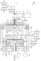
- the plasma processing apparatus PM1 shown in FIG. 2 includes a processing container 12, a stage 14, a microwave generator 16, an antenna 18, and a dielectric window 20.
- the processing container 12 defines a processing space S for performing plasma processing.
- the processing container 12 has a side wall 12a and a bottom 12b.
- the side wall 12a is formed in a substantially cylindrical shape.
- the axial line X extending in the cylindrical shape at the cylindrical center of the side wall 12a is virtually set, and the extending direction of the axial line X is referred to as the axial X direction.
- the bottom 12b is provided on the lower end side of the side wall 12a and covers the bottom opening of the side wall 12a.
- the bottom 12b is provided with an exhaust hole 12h for exhaust.
- the upper end of the side wall 12a is open.
- the upper end opening of the side wall 12 a is closed by the dielectric window 20.
- An O-ring 21 is interposed between the dielectric window 20 and the upper end portion of the side wall 12a.
- the dielectric window 20 is provided at the upper end portion of the side wall 12 a via the O-ring 21.
- the O-ring 21 makes the sealing of the processing container 12 more reliable.
- the stage 14 is accommodated in the processing space S, and the substrate W to be processed is placed thereon.
- the dielectric window 20 has a facing surface 20 a that faces the processing space S.
- the microwave generator 16 generates a microwave of 2.45 GHz, for example.
- the plasma processing apparatus PM1 further includes a tuner 22, a waveguide 24, a mode converter 26, and a coaxial waveguide 28.
- the microwave generator 16 is connected to the waveguide 24 via the tuner 22.
- the waveguide 24 is, for example, a rectangular waveguide.
- the waveguide 24 is connected to a mode converter 26, and the mode converter 26 is connected to the upper end of the coaxial waveguide 28.
- the coaxial waveguide 28 extends along the axis X.
- the coaxial waveguide 28 includes an outer conductor 28a and an inner conductor 28b.
- the outer conductor 28a has a substantially cylindrical shape extending in the axis X direction.
- the inner conductor 28b is provided inside the outer conductor 28a.
- the inner conductor 28b has a substantially cylindrical shape extending along the axis X.
- the microwave generated by the microwave generator 16 is guided to the mode converter 26 via the tuner 22 and the waveguide 24.
- the mode converter 26 converts a microwave mode and supplies the microwave after the mode conversion to the coaxial waveguide 28. Microwaves from the coaxial waveguide 28 are supplied to the antenna 18.
- the antenna 18 radiates a microwave for plasma excitation based on the microwave generated by the microwave generator 16.
- the antenna 18 includes a slot plate 30, a dielectric plate 32, and a cooling jacket 34.
- the antenna 18 is provided on a surface 20 b opposite to the facing surface 20 a of the dielectric window 20, and based on the microwave generated by the microwave generator 16, a plasma excitation micro via the dielectric window 20.
- a wave is radiated into the processing space S.
- the microwave generator 16 and the antenna 18 and the like serve as a plasma generation mechanism that supplies electromagnetic energy for converting the processing gas introduced into the processing space S into plasma.
- the slot plate 30 is formed in a substantially disc shape whose plate surface is orthogonal to the axis X.
- the slot plate 30 is disposed on the surface 20b opposite to the opposing surface 20a of the dielectric window 20 so that the plate surfaces of the dielectric window 20 and the dielectric plate 20 are aligned with each other.
- a plurality of slots 30 a are arranged in the circumferential direction about the axis X.
- FIG. 3 is a plan view of the slot plate according to the embodiment as seen from the direction of the axis X.
- the slot plate 30 is a slot plate constituting a radial line slot antenna.
- the slot plate 30 is formed in a metal disk shape having conductivity.
- a plurality of slots 30 a are formed in the slot plate 30.
- Each slot 30a includes a slot 30b and a slot 30c which are long holes extending in a direction intersecting or orthogonal to each other.
- the plurality of slots 30a are arranged at predetermined intervals in the radial direction, and are arranged at predetermined intervals in the circumferential direction.
- the plurality of slots 30a includes a first slot group 30a-1 formed by being arranged in a plurality along the circumferential direction of the slot plate 30, and the diameter of the slot plate 30 from the first slot group 30a-1. And a second slot group 30 a-2 formed in a plurality along the circumferential direction of the slot plate 30.
- a through hole 30 d through which a conduit 36 described later can pass is formed in the center portion of the slot plate 30.
- the dielectric plate 32 is formed in a substantially disc shape whose plate surface is orthogonal to the axis X.
- the dielectric plate 32 is provided between the slot plate 30 and the lower surface of the cooling jacket 34.
- the dielectric plate 32 is made of, for example, quartz and has a substantially disk shape.
- the dielectric window 20 is formed with an annular recess 20c between the disk-shaped central portion and the outer peripheral portion of the facing surface 20a facing the processing space S. As a result, the dielectric window 20 is formed with a thick portion 20d at the central portion of the disk shape and a thin portion 20e between the central portion and the outer peripheral portion of the disk shape.
- the surface of the cooling jacket 34 has conductivity.
- the cooling jacket 34 has a flow path 34a through which a refrigerant can flow, and cools the dielectric plate 32 and the slot plate 30 by the flow of the refrigerant.
- a lower end of the outer conductor 28 a is electrically connected to the upper surface of the cooling jacket 34.
- the lower end of the inner conductor 28 b is electrically connected to the slot plate 30 through a hole formed in the cooling jacket 34 and the central portion of the dielectric plate 32.
- the microwave from the coaxial waveguide 28 is propagated to the dielectric plate 32 and is introduced into the processing space S from the slot 30 a of the slot plate 30 through the dielectric window 20.
- a conduit 36 passes through the inner hole of the inner conductor 28 b of the coaxial waveguide 28.
- a through hole 30 d through which the conduit 36 can penetrate is formed at the center of the slot plate 30.
- the conduit 36 extends along the axis X and is connected to a gas supply system 38, a gas supply system 39, and a gas supply system 40.
- the gas supply system 38 supplies a processing gas for processing the substrate W to be processed to the conduit 36.
- the processing gas supplied by the gas supply system 38 includes a fluorine-based gas.
- the processing gas is an etching gas, for example, CF4 gas or CH2F2 gas.
- the gas supply system 38 may include a gas source 38a, a valve 38b, and a flow controller 38c.
- the gas source 38a is a processing gas source.
- the valve 38b switches supply and stop of supply of the processing gas from the gas source 38a.
- the flow rate controller 38c is a mass flow controller, for example, and adjusts the flow rate of the processing gas from the gas source 38a.
- the gas supply system 39 supplies a processing gas for processing the substrate to be processed W to the conduit 36.
- the processing gas supplied by the gas supply system 39 includes oxygen gas (O 2 gas).
- the gas supply system 39 may include a gas source 39a, a valve 39b, and a flow rate controller 39c.
- the gas source 39a is a gas source of oxygen gas.
- the valve 39b switches between supply and stop of gas supply from the gas source 39a.
- the flow rate controller 39c is a mass flow controller, for example, and adjusts the flow rate of the gas from the gas source 39a.
- the gas supply system 40 supplies argon gas to the conduit 36.
- argon gas is supplied from the gas supply system 40.
- the gas supply system 40 may include a gas source 40a, a valve 40b, and a flow rate controller 40c.
- the gas source 40a is a gas source of argon gas.
- the valve 40b switches supply and stop of supply of argon gas from the gas source 40a.
- the flow rate controller 40c is, for example, a mass flow controller, and adjusts the flow rate of argon gas from the gas source 40a.
- the gas supply systems 38, 39, and 40 serve as a gas supply mechanism that introduces a processing gas used for the plasma reaction into the processing space S.
- the plasma processing apparatus PM1 may further include an injector 41.
- the injector 41 supplies the gas from the conduit 36 to the through hole 20 h formed in the dielectric window 20.
- the gas supplied to the through hole 20 h of the dielectric window 20 is supplied to the processing space S.
- the gas supply path constituted by the conduit 36, the injector 41, and the through hole 20h may be referred to as a “central gas introduction unit”.
- the plasma processing apparatus PM1 further includes a gas supply unit.
- the gas supply unit 42 supplies gas from the periphery of the axis X to the processing space S between the stage 14 and the dielectric window 20.
- the gas supply unit 42 may be referred to as “peripheral gas introduction unit”.
- the gas supply unit 42 includes a conduit 42a.
- the conduit 42 a extends annularly around the axis X between the dielectric window 20 and the stage 14.
- a plurality of gas supply holes 42b are formed in the conduit 42a.
- the plurality of gas supply holes 42b are arranged in an annular shape and open toward the axis X, and supply the gas supplied to the conduit 42a toward the axis X.
- the gas supply unit 42 is connected to a gas supply system 43, a gas supply system 44, and a gas supply system 45 through a conduit 46.
- the gas supply system 43 supplies a processing gas for processing the substrate W to be processed to the gas supply unit 42.
- the processing gas supplied from the gas supply system 43 includes a fluorine-based gas, like the processing gas in the gas supply system 38. In one embodiment, this processing gas is an etching gas, for example, CF4 gas or CH2F2 gas.
- the gas supply system 43 may include a gas source 43a, a valve 43b, and a flow rate controller 43c.
- the gas source 43a is a gas source of the processing gas.
- the valve 43b switches supply and stop of supply of the processing gas from the gas source 43a.
- the flow rate controller 43c is a mass flow controller, for example, and adjusts the flow rate of the processing gas from the gas source 43a.
- the gas supply system 44 contains oxygen gas, similar to the processing gas of the gas supply system 39.
- the gas supply system 44 supplies a processing gas including oxygen gas (O 2 gas) to the gas supply unit 42.
- the gas supply system 44 may include a gas source 44a, a valve 44b, and a flow rate controller 44c.
- the gas source 44a is a gas source of oxygen gas.
- the valve 44b switches between supply and stop of gas supply from the gas source 44a.
- the flow rate controller 44c is a mass flow controller, for example, and adjusts the flow rate of the gas from the gas source 44a.
- the gas supply system 45 supplies argon gas to the gas supply unit 42.
- argon gas is supplied from the gas supply system 45.
- the gas supply system 45 may include a gas source 45a, a valve 45b, and a flow rate controller 45c.
- the gas source 45a is a gas source of argon gas.
- the valve 45b switches between supply and stop of supply of argon gas from the gas source 45a.
- the flow rate controller 45c is, for example, a mass flow controller, and adjusts the flow rate of argon gas from the gas source 45a.
- the gas supply systems 43, 44, 45 serve as a gas supply mechanism that introduces a processing gas used for the plasma reaction into the processing space S.
- the stage 14 is provided so as to face the dielectric window 20 in the axis X direction.
- the stage 14 is provided so as to sandwich the processing space S between the dielectric window 20 and the stage 14.
- a substrate W to be processed is placed on the stage 14.
- the stage 14 includes a table 14a, a focus ring 14b, and an electrostatic chuck 14c.
- the base 14 a is supported by a cylindrical support portion 48.
- the cylindrical support portion 48 is made of an insulating material and extends vertically upward from the bottom portion 12b.
- a conductive cylindrical support 50 is provided on the outer periphery of the cylindrical support 48.
- the cylindrical support portion 50 extends vertically upward from the bottom portion 12 b of the processing container 12 along the outer periphery of the cylindrical support portion 48.
- An annular exhaust passage 51 is formed between the cylindrical support portion 50 and the side wall 12a.
- An annular baffle plate 52 provided with a plurality of through holes is attached to the upper part of the exhaust passage 51.
- An exhaust device 56 is connected to the lower portion of the exhaust hole 12 h via an exhaust pipe 54.
- the exhaust device 56 has a vacuum pump such as a turbo molecular pump. The exhaust device 56 can depressurize the processing space S in the processing container 12 to a desired degree of vacuum.
- the stand 14a also serves as a high-frequency electrode.
- a high frequency power source 58 for RF bias is electrically connected to the base 14 a via a power feed rod 62 and a matching unit 60.
- the high frequency power supply 58 outputs a predetermined frequency suitable for controlling the energy of ions drawn into the substrate W to be processed, for example, a high frequency power of 13.65 MHz at a predetermined power.
- the matching unit 60 accommodates a matching unit for matching between the impedance on the high-frequency power source 58 side and the impedance on the load side such as electrodes, plasma, and the processing container 12.
- This matching unit includes a blocking capacitor for generating a self-bias.
- An electrostatic chuck 14c is provided on the upper surface of the table 14a.
- the electrostatic chuck 14c holds the substrate W to be processed with an electrostatic attraction force.
- a focus ring 14b that surrounds the periphery of the substrate W to be processed is provided on the outer side in the radial direction of the electrostatic chuck 14c.
- the electrostatic chuck 14c includes an electrode 14d, an insulating film 14e, and an insulating film 14f.
- the electrode 14d is made of a conductive film, and is provided between the insulating film 14e and the insulating film 14f.
- a high-voltage DC power supply 64 is electrically connected to the electrode 14 d via a switch 66 and a covered wire 68.
- the electrostatic chuck 14c can attract and hold the substrate W to be processed by the Coulomb force generated by the DC voltage applied from the DC power source 64.
- An annular refrigerant chamber 14g extending in the circumferential direction is provided inside the table 14a.
- a refrigerant having a predetermined temperature for example, cooling water, is circulated and supplied to the refrigerant chamber 14g from a chiller unit (not shown) via pipes 70 and 72.
- the upper surface temperature of the electrostatic chuck 14c is controlled by the temperature of the refrigerant.
- a heat transfer gas, for example, He gas is supplied between the upper surface of the electrostatic chuck 14c and the back surface of the substrate W to be processed via the gas supply pipe 74, and the substrate to be processed is determined by the upper surface temperature of the electrostatic chuck 14c.
- the temperature of W is controlled.
- the various control signals output from the control unit 10 are the microwave generator 16, the exhaust device 56, the valve 38b, the flow rate controller 38c, the valve 43b, the flow rate controller 43c, the valve 39b, the flow rate controller 39c, the valve 40b, the flow rate controller 40c, the valve 44b, the flow rate controller 44c, the valve 45b, and the flow rate controller 45c.
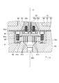
- FIG. 4 is an enlarged cross-sectional view of the injector and the through hole of the dielectric window according to the embodiment.
- the dielectric window 20 defines an accommodation space 20s and a through hole 20h in order from the top along the axis X.
- the through hole 20h allows the accommodation space 20s and the processing space S to communicate with each other.
- the through hole 20h has an area in a part between the opening on the antenna 18 side and the opening on the processing space S side, and the other part of the through hole 20h between the part and the opening on the antenna 18 side. It is comprised so that it may become smaller than the area in.
- the “area” is an area of the through hole 20 h on a plane orthogonal to the axis X.
- the through hole 20 h has a tapered shape whose diameter decreases as it goes downward along the axis X.
- the accommodating space 20s accommodates the injector 41 and one end 36b of the conduit 36.
- the conduit 36 may be made of a conductive metal.
- the conduit 36 includes a main body portion 36a and one end portion 36b.
- the main body portion 36a has a cylindrical shape extending along the axis X.
- the one end portion 36b has a substantially disc shape and has an outer diameter larger than that of the main body portion 36a.
- the conduit 36 is provided with a gas supply inner hole penetrating through the main body 36a and the one end 36b.
- the main body portion 36a of the conduit 36 passes through the inner hole of the inner conductor 28b.
- the inner conductor 28b is connected to the slot plate 30 as described above.
- the inner edge of the slot plate 30 is sandwiched between the lower end of the inner conductor 28 b and the metal member 80.
- the member 80 is fixed to the lower end of the inner conductor 28b with a screw 82.
- the upper surface of the one end portion 36 b of the conduit 36 is in contact with the lower surface of the slot plate 30.
- the injector 41 is accommodated below the one end 36b of the conduit 36 in the accommodating space 20s.
- the injector 41 has conductivity and has a substantially disk shape.
- the injector 41 is made of, for example, aluminum or stainless steel.
- the injector 41 includes a first surface 41a on the one end 36b side and a second surface 41b on the through hole 20h side.
- the injector 41 is formed with a plurality of through holes 41h extending from the first surface 41a to the second surface 41b.
- a Y2O3 film may be formed on the second surface 41b. This film may be formed by coating Y2O3 on the second surface 41b and then melting the coated film with an electron beam.
- the injector 41 is fixed to the one end portion 36b of the conduit 36 by a screw 84, and is electrically connected to the one end portion 36b. Therefore, the injector 41 can be set to the same potential as the inner conductor 28b, the slot plate 30, and the conduit 36.
- the injector 41 can be set to a ground potential, for example.
- an O-ring 86 is provided between the second surface 41 b of the injector 41 and the dielectric window 20.
- the O-ring 86 extends in an annular shape so as to surround the openings on the through hole 20h side of the plurality of through holes 41h.
- the O-ring 86 ensures airtightness between the injector 41 and the dielectric window 20.
- an O-ring 88 is provided between the first surface 41 a of the injector 41 and one end 36 b of the conduit 36.
- the O-ring 88 extends in an annular shape so as to surround the opening on the one end 36b side of the plurality of through holes 41h. Thereby, the airtightness between the injector 41 and the one end 36b of the conduit 36 is ensured.
- gas is supplied along the axis X into the processing space S from the through hole 20h of the dielectric window 20 through the through hole 41h of the conduit 36 and the injector 41. Further, gas is supplied from the gas supply unit 42 toward the axis X below the through hole 20h. Further, microwaves are introduced from the antenna 18 through the dielectric window 20 into the processing space S and / or the through hole 20 h. Thereby, plasma is generated in the processing space S and / or the through hole 20h. Thus, according to the plasma processing apparatus PM1, plasma can be generated without applying a magnetic field.
- FIG. 5 is a diagram illustrating an outline of a plasma processing method according to an embodiment.
- FIG. 5 shows a flow of the substrate W to be processed and a sequence of warm-up plasma processing and plasma processing.
- the case where the substrate W to be processed is transferred from the loading / unloading port 130 to the plasma processing apparatus PM1 and is subjected to plasma processing in the plasma processing apparatus PM1 is described as an example.
- the transfer of the substrate W to be processed will be described.
- the substrate W to be processed is installed in the carry-in / out port 130.
- the control unit 100 starts transporting the substrate W to be processed.
- the control unit 100 transports the substrate W to be processed from the loading / unloading port 130 to the alignment module 160 via the door 140 and the atmospheric transfer chamber 11.
- the alignment module 160 performs alignment processing of the substrate W to be processed.
- the control unit 100 transports the target substrate W on which the alignment process has been performed from the alignment module 160 to the load lock chamber 150 via the gate valve G1.
- the load lock chamber 150 is decompressed to a vacuum pressure after the substrate to be processed W is transferred.
- the control unit 100 transfers the substrate W to be processed from the load lock chamber 150 under vacuum pressure to the plasma processing apparatus PM1 through the gate valve G2, the vacuum transfer chamber 13, and the gate valve G3.
- the plasma processing apparatus PM1 performs a plasma process such as an etching process on the transferred substrate W to be processed.
- the control unit 100 executes a warm-up process when the transport of the substrate to be processed W is started in response to a plasma processing start command for the substrate W to be processed installed in the carry-in / out port 130.
- the processing gas is transferred to the plasma processing space S by the gas supply mechanism in a state where the processing substrate W is not installed on the stage 14 (wafer-less state) while the processing substrate W is being transported.
- electromagnetic energy is supplied by a plasma generation mechanism (warm-up plasma processing).
- the control unit 100 ends the warm-up process before the substrate to be processed W arrives at the gate valve G3 in front of the plasma processing apparatus PM1 and is transferred to the plasma processing apparatus PM1.
- the plasma processing apparatus PM1 supplies a processing gas to the plasma processing space S by a gas supply mechanism, for example, for an etching process.
- a process of supplying electromagnetic energy (plasma process) by the plasma generation mechanism is executed.
- FIG. 6 is a flowchart of a plasma processing method according to an embodiment.
- the control unit 100 executes the substrate W to be processed installed in the loading / unloading port 130. Is started (S102). Subsequently, the controller 100 starts a warm-up process when the transfer of the substrate W to be processed is started (S103). Subsequently, the control unit 100 determines whether the temperature of, for example, the central portion of the facing surface 20a of the dielectric window 20 is equal to or higher than a preset temperature, or whether a preset time has elapsed (S104). ).
- the control unit 100 performs the warm-up process until the temperature of the center portion of the dielectric window 20, for example, the central portion of the facing surface 20 a becomes equal to or higher than a preset temperature or a preset time has elapsed (No in S ⁇ b> 104). continue.
- the control unit 100 performs a warm-up process. Is finished (S105).
- the control unit 100 starts plasma processing such as plasma etching (S107).
- the warm-up process is performed while the substrate to be processed W is transported to the plasma processing apparatus PM1 in response to a command to start the plasma processing for the substrate W to be processed.
- the warm-up process is executed while the substrate to be processed W is being transported, and therefore it is difficult to affect the throughput.
- a decrease in the etching rate of the substrate W to be processed in the first lot is suppressed, and a decrease in the throughput of the plasma processing of the substrate W to be processed is suppressed. can do.
- 7A, 7B, and 7C are diagrams for explaining the effects of the plasma processing method according to the embodiment.
- 7A, 7B, and 7C are diagrams illustrating effects of the plasma processing method according to the embodiment.
- FIG. 7A is a graph showing the relationship between the temperature of the dielectric window 20 and the etching rate when the plasma etching process is performed on the substrate W to be processed without using the plasma processing method according to the embodiment. It is.
- FIGS. 7B and 7C show the relationship between the temperature of the dielectric window 20 and the etching rate when the plasma etching process is performed on the substrate W to be processed using the plasma processing method according to the embodiment. It is a graph.
- the plasma processing method according to the embodiment when the plasma processing method according to the embodiment is not used, as shown in the graph 174, when processing the target substrate W having the slot number “1”, other slots are processed.
- the temperature of the dielectric window 20 is lower than that in the case of processing the target substrate W with the number.
- the etching rate for the substrate W to be processed having the slot number “1” was lower than the etching rates of the substrates W to be processed having other slot numbers. This is called “first wafer effect”, and the slot number “1” is caused by the low temperature of the dielectric window 20 (and the processing space S) when the substrate W having the slot number “1” is processed. This is a phenomenon in which the etching rate of the substrate W to be processed becomes low.
- the warm-up process is performed while the substrate to be processed W is transported to the plasma processing apparatus PM1 in response to a command for starting the plasma processing for the substrate W to be processed. Executed.
- the dielectric window is compared with the case of processing the target substrate W having another slot number.
- the temperature of 20 was equal or slightly higher.
- the temperature of the dielectric window 20 (and the processing space S) when processing the target substrate W having the slot number “1” can be kept high.
- the etching rate for the substrate W to be processed having the slot number “1” could be kept equal to the etching rates of the substrates W to be processed having other slot numbers.
- FIG. 7C is a graph showing the relationship between the temperature of the dielectric window 20 and the etching rate when the warm-up process is performed for a longer time than in the case of FIG. 7B.
- the temperature of the dielectric window 20 when processing the target substrate W having the slot number “1”, the temperature of the dielectric window 20 is higher than when processing the target substrate W having another slot number. Became significantly higher.
- the temperature of the dielectric window 20 (and the processing space S) when processing the target substrate W having the slot number “1” can be kept high.
- the etching rate for the substrate W to be processed having the slot number “1” could be kept equal to the etching rates of the substrates W to be processed having other slot numbers.
- control unit 100 can supply a processing gas containing oxygen gas to the processing space S by the gas supply mechanism during the warm-up process.
- control unit 100 first supplies the first processing gas containing the fluorine-based gas to the processing space S by the gas supply mechanism, and then supplies the second processing gas containing the oxygen gas to the processing space. S can also be supplied. This point will be described below.
- FIG. 8 is a diagram showing the transition of the temperature of the dielectric window for each processing gas type in the plasma processing method according to the embodiment.
- the horizontal axis indicates the elapsed time (sec) from the start of the warm-up process
- the vertical axis indicates the temperature (° C.) of the dielectric window 20.
- a graph 190 shows the temperature transition of the dielectric window 20 when SF6: 150 sccm and O2: 50 sccm, which are fluorine-based gases, are supplied to the processing space S as the processing gas in the warm-up process. It is.
- the graph 191 shows the temperature transition of the dielectric window 20 when SF6: 100 sccm and O2: 100 sccm are supplied to the processing space S as processing gases in the warm-up process.
- the graph 192 shows the temperature transition of the dielectric window 20 when SF6: 50 sccm and O2: 150 sccm are supplied to the processing space S as the processing gas in the warm-up process.
- the graph 193 shows the temperature transition of the dielectric window 20 when O2: 200 sccm is supplied to the processing space S as the processing gas in the warm-up process.
- the graph 194 shows the temperature transition of the dielectric window 20 when O2: 350 sccm is supplied to the processing space S as the processing gas in the warm-up process.
- Graph 195 shows the temperature transition of the dielectric window 20 when Ar: 200 sccm is supplied to the processing space S as the processing gas in the warm-up process.
- the graph 196 shows the temperature transition of the dielectric window 20 when Ar: 150 sccm and O2: 50 sccm are supplied to the processing space S as the processing gas in the warm-up process.
- the time until the temperature of the dielectric window 20 reaches 150 (° C.) was 147 (sec) in the case of the processing gas (graph 190) of SF6: 150 sccm and O2: 50 sccm.
- the time until the temperature of the dielectric window 20 reaches 150 (° C.) was 246 (sec) in the case of the processing gas (graph 191) of SF6: 100 sccm and O2: 100 sccm.
- the time until the temperature of the dielectric window 20 reaches 150 (° C.) was 264 (sec) in the case of O 2: 200 sccm processing gas (graph 193).
- the time until the temperature of the dielectric window 20 reaches 150 (° C.) was 283 (sec) in the case of the processing gas (graph 192) of SF6: 50 sccm and O2: 150 sccm.
- the time until the temperature of the dielectric window 20 reaches 150 (° C.) was 299 (sec) in the case of a processing gas (graph 194) of O 2: 350 sccm.
- a processing gas graph 194
- Ar 200 sccm processing gas
- Ar 150 sccm
- O2 50 sccm processing gas
- the temperature of the dielectric window 20 did not reach 150 (° C.).
- a processing gas containing oxygen gas can be supplied to the processing space S as a processing gas for warm-up processing.
- the temperature rise of the dielectric window 20 due to the warm-up process becomes faster as the SF6 gas concentration is higher.
- a first processing gas containing a fluorine-based gas is supplied to the processing space S as a processing gas for warm-up processing, and then a second processing gas containing oxygen gas is supplied to the processing space S. Can be supplied. According to this, the temperature of the dielectric window 20 can be quickly raised in the warm-up process, and the inside of the processing container 12 can be cleaned before the plasma process.
- FIG. 9 is a diagram illustrating an example of a temperature measurement point of a dielectric window.
- 10 and 11 are diagrams showing an example of temperature measurement by a radiation temperature measuring device.
- the temperature measurement points of the dielectric window 20 are the point 202 on the inner surface of the thin portion 20 e provided by the recess 20 c formed in the dielectric window 20, and the center portion of the dielectric window 20.
- a point 204 on the inner surface of the thick portion 20d can be considered.
- the radiation thermometer 210 When measuring the temperature of the point 202, the radiation thermometer 210 is installed outside the side wall 12a as shown in FIG.
- the radiation thermometer 210 measures the radiant energy such as infrared rays emitted from the measurement point 202 through the measurement window 212 provided on the side wall 12a, and measures the surface temperature of the measurement point 202.
- the installation angle of the radiation thermometer 210 is adjusted as shown in FIG.
- the radiation thermometer 210 measures the radiant energy such as infrared rays emitted from the measurement point 204 through the measurement window 212 provided on the side wall 12a, and measures the surface temperature of the measurement point 204.
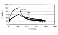
- FIG. 12 is a diagram showing a change in temperature for each temperature measurement point of the dielectric window.
- the horizontal axis indicates the elapsed time (sec) since the start of the warm-up process
- the vertical axis indicates the temperature (° C.) of the dielectric window 20.
- a graph 212 shows the temperature transition of the measurement point 202
- a graph 214 shows the temperature transition of the measurement point 204.
- the phenomenon that the etching rate of the substrate W to be processed in the initial lot such as the first lot becomes low (First wafer effect) even if the thin portion 20e reaches a predetermined temperature (for example, 150 (° C.)).
- a predetermined temperature for example, 150 (° C.)
- the thick portion 20d at the center of the dielectric window 20 has not reached a predetermined temperature (for example, 150 (° C.)).
- the thick portion 20d of the dielectric window 20 is sufficiently large. There is a risk that a first wafer effect may occur due to the fact that the substrate is not heated.
- the temperature of the thick part 20d of the dielectric window 20 is measured using the radiation thermometer 210, and the control unit 100 measures the thick part of the dielectric window 20 measured by the radiation thermometer 210. It is preferable to perform the warm-up process until the temperature of 20d becomes equal to or higher than a preset temperature (for example, 150 (° C.)).
- a preset temperature for example, 150 (° C.)
- the method for measuring the temperature of the dielectric window 20 is not limited to the radiation thermometer 210.
- an optical fiber thermometer can be used.
- FIG. 13 is a diagram illustrating an example of temperature measurement using an optical fiber thermometer.
- the optical fiber thermometer 220 is installed so as to measure the temperature of the side portion of the dielectric window 20 from the outside of the processing container 12.
- the temperature rise of the dielectric window 20 is different between the central portion and the side portion of the facing surface 20a.
- the dielectric window 20 is warmed up while measuring the temperature of the central portion. It is preferable to carry out the treatment.
- the temperature of the dielectric window 20 can be measured with a simple configuration by measuring the temperature correlation between the central portion and the side portion of the dielectric window 20 by, for example, prior experiments or simulations. For example, if the temperature at the side of the dielectric window 20 rises to a certain temperature (for example, 250 (° C.)), the temperature at the center of the facing surface 20a of the dielectric window 20 becomes the desired temperature ( For example, the temperature is such that it can be considered that the temperature has increased to 150 (° C.).
- a certain temperature for example, 250 (° C.)
- the temperature at the center of the facing surface 20a of the dielectric window 20 becomes the desired temperature (
- the temperature is such that it can be considered that the temperature has increased to 150 (° C.).
- control unit 100 determines that the temperature of the side of the dielectric window 20 measured by the optical fiber thermometer 220 is equal to the temperature of the side of the dielectric window 20 measured by the optical fiber thermometer 220 and the dielectric window 20. It is preferable to execute the warm-up process until the temperature reaches a preset temperature or higher based on the correlation with the temperature of the central portion of the opposite surface 20a.
- the configuration related to temperature measurement can be simplified.
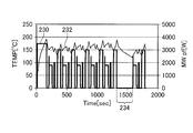
- FIG. 14A and FIG. 14B are diagrams showing the transition of the temperature of the dielectric window between lots. 14A and 14B, the horizontal axis indicates time (sec), and the vertical axis indicates the temperature (° C.) of the dielectric window 20 and the microwave power (W).
- 14A shows the transition of the temperature of the dielectric window when the time between the lots is relatively long
- FIG. 14B shows the transition of the dielectric window when the time between the lots is relatively short. It shows the transition of temperature.
- a graph 230 shows a change in the power of the microwave
- a graph 232 shows a change in the temperature of the dielectric window 20.
- a graph 240 shows a change in the power of the microwave
- a graph 242 shows a change in the temperature of the dielectric window 20.
- the temperature of the dielectric window 20 is greatly reduced.
- the average etching rate of the substrate to be processed W in the first lot (first lot) was 15.8 nm / min, whereas in the lot after the lot replacement (second lot), The average etching rate was greatly reduced to 14.6 nm / min.
- the temperature drop of the dielectric window 20 is relatively small.
- the average etching rate of the substrate to be processed W in the first lot (first lot) was 15.4 nm / min
- the lot after the lot replacement (second lot) The average etching rate was 15.3 nm / min.
- the lot-to-lot warm-up process is a state in which the substrate W is not installed on the stage 14 between the first lot and the second lot (wafer-less state), and the processing gas is supplied by the gas supply mechanism. Is supplied to the processing space S and electromagnetic energy is supplied by the plasma generation mechanism.
- FIG. 15 is a flowchart of inter-lot warm-up processing according to an embodiment. As shown in FIG. 14, when the plasma processing for the first lot is completed (S201), the control unit 100 determines whether a preset time has elapsed before performing the plasma processing for the second lot. (S202).
- control unit 100 determines that the preset time has not elapsed before the plasma processing for the second lot (S202, No). If the control unit 100 determines that the preset time has not elapsed before the plasma processing for the second lot (S202, No), the temperature of the dielectric window 20 before the plasma processing for the second lot is determined. It is determined whether or not the temperature has become lower than a preset temperature (S203).
- the control unit 100 determines that a preset time has elapsed before the execution of the plasma processing for the second lot (S202, Yes), or the temperature of the dielectric window 20 before the execution of the plasma processing for the second lot. If it is determined that the temperature has become lower than the preset temperature (S203, Yes), the inter-lot warm-up process is started (S204). Subsequently, the control unit 100 executes a plasma process for the second lot after the inter-lot warm-up process (S205).
- the lot is changed. Perform warm-up processing. Therefore, it is possible to suppress the temperature of the inner surface (dielectric window 20) of the processing container 12 from decreasing during the lot replacement time between the first lot and the second lot. It can suppress that the etching rate of the board
- the warm-up process is performed while the substrate to be processed W is transported to the plasma processing apparatus PM1 in response to a command to start the plasma processing for the substrate W to be processed. Therefore, even if the substrate to be processed W is the first lot, when performing the plasma processing on the substrate W to be processed in the first lot, for example, the temperature of the dielectric window 20 of the plasma processing apparatus PM1 is heated to a desired temperature. Has been. In addition to this, the warm-up process is executed while the substrate to be processed W is being transported, and thus it is difficult to affect the throughput.
- a decrease in the etching rate of the substrate W to be processed in the first lot is suppressed, and a decrease in the throughput of the plasma processing of the substrate W to be processed is suppressed. can do.
- the temperature of the dielectric window 20 can be quickly increased.
- the plasma processing apparatus PM1 of the present embodiment supplies a first processing gas containing a fluorine-based gas to the plasma processing space during the warm-up process, and then plasma-processes the second processing gas containing oxygen gas. Supply to space. Therefore, according to the plasma processing apparatus PM1 of the present embodiment, the temperature of the dielectric window 20 can be quickly increased by the first processing gas, and the processing container 12 can be cleaned by the second processing gas. it can.
- the plasma processing apparatus PM1 of the present embodiment when exchanging lots, when a preset time elapses or the temperature of the dielectric window 20 becomes lower than a preset temperature, Perform warm-up processing.
- the inter-lot warm-up process can suppress the temperature of the dielectric window 20 from being lowered during the lot exchange, and thus can suppress the reduction in the etching rate of the substrate W to be processed after the lot exchange. it can.
- Processing container 14 Stage 16 Microwave generator 18 Antenna 20a Opposing surface 20d Thick part 20e Thin part 20 Dielectric window 30 Slot plates 38, 39, 40, 43, 44, 45 Gas supply system 100 Control part 120 Transport mechanism 130 Loading / unloading port 150 Load lock chamber 160 Alignment module 210 Radiation thermometer 220 Optical fiber thermometer PM1 Plasma processing apparatus
Abstract
Description
14 ステージ
16 マイクロ波発生器
18 アンテナ
20a 対向面
20d 肉厚部
20e 肉薄部
20 誘電体窓
30 スロット板
38,39,40,43,44,45 ガス供給系
100 制御部
120 搬送機構
130 搬入出ポート
150 ロードロック室
160 アライメントモジュール
210 放射温度計
220 光ファイバ温度計
PM1 プラズマ処理装置
Claims (8)
- プラズマ処理空間を画成する処理容器と、
前記処理容器内に設けられ、被処理基板が設置される試料台と、
プラズマ反応に用いられる処理ガスを前記プラズマ処理空間へ導入するガス供給機構と、
前記プラズマ処理空間内に導入された処理ガスをプラズマ化するための電磁エネルギーを供給するプラズマ生成機構と、
前記処理容器の外部の基板搬入ステージに設置された被処理基板に対するプラズマ処理開始の指令が発行されて該被処理基板が前記基板搬入ステージから前記処理容器内へ搬送されている間に、前記試料台に被処理基板が設置されていない状態で、前記ガス供給機構によって前記処理ガスを前記処理空間へ供給するとともに前記プラズマ生成機構によって前記電磁エネルギーを供給するウォームアップ処理を実行する制御部と、
を備えたことを特徴とするプラズマ処理装置。 - 前記プラズマ生成機構は、
マイクロ波発生器と、
前記処理空間に対向する対向面を有する誘電体と、
前記誘電体の前記対向面の反対側の面上に設けられ、前記マイクロ波発生器によって発生されるマイクロ波に基づいて、前記誘電体を介してプラズマ励起用のマイクロ波を前記処理空間へ放射するアンテナとを有し、
前記制御部は、前記誘電体の前記対向面の中央部の温度があらかじめ設定された温度以上になるまで、前記ウォームアップ処理を実行する
ことを特徴とする請求項1に記載のプラズマ処理装置。 - 前記処理容器の外部から前記誘電体の前記対向面の中央部の温度を測定する放射温度計を備え、
前記制御部は、前記放射温度計によって測定された前記誘電体の前記対向面の中央部の温度があらかじめ設定された温度以上になるまで、前記ウォームアップ処理を実行する
ことを特徴とする請求項2に記載のプラズマ処理装置。 - 前記処理容器の外部から前記誘電体の側部の温度を測定する光ファイバ温度計を備え、
前記制御部は、前記光ファイバ温度計によって測定された前記誘電体の側部の温度が、前記光ファイバ温度計によって測定された前記誘電体の側部の温度と前記誘電体の前記対向面の中央部の温度との相関関係に基づいてあらかじめ設定された温度以上になるまで、前記ウォームアップ処理を実行する
ことを特徴とする請求項2に記載のプラズマ処理装置。 - 前記処理ガスは酸素ガスを含み、
前記制御部は、前記ガス供給機構によって前記酸素ガスを含む処理ガスを前記処理空間へ供給する
ことを特徴とする請求項1~4のいずれか1項に記載のプラズマ処理装置。 - 前記処理ガスは、フッ素系ガスを含む第1の処理ガスと、酸素ガスを含む第2の処理ガスとを含み、
前記制御部は、前記ガス供給機構によって前記第1の処理ガスを前記処理空間へ供給した後、前記ガス供給機構によって前記第2の処理ガスを前記処理空間へ供給する
ことを特徴とする請求項1~4のいずれか1項に記載のプラズマ処理装置。 - 前記制御部は、第1のロットにおいて被処理基板に対してプラズマ処理を実行した後、次ロットにおいて被処理基板に対してプラズマ処理を実行する前に、あらかじめ設定された時間が経過するか、又は前記プラズマ処理装置のあらかじめ設定された箇所の温度があらかじめ設定された温度未満になったら、前記試料台に被処理基板が設置されていない状態で前記ガス供給機構によって前記処理ガスを前記処理空間へ供給するとともに前記プラズマ生成機構によって前記電磁エネルギーを供給するロット間ウォームアップ処理を実行する
ことを特徴とする請求項1~4のいずれか1項に記載のプラズマ処理装置。 - プラズマ処理空間を画成する処理容器と、
前記処理容器内に設けられ、被処理基板が設置される試料台と、
プラズマ反応に用いられる処理ガスを前記プラズマ処理空間へ導入するガス供給機構と、
前記プラズマ処理空間内に導入された処理ガスをプラズマ化するための電磁エネルギーを供給するプラズマ生成機構と、
を備えたプラズマ処理装置を用いたプラズマ処理方法であって、
前記処理容器の外部の基板搬入ステージに設置された被処理基板に対するプラズマ処理開始の指令が発行されて該被処理基板が前記基板搬入ステージから前記処理容器内へ搬送されている間に、前記試料台に被処理基板が設置されていない状態で、前記ガス供給機構によって前記処理ガスを前記処理空間へ供給するとともに前記プラズマ生成機構によって前記電磁エネルギーを供給する
ことを特徴とするプラズマ処理方法。
Priority Applications (3)
| Application Number | Priority Date | Filing Date | Title |
|---|---|---|---|
| KR1020147029747A KR102102003B1 (ko) | 2012-05-25 | 2013-05-21 | 플라즈마 처리 장치, 및 플라즈마 처리 방법 |
| US14/396,606 US9984906B2 (en) | 2012-05-25 | 2013-05-21 | Plasma processing device and plasma processing method |
| JP2014516813A JP6014661B2 (ja) | 2012-05-25 | 2013-05-21 | プラズマ処理装置、及びプラズマ処理方法 |
Applications Claiming Priority (2)
| Application Number | Priority Date | Filing Date | Title |
|---|---|---|---|
| JP2012-119619 | 2012-05-25 | ||
| JP2012119619 | 2012-05-25 |
Publications (1)
| Publication Number | Publication Date |
|---|---|
| WO2013176144A1 true WO2013176144A1 (ja) | 2013-11-28 |
Family
ID=49623832
Family Applications (1)
| Application Number | Title | Priority Date | Filing Date |
|---|---|---|---|
| PCT/JP2013/064114 WO2013176144A1 (ja) | 2012-05-25 | 2013-05-21 | プラズマ処理装置、及びプラズマ処理方法 |
Country Status (5)
| Country | Link |
|---|---|
| US (1) | US9984906B2 (ja) |
| JP (1) | JP6014661B2 (ja) |
| KR (1) | KR102102003B1 (ja) |
| TW (1) | TWI574587B (ja) |
| WO (1) | WO2013176144A1 (ja) |
Cited By (5)
| Publication number | Priority date | Publication date | Assignee | Title |
|---|---|---|---|---|
| KR20150070036A (ko) * | 2013-12-16 | 2015-06-24 | 램 리써치 코포레이션 | 그의 온도를 결정하기 위한 광 섬유를 포함하는 플라즈마 프로세싱 장치 및 이의 컴포넌트 |
| US20160027618A1 (en) * | 2014-07-24 | 2016-01-28 | Hitachi High-Technologies Corporation | Plasma processing apparatus and plasma processing method |
| US20190103295A1 (en) * | 2017-09-29 | 2019-04-04 | Taiwan Semiconductor Manufacturing Co., Ltd. | Integrated Circuit Fabrication System with Adjustable Gas Injector |
| JP2020202243A (ja) * | 2019-06-07 | 2020-12-17 | 株式会社アルバック | プラズマ処理装置 |
| JP7480247B2 (ja) | 2017-09-20 | 2024-05-09 | 株式会社Kokusai Electric | 基板処理装置、半導体装置の製造方法及びプログラム |
Families Citing this family (241)
| Publication number | Priority date | Publication date | Assignee | Title |
|---|---|---|---|---|
| US9394608B2 (en) | 2009-04-06 | 2016-07-19 | Asm America, Inc. | Semiconductor processing reactor and components thereof |
| US8802201B2 (en) | 2009-08-14 | 2014-08-12 | Asm America, Inc. | Systems and methods for thin-film deposition of metal oxides using excited nitrogen-oxygen species |
| US20130023129A1 (en) | 2011-07-20 | 2013-01-24 | Asm America, Inc. | Pressure transmitter for a semiconductor processing environment |
| US9017481B1 (en) | 2011-10-28 | 2015-04-28 | Asm America, Inc. | Process feed management for semiconductor substrate processing |
| US10714315B2 (en) | 2012-10-12 | 2020-07-14 | Asm Ip Holdings B.V. | Semiconductor reaction chamber showerhead |
| US20160376700A1 (en) | 2013-02-01 | 2016-12-29 | Asm Ip Holding B.V. | System for treatment of deposition reactor |
| US11015245B2 (en) | 2014-03-19 | 2021-05-25 | Asm Ip Holding B.V. | Gas-phase reactor and system having exhaust plenum and components thereof |
| US10858737B2 (en) | 2014-07-28 | 2020-12-08 | Asm Ip Holding B.V. | Showerhead assembly and components thereof |
| US9890456B2 (en) | 2014-08-21 | 2018-02-13 | Asm Ip Holding B.V. | Method and system for in situ formation of gas-phase compounds |
| US10941490B2 (en) | 2014-10-07 | 2021-03-09 | Asm Ip Holding B.V. | Multiple temperature range susceptor, assembly, reactor and system including the susceptor, and methods of using the same |
| US10276355B2 (en) | 2015-03-12 | 2019-04-30 | Asm Ip Holding B.V. | Multi-zone reactor, system including the reactor, and method of using the same |
| US10458018B2 (en) | 2015-06-26 | 2019-10-29 | Asm Ip Holding B.V. | Structures including metal carbide material, devices including the structures, and methods of forming same |
| US10211308B2 (en) | 2015-10-21 | 2019-02-19 | Asm Ip Holding B.V. | NbMC layers |
| US11139308B2 (en) | 2015-12-29 | 2021-10-05 | Asm Ip Holding B.V. | Atomic layer deposition of III-V compounds to form V-NAND devices |
| US10529554B2 (en) | 2016-02-19 | 2020-01-07 | Asm Ip Holding B.V. | Method for forming silicon nitride film selectively on sidewalls or flat surfaces of trenches |
| US10190213B2 (en) | 2016-04-21 | 2019-01-29 | Asm Ip Holding B.V. | Deposition of metal borides |
| US10865475B2 (en) | 2016-04-21 | 2020-12-15 | Asm Ip Holding B.V. | Deposition of metal borides and silicides |
| US10367080B2 (en) | 2016-05-02 | 2019-07-30 | Asm Ip Holding B.V. | Method of forming a germanium oxynitride film |
| US11453943B2 (en) | 2016-05-25 | 2022-09-27 | Asm Ip Holding B.V. | Method for forming carbon-containing silicon/metal oxide or nitride film by ALD using silicon precursor and hydrocarbon precursor |
| US10184183B2 (en) * | 2016-06-21 | 2019-01-22 | Applied Materials, Inc. | Substrate temperature monitoring |
| US9859151B1 (en) | 2016-07-08 | 2018-01-02 | Asm Ip Holding B.V. | Selective film deposition method to form air gaps |
| US10612137B2 (en) | 2016-07-08 | 2020-04-07 | Asm Ip Holdings B.V. | Organic reactants for atomic layer deposition |
| KR102532607B1 (ko) | 2016-07-28 | 2023-05-15 | 에이에스엠 아이피 홀딩 비.브이. | 기판 가공 장치 및 그 동작 방법 |
| US9812320B1 (en) | 2016-07-28 | 2017-11-07 | Asm Ip Holding B.V. | Method and apparatus for filling a gap |
| US9887082B1 (en) | 2016-07-28 | 2018-02-06 | Asm Ip Holding B.V. | Method and apparatus for filling a gap |
| US10643826B2 (en) | 2016-10-26 | 2020-05-05 | Asm Ip Holdings B.V. | Methods for thermally calibrating reaction chambers |
| US11532757B2 (en) | 2016-10-27 | 2022-12-20 | Asm Ip Holding B.V. | Deposition of charge trapping layers |
| US10229833B2 (en) | 2016-11-01 | 2019-03-12 | Asm Ip Holding B.V. | Methods for forming a transition metal nitride film on a substrate by atomic layer deposition and related semiconductor device structures |
| US10714350B2 (en) | 2016-11-01 | 2020-07-14 | ASM IP Holdings, B.V. | Methods for forming a transition metal niobium nitride film on a substrate by atomic layer deposition and related semiconductor device structures |
| KR102546317B1 (ko) | 2016-11-15 | 2023-06-21 | 에이에스엠 아이피 홀딩 비.브이. | 기체 공급 유닛 및 이를 포함하는 기판 처리 장치 |
| JP2018095901A (ja) * | 2016-12-09 | 2018-06-21 | 東京エレクトロン株式会社 | 基板処理装置 |
| KR20180068582A (ko) * | 2016-12-14 | 2018-06-22 | 에이에스엠 아이피 홀딩 비.브이. | 기판 처리 장치 |
| US11581186B2 (en) | 2016-12-15 | 2023-02-14 | Asm Ip Holding B.V. | Sequential infiltration synthesis apparatus |
| US11447861B2 (en) | 2016-12-15 | 2022-09-20 | Asm Ip Holding B.V. | Sequential infiltration synthesis apparatus and a method of forming a patterned structure |
| KR20180070971A (ko) | 2016-12-19 | 2018-06-27 | 에이에스엠 아이피 홀딩 비.브이. | 기판 처리 장치 |
| US10269558B2 (en) | 2016-12-22 | 2019-04-23 | Asm Ip Holding B.V. | Method of forming a structure on a substrate |
| US10867788B2 (en) | 2016-12-28 | 2020-12-15 | Asm Ip Holding B.V. | Method of forming a structure on a substrate |
| US11390950B2 (en) | 2017-01-10 | 2022-07-19 | Asm Ip Holding B.V. | Reactor system and method to reduce residue buildup during a film deposition process |
| JP2018116836A (ja) * | 2017-01-18 | 2018-07-26 | 東京エレクトロン株式会社 | アンテナ、プラズマ処理装置及びプラズマ処理方法 |
| US10468261B2 (en) | 2017-02-15 | 2019-11-05 | Asm Ip Holding B.V. | Methods for forming a metallic film on a substrate by cyclical deposition and related semiconductor device structures |
| US10529563B2 (en) | 2017-03-29 | 2020-01-07 | Asm Ip Holdings B.V. | Method for forming doped metal oxide films on a substrate by cyclical deposition and related semiconductor device structures |
| KR102457289B1 (ko) | 2017-04-25 | 2022-10-21 | 에이에스엠 아이피 홀딩 비.브이. | 박막 증착 방법 및 반도체 장치의 제조 방법 |
| US10892156B2 (en) | 2017-05-08 | 2021-01-12 | Asm Ip Holding B.V. | Methods for forming a silicon nitride film on a substrate and related semiconductor device structures |
| US10770286B2 (en) | 2017-05-08 | 2020-09-08 | Asm Ip Holdings B.V. | Methods for selectively forming a silicon nitride film on a substrate and related semiconductor device structures |
| US10886123B2 (en) | 2017-06-02 | 2021-01-05 | Asm Ip Holding B.V. | Methods for forming low temperature semiconductor layers and related semiconductor device structures |
| US11306395B2 (en) | 2017-06-28 | 2022-04-19 | Asm Ip Holding B.V. | Methods for depositing a transition metal nitride film on a substrate by atomic layer deposition and related deposition apparatus |
| KR20190009245A (ko) | 2017-07-18 | 2019-01-28 | 에이에스엠 아이피 홀딩 비.브이. | 반도체 소자 구조물 형성 방법 및 관련된 반도체 소자 구조물 |
| US11018002B2 (en) | 2017-07-19 | 2021-05-25 | Asm Ip Holding B.V. | Method for selectively depositing a Group IV semiconductor and related semiconductor device structures |
| US10541333B2 (en) | 2017-07-19 | 2020-01-21 | Asm Ip Holding B.V. | Method for depositing a group IV semiconductor and related semiconductor device structures |
| US11374112B2 (en) | 2017-07-19 | 2022-06-28 | Asm Ip Holding B.V. | Method for depositing a group IV semiconductor and related semiconductor device structures |
| US10590535B2 (en) | 2017-07-26 | 2020-03-17 | Asm Ip Holdings B.V. | Chemical treatment, deposition and/or infiltration apparatus and method for using the same |
| US10770336B2 (en) | 2017-08-08 | 2020-09-08 | Asm Ip Holding B.V. | Substrate lift mechanism and reactor including same |
| US10692741B2 (en) | 2017-08-08 | 2020-06-23 | Asm Ip Holdings B.V. | Radiation shield |
| US11769682B2 (en) | 2017-08-09 | 2023-09-26 | Asm Ip Holding B.V. | Storage apparatus for storing cassettes for substrates and processing apparatus equipped therewith |
| US11139191B2 (en) | 2017-08-09 | 2021-10-05 | Asm Ip Holding B.V. | Storage apparatus for storing cassettes for substrates and processing apparatus equipped therewith |
| US11830730B2 (en) | 2017-08-29 | 2023-11-28 | Asm Ip Holding B.V. | Layer forming method and apparatus |
| US11295980B2 (en) | 2017-08-30 | 2022-04-05 | Asm Ip Holding B.V. | Methods for depositing a molybdenum metal film over a dielectric surface of a substrate by a cyclical deposition process and related semiconductor device structures |
| KR102491945B1 (ko) | 2017-08-30 | 2023-01-26 | 에이에스엠 아이피 홀딩 비.브이. | 기판 처리 장치 |
| US11056344B2 (en) | 2017-08-30 | 2021-07-06 | Asm Ip Holding B.V. | Layer forming method |
| KR102462379B1 (ko) * | 2017-09-20 | 2022-11-03 | 가부시키가이샤 코쿠사이 엘렉트릭 | 기판 처리 장치, 반도체 장치의 제조 방법 및 프로그램 |
| KR102630301B1 (ko) | 2017-09-21 | 2024-01-29 | 에이에스엠 아이피 홀딩 비.브이. | 침투성 재료의 순차 침투 합성 방법 처리 및 이를 이용하여 형성된 구조물 및 장치 |
| US10844484B2 (en) | 2017-09-22 | 2020-11-24 | Asm Ip Holding B.V. | Apparatus for dispensing a vapor phase reactant to a reaction chamber and related methods |
| US10658205B2 (en) | 2017-09-28 | 2020-05-19 | Asm Ip Holdings B.V. | Chemical dispensing apparatus and methods for dispensing a chemical to a reaction chamber |
| US10403504B2 (en) | 2017-10-05 | 2019-09-03 | Asm Ip Holding B.V. | Method for selectively depositing a metallic film on a substrate |
| US10923344B2 (en) | 2017-10-30 | 2021-02-16 | Asm Ip Holding B.V. | Methods for forming a semiconductor structure and related semiconductor structures |
| US10910262B2 (en) | 2017-11-16 | 2021-02-02 | Asm Ip Holding B.V. | Method of selectively depositing a capping layer structure on a semiconductor device structure |
| US11022879B2 (en) | 2017-11-24 | 2021-06-01 | Asm Ip Holding B.V. | Method of forming an enhanced unexposed photoresist layer |
| JP7206265B2 (ja) | 2017-11-27 | 2023-01-17 | エーエスエム アイピー ホールディング ビー.ブイ. | クリーン・ミニエンバイロメントを備える装置 |
| JP7214724B2 (ja) | 2017-11-27 | 2023-01-30 | エーエスエム アイピー ホールディング ビー.ブイ. | バッチ炉で利用されるウェハカセットを収納するための収納装置 |
| JP6967954B2 (ja) * | 2017-12-05 | 2021-11-17 | 東京エレクトロン株式会社 | 排気装置、処理装置及び排気方法 |
| US10872771B2 (en) | 2018-01-16 | 2020-12-22 | Asm Ip Holding B. V. | Method for depositing a material film on a substrate within a reaction chamber by a cyclical deposition process and related device structures |
| KR20200108016A (ko) | 2018-01-19 | 2020-09-16 | 에이에스엠 아이피 홀딩 비.브이. | 플라즈마 보조 증착에 의해 갭 충진 층을 증착하는 방법 |
| TW202325889A (zh) | 2018-01-19 | 2023-07-01 | 荷蘭商Asm 智慧財產控股公司 | 沈積方法 |
| US11018047B2 (en) | 2018-01-25 | 2021-05-25 | Asm Ip Holding B.V. | Hybrid lift pin |
| USD880437S1 (en) | 2018-02-01 | 2020-04-07 | Asm Ip Holding B.V. | Gas supply plate for semiconductor manufacturing apparatus |
| US11081345B2 (en) | 2018-02-06 | 2021-08-03 | Asm Ip Holding B.V. | Method of post-deposition treatment for silicon oxide film |
| EP3737779A1 (en) | 2018-02-14 | 2020-11-18 | ASM IP Holding B.V. | A method for depositing a ruthenium-containing film on a substrate by a cyclical deposition process |
| US10896820B2 (en) | 2018-02-14 | 2021-01-19 | Asm Ip Holding B.V. | Method for depositing a ruthenium-containing film on a substrate by a cyclical deposition process |
| KR102636427B1 (ko) | 2018-02-20 | 2024-02-13 | 에이에스엠 아이피 홀딩 비.브이. | 기판 처리 방법 및 장치 |
| US10975470B2 (en) | 2018-02-23 | 2021-04-13 | Asm Ip Holding B.V. | Apparatus for detecting or monitoring for a chemical precursor in a high temperature environment |
| US11473195B2 (en) | 2018-03-01 | 2022-10-18 | Asm Ip Holding B.V. | Semiconductor processing apparatus and a method for processing a substrate |
| US11629406B2 (en) | 2018-03-09 | 2023-04-18 | Asm Ip Holding B.V. | Semiconductor processing apparatus comprising one or more pyrometers for measuring a temperature of a substrate during transfer of the substrate |
| US11114283B2 (en) | 2018-03-16 | 2021-09-07 | Asm Ip Holding B.V. | Reactor, system including the reactor, and methods of manufacturing and using same |
| KR102646467B1 (ko) | 2018-03-27 | 2024-03-11 | 에이에스엠 아이피 홀딩 비.브이. | 기판 상에 전극을 형성하는 방법 및 전극을 포함하는 반도체 소자 구조 |
| US11230766B2 (en) | 2018-03-29 | 2022-01-25 | Asm Ip Holding B.V. | Substrate processing apparatus and method |
| US11088002B2 (en) | 2018-03-29 | 2021-08-10 | Asm Ip Holding B.V. | Substrate rack and a substrate processing system and method |
| KR102501472B1 (ko) | 2018-03-30 | 2023-02-20 | 에이에스엠 아이피 홀딩 비.브이. | 기판 처리 방법 |
| TW202344708A (zh) | 2018-05-08 | 2023-11-16 | 荷蘭商Asm Ip私人控股有限公司 | 藉由循環沉積製程於基板上沉積氧化物膜之方法及相關裝置結構 |
| TWI816783B (zh) | 2018-05-11 | 2023-10-01 | 荷蘭商Asm 智慧財產控股公司 | 用於基板上形成摻雜金屬碳化物薄膜之方法及相關半導體元件結構 |
| KR102596988B1 (ko) | 2018-05-28 | 2023-10-31 | 에이에스엠 아이피 홀딩 비.브이. | 기판 처리 방법 및 그에 의해 제조된 장치 |
| US11270899B2 (en) | 2018-06-04 | 2022-03-08 | Asm Ip Holding B.V. | Wafer handling chamber with moisture reduction |
| US11718913B2 (en) | 2018-06-04 | 2023-08-08 | Asm Ip Holding B.V. | Gas distribution system and reactor system including same |
| US11286562B2 (en) | 2018-06-08 | 2022-03-29 | Asm Ip Holding B.V. | Gas-phase chemical reactor and method of using same |
| KR102568797B1 (ko) | 2018-06-21 | 2023-08-21 | 에이에스엠 아이피 홀딩 비.브이. | 기판 처리 시스템 |
| US10797133B2 (en) | 2018-06-21 | 2020-10-06 | Asm Ip Holding B.V. | Method for depositing a phosphorus doped silicon arsenide film and related semiconductor device structures |
| TWI819010B (zh) | 2018-06-27 | 2023-10-21 | 荷蘭商Asm Ip私人控股有限公司 | 用於形成含金屬材料及包含含金屬材料的膜及結構之循環沉積方法 |
| US11499222B2 (en) | 2018-06-27 | 2022-11-15 | Asm Ip Holding B.V. | Cyclic deposition methods for forming metal-containing material and films and structures including the metal-containing material |
| US10612136B2 (en) | 2018-06-29 | 2020-04-07 | ASM IP Holding, B.V. | Temperature-controlled flange and reactor system including same |
| KR20200002519A (ko) | 2018-06-29 | 2020-01-08 | 에이에스엠 아이피 홀딩 비.브이. | 박막 증착 방법 및 반도체 장치의 제조 방법 |
| US10755922B2 (en) | 2018-07-03 | 2020-08-25 | Asm Ip Holding B.V. | Method for depositing silicon-free carbon-containing film as gap-fill layer by pulse plasma-assisted deposition |
| US10388513B1 (en) | 2018-07-03 | 2019-08-20 | Asm Ip Holding B.V. | Method for depositing silicon-free carbon-containing film as gap-fill layer by pulse plasma-assisted deposition |
| US10767789B2 (en) | 2018-07-16 | 2020-09-08 | Asm Ip Holding B.V. | Diaphragm valves, valve components, and methods for forming valve components |
| US11053591B2 (en) | 2018-08-06 | 2021-07-06 | Asm Ip Holding B.V. | Multi-port gas injection system and reactor system including same |
| US10883175B2 (en) | 2018-08-09 | 2021-01-05 | Asm Ip Holding B.V. | Vertical furnace for processing substrates and a liner for use therein |
| US10829852B2 (en) | 2018-08-16 | 2020-11-10 | Asm Ip Holding B.V. | Gas distribution device for a wafer processing apparatus |
| US11430674B2 (en) | 2018-08-22 | 2022-08-30 | Asm Ip Holding B.V. | Sensor array, apparatus for dispensing a vapor phase reactant to a reaction chamber and related methods |
| US11024523B2 (en) | 2018-09-11 | 2021-06-01 | Asm Ip Holding B.V. | Substrate processing apparatus and method |
| KR20200030162A (ko) | 2018-09-11 | 2020-03-20 | 에이에스엠 아이피 홀딩 비.브이. | 박막 증착 방법 |
| US11049751B2 (en) | 2018-09-14 | 2021-06-29 | Asm Ip Holding B.V. | Cassette supply system to store and handle cassettes and processing apparatus equipped therewith |
| CN110970344A (zh) | 2018-10-01 | 2020-04-07 | Asm Ip控股有限公司 | 衬底保持设备、包含所述设备的系统及其使用方法 |
| US11232963B2 (en) | 2018-10-03 | 2022-01-25 | Asm Ip Holding B.V. | Substrate processing apparatus and method |
| KR102592699B1 (ko) | 2018-10-08 | 2023-10-23 | 에이에스엠 아이피 홀딩 비.브이. | 기판 지지 유닛 및 이를 포함하는 박막 증착 장치와 기판 처리 장치 |
| KR102546322B1 (ko) | 2018-10-19 | 2023-06-21 | 에이에스엠 아이피 홀딩 비.브이. | 기판 처리 장치 및 기판 처리 방법 |
| KR102605121B1 (ko) | 2018-10-19 | 2023-11-23 | 에이에스엠 아이피 홀딩 비.브이. | 기판 처리 장치 및 기판 처리 방법 |
| USD948463S1 (en) | 2018-10-24 | 2022-04-12 | Asm Ip Holding B.V. | Susceptor for semiconductor substrate supporting apparatus |
| US11087997B2 (en) | 2018-10-31 | 2021-08-10 | Asm Ip Holding B.V. | Substrate processing apparatus for processing substrates |
| KR20200051105A (ko) | 2018-11-02 | 2020-05-13 | 에이에스엠 아이피 홀딩 비.브이. | 기판 지지 유닛 및 이를 포함하는 기판 처리 장치 |
| US11572620B2 (en) | 2018-11-06 | 2023-02-07 | Asm Ip Holding B.V. | Methods for selectively depositing an amorphous silicon film on a substrate |
| US11031242B2 (en) | 2018-11-07 | 2021-06-08 | Asm Ip Holding B.V. | Methods for depositing a boron doped silicon germanium film |
| US10818758B2 (en) | 2018-11-16 | 2020-10-27 | Asm Ip Holding B.V. | Methods for forming a metal silicate film on a substrate in a reaction chamber and related semiconductor device structures |
| US10847366B2 (en) | 2018-11-16 | 2020-11-24 | Asm Ip Holding B.V. | Methods for depositing a transition metal chalcogenide film on a substrate by a cyclical deposition process |
| US11217444B2 (en) | 2018-11-30 | 2022-01-04 | Asm Ip Holding B.V. | Method for forming an ultraviolet radiation responsive metal oxide-containing film |
| KR102636428B1 (ko) | 2018-12-04 | 2024-02-13 | 에이에스엠 아이피 홀딩 비.브이. | 기판 처리 장치를 세정하는 방법 |
| US11158513B2 (en) | 2018-12-13 | 2021-10-26 | Asm Ip Holding B.V. | Methods for forming a rhenium-containing film on a substrate by a cyclical deposition process and related semiconductor device structures |
| JP2020096183A (ja) | 2018-12-14 | 2020-06-18 | エーエスエム・アイピー・ホールディング・ベー・フェー | 窒化ガリウムの選択的堆積を用いてデバイス構造体を形成する方法及びそのためのシステム |
| TWI819180B (zh) | 2019-01-17 | 2023-10-21 | 荷蘭商Asm 智慧財產控股公司 | 藉由循環沈積製程於基板上形成含過渡金屬膜之方法 |
| KR20200091543A (ko) | 2019-01-22 | 2020-07-31 | 에이에스엠 아이피 홀딩 비.브이. | 기판 처리 장치 |
| CN111524788B (zh) | 2019-02-01 | 2023-11-24 | Asm Ip私人控股有限公司 | 氧化硅的拓扑选择性膜形成的方法 |
| KR102626263B1 (ko) | 2019-02-20 | 2024-01-16 | 에이에스엠 아이피 홀딩 비.브이. | 처리 단계를 포함하는 주기적 증착 방법 및 이를 위한 장치 |
| JP2020136678A (ja) | 2019-02-20 | 2020-08-31 | エーエスエム・アイピー・ホールディング・ベー・フェー | 基材表面内に形成された凹部を充填するための方法および装置 |
| JP2020136677A (ja) | 2019-02-20 | 2020-08-31 | エーエスエム・アイピー・ホールディング・ベー・フェー | 基材表面内に形成された凹部を充填するための周期的堆積方法および装置 |
| KR20200102357A (ko) | 2019-02-20 | 2020-08-31 | 에이에스엠 아이피 홀딩 비.브이. | 3-d nand 응용의 플러그 충진체 증착용 장치 및 방법 |
| TW202100794A (zh) | 2019-02-22 | 2021-01-01 | 荷蘭商Asm Ip私人控股有限公司 | 基材處理設備及處理基材之方法 |
| KR20200108242A (ko) | 2019-03-08 | 2020-09-17 | 에이에스엠 아이피 홀딩 비.브이. | 실리콘 질화물 층을 선택적으로 증착하는 방법, 및 선택적으로 증착된 실리콘 질화물 층을 포함하는 구조체 |
| KR20200108248A (ko) | 2019-03-08 | 2020-09-17 | 에이에스엠 아이피 홀딩 비.브이. | SiOCN 층을 포함한 구조체 및 이의 형성 방법 |
| KR20200108243A (ko) | 2019-03-08 | 2020-09-17 | 에이에스엠 아이피 홀딩 비.브이. | SiOC 층을 포함한 구조체 및 이의 형성 방법 |
| JP7183090B2 (ja) * | 2019-03-20 | 2022-12-05 | 東京エレクトロン株式会社 | プラズマ処理方法及びプラズマ処理装置 |
| KR20200116033A (ko) | 2019-03-28 | 2020-10-08 | 에이에스엠 아이피 홀딩 비.브이. | 도어 개방기 및 이를 구비한 기판 처리 장치 |
| KR20200116855A (ko) | 2019-04-01 | 2020-10-13 | 에이에스엠 아이피 홀딩 비.브이. | 반도체 소자를 제조하는 방법 |
| US11447864B2 (en) | 2019-04-19 | 2022-09-20 | Asm Ip Holding B.V. | Layer forming method and apparatus |
| KR20200125453A (ko) | 2019-04-24 | 2020-11-04 | 에이에스엠 아이피 홀딩 비.브이. | 기상 반응기 시스템 및 이를 사용하는 방법 |
| KR20200130121A (ko) | 2019-05-07 | 2020-11-18 | 에이에스엠 아이피 홀딩 비.브이. | 딥 튜브가 있는 화학물질 공급원 용기 |
| KR20200130118A (ko) | 2019-05-07 | 2020-11-18 | 에이에스엠 아이피 홀딩 비.브이. | 비정질 탄소 중합체 막을 개질하는 방법 |
| KR20200130652A (ko) | 2019-05-10 | 2020-11-19 | 에이에스엠 아이피 홀딩 비.브이. | 표면 상에 재료를 증착하는 방법 및 본 방법에 따라 형성된 구조 |
| JP2020188255A (ja) | 2019-05-16 | 2020-11-19 | エーエスエム アイピー ホールディング ビー.ブイ. | ウェハボートハンドリング装置、縦型バッチ炉および方法 |
| USD975665S1 (en) | 2019-05-17 | 2023-01-17 | Asm Ip Holding B.V. | Susceptor shaft |
| USD947913S1 (en) | 2019-05-17 | 2022-04-05 | Asm Ip Holding B.V. | Susceptor shaft |
| USD935572S1 (en) | 2019-05-24 | 2021-11-09 | Asm Ip Holding B.V. | Gas channel plate |
| USD922229S1 (en) | 2019-06-05 | 2021-06-15 | Asm Ip Holding B.V. | Device for controlling a temperature of a gas supply unit |
| KR20200141003A (ko) | 2019-06-06 | 2020-12-17 | 에이에스엠 아이피 홀딩 비.브이. | 가스 감지기를 포함하는 기상 반응기 시스템 |
| KR20200143254A (ko) | 2019-06-11 | 2020-12-23 | 에이에스엠 아이피 홀딩 비.브이. | 개질 가스를 사용하여 전자 구조를 형성하는 방법, 상기 방법을 수행하기 위한 시스템, 및 상기 방법을 사용하여 형성되는 구조 |
| USD944946S1 (en) | 2019-06-14 | 2022-03-01 | Asm Ip Holding B.V. | Shower plate |
| USD931978S1 (en) | 2019-06-27 | 2021-09-28 | Asm Ip Holding B.V. | Showerhead vacuum transport |
| KR20210005515A (ko) | 2019-07-03 | 2021-01-14 | 에이에스엠 아이피 홀딩 비.브이. | 기판 처리 장치용 온도 제어 조립체 및 이를 사용하는 방법 |
| JP2021015791A (ja) | 2019-07-09 | 2021-02-12 | エーエスエム アイピー ホールディング ビー.ブイ. | 同軸導波管を用いたプラズマ装置、基板処理方法 |
| CN112216646A (zh) | 2019-07-10 | 2021-01-12 | Asm Ip私人控股有限公司 | 基板支撑组件及包括其的基板处理装置 |
| KR20210010307A (ko) | 2019-07-16 | 2021-01-27 | 에이에스엠 아이피 홀딩 비.브이. | 기판 처리 장치 |
| KR20210010820A (ko) | 2019-07-17 | 2021-01-28 | 에이에스엠 아이피 홀딩 비.브이. | 실리콘 게르마늄 구조를 형성하는 방법 |
| KR20210010816A (ko) | 2019-07-17 | 2021-01-28 | 에이에스엠 아이피 홀딩 비.브이. | 라디칼 보조 점화 플라즈마 시스템 및 방법 |
| US11643724B2 (en) | 2019-07-18 | 2023-05-09 | Asm Ip Holding B.V. | Method of forming structures using a neutral beam |
| JP2021019198A (ja) | 2019-07-19 | 2021-02-15 | エーエスエム・アイピー・ホールディング・ベー・フェー | トポロジー制御されたアモルファスカーボンポリマー膜の形成方法 |
| CN112309843A (zh) | 2019-07-29 | 2021-02-02 | Asm Ip私人控股有限公司 | 实现高掺杂剂掺入的选择性沉积方法 |
| CN112309899A (zh) | 2019-07-30 | 2021-02-02 | Asm Ip私人控股有限公司 | 基板处理设备 |
| CN112309900A (zh) | 2019-07-30 | 2021-02-02 | Asm Ip私人控股有限公司 | 基板处理设备 |
| US11587815B2 (en) | 2019-07-31 | 2023-02-21 | Asm Ip Holding B.V. | Vertical batch furnace assembly |
| US11587814B2 (en) | 2019-07-31 | 2023-02-21 | Asm Ip Holding B.V. | Vertical batch furnace assembly |
| US11227782B2 (en) | 2019-07-31 | 2022-01-18 | Asm Ip Holding B.V. | Vertical batch furnace assembly |
| KR20210018759A (ko) | 2019-08-05 | 2021-02-18 | 에이에스엠 아이피 홀딩 비.브이. | 화학물질 공급원 용기를 위한 액체 레벨 센서 |
| USD965524S1 (en) | 2019-08-19 | 2022-10-04 | Asm Ip Holding B.V. | Susceptor support |
| USD965044S1 (en) | 2019-08-19 | 2022-09-27 | Asm Ip Holding B.V. | Susceptor shaft |
| JP2021031769A (ja) | 2019-08-21 | 2021-03-01 | エーエスエム アイピー ホールディング ビー.ブイ. | 成膜原料混合ガス生成装置及び成膜装置 |
| USD940837S1 (en) | 2019-08-22 | 2022-01-11 | Asm Ip Holding B.V. | Electrode |
| USD949319S1 (en) | 2019-08-22 | 2022-04-19 | Asm Ip Holding B.V. | Exhaust duct |
| USD979506S1 (en) | 2019-08-22 | 2023-02-28 | Asm Ip Holding B.V. | Insulator |
| USD930782S1 (en) | 2019-08-22 | 2021-09-14 | Asm Ip Holding B.V. | Gas distributor |
| KR20210024423A (ko) | 2019-08-22 | 2021-03-05 | 에이에스엠 아이피 홀딩 비.브이. | 홀을 구비한 구조체를 형성하기 위한 방법 |
| US11286558B2 (en) | 2019-08-23 | 2022-03-29 | Asm Ip Holding B.V. | Methods for depositing a molybdenum nitride film on a surface of a substrate by a cyclical deposition process and related semiconductor device structures including a molybdenum nitride film |
| KR20210024420A (ko) | 2019-08-23 | 2021-03-05 | 에이에스엠 아이피 홀딩 비.브이. | 비스(디에틸아미노)실란을 사용하여 peald에 의해 개선된 품질을 갖는 실리콘 산화물 막을 증착하기 위한 방법 |
| KR20210029090A (ko) | 2019-09-04 | 2021-03-15 | 에이에스엠 아이피 홀딩 비.브이. | 희생 캡핑 층을 이용한 선택적 증착 방법 |
| KR20210029663A (ko) | 2019-09-05 | 2021-03-16 | 에이에스엠 아이피 홀딩 비.브이. | 기판 처리 장치 |
| US11562901B2 (en) | 2019-09-25 | 2023-01-24 | Asm Ip Holding B.V. | Substrate processing method |
| CN112593212B (zh) | 2019-10-02 | 2023-12-22 | Asm Ip私人控股有限公司 | 通过循环等离子体增强沉积工艺形成拓扑选择性氧化硅膜的方法 |
| TW202129060A (zh) | 2019-10-08 | 2021-08-01 | 荷蘭商Asm Ip控股公司 | 基板處理裝置、及基板處理方法 |
| KR20210043460A (ko) | 2019-10-10 | 2021-04-21 | 에이에스엠 아이피 홀딩 비.브이. | 포토레지스트 하부층을 형성하기 위한 방법 및 이를 포함한 구조체 |
| KR20210045930A (ko) | 2019-10-16 | 2021-04-27 | 에이에스엠 아이피 홀딩 비.브이. | 실리콘 산화물의 토폴로지-선택적 막의 형성 방법 |
| US11637014B2 (en) | 2019-10-17 | 2023-04-25 | Asm Ip Holding B.V. | Methods for selective deposition of doped semiconductor material |
| KR20210047808A (ko) | 2019-10-21 | 2021-04-30 | 에이에스엠 아이피 홀딩 비.브이. | 막을 선택적으로 에칭하기 위한 장치 및 방법 |
| US11646205B2 (en) | 2019-10-29 | 2023-05-09 | Asm Ip Holding B.V. | Methods of selectively forming n-type doped material on a surface, systems for selectively forming n-type doped material, and structures formed using same |
| KR20210054983A (ko) | 2019-11-05 | 2021-05-14 | 에이에스엠 아이피 홀딩 비.브이. | 도핑된 반도체 층을 갖는 구조체 및 이를 형성하기 위한 방법 및 시스템 |
| US11501968B2 (en) | 2019-11-15 | 2022-11-15 | Asm Ip Holding B.V. | Method for providing a semiconductor device with silicon filled gaps |
| KR20210062561A (ko) | 2019-11-20 | 2021-05-31 | 에이에스엠 아이피 홀딩 비.브이. | 기판의 표면 상에 탄소 함유 물질을 증착하는 방법, 상기 방법을 사용하여 형성된 구조물, 및 상기 구조물을 형성하기 위한 시스템 |
| KR20210065848A (ko) | 2019-11-26 | 2021-06-04 | 에이에스엠 아이피 홀딩 비.브이. | 제1 유전체 표면과 제2 금속성 표면을 포함한 기판 상에 타겟 막을 선택적으로 형성하기 위한 방법 |
| CN112951697A (zh) | 2019-11-26 | 2021-06-11 | Asm Ip私人控股有限公司 | 基板处理设备 |
| CN112885692A (zh) | 2019-11-29 | 2021-06-01 | Asm Ip私人控股有限公司 | 基板处理设备 |
| CN112885693A (zh) | 2019-11-29 | 2021-06-01 | Asm Ip私人控股有限公司 | 基板处理设备 |
| JP2021090042A (ja) | 2019-12-02 | 2021-06-10 | エーエスエム アイピー ホールディング ビー.ブイ. | 基板処理装置、基板処理方法 |
| KR20210070898A (ko) | 2019-12-04 | 2021-06-15 | 에이에스엠 아이피 홀딩 비.브이. | 기판 처리 장치 |
| CN112992667A (zh) | 2019-12-17 | 2021-06-18 | Asm Ip私人控股有限公司 | 形成氮化钒层的方法和包括氮化钒层的结构 |
| US11527403B2 (en) | 2019-12-19 | 2022-12-13 | Asm Ip Holding B.V. | Methods for filling a gap feature on a substrate surface and related semiconductor structures |
| KR20210095050A (ko) | 2020-01-20 | 2021-07-30 | 에이에스엠 아이피 홀딩 비.브이. | 박막 형성 방법 및 박막 표면 개질 방법 |
| TW202130846A (zh) | 2020-02-03 | 2021-08-16 | 荷蘭商Asm Ip私人控股有限公司 | 形成包括釩或銦層的結構之方法 |
| KR102614972B1 (ko) * | 2020-02-03 | 2023-12-19 | 주식회사 히타치하이테크 | 플라스마 처리 장치 및 플라스마 처리 방법 |
| KR20210100010A (ko) | 2020-02-04 | 2021-08-13 | 에이에스엠 아이피 홀딩 비.브이. | 대형 물품의 투과율 측정을 위한 방법 및 장치 |
| US11776846B2 (en) | 2020-02-07 | 2023-10-03 | Asm Ip Holding B.V. | Methods for depositing gap filling fluids and related systems and devices |
| US11781243B2 (en) | 2020-02-17 | 2023-10-10 | Asm Ip Holding B.V. | Method for depositing low temperature phosphorous-doped silicon |
| KR20210116240A (ko) | 2020-03-11 | 2021-09-27 | 에이에스엠 아이피 홀딩 비.브이. | 조절성 접합부를 갖는 기판 핸들링 장치 |
| US11876356B2 (en) | 2020-03-11 | 2024-01-16 | Asm Ip Holding B.V. | Lockout tagout assembly and system and method of using same |
| CN113394086A (zh) | 2020-03-12 | 2021-09-14 | Asm Ip私人控股有限公司 | 用于制造具有目标拓扑轮廓的层结构的方法 |
| KR20210124042A (ko) | 2020-04-02 | 2021-10-14 | 에이에스엠 아이피 홀딩 비.브이. | 박막 형성 방법 |
| TW202146689A (zh) | 2020-04-03 | 2021-12-16 | 荷蘭商Asm Ip控股公司 | 阻障層形成方法及半導體裝置的製造方法 |
| TW202145344A (zh) | 2020-04-08 | 2021-12-01 | 荷蘭商Asm Ip私人控股有限公司 | 用於選擇性蝕刻氧化矽膜之設備及方法 |
| US11821078B2 (en) | 2020-04-15 | 2023-11-21 | Asm Ip Holding B.V. | Method for forming precoat film and method for forming silicon-containing film |
| US11898243B2 (en) | 2020-04-24 | 2024-02-13 | Asm Ip Holding B.V. | Method of forming vanadium nitride-containing layer |
| KR20210132605A (ko) | 2020-04-24 | 2021-11-04 | 에이에스엠 아이피 홀딩 비.브이. | 냉각 가스 공급부를 포함한 수직형 배치 퍼니스 어셈블리 |
| KR20210132600A (ko) | 2020-04-24 | 2021-11-04 | 에이에스엠 아이피 홀딩 비.브이. | 바나듐, 질소 및 추가 원소를 포함한 층을 증착하기 위한 방법 및 시스템 |
| KR20210134226A (ko) | 2020-04-29 | 2021-11-09 | 에이에스엠 아이피 홀딩 비.브이. | 고체 소스 전구체 용기 |
| KR20210134869A (ko) | 2020-05-01 | 2021-11-11 | 에이에스엠 아이피 홀딩 비.브이. | Foup 핸들러를 이용한 foup의 빠른 교환 |
| KR20210141379A (ko) | 2020-05-13 | 2021-11-23 | 에이에스엠 아이피 홀딩 비.브이. | 반응기 시스템용 레이저 정렬 고정구 |
| KR20210143653A (ko) | 2020-05-19 | 2021-11-29 | 에이에스엠 아이피 홀딩 비.브이. | 기판 처리 장치 |
| KR20210145078A (ko) | 2020-05-21 | 2021-12-01 | 에이에스엠 아이피 홀딩 비.브이. | 다수의 탄소 층을 포함한 구조체 및 이를 형성하고 사용하는 방법 |
| TW202201602A (zh) | 2020-05-29 | 2022-01-01 | 荷蘭商Asm Ip私人控股有限公司 | 基板處理方法 |
| TW202218133A (zh) | 2020-06-24 | 2022-05-01 | 荷蘭商Asm Ip私人控股有限公司 | 形成含矽層之方法 |
| TW202217953A (zh) | 2020-06-30 | 2022-05-01 | 荷蘭商Asm Ip私人控股有限公司 | 基板處理方法 |
| KR20220010438A (ko) | 2020-07-17 | 2022-01-25 | 에이에스엠 아이피 홀딩 비.브이. | 포토리소그래피에 사용하기 위한 구조체 및 방법 |
| TW202204662A (zh) | 2020-07-20 | 2022-02-01 | 荷蘭商Asm Ip私人控股有限公司 | 用於沉積鉬層之方法及系統 |
| TW202212623A (zh) | 2020-08-26 | 2022-04-01 | 荷蘭商Asm Ip私人控股有限公司 | 形成金屬氧化矽層及金屬氮氧化矽層的方法、半導體結構、及系統 |
| USD990534S1 (en) | 2020-09-11 | 2023-06-27 | Asm Ip Holding B.V. | Weighted lift pin |
| USD1012873S1 (en) | 2020-09-24 | 2024-01-30 | Asm Ip Holding B.V. | Electrode for semiconductor processing apparatus |
| TW202229613A (zh) | 2020-10-14 | 2022-08-01 | 荷蘭商Asm Ip私人控股有限公司 | 於階梯式結構上沉積材料的方法 |
| TW202217037A (zh) | 2020-10-22 | 2022-05-01 | 荷蘭商Asm Ip私人控股有限公司 | 沉積釩金屬的方法、結構、裝置及沉積總成 |
| TW202223136A (zh) | 2020-10-28 | 2022-06-16 | 荷蘭商Asm Ip私人控股有限公司 | 用於在基板上形成層之方法、及半導體處理系統 |
| KR20220076343A (ko) | 2020-11-30 | 2022-06-08 | 에이에스엠 아이피 홀딩 비.브이. | 기판 처리 장치의 반응 챔버 내에 배열되도록 구성된 인젝터 |
| CN114639631A (zh) | 2020-12-16 | 2022-06-17 | Asm Ip私人控股有限公司 | 跳动和摆动测量固定装置 |
| TW202231903A (zh) | 2020-12-22 | 2022-08-16 | 荷蘭商Asm Ip私人控股有限公司 | 過渡金屬沉積方法、過渡金屬層、用於沉積過渡金屬於基板上的沉積總成 |
| USD980814S1 (en) | 2021-05-11 | 2023-03-14 | Asm Ip Holding B.V. | Gas distributor for substrate processing apparatus |
| USD1023959S1 (en) | 2021-05-11 | 2024-04-23 | Asm Ip Holding B.V. | Electrode for substrate processing apparatus |
| USD980813S1 (en) | 2021-05-11 | 2023-03-14 | Asm Ip Holding B.V. | Gas flow control plate for substrate processing apparatus |
| USD981973S1 (en) | 2021-05-11 | 2023-03-28 | Asm Ip Holding B.V. | Reactor wall for substrate processing apparatus |
| USD990441S1 (en) | 2021-09-07 | 2023-06-27 | Asm Ip Holding B.V. | Gas flow control plate |
| US20230163001A1 (en) * | 2021-11-23 | 2023-05-25 | Applied Materials, Inc. | Method to eliminate first wafer effects on semiconductor process chambers |
| KR102619965B1 (ko) * | 2022-05-16 | 2024-01-02 | 세메스 주식회사 | 기판 처리 장치 및 기판 처리 방법 |
Citations (1)
| Publication number | Priority date | Publication date | Assignee | Title |
|---|---|---|---|---|
| JPH09172003A (ja) * | 1995-09-05 | 1997-06-30 | Applied Materials Inc | プラズマ処理における温度制御の方法及び装置 |
Family Cites Families (22)
| Publication number | Priority date | Publication date | Assignee | Title |
|---|---|---|---|---|
| US3664942A (en) * | 1970-12-31 | 1972-05-23 | Ibm | End point detection method and apparatus for sputter etching |
| US6024826A (en) * | 1996-05-13 | 2000-02-15 | Applied Materials, Inc. | Plasma reactor with heated source of a polymer-hardening precursor material |
| JP2943691B2 (ja) * | 1996-04-25 | 1999-08-30 | 日本電気株式会社 | プラズマ処理装置 |
| US6030666A (en) * | 1997-03-31 | 2000-02-29 | Lam Research Corporation | Method for microwave plasma substrate heating |
| JP4053173B2 (ja) * | 1999-03-29 | 2008-02-27 | 東京エレクトロン株式会社 | マイクロ波プラズマ処理装置及び方法 |
| US20020100557A1 (en) * | 2001-01-29 | 2002-08-01 | Applied Materials, Inc. | ICP window heater integrated with faraday shield or floating electrode between the source power coil and the ICP window |
| WO2003088342A1 (fr) * | 2002-03-29 | 2003-10-23 | Tokyo Electron Limited | Procede de fabrication de materiau d'un dispositif electronique |
| US7569497B2 (en) * | 2002-07-30 | 2009-08-04 | Tokyo Electron Limited | Method and apparatus for forming insulating layer |
| JP4136630B2 (ja) * | 2002-12-03 | 2008-08-20 | キヤノン株式会社 | プラズマ処理装置 |
| JP4563729B2 (ja) * | 2003-09-04 | 2010-10-13 | 東京エレクトロン株式会社 | プラズマ処理装置 |
| JP4361811B2 (ja) * | 2004-01-09 | 2009-11-11 | 東京エレクトロン株式会社 | 半導体製造装置 |
| JP4490704B2 (ja) | 2004-02-27 | 2010-06-30 | 株式会社日立ハイテクノロジーズ | プラズマ処理方法 |
| US9157151B2 (en) | 2006-06-05 | 2015-10-13 | Applied Materials, Inc. | Elimination of first wafer effect for PECVD films |
| JP4646941B2 (ja) * | 2007-03-30 | 2011-03-09 | 東京エレクトロン株式会社 | 基板処理装置及びその処理室内の状態安定化方法 |
| JP5545795B2 (ja) * | 2008-02-26 | 2014-07-09 | 株式会社日立国際電気 | 基板処理装置及び半導体製造装置管理方法 |
| WO2010001938A1 (ja) * | 2008-07-04 | 2010-01-07 | 東京エレクトロン株式会社 | プラズマ処理装置、プラズマ処理方法および誘電体窓の温度調節機構 |
| JP2010016225A (ja) * | 2008-07-04 | 2010-01-21 | Tokyo Electron Ltd | 温度調節機構および温度調節機構を用いた半導体製造装置 |
| JP2010153508A (ja) * | 2008-12-24 | 2010-07-08 | Hitachi High-Technologies Corp | 試料のエッチング処理方法 |
| JP2010219198A (ja) | 2009-03-16 | 2010-09-30 | Hitachi High-Technologies Corp | プラズマ処理装置 |
| JP5457109B2 (ja) * | 2009-09-02 | 2014-04-02 | 東京エレクトロン株式会社 | プラズマ処理装置 |
| US8608852B2 (en) * | 2010-06-11 | 2013-12-17 | Applied Materials, Inc. | Temperature controlled plasma processing chamber component with zone dependent thermal efficiencies |
| TWI473163B (zh) * | 2010-09-15 | 2015-02-11 | Tokyo Electron Ltd | A plasma etching processing apparatus, a plasma etching processing method, and a semiconductor device manufacturing method |
-
2013
- 2013-05-21 JP JP2014516813A patent/JP6014661B2/ja not_active Expired - Fee Related
- 2013-05-21 US US14/396,606 patent/US9984906B2/en active Active
- 2013-05-21 WO PCT/JP2013/064114 patent/WO2013176144A1/ja active Application Filing
- 2013-05-21 KR KR1020147029747A patent/KR102102003B1/ko active IP Right Grant
- 2013-05-24 TW TW102118456A patent/TWI574587B/zh not_active IP Right Cessation
Patent Citations (1)
| Publication number | Priority date | Publication date | Assignee | Title |
|---|---|---|---|---|
| JPH09172003A (ja) * | 1995-09-05 | 1997-06-30 | Applied Materials Inc | プラズマ処理における温度制御の方法及び装置 |
Cited By (8)
| Publication number | Priority date | Publication date | Assignee | Title |
|---|---|---|---|---|
| KR20150070036A (ko) * | 2013-12-16 | 2015-06-24 | 램 리써치 코포레이션 | 그의 온도를 결정하기 위한 광 섬유를 포함하는 플라즈마 프로세싱 장치 및 이의 컴포넌트 |
| KR102378049B1 (ko) | 2013-12-16 | 2022-03-23 | 램 리써치 코포레이션 | 플라즈마 프로세싱 장치 및 이의 온도를 결정하기 위한 광 섬유를 포함하는 이의 컴포넌트 |
| US20160027618A1 (en) * | 2014-07-24 | 2016-01-28 | Hitachi High-Technologies Corporation | Plasma processing apparatus and plasma processing method |
| JP7480247B2 (ja) | 2017-09-20 | 2024-05-09 | 株式会社Kokusai Electric | 基板処理装置、半導体装置の製造方法及びプログラム |
| US20190103295A1 (en) * | 2017-09-29 | 2019-04-04 | Taiwan Semiconductor Manufacturing Co., Ltd. | Integrated Circuit Fabrication System with Adjustable Gas Injector |
| US11670490B2 (en) * | 2017-09-29 | 2023-06-06 | Taiwan Semiconductor Manufacturing Co., Ltd. | Integrated circuit fabrication system with adjustable gas injector |
| JP2020202243A (ja) * | 2019-06-07 | 2020-12-17 | 株式会社アルバック | プラズマ処理装置 |
| JP7267843B2 (ja) | 2019-06-07 | 2023-05-02 | 株式会社アルバック | プラズマ処理装置 |
Also Published As
| Publication number | Publication date |
|---|---|
| US20150064923A1 (en) | 2015-03-05 |
| TW201410081A (zh) | 2014-03-01 |
| TWI574587B (zh) | 2017-03-11 |
| JPWO2013176144A1 (ja) | 2016-01-14 |
| JP6014661B2 (ja) | 2016-10-25 |
| KR102102003B1 (ko) | 2020-04-20 |
| KR20150016491A (ko) | 2015-02-12 |
| US9984906B2 (en) | 2018-05-29 |
Similar Documents
| Publication | Publication Date | Title |
|---|---|---|
| JP6014661B2 (ja) | プラズマ処理装置、及びプラズマ処理方法 | |
| US11328904B2 (en) | Substrate processing apparatus | |
| US9252001B2 (en) | Plasma processing apparatus, plasma processing method and storage medium | |
| TWI802347B (zh) | 用於電漿處理中之均勻性控制的漸縮上電極 | |
| CN109509694B (zh) | 等离子体处理装置和等离子体处理方法 | |
| KR102487930B1 (ko) | 기판 지지 장치 및 이를 포함하는 플라즈마 처리 장치 | |
| KR20140114817A (ko) | 플라즈마 처리 장치 및 히터의 온도 제어 방법 | |
| US11195696B2 (en) | Electron beam generator, plasma processing apparatus having the same and plasma processing method using the same | |
| KR20180054495A (ko) | 이중 주파수 표면파 플라즈마 소스 | |
| US20190355598A1 (en) | Processing apparatus, member, and temperature control method | |
| KR20200051505A (ko) | 배치대 및 기판 처리 장치 | |
| JP7246451B2 (ja) | プラズマ処理装置及びプラズマ処理方法 | |
| CN115497801A (zh) | 基板处理装置及基板处理方法 | |
| CN115398603A (zh) | 等离子处理装置以及等离子处理方法 | |
| JPWO2006118215A1 (ja) | 基板処理装置および半導体デバイスの製造方法 | |
| US10593522B2 (en) | Electrostatic chuck, placing table and plasma processing apparatus | |
| US20240079208A1 (en) | Plasma processing apparatus | |
| US20220037124A1 (en) | Plasma processing apparatus and plasma processing method | |
| TW202205348A (zh) | 邊緣環及電漿處理裝置 |
Legal Events
| Date | Code | Title | Description |
|---|---|---|---|
| 121 | Ep: the epo has been informed by wipo that ep was designated in this application |
Ref document number: 13793245 Country of ref document: EP Kind code of ref document: A1 |
|
| ENP | Entry into the national phase |
Ref document number: 2014516813 Country of ref document: JP Kind code of ref document: A |
|
| ENP | Entry into the national phase |
Ref document number: 20147029747 Country of ref document: KR Kind code of ref document: A |
|
| WWE | Wipo information: entry into national phase |
Ref document number: 14396606 Country of ref document: US |
|
| NENP | Non-entry into the national phase |
Ref country code: DE |
|
| 122 | Ep: pct application non-entry in european phase |
Ref document number: 13793245 Country of ref document: EP Kind code of ref document: A1 |