WO2013129143A1 - 荷電粒子線装置 - Google Patents
荷電粒子線装置 Download PDFInfo
- Publication number
- WO2013129143A1 WO2013129143A1 PCT/JP2013/053737 JP2013053737W WO2013129143A1 WO 2013129143 A1 WO2013129143 A1 WO 2013129143A1 JP 2013053737 W JP2013053737 W JP 2013053737W WO 2013129143 A1 WO2013129143 A1 WO 2013129143A1
- Authority
- WO
- WIPO (PCT)
- Prior art keywords
- charged particle
- diaphragm
- housing
- particle beam
- space
- Prior art date
- Legal status (The legal status is an assumption and is not a legal conclusion. Google has not performed a legal analysis and makes no representation as to the accuracy of the status listed.)
- Ceased
Links
Images

Classifications
-
- H—ELECTRICITY
- H01—ELECTRIC ELEMENTS
- H01J—ELECTRIC DISCHARGE TUBES OR DISCHARGE LAMPS
- H01J37/00—Discharge tubes with provision for introducing objects or material to be exposed to the discharge, e.g. for the purpose of examination or processing thereof
- H01J37/26—Electron or ion microscopes; Electron or ion diffraction tubes
- H01J37/28—Electron or ion microscopes; Electron or ion diffraction tubes with scanning beams
-
- H—ELECTRICITY
- H01—ELECTRIC ELEMENTS
- H01J—ELECTRIC DISCHARGE TUBES OR DISCHARGE LAMPS
- H01J37/00—Discharge tubes with provision for introducing objects or material to be exposed to the discharge, e.g. for the purpose of examination or processing thereof
- H01J37/02—Details
- H01J37/04—Arrangements of electrodes and associated parts for generating or controlling the discharge, e.g. electron-optical arrangement or ion-optical arrangement
- H01J37/09—Diaphragms; Shields associated with electron or ion-optical arrangements; Compensation of disturbing fields
-
- H—ELECTRICITY
- H01—ELECTRIC ELEMENTS
- H01J—ELECTRIC DISCHARGE TUBES OR DISCHARGE LAMPS
- H01J37/00—Discharge tubes with provision for introducing objects or material to be exposed to the discharge, e.g. for the purpose of examination or processing thereof
- H01J37/02—Details
- H01J37/16—Vessels; Containers
-
- H—ELECTRICITY
- H01—ELECTRIC ELEMENTS
- H01J—ELECTRIC DISCHARGE TUBES OR DISCHARGE LAMPS
- H01J37/00—Discharge tubes with provision for introducing objects or material to be exposed to the discharge, e.g. for the purpose of examination or processing thereof
- H01J37/02—Details
- H01J37/18—Vacuum locks ; Means for obtaining or maintaining the desired pressure within the vessel
-
- H—ELECTRICITY
- H01—ELECTRIC ELEMENTS
- H01J—ELECTRIC DISCHARGE TUBES OR DISCHARGE LAMPS
- H01J2237/00—Discharge tubes exposing object to beam, e.g. for analysis treatment, etching, imaging
- H01J2237/04—Means for controlling the discharge
- H01J2237/045—Diaphragms
- H01J2237/0451—Diaphragms with fixed aperture
-
- H—ELECTRICITY
- H01—ELECTRIC ELEMENTS
- H01J—ELECTRIC DISCHARGE TUBES OR DISCHARGE LAMPS
- H01J2237/00—Discharge tubes exposing object to beam, e.g. for analysis treatment, etching, imaging
- H01J2237/06—Sources
- H01J2237/063—Electron sources
- H01J2237/06325—Cold-cathode sources
- H01J2237/06341—Field emission
-
- H—ELECTRICITY
- H01—ELECTRIC ELEMENTS
- H01J—ELECTRIC DISCHARGE TUBES OR DISCHARGE LAMPS
- H01J2237/00—Discharge tubes exposing object to beam, e.g. for analysis treatment, etching, imaging
- H01J2237/10—Lenses
-
- H—ELECTRICITY
- H01—ELECTRIC ELEMENTS
- H01J—ELECTRIC DISCHARGE TUBES OR DISCHARGE LAMPS
- H01J2237/00—Discharge tubes exposing object to beam, e.g. for analysis treatment, etching, imaging
- H01J2237/10—Lenses
- H01J2237/14—Lenses magnetic
- H01J2237/1405—Constructional details
-
- H—ELECTRICITY
- H01—ELECTRIC ELEMENTS
- H01J—ELECTRIC DISCHARGE TUBES OR DISCHARGE LAMPS
- H01J2237/00—Discharge tubes exposing object to beam, e.g. for analysis treatment, etching, imaging
- H01J2237/16—Vessels
- H01J2237/164—Particle-permeable windows
-
- H—ELECTRICITY
- H01—ELECTRIC ELEMENTS
- H01J—ELECTRIC DISCHARGE TUBES OR DISCHARGE LAMPS
- H01J2237/00—Discharge tubes exposing object to beam, e.g. for analysis treatment, etching, imaging
- H01J2237/26—Electron or ion microscopes
- H01J2237/2602—Details
- H01J2237/2605—Details operating at elevated pressures, e.g. atmosphere
- H01J2237/2608—Details operating at elevated pressures, e.g. atmosphere with environmental specimen chamber
-
- H—ELECTRICITY
- H01—ELECTRIC ELEMENTS
- H01J—ELECTRIC DISCHARGE TUBES OR DISCHARGE LAMPS
- H01J2237/00—Discharge tubes exposing object to beam, e.g. for analysis treatment, etching, imaging
- H01J2237/26—Electron or ion microscopes
- H01J2237/28—Scanning microscopes
- H01J2237/2801—Details
Definitions
- the present invention relates to a charged particle beam apparatus for irradiating a sample with charged particle beams.
- charged particle beam devices such as scanning electron microscope (SEM), transmission electron microscope (TEM), scanning transmission electron microscope (STEM), and focused ion beam processing and observation apparatus (FIB) have been used to observe minute regions. ing.
- SEM scanning electron microscope
- TEM transmission electron microscope
- STEM scanning transmission electron microscope
- FIB focused ion beam processing and observation apparatus
- a charged particle beam such as an electron beam or ion beam is irradiated to a sample.
- imaging is performed by evacuating a space in which a sample is disposed.
- an SEM capable of observing a sample to be observed under atmospheric pressure has been developed (see Patent Document 1 and Patent Document 2).
- these SEMs are provided with a diaphragm capable of transmitting an electron beam between the electron optical system and the sample to separate the space in the vacuum state from the space in the atmospheric pressure state, both of which are the sample and the electron optical system And in common with the point of providing a diaphragm.
- the electron source of the electron optical lens barrel is disposed on the lower side and the objective lens is disposed on the upper side, and a diaphragm capable of transmitting the electron beam through the O ring is provided on the emission hole of the electron beam at the terminal end Atmospheric pressure SEM is disclosed.
- the sample is placed directly on the diaphragm, and the primary electron beam is irradiated from the lower surface side of the sample to perform SEM observation.
- the electron source of the electron optical column is disposed on the upper side and the objective lens is on the lower side, and the diaphragm is disposed at a position slightly away from the sample.
- An electron beam is irradiated from the upper surface side of the diaphragm to perform SEM observation.
- the diaphragm is disposed not only at a position slightly away from the sample but also in the vicinity of the electron source.
- Patent Document 1 since it is necessary to bring the sample into contact with the diaphragm, it is necessary to exchange the diaphragm every sample exchange. Therefore, it is considered that it takes time for sample exchange. In addition, if the diaphragm is broken, the degree of vacuum in the space where the electron source is disposed may be deteriorated, and the filament that emits electrons may be broken.
- Patent Document 2 since the diaphragm is placed at a position slightly apart from the sample, it is not necessary to replace the diaphragm every sample exchange, and the diaphragm is also less likely to be damaged. In addition, since the diaphragm is placed near the electron source, the filament is not cut even when the diaphragm placed at a position slightly away from the sample is broken.
- the problem to be solved by the present invention is to provide a charged particle beam device in which the diaphragm can be easily attached and detached, and the sample can be placed under vacuum and under high pressure.
- the present invention A charged particle source that emits charged particle beams; A charged particle optical system for focusing the charged particle beam and controlling an optical axis; A lens barrel that holds the charged particle source and the charged particle optical system; A first case connected to the lens barrel and emitting the charged particle beam to the inside; A second housing recessed from the opening of the first housing to the inside of the first housing; A first diaphragm disposed on the optical axis, separating a space in the lens barrel and a space in the first housing, and transmitting the charged particle beam; And a second diaphragm disposed on the optical axis to separate the space inside and outside of the recess of the second housing and transmitting the charged particle beam.
- the space enclosed by the first housing and the second housing is decompressed,
- the charged particle beam apparatus is characterized in that the charged particle beam is irradiated to the sample disposed in the recess of the second casing.
- the present invention is A charged particle source that emits charged particle beams;
- a charged particle optical system for focusing the charged particle beam and controlling an optical axis;
- a lens barrel that holds the charged particle source and the charged particle optical system;
- a tube connected to a housing for containing the charged particle source, penetrating through the charged particle optical system, and arranged so that the optical axis passes through the inside;
- a diaphragm which is attached to the pipe, disposed on the optical axis, and which separates the space in the pipe communicating with the space in the housing from the space outside the pipe, and which transmits the charged particle beam;
- the diaphragm and the tube are characterized in that they are detachable charged particle beam devices by moving the housing in the direction of the optical axis with respect to the lens barrel.
- the diaphragm can be easily attached and detached and the sample can be placed under vacuum and under high pressure.
- FIG. 1 It is a block diagram of the charged particle beam apparatus (microscope) which concerns on the 1st Embodiment of this invention. It is an enlarged view of the electron objective lens vicinity of 1st Embodiment. It is an enlarged view of the 1st diaphragm vicinity of the modification (the 1) of a 1st embodiment.
- (A) is a top view of the 1st diaphragm vicinity of 1st Embodiment
- (b) is sectional drawing of the radial direction of (a).
- A) is a top view of the 1st diaphragm vicinity of the modification (the 2) of a 1st embodiment, and (b) is a sectional view of the diameter direction of (a).
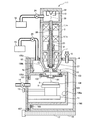
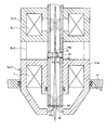
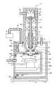
- FIG. 1 shows a configuration diagram of a charged particle beam apparatus (charged particle beam microscope) 111 according to a first embodiment of the present invention.
- an SEM which is an electron beam apparatus
- the present invention relates to other charged particle beam apparatuses (charged particles)
- the present invention can also be applied to a line microscope 111. According to this charged particle beam apparatus (charged particle beam microscope) 111, it is possible to irradiate and observe the charged particle beam on the sample 6 placed under the atmospheric pressure.
- the charged particle beam device 111 includes an electron source 110 for emitting an electron beam (charged particle beam), and an electron optical system (charged particle optical system) such as the electron optical lens 1, the deflection coil 2, and the electron objective lens 7. It has an electron optical lens barrel 3 for holding the electron source 110, and a first housing (sample housing) 4 connected to the electron optical lens barrel 3 for holding and containing the sample 6.
- the electron source 110 is housed in the third housing 22.
- An electron optical system such as the electron optical lens 1, the deflection coil 2 and the electron objective lens 7 focuses an electron beam and controls its optical axis.
- the electron optical lens 1 and the electron objective lens 7 focus the electron beam.
- the deflection coil 2 scans the optical axis 30 of the focused electron beam.
- the electron optical lens barrel 3 is inserted into the first housing 4, and an electron beam is emitted from the electron optical lens barrel 3 to the inside of the first housing 4.
- the first housing 4 and the electron optical lens barrel 3 are in close contact with each other via a vacuum sealing portion 15 such as an O-ring, and the air tightness of the space 105 inside the first housing 4 is secured.
- the first housing 4 is provided with a valve or gas inlet / outlet 5 for air leak inside the housing.
- a detector 8 is provided which detects secondary signals such as secondary electrons and reflected electrons emitted from the sample 6 when the sample 6 is irradiated with an electron beam.
- a first diaphragm 10 In the vicinity of the electron objective lens 7, a first diaphragm 10 through which an electron beam passes is disposed.
- the effect of disposing the first diaphragm 10 in the vicinity of the electron objective lens 7 will be described later.
- the space 20 in the electron optical lens barrel 3 (tube 23) on the upper side of the first diaphragm 10 is separated from the space 105 in the lower first housing 4 by the first diaphragm 10.
- the first diaphragm 10 is disposed on the optical axis 30 of the electron beam.
- the vacuum pump 18 is connected to the third housing 22 via a vacuum valve or vacuum sealing unit 24 and mainly evacuates the space 20 from the electron source 110 to the upper surface of the first diaphragm 10.
- the vacuum pump 19 is connected to the first housing 4 via the valve 25 and mainly evacuates a space 105 from the lower surface of the first diaphragm 10 to the upper surface of a second diaphragm 101 described later.
- the vacuum pump 18 and the vacuum pump 19 may be connected, and each may be one or more than one.
- the attachment housing 100 is attached to the first housing 4.
- the attachment housing 100 has a box-shaped recess 100 a and a flange 100 c provided at the edge of the recess 100 a and having a sealing surface on both sides.
- An opening 4 a is provided in the first housing 4, and a recess 100 a of the attachment housing 100 is inserted into the inside of the first housing 4 from the opening 4 a.
- the recess 100 a is recessed from the opening 4 a of the first housing 4 to the inside of the first housing 4.
- the opening 4 a is closed by the attachment housing 100.
- the seal surface of the first housing 4 provided around the opening 4a and the seal surface of the flange 100c of the attachment housing 100 opposed thereto are in close contact via the vacuum seal portion 106 such as an O-ring, and the first housing The space 105 surrounded by the body 4 and the attachment housing 100 can be decompressed.
- a through hole 100 b is provided on the electron optical lens barrel 3 side of the attachment case 100.
- the through hole 100 b is airtightly closed by a flange 102 provided with a second diaphragm 101 capable of transmitting an electron beam.
- the second diaphragm 101 is disposed on the optical axis 30.
- the second diaphragm 101 isolates the space 104 inside the recess 100 a of the attachment case 100 and the space 105 surrounded by the first case 4 outside and the attachment case 100.
- a vacuum sealing portion 103 is provided on the sealing surfaces of the attachment housing 100 and the flange 102.
- a guard 100d is provided at the edge of the recess 100a on the side where the second diaphragm 101 (flange 102) is disposed.
- the sample 6 can hit the guard 100d and can not be inserted into the recess 100a. Since the guard 100 d is set at a lower position than the second diaphragm 101, the sample 6 can be prevented from hitting the second diaphragm 101 at the time of insertion.
- a stage 11 equipped with a sample holder 9 or the like for holding the sample 6 is supported by a plate member (flange) 12.
- the flange 12 is supported so as to be in close contact with the sealing surface of the flange 100 c of the attachment housing 100 with the vacuum sealing portion 107 such as an O-ring interposed therebetween.
- the flange 12 is supported on the opening 4 a side of the first housing 4.
- a knob 13 for controlling a displacement mechanism such as sliding or tilting of the stage 11 is provided.
- a motor, an actuator, or the like may be provided.
- the flange 12 may be provided with a valve or gas inlet / outlet 14 for performing gas introduction or the like.
- valve or gas inlet / outlet 14 There may be more than one valve or gas inlet / outlet 14. It is also possible to fill the space 104 with a specific gas from the valve or gas inlet / outlet 14 or to decompress the space 104 (vacuum or low vacuum) by connecting the valve or gas inlet / outlet 14 to a vacuum pump It is.
- the sample 6 and the second diaphragm 101 be as close as possible.
- the distance between the second diaphragm 101 and the sample 6 is preferably 1000 ⁇ m or less. This is because the distance of the atmospheric space through which the electron beam emitted by a general SEM acceleration voltage (for example, several tens of kV) can pass is 1000 ⁇ m or less. Therefore, it is more preferable that the stage 11 be provided with a mechanism capable of changing the sample 6 in the height direction. Alternatively, the second diaphragm 101 may move in the direction of the sample 6.
- the replacement of the sample 6 is performed by moving the flange 12 away from the attachment housing 100 (first housing 4) and withdrawing the sample stage 11 from the recess 100a of the attachment housing 100.
- Guides 16 and rails 17 may be provided so that the flange 12 can move smoothly.
- the replacement of the second diaphragm 101 can be performed by putting a hand in the recess 100 a after moving the flange 12 and pulling out the sample stage 11 from the recess 100 a of the attachment housing 100.
- the recess 100 a is pulled out of the opening 4 a of the first housing 4 and the attachment housing 100 is removed from the first housing 4 It may be replaced after that.
- the number of parts to be disassembled for replacement is small, easily accessible, and can be easily replaced.
- the attachment housing 100 is removed from the first housing 4, the sample 6 can be observed in vacuum.
- the flange 12 closes the opening 4 a of the first housing 4.
- the sealing surface of the flange 12 is in close contact with the sealing surface around the opening 4 a of the first housing 4 via the vacuum sealing portion 106. Since the spaces 104 and 105 surrounded by the flange 12 and the first housing 4 can be evacuated by the vacuum pump 19, the sample 6 can be observed under vacuum. Conversely, the sample 6 can be observed under atmospheric pressure (high pressure) simply by attaching the attachment housing 100 with the second diaphragm 101 to a conventional charged particle beam apparatus that usually observes the sample 6 under vacuum. become.
- the space 20 in which the electron source 110 is provided reaches the upper surface of the first diaphragm 10.
- the electron source 110 is provided in a thick third portion 22 having a round cup shape.
- the first diaphragm 10 is disposed at the distal end of a thin round bowl-shaped tube 23 and closes the distal end.
- the other end of the tube 23 is connected to the third housing 22.
- the space in the pipe 23 and the space in the third housing 22 communicate with each other to form one space 20.
- This space 20 is an airtight space that can be evacuated.
- the tube 23 passes through an electron optical system such as the electron optical lens 1, the deflection coil 2, and the electron objective lens 7.
- the tube 23 By thinning the tube 23, it is also possible to reduce the size of the electron optical system such as the electron optical lens 1, the deflection coil 2 and the electron objective lens 7 outside the tube 23. Even if these electron optical systems are made small, the tube 23 is thin and the distance to the central axis of the electron optical system and the tube 23 can be shortened, so that a strong magnetic field can be generated near the central axis of the tube 23. The same applies to the case where a permanent magnet or the like is used in the electron optical system.
- the optical axis 30 of the electron beam passes through the inside of the tube 23.
- An electron optical system such as the electron optical lens 1, the deflection coil 2, and the electron objective lens 7 is basically disposed on the atmosphere side.
- the space 20 inside the tube 23 is vacuum. Since the electromagnetic field is generated in the space 20 from the outside of the tube 23 to the inside, the tube 23 is desirably nonmagnetic.
- the first diaphragm 10 is replaced by closing the valve 25 and opening the valve or gas inlet / outlet 5 to make the space 105 surrounded by the first housing 4 and the attachment housing 100 at atmospheric pressure, and then the third housing
- the body 22 is moved in the extension direction of the optical axis 30, and the tube 23 is pulled out of the electron optical lens barrel 3.
- the replacement of the first diaphragm 10 with the drawn tube 23 can be easily performed because the first diaphragm 10 is exposed.
- the number of parts to be disassembled for replacement is small, easily accessible, and can be easily replaced.
- the first diaphragm 10 can be provided on the optical axis 30 simply by connecting the tube 23 with the first diaphragm 10 to the third housing 22.
- the sample 6 is placed on the sample holder 9 that has been pulled out.
- the sample 6 placed on the sample holder 9 is placed in the recess 100 a of the attachment housing 100, and the flange 12 is fixed in close contact with the flange 100 c of the attachment housing 100.
- an electron beam is emitted from the electron source 110.
- the electron beam passes an electromagnetic field formed by an electron optical system such as the electron optical lens 1, the deflection coil 2, and the electron objective lens 7, and passes through the first diaphragm 10 and the second diaphragm 101.
- the sample 6 is brought close to the second diaphragm 101.
- the electron beam transmitted through the second diaphragm 101 can reach the sample 6 even if it travels through the atmosphere.
- the reached electron beam is irradiated to the sample 6, and the backscattered electrons or secondary electrons are emitted from the sample 6.
- a SEM image is acquired by detecting these with the detector 8.
- the first diaphragm 10 and the second diaphragm 101 are preferably thin because they must transmit the electron beam. If it is too thick, the electron beam is scattered and the resolution is reduced.
- the thickness of the first diaphragm 10 and the second diaphragm 101 is preferably 100 nm or less. This is a thickness that can be transmitted at a common SEM acceleration voltage (for example, several tens of kV).
- silicon, silicon oxide, silicon nitride, silicon carbide, carbon, an organic substance or the like can be used as a material of the first diaphragm 10 and the second diaphragm 101.
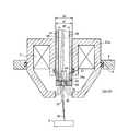
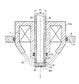
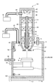
- FIG. 2 shows an enlarged view of the electron objective lens 7 and the vicinity thereof.
- a magnetic core 3 a that forms a part of the electron optical lens barrel 3 is provided.
- a lens effect for focusing the electron beam is generated by the electromagnetic field 36 generated in the vicinity of the gap of the magnetic core 3a.
- the first diaphragm 10 is disposed at the center of the lens in the middle of the electromagnetic field 36 where the magnetic field becomes strong.
- the gap of the magnetic core 3a is open in the vertical direction (the direction of the optical axis 30), and the first diaphragm 10 is disposed at a height substantially in the middle of the gap of the magnetic core 3a.
- the first diaphragm 10 has three functions.
- the first function separates the upper space 20 and the lower space 105 (104) by the first diaphragm 10, and the pressure of the upper space 20 and the pressure of the lower space 105 (104) And so that a pressure difference can occur.
- the space 20 is maintained in a high vacuum state because the electron source 110 (see FIG. 1) is disposed. Since the first diaphragm 10 is attached to the tube 23, the space 20 in a high vacuum state can be brought closer to the sample 6 side. Even if the degree of vacuum in the space 105 is bad, the electron beam can reach the sample 6 (the second diaphragm 101 (see FIG. 1)).
- an inexpensive and simple vacuum pump can be used as the vacuum pump 19 (see FIG. 1), instead of a high-performance vacuum pump for high vacuum.
- the second function is to prevent the flow of air into the space 105 and prevent the flow into the space 20 even if the second diaphragm 101 (see FIG. 1) is broken. This can prevent the filament of the electron source 110 from burning out.
- the airtightness of the space 105 is secured by bringing the outer peripheral surface of the tube 23 into close contact with the inner peripheral surface of the magnetic core 3a (electron optical lens barrel 3) via a vacuum sealing portion 27 such as an O-ring. ing.
- the outer diameter d1 of the tube 23 is smaller than the inner diameter d3 of the electron optical system such as the electron optical lens 1 (see FIG. 1), the deflection coil 2 and the electron objective lens 7 (d1 ⁇ d3). Therefore, the tube 23 can be removed together with the first diaphragm 10 from the electron optical lens barrel 3 holding the electron optical system such as the electron optical lens 1, the deflection coil 2 and the electron objective lens 7.
- the third function is the function of a stop that cuts the electron beam away from the optical axis 30.
- the trajectory 32 of the electron beam away from the optical axis 30 is largely bent by the strong electromagnetic field by the electron objective lens 7.
- the trajectory 33 of the electron beam passing near the optical axis 30 is deviated on the sample 6.
- a partition plate (diaphragm holding portion) 34 in which a through hole 34a having a diameter d4 smaller than the inner diameter d2 of the pipe 23 is formed is provided in the pipe 23 (d4 ⁇ d2).
- the partition plate 34 isolates the space 20 in the tube 23 (electron optical lens barrel 3) and the space 105 in the first housing 4.
- the partition plate 34 is thicker than the first diaphragm 10 and does not transmit electron beams.
- the first diaphragm 10 is provided to close the through hole 34 a provided in the partition plate 34.
- the through holes 34 a are disposed near the center (optical axis 30) of the partition plate 34.
- the partition plate 34 and the tube 23 are fixed and vacuum sealed with an adhesive 35. Since the partition plate 34 is charged by the electron beam of the track 32, it is desirable to have conductivity.
- the first diaphragm 10 Since the first diaphragm 10 is charged by the electron beam of the track 33, it is desirable that the first diaphragm 10 have conductivity. Further, in order to ground the first diaphragm 10 and the partition plate 34, it is desirable that the adhesive 35 and the tube 23 also have conductivity. Further, since the first diaphragm 10, the partition plate 34 and the adhesive 35 are placed in the electromagnetic field 36, it is desirable that they be nonmagnetic.
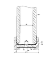
- FIG. 3 shows an enlarged view of the first diaphragm 10 and the vicinity thereof according to a modification (Part 1) of the first embodiment.
- the end face of the tube 23 is used as a sealing surface, and is closely attached to the partition plate 34 via the vacuum sealing portion 38.
- the outer peripheral surface of the tip of the pipe 23 is threaded, and by screwing with the screw thread 39 cut in the fixing member 37, the fixing member 37 is in pressure contact with the partition plate 34 in the direction of the pipe 23.
- the partition plate 34 is in close contact with the end face of the pipe 23.
- the outer diameter of the fixing member 37 is larger than the outer diameter of the tube 23, the outer diameter d11 of the fixing member 37 is that of an electron optical system such as the electron optical lens 1, the deflection coil 2 or the electron objective lens 7.
- the diameter is made smaller than the inner diameter d3 (d11 ⁇ d3).
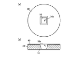
- FIG. 4A (a) shows a plan view of the first diaphragm 10 of the first embodiment and the vicinity thereof, and (b) shows a cross-sectional view in the radial direction of (a).
- a partition plate 34 is formed on the first diaphragm 10, and a conductive or semiconductive film 40 is formed on the partition plate 34.
- Through holes 34 a are provided in the partition plate 34 and the film 40.
- the through hole 34 a is closed by the first diaphragm 10.
- the first diaphragm 10 and the film 40 are formed on each surface of the partition plate 34, the through holes 34 a are formed in the film 40, and the through holes 34 a are also formed in the partition plate 34, It can be made.
- the through holes 34a are substantially circular in plan view, as shown in FIG. 4A (a). According to this, it is possible to reduce spherical aberration uniformly in the circumferential direction. Since the film 40 is irradiated with the electron beam on the surface of the partition plate 34, the film 40 is provided so that the charge is not accumulated on the surface. The film 40 can be formed by vapor deposition.
- the second diaphragm 101 may have the same structure as that of the first diaphragm 10.
- FIG. 4B (a) shows a plan view of the first diaphragm 10 of the modified example (part 2) of the first embodiment and the vicinity thereof, and (b) shows a cross-sectional view in the radial direction of (a).
- the modification (part 2) of the first embodiment is different from the first embodiment in that, as shown in FIG. 4B (a), the through holes 34a become substantially quadrangle in a plan view. That is the point. Further, as shown in FIGS. 4B (a) and (b), the side walls of the through holes 34a are tapered. Such a shape is obtained when a single crystal substrate such as silicon is used for the partition plate 34.
- the etching rate varies depending on the crystal orientation, so the quadrangle and the taper appear. Since the microfabrication technology of a single crystal substrate such as silicon is established, it can be used when it is desired to reduce the diameter of the through hole 34a.
- the diameter (width) of the through hole 34a is, for example, about several tens of ⁇ m to 1 mm.
- the thickness of the first diaphragm 10 is preferably thin because the electron beam must be transmitted, but the diameter (area) of the through hole 34a is small in order to secure the strength of the first diaphragm 10 even if it is thin. Must. What thickness and area are good depends on the resolution and aperture size required for observation.
- FIG. 5 shows an enlarged view of the electron objective lens 7 and the vicinity thereof according to a modification (part 3) of the first embodiment.
- a magnetic core 3 a that forms a part of the electron optical lens barrel 3 is provided.
- a lens effect for focusing the electron beam is generated by the electromagnetic field 36 generated in the vicinity of the gap of the magnetic core 3a.
- the electromagnetic field 36 exudes to the lower side (the sample 6 (see FIG. 1) side) of the magnetic core 3a, and is a so-called semi-in-lens system.
- the first diaphragm 10 is disposed below the electromagnetic field 36 at the lens center where the magnetic field is strongest.
- the gap of the magnetic core 3a is open substantially in the radial direction (direction substantially perpendicular to the optical axis 30), and the first diaphragm 10 is disposed at a position lower than the height of the gap of the magnetic core 3a.
- the gap of the magnetic core 3a is open in the vertical direction (direction of the optical axis 30), and the first diaphragm 10 is the gap of the magnetic core 3a. It is placed at about the middle height of the.
- the electromagnetic field 36 does not ooze out to the lower side (the sample 6 (see FIG. 1) side) of the magnetic core 3a, and has a so-called out lens system.
- the height of the first diaphragm 10 can be made lower than the magnetic core 3a, and the first diaphragm 10 is brought closer to the sample 6 (see FIG. 1) or the second diaphragm 101. be able to. Then, the high vacuum space 20 including the electron source 110 (see FIG. 1) can be brought close to the sample 6 and the second diaphragm 101.
- FIG. 6 shows an enlarged view of the electron objective lens 7 of the modified example (part 4) of the first embodiment and the vicinity thereof.
- the first diaphragm 10 is disposed at the lens center where the magnetic field is strongest in the electromagnetic field 36 formed by the electron objective lens 7.
- it is disposed between the electron source 110 and the electron objective lens 7. Specifically, it may be disposed at the lens center where the magnetic field is strongest in the electromagnetic field 36 formed by the electron optical lens (condenser lens) 1 (1a, 1b, see FIG. 1).
- the crossover position 41 (see FIG. 6) at which the electron beam is focused between the electron optical lens 1b and the electron objective lens 7 in the first diaphragm 10. The case where it arranges to) is explained.
- a magnetic core 3c forming a part of the electron optical lens barrel 3 is provided around the electron optical lens 1b.
- a lens effect for focusing the electron beam is generated by the electromagnetic field generated near the gap of the magnetic core 3c.
- the magnetic core 3c is supported by the magnetic core 3a via the support cylinder 3b.
- the first diaphragm 10 When the first diaphragm 10 is disposed at the crossover position 41, the electron beam is narrowed to one point and incident on the first diaphragm 10, so the diameter (area) of the through hole 34a of the partition plate 34 can be reduced. It becomes possible. Therefore, the first diaphragm 10 can be thinned while maintaining the durability.
- a shielding plate 44 in which a through hole 44a is formed may be disposed as an objective stop.
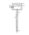
- FIG. 7A shows a configuration of the tube 23 extracted from the main body of the charged particle beam device 111 of the first embodiment and the vicinity thereof
- FIG. 7B shows the main body of the charged particle beam device 111 from which the tube 23 is extracted.
- a block diagram is shown.
- FIG. 7A when the vacuum valve or vacuum sealing unit 24 is closed and the vacuum valve or vacuum sealing unit 24 is separated from the vacuum pump 18, the space 20 inside the third housing 22 and the tube 23 is closed. It can be removed from the main body of the charged particle beam device 111 while maintaining the vacuum. Then, the first diaphragm 10 can be exchanged while connecting the vacuum valve or the vacuum sealing unit 24 to the gas cylinder and flowing the dried inert gas.
- the vacuum pump 18 is connected to the vacuum valve or vacuum sealing unit 24, and the space 20 is evacuated. Before and after this evacuation, a tube 23 with a first diaphragm 10 is inserted from above the electron optical lens barrel 3. Thus, the tube 23 with the first diaphragm 10 is detachable from the electron optical lens barrel 3.
- tube 23 extracted from the main body of the charged particle beam apparatus (microscope) of the modification (the 5) of 1st Embodiment at FIG. 8 is shown. Since a high voltage of several kilovolts to several tens of kilovolts is usually applied to the electron source 110, the electron source 110 is set to a predetermined side wall of the third housing 22 in order to secure the withstand voltage with the third housing 22. It must be separated by a distance. Therefore, as shown in FIG. 7A, in the first embodiment, the third housing 22 is thicker than the pipe 23. However, when the acceleration voltage may be low, as shown in FIG. 8, all tubes 23 may have the same thickness.
- the height at which the first diaphragm 10 should be disposed can be uniquely determined by the third housing 22 contacting the electron optical lens barrel 3. In addition, by interposing a spacer between the third housing 22 and the electron optical lens barrel 3, the height at which the first diaphragm 10 should be disposed can be adjusted. In the modification (part 5) of the first embodiment, the depth at which the tube 23 is inserted into the electron optical lens barrel 3 can be arbitrarily adjusted. Therefore, the height at which the first diaphragm 10 is to be disposed can be arbitrarily adjusted.
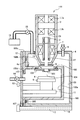
- FIG. 9 shows a configuration diagram of the charged particle beam device 111 according to the modification (part 6) of the first embodiment.
- the sixth modification of the first embodiment is different from the first embodiment in that a non-evaporable getter material 45 is provided in the third housing 22.
- the getter material 45 can adsorb the gas in the space 20 to maintain a vacuum state. For this reason, the vacuum pump 18 capable of reaching high vacuum can be omitted.
- a roughing pump is connected to a vacuum valve or vacuum sealing unit 24 to evacuate the space 20 although the vacuum is low. Thereafter, the vacuum valve or vacuum seal portion 24 is closed, the pump is removed, and the getter 45 raises the pressure to a high vacuum.
- the modification (part 6) of the first embodiment since the vacuum pump 18 can be omitted at the time of normal observation, the charged particle beam device 111 can be miniaturized at the time of normal observation.
- FIG. 10 shows a configuration diagram of a charged particle beam apparatus (microscope) 111 according to a second embodiment of the present invention.
- the second embodiment differs from the first embodiment in that the attachment housing 100 with the second diaphragm 101 is removed.
- the space 21 (corresponding to the space 104 and the space 105 in the first embodiment) surrounded by the first housing 4 and the flange 12 is in a vacuum state.
- the sample 6 placed in the space 21 can be observed under vacuum.
- a gas can be introduced into the space 21 from the gas inlet / outlet 5 or 14, and the sample 6 can be SEM-observed in a low vacuum state. .
- the space 20 can be held at high vacuum by the first diaphragm 10.
- the first diaphragm 10 can be easily replaced as in the first embodiment.
- the pressure in the first housing 4 becomes atmospheric pressure. Therefore, when the observation and the replacement of the sample 6 are repeated on the first diaphragm 10, atmospheric pressure does not act or not, and the durability of the first diaphragm 10 does not fluctuate in the first embodiment. It is considered to be lower than the Therefore, when the charged particle beam device 111 is used in the second embodiment or used in combination of the first embodiment and the second embodiment, it is used in the first embodiment. It is desirable to use the 1st diaphragm 10 which improved durability compared with. In order to enhance the durability, the thickness of the first diaphragm 10 may be increased, or the diameter of the through hole 34 a of the partition plate 34 may be reduced.
- Electron optical lens (electron (charged particle) optical system, condenser lens) 2 Deflection coil (electron (charged particle) optical system) 3 Electron optics (charged particle optics) barrel 3a Magnetic core 3b Support cylinder 3c Magnetic core 4 1st case (sample case) 4a 1st case opening 5 valve or gas inlet / outlet 6 sample 7 electron objective lens (electron (charged particle) optical system) 8 detector 9 sample holder 10 first diaphragm 11 sample stage 12 plate member with stage (flange) 13 Stage position adjustment knob 14 Valve or gas inlet / outlet 15 Vacuum seal part 16 Guide 17 Rail 18, 19 Vacuum pump 20 Space between the electron source 110 and the first diaphragm 10 (space in the lens barrel) 21 Sample atmosphere space (space in the first case) 22 3rd Case (Round shaped part) 23 tube (round-shaped bowl) 24 vacuum valve or vacuum sealing unit 25 valve 27 vacuum sealing unit 30 optical axis 32 charged particle beam (orbital path passing
Landscapes
- Chemical & Material Sciences (AREA)
- Analytical Chemistry (AREA)
- Analysing Materials By The Use Of Radiation (AREA)
Priority Applications (4)
| Application Number | Priority Date | Filing Date | Title |
|---|---|---|---|
| CN201380008021.1A CN104094373B (zh) | 2012-02-27 | 2013-02-15 | 带电粒子线装置 |
| KR1020147021504A KR101607043B1 (ko) | 2012-02-27 | 2013-02-15 | 하전 입자선 장치 |
| US14/379,291 US9208995B2 (en) | 2012-02-27 | 2013-02-15 | Charged particle beam apparatus |
| DE112013000696.0T DE112013000696B4 (de) | 2012-02-27 | 2013-02-15 | Ladungsteilchenstrahlvorrichtung |
Applications Claiming Priority (2)
| Application Number | Priority Date | Filing Date | Title |
|---|---|---|---|
| JP2012-039500 | 2012-02-27 | ||
| JP2012039500A JP5836838B2 (ja) | 2012-02-27 | 2012-02-27 | 荷電粒子線装置 |
Publications (1)
| Publication Number | Publication Date |
|---|---|
| WO2013129143A1 true WO2013129143A1 (ja) | 2013-09-06 |
Family
ID=49082344
Family Applications (1)
| Application Number | Title | Priority Date | Filing Date |
|---|---|---|---|
| PCT/JP2013/053737 Ceased WO2013129143A1 (ja) | 2012-02-27 | 2013-02-15 | 荷電粒子線装置 |
Country Status (6)
| Country | Link |
|---|---|
| US (1) | US9208995B2 (enExample) |
| JP (1) | JP5836838B2 (enExample) |
| KR (1) | KR101607043B1 (enExample) |
| CN (1) | CN104094373B (enExample) |
| DE (1) | DE112013000696B4 (enExample) |
| WO (1) | WO2013129143A1 (enExample) |
Cited By (3)
| Publication number | Priority date | Publication date | Assignee | Title |
|---|---|---|---|---|
| JP2014075365A (ja) * | 2014-01-27 | 2014-04-24 | Hitachi High-Technologies Corp | 荷電粒子線装置、試料画像取得方法、およびプログラム記録媒体 |
| JP2016146362A (ja) * | 2016-05-16 | 2016-08-12 | 株式会社日立ハイテクノロジーズ | 荷電粒子線装置、試料画像取得方法、およびプログラム記録媒体 |
| WO2019116605A1 (ja) * | 2017-12-13 | 2019-06-20 | 株式会社日立ハイテクノロジーズ | 電子線照射装置、分析システム |
Families Citing this family (17)
| Publication number | Priority date | Publication date | Assignee | Title |
|---|---|---|---|---|
| JP6035602B2 (ja) * | 2012-11-21 | 2016-11-30 | 株式会社日立ハイテクノロジーズ | 荷電粒子線装置、試料台ユニット、及び試料観察方法 |
| KR101554594B1 (ko) * | 2013-12-02 | 2015-09-22 | 한국표준과학연구원 | 하전입자 빔 프로브 형성 장치 및 이의 이용방법 |
| JP6302702B2 (ja) * | 2014-02-27 | 2018-03-28 | 株式会社日立ハイテクノロジーズ | 走査電子顕微鏡および画像生成方法 |
| JP6491890B2 (ja) * | 2015-01-21 | 2019-03-27 | 株式会社日立ハイテクノロジーズ | 荷電粒子線装置 |
| KR101663730B1 (ko) * | 2015-03-23 | 2016-10-10 | 한국원자력연구원 | 차등진공을 이용한 하전입자빔 대기인출장치 |
| KR101682522B1 (ko) * | 2015-06-02 | 2016-12-06 | 참엔지니어링(주) | 시료 관찰 방법 |
| KR101756171B1 (ko) * | 2015-12-15 | 2017-07-12 | (주)새론테크놀로지 | 주사 전자 현미경 |
| KR102271660B1 (ko) | 2017-04-11 | 2021-07-01 | 주식회사 아도반테스토 | 노광 장치 |
| WO2018189816A1 (ja) | 2017-04-11 | 2018-10-18 | 株式会社アドバンテスト | 露光装置 |
| US11621144B2 (en) * | 2018-08-03 | 2023-04-04 | Nuflare Technology, Inc. | Electron optical system and multi-beam image acquiring apparatus |
| US10998166B2 (en) * | 2019-07-29 | 2021-05-04 | Fei Company | System and method for beam position visualization |
| KR102552225B1 (ko) * | 2020-02-04 | 2023-07-06 | (주)새론테크놀로지 | 주사 전자 현미경 |
| JP7430909B2 (ja) * | 2020-08-19 | 2024-02-14 | 株式会社ブイ・テクノロジー | 集束イオンビーム装置 |
| WO2022048898A1 (en) * | 2020-09-07 | 2022-03-10 | Asml Netherlands B.V. | Electron-optical assembly comprising electromagnetic shielding |
| DE102020124306B4 (de) * | 2020-09-17 | 2022-08-11 | Carl Zeiss Smt Gmbh | Vorrichtung zum Analysieren und/oder Bearbeiten einer Probe mit einem Teilchenstrahl und Verfahren |
| CN112397300B (zh) * | 2020-10-26 | 2022-03-25 | 南京新康达磁业股份有限公司 | 一种金属磁粉心粉末的无机绝缘粘接设备及其粘接方法 |
| EP4156227A1 (en) * | 2021-09-27 | 2023-03-29 | ASML Netherlands B.V. | Charged particle apparatus and method |
Citations (6)
| Publication number | Priority date | Publication date | Assignee | Title |
|---|---|---|---|---|
| JPH02139842A (ja) * | 1988-11-18 | 1990-05-29 | Nikon Corp | 電子線装置 |
| JP2006318903A (ja) * | 2005-05-09 | 2006-11-24 | Lee Bing Huan | 真空または低圧環境下で気体の操作および観察を可能にする装置 |
| JP2007305499A (ja) * | 2006-05-15 | 2007-11-22 | Hitachi High-Technologies Corp | 差動排気走査形電子顕微鏡 |
| JP2008262886A (ja) * | 2007-04-12 | 2008-10-30 | Beam Seiko:Kk | 走査型電子顕微鏡装置 |
| JP2010056011A (ja) * | 2008-08-29 | 2010-03-11 | Jeol Ltd | 粒子線装置 |
| JP2010509709A (ja) * | 2006-10-24 | 2010-03-25 | ビー・ナノ・リミテッド | インターフェース、非真空環境内で物体を観察する方法、および走査型電子顕微鏡 |
Family Cites Families (8)
| Publication number | Priority date | Publication date | Assignee | Title |
|---|---|---|---|---|
| JP4528014B2 (ja) * | 2004-04-05 | 2010-08-18 | 株式会社日立ハイテクノロジーズ | 試料検査方法 |
| JP2006147430A (ja) * | 2004-11-22 | 2006-06-08 | Hokkaido Univ | 電子顕微鏡 |
| JP2008153086A (ja) | 2006-12-19 | 2008-07-03 | Jeol Ltd | 試料検査装置及び試料検査方法並びに試料検査システム |
| EP2365321B1 (en) | 2006-12-19 | 2013-10-02 | JEOL Ltd. | Sample inspection apparatus, sample inspection method, and sample inspection system |
| WO2010001399A1 (en) | 2008-07-03 | 2010-01-07 | B-Nano | A scanning electron microscope, an interface and a method for observing an object within a non-vacuum environment |
| CN102197301B (zh) * | 2008-09-28 | 2015-05-06 | B-纳诺有限公司 | 被抽真空的装置和扫描电子显微镜 |
| JP2010230417A (ja) | 2009-03-26 | 2010-10-14 | Jeol Ltd | 試料の検査装置及び検査方法 |
| JP2013020918A (ja) * | 2011-07-14 | 2013-01-31 | Hitachi High-Technologies Corp | 荷電粒子線装置 |
-
2012
- 2012-02-27 JP JP2012039500A patent/JP5836838B2/ja not_active Expired - Fee Related
-
2013
- 2013-02-15 WO PCT/JP2013/053737 patent/WO2013129143A1/ja not_active Ceased
- 2013-02-15 CN CN201380008021.1A patent/CN104094373B/zh not_active Expired - Fee Related
- 2013-02-15 US US14/379,291 patent/US9208995B2/en active Active
- 2013-02-15 KR KR1020147021504A patent/KR101607043B1/ko not_active Expired - Fee Related
- 2013-02-15 DE DE112013000696.0T patent/DE112013000696B4/de not_active Expired - Fee Related
Patent Citations (6)
| Publication number | Priority date | Publication date | Assignee | Title |
|---|---|---|---|---|
| JPH02139842A (ja) * | 1988-11-18 | 1990-05-29 | Nikon Corp | 電子線装置 |
| JP2006318903A (ja) * | 2005-05-09 | 2006-11-24 | Lee Bing Huan | 真空または低圧環境下で気体の操作および観察を可能にする装置 |
| JP2007305499A (ja) * | 2006-05-15 | 2007-11-22 | Hitachi High-Technologies Corp | 差動排気走査形電子顕微鏡 |
| JP2010509709A (ja) * | 2006-10-24 | 2010-03-25 | ビー・ナノ・リミテッド | インターフェース、非真空環境内で物体を観察する方法、および走査型電子顕微鏡 |
| JP2008262886A (ja) * | 2007-04-12 | 2008-10-30 | Beam Seiko:Kk | 走査型電子顕微鏡装置 |
| JP2010056011A (ja) * | 2008-08-29 | 2010-03-11 | Jeol Ltd | 粒子線装置 |
Cited By (5)
| Publication number | Priority date | Publication date | Assignee | Title |
|---|---|---|---|---|
| JP2014075365A (ja) * | 2014-01-27 | 2014-04-24 | Hitachi High-Technologies Corp | 荷電粒子線装置、試料画像取得方法、およびプログラム記録媒体 |
| WO2015111307A1 (ja) * | 2014-01-27 | 2015-07-30 | 株式会社 日立ハイテクノロジーズ | 荷電粒子線装置、試料画像取得方法、およびプログラム記録媒体 |
| US9741530B2 (en) | 2014-01-27 | 2017-08-22 | Hitachi High-Technologies Corporation | Charged-particle-beam device, specimen-image acquisition method, and program recording medium |
| JP2016146362A (ja) * | 2016-05-16 | 2016-08-12 | 株式会社日立ハイテクノロジーズ | 荷電粒子線装置、試料画像取得方法、およびプログラム記録媒体 |
| WO2019116605A1 (ja) * | 2017-12-13 | 2019-06-20 | 株式会社日立ハイテクノロジーズ | 電子線照射装置、分析システム |
Also Published As
| Publication number | Publication date |
|---|---|
| CN104094373A (zh) | 2014-10-08 |
| DE112013000696B4 (de) | 2018-08-02 |
| KR101607043B1 (ko) | 2016-03-28 |
| JP5836838B2 (ja) | 2015-12-24 |
| US20150014530A1 (en) | 2015-01-15 |
| DE112013000696T5 (de) | 2014-10-09 |
| US9208995B2 (en) | 2015-12-08 |
| CN104094373B (zh) | 2016-08-17 |
| JP2013175377A (ja) | 2013-09-05 |
| KR20140119078A (ko) | 2014-10-08 |
Similar Documents
| Publication | Publication Date | Title |
|---|---|---|
| JP5836838B2 (ja) | 荷電粒子線装置 | |
| US5254856A (en) | Charged particle beam apparatus having particular electrostatic objective lens and vacuum pump systems | |
| JP5677310B2 (ja) | 荷電粒子顕微鏡 | |
| KR100286084B1 (ko) | 하전 입자빔 장치 | |
| US20140123898A1 (en) | Charged particle beam device | |
| JP2008192617A (ja) | 粒子と光子で同時に試料を観察する粒子光学装置 | |
| WO2009062929A2 (en) | Beam device and system comprising a particle beam device and an optical microscope | |
| WO2011001797A1 (ja) | ガス電界電離イオン源装置およびこれを搭載した走査荷電粒子顕微鏡 | |
| JP2008262886A (ja) | 走査型電子顕微鏡装置 | |
| JP2004031207A (ja) | 電子線照射装置および走査型電子顕微鏡装置 | |
| JP4262158B2 (ja) | 低真空走査電子顕微鏡 | |
| JPS5938701B2 (ja) | 二段試料台を備えた走査型電子顕微鏡 | |
| US10340117B2 (en) | Ion beam device and sample observation method | |
| US20080073534A1 (en) | Scanning electron microscope | |
| JPH0498746A (ja) | 荷電粒子線装置 | |
| JP5993356B2 (ja) | 走査型電子顕微鏡 | |
| KR102839263B1 (ko) | 대물 렌즈 커버 및 이를 포함하는 하전입자선 장치 | |
| JP7307768B2 (ja) | 走査電子顕微鏡および対物レンズ | |
| JPH0451439A (ja) | 荷電粒子線装置 | |
| JP2746573B2 (ja) | 荷電粒子線装置 | |
| JPH08250058A (ja) | 走査形電子顕微鏡 | |
| TW202236342A (zh) | 帶電粒子束設備、掃描電子顯微鏡和操作帶電粒子束設備的方法 | |
| JP2025023784A (ja) | 対物レンズ及びそれを含む荷電粒子線装置 |
Legal Events
| Date | Code | Title | Description |
|---|---|---|---|
| 121 | Ep: the epo has been informed by wipo that ep was designated in this application |
Ref document number: 13754671 Country of ref document: EP Kind code of ref document: A1 |
|
| ENP | Entry into the national phase |
Ref document number: 20147021504 Country of ref document: KR Kind code of ref document: A |
|
| WWE | Wipo information: entry into national phase |
Ref document number: 14379291 Country of ref document: US |
|
| WWE | Wipo information: entry into national phase |
Ref document number: 112013000696 Country of ref document: DE Ref document number: 1120130006960 Country of ref document: DE |
|
| 122 | Ep: pct application non-entry in european phase |
Ref document number: 13754671 Country of ref document: EP Kind code of ref document: A1 |