WO2013051568A1 - アプリケータ - Google Patents
アプリケータ Download PDFInfo
- Publication number
- WO2013051568A1 WO2013051568A1 PCT/JP2012/075534 JP2012075534W WO2013051568A1 WO 2013051568 A1 WO2013051568 A1 WO 2013051568A1 JP 2012075534 W JP2012075534 W JP 2012075534W WO 2013051568 A1 WO2013051568 A1 WO 2013051568A1
- Authority
- WO
- WIPO (PCT)
- Prior art keywords
- piston
- applicator
- spring
- transmission member
- microneedle array
- Prior art date
Links
Images


Classifications
-
- A—HUMAN NECESSITIES
- A61—MEDICAL OR VETERINARY SCIENCE; HYGIENE
- A61M—DEVICES FOR INTRODUCING MEDIA INTO, OR ONTO, THE BODY; DEVICES FOR TRANSDUCING BODY MEDIA OR FOR TAKING MEDIA FROM THE BODY; DEVICES FOR PRODUCING OR ENDING SLEEP OR STUPOR
- A61M37/00—Other apparatus for introducing media into the body; Percutany, i.e. introducing medicines into the body by diffusion through the skin
- A61M37/0015—Other apparatus for introducing media into the body; Percutany, i.e. introducing medicines into the body by diffusion through the skin by using microneedles
-
- A—HUMAN NECESSITIES
- A61—MEDICAL OR VETERINARY SCIENCE; HYGIENE
- A61B—DIAGNOSIS; SURGERY; IDENTIFICATION
- A61B5/00—Measuring for diagnostic purposes; Identification of persons
- A61B5/15—Devices for taking samples of blood
- A61B5/151—Devices specially adapted for taking samples of capillary blood, e.g. by lancets, needles or blades
- A61B5/15101—Details
- A61B5/15115—Driving means for propelling the piercing element to pierce the skin, e.g. comprising mechanisms based on shape memory alloys, magnetism, solenoids, piezoelectric effect, biased elements, resilient elements, vacuum or compressed fluids
- A61B5/15117—Driving means for propelling the piercing element to pierce the skin, e.g. comprising mechanisms based on shape memory alloys, magnetism, solenoids, piezoelectric effect, biased elements, resilient elements, vacuum or compressed fluids comprising biased elements, resilient elements or a spring, e.g. a helical spring, leaf spring, or elastic strap
-
- A—HUMAN NECESSITIES
- A61—MEDICAL OR VETERINARY SCIENCE; HYGIENE
- A61B—DIAGNOSIS; SURGERY; IDENTIFICATION
- A61B5/00—Measuring for diagnostic purposes; Identification of persons
- A61B5/15—Devices for taking samples of blood
- A61B5/150977—Arrays of piercing elements for simultaneous piercing
- A61B5/150984—Microneedles or microblades
-
- A—HUMAN NECESSITIES
- A61—MEDICAL OR VETERINARY SCIENCE; HYGIENE
- A61M—DEVICES FOR INTRODUCING MEDIA INTO, OR ONTO, THE BODY; DEVICES FOR TRANSDUCING BODY MEDIA OR FOR TAKING MEDIA FROM THE BODY; DEVICES FOR PRODUCING OR ENDING SLEEP OR STUPOR
- A61M37/00—Other apparatus for introducing media into the body; Percutany, i.e. introducing medicines into the body by diffusion through the skin
- A61M37/0015—Other apparatus for introducing media into the body; Percutany, i.e. introducing medicines into the body by diffusion through the skin by using microneedles
- A61M2037/0023—Drug applicators using microneedles
-
- A—HUMAN NECESSITIES
- A61—MEDICAL OR VETERINARY SCIENCE; HYGIENE
- A61M—DEVICES FOR INTRODUCING MEDIA INTO, OR ONTO, THE BODY; DEVICES FOR TRANSDUCING BODY MEDIA OR FOR TAKING MEDIA FROM THE BODY; DEVICES FOR PRODUCING OR ENDING SLEEP OR STUPOR
- A61M37/00—Other apparatus for introducing media into the body; Percutany, i.e. introducing medicines into the body by diffusion through the skin
- A61M37/0015—Other apparatus for introducing media into the body; Percutany, i.e. introducing medicines into the body by diffusion through the skin by using microneedles
- A61M2037/0046—Solid microneedles
-
- A—HUMAN NECESSITIES
- A61—MEDICAL OR VETERINARY SCIENCE; HYGIENE
- A61M—DEVICES FOR INTRODUCING MEDIA INTO, OR ONTO, THE BODY; DEVICES FOR TRANSDUCING BODY MEDIA OR FOR TAKING MEDIA FROM THE BODY; DEVICES FOR PRODUCING OR ENDING SLEEP OR STUPOR
- A61M37/00—Other apparatus for introducing media into the body; Percutany, i.e. introducing medicines into the body by diffusion through the skin
- A61M37/0015—Other apparatus for introducing media into the body; Percutany, i.e. introducing medicines into the body by diffusion through the skin by using microneedles
- A61M2037/0061—Methods for using microneedles
Definitions
- One embodiment of the present invention relates to an applicator used to assist administration of an active ingredient by a microneedle.
- Patent Document 1 discloses an apparatus main body, a piston for causing a penetrating member to collide with the stratum corneum, an impact spring for applying an impact force to the piston, and a pressing spring that acts between the apparatus main body and a cap.
- An applicator is described that includes a locking mechanism for cocking the piston by compressing the device body and the piston together using a compressive force and locking the piston in the cocked position.
- Patent Document 2 an applicator having a housing, a piston movable within the housing, and a cap is described.
- Patent Document 3 describes a puncture device for puncturing a puncture head equipped with an infusion cannula or a puncture tip for puncturing a patient's body. This device comprises two operating members that need to be operated simultaneously to trigger the puncture movement.
- Patent Document 4 describes a puncture device in which at least one end portion of the drive spring is arranged so as not to be fixed to either the housing side contact portion or the piston.
- the user can efficiently administer the active ingredient by using the applicator as described above.
- the applicator gives a certain level of impact to the skin, there is a fear that the user may have a fear of applying the microneedle using the applicator. Therefore, when applying the microneedle, it is required to efficiently administer the active ingredient without giving fear to the user.
- An applicator is an applicator for applying microneedles to the skin, and a biasing member is attached to a microneedle array having microneedles having a needle density of 500 needles / cm 2 or more.
- a transmission member for transmitting a force is provided, the mass of the transmission member is 1.5 g or less, and the momentum of the transmission member operated by the urging force of the urging member is 0.0083 (Ns) or more and 0.015 (Ns) or less. It is characterized by that.
- the transmission member that transmits the urging force necessary for puncturing to the microneedle array is very light, the impact that the user feels when operating the applicator is small. Therefore, the user can receive administration using the applicator with peace of mind.
- the momentum of the transmission member and the needle density of the microneedle as described above, the active ingredient is efficiently administered even when the transmission member is lightened so as not to give the user a fear. be able to.
- the amount of transfer of the active ingredient applied to the microneedle to the skin may be proportional to the momentum of the transmission member.
- the biasing member is an elastic member, and in the first section that is a part of the moving section of the transmission member that moves toward the skin, the transmission member is a biasing force of the elastic member. You may move without receiving.
- the applicator according to another embodiment further includes a support base that supports the elastic member and transmits the urging force to the transmission member in the second section different from the first section, and pushes the transmission member by the urging force.
- the support base stops at one end of the second section, the transmission member may move without receiving a biasing force in the first section.
- biasing member of the applicator may be a cylindrical coil spring.
- the active ingredient can be efficiently administered without giving fear to the user when the microneedle is applied.
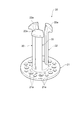
- FIG. 1 is a perspective view from above of an applicator according to an embodiment.
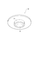
- FIG. 2 is a perspective view from below of the applicator shown in FIG.
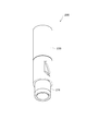
- FIG. 3 is a perspective view of the piston shown in FIG.
- FIG. 4 is a perspective view of the cap shown in FIG. 5 is a cross-sectional view taken along line VV in FIG.
- FIG. 6 is a cross-sectional view illustrating a state in which the claw portion illustrated in FIG. 5 is fixed.
- FIG. 7 is a perspective view of the microneedle array.
- FIG. 8 is a view for explaining a case where an auxiliary tool is used when the applicator shown in FIG. 1 is used.
- FIG. 9 is a diagram for explaining a method of using the applicator shown in FIG. FIG.
- FIG. 10 is a graph showing the relationship between the piston momentum and the OVA transition rate in the example.
- FIG. 11 is a graph showing the relationship between the kinetic energy density of the piston and the OVA transfer rate in the example.
- FIG. 12 is a graph showing the relationship between the piston momentum and the OVA transition amount in the example.
- FIG. 13A is a perspective view of an applicator according to a modification, and FIG. 13B is a cross-sectional view taken along the line BB of FIG. 13A.
- FIG. 14 is a perspective view of an applicator according to another modification.
- 15 is a cross-sectional view taken along line XV-XV in FIG.
- FIG. 1 is a perspective view of the applicator 10 from above.
- FIG. 2 is a perspective view of the applicator 10 from below.
- FIG. 3 is a perspective view of the piston 20.
- FIG. 4 is a perspective view of the cap 30.
- 5 is a cross-sectional view taken along the line VV of FIG. 2, and
- FIG. 6 is a cross-sectional view showing a state where the claw portion shown in FIG. 5 is fixed.
- the housing 11 of the applicator 10 has a cylindrical shape.
- casing may be changed or the surface of a housing
- a cylindrical casing having a polygonal cross section may be used, the outer wall may be rounded as a whole, or a depression or a step may be provided in the cylindrical casing.
- a piston 20 for impacting the microneedle array applied to the skin is accommodated near the one end of the housing 11 (see FIG. 2).
- a cap 30 for operating the piston 20 is accommodated near the other end of the housing 11 (see FIG. 1).
- the side in which the cap 30 is accommodated is defined as the upper side of the applicator 10 or the casing 11
- the side in which the piston 20 is accommodated is defined as the lower side of the applicator 10 or the casing 11.
- An annular member 11a is fitted into the upper end of the casing 11, and the lower end of the casing 11 is formed in a tapered shape that widens downward.
- the piston 20 includes a disk-shaped piston plate 21 that collides with the microneedle array, and a plurality of piston rods 22 that extend from the vicinity of the center of the upper surface of the piston plate 21 in a direction perpendicular to the upper surface. It is a transmission member.
- the piston plate 21 is formed with a plurality of air holes 21a for allowing air to escape, thereby reducing air resistance and reducing the weight of the piston 20.
- a hook-like claw portion 22 a protruding outward in the radial direction of the piston plate 21 is formed.
- the claw portion 22 a has a tapered shape that becomes thinner toward the tip of the piston rod 22.
- the cap 30 has a disk shape as shown in FIG. 4, and its diameter is substantially the same as the inner diameter of the housing 11.
- a cylindrical protrusion 31 is provided at the center of the lower surface of the cap 30, and a recess 32 is formed in the protrusion 31.
- the shape of the recessed part 32 is a mortar shape so that the nail
- a partition wall 12 for partitioning the interior into an upper part and a lower part is provided in the vicinity of the upper part inside the housing 11.
- the upper space with the partition wall 12 as a boundary is referred to as an upper space 14, and the lower space is referred to as a lower space 15.
- a circular through hole 13 is formed at the center of the partition wall 12, and the inner cylinder 16 is attached to the through hole 13 in a state where it is inserted from the bottom of the through hole 13 to the middle thereof.
- the inner wall of the inner cylinder 16 is formed in a tapered shape that widens downward, and plays a role of guiding the vertical movement of the piston rod 22.
- the upper part of the through hole 13 plays a role of guiding the protruding part 31 of the cap 30, and the diameter of the upper part is the same as the diameter of the protruding part 31.
- the upper end of the inner cylinder 16 positioned near the center of the through hole 13 plays a role of engaging the claw portion 22a of the piston rod 22 to fix the piston 20, and this portion is hereinafter referred to as a claw receiving portion 17.
- the lower space 15 includes a piston 20, a compression spring (biasing member or elastic member; hereinafter simply referred to as “spring”) 40 that applies a biasing force to the piston 20, and an annular spring base that supports the spring 40 from below. (Support stand) 50 is accommodated.
- a plurality of guides 60 are provided on the inner wall of the lower space 15 for sliding the spring base 50 in the vertical direction by a predetermined range.
- Each guide 60 extends from the lower end of the housing 11 to the vicinity of the lower end of the inner cylinder 16, but the lower half area of the guide 60 (lower part of the guide 60) is the remaining upper half area (upper part of the guide 60). ) Is thicker than On the other hand, a notch (not shown) for engaging with the upper portion of the guide 60 is formed on the outer periphery of the spring base 50. Therefore, the spring base 50 can be slid in the vertical direction only at the upper part of the guide 60.
- the spring 40 is accommodated in the lower space 15 so as to surround the inner cylinder 16.
- the upper end of the spring 40 is attached to the lower surface of the partition wall 12, and the lower end thereof is in contact with the upper surface of the spring base 50.
- a cylindrical coil spring may be used as the spring 40.
- the piston 20 is accommodated in the lower space 15 after the spring 40 and the spring base 50 are accommodated in the lower space 15.
- the diameter of the piston plate 21 is substantially the same as the inner diameter of the housing 11 restricted by the lower portion of the guide 60. Further, since the diameter of the piston plate 21 is larger than the inner diameter of the spring base 50, the piston plate 21 is always positioned below the spring base 50.
- the piston 20 can be fixed in the lower space 15 while resisting the biasing force of the spring 40.
- the applicator 10 When the applicator 10 is in the initial state (see FIG. 5), when the piston plate 21 is pushed from the outside of the housing 11 against the biasing force of the spring 40, the claw portions 22a of the piston rods 22 come out of the inner cylinder 16. Then, as shown in FIG. As a result, the piston 20 is fixed in a state of resisting the biasing force of the spring 40.
- the cap 30 is accommodated in the upper space 14 with the protruding portion 31 facing the partition wall 12.
- the annular member 11a is attached to the end thereof, thereby preventing the cap 30 from jumping out of the housing 11.
- the cap 30 Since the position of the cap 30 is not fixed in the upper space 14, the cap 30 can freely move in the upper space 14 along the extending direction (vertical direction) of the housing 11. Therefore, when the applicator 10 is tilted so that the cap 30 is positioned above the piston 20 fixed against the urging force of the spring 40, as shown in FIG. 31 contacts the claw portion 22 a of the piston 20. That is, the cap 30 is movable along the extending direction of the housing 11 in the upper space 14 so that the protruding portion 31 can come into contact with the claw portion 22a when the piston 20 is fixed by the claw portion 22a. Is provided.
- the transverse elastic modulus As parameters relating to the energy of the piston 20 operated by the biasing force of the spring 40, the transverse elastic modulus, the wire diameter, the number of turns, the average coil diameter, the distance indicating how much the spring 40 is reduced from the natural length, the speed of the piston, the mass of the spring , And the mass of the piston.
- Modulus of transverse elasticity is determined by the material of the spring, if stainless 68500N / mm 2, a 78500N / mm 2 if piano wire (iron).
- the assumed values of other parameters are as follows. That is, the wire diameter is 0.1 to 5 mm, the number of turns is 1 to 20, the average coil diameter is 1 to 30 mm, the distance is 1 to 100 mm, the speed is 0.1 to 50 m / s, and the mass of the spring is 0.1 to The mass of the piston is 0.1 to 20 g. In the present embodiment, the mass of the piston may be 1.5 g or less.
- Equation (1) shows the relationship between the spring constant, the shape of the spring, and the material
- Equation (2) shows the relationship between the mass and size of the spring
- Equation (3) shows the relationship between spring energy and kinetic energy
- Equation (4) shows the relationship between piston speed, energy, and mass.
- G is a transverse elastic modulus (N / m 2 ), d is a wire diameter (m), n is the number of turns, D is an average coil diameter (m), k is a spring constant (N / m), x is Distance (m), v is velocity (m / s), l is spring length (m) when extended, ⁇ is density (kg / m 3 ), m is spring mass (kg), M is piston Mass (kg).
- the kinetic energy is considered to be the same energy as the energy (puncture energy) when a microprotrusion (microneedle) is punctured into the skin.
- the dimensions of the applicator 10 can be determined as follows according to the dimensions of the microneedle array. However, how to determine the dimensions is not limited to the following.
- the size of the applicator 10 depends on the size of the microneedle array. It can be downsized. Further, if the lower opening is molded in this way, when the applicator 10 is positioned on the microneedle array, the applicator 10 does not shift in the radial direction (width direction) with respect to the microneedle array.
- the piston 20 can be applied to the microneedle array while maintaining a positional relationship parallel to the needle array. Thereby, puncture can be performed reliably (reproducibility of puncture increases).
- the material of the applicator is not limited, but a material having a strength capable of maintaining the biasing force of the spring 40 is desirable.
- the following materials can be used.
- materials for the casing 11 and the cap 30 in addition to synthetic or natural resin materials such as ABS resin, polystyrene, polypropylene, polyacetal (POM), etc., silicon, silicon dioxide, ceramic, metal (stainless steel, titanium, nickel, Molybdenum, chromium, cobalt, etc.) may be used.
- synthetic or natural resin materials such as ABS resin, polystyrene, polypropylene, polyacetal (POM), etc.
- the housing 11 and the cap 30 may be provided with air holes. Thereby, the air resistance of the cap 30 can be reduced or the applicator 10 can be lightened.
- FIG. 7 is a perspective view of the microneedle array 90.
- the microneedle array 90 includes a substrate 91 and a plurality of minute protrusions (needles, that is, microneedles) 92 arranged two-dimensionally on the substrate 91.
- the substrate 91 is a base for supporting the minute protrusions 92. Although the rectangular substrate 91 is shown in FIG. 7, the shape of the substrate 91 is not limited to this, and may be, for example, a circle.
- the microprojections 92 are arranged on the surface of the substrate 91 in a staggered pattern (alternately) at substantially equal intervals.
- a plurality of through holes may be provided in the substrate 91, and the physiologically active component may be administered from the back surface of the substrate 91 through the through holes.
- the area of the substrate 91 may be 0.5 cm 2 to 10 cm 2 , 1 cm 2 to 5 cm 2 , or 1 cm 2 to 3 cm 2 . You may make it comprise a board
- the microprojection 92 is a tapered structure that narrows from the bottom connected to the substrate 91 toward the tip.
- the tip of the microprojection may be sharp or may not be sharp.
- the conical minute protrusion 92 is shown in FIG. 7, a polygonal pyramidal minute protrusion such as a quadrangular pyramid may be used.
- the height (length) of the microprojections 92 may be 20 to 400 ⁇ m or 50 to 300 ⁇ m.
- the density (needle density) of the microprojections 92 is 100 to 10,000 / cm 2 .
- the lower limit of the needle density may be 200 / cm 2 , 300 / cm 2 , 400 / cm 2 , or 500 / cm 2 .
- the upper limit of the needle density may be 5000 / cm 2 , 2000 / cm 2 , or 850 / cm 2 .
- the substrate 91 and / or the fine protrusions 92 are coated with an active component.
- the coating is obtained by fixing a coating liquid containing an active ingredient to a part of or the entire surface of the microprojections 92 and / or the substrate 91.
- “fixed” refers to maintaining a state in which the coating liquid adheres almost uniformly to the object.
- the coating is applied to a predetermined range including the apex of the microprojection 92. This range varies depending on the height of the microprojections 92, but may be 0 to 500 ⁇ m, 10 to 500 ⁇ m, or 30 to 300 ⁇ m.
- the thickness of the coating may be less than 50 ⁇ m, less than 25 ⁇ m, or 1 to 10 ⁇ m.
- the coating thickness is the average thickness measured across the surface of the microprojections 92 after drying.
- the thickness of the coating can be increased by applying multiple coatings of the coating carrier, i.e. by repeating the coating process after fixing the coating carrier.
- FIG. 8 is a view for explaining a case where the auxiliary tool H is used when the applicator 10 is used.
- FIG. 9 is a view for explaining how to use the applicator 10.
- the initial state of the applicator 10 is as shown in FIG.
- the piston 20 in the initial state is pushed toward the inside of the applicator 10 with a finger, and the piston 20 is fixed in a state against the urging force of the spring 40.
- the piston 20 may be pushed up by hand, or the piston 20 may be pushed up using an auxiliary tool H as shown in FIG.
- the shape of this auxiliary tool H is not limited to the example of FIG.
- the applicator 10 to which the piston 20 is fixed is in the state shown in FIG. Since the inner wall of the inner cylinder 16 is formed in a taper shape that narrows toward the upper end (the claw receiving portion 17), the user can easily engage the claw portion 22a with the claw receiving portion 17 with a small force and easily perform the piston operation. 20 can be fixed. In addition, the user can know the completion of fixing with a clicking sound. By adjusting the inclination of the tapered shape of the inner cylinder 16, it is possible to increase or decrease the force applied when the piston 20 is fixed.
- the applicator 10 is positioned and held on the microneedle array 90 applied to the skin S, and the cap 30 is pushed toward the inside of the applicator 10 with a finger (arrow A). Press in the direction of Before positioning the applicator 10, the microneedle array 90 may be attached to the skin with the cover agent C as shown in FIG.
- the piston 20 moves without receiving the urging force of the spring 40 in the section (first section) along the lower portion of the guide 60. Then, the piston 20 collides with the microneedle array 90 at the lower end of the applicator 10 (see FIG. 9).
- the protruding portion 31 is a release mechanism for releasing the piston 20 fixed in a state against the urging force of the spring 40. Since the projecting portion 31 is formed with a mortar-shaped recess 32, the piston 20 (applicator 10) is moved only when the claw portion 22a is drawn along the mortar shape and a certain force is applied to the cap 30. Operate. Therefore, since a constant impact force is applied regardless of who administers, puncture can be performed reliably (reproducibility of puncture is increased).
- the force required to release the piston 20 can be adjusted by changing the shape of the recess 32 and the shape of the claw portion 22a.
- the piston 20 can be released from the fixed state with a small force by making the inclination of the taper shape of the claw portion 22a steep and adjusting the inclination of the mortar shape of the recess 32 accordingly.
- the urging force of the spring 40 is transmitted to the microneedle array 90 via the piston 20, and the microprotrusions 92 perforate the skin. Then, the active ingredient applied to the microneedle array 90 is administered into the body through the microprojections 92.
- the piston 20 can be fixed again in a state against the urging force of the spring 40. Therefore, the applicator 10 can be used any number of times.
- the piston 20 that transmits the urging force necessary for puncturing to the microneedle array 90 is very light, the impact that the user feels when operating the applicator 10 is small. Therefore, the user can receive administration using the applicator 10 with peace of mind.
- the momentum of the piston 20 and the needle density of the microprojections 92 the active ingredient can be efficiently administered even when the piston 20 is lightened so as not to give fear to the user. Can do.
- the puncture performance was evaluated using the applicator and microneedle array described in the above embodiment.
- the spring provided in the applicator was a cylindrical coil spring having a length of about 20 mm in the extended state (the height of the spring in the extended state is also referred to as “free height”) and about 10 mm in the contracted state.
- the puncture performance was evaluated by administering ovalbumin (OVA) to human skin (in vitro) using a microneedle array and determining the amount of OVA transferred to human skin.
- OVA ovalbumin
- the transfer amount is the amount of OVA adhered to the microprotrusions that is administered to the skin.
- the piston momentum P is an index of puncture energy when a microprotrusion (microneedle) collides with human skin.
- microneedle arrays made of polylactic acid were prepared.
- the height of each microprotrusion was 500 ⁇ m, and the area of the flat portion at the tip thereof was 64-144 ⁇ m 2 .
- the coating range when OVA was applied to each microprotrusion was a range of about 180 ⁇ m including the apex of the microprotrusion.
- Differences among the three types of microneedle arrays are the number of microprojections, the area of the substrate, the needle density, and the initial content (total amount) of OVA. Specific values are shown in Table 1.
- the microneedle array with the microprojections coated with OVA is left on the human skin, the applicator is positioned with respect to the microneedle array, and then the applicator is operated to collide the piston plate against the microneedle array.
- OVA was administered to human skin.
- OVA was extracted by immersing the microneedle array peeled from human skin after administration of OVA in phosphate buffered saline (PBS), and the amount of migration and the rate of migration were subtracted from the initial amount of OVA applied. Asked.
- the speed of the actuated piston was measured with a laser displacement meter LK-H150 manufactured by Keyence Corporation.
- the graph of FIG. 10 shows the OVA transition rate obtained by varying the combination of piston and spring in a microneedle array (ie, array A) having a substrate area of 1.13 cm 2 and 640 microprotrusions. It shows in relation to the momentum.
- a region P surrounded by a broken line is a region having a good transition rate. This region P substantially corresponds to the case where the piston mass is 1.5 g or less and the piston momentum is 0.0083 (Ns) or more and 0.015 (Ns).
- the graph of FIG. 11 shows the OVA transition rate obtained by varying the combination of piston and spring in a microneedle array (ie, array A) having a substrate area of 1.13 cm 2 and 640 microprotrusions. It is shown in relation to energy density. That is, the graph of FIG. 11 is obtained by changing the horizontal axis of FIG. 10 to the kinetic energy density.
- the transition rate and the kinetic energy density were predicted to correspond one-to-one (showing a proportional relationship and data plotted on almost the same straight line), but as shown in FIG. It has also been found that the transfer rate can vary with piston mass and speed. Specifically, it has been found that a higher transfer rate can be obtained when a light piston collides with the microneedle array at a high speed than when a heavy piston collides with the microneedle array at a low speed.
- the graph of FIG. 12 shows the amount of OVA transferred while changing the microneedle array and the spring with respect to a piston having a mass of 1.1906 g. From this graph, it was found that the migration amount was good when the needle density was 500 needles / cm 2 or more (when using arrays A and C). Moreover, when the needle density was 500 / cm 2 or more, it was confirmed that the transfer amount was proportional to the momentum of the piston.
- the piston 20 moves to the microneedle array without receiving the biasing force of the spring 40 in a part of the moving section, but the piston continues to receive the biasing force in the entire moving section (that is, during operation). May be.
- the present invention can be applied to an applicator 100 in which the lower end of a spring (biasing member) 140 hits the upper surface of the piston plate 121.
- the piston (transmission member) 120 is operated by pushing the cap 130 in the same manner as the applicator 10 described above, the piston 120 continues to be pushed by the spring 140 until reaching the lower end of the applicator 100.
- the applicator 200 includes a main body 211 and a cap 230.
- the main body 211 houses a piston 220 that transmits a biasing force of a spring 240 to the microneedle array.
- the piston 220 includes a rod-shaped member 222 that is actuated by a spring 240, and a transmission plate (transmission member) 221 provided at the lower end of the rod-shaped member 222.
- the transmission plate 221 is not fixed to the bar-shaped member 222 but is hooked on the bar-shaped member 222 in a state where the bar-shaped member 222 has an axial play.
- the spring is used as the biasing member, but the biasing member is not limited to this.
- a mechanism for causing the piston to collide with the microneedle array by injection of compressed gas may be employed as the biasing member.
- the microneedle array 90 is separate from the applicator 10, but the microneedle array 90 may be integrated with the applicator 10.
- the microneedle array 90 may be integrated with the surface of the piston plate 21 (the surface opposite to the piston rod 22).
- the microneedle array 90 and the piston plate 21 are integrated when the microneedle array 90 is bonded to the piston plate 21 with an adhesive or the like, or when the microneedle array 90 is mechanically attached to the piston plate 21 with a claw member or the like. And a case where minute projections (microneedles) are directly formed on the piston plate 21 by integral molding or the like.
Abstract
Description


Claims (5)
- 皮膚にマイクロニードルを適用させるためのアプリケータであって、
針密度が500本/cm2以上である前記マイクロニードルを有するマイクロニードルアレイに付勢部材の付勢力を伝える伝達部材を備え、
前記伝達部材の質量が1.5g以下であり、
前記付勢部材の付勢力により作動した前記伝達部材の運動量が0.0083(Ns)以上0.015(Ns)以下である、アプリケータ。 - 前記マイクロニードルに塗布された活性成分の前記皮膚への移行量が前記伝達部材の運動量に比例する、請求項1に記載のアプリケータ。
- 前記付勢部材が弾性部材であり、
前記皮膚に向かって移動する前記伝達部材の移動区間の一部である第1の区間において、該伝達部材が前記弾性部材の付勢力を受けることなく移動する、請求項1又は2に記載のアプリケータ。 - 前記弾性部材を支持するとともに、前記第1の区間とは異なる第2の区間において前記付勢力を前記伝達部材に伝える支持台をさらに備え、
前記付勢力により前記伝達部材を押していた前記支持台が前記第2の区間の一端において止まることで、該伝達部材が前記第1の区間において前記付勢力を受けることなく移動する、請求項3に記載のアプリケータ。 - 前記付勢部材は円柱コイルばねである、請求項1~4のいずれか一項に記載のアプリケータ。
Priority Applications (3)
| Application Number | Priority Date | Filing Date | Title |
|---|---|---|---|
| JP2013537516A JP6265740B2 (ja) | 2011-10-06 | 2012-10-02 | アプリケータ |
| US14/349,523 US9498611B2 (en) | 2011-10-06 | 2012-10-02 | Applicator |
| EP12838997.0A EP2764887B1 (en) | 2011-10-06 | 2012-10-02 | Applicator |
Applications Claiming Priority (2)
| Application Number | Priority Date | Filing Date | Title |
|---|---|---|---|
| JP2011222236 | 2011-10-06 | ||
| JP2011-222236 | 2011-10-06 |
Publications (1)
| Publication Number | Publication Date |
|---|---|
| WO2013051568A1 true WO2013051568A1 (ja) | 2013-04-11 |
Family
ID=48043725
Family Applications (1)
| Application Number | Title | Priority Date | Filing Date |
|---|---|---|---|
| PCT/JP2012/075534 WO2013051568A1 (ja) | 2011-10-06 | 2012-10-02 | アプリケータ |
Country Status (5)
| Country | Link |
|---|---|
| US (1) | US9498611B2 (ja) |
| EP (1) | EP2764887B1 (ja) |
| JP (1) | JP6265740B2 (ja) |
| TW (1) | TW201330893A (ja) |
| WO (1) | WO2013051568A1 (ja) |
Cited By (8)
| Publication number | Priority date | Publication date | Assignee | Title |
|---|---|---|---|---|
| WO2017014091A1 (ja) * | 2015-07-22 | 2017-01-26 | 日本写真印刷株式会社 | マイクロニードルパッチ用インパクト付加型アプリケータ及び先端部材 |
| WO2017038499A1 (ja) * | 2015-09-02 | 2017-03-09 | 久光製薬株式会社 | アプリケータ |
| US9913970B2 (en) | 2012-12-21 | 2018-03-13 | Hisamitsu Pharmaceutical Co., Ltd. | Applicator |
| US10086183B2 (en) | 2013-11-05 | 2018-10-02 | Hisamitsu Pharmaceutical Co., Inc. | Applicator |
| EP3003458B1 (en) * | 2013-05-31 | 2019-12-04 | 3M Innovative Properties Company | Microneedle injection apparatus comprising a dual cover |
| JP2020031905A (ja) * | 2018-08-30 | 2020-03-05 | ニプロ株式会社 | マイクロニードルアプリケータ |
| WO2020045588A1 (ja) * | 2018-08-30 | 2020-03-05 | ニプロ株式会社 | マイクロニードルアプリケータ |
| JP2020031900A (ja) * | 2018-08-30 | 2020-03-05 | ニプロ株式会社 | マイクロニードルアプリケータ |
Families Citing this family (17)
| Publication number | Priority date | Publication date | Assignee | Title |
|---|---|---|---|---|
| GB0402131D0 (en) | 2004-01-30 | 2004-03-03 | Isis Innovation | Delivery method |
| EP2231257A4 (en) | 2007-12-24 | 2013-11-06 | Univ Queensland | APPLICATION METHOD |
| US9943673B2 (en) | 2010-07-14 | 2018-04-17 | Vaxxas Pty Limited | Patch applying apparatus |
| WO2013053022A1 (en) | 2011-10-12 | 2013-04-18 | The University Of Queensland | Delivery device |
| JP6226862B2 (ja) * | 2012-04-05 | 2017-11-08 | 久光製薬株式会社 | 穿刺装置及びその製造方法 |
| BR112016002695B1 (pt) * | 2013-08-09 | 2022-09-20 | Cytrellis Biosystems, Inc | Dispositivo com um aparelho ablativo, um aparelho de remoção e um aparelho de posicionamento |
| CA2924447C (en) * | 2013-09-18 | 2020-08-04 | Cosmed Pharmaceutical Co., Ltd. | Microneedle patch application device and patch holder |
| WO2016077759A1 (en) | 2014-11-14 | 2016-05-19 | Cytrellis Biosystems, Inc. | Devices and methods for ablation of the skin |
| CA2975275C (en) | 2015-02-02 | 2023-08-29 | Vaxxas Pty Limited | Microprojection array applicator and method |
| WO2017045031A1 (en) | 2015-09-18 | 2017-03-23 | Vaxxas Pty Limited | Microprojection arrays with microprojections having large surface area profiles |
| US20180264244A1 (en) * | 2015-09-28 | 2018-09-20 | Vaxxas Pty Limited | Microprojection arrays with enhanced skin penetrating properties and methods thereof |
| EP4306803A3 (en) | 2017-03-31 | 2024-04-10 | Vaxxas Pty Limited | Device and method for coating surfaces |
| US11175128B2 (en) | 2017-06-13 | 2021-11-16 | Vaxxas Pty Limited | Quality control of substrate coatings |
| AU2018309562A1 (en) | 2017-08-04 | 2020-02-20 | Vaxxas Pty Limited | Compact high mechanical energy storage and low trigger force actuator for the delivery of microprojection array patches (MAP) |
| US10945759B2 (en) | 2017-12-28 | 2021-03-16 | Refine Usa, Llc | Microneedle device |
| DE102019200557A1 (de) * | 2019-01-17 | 2020-07-23 | Lts Lohmann Therapie-Systeme Ag | Applikator |
| USD1023303S1 (en) * | 2021-12-08 | 2024-04-16 | Guangzhou Ekai Electronic Technology Co., Ltd. | Microneedling pen |
Citations (8)
| Publication number | Priority date | Publication date | Assignee | Title |
|---|---|---|---|---|
| JP2004510535A (ja) * | 2000-10-13 | 2004-04-08 | アルザ・コーポレーシヨン | 微小突起を用いて皮膚を穿孔するための装置および方法 |
| JP2007509706A (ja) | 2003-10-31 | 2007-04-19 | アルザ・コーポレーシヨン | 微小突起列のための自己−作動性アプリケーター |
| JP4198985B2 (ja) | 2000-10-13 | 2008-12-17 | アルザ・コーポレーシヨン | マイクロブレードアレー衝撃アプリケータ。 |
| JP2010501211A (ja) | 2006-08-24 | 2010-01-21 | エフ.ホフマン−ラ ロシュ アーゲー | 注入セットなどの穿刺ヘッドを穿刺するための穿刺デバイス |
| JP2010233803A (ja) | 2009-03-31 | 2010-10-21 | Sysmex Corp | 微細孔形成用穿刺装置 |
| JP2011164723A (ja) | 2010-02-04 | 2011-08-25 | Tokai Rika Co Ltd | 遠隔入力装置 |
| WO2011105508A1 (ja) * | 2010-02-24 | 2011-09-01 | 久光製薬株式会社 | マイクロニードルデバイス及びその製造方法 |
| WO2012046816A1 (ja) * | 2010-10-07 | 2012-04-12 | 久光製薬株式会社 | アプリケータ |
Family Cites Families (49)
| Publication number | Priority date | Publication date | Assignee | Title |
|---|---|---|---|---|
| US1033099A (en) | 1911-12-11 | 1912-07-23 | John W Harrison | Drill-socket. |
| US2932277A (en) | 1957-10-28 | 1960-04-12 | John E Borah | Moistening device |
| US4526171A (en) | 1980-01-15 | 1985-07-02 | Schachar Ronald A | Cornea incision device |
| US4589412A (en) | 1984-01-03 | 1986-05-20 | Intravascular Surgical Instruments, Inc. | Method and apparatus for surgically removing remote deposits |
| US4747842A (en) | 1987-06-22 | 1988-05-31 | David Dietz | Article for applying styptic to a dog's bleeding nail |
| US5026388A (en) | 1989-09-26 | 1991-06-25 | Ingalz Thomas J | Single-use skin puncture device |
| JP2954359B2 (ja) | 1996-05-18 | 1999-09-27 | キム,ジン,サプ | ヨモギモグサ灸装置 |
| GB9817662D0 (en) | 1998-08-13 | 1998-10-07 | Crocker Peter J | Substance delivery |
| US6743211B1 (en) | 1999-11-23 | 2004-06-01 | Georgia Tech Research Corporation | Devices and methods for enhanced microneedle penetration of biological barriers |
| CA2394171A1 (en) * | 1999-12-16 | 2001-06-21 | Alza Corporation | Device for enhancing transdermal flux of sampled agents |
| KR200209938Y1 (ko) | 2000-07-25 | 2001-01-15 | 변영광 | 화장품 용기 |
| US7419481B2 (en) * | 2000-10-13 | 2008-09-02 | Alza Corporation | Apparatus and method for piercing skin with microprotrusions |
| MXPA03003303A (es) | 2000-10-13 | 2004-12-13 | Johnson & Johnson | Retenedor del miembro de microprotrusion para aplicador de impacto. |
| US6945952B2 (en) | 2002-06-25 | 2005-09-20 | Theraject, Inc. | Solid solution perforator for drug delivery and other applications |
| WO2004000389A2 (en) | 2002-06-25 | 2003-12-31 | Sung-Yun Kwon | Rapidly dissolving micro-perforator for drug delivery and other applications |
| KR20120087197A (ko) | 2002-07-19 | 2012-08-06 | 쓰리엠 이노베이티브 프로퍼티즈 컴파니 | 마이크로 니들 장치, 마이크로 니들 장치를 사용하는 방법 및 마이크로 니들 장치를 송출하는 방법 |
| EP1706171A1 (en) | 2003-12-29 | 2006-10-04 | 3M Innovative Properties Company | Medical devices and kits including same |
| WO2005075016A1 (ja) | 2004-02-03 | 2005-08-18 | Hisamitsu Pharmaceutical Co., Inc. | 経皮薬物投与装置用インタフェース |
| WO2005123173A1 (en) | 2004-06-10 | 2005-12-29 | 3M Innovative Properties Company | Patch application device and kit |
| JPWO2006016647A1 (ja) | 2004-08-12 | 2008-05-01 | 久光製薬株式会社 | マイクロニードル付き経皮薬物投与装置 |
| JP2008520367A (ja) | 2004-11-18 | 2008-06-19 | スリーエム イノベイティブ プロパティズ カンパニー | 皮膚非接触型のマイクロニードルアレイアプリケータ |
| BRPI0517749A (pt) | 2004-11-18 | 2008-10-21 | 3M Innovative Properties Co | dispositivo de aplicação para aplicar um dispositivo de micro-agulha a uma superfìcie de pele, e, método para usar um dispositivo de aplicação |
| WO2006069053A2 (en) | 2004-12-22 | 2006-06-29 | Charm Sciences, Inc. | Sampling method and device |
| JP2006341089A (ja) | 2005-05-13 | 2006-12-21 | Fujikura Ltd | 医薬物運搬用器具およびその製造方法 |
| WO2007015441A1 (ja) | 2005-08-01 | 2007-02-08 | Hisamitsu Pharmaceutical Co., Inc. | 経皮または経粘膜投与のためのアジュバントおよび製剤 |
| JP5000866B2 (ja) | 2005-08-01 | 2012-08-15 | 久光製薬株式会社 | 生体無毒性医薬物運搬用器具 |
| EP1992386B1 (en) | 2006-02-10 | 2011-11-09 | Hisamitsu Pharmaceutical Co., Inc. | Transdermal drug administration apparatus having microneedles |
| JP2009529400A (ja) | 2006-03-10 | 2009-08-20 | アルザ コーポレイション | 高バリア保持具を備えた微小突起アレイの適用 |
| JP4963849B2 (ja) | 2006-03-13 | 2012-06-27 | シスメックス株式会社 | 微細孔形成システム |
| JP4908893B2 (ja) | 2006-03-30 | 2012-04-04 | 久光製薬株式会社 | 医薬物運搬用器具とその製造方法及び医薬物運搬用器具製造用金型の製造方法 |
| JP5049268B2 (ja) | 2006-04-07 | 2012-10-17 | 久光製薬株式会社 | マイクロニードルデバイスおよびマイクロニードル付き経皮薬物投与装置 |
| US20070293816A1 (en) | 2006-04-25 | 2007-12-20 | Alza Corporation | Microprojection Array Application with Grouped Microprojections for High Drug Loading |
| WO2008091602A2 (en) | 2007-01-22 | 2008-07-31 | Corium International, Inc. | Applicators for microneedle arrays |
| US7381003B1 (en) | 2007-01-24 | 2008-06-03 | Chia-Sheng Chang | Applicator of cosmetic cream jar |
| EP2123296B1 (en) | 2007-01-31 | 2019-05-22 | Hisamitsu Pharmaceutical Co., Inc. | Adjuvant for transdermal or transmucosal administration and pharmaceutical preparation containing the same |
| WO2008096732A1 (ja) | 2007-02-06 | 2008-08-14 | Hisamitsu Pharmaceutical Co., Inc. | アレルギー診断用マイクロニードルデバイス |
| JP5298011B2 (ja) | 2007-05-15 | 2013-09-25 | 久光製薬株式会社 | マイクロニードルのコーティング方法 |
| US20100221314A1 (en) | 2007-10-18 | 2010-09-02 | Hisamitsu Pharmaceutical Co., Inc. | Microneedle Device |
| USD598173S1 (en) | 2008-06-13 | 2009-08-11 | Hartel David D | Tool for cleaning the outer surface of a tube |
| JPWO2010001671A1 (ja) | 2008-06-30 | 2011-12-15 | 久光製薬株式会社 | マイクロニードルデバイスおよびマイクロニードルデバイスによるインフルエンザワクチンの奏功性を上昇させる方法 |
| USD612939S1 (en) | 2008-07-29 | 2010-03-30 | Envy Medical, Inc. | Microdermabrasion treatment tip mount |
| JP5615814B2 (ja) | 2009-06-10 | 2014-10-29 | 久光製薬株式会社 | マイクロニードルデバイス |
| IN2012DN00906A (ja) | 2009-07-23 | 2015-04-03 | Hisamitsu Pharmaceutical Co | |
| JP2011078711A (ja) | 2009-10-05 | 2011-04-21 | Kosumedei Seiyaku Kk | 磁力反発を利用したマイクロニードルアレイ投与装置 |
| US20110172639A1 (en) * | 2010-01-08 | 2011-07-14 | Ratio, Inc. | Device and method for delivery of microneedle to desired depth within the skin |
| US8911422B2 (en) | 2010-02-24 | 2014-12-16 | Hisamitsu Pharmaceutical Co., Inc. | Micro-needle device |
| AU2011248108B2 (en) | 2010-05-04 | 2016-05-26 | Corium Pharma Solutions, Inc. | Method and device for transdermal delivery of parathyroid hormone using a microprojection array |
| US9687640B2 (en) | 2010-05-04 | 2017-06-27 | Corium International, Inc. | Applicators for microneedles |
| JP5562138B2 (ja) | 2010-06-24 | 2014-07-30 | シスメックス株式会社 | 微細孔形成装置 |
-
2012
- 2012-10-02 JP JP2013537516A patent/JP6265740B2/ja active Active
- 2012-10-02 EP EP12838997.0A patent/EP2764887B1/en active Active
- 2012-10-02 WO PCT/JP2012/075534 patent/WO2013051568A1/ja active Application Filing
- 2012-10-02 US US14/349,523 patent/US9498611B2/en active Active
- 2012-10-04 TW TW101136676A patent/TW201330893A/zh unknown
Patent Citations (8)
| Publication number | Priority date | Publication date | Assignee | Title |
|---|---|---|---|---|
| JP2004510535A (ja) * | 2000-10-13 | 2004-04-08 | アルザ・コーポレーシヨン | 微小突起を用いて皮膚を穿孔するための装置および方法 |
| JP4198985B2 (ja) | 2000-10-13 | 2008-12-17 | アルザ・コーポレーシヨン | マイクロブレードアレー衝撃アプリケータ。 |
| JP2007509706A (ja) | 2003-10-31 | 2007-04-19 | アルザ・コーポレーシヨン | 微小突起列のための自己−作動性アプリケーター |
| JP2010501211A (ja) | 2006-08-24 | 2010-01-21 | エフ.ホフマン−ラ ロシュ アーゲー | 注入セットなどの穿刺ヘッドを穿刺するための穿刺デバイス |
| JP2010233803A (ja) | 2009-03-31 | 2010-10-21 | Sysmex Corp | 微細孔形成用穿刺装置 |
| JP2011164723A (ja) | 2010-02-04 | 2011-08-25 | Tokai Rika Co Ltd | 遠隔入力装置 |
| WO2011105508A1 (ja) * | 2010-02-24 | 2011-09-01 | 久光製薬株式会社 | マイクロニードルデバイス及びその製造方法 |
| WO2012046816A1 (ja) * | 2010-10-07 | 2012-04-12 | 久光製薬株式会社 | アプリケータ |
Non-Patent Citations (1)
| Title |
|---|
| See also references of EP2764887A4 * |
Cited By (17)
| Publication number | Priority date | Publication date | Assignee | Title |
|---|---|---|---|---|
| US9913970B2 (en) | 2012-12-21 | 2018-03-13 | Hisamitsu Pharmaceutical Co., Ltd. | Applicator |
| EP3003458B1 (en) * | 2013-05-31 | 2019-12-04 | 3M Innovative Properties Company | Microneedle injection apparatus comprising a dual cover |
| US10086183B2 (en) | 2013-11-05 | 2018-10-02 | Hisamitsu Pharmaceutical Co., Inc. | Applicator |
| US10918846B2 (en) | 2015-07-22 | 2021-02-16 | Labo Juversa Co., Ltd. | Impacting type applicator for microneedle patch and leading end member |
| WO2017014091A1 (ja) * | 2015-07-22 | 2017-01-26 | 日本写真印刷株式会社 | マイクロニードルパッチ用インパクト付加型アプリケータ及び先端部材 |
| CN108136165B (zh) * | 2015-09-02 | 2020-11-06 | 久光制药株式会社 | 施放器 |
| CN108136165A (zh) * | 2015-09-02 | 2018-06-08 | 久光制药株式会社 | 施放器 |
| JPWO2017038499A1 (ja) * | 2015-09-02 | 2018-05-31 | 久光製薬株式会社 | アプリケータ |
| KR102135518B1 (ko) * | 2015-09-02 | 2020-07-17 | 히사미쓰 세이야꾸 가부시키가이샤 | 어플리케이터 |
| KR20180043309A (ko) * | 2015-09-02 | 2018-04-27 | 히사미쓰 세이야꾸 가부시키가이샤 | 어플리케이터 |
| US10828480B2 (en) | 2015-09-02 | 2020-11-10 | Hisamitsu Pharmaceutical Co., Inc. | Applicator |
| WO2017038499A1 (ja) * | 2015-09-02 | 2017-03-09 | 久光製薬株式会社 | アプリケータ |
| JP2020031905A (ja) * | 2018-08-30 | 2020-03-05 | ニプロ株式会社 | マイクロニードルアプリケータ |
| WO2020045588A1 (ja) * | 2018-08-30 | 2020-03-05 | ニプロ株式会社 | マイクロニードルアプリケータ |
| JP2020031900A (ja) * | 2018-08-30 | 2020-03-05 | ニプロ株式会社 | マイクロニードルアプリケータ |
| JP7099189B2 (ja) | 2018-08-30 | 2022-07-12 | ニプロ株式会社 | マイクロニードルアプリケータ |
| JP7172293B2 (ja) | 2018-08-30 | 2022-11-16 | ニプロ株式会社 | マイクロニードルアプリケータ |
Also Published As
| Publication number | Publication date |
|---|---|
| EP2764887B1 (en) | 2020-12-02 |
| JPWO2013051568A1 (ja) | 2015-03-30 |
| TW201330893A (zh) | 2013-08-01 |
| JP6265740B2 (ja) | 2018-01-24 |
| US9498611B2 (en) | 2016-11-22 |
| US20140243747A1 (en) | 2014-08-28 |
| EP2764887A4 (en) | 2015-12-09 |
| TWI561272B (ja) | 2016-12-11 |
| EP2764887A1 (en) | 2014-08-13 |
Similar Documents
| Publication | Publication Date | Title |
|---|---|---|
| JP6265740B2 (ja) | アプリケータ | |
| JP5885667B2 (ja) | アプリケータ | |
| JP5627788B2 (ja) | アプリケータ | |
| US7238192B2 (en) | Blood withdrawal system | |
| JP6395123B2 (ja) | センサの挿入のための方法及び装置 | |
| JP5336538B2 (ja) | マイクロニードルデバイスおよびマイクロニードル送達装置 | |
| US7258693B2 (en) | Device and method for variable speed lancet | |
| EP2766067B1 (en) | Integrated microneedle array delivery system | |
| JP2008534152A (ja) | 微小突起で皮膚を穿刺する装置及び方法 | |
| US20120245445A1 (en) | Glucose Monitoring System | |
| KR20030068136A (ko) | 미세 돌기부로 피부를 천공하기 위한 장치 및 방법 | |
| KR20140077952A (ko) | 통합된 마이크로니들 어레이 전달 시스템 | |
| US7988703B2 (en) | Patient's skin puncturing device | |
| JP5921557B2 (ja) | アプリケータ | |
| US20220072290A1 (en) | Applicator | |
| JP6071701B2 (ja) | アプリケータ | |
| JP2005334369A (ja) | 穿刺針および穿刺具 | |
| JP2016087218A (ja) | 穿刺針の座屈防止構造およびこれを備える穿刺器具 |
Legal Events
| Date | Code | Title | Description |
|---|---|---|---|
| 121 | Ep: the epo has been informed by wipo that ep was designated in this application |
Ref document number: 12838997 Country of ref document: EP Kind code of ref document: A1 |
|
| ENP | Entry into the national phase |
Ref document number: 2013537516 Country of ref document: JP Kind code of ref document: A |
|
| WWE | Wipo information: entry into national phase |
Ref document number: 14349523 Country of ref document: US |
|
| NENP | Non-entry into the national phase |
Ref country code: DE |
|
| WWE | Wipo information: entry into national phase |
Ref document number: 2012838997 Country of ref document: EP |