EP2764887B1 - Applicator - Google Patents
Applicator Download PDFInfo
- Publication number
- EP2764887B1 EP2764887B1 EP12838997.0A EP12838997A EP2764887B1 EP 2764887 B1 EP2764887 B1 EP 2764887B1 EP 12838997 A EP12838997 A EP 12838997A EP 2764887 B1 EP2764887 B1 EP 2764887B1
- Authority
- EP
- European Patent Office
- Prior art keywords
- piston
- applicator
- spring
- biasing force
- microneedle array
- Prior art date
- Legal status (The legal status is an assumption and is not a legal conclusion. Google has not performed a legal analysis and makes no representation as to the accuracy of the status listed.)
- Active
Links
- 230000005540 biological transmission Effects 0.000 claims description 28
- 238000012546 transfer Methods 0.000 claims description 20
- 239000013543 active substance Substances 0.000 claims description 14
- 230000033001 locomotion Effects 0.000 claims description 6
- 210000003491 skin Anatomy 0.000 description 23
- 210000000078 claw Anatomy 0.000 description 22
- 108010058846 Ovalbumin Proteins 0.000 description 20
- 229940092253 ovalbumin Drugs 0.000 description 20
- 239000000758 substrate Substances 0.000 description 18
- 238000000576 coating method Methods 0.000 description 13
- 239000011248 coating agent Substances 0.000 description 12
- 239000000463 material Substances 0.000 description 10
- 238000003491 array Methods 0.000 description 5
- 238000005192 partition Methods 0.000 description 5
- 238000003780 insertion Methods 0.000 description 3
- 230000037431 insertion Effects 0.000 description 3
- 238000004804 winding Methods 0.000 description 3
- PXHVJJICTQNCMI-UHFFFAOYSA-N Nickel Chemical compound [Ni] PXHVJJICTQNCMI-UHFFFAOYSA-N 0.000 description 2
- VYPSYNLAJGMNEJ-UHFFFAOYSA-N Silicium dioxide Chemical compound O=[Si]=O VYPSYNLAJGMNEJ-UHFFFAOYSA-N 0.000 description 2
- 230000003213 activating effect Effects 0.000 description 2
- LOKCTEFSRHRXRJ-UHFFFAOYSA-I dipotassium trisodium dihydrogen phosphate hydrogen phosphate dichloride Chemical compound P(=O)(O)(O)[O-].[K+].P(=O)(O)([O-])[O-].[Na+].[Na+].[Cl-].[K+].[Cl-].[Na+] LOKCTEFSRHRXRJ-UHFFFAOYSA-I 0.000 description 2
- 239000007788 liquid Substances 0.000 description 2
- 239000002953 phosphate buffered saline Substances 0.000 description 2
- 229920006324 polyoxymethylene Polymers 0.000 description 2
- -1 polypropylene Polymers 0.000 description 2
- 210000000434 stratum corneum Anatomy 0.000 description 2
- 238000013519 translation Methods 0.000 description 2
- VYZAMTAEIAYCRO-UHFFFAOYSA-N Chromium Chemical compound [Cr] VYZAMTAEIAYCRO-UHFFFAOYSA-N 0.000 description 1
- ZOKXTWBITQBERF-UHFFFAOYSA-N Molybdenum Chemical compound [Mo] ZOKXTWBITQBERF-UHFFFAOYSA-N 0.000 description 1
- 229930182556 Polyacetal Natural products 0.000 description 1
- 239000004743 Polypropylene Substances 0.000 description 1
- 239000004793 Polystyrene Substances 0.000 description 1
- 229910000831 Steel Inorganic materials 0.000 description 1
- RTAQQCXQSZGOHL-UHFFFAOYSA-N Titanium Chemical compound [Ti] RTAQQCXQSZGOHL-UHFFFAOYSA-N 0.000 description 1
- 229920000122 acrylonitrile butadiene styrene Polymers 0.000 description 1
- 239000004676 acrylonitrile butadiene styrene Substances 0.000 description 1
- 230000004913 activation Effects 0.000 description 1
- 239000000853 adhesive Substances 0.000 description 1
- 230000001070 adhesive effect Effects 0.000 description 1
- 239000012867 bioactive agent Substances 0.000 description 1
- 239000000919 ceramic Substances 0.000 description 1
- 239000003795 chemical substances by application Substances 0.000 description 1
- 229910052804 chromium Inorganic materials 0.000 description 1
- 239000011651 chromium Substances 0.000 description 1
- 239000010941 cobalt Substances 0.000 description 1
- 229910017052 cobalt Inorganic materials 0.000 description 1
- GUTLYIVDDKVIGB-UHFFFAOYSA-N cobalt atom Chemical compound [Co] GUTLYIVDDKVIGB-UHFFFAOYSA-N 0.000 description 1
- 230000006835 compression Effects 0.000 description 1
- 238000007906 compression Methods 0.000 description 1
- 238000006073 displacement reaction Methods 0.000 description 1
- 239000003814 drug Substances 0.000 description 1
- 229940079593 drug Drugs 0.000 description 1
- 238000001035 drying Methods 0.000 description 1
- 230000000694 effects Effects 0.000 description 1
- 238000002474 experimental method Methods 0.000 description 1
- 230000003116 impacting effect Effects 0.000 description 1
- 238000000338 in vitro Methods 0.000 description 1
- 238000001802 infusion Methods 0.000 description 1
- 230000009191 jumping Effects 0.000 description 1
- 229910052751 metal Inorganic materials 0.000 description 1
- 239000002184 metal Substances 0.000 description 1
- 238000000034 method Methods 0.000 description 1
- 238000012986 modification Methods 0.000 description 1
- 230000004048 modification Effects 0.000 description 1
- 229910052750 molybdenum Inorganic materials 0.000 description 1
- 239000011733 molybdenum Substances 0.000 description 1
- 239000000025 natural resin Substances 0.000 description 1
- 229910052759 nickel Inorganic materials 0.000 description 1
- 230000000149 penetrating effect Effects 0.000 description 1
- 229920000747 poly(lactic acid) Polymers 0.000 description 1
- 239000004626 polylactic acid Substances 0.000 description 1
- 229920001155 polypropylene Polymers 0.000 description 1
- 229920002223 polystyrene Polymers 0.000 description 1
- 239000010703 silicon Substances 0.000 description 1
- 229910052710 silicon Inorganic materials 0.000 description 1
- 239000000377 silicon dioxide Substances 0.000 description 1
- 235000012239 silicon dioxide Nutrition 0.000 description 1
- 239000000243 solution Substances 0.000 description 1
- 238000000638 solvent extraction Methods 0.000 description 1
- 239000010959 steel Substances 0.000 description 1
- 229920003002 synthetic resin Polymers 0.000 description 1
- 239000000057 synthetic resin Substances 0.000 description 1
- 229910052719 titanium Inorganic materials 0.000 description 1
- 239000010936 titanium Substances 0.000 description 1
Images


Classifications
-
- A—HUMAN NECESSITIES
- A61—MEDICAL OR VETERINARY SCIENCE; HYGIENE
- A61M—DEVICES FOR INTRODUCING MEDIA INTO, OR ONTO, THE BODY; DEVICES FOR TRANSDUCING BODY MEDIA OR FOR TAKING MEDIA FROM THE BODY; DEVICES FOR PRODUCING OR ENDING SLEEP OR STUPOR
- A61M37/00—Other apparatus for introducing media into the body; Percutany, i.e. introducing medicines into the body by diffusion through the skin
- A61M37/0015—Other apparatus for introducing media into the body; Percutany, i.e. introducing medicines into the body by diffusion through the skin by using microneedles
-
- A—HUMAN NECESSITIES
- A61—MEDICAL OR VETERINARY SCIENCE; HYGIENE
- A61B—DIAGNOSIS; SURGERY; IDENTIFICATION
- A61B5/00—Measuring for diagnostic purposes; Identification of persons
- A61B5/15—Devices for taking samples of blood
- A61B5/151—Devices specially adapted for taking samples of capillary blood, e.g. by lancets, needles or blades
- A61B5/15101—Details
- A61B5/15115—Driving means for propelling the piercing element to pierce the skin, e.g. comprising mechanisms based on shape memory alloys, magnetism, solenoids, piezoelectric effect, biased elements, resilient elements, vacuum or compressed fluids
- A61B5/15117—Driving means for propelling the piercing element to pierce the skin, e.g. comprising mechanisms based on shape memory alloys, magnetism, solenoids, piezoelectric effect, biased elements, resilient elements, vacuum or compressed fluids comprising biased elements, resilient elements or a spring, e.g. a helical spring, leaf spring, or elastic strap
-
- A—HUMAN NECESSITIES
- A61—MEDICAL OR VETERINARY SCIENCE; HYGIENE
- A61B—DIAGNOSIS; SURGERY; IDENTIFICATION
- A61B5/00—Measuring for diagnostic purposes; Identification of persons
- A61B5/15—Devices for taking samples of blood
- A61B5/150977—Arrays of piercing elements for simultaneous piercing
- A61B5/150984—Microneedles or microblades
-
- A—HUMAN NECESSITIES
- A61—MEDICAL OR VETERINARY SCIENCE; HYGIENE
- A61M—DEVICES FOR INTRODUCING MEDIA INTO, OR ONTO, THE BODY; DEVICES FOR TRANSDUCING BODY MEDIA OR FOR TAKING MEDIA FROM THE BODY; DEVICES FOR PRODUCING OR ENDING SLEEP OR STUPOR
- A61M37/00—Other apparatus for introducing media into the body; Percutany, i.e. introducing medicines into the body by diffusion through the skin
- A61M37/0015—Other apparatus for introducing media into the body; Percutany, i.e. introducing medicines into the body by diffusion through the skin by using microneedles
- A61M2037/0023—Drug applicators using microneedles
-
- A—HUMAN NECESSITIES
- A61—MEDICAL OR VETERINARY SCIENCE; HYGIENE
- A61M—DEVICES FOR INTRODUCING MEDIA INTO, OR ONTO, THE BODY; DEVICES FOR TRANSDUCING BODY MEDIA OR FOR TAKING MEDIA FROM THE BODY; DEVICES FOR PRODUCING OR ENDING SLEEP OR STUPOR
- A61M37/00—Other apparatus for introducing media into the body; Percutany, i.e. introducing medicines into the body by diffusion through the skin
- A61M37/0015—Other apparatus for introducing media into the body; Percutany, i.e. introducing medicines into the body by diffusion through the skin by using microneedles
- A61M2037/0046—Solid microneedles
-
- A—HUMAN NECESSITIES
- A61—MEDICAL OR VETERINARY SCIENCE; HYGIENE
- A61M—DEVICES FOR INTRODUCING MEDIA INTO, OR ONTO, THE BODY; DEVICES FOR TRANSDUCING BODY MEDIA OR FOR TAKING MEDIA FROM THE BODY; DEVICES FOR PRODUCING OR ENDING SLEEP OR STUPOR
- A61M37/00—Other apparatus for introducing media into the body; Percutany, i.e. introducing medicines into the body by diffusion through the skin
- A61M37/0015—Other apparatus for introducing media into the body; Percutany, i.e. introducing medicines into the body by diffusion through the skin by using microneedles
- A61M2037/0061—Methods for using microneedles
Definitions
- the present invention relates to an applicator used for assisting administration of an active agent with microneedles.
- Patent Literature 1 discloses an applicator that includes a device body, a piston for impacting a penetrating member with a stratum corneum, an impact spring for providing an impact force to the piston, a hold down spring operating between the device body and a cap, and a lock mechanism for compressing the device body and the piston together with compressing force so as to cock and lock the piston in a cocked position.
- Patent Literature 2 discloses an applicator that includes a housing, a piston movable within the housing, and a cap.
- Patent Literature 3 discloses an insertion device for applying an insertion head that includes an infusion cannula or a puncturing tip introduced into a body of a patient.
- the device includes two actuation members, which have to be actuated simultaneously to trigger the insertion movement.
- Patent Literature 4 discloses a puncture device including a drive spring in which one end of the drive spring is not fixed to a housing side contact section or a piston.
- US 2005/0096586 discloses an applicator for applying a micro projection member to the stratum corneum of the patient, having a housing, a piston movable within the housing and adapted to activate the applicator.
- a biased spring asserts a force on the piston which can be released by the cap to impact the micro projection member.
- US 2006/0142691 A1 describes an apparatus for piercing skin with microprotrusions.
- a piston receives an impact force by an impact spring and applies said force to a micro preacher prudent member.
- US 11/172639 A1 discloses a device for delivery of microneedles to desired depth within the skin comprising a hollow microneedle having a sharpened tip and coupled to a drug reservoir by a conduit, and a microneedle actuator coupled to the hollow microneedle and configured to drive the hollow microneedle into the skin of the subject upon activation.
- WO 2012/046816 A1 discloses an applicator for applying a microneedle to skin comprising a tube shaped housing, a piston for transmitting a pressing force of a spring to a microneedle and an affixation means for fixing the piston to the housing.
- a cap is provided in the vicinity of a first section of the housing, comprising a surface facing the piston, which is adapted to release the piston.
- a user can effectively administer an active agent; however, such applicators make an impact of a prescribed level or more on a skin. This may cause the user to fear of application of microneedles using the applicators. Thus, it is requested that an active agent be effectively administered to the user without fear when applying the microneedles.
- An applicator in accordance with one embodiment of the present invention is the one for applying microneedles to a skin, and includes a transmission member that transmits biasing force of a biasing member to a microneedle array including microneedles with a needle density of 500 needles/cm 2 or more.
- a mass of the transmission member is 1.5 g or less, and a momentum of the transmission member activated by the biasing force of the biasing member is from 0.0083 (N ⁇ s) to 0.015 (N ⁇ s).
- the transmission member transmitting the biasing force necessary for puncture to the microneedle array is very light, and the user feels less impact during operation of the applicator. The user, therefore, can administer the active agent using the applicator without fear.
- the active agent can be effectively administered by setting the momentum of the transmission member and the needle density of the microneedles as described above.
- a transfer amount of the active agent applied on the microneedles to a skin may be proportional to the momentum of the transmission member.
- the biasing member may be an elastic member, and the transmission member may move without receiving the biasing force of the elastic member in a first section forming a part of a movement section in which the transmission member moves toward the skin.
- the applicator in accordance with still another embodiment may further include a support base that supports the elastic member and transmits the biasing force to the transmission member in a second section different form the first section.
- the support base pushed the transmission member with the biasing force stops at one end of the second section, the transmission member may move without receiving the biasing force in the first section.
- the biasing member of the applicator in accordance with still another embodiment may be a column coil spring.
- an active agent can be effectively administered to a user without fear when applying microneedles.
- FIG. 1 is a perspective view illustrating the applicator 10 from the upper part.
- Fig. 2 is a perspective view illustrating the applicator 10 from the lower part.
- Fig. 3 is a perspective view illustrating a piston 20.
- Fig. 4 is a perspective view illustrating a cap 30.
- Fig. 5 is a sectional view along line V-V of Fig. 2
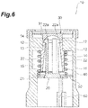
- Fig. 6 is a sectional view illustrating a state where claw parts illustrated in Fig. 5 are fixed.
- a housing 11 of the applicator 10 has a cylindrical shape.
- the shape of the housing may be changed or a housing surface may be processed in consideration of ease of holding the housing, and easiness of applying micro projections (microneedles) to a skin.
- a tubular housing having a polygonal cross-section shape may be used, an outer wall may be rounded as a whole, or recesses or steps may be provided to a cylindrical housing. Fine grooves may be formed on or coating may be applied on a surface of the housing in order to prevent slipping.
- the piston 20 for making an impact on a microneedle array put on a skin is stored in the vicinity of one end of the housing 11 (see Fig.2 ).
- the cap 30 for activating the piston 20 is stored in the vicinity of the other end of the housing 11 (see Fig. 1 ).
- the side where the cap 30 is stored is defined as the upper side of the applicator 10 or the housing 11
- the side where the piston 20 is stored is defined as the lower side of the applicator 10 or the housing 11.
- An annular member 11a is fitted into the upper end of the housing 11, and the lower end of the housing 11 is formed in a tapered shape expanding toward its downside.
- the piston 20 is a transmission member that includes a disk-shaped piston plate 21 colliding with the microneedle array, and a plurality of piston rods 22 as illustrated in Fig. 3 .
- the piston rods 22 extend from the vicinity of the center of the upper surface of the piston plate 21 in the direction orthogonal to the upper surface thereof.
- a plurality of air holes 21a for releasing air are provided to the piston plate 21, thereby reducing air resistance and reducing the weight of the piston 20.
- Hook-shaped claw parts 22a projecting outside in a diameter direction of the piston plate 21 each are provided to the tip ends of the respective piston rods 22.
- the claw parts 22a are formed in a tapered shape narrowing toward the tip ends of the piston rods 22.
- the shape of the cap 30 is disk-shaped as illustrated in Fig. 4 , and its diameter is substantially the same as the inner diameter of the housing 11.
- a cylindrical projection part 31 is provided on the center of the lower surface of the cap 30, and a recessed part 32 is provided to the projection part 31.
- a shape of the recessed part 32 is conical so as to receive the claw parts 22a of the piston rods 22.
- a partition wall 12 for partitioning the inside of the housing 11 into the upper side part and the lower side part is provided in the vicinity of the upper part inside the housing 11 as illustrated in Fig. 5 .
- a space over the partition wall 12 is referred to as an upper part space 14, whereas a space thereunder is referred to as a lower part space 15.
- the center of the partition wall 12 has a round through hole 13.
- An inner cylinder 16 is attached to the through hole 13 in a state of being inserted from under the through hole 13 to the middle thereof.
- the inner wall of the inner cylinder 16 is formed in a tapered shape expanding toward its downside, and serves for guiding vertical motion of the piston rods 22.
- the upper part of the through hole 13 serves for guiding the projection part 31 of the cap 30, and the diameter of the upper part is the same as that of the projection part 31.
- the upper end of the inner cylinder 16 positioned in the vicinity of the center of the through hole 13 serves for fixing the piston 20, being engaged with the claw parts 22a of the piston rods 22.
- the upper end of the inner cylinder 16 is referred to as a claw receiving part 17.
- the lower part space 15 stores the piston 20, a compression spring (biasing member or elastic member; hereinafter, simply referred to as "spring") 40 providing biasing force to the piston 20, and an annular spring base (support base) 50 supporting the spring 40 from under thereof.
- a plurality of guides 60 for sliding the spring base 50 within a predetermined range in the vertical direction are provided on the inner wall of the lower part space 15.
- Each of the guides 60 extends from the lower end of the housing 11 to the vicinity of the lower end of the inner cylinder 16, and a substantially lower half area of each guide 60 (lower part of the guide 60) is wider than the remaining upper half area (upper part of the guide 60).
- Notches (not illustrated) for engaging with the upper part of the guides 60 are provided on the outer periphery of the spring base 50. This structure allows the spring base 50 to slide within the upper part of the guides 60 in the vertical direction.
- the spring 40 is stored in the lower part space 15 so as to surround the inner cylinder 16.
- the upper end of the spring 40 is attached to the lower surface of the partition wall 12, whereas the lower end thereof is in contact with the upper surface of the spring base 50.
- a column coil spring may be used as the spring 40 as illustrated in Fig. 5 .
- the piston 20 is stored in the lower part space 15 after the spring 40 and the spring base 50 are stored in the lower part space 15.
- the diameter of the piston plate 21 is substantially the same as the inner diameter of the housing 11 limited by the lower part of the guides 60.
- the diameter of the piston plate 21 is larger than the inner diameter of the spring base 50, and the piston plate 21 is always positioned lower than the spring base 50.
- the piston 20 can be fixed in a state of resisting the biasing force of the spring 40 in the lower part space 15.
- the claw parts 22a of the respective piston rods 22 pass through the inner cylinder 16, and are hooked to the claw receiving part 17 as illustrated in Fig. 6 . This allows the piston 20 to be fixed in a state of resisting the biasing force of the spring 40.
- the cap 30 is stored in the upper part space 14 with the projection part 31 facing the partition wall 12.
- the annular member 11a is attached to an end part thereof. This can prevent the cap 30 from jumping out of the housing 11.
- the position of the cap 30 is not fixed in the upper part space 14, and the cap 30 can freely move along an extending direction (vertical direction) of the housing 11 in the upper part space 14.
- the applicator 10 is inclined so that the cap 30 is positioned higher than the piston 20, which is fixed in a state of resisting the biasing force of the spring 40, the projection part 31 of the cap 30 is in contact with the claw parts 22a of the piston 20 as illustrated in Fig. 6 .
- the cap 30 is provided freely movable along the extending direction of the housing 11 in the upper part space 14 so that the projection part 31 can be in contact with the claw parts 22a when the piston 20 is fixed by the claw parts 22a.
- Examples of parameters related to energy of the piston 20 activated by the biasing force of the spring 40 include a transverse elasticity modulus, a wire diameter, the number of windings, an average coil diameter, a distance indicating how long the spring 40 is shortened from its natural length, the speed of the piston, the mass of the spring, and the mass of the piston.
- the transverse elasticity modulus is determined by a material of the spring, and is 68500 N/mm 2 when the material is stainless and is 78500 N/mm 2 when the material is a piano wire (steel).
- Estimated values of the other parameters are as follows.
- the wire diameter is from 0.1 to 5 mm
- the number of windings is from 1 to 20
- the average coil diameter is from 1 to 30 mm
- the distance is from 1 to 100 mm
- the speed is from 0.1 to 50 m/s
- the mass of the spring is from 0.1 to 5 g
- the mass of the piston is from 0.1 to 20 g.
- the mass of the piston is 1.5 g or less.
- Equation (1) indicates a relation between the spring constant, the shape of the spring, and the material
- Equation (2) indicates a relation between the mass and the size of the spring
- Equation (3) indicates a relation between the spring energy and the kinetic energy
- Equation (4) indicates a relation between the speed, the energy, and the mass of the piston.
- G indicates the transverse elasticity modulus (N/m 2 ); “d” indicates the wire diameter (m); “n” indicates the number of windings; “D” indicates the average coil diameter (m); “k” indicates the spring constant (N/m); “x” indicates the distance (m); “v” indicates the speed (m/s); “1” indicates the length of the spring in its extension (m); “ ⁇ ” indicates the density (kg/m 3 ); “m” indicates the mass of the spring (kg); and “M” indicates the mass of the piston (kg).
- the kinetic energy is considered to be the same as energy (puncture energy) when the micro projections (microneedles) puncture skin.
- the size of the applicator 10 can be determined depending on the size of the microneedle array below, however, how to determine the size is not limited to as follows.
- the size of the applicator 10 can be reduced depending on the size of the microneedle array. If the lower side opening part is formed in this manner, the applicator 10 is not shifted to the diameter direction (width direction) against the microneedle array when positioned on the microneedle array.
- the applicator 10, thus, enables the piston 20 to be applied to the microneedle array while keeping a positional relation parallel to the microneedle array. This allows puncture to be surely performed (improves the reproducibility of puncture).
- a material of the applicator is not limited, but is preferably the one that has strength capable of keeping the biasing force of the spring 40.
- Examples of the material are as follows.
- Examples of the material of the housing 11 or the cap 30 can include a synthetic resin material such as acrylonitrile-butadiene-styrene (ABS) resin, polystyrene, polypropylene, and polyacetal (POM), a natural resin material, silicon, silicon dioxide, ceramic, and metal (such as stainless, titanium, nickel, molybdenum, chromium, and cobalt).
- ABS acrylonitrile-butadiene-styrene
- POM polyacetal
- the piston 20 may be produced using the same material as that of the microneedle array.
- Air holes may be provided to the housing 11 and the cap 30 similarly to the piston plate 21. This can reduce air resistance of the cap 30 and reduce the weight of the applicator 10.
- Fig. 7 is a perspective view illustrating the microneedle array 90.
- the microneedle array 90 includes a substrate 91 and a plurality of micro projections (needles, in other words, microneedles) 92 two-dimensionally arranged on the substrate 91.
- the substrate 91 is a base for supporting the micro projections 92.
- Fig. 7 illustrates the rectangular substrate 91, but the shape of the substrate 91 is not limited to this and may be round, for example.
- the micro projections 92 are arranged in zigzag (alternately) at substantially equal intervals on a surface of the substrate 91.
- a plurality of through holes may be provided to the substrate 91 so as to administer bioactive agents from the back side of the substrate 91 through the through holes.
- the area of the substrate 91 may be from 0.5 cm 2 to 10 cm 2 , from 1 cm 2 to 5 cm 2 , or from 1 cm 2 to 3 cm 2 .
- Several substrates 91 may be connected so as to obtain a substrate of a desired size.
- Each of the micro projections 92 is a tapered structure narrowing from its bottom part connected to the substrate 91 toward its tip. The tip ends of the respective micro projections may be sharpened or unsharpened.
- Fig. 7 illustrates the conical micro projections 92, but micro projections having a polygonal pyramid shape such as a square pyramid may be used. The height (length) of the micro projections 92 may be from 20 to 400 ⁇ m or from 50 to 300 ⁇ m.
- micro projections 92 are provided in one column.
- An interval between adjacent columns is substantially equal to an interval between adjacent micro projections 92 in one column.
- the density (needle density) of the micro projections 92 thus, may be, by way of an example not forming part of the present invention, from 100 to 10000 needles/cm 2 .
- the lower limit of the needle density is 500 needles/cm 2 .
- the upper limit of the needle density may be 5000 needles/cm 2 , 2000 needles/cm 2 , or 850 needles/cm 2 .
- Coating of the active agents is applied on the substrate 91 and/or the micro projections 92.
- the coating is the one in which a coating liquid including the active agent is fixed on a part or the whole of the micro projections 92 and/or the substrate 91.
- a term "fixed" means to keep a state where an object is approximately uniformly coated with the coating liquid.
- the coating is applied in a prescribed range including the top of the micro projections 92. This range varies depending on the height of the micro projections 92, and may be from 0 to 500 ⁇ m, from 10 to 500 ⁇ m, or from 30 to 300 ⁇ m.
- the thickness of the coating may be less than 50 ⁇ m, less than 25 ⁇ m, or from 1 to 10 ⁇ m.
- the thickness of the coating is an average thickness measured over the surface of the micro projections 92 after drying.
- the thickness of the coating can be increased by applying a plurality of films of a coating carrier, in other words, by repeating a coating process after the coating carrier is
- Fig. 8 is a view illustrating a case where an auxiliary tool H is employed in use of the applicator 10.
- Fig. 9 is a view illustrating how to use the applicator 10.
- the initial state of the applicator 10 is as illustrated in Fig. 5 .
- the piston 20 in an initial state is pushed inside the applicator 10 by a finger, and the piston 20 is fixed in a state of resisting the biasing force of the spring 40.
- the piston 20 may be pushed up by a hand or may be pushed up by the auxiliary tool H as illustrated in Fig. 8 .
- the shape of the auxiliary tool H is not limited to an example in Fig. 8 .
- the applicator 10 in which the piston 20 is fixed becomes a state illustrated in Fig. 6 .
- the inner wall of the inner cylinder 16 is formed in a tapered shape narrowing toward the upper end (claw receiving part 17).
- the force to be applied when the piston 20 is fixed can be strengthened or weakened by adjusting an inclination of the tapered shape of the inner cylinder 16.
- the applicator 10 is positioned and kept on the microneedle array 90 put on a skin S, and the cap 30 is pushed inside the applicator 10 by a finger (is pushed in an arrow A direction) as illustrated in Fig. 9 .
- the microneedle array 90 may be attached to the skin with a cover agent C before the applicator 10 is positioned as illustrated in Fig. 9 .
- the projection part 31 provided to its lower surface pushes the claw parts 22a of the respective piston rods 22 toward the center of the through hole 13, so that the engagement between the claw parts 22a and the claw receiving part 17 is released.
- the spring base 50 slides within the upper part of the guides 60.
- the piston 20 receives the biasing force of the spring 40 (the piston 20 is pushed in the second section by the spring base 50) within a section along the upper part of the guides 60 (second section) through the spring base 50 to move.
- the piston 20 moves in a section along the lower part of the guides 60 (first section) without receiving the biasing force of the spring 40 and collides with the microneedle array 90 at the lower end of the applicator 10 (see Fig. 9 ).
- the projection part 31 is a release mechanism for releasing the piston 20 fixed in a state of resisting the biasing force of the spring 40. Since the conical recessed part 32 is provided to the projection part 31, the claw parts 22a is drawn along the conical shape and the piston 20 (applicator 10) is activated only when a certain force is applied to the cap 30. Thus, a constant impact is made if anyone carries out administration. This allows puncture to be surely performed (improves the reproducibility of puncture).
- a force necessary for releasing the piston 20 can be adjusted by changing the shape of the recessed part 32 and the shape of the claw parts 22a. For example, if the inclination of the tapered shape of the claw parts 22a is made steep and the inclination of the conical shape of the recessed part 32 is adjusted corresponding thereto, the piston 20 can be released from the fixed state by a small force.
- the collision transmits an biasing force of the spring 40 to the microneedle array 90 through the piston 20, whereby the micro projections 92 puncture the skin.
- the active agents applied on the microneedle array 90 are administered to a body through the micro projections 92.
- the piston 20 can be fixed again in a state of resisting the biasing force of the spring 40 by being pushed inside the applicator 10.
- the applicator 10, thus, can be used repeatedly.
- the piston 20 transmitting biasing force necessary for puncture to the microneedle array 90 is very light, and the user feels less impact during operation of the applicator 10. The user, therefore, can administer the active agent using the applicator 10 without fear. In addition, even if the piston 20 is lightened in order not to give fear to the user, the active agent can be effectively administered by properly setting the momentum of the piston 20 and the needle density of the micro projections 92.
- Puncture performance was evaluated using the applicator and the microneedle array described in the embodiment.
- the spring included in the applicator was a column coil spring that was approximately 20 mm in length in an extending state (the height of the spring in an extending state is referred to "free height") and was approximately 10 mm in length in a compressed state.
- the puncture performance was evaluated by administering ovalbumin (OVA) to a human skin (in vitro) with the microneedle array so as to obtain the transfer amount of OVA to the human skin.
- OVA ovalbumin
- the transfer amount means an amount that is administered to the skin out of OVA fixed on the micro projections.
- the momentum P of the piston is an index for puncture energy when the micro projections (microneedles) collide with the human skin.
- microneedle arrays there were prepared three types of polylactic acid microneedle arrays (array A, array B, and array C).
- the height of the micro projection was 500 ⁇ m
- the area of the flat part at its tip was from 64 to 144 ⁇ m 2 .
- the coating range was approximately 180 ⁇ m including the top of the micro projections when OVA was applied on the respective micro projections.
- the differences among three types of microneedle arrays are the number of micro projections, the area of the substrate, the needle density, and an initial content (total amount) of OVA. Specific values are as shown in Table 1.
- OVA OVA was administered to the human skin by activating the applicator to make the piston plate collide with the microneedle array.
- the microneedle array removed from the human skin after the administration of OVA was soaked in phosphate buffered saline (PBS) so as to extract OVA.
- PBS phosphate buffered saline
- the amount of the extracted OVA was subtracted from the initial applied amount so as to obtain the transfer amount and the transfer rate.
- the speed of the activated piston was measured by a laser displacement gauge called LK-H150, which was made by Keyence corporation. Results shown in Figs. 10 and 11 were obtained by applying this experiment to various combinations of the piston, the spring, and the microneedle array.
- a graph in Fig. 10 illustrates transfer rates of OVA in relation with momentums of the pistons.
- the transfer rate of OVA was obtained by variously changing the combination of the piston and the spring in the microneedle array (i.e., array A) having the substrate area of 1.13 cm 2 and 640 micro projections.
- an area P surrounded by a dashed line shows the preferred transfer rate.
- This area P corresponds approximately to a case where the mass of the piston is 1.5 g or less and the momentum of the piston is from 0.0083 (N ⁇ s) to 0.015 (N ⁇ s).
- a graph in Fig. 11 illustrates transfer rates of OVA in relation with kinetic energy density.
- the transfer rate of OVA was obtained by variously changing the combination of the piston and the spring in the microneedle array having the substrate area of 1.13 cm 2 and 640 micro projections (i.e., array A).
- the abscissa in Fig. 10 is replaced with the kinetic energy density. It was predicted that the transfer rate and the kinetic energy density correspond to each other by one to one (that is, they indicate a proportional relation and have data plotted on the almost same straight line).
- the transfer rate may be different depending on the mass and the speed of the piston as illustrated in Fig. 11 . Specifically, it has been found that the higher transfer rate can be obtained when a light piston collides with the microneedle array at high speed, compared with a case when a heavy piston collides with the microneedle array at low speed.
- a graph in Fig. 12 illustrates transfer amounts of OVA obtained by changing microneedle arrays and springs against a piston having a mass of 1.1906 g. This graph shows that the transfer amount is preferable when the needle density was 500 needles/cm 2 or more (when the array A or array C was used). It has been also found that, when the needle density is 500 needles/cm 2 or more, the transfer amount is proportional to the momentum of the piston.
- the piston 20 moves toward the microneedle array without receiving the biasing force of the spring 40 in a part of the movement section, but the piston may keep receiving biasing force in the whole movement section (in other words, all during operation).
- the present invention can be applied to an applicator 100 in which the lower end of a spring (biasing member) 140 is in contact with the upper surface of a piston plate 121 as illustrated in Fig. 13 .
- a cap 130 is pushed in the same manner as the case of the applicator 10 so as to activate a piston (transmission member) 120, whereby the piston 120 is continuously pushed by the spring 140 until the piston 120 reaches the lower end of the applicator 100.
- the present invention can be applied to an applicator 200 illustrated in Figs. 14 and 15 .
- the applicator 200 includes a main body 211 and a cap 230.
- the main body 211 stores a piston 220 transmitting the biasing force of a spring 240 to the microneedle array.
- the piston 220 includes a rod-like member 222 activated by the spring 240 and a transmission plate (transmission member) 221 provided to the lower end part of the rod-like member 222.
- the transmission plate 221 is not fixed to but hooked to the rod-like member 222 in a state of imparting a shaft directional play of the rod-like member 222.
- the spring is used as the biasing member in the embodiment, but the biasing member is not limited to this.
- a mechanism in which a jet of compressed gas causes the piston to collide with the microneedle array may be adopted as the biasing member.
- microneedle array 90 and the applicator 10 are independent in the embodiment, but the microneedle array 90 may be integrated with the applicator 10.
- the microneedle array 90 may be integrated with the surface of the piston plate 21 (surface opposite to the piston rods 22).
- Examples of integrating the microneedle array 90 with the piston plate 21 include a case in which the microneedle array 90 is bonded to the piston plate 21 by an adhesive or other means, a case in which the microneedle array 90 is mechanically fitted to the piston plate 21 by a claw member or other members,, and a case in which micro projections (microneedles) are directly formed on the piston plate 21 using integral forming or other methods.
Description
- The present invention relates to an applicator used for assisting administration of an active agent with microneedles.
- There has been conventionally known an applicator that makes an impact on a microneedle array administering an active agent through a skin so as to apply microneedles included in the microneedle array to the skin.
- For example, the following Patent Literature 1 discloses an applicator that includes a device body, a piston for impacting a penetrating member with a stratum corneum, an impact spring for providing an impact force to the piston, a hold down spring operating between the device body and a cap, and a lock mechanism for compressing the device body and the piston together with compressing force so as to cock and lock the piston in a cocked position.
- The following Patent Literature 2 discloses an applicator that includes a housing, a piston movable within the housing, and a cap.
- The following
Patent Literature 3 discloses an insertion device for applying an insertion head that includes an infusion cannula or a puncturing tip introduced into a body of a patient. The device includes two actuation members, which have to be actuated simultaneously to trigger the insertion movement. - The following Patent Literature 4 discloses a puncture device including a drive spring in which one end of the drive spring is not fixed to a housing side contact section or a piston.
-
US 2005/0096586 discloses an applicator for applying a micro projection member to the stratum corneum of the patient, having a housing, a piston movable within the housing and adapted to activate the applicator. A biased spring asserts a force on the piston which can be released by the cap to impact the micro projection member. -
US 2006/0142691 A1 describes an apparatus for piercing skin with microprotrusions. A piston receives an impact force by an impact spring and applies said force to a micro preacher prudent member. -
US 11/172639 A1 -
WO 2012/046816 A1 discloses an applicator for applying a microneedle to skin comprising a tube shaped housing, a piston for transmitting a pressing force of a spring to a microneedle and an affixation means for fixing the piston to the housing. A cap is provided in the vicinity of a first section of the housing, comprising a surface facing the piston, which is adapted to release the piston. -
- Patent Literature 1: Japanese Patent No.
4198985 - Patent Literature 2: Publication of Japanese Translation of
PCT Application No. 2007-509706 - Patent Literature 3: Publication of Japanese Translation of
PCT Application No. 2010-501211 - Patent Literature 4: Japanese Patent Application Laid-Open Publication No.
2010-233803 - Using the above-mentioned applicators, a user can effectively administer an active agent; however, such applicators make an impact of a prescribed level or more on a skin. This may cause the user to fear of application of microneedles using the applicators. Thus, it is requested that an active agent be effectively administered to the user without fear when applying the microneedles.
- The invention is defined solely by the appended claims 1-5. An applicator in accordance with one embodiment of the present invention is the one for applying microneedles to a skin, and includes a transmission member that transmits biasing force of a biasing member to a microneedle array including microneedles with a needle density of 500 needles/cm2 or more. A mass of the transmission member is 1.5 g or less, and a momentum of the transmission member activated by the biasing force of the biasing member is from 0.0083 (N·s) to 0.015 (N·s).
- In this embodiment, the transmission member transmitting the biasing force necessary for puncture to the microneedle array is very light, and the user feels less impact during operation of the applicator. The user, therefore, can administer the active agent using the applicator without fear. In addition, even if the transmission member is lightened in order not to give fear to the users, the active agent can be effectively administered by setting the momentum of the transmission member and the needle density of the microneedles as described above.
- In the applicator in accordance with another embodiment, a transfer amount of the active agent applied on the microneedles to a skin may be proportional to the momentum of the transmission member.
- In the applicator in accordance with still another embodiment, the biasing member may be an elastic member, and the transmission member may move without receiving the biasing force of the elastic member in a first section forming a part of a movement section in which the transmission member moves toward the skin.
- The applicator in accordance with still another embodiment may further include a support base that supports the elastic member and transmits the biasing force to the transmission member in a second section different form the first section. The support base pushed the transmission member with the biasing force stops at one end of the second section, the transmission member may move without receiving the biasing force in the first section.
- The biasing member of the applicator in accordance with still another embodiment may be a column coil spring.
- According to one aspect of the present invention, an active agent can be effectively administered to a user without fear when applying microneedles.
-
- [
Fig. 1] Fig. 1 is a perspective view illustrating an applicator in accordance with an embodiment from the upper part. - [
Fig. 2] Fig. 2 is a perspective view illustrating the applicator illustrated inFig. 1 from the lower part. - [
Fig. 3] Fig. 3 is a perspective view illustrating a piston illustrated inFig. 2 . - [
Fig. 4] Fig. 4 is a perspective view illustrating a cap illustrated inFig. 1 . - [
Fig. 5] Fig. 5 is a sectional view along line V-V ofFig. 2 . - [
Fig. 6] Fig. 6 is a sectional view illustrating a state where claw parts illustrated inFig. 5 are fixed. - [
Fig. 7] Fig. 7 is a perspective view illustrating a microneedle array. - [
Fig. 8] Fig. 8 is a view illustrating a case where an auxiliary tool is employed in use of the applicator illustrated inFig. 1 . - [
Fig. 9] Fig. 9 is a view illustrating how to use the applicator illustrated inFig. 1 . - [
Fig. 10] Fig. 10 is a graph illustrating relations between momentums of the pistons and transfer rates of ovalbumin (OVA) in accordance with an example. - [
Fig. 11] Fig. 11 is a graph illustrating relations between kinetic energy density of the pistons and transfer rates of OVA in accordance with the example. - [
Fig. 12] Fig. 12 is another graph illustrating a relation between momentums of the piston and transfer amounts of OVA in accordance with the example. - [
Fig. 13] Fig. 13(a) is a perspective view illustrating an applicator in accordance with a modified embodiment, andFig. 13(b) is a sectional view along line B-B ofFig. 13(a) . - [
Fig. 14] Fig. 14 is a perspective view illustrating an applicator in accordance with another modified embodiment. - [
Fig. 15] Fig. 15 is a sectional view along line XV-XV ofFig. 14 . - Embodiments according to the present invention will now be described in detail with reference to the accompanying drawings. In the explanation of the drawings, same or similar components are denoted by the same reference numerals, and an overlapping explanation thereof will be omitted.
- A structure of an
applicator 10 in accordance with the embodiment will be described first with reference toFigs. 1 to 6 .Fig. 1 is a perspective view illustrating theapplicator 10 from the upper part.Fig. 2 is a perspective view illustrating theapplicator 10 from the lower part.Fig. 3 is a perspective view illustrating apiston 20.Fig. 4 is a perspective view illustrating acap 30.Fig. 5 is a sectional view along line V-V ofFig. 2 , andFig. 6 is a sectional view illustrating a state where claw parts illustrated inFig. 5 are fixed. - A
housing 11 of theapplicator 10 has a cylindrical shape. In theapplicator 10, the shape of the housing may be changed or a housing surface may be processed in consideration of ease of holding the housing, and easiness of applying micro projections (microneedles) to a skin. For example, a tubular housing having a polygonal cross-section shape may be used, an outer wall may be rounded as a whole, or recesses or steps may be provided to a cylindrical housing. Fine grooves may be formed on or coating may be applied on a surface of the housing in order to prevent slipping. - The
piston 20 for making an impact on a microneedle array put on a skin is stored in the vicinity of one end of the housing 11 (seeFig.2 ). Thecap 30 for activating thepiston 20 is stored in the vicinity of the other end of the housing 11 (seeFig. 1 ). Hereinafter, the side where thecap 30 is stored is defined as the upper side of theapplicator 10 or thehousing 11, whereas the side where thepiston 20 is stored is defined as the lower side of theapplicator 10 or thehousing 11. Anannular member 11a is fitted into the upper end of thehousing 11, and the lower end of thehousing 11 is formed in a tapered shape expanding toward its downside. - The
piston 20 is a transmission member that includes a disk-shapedpiston plate 21 colliding with the microneedle array, and a plurality ofpiston rods 22 as illustrated inFig. 3 . Thepiston rods 22 extend from the vicinity of the center of the upper surface of thepiston plate 21 in the direction orthogonal to the upper surface thereof. A plurality ofair holes 21a for releasing air are provided to thepiston plate 21, thereby reducing air resistance and reducing the weight of thepiston 20. Hook-shapedclaw parts 22a projecting outside in a diameter direction of thepiston plate 21 each are provided to the tip ends of therespective piston rods 22. Theclaw parts 22a are formed in a tapered shape narrowing toward the tip ends of thepiston rods 22. - The shape of the
cap 30 is disk-shaped as illustrated inFig. 4 , and its diameter is substantially the same as the inner diameter of thehousing 11. Acylindrical projection part 31 is provided on the center of the lower surface of thecap 30, and a recessedpart 32 is provided to theprojection part 31. A shape of the recessedpart 32 is conical so as to receive theclaw parts 22a of thepiston rods 22. - A
partition wall 12 for partitioning the inside of thehousing 11 into the upper side part and the lower side part is provided in the vicinity of the upper part inside thehousing 11 as illustrated inFig. 5 . Hereinafter, a space over thepartition wall 12 is referred to as anupper part space 14, whereas a space thereunder is referred to as alower part space 15. The center of thepartition wall 12 has a round throughhole 13. Aninner cylinder 16 is attached to the throughhole 13 in a state of being inserted from under the throughhole 13 to the middle thereof. The inner wall of theinner cylinder 16 is formed in a tapered shape expanding toward its downside, and serves for guiding vertical motion of thepiston rods 22. - The upper part of the through
hole 13 serves for guiding theprojection part 31 of thecap 30, and the diameter of the upper part is the same as that of theprojection part 31. The upper end of theinner cylinder 16 positioned in the vicinity of the center of the throughhole 13 serves for fixing thepiston 20, being engaged with theclaw parts 22a of thepiston rods 22. Hereinafter, the upper end of theinner cylinder 16 is referred to as aclaw receiving part 17. - The
lower part space 15 stores thepiston 20, a compression spring (biasing member or elastic member; hereinafter, simply referred to as "spring") 40 providing biasing force to thepiston 20, and an annular spring base (support base) 50 supporting thespring 40 from under thereof. A plurality ofguides 60 for sliding thespring base 50 within a predetermined range in the vertical direction are provided on the inner wall of thelower part space 15. - Each of the
guides 60 extends from the lower end of thehousing 11 to the vicinity of the lower end of theinner cylinder 16, and a substantially lower half area of each guide 60 (lower part of the guide 60) is wider than the remaining upper half area (upper part of the guide 60). Notches (not illustrated) for engaging with the upper part of theguides 60 are provided on the outer periphery of thespring base 50. This structure allows thespring base 50 to slide within the upper part of theguides 60 in the vertical direction. Thespring 40 is stored in thelower part space 15 so as to surround theinner cylinder 16. The upper end of thespring 40 is attached to the lower surface of thepartition wall 12, whereas the lower end thereof is in contact with the upper surface of thespring base 50. In the embodiment, a column coil spring may be used as thespring 40 as illustrated inFig. 5 . - The
piston 20 is stored in thelower part space 15 after thespring 40 and thespring base 50 are stored in thelower part space 15. The diameter of thepiston plate 21 is substantially the same as the inner diameter of thehousing 11 limited by the lower part of theguides 60. The diameter of thepiston plate 21 is larger than the inner diameter of thespring base 50, and thepiston plate 21 is always positioned lower than thespring base 50. - The
piston 20 can be fixed in a state of resisting the biasing force of thespring 40 in thelower part space 15. When thepiston plate 21 is pushed from the outside of thehousing 11 against the biasing force of thespring 40 in an initial state of the applicator 10 (seeFig. 5 ), theclaw parts 22a of therespective piston rods 22 pass through theinner cylinder 16, and are hooked to theclaw receiving part 17 as illustrated inFig. 6 . This allows thepiston 20 to be fixed in a state of resisting the biasing force of thespring 40. - The
cap 30 is stored in theupper part space 14 with theprojection part 31 facing thepartition wall 12. When thewhole cap 30 is stored in this manner, theannular member 11a is attached to an end part thereof. This can prevent thecap 30 from jumping out of thehousing 11. - The position of the
cap 30 is not fixed in theupper part space 14, and thecap 30 can freely move along an extending direction (vertical direction) of thehousing 11 in theupper part space 14. When theapplicator 10 is inclined so that thecap 30 is positioned higher than thepiston 20, which is fixed in a state of resisting the biasing force of thespring 40, theprojection part 31 of thecap 30 is in contact with theclaw parts 22a of thepiston 20 as illustrated inFig. 6 . In other words, thecap 30 is provided freely movable along the extending direction of thehousing 11 in theupper part space 14 so that theprojection part 31 can be in contact with theclaw parts 22a when thepiston 20 is fixed by theclaw parts 22a. - Examples of parameters related to energy of the
piston 20 activated by the biasing force of thespring 40 include a transverse elasticity modulus, a wire diameter, the number of windings, an average coil diameter, a distance indicating how long thespring 40 is shortened from its natural length, the speed of the piston, the mass of the spring, and the mass of the piston. - The transverse elasticity modulus is determined by a material of the spring, and is 68500 N/mm2 when the material is stainless and is 78500 N/mm2 when the material is a piano wire (steel). Estimated values of the other parameters are as follows. The wire diameter is from 0.1 to 5 mm, the number of windings is from 1 to 20, the average coil diameter is from 1 to 30 mm, the distance is from 1 to 100 mm, the speed is from 0.1 to 50 m/s, the mass of the spring is from 0.1 to 5 g, and the mass of the piston is from 0.1 to 20 g. In the embodiment, the mass of the piston is 1.5 g or less.
- Theoretical formulae related to the spring and the piston are defined with the parameters below. Equation (1) indicates a relation between the spring constant, the shape of the spring, and the material; Equation (2) indicates a relation between the mass and the size of the spring; Equation (3) indicates a relation between the spring energy and the kinetic energy; and Equation (4) indicates a relation between the speed, the energy, and the mass of the piston. In the following formulae, "G" indicates the transverse elasticity modulus (N/m2); "d" indicates the wire diameter (m); "n" indicates the number of windings; "D" indicates the average coil diameter (m); "k" indicates the spring constant (N/m); "x" indicates the distance (m); "v" indicates the speed (m/s); "1" indicates the length of the spring in its extension (m); "ρ" indicates the density (kg/m3); "m" indicates the mass of the spring (kg); and "M" indicates the mass of the piston (kg). In the description, the kinetic energy is considered to be the same as energy (puncture energy) when the micro projections (microneedles) puncture skin.


- The size of the
applicator 10 can be determined depending on the size of the microneedle array below, however, how to determine the size is not limited to as follows. - When a lower side opening part of the
housing 11 is shaped to fit the shape of the microneedle array and the minimum inner diameter of the opening part is adjusted to fit the outer diameter of the microneedle array, the size of theapplicator 10 can be reduced depending on the size of the microneedle array. If the lower side opening part is formed in this manner, theapplicator 10 is not shifted to the diameter direction (width direction) against the microneedle array when positioned on the microneedle array. Theapplicator 10, thus, enables thepiston 20 to be applied to the microneedle array while keeping a positional relation parallel to the microneedle array. This allows puncture to be surely performed (improves the reproducibility of puncture). - A material of the applicator is not limited, but is preferably the one that has strength capable of keeping the biasing force of the
spring 40. Examples of the material are as follows. Examples of the material of thehousing 11 or thecap 30 can include a synthetic resin material such as acrylonitrile-butadiene-styrene (ABS) resin, polystyrene, polypropylene, and polyacetal (POM), a natural resin material, silicon, silicon dioxide, ceramic, and metal (such as stainless, titanium, nickel, molybdenum, chromium, and cobalt). Thepiston 20 may be produced using the same material as that of the microneedle array. - Air holes may be provided to the
housing 11 and thecap 30 similarly to thepiston plate 21. This can reduce air resistance of thecap 30 and reduce the weight of theapplicator 10. - The following describes the structure of a
microneedle array 90 used together with theapplicator 10 with reference toFig. 7. Fig. 7 is a perspective view illustrating themicroneedle array 90. - The
microneedle array 90 includes a substrate 91 and a plurality of micro projections (needles, in other words, microneedles) 92 two-dimensionally arranged on the substrate 91. - The substrate 91 is a base for supporting the micro projections 92.
Fig. 7 illustrates the rectangular substrate 91, but the shape of the substrate 91 is not limited to this and may be round, for example. The micro projections 92 are arranged in zigzag (alternately) at substantially equal intervals on a surface of the substrate 91. A plurality of through holes may be provided to the substrate 91 so as to administer bioactive agents from the back side of the substrate 91 through the through holes. The area of the substrate 91 may be from 0.5 cm2 to 10 cm2, from 1 cm2 to 5 cm2, or from 1 cm2 to 3 cm2. Several substrates 91 may be connected so as to obtain a substrate of a desired size. - Each of the micro projections 92 is a tapered structure narrowing from its bottom part connected to the substrate 91 toward its tip. The tip ends of the respective micro projections may be sharpened or unsharpened.
Fig. 7 illustrates the conical micro projections 92, but micro projections having a polygonal pyramid shape such as a square pyramid may be used. The height (length) of the micro projections 92 may be from 20 to 400 µm or from 50 to 300 µm. - One to ten micro projections 92 per 1 mm are provided in one column. An interval between adjacent columns is substantially equal to an interval between adjacent micro projections 92 in one column. The density (needle density) of the micro projections 92, thus, may be, by way of an example not forming part of the present invention, from 100 to 10000 needles/cm2. The lower limit of the needle density is 500 needles/cm2. The upper limit of the needle density may be 5000 needles/cm2, 2000 needles/cm2, or 850 needles/cm2.
- Coating of the active agents is applied on the substrate 91 and/or the micro projections 92. The coating is the one in which a coating liquid including the active agent is fixed on a part or the whole of the micro projections 92 and/or the substrate 91. A term "fixed" means to keep a state where an object is approximately uniformly coated with the coating liquid. The coating is applied in a prescribed range including the top of the micro projections 92. This range varies depending on the height of the micro projections 92, and may be from 0 to 500 µm, from 10 to 500 µm, or from 30 to 300 µm. The thickness of the coating may be less than 50 µm, less than 25 µm, or from 1 to 10 µm. The thickness of the coating is an average thickness measured over the surface of the micro projections 92 after drying. The thickness of the coating can be increased by applying a plurality of films of a coating carrier, in other words, by repeating a coating process after the coating carrier is fixed.
- The following describes how to use the
applicator 10 with reference toFigs. 8 and9 .Fig. 8 is a view illustrating a case where an auxiliary tool H is employed in use of theapplicator 10.Fig. 9 is a view illustrating how to use theapplicator 10. - The initial state of the
applicator 10 is as illustrated inFig. 5 . Thepiston 20 in an initial state is pushed inside theapplicator 10 by a finger, and thepiston 20 is fixed in a state of resisting the biasing force of thespring 40. Thepiston 20 may be pushed up by a hand or may be pushed up by the auxiliary tool H as illustrated inFig. 8 . The shape of the auxiliary tool H is not limited to an example inFig. 8 . Theapplicator 10 in which thepiston 20 is fixed becomes a state illustrated inFig. 6 . The inner wall of theinner cylinder 16 is formed in a tapered shape narrowing toward the upper end (claw receiving part 17). This allows the user to engage theclaw parts 22a with theclaw receiving part 17 by a less force and easily fix thepiston 20. The user can recognize the completion of fixing with a "clicking" sound. The force to be applied when thepiston 20 is fixed can be strengthened or weakened by adjusting an inclination of the tapered shape of theinner cylinder 16. - Subsequently, the
applicator 10 is positioned and kept on themicroneedle array 90 put on a skin S, and thecap 30 is pushed inside theapplicator 10 by a finger (is pushed in an arrow A direction) as illustrated inFig. 9 . Themicroneedle array 90 may be attached to the skin with a cover agent C before theapplicator 10 is positioned as illustrated inFig. 9 . - When the
cap 30 is pushed, theprojection part 31 provided to its lower surface pushes theclaw parts 22a of therespective piston rods 22 toward the center of the throughhole 13, so that the engagement between theclaw parts 22a and theclaw receiving part 17 is released. This causes the fixed state of thepiston 20 to be released and allows thepiston 20 to move toward the outside of theapplicator 10 with the biasing force of thespring 40. Thespring base 50 slides within the upper part of theguides 60. Thus, thepiston 20 receives the biasing force of the spring 40 (thepiston 20 is pushed in the second section by the spring base 50) within a section along the upper part of the guides 60 (second section) through thespring base 50 to move. After thespring base 50 stops at the lower end in the second section, thepiston 20 moves in a section along the lower part of the guides 60 (first section) without receiving the biasing force of thespring 40 and collides with themicroneedle array 90 at the lower end of the applicator 10 (seeFig. 9 ). - Thus, it is conceivable that the
projection part 31 is a release mechanism for releasing thepiston 20 fixed in a state of resisting the biasing force of thespring 40. Since the conical recessedpart 32 is provided to theprojection part 31, theclaw parts 22a is drawn along the conical shape and the piston 20 (applicator 10) is activated only when a certain force is applied to thecap 30. Thus, a constant impact is made if anyone carries out administration. This allows puncture to be surely performed (improves the reproducibility of puncture). - A force necessary for releasing the
piston 20 can be adjusted by changing the shape of the recessedpart 32 and the shape of theclaw parts 22a. For example, if the inclination of the tapered shape of theclaw parts 22a is made steep and the inclination of the conical shape of the recessedpart 32 is adjusted corresponding thereto, thepiston 20 can be released from the fixed state by a small force. - The collision transmits an biasing force of the
spring 40 to themicroneedle array 90 through thepiston 20, whereby the micro projections 92 puncture the skin. The active agents applied on themicroneedle array 90 are administered to a body through the micro projections 92. - After the use of the
applicator 10 in this manner, thepiston 20 can be fixed again in a state of resisting the biasing force of thespring 40 by being pushed inside theapplicator 10. Theapplicator 10, thus, can be used repeatedly. - As described above, in the embodiment, the
piston 20 transmitting biasing force necessary for puncture to themicroneedle array 90 is very light, and the user feels less impact during operation of theapplicator 10. The user, therefore, can administer the active agent using theapplicator 10 without fear. In addition, even if thepiston 20 is lightened in order not to give fear to the user, the active agent can be effectively administered by properly setting the momentum of thepiston 20 and the needle density of the micro projections 92. - The present invention will now be specifically described based on embodiments, but is not limited to them at all. The following embodiment shows some examples about the mass and the momentum of the piston and the needle density of the micro projections (microneedles).
- Puncture performance was evaluated using the applicator and the microneedle array described in the embodiment. The spring included in the applicator was a column coil spring that was approximately 20 mm in length in an extending state (the height of the spring in an extending state is referred to "free height") and was approximately 10 mm in length in a compressed state. The puncture performance was evaluated by administering ovalbumin (OVA) to a human skin (in vitro) with the microneedle array so as to obtain the transfer amount of OVA to the human skin. The transfer amount means an amount that is administered to the skin out of OVA fixed on the micro projections.
- There were prepared four types of pistons each having different mass as follows: 0.9802 g; 1.1906 g; 1.6509 g; and 2.8603 g. There were prepared a plurality of kinds of springs each having different spring constants in order to obtain various momentum P for the respective pistons. Herein, the momentum P (N·s) of the piston is represented by "P = mv", where "m" is the mass of the piston (kg) and "v" is the speed of the piston (m/s). The momentum P of the piston is an index for puncture energy when the micro projections (microneedles) collide with the human skin.
- There were prepared three types of polylactic acid microneedle arrays (array A, array B, and array C). In each of the microneedle arrays, the height of the micro projection was 500 µm, and the area of the flat part at its tip was from 64 to 144 µm2. In each of the microneedle arrays, the coating range was approximately 180 µm including the top of the micro projections when OVA was applied on the respective micro projections. The differences among three types of microneedle arrays are the number of micro projections, the area of the substrate, the needle density, and an initial content (total amount) of OVA. Specific values are as shown in Table 1.
Table 1 Array A Array B Array C Number of micro projections 640 640 1336 Area of substrate (cm2) 1.13 2.26 2.26 Needle density (needles/cm2) 566 283 591 Initial content (µg) 51 44 96 - After the microneedle array in a state where the micro projections were coated with OVA was left still on the human skin and the applicator was positioned against the microneedle array, OVA was administered to the human skin by activating the applicator to make the piston plate collide with the microneedle array. The microneedle array removed from the human skin after the administration of OVA was soaked in phosphate buffered saline (PBS) so as to extract OVA. The amount of the extracted OVA was subtracted from the initial applied amount so as to obtain the transfer amount and the transfer rate. The speed of the activated piston was measured by a laser displacement gauge called LK-H150, which was made by Keyence corporation. Results shown in
Figs. 10 and11 were obtained by applying this experiment to various combinations of the piston, the spring, and the microneedle array. - A graph in
Fig. 10 illustrates transfer rates of OVA in relation with momentums of the pistons. The transfer rate of OVA was obtained by variously changing the combination of the piston and the spring in the microneedle array (i.e., array A) having the substrate area of 1.13 cm2 and 640 micro projections. In this graph, an area P surrounded by a dashed line shows the preferred transfer rate. This area P corresponds approximately to a case where the mass of the piston is 1.5 g or less and the momentum of the piston is from 0.0083 (N·s) to 0.015 (N·s). - A graph in
Fig. 11 illustrates transfer rates of OVA in relation with kinetic energy density. The transfer rate of OVA was obtained by variously changing the combination of the piston and the spring in the microneedle array having the substrate area of 1.13 cm2 and 640 micro projections (i.e., array A). In other words, in the graph inFig. 11 , the abscissa inFig. 10 is replaced with the kinetic energy density. It was predicted that the transfer rate and the kinetic energy density correspond to each other by one to one (that is, they indicate a proportional relation and have data plotted on the almost same straight line). However, it has been found that, even if the kinetic energy density is the same, the transfer rate may be different depending on the mass and the speed of the piston as illustrated inFig. 11 . Specifically, it has been found that the higher transfer rate can be obtained when a light piston collides with the microneedle array at high speed, compared with a case when a heavy piston collides with the microneedle array at low speed. - A graph in
Fig. 12 illustrates transfer amounts of OVA obtained by changing microneedle arrays and springs against a piston having a mass of 1.1906 g. This graph shows that the transfer amount is preferable when the needle density was 500 needles/cm2 or more (when the array A or array C was used). It has been also found that, when the needle density is 500 needles/cm2 or more, the transfer amount is proportional to the momentum of the piston. - The present invention has been described in detail based on the embodiment thereof, but it should be noted that the present invention is not limited to the embodiment. Various changes and modifications can be made without departing from the scope of the present invention.
- In the embodiment, the
piston 20 moves toward the microneedle array without receiving the biasing force of thespring 40 in a part of the movement section, but the piston may keep receiving biasing force in the whole movement section (in other words, all during operation). For example, the present invention can be applied to anapplicator 100 in which the lower end of a spring (biasing member) 140 is in contact with the upper surface of apiston plate 121 as illustrated inFig. 13 . In this case, acap 130 is pushed in the same manner as the case of theapplicator 10 so as to activate a piston (transmission member) 120, whereby thepiston 120 is continuously pushed by thespring 140 until thepiston 120 reaches the lower end of theapplicator 100. - The present invention can be applied to an
applicator 200 illustrated inFigs. 14 and15 . Theapplicator 200 includes amain body 211 and acap 230. Themain body 211 stores apiston 220 transmitting the biasing force of aspring 240 to the microneedle array. Thepiston 220 includes a rod-like member 222 activated by thespring 240 and a transmission plate (transmission member) 221 provided to the lower end part of the rod-like member 222. Thetransmission plate 221 is not fixed to but hooked to the rod-like member 222 in a state of imparting a shaft directional play of the rod-like member 222. When thepiston 220 is activated by the spring (biasing member) 240, first the rod-like member 222 and thetransmission plate 221 integrally move downward. Then, thetransmission plate 221 continuously drops to the lower end of theapplicator 200 and transmits the biasing force of thespring 240 to the microneedle array, whereas the lower end of the rod-like member 222 stops above the lower end of theapplicator 200. For details on theapplicator 200, refer to the description of Japanese Patent Application No.2011-164723 - The spring is used as the biasing member in the embodiment, but the biasing member is not limited to this. For example, a mechanism in which a jet of compressed gas causes the piston to collide with the microneedle array may be adopted as the biasing member.
- The
microneedle array 90 and theapplicator 10 are independent in the embodiment, but themicroneedle array 90 may be integrated with theapplicator 10. Specifically, themicroneedle array 90 may be integrated with the surface of the piston plate 21 (surface opposite to the piston rods 22). Examples of integrating themicroneedle array 90 with thepiston plate 21 include a case in which themicroneedle array 90 is bonded to thepiston plate 21 by an adhesive or other means, a case in which themicroneedle array 90 is mechanically fitted to thepiston plate 21 by a claw member or other members,, and a case in which micro projections (microneedles) are directly formed on thepiston plate 21 using integral forming or other methods. - 10... applicator, 11... housing, 20... piston, 30... cap, 40... spring, 90... microneedle array, 92... micro projections (microneedles), 100... applicator, 120... piston, 130... cap, 140... spring, 200... applicator, 220... piston, 230... cap, 240... spring.
Claims (5)
- An applicator (10, 100 200) applying microneedles to a skin, the applicator (10, 100, 200) comprising:a transmission member (20, 120, 220) that transmits biasing force of a biasing member (40, 140, 240) to a microneedle array (90) including microneedlescharacterized in thatthe microneedles (92) have a needle density of 500 needles/cm2 or more,a mass of the transmission member (20, 120, 220) is 1.5 g or less, anda momentum of the transmission member (20, 120, 220) activated by the biasing force of the biasing member (40, 140, 240) is from 0.0083 (N·s) to 0.015 (N·s).
- The applicator (10, 100, 200) according to claim 1, wherein a transfer amount of an active agent applied on the microneedles (92) to the skin is proportional to the momentum of the transmission member (20, 120, 220).
- The applicator (10, 100, 200) according to claim 1 or 2, wherein
the biasing member (40, 140, 240) is an elastic member, and
the transmission member (20, 120, 220) moves without receiving the biasing force of the elastic member (40, 140, 240) in a first section (60) forming a part of a movement section in which the transmission member (20, 120, 220) moves toward the skin. - The applicator (10, 100, 200) according to claim 3, further comprising a support base (50) that supports the elastic member (40, 140, 240) and transmits the biasing force to the transmission member (20, 120, 220) in a second section different form the first section (60), wherein
the support base (50) pushing the transmission member (20, 120, 220) with the biasing force stops at one end of the second section, whereby the transmission member (20, 120, 220) moves without receiving the biasing force in the first section (60). - The applicator (10, 100, 200) according to any one of claims 1 to 4, wherein the biasing member (40, 140, 240) is a column coil spring.
Applications Claiming Priority (2)
| Application Number | Priority Date | Filing Date | Title |
|---|---|---|---|
| JP2011222236 | 2011-10-06 | ||
| PCT/JP2012/075534 WO2013051568A1 (en) | 2011-10-06 | 2012-10-02 | Applicator |
Publications (3)
| Publication Number | Publication Date |
|---|---|
| EP2764887A1 EP2764887A1 (en) | 2014-08-13 |
| EP2764887A4 EP2764887A4 (en) | 2015-12-09 |
| EP2764887B1 true EP2764887B1 (en) | 2020-12-02 |
Family
ID=48043725
Family Applications (1)
| Application Number | Title | Priority Date | Filing Date |
|---|---|---|---|
| EP12838997.0A Active EP2764887B1 (en) | 2011-10-06 | 2012-10-02 | Applicator |
Country Status (5)
| Country | Link |
|---|---|
| US (1) | US9498611B2 (en) |
| EP (1) | EP2764887B1 (en) |
| JP (1) | JP6265740B2 (en) |
| TW (1) | TW201330893A (en) |
| WO (1) | WO2013051568A1 (en) |
Families Citing this family (25)
| Publication number | Priority date | Publication date | Assignee | Title |
|---|---|---|---|---|
| GB0402131D0 (en) | 2004-01-30 | 2004-03-03 | Isis Innovation | Delivery method |
| EP2231257A4 (en) | 2007-12-24 | 2013-11-06 | Univ Queensland | Coating method |
| US9943673B2 (en) | 2010-07-14 | 2018-04-17 | Vaxxas Pty Limited | Patch applying apparatus |
| WO2013053022A1 (en) | 2011-10-12 | 2013-04-18 | The University Of Queensland | Delivery device |
| JP6226862B2 (en) * | 2012-04-05 | 2017-11-08 | 久光製薬株式会社 | Puncture device and manufacturing method thereof |
| EP2937111B1 (en) | 2012-12-21 | 2020-03-18 | Hisamitsu Pharmaceutical Co., Inc. | Applicator |
| SG11201509722PA (en) * | 2013-05-31 | 2015-12-30 | 3M Innovative Properties Co | Microneedle injection apparatus comprising a dual cover |
| BR112016002695B1 (en) * | 2013-08-09 | 2022-09-20 | Cytrellis Biosystems, Inc | DEVICE WITH AN ABLATIVE DEVICE, A REMOVAL DEVICE AND A POSITIONING DEVICE |
| CA2924447C (en) * | 2013-09-18 | 2020-08-04 | Cosmed Pharmaceutical Co., Ltd. | Microneedle patch application device and patch holder |
| EP3067088B1 (en) | 2013-11-05 | 2019-09-04 | Hisamitsu Pharmaceutical Co., Inc. | Applicator |
| WO2016077759A1 (en) | 2014-11-14 | 2016-05-19 | Cytrellis Biosystems, Inc. | Devices and methods for ablation of the skin |
| CA2975275C (en) | 2015-02-02 | 2023-08-29 | Vaxxas Pty Limited | Microprojection array applicator and method |
| JP2017023404A (en) * | 2015-07-22 | 2017-02-02 | 日本写真印刷株式会社 | Impact-application-type applicator for microneedle patch and tip member |
| WO2017038499A1 (en) * | 2015-09-02 | 2017-03-09 | 久光製薬株式会社 | Applicator |
| WO2017045031A1 (en) | 2015-09-18 | 2017-03-23 | Vaxxas Pty Limited | Microprojection arrays with microprojections having large surface area profiles |
| US20180264244A1 (en) * | 2015-09-28 | 2018-09-20 | Vaxxas Pty Limited | Microprojection arrays with enhanced skin penetrating properties and methods thereof |
| EP4306803A3 (en) | 2017-03-31 | 2024-04-10 | Vaxxas Pty Limited | Device and method for coating surfaces |
| US11175128B2 (en) | 2017-06-13 | 2021-11-16 | Vaxxas Pty Limited | Quality control of substrate coatings |
| AU2018309562A1 (en) | 2017-08-04 | 2020-02-20 | Vaxxas Pty Limited | Compact high mechanical energy storage and low trigger force actuator for the delivery of microprojection array patches (MAP) |
| US10945759B2 (en) | 2017-12-28 | 2021-03-16 | Refine Usa, Llc | Microneedle device |
| JP7099189B2 (en) * | 2018-08-30 | 2022-07-12 | ニプロ株式会社 | Microneedle applicator |
| JP7172293B2 (en) * | 2018-08-30 | 2022-11-16 | ニプロ株式会社 | microneedle applicator |
| WO2020045588A1 (en) * | 2018-08-30 | 2020-03-05 | ニプロ株式会社 | Microneedle applicator |
| DE102019200557A1 (en) * | 2019-01-17 | 2020-07-23 | Lts Lohmann Therapie-Systeme Ag | Applicator |
| USD1023303S1 (en) * | 2021-12-08 | 2024-04-16 | Guangzhou Ekai Electronic Technology Co., Ltd. | Microneedling pen |
Family Cites Families (57)
| Publication number | Priority date | Publication date | Assignee | Title |
|---|---|---|---|---|
| US1033099A (en) | 1911-12-11 | 1912-07-23 | John W Harrison | Drill-socket. |
| US2932277A (en) | 1957-10-28 | 1960-04-12 | John E Borah | Moistening device |
| US4526171A (en) | 1980-01-15 | 1985-07-02 | Schachar Ronald A | Cornea incision device |
| US4589412A (en) | 1984-01-03 | 1986-05-20 | Intravascular Surgical Instruments, Inc. | Method and apparatus for surgically removing remote deposits |
| US4747842A (en) | 1987-06-22 | 1988-05-31 | David Dietz | Article for applying styptic to a dog's bleeding nail |
| US5026388A (en) | 1989-09-26 | 1991-06-25 | Ingalz Thomas J | Single-use skin puncture device |
| JP2954359B2 (en) | 1996-05-18 | 1999-09-27 | キム,ジン,サプ | Artemisia moxibustion device |
| GB9817662D0 (en) | 1998-08-13 | 1998-10-07 | Crocker Peter J | Substance delivery |
| US6743211B1 (en) | 1999-11-23 | 2004-06-01 | Georgia Tech Research Corporation | Devices and methods for enhanced microneedle penetration of biological barriers |
| CA2394171A1 (en) * | 1999-12-16 | 2001-06-21 | Alza Corporation | Device for enhancing transdermal flux of sampled agents |
| KR200209938Y1 (en) | 2000-07-25 | 2001-01-15 | 변영광 | Cosmetics case |
| JP4198985B2 (en) | 2000-10-13 | 2008-12-17 | アルザ・コーポレーシヨン | Microblade array impact applicator. |
| US7419481B2 (en) * | 2000-10-13 | 2008-09-02 | Alza Corporation | Apparatus and method for piercing skin with microprotrusions |
| MXPA03003303A (en) | 2000-10-13 | 2004-12-13 | Johnson & Johnson | Microprotrusion member retainer for impact applicator. |
| CN1250171C (en) * | 2000-10-13 | 2006-04-12 | 阿尔扎公司 | Apparatus and method for piercing skin with microtrusions |
| US6945952B2 (en) | 2002-06-25 | 2005-09-20 | Theraject, Inc. | Solid solution perforator for drug delivery and other applications |
| WO2004000389A2 (en) | 2002-06-25 | 2003-12-31 | Sung-Yun Kwon | Rapidly dissolving micro-perforator for drug delivery and other applications |
| KR20120087197A (en) | 2002-07-19 | 2012-08-06 | 쓰리엠 이노베이티브 프로퍼티즈 컴파니 | Microneedle device, method of using microneedle device and method of delivering microneedle device |
| JP4682144B2 (en) | 2003-10-31 | 2011-05-11 | アルザ・コーポレーシヨン | Self-actuating applicator for microprojection arrays |
| EP1706171A1 (en) | 2003-12-29 | 2006-10-04 | 3M Innovative Properties Company | Medical devices and kits including same |
| WO2005075016A1 (en) | 2004-02-03 | 2005-08-18 | Hisamitsu Pharmaceutical Co., Inc. | Interface for transdermal medicine applicator |
| WO2005123173A1 (en) | 2004-06-10 | 2005-12-29 | 3M Innovative Properties Company | Patch application device and kit |
| JPWO2006016647A1 (en) | 2004-08-12 | 2008-05-01 | 久光製薬株式会社 | Transdermal drug administration device with microneedle |
| JP2008520367A (en) | 2004-11-18 | 2008-06-19 | スリーエム イノベイティブ プロパティズ カンパニー | Non-skin-type microneedle array applicator |
| BRPI0517749A (en) | 2004-11-18 | 2008-10-21 | 3M Innovative Properties Co | application device for applying a micro-needle device to a skin surface, and method for using an application device |
| WO2006069053A2 (en) | 2004-12-22 | 2006-06-29 | Charm Sciences, Inc. | Sampling method and device |
| JP2006341089A (en) | 2005-05-13 | 2006-12-21 | Fujikura Ltd | Instrument for carrying medicinal material and manufacturing method of the same |
| WO2007015441A1 (en) | 2005-08-01 | 2007-02-08 | Hisamitsu Pharmaceutical Co., Inc. | Adjuvant or pharmaceutical preparation for transdermal or transmucosal administration |
| JP5000866B2 (en) | 2005-08-01 | 2012-08-15 | 久光製薬株式会社 | Non-toxic biopharmaceutical transport equipment |
| EP1992386B1 (en) | 2006-02-10 | 2011-11-09 | Hisamitsu Pharmaceutical Co., Inc. | Transdermal drug administration apparatus having microneedles |
| JP2009529400A (en) | 2006-03-10 | 2009-08-20 | アルザ コーポレイション | Application of microprojection array with high barrier holder |
| JP4963849B2 (en) | 2006-03-13 | 2012-06-27 | シスメックス株式会社 | Micropore formation system |
| JP4908893B2 (en) | 2006-03-30 | 2012-04-04 | 久光製薬株式会社 | Medicinal product carrying device, method for producing the same, and method for producing a mold for producing a medicinal product carrying device |
| JP5049268B2 (en) | 2006-04-07 | 2012-10-17 | 久光製薬株式会社 | Microneedle device and transdermal drug administration device with microneedle |
| US20070293816A1 (en) | 2006-04-25 | 2007-12-20 | Alza Corporation | Microprojection Array Application with Grouped Microprojections for High Drug Loading |
| DK2054109T3 (en) | 2006-08-24 | 2018-03-19 | Hoffmann La Roche | INTRODUCTION DEVICE FOR INTRODUCTION HEADS, ESPECIALLY FOR INFUSION KITS |
| WO2008091602A2 (en) | 2007-01-22 | 2008-07-31 | Corium International, Inc. | Applicators for microneedle arrays |
| US7381003B1 (en) | 2007-01-24 | 2008-06-03 | Chia-Sheng Chang | Applicator of cosmetic cream jar |
| EP2123296B1 (en) | 2007-01-31 | 2019-05-22 | Hisamitsu Pharmaceutical Co., Inc. | Adjuvant for transdermal or transmucosal administration and pharmaceutical preparation containing the same |
| WO2008096732A1 (en) | 2007-02-06 | 2008-08-14 | Hisamitsu Pharmaceutical Co., Inc. | Microneedle device for diagnosis of allergy |
| JP5298011B2 (en) | 2007-05-15 | 2013-09-25 | 久光製薬株式会社 | Microneedle coating method |
| US20100221314A1 (en) | 2007-10-18 | 2010-09-02 | Hisamitsu Pharmaceutical Co., Inc. | Microneedle Device |
| USD598173S1 (en) | 2008-06-13 | 2009-08-11 | Hartel David D | Tool for cleaning the outer surface of a tube |
| JPWO2010001671A1 (en) | 2008-06-30 | 2011-12-15 | 久光製薬株式会社 | Microneedle device and method for increasing the efficacy of influenza vaccine by microneedle device |
| USD612939S1 (en) | 2008-07-29 | 2010-03-30 | Envy Medical, Inc. | Microdermabrasion treatment tip mount |
| JP2010233803A (en) | 2009-03-31 | 2010-10-21 | Sysmex Corp | Puncture instrument for forming micropore |
| JP5615814B2 (en) | 2009-06-10 | 2014-10-29 | 久光製薬株式会社 | Microneedle device |
| IN2012DN00906A (en) | 2009-07-23 | 2015-04-03 | Hisamitsu Pharmaceutical Co | |
| JP2011078711A (en) | 2009-10-05 | 2011-04-21 | Kosumedei Seiyaku Kk | Microneedle array administration device using magnetic repulsion |
| US20110172639A1 (en) * | 2010-01-08 | 2011-07-14 | Ratio, Inc. | Device and method for delivery of microneedle to desired depth within the skin |
| JP2011164723A (en) | 2010-02-04 | 2011-08-25 | Tokai Rika Co Ltd | Remote input device |
| WO2011105508A1 (en) * | 2010-02-24 | 2011-09-01 | 久光製薬株式会社 | Micro-needle device and preparation method |
| US8911422B2 (en) | 2010-02-24 | 2014-12-16 | Hisamitsu Pharmaceutical Co., Inc. | Micro-needle device |
| AU2011248108B2 (en) | 2010-05-04 | 2016-05-26 | Corium Pharma Solutions, Inc. | Method and device for transdermal delivery of parathyroid hormone using a microprojection array |
| US9687640B2 (en) | 2010-05-04 | 2017-06-27 | Corium International, Inc. | Applicators for microneedles |
| JP5562138B2 (en) | 2010-06-24 | 2014-07-30 | シスメックス株式会社 | Micropore forming device |
| JP5885667B2 (en) | 2010-10-07 | 2016-03-15 | 久光製薬株式会社 | applicator |
-
2012
- 2012-10-02 JP JP2013537516A patent/JP6265740B2/en active Active
- 2012-10-02 EP EP12838997.0A patent/EP2764887B1/en active Active
- 2012-10-02 WO PCT/JP2012/075534 patent/WO2013051568A1/en active Application Filing
- 2012-10-02 US US14/349,523 patent/US9498611B2/en active Active
- 2012-10-04 TW TW101136676A patent/TW201330893A/en unknown
Also Published As
| Publication number | Publication date |
|---|---|
| WO2013051568A1 (en) | 2013-04-11 |
| JPWO2013051568A1 (en) | 2015-03-30 |
| TW201330893A (en) | 2013-08-01 |
| JP6265740B2 (en) | 2018-01-24 |
| US9498611B2 (en) | 2016-11-22 |
| US20140243747A1 (en) | 2014-08-28 |
| EP2764887A4 (en) | 2015-12-09 |
| TWI561272B (en) | 2016-12-11 |
| EP2764887A1 (en) | 2014-08-13 |
Similar Documents
| Publication | Publication Date | Title |
|---|---|---|
| EP2764887B1 (en) | Applicator | |
| EP2626107B1 (en) | Applicator | |
| JP5702384B2 (en) | Hollow microneedle array | |
| JP6411888B2 (en) | Delivery system for hollow microneedle array | |
| CA2492867C (en) | Microneedle devices and microneedle delivery apparatus | |
| JP6395123B2 (en) | Method and apparatus for sensor insertion | |
| EP2758116B1 (en) | System for transporting fluid across or into a biological barrier | |
| US20220249822A1 (en) | Applicator for Intradermal Microneedle Patches | |
| KR20230109662A (en) | Applicator for intradermal microneedle array patch |
Legal Events
| Date | Code | Title | Description |
|---|---|---|---|
| PUAI | Public reference made under article 153(3) epc to a published international application that has entered the european phase |
Free format text: ORIGINAL CODE: 0009012 |
|
| 17P | Request for examination filed |
Effective date: 20140407 |
|
| AK | Designated contracting states |
Kind code of ref document: A1 Designated state(s): AL AT BE BG CH CY CZ DE DK EE ES FI FR GB GR HR HU IE IS IT LI LT LU LV MC MK MT NL NO PL PT RO RS SE SI SK SM TR |
|
| DAX | Request for extension of the european patent (deleted) | ||
| RA4 | Supplementary search report drawn up and despatched (corrected) |
Effective date: 20151111 |
|
| RIC1 | Information provided on ipc code assigned before grant |
Ipc: A61M 37/00 20060101AFI20151105BHEP |
|
| GRAP | Despatch of communication of intention to grant a patent |
Free format text: ORIGINAL CODE: EPIDOSNIGR1 |
|
| STAA | Information on the status of an ep patent application or granted ep patent |
Free format text: STATUS: GRANT OF PATENT IS INTENDED |
|
| INTG | Intention to grant announced |
Effective date: 20200625 |
|
| GRAS | Grant fee paid |
Free format text: ORIGINAL CODE: EPIDOSNIGR3 |
|
| GRAA | (expected) grant |
Free format text: ORIGINAL CODE: 0009210 |
|
| STAA | Information on the status of an ep patent application or granted ep patent |
Free format text: STATUS: THE PATENT HAS BEEN GRANTED |
|
| AK | Designated contracting states |
Kind code of ref document: B1 Designated state(s): AL AT BE BG CH CY CZ DE DK EE ES FI FR GB GR HR HU IE IS IT LI LT LU LV MC MK MT NL NO PL PT RO RS SE SI SK SM TR |
|
| REG | Reference to a national code |
Ref country code: GB Ref legal event code: FG4D |
|
| REG | Reference to a national code |
Ref country code: AT Ref legal event code: REF Ref document number: 1340223 Country of ref document: AT Kind code of ref document: T Effective date: 20201215 Ref country code: CH Ref legal event code: EP |
|
| REG | Reference to a national code |
Ref country code: DE Ref legal event code: R096 Ref document number: 602012073543 Country of ref document: DE |
|
| REG | Reference to a national code |
Ref country code: IE Ref legal event code: FG4D |
|
| PG25 | Lapsed in a contracting state [announced via postgrant information from national office to epo] |
Ref country code: FI Free format text: LAPSE BECAUSE OF FAILURE TO SUBMIT A TRANSLATION OF THE DESCRIPTION OR TO PAY THE FEE WITHIN THE PRESCRIBED TIME-LIMIT Effective date: 20201202 Ref country code: RS Free format text: LAPSE BECAUSE OF FAILURE TO SUBMIT A TRANSLATION OF THE DESCRIPTION OR TO PAY THE FEE WITHIN THE PRESCRIBED TIME-LIMIT Effective date: 20201202 Ref country code: NO Free format text: LAPSE BECAUSE OF FAILURE TO SUBMIT A TRANSLATION OF THE DESCRIPTION OR TO PAY THE FEE WITHIN THE PRESCRIBED TIME-LIMIT Effective date: 20210302 Ref country code: GR Free format text: LAPSE BECAUSE OF FAILURE TO SUBMIT A TRANSLATION OF THE DESCRIPTION OR TO PAY THE FEE WITHIN THE PRESCRIBED TIME-LIMIT Effective date: 20210303 |
|
| REG | Reference to a national code |
Ref country code: NL Ref legal event code: MP Effective date: 20201202 |
|
| REG | Reference to a national code |
Ref country code: AT Ref legal event code: MK05 Ref document number: 1340223 Country of ref document: AT Kind code of ref document: T Effective date: 20201202 |
|
| PG25 | Lapsed in a contracting state [announced via postgrant information from national office to epo] |
Ref country code: PL Free format text: LAPSE BECAUSE OF FAILURE TO SUBMIT A TRANSLATION OF THE DESCRIPTION OR TO PAY THE FEE WITHIN THE PRESCRIBED TIME-LIMIT Effective date: 20201202 Ref country code: SE Free format text: LAPSE BECAUSE OF FAILURE TO SUBMIT A TRANSLATION OF THE DESCRIPTION OR TO PAY THE FEE WITHIN THE PRESCRIBED TIME-LIMIT Effective date: 20201202 Ref country code: LV Free format text: LAPSE BECAUSE OF FAILURE TO SUBMIT A TRANSLATION OF THE DESCRIPTION OR TO PAY THE FEE WITHIN THE PRESCRIBED TIME-LIMIT Effective date: 20201202 Ref country code: BG Free format text: LAPSE BECAUSE OF FAILURE TO SUBMIT A TRANSLATION OF THE DESCRIPTION OR TO PAY THE FEE WITHIN THE PRESCRIBED TIME-LIMIT Effective date: 20210302 |
|
| PG25 | Lapsed in a contracting state [announced via postgrant information from national office to epo] |
Ref country code: NL Free format text: LAPSE BECAUSE OF FAILURE TO SUBMIT A TRANSLATION OF THE DESCRIPTION OR TO PAY THE FEE WITHIN THE PRESCRIBED TIME-LIMIT Effective date: 20201202 Ref country code: HR Free format text: LAPSE BECAUSE OF FAILURE TO SUBMIT A TRANSLATION OF THE DESCRIPTION OR TO PAY THE FEE WITHIN THE PRESCRIBED TIME-LIMIT Effective date: 20201202 |
|
| REG | Reference to a national code |
Ref country code: LT Ref legal event code: MG9D |
|
| PG25 | Lapsed in a contracting state [announced via postgrant information from national office to epo] |
Ref country code: LT Free format text: LAPSE BECAUSE OF FAILURE TO SUBMIT A TRANSLATION OF THE DESCRIPTION OR TO PAY THE FEE WITHIN THE PRESCRIBED TIME-LIMIT Effective date: 20201202 Ref country code: PT Free format text: LAPSE BECAUSE OF FAILURE TO SUBMIT A TRANSLATION OF THE DESCRIPTION OR TO PAY THE FEE WITHIN THE PRESCRIBED TIME-LIMIT Effective date: 20210405 Ref country code: RO Free format text: LAPSE BECAUSE OF FAILURE TO SUBMIT A TRANSLATION OF THE DESCRIPTION OR TO PAY THE FEE WITHIN THE PRESCRIBED TIME-LIMIT Effective date: 20201202 Ref country code: SK Free format text: LAPSE BECAUSE OF FAILURE TO SUBMIT A TRANSLATION OF THE DESCRIPTION OR TO PAY THE FEE WITHIN THE PRESCRIBED TIME-LIMIT Effective date: 20201202 Ref country code: SM Free format text: LAPSE BECAUSE OF FAILURE TO SUBMIT A TRANSLATION OF THE DESCRIPTION OR TO PAY THE FEE WITHIN THE PRESCRIBED TIME-LIMIT Effective date: 20201202 Ref country code: CZ Free format text: LAPSE BECAUSE OF FAILURE TO SUBMIT A TRANSLATION OF THE DESCRIPTION OR TO PAY THE FEE WITHIN THE PRESCRIBED TIME-LIMIT Effective date: 20201202 Ref country code: EE Free format text: LAPSE BECAUSE OF FAILURE TO SUBMIT A TRANSLATION OF THE DESCRIPTION OR TO PAY THE FEE WITHIN THE PRESCRIBED TIME-LIMIT Effective date: 20201202 |
|
| PG25 | Lapsed in a contracting state [announced via postgrant information from national office to epo] |
Ref country code: AT Free format text: LAPSE BECAUSE OF FAILURE TO SUBMIT A TRANSLATION OF THE DESCRIPTION OR TO PAY THE FEE WITHIN THE PRESCRIBED TIME-LIMIT Effective date: 20201202 |
|
| REG | Reference to a national code |
Ref country code: DE Ref legal event code: R097 Ref document number: 602012073543 Country of ref document: DE |
|
| PG25 | Lapsed in a contracting state [announced via postgrant information from national office to epo] |
Ref country code: IS Free format text: LAPSE BECAUSE OF FAILURE TO SUBMIT A TRANSLATION OF THE DESCRIPTION OR TO PAY THE FEE WITHIN THE PRESCRIBED TIME-LIMIT Effective date: 20210402 |
|
| PLBE | No opposition filed within time limit |
Free format text: ORIGINAL CODE: 0009261 |
|
| STAA | Information on the status of an ep patent application or granted ep patent |
Free format text: STATUS: NO OPPOSITION FILED WITHIN TIME LIMIT |
|
| PG25 | Lapsed in a contracting state [announced via postgrant information from national office to epo] |
Ref country code: AL Free format text: LAPSE BECAUSE OF FAILURE TO SUBMIT A TRANSLATION OF THE DESCRIPTION OR TO PAY THE FEE WITHIN THE PRESCRIBED TIME-LIMIT Effective date: 20201202 Ref country code: IT Free format text: LAPSE BECAUSE OF FAILURE TO SUBMIT A TRANSLATION OF THE DESCRIPTION OR TO PAY THE FEE WITHIN THE PRESCRIBED TIME-LIMIT Effective date: 20201202 |
|
| 26N | No opposition filed |
Effective date: 20210903 |
|
| PG25 | Lapsed in a contracting state [announced via postgrant information from national office to epo] |
Ref country code: DK Free format text: LAPSE BECAUSE OF FAILURE TO SUBMIT A TRANSLATION OF THE DESCRIPTION OR TO PAY THE FEE WITHIN THE PRESCRIBED TIME-LIMIT Effective date: 20201202 Ref country code: ES Free format text: LAPSE BECAUSE OF FAILURE TO SUBMIT A TRANSLATION OF THE DESCRIPTION OR TO PAY THE FEE WITHIN THE PRESCRIBED TIME-LIMIT Effective date: 20201202 Ref country code: SI Free format text: LAPSE BECAUSE OF FAILURE TO SUBMIT A TRANSLATION OF THE DESCRIPTION OR TO PAY THE FEE WITHIN THE PRESCRIBED TIME-LIMIT Effective date: 20201202 |
|
| REG | Reference to a national code |
Ref country code: CH Ref legal event code: PL |
|
| PG25 | Lapsed in a contracting state [announced via postgrant information from national office to epo] |
Ref country code: IS Free format text: LAPSE BECAUSE OF FAILURE TO SUBMIT A TRANSLATION OF THE DESCRIPTION OR TO PAY THE FEE WITHIN THE PRESCRIBED TIME-LIMIT Effective date: 20210402 |
|
| REG | Reference to a national code |
Ref country code: BE Ref legal event code: MM Effective date: 20211031 |
|
| GBPC | Gb: european patent ceased through non-payment of renewal fee |
Effective date: 20211002 |
|
| PG25 | Lapsed in a contracting state [announced via postgrant information from national office to epo] |
Ref country code: MC Free format text: LAPSE BECAUSE OF FAILURE TO SUBMIT A TRANSLATION OF THE DESCRIPTION OR TO PAY THE FEE WITHIN THE PRESCRIBED TIME-LIMIT Effective date: 20201202 |
|
| PG25 | Lapsed in a contracting state [announced via postgrant information from national office to epo] |
Ref country code: LU Free format text: LAPSE BECAUSE OF NON-PAYMENT OF DUE FEES Effective date: 20211002 Ref country code: GB Free format text: LAPSE BECAUSE OF NON-PAYMENT OF DUE FEES Effective date: 20211002 Ref country code: BE Free format text: LAPSE BECAUSE OF NON-PAYMENT OF DUE FEES Effective date: 20211031 |
|
| PG25 | Lapsed in a contracting state [announced via postgrant information from national office to epo] |
Ref country code: LI Free format text: LAPSE BECAUSE OF NON-PAYMENT OF DUE FEES Effective date: 20211031 Ref country code: CH Free format text: LAPSE BECAUSE OF NON-PAYMENT OF DUE FEES Effective date: 20211031 |
|
| PG25 | Lapsed in a contracting state [announced via postgrant information from national office to epo] |
Ref country code: FR Free format text: LAPSE BECAUSE OF NON-PAYMENT OF DUE FEES Effective date: 20211031 |
|
| PG25 | Lapsed in a contracting state [announced via postgrant information from national office to epo] |
Ref country code: IE Free format text: LAPSE BECAUSE OF NON-PAYMENT OF DUE FEES Effective date: 20211002 |
|
| PG25 | Lapsed in a contracting state [announced via postgrant information from national office to epo] |
Ref country code: HU Free format text: LAPSE BECAUSE OF FAILURE TO SUBMIT A TRANSLATION OF THE DESCRIPTION OR TO PAY THE FEE WITHIN THE PRESCRIBED TIME-LIMIT; INVALID AB INITIO Effective date: 20121002 Ref country code: CY Free format text: LAPSE BECAUSE OF FAILURE TO SUBMIT A TRANSLATION OF THE DESCRIPTION OR TO PAY THE FEE WITHIN THE PRESCRIBED TIME-LIMIT Effective date: 20201202 |
|
| P01 | Opt-out of the competence of the unified patent court (upc) registered |
Effective date: 20230522 |
|
| PGFP | Annual fee paid to national office [announced via postgrant information from national office to epo] |
Ref country code: DE Payment date: 20230830 Year of fee payment: 12 |