WO2012164729A1 - Dispositif d'assistance de champ de vision de véhicule - Google Patents
Dispositif d'assistance de champ de vision de véhicule Download PDFInfo
- Publication number
- WO2012164729A1 WO2012164729A1 PCT/JP2011/062724 JP2011062724W WO2012164729A1 WO 2012164729 A1 WO2012164729 A1 WO 2012164729A1 JP 2011062724 W JP2011062724 W JP 2011062724W WO 2012164729 A1 WO2012164729 A1 WO 2012164729A1
- Authority
- WO
- WIPO (PCT)
- Prior art keywords
- obstacle
- vehicle
- detected
- display
- detection
- Prior art date
Links
- 238000001514 detection method Methods 0.000 claims abstract description 55
- 230000000007 visual effect Effects 0.000 claims description 5
- 238000000034 method Methods 0.000 description 9
- 238000003384 imaging method Methods 0.000 description 4
- 238000010586 diagram Methods 0.000 description 3
- 238000000605 extraction Methods 0.000 description 2
- 238000003909 pattern recognition Methods 0.000 description 2
- 125000002066 L-histidyl group Chemical group [H]N1C([H])=NC(C([H])([H])[C@](C(=O)[*])([H])N([H])[H])=C1[H] 0.000 description 1
- 230000003044 adaptive effect Effects 0.000 description 1
- 230000004048 modification Effects 0.000 description 1
- 238000012986 modification Methods 0.000 description 1
- 230000003287 optical effect Effects 0.000 description 1
Images


Classifications
-
- G—PHYSICS
- G06—COMPUTING; CALCULATING OR COUNTING
- G06V—IMAGE OR VIDEO RECOGNITION OR UNDERSTANDING
- G06V20/00—Scenes; Scene-specific elements
- G06V20/50—Context or environment of the image
- G06V20/56—Context or environment of the image exterior to a vehicle by using sensors mounted on the vehicle
- G06V20/58—Recognition of moving objects or obstacles, e.g. vehicles or pedestrians; Recognition of traffic objects, e.g. traffic signs, traffic lights or roads
-
- B—PERFORMING OPERATIONS; TRANSPORTING
- B60—VEHICLES IN GENERAL
- B60Q—ARRANGEMENT OF SIGNALLING OR LIGHTING DEVICES, THE MOUNTING OR SUPPORTING THEREOF OR CIRCUITS THEREFOR, FOR VEHICLES IN GENERAL
- B60Q1/00—Arrangement of optical signalling or lighting devices, the mounting or supporting thereof or circuits therefor
- B60Q1/02—Arrangement of optical signalling or lighting devices, the mounting or supporting thereof or circuits therefor the devices being primarily intended to illuminate the way ahead or to illuminate other areas of way or environments
- B60Q1/04—Arrangement of optical signalling or lighting devices, the mounting or supporting thereof or circuits therefor the devices being primarily intended to illuminate the way ahead or to illuminate other areas of way or environments the devices being headlights
- B60Q1/06—Arrangement of optical signalling or lighting devices, the mounting or supporting thereof or circuits therefor the devices being primarily intended to illuminate the way ahead or to illuminate other areas of way or environments the devices being headlights adjustable, e.g. remotely-controlled from inside vehicle
- B60Q1/08—Arrangement of optical signalling or lighting devices, the mounting or supporting thereof or circuits therefor the devices being primarily intended to illuminate the way ahead or to illuminate other areas of way or environments the devices being headlights adjustable, e.g. remotely-controlled from inside vehicle automatically
- B60Q1/085—Arrangement of optical signalling or lighting devices, the mounting or supporting thereof or circuits therefor the devices being primarily intended to illuminate the way ahead or to illuminate other areas of way or environments the devices being headlights adjustable, e.g. remotely-controlled from inside vehicle automatically due to special conditions, e.g. adverse weather, type of road, badly illuminated road signs or potential dangers
-
- B—PERFORMING OPERATIONS; TRANSPORTING
- B60—VEHICLES IN GENERAL
- B60R—VEHICLES, VEHICLE FITTINGS, OR VEHICLE PARTS, NOT OTHERWISE PROVIDED FOR
- B60R1/00—Optical viewing arrangements; Real-time viewing arrangements for drivers or passengers using optical image capturing systems, e.g. cameras or video systems specially adapted for use in or on vehicles
- B60R1/20—Real-time viewing arrangements for drivers or passengers using optical image capturing systems, e.g. cameras or video systems specially adapted for use in or on vehicles
- B60R1/22—Real-time viewing arrangements for drivers or passengers using optical image capturing systems, e.g. cameras or video systems specially adapted for use in or on vehicles for viewing an area outside the vehicle, e.g. the exterior of the vehicle
- B60R1/23—Real-time viewing arrangements for drivers or passengers using optical image capturing systems, e.g. cameras or video systems specially adapted for use in or on vehicles for viewing an area outside the vehicle, e.g. the exterior of the vehicle with a predetermined field of view
- B60R1/24—Real-time viewing arrangements for drivers or passengers using optical image capturing systems, e.g. cameras or video systems specially adapted for use in or on vehicles for viewing an area outside the vehicle, e.g. the exterior of the vehicle with a predetermined field of view in front of the vehicle
-
- B—PERFORMING OPERATIONS; TRANSPORTING
- B60—VEHICLES IN GENERAL
- B60R—VEHICLES, VEHICLE FITTINGS, OR VEHICLE PARTS, NOT OTHERWISE PROVIDED FOR
- B60R1/00—Optical viewing arrangements; Real-time viewing arrangements for drivers or passengers using optical image capturing systems, e.g. cameras or video systems specially adapted for use in or on vehicles
- B60R1/20—Real-time viewing arrangements for drivers or passengers using optical image capturing systems, e.g. cameras or video systems specially adapted for use in or on vehicles
- B60R1/30—Real-time viewing arrangements for drivers or passengers using optical image capturing systems, e.g. cameras or video systems specially adapted for use in or on vehicles providing vision in the non-visible spectrum, e.g. night or infrared vision
-
- G—PHYSICS
- G08—SIGNALLING
- G08G—TRAFFIC CONTROL SYSTEMS
- G08G1/00—Traffic control systems for road vehicles
- G08G1/16—Anti-collision systems
- G08G1/166—Anti-collision systems for active traffic, e.g. moving vehicles, pedestrians, bikes
-
- B—PERFORMING OPERATIONS; TRANSPORTING
- B60—VEHICLES IN GENERAL
- B60Q—ARRANGEMENT OF SIGNALLING OR LIGHTING DEVICES, THE MOUNTING OR SUPPORTING THEREOF OR CIRCUITS THEREFOR, FOR VEHICLES IN GENERAL
- B60Q2300/00—Indexing codes for automatically adjustable headlamps or automatically dimmable headlamps
- B60Q2300/10—Indexing codes relating to particular vehicle conditions
- B60Q2300/11—Linear movements of the vehicle
- B60Q2300/112—Vehicle speed
-
- B—PERFORMING OPERATIONS; TRANSPORTING
- B60—VEHICLES IN GENERAL
- B60Q—ARRANGEMENT OF SIGNALLING OR LIGHTING DEVICES, THE MOUNTING OR SUPPORTING THEREOF OR CIRCUITS THEREFOR, FOR VEHICLES IN GENERAL
- B60Q2300/00—Indexing codes for automatically adjustable headlamps or automatically dimmable headlamps
- B60Q2300/40—Indexing codes relating to other road users or special conditions
- B60Q2300/45—Special conditions, e.g. pedestrians, road signs or potential dangers
-
- B—PERFORMING OPERATIONS; TRANSPORTING
- B60—VEHICLES IN GENERAL
- B60R—VEHICLES, VEHICLE FITTINGS, OR VEHICLE PARTS, NOT OTHERWISE PROVIDED FOR
- B60R2300/00—Details of viewing arrangements using cameras and displays, specially adapted for use in a vehicle
- B60R2300/30—Details of viewing arrangements using cameras and displays, specially adapted for use in a vehicle characterised by the type of image processing
- B60R2300/307—Details of viewing arrangements using cameras and displays, specially adapted for use in a vehicle characterised by the type of image processing virtually distinguishing relevant parts of a scene from the background of the scene
Definitions
- the present invention relates to a vehicular visual field support device, and in particular, when it is difficult or impossible to detect an obstacle present in the vicinity of a vehicle using a visible light image, the detection is performed using an object different from the visible light image.
- the present invention relates to a vehicular field-of-view support apparatus suitable for presenting information on obstacles to be performed to a vehicle driver.
- a vehicular field-of-view assistance device that detects an obstacle around a vehicle using an infrared light image from an infrared camera is known (see, for example, Patent Document 1).
- this vehicular field of view assistance device when an obstacle is detected using an infrared light image, the irradiation direction of the headlamp that emits visible light is changed to include the direction in which the obstacle exists. Is done. Therefore, according to the above-described vehicular field-of-view support apparatus, even when there is an obstacle that is not initially irradiated with visible light by the headlamp, particularly at night, the obstacle uses an infrared light image. By changing the irradiation direction of the visible light from the headlamp, it becomes possible to make the obstacle easily visible to the vehicle driver.
- the obstacle is, for example, wearing black clothes.
- reflection of visible light from the obstacle may not be sufficient, and it may be difficult for the vehicle driver to visually recognize the obstacle. is there.
- the apparatus described in Patent Document 1 it is difficult to say that sufficient visibility support is provided to the vehicle driver to inform the vehicle driver of the presence of an obstacle.
- the present invention has been made in view of the above points, and when it is difficult for a vehicle driver to visually recognize the obstacle due to insufficient reflection of visible light from the obstacle, the obstacle is provided. It is an object of the present invention to provide a vehicular field of view support device that can inform the vehicle driver of the presence of the vehicle.
- the above object is to provide a first obstacle detecting means for detecting an obstacle present around the vehicle using a visible light image, and a second obstacle for detecting the obstacle using a thing different from the visible light image.
- Detection means detection state determination means for determining whether the obstacle detection by the first obstacle detection means is difficult or impossible, and the first obstacle detection means by the detection state determination means
- Obstacle information presenting means for presenting information on the obstacle detected by the second obstacle detecting means to a vehicle driver when it is determined that detection of the obstacle is difficult or impossible. This is achieved by the vehicular field-of-view support apparatus.
- the vehicle driver when it is difficult for the vehicle driver to visually recognize the obstacle due to insufficient reflection of visible light from the obstacle, the vehicle driver can be notified of the presence of the obstacle. it can.
- FIG. 1 is a configuration diagram of a vehicular field-of-view support apparatus according to an embodiment of the present invention. It is a flowchart of an example of the control routine performed in the visual field assistance apparatus for vehicles of a present Example. It is a figure showing the picked-up image which the visible light camera image
- FIG. 1 It is a figure showing the situation ahead of a vehicle and the display of a display in case the light distribution by a headlamp is performed with respect to the area
- FIG. 1 shows a configuration diagram of a vehicular field-of-view support apparatus 10 according to an embodiment of the present invention.
- the vehicle vision support apparatus 10 implements vision support for notifying the driver of the vehicle of the situation of the area spreading around the host vehicle (particularly in front of the host vehicle) especially at night when the surroundings are dark or in a tunnel. Device.
- the vehicle field of view support apparatus 10 includes an infrared camera 12.
- the infrared camera 12 is disposed in a grille portion at the front of the vehicle, a rearview mirror stay in the vehicle interior, or the like.
- the infrared camera 12 can photograph a situation in a predetermined region in front of the vehicle using light in a wavelength region that is invisible to human eyes such as near infrared rays.
- the imaging region of the infrared camera 12 is a range including a side road, a sidewalk, and the like in the traveling lane in front of the host vehicle and adjacent to the traveling lane.
- the vehicle field-of-view support device 10 also includes a visible light camera 14.
- the visible light camera 14 is disposed on a grille portion at the front of the vehicle, a rearview mirror stay in the vehicle interior, or the like.
- the visible light camera 14 can photograph a situation in a predetermined region in front of the vehicle using light in a wavelength region that can be seen by human eyes.
- the imaging region of the visible light camera 14 is a range including a side road, a sidewalk, and the like in the traveling lane in front of the host vehicle and adjacent to the traveling lane.
- the visible light camera 14 and the infrared camera 12 may be arranged adjacent to each other at substantially the same position, and may suffice as long as they capture images in the same direction from the host vehicle.
- the infrared camera 12 and the visible light camera 14 are connected to an electronic control unit (hereinafter referred to as ECU) 16 mainly composed of a microcomputer.
- the infrared camera 12 supplies an image obtained by photographing the front of the vehicle to the ECU 16.
- the visible light camera 14 supplies an image obtained by photographing the front of the vehicle to the ECU 16.
- Each of the image captured by the infrared camera 12 and the image captured by the visible light camera 14 is composed of a plurality of pixel data, and each pixel data includes coordinate data and heat data.
- the ECU 16 performs image recognition on the acquired image captured by the infrared camera 12 by executing predetermined processing such as feature extraction and pattern recognition, and the host vehicle is placed on the road ahead of the host vehicle included in the captured image. It is determined whether there is an obstacle (especially a pedestrian or a running bicycle) that can affect the driving of the vehicle, and if it is further determined that the obstacle exists, the obstacle to the host vehicle Detect the location of the.
- predetermined processing such as feature extraction and pattern recognition
- the ECU 16 performs image recognition on the acquired image captured by the visible light camera 14 by executing predetermined processing such as feature extraction and pattern recognition on the road ahead of the host vehicle included in the captured image. If there is an obstacle (especially a pedestrian or a running bicycle) that may affect the traveling of the vehicle, and if it is further determined that the obstacle is present, The location of the obstacle is detected.
- predetermined processing such as feature extraction and pattern recognition
- the ECU 16 is connected to a display 18 that is visible to the vehicle driver.
- the display 18 is disposed in the upper part of the center panel in the passenger compartment or in the instrument panel.
- the display 18 may also be used as a display that displays a navigation screen.
- the ECU 16 can display the captured image acquired from the infrared camera 12 on the display 18.
- the display highlights the position of the obstacle on the captured image displayed on the display 18. Can be performed in a superimposed manner.
- the above-described superimposed display (emphasis display) of the obstacle position on the display 18, a display of a frame surrounding the part where the obstacle exists on the image captured by the infrared camera 12 or the obstacle existence part is displayed. There are indications indicated by arrows. Further, when the superimposed display is a frame display or an arrow display, the frame portion or the arrow portion may be colored with a predetermined color (for example, red, yellow, white, etc.). In addition, when the above superimposed display is a frame display, the inside of the frame may be shaded.
- a vehicle equipped with the vehicle vision support device 10 has a headlamp 20 that emits visible light in front of the vehicle.
- the headlamp 20 is a movable headlamp in which the light distribution region of visible light irradiated to the front of the vehicle is varied by a variable light distribution system (Adaptive Front-lighting System) 22.
- the variable light distribution system 22 changes the optical axis of the headlamp 20 by, for example, drive control of an electric motor mechanically connected to the headlamp 20 or turns on / off each LED constituting the headlamp 20.
- the variable light distribution system 22 is connected to the ECU 16 described above, and varies the irradiation direction of visible light from the headlamp 20 in accordance with a command from the ECU 16.
- vehicle information such as vehicle speed is supplied to the ECU 16.
- vehicle information such as vehicle speed is supplied to the ECU 16.
- the ECU 16 detects the vehicle speed of the host vehicle based on the supplied vehicle information.
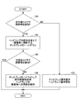
- FIG. 2 shows a flowchart of an example of a control routine executed by the ECU 16 in the vehicular field of view assistance device 10 of the present embodiment.
- FIG. 3A shows a captured image captured by the visible light camera 14 in a situation where the front of the host vehicle is relatively dark.
- FIG. 3B illustrates a captured image captured by the infrared camera 12 in the same situation as that illustrated in FIG. 3A. Note that FIG. 3B shows a captured image including a superimposed display that emphasizes the position of the pedestrian.
- FIG. 4A shows the front of the vehicle in a case where the light distribution by the headlamp 20 is performed on a predetermined region in front of the vehicle (that is, a normal region when no obstacle is detected). The figure showing the situation and the display of the display 18 is shown.
- FIG. 4B is a diagram illustrating a situation in front of the vehicle and a display on the display 18 when the light distribution by the headlamp 20 is performed on an area including an obstacle. Further, FIG. 4C is performed on the area including the obstacle in which the light distribution by the headlamp 20 is detected, but the front of the vehicle when the presence of the obstacle is not detected in the captured image by the visible light camera 14. The figure showing the situation and the display of the display 18 is shown.
- the vehicular visibility support apparatus 10 detects that the surroundings of the own vehicle is dark under the condition that the own vehicle is in an ignition-on state, or if the start switch by the own vehicle driver is turned on. It is activated to start visual support for the person.
- the vehicle vision support device 10 may be activated on condition that the headlamp 20 of the host vehicle is automatically radiating visible light when a manual switch is turned on or when an irradiation condition is established. .
- ECU16 commands imaging to the infrared camera 12 after starting. Then, the captured image supplied from the infrared camera 12 is acquired, and the captured image is displayed on the display 18.
- the driver of the own vehicle sees the display 18 around the vehicle that cannot be seen with his / her own eyes but can be seen with near infrared rays. It becomes possible to grasp the situation.
- the ECU 16 also executes the following processing every predetermined time. Specifically, first, by processing the captured image acquired from the infrared camera 12, it is determined whether or not the presence of an obstacle is detected on the road ahead of the host vehicle included in the captured image. Perform (step 100).
- the ECU 16 determines that the presence of an obstacle is not detected on the road ahead of the host vehicle included in the image captured by the infrared camera 12 (when a negative determination is made in step 100)
- the captured image acquired from the infrared camera 12 Is displayed on the display 18 and the light distribution area of the visible light from the headlamp 20 is set to a predetermined area in front of the vehicle (that is, a normal area when no obstacle is detected). (Step 102).
- the ECU 16 determines that the presence of an obstacle is detected on the road ahead of the host vehicle included in the image captured by the infrared camera 12 (when an affirmative determination is made in step 100)
- the ECU 16 uses the headlamp 20.
- Command the variable light distribution system 22 so that the irradiation direction of visible light faces the obstacle on the road or the obstacle on the road is included in the irradiation range of the visible light by the headlamp 20 (Step 104).
- the variable light distribution system 22 changes the irradiation direction of the visible light from the headlamp 20 so that an obstacle on the road is included in the irradiation range.
- the variable light distribution system 22 Is used to change the irradiation direction of the visible light from the headlamp 20 as described above, and tone-down the display of the image captured by the infrared camera 12 on the display 18 (step 104).
- the display in the display 18 may be darker than normal brightness or may not be displayed.
- the visible light irradiation by the headlamp 20 is performed using the variable light distribution system 22.
- the direction is changed, and the display on the display 18 of the captured image by the infrared camera 12 is toned down, so that the driver of the own vehicle is prompted to look directly on the road, and the obstacle on the road is viewed. It can be made easy to recognize by direct view.
- the ECU 16 uses the variable light distribution system 22 to change the irradiation direction of the visible light by the headlamp 20 as described above, and then processes the captured image acquired from the visible light camera 14 to obtain the captured image. It is determined whether or not the presence of an obstacle is detected on the road ahead of the host vehicle included in the vehicle (step 106).
- the road is present even though there is an obstacle for the own vehicle such as a pedestrian wearing black clothes that hardly reflects visible light on the road.
- an obstacle for the own vehicle such as a pedestrian wearing black clothes that hardly reflects visible light on the road.
- the obstacle itself and the vicinity of the obstacle are dark, and reflection of visible light from the obstacle is not sufficient. It can be judged that the detection using is difficult or impossible (see FIG. 3A). In this case, it can be determined that it is difficult or impossible for the driver of the vehicle to visually recognize the obstacle on the road.
- the driver visually recognizes the image captured by the infrared camera 12 from the tone-down state of the display 18 in order to make the driver recognize the presence of the obstacle on the road and the position of the obstacle. It is appropriate to change to an enabled state (tone-down release state) and to show the image captured by the infrared camera 12 through the display 18 to the host vehicle driver.
- the ECU 16 determines that the presence of an obstacle is detected on the road ahead of the host vehicle included in the image captured by the visible light camera 14 (when an affirmative determination is made in step 106), the ECU 16 ends the process.
- the ECU 16 determines that no obstacle is detected on the road ahead of the host vehicle included in the image captured by the visible light camera 14 (when a negative determination is made in step 106)
- the ECU 16 uses the headlamp 20.
- the image captured by the infrared camera 12 is changed from the tone-down state to a tone-down canceling state in which the driver can visually recognize the image, and the superimposed image highlighting the position of the obstacle on the image captured by the infrared camera 12 displayed on the display 18.
- the display is realized (see FIG. 3B; step 108).
- the driver of the own vehicle can see the image captured by the infrared camera 12 through the display 18 and on the road through the infrared light image displayed on the display 18. It is possible to check and recognize obstacles existing in In this case, the host vehicle driver can easily recognize an obstacle on the road by looking at the screen on the display 18 rather than looking directly on the road.
- the driver of the host vehicle looks at the screen on the display 18 to display the image. It is easy to confirm and recognize the presence and location of an obstacle present on the road through
- the presence of an obstacle on the road is detected based on the image captured by the infrared camera 12, while the obstacle exists on the road based on the image captured by the visible light camera 14.
- the captured image by the infrared camera 12 is displayed on the display 18 and the superimposed position highlighting the position of the obstacle is displayed, the driver of the vehicle is displayed on the road through the display 18. It is possible to easily recognize the obstacle.
- the image captured by the infrared camera 12 is displayed.
- Whether to display the image on the display 18 so as to be visible to the driver is switched depending on whether an obstacle is detected on the road based on the image captured by the visible light camera 14. That is, the image captured by the infrared camera 12 is displayed on the display 18 so that the driver can visually recognize the presence of an obstacle on the road based on the image captured by the visible light camera 14.
- the display 18 does not display it so that the driver can visually recognize the obstacle.
- the image captured by the infrared camera 12 is provided to the host vehicle driver via the display 18.
- the timing to be performed is limited to the case where the presence of an obstacle on the road is not detected based on the image captured by the visible light camera 14.
- the timing at which the driver of the own vehicle should look at the image captured by the infrared camera 12 through the display 18 is limited to the timing at which it is determined that the obstacle on the road cannot be visually recognized by direct viewing.
- the captured image from the infrared camera 12 can be provided to the driver of the vehicle through the display 18 regardless of whether the presence of an obstacle on the road is detected based on the captured image by the visible light camera 14.
- the visible light camera 14 it is possible to make it easier to understand the information on the presence or absence of obstacles on the road for the driver of the vehicle, and when there is an obstacle ahead of the vehicle while the vehicle is traveling, etc. It is possible to prompt the driver to recognize the presence of an obstacle.
- the above-described provision of the captured image by the infrared camera 12 to the host vehicle driver through the display 18 is performed by using the variable light distribution system 22 and the irradiation direction of the visible light from the headlamp 20 is the irradiation direction. This is performed in a situation where the range includes obstacles on the road. If the irradiation direction of the visible light from the headlamp 20 is varied as described above using the variable light distribution system 22, an obstacle on the road is normally illuminated by the visible light from the headlamp 20, so that It is considered possible for the vehicle driver to visually recognize the obstacle on the road.
- the obstacle is, for example, a pedestrian wearing black clothes that hardly reflects visible light
- the obstacle when the obstacle is irradiated with visible light from the headlamp 20, In some cases, the light may not be reflected effectively. In this case, the driver of the host vehicle may not be able to visually recognize the obstacle.
- the provision of the captured image by the infrared camera 12 to the driver of the vehicle through the display 18 is performed by the visible light from the headlamp 20 using the variable light distribution system 22. Since the irradiation direction of the vehicle is changed in such a way that obstacles on the road are included in the irradiation range, the driver of the own vehicle after changing the light distribution by the headlamp 20 using the variable light distribution system 22 However, even if the obstacle on the road cannot be seen directly, the obstacle on the road can be recognized through the display 18. Therefore, according to the present embodiment, it is possible to ensure safe traveling of the host vehicle.
- the pedestrian is visible light by the headlamp 20.
- the driver of the vehicle may not be able to see the pedestrian directly (see FIG. 4A).
- the headlamp 20 is used using the variable light distribution system 22.
- the visible light irradiation direction is changed so that the pedestrian is included in the irradiation range, and the display of the captured image by the infrared camera 12 on the display 18 is toned down (see FIG. 4B).
- the irradiation direction of the visible light from the headlamp 20 is changed as described above, normally, the pedestrian is illuminated by the visible light from the headlamp 20 and the reflected light returns to the host vehicle.
- the driver can visually recognize a pedestrian on the road.
- the image captured by the infrared camera 12 is displayed in a tone-down manner on the display 18, the host vehicle driver cannot grasp the situation ahead of the vehicle included in the image captured by the infrared camera 12. You are prompted to look directly at the person.
- the presence of the pedestrian on the road is detected based on the image captured by the infrared camera 12, while the road based on the image captured by the visible light camera 14 is detected.
- the display 18 is changed from the tone-down state to a state where the driver can visually recognize the image captured by the infrared camera 12 (tone-down release state), and Then, superimposed display is realized in which the presence position of the pedestrian is emphasized on the image captured by the infrared camera 12 displayed on the display 18 (see FIG. 4C).
- an image captured by the infrared camera 12 is displayed on the display 18 and the pedestrian's location is emphasized and superimposed, so that the vehicle driver can recognize the pedestrian on the road through the display 18. It becomes possible.
- the vehicle field-of-view assistance device 10 of the present embodiment when the vehicle driver surely recognizes an obstacle on the road, the timing on which the road should be directly viewed and the display 18 are displayed. Since it is possible to clearly separate the timing at which an image captured by the infrared camera 12 is to be confirmed, the safety of traveling of the host vehicle can be improved.
- the image captured by the infrared camera 12 corresponds to “different from the visible light image” described in the claims
- the display 18 corresponds to “predetermined display” described in the claims. is doing.
- the ECU 16 processes the captured image acquired from the visible light camera 14 and detects that there is an obstacle on the road ahead of the host vehicle that may affect the traveling of the host vehicle.
- the described “first obstacle detection means” processes the captured image acquired from the infrared camera 12 to detect that there is an obstacle on the road ahead of the host vehicle that may affect the traveling of the host vehicle.
- the “second obstacle detection means” described in the claims executes the processing of step 106 in the routine shown in FIG. 2, so that the “detection state determination means” described in the claims is displayed on the display 18. Is changed from the tone-down state to the tone-down canceling state in which the image captured by the infrared camera 12 is visible to the driver, and the infrared image displayed on the display 18 is changed.
- the “obstacle information presenting means” described in the claims is realized by the headlamp 20 using the variable light distribution system 22 by realizing the superimposed display that emphasizes the position where the obstacle is present on the image taken by the camera 12.
- the “irradiation direction changing means” described in the claims makes the image captured by the infrared camera 12 the presence of an obstacle.
- variable light distribution system 22 when it is detected that an obstacle is present on the road based on the image captured by the infrared camera 12, the variable light distribution system 22 is used to transmit the visible light from the headlamp 20.
- the irradiation direction is changed, and the display of the image captured by the infrared camera 12 on the display 18 is toned down. Further, after the irradiation direction of the visible light by the headlamp 20 is changed, the image captured by the visible light camera 14 is changed. If the presence of an obstacle on the road is not detected based on the above, the display on the display 18 is changed from the tone-down state to the tone-down release state, and the image captured by the infrared camera 12 is emphasized for the position where the obstacle exists.
- the present invention is not limited to this, and on the road based on the image captured by the visible light camera 14 when it is detected that an obstacle exists on the road based on the image captured by the infrared camera 12. If the presence of an obstacle is detected on the road based on the image picked up by the visible light camera 14 as a result of the determination, an infrared ray is detected.
- the infrared camera 12 applied to the display 18 It is also possible to perform highlighting of the position of the obstacle while continuing to display the captured image.
- the image captured by the infrared camera 12 is displayed on the display 18, while the infrared image is detected.
- the image captured by the infrared camera 12 is displayed on the display 18 and then captured by the visible light camera 14.
- the tone-down display on the display 18 is canceled and the image captured by the infrared camera 12 is displayed on the display 18 with a normal tone.
- the present invention is not limited to this, and the display of the image captured by the infrared camera 12 on the display 18 is detected based on the image captured by the infrared camera 12 that there is an obstacle on the road. Accordingly, the tone immediately before toning down is made different from the tone immediately after toning up when no obstacle is detected on the road based on the image captured by the visible light camera 14. It is good.
- the tone immediately before the above-mentioned tone is charged in the “first tone” described in the claims
- the tone after the tone down described above is the “second tone” described in the claims
- the tone immediately after the above-mentioned tone is charged. This corresponds to the “third tone” described in the range.
- the visible light emitted from the headlamp 20 is changed using the variable light distribution system 22.
- the irradiation direction is varied so that obstacles on the road are included in the irradiation range
- the present invention always varies the irradiation direction of visible light by the headlamp 20 when the above-described conditions are satisfied. It is not limited to that.
- the change in the irradiation direction of visible light by the headlamp 20 is set to a predetermined upper limit value (for example, the preceding vehicle).
- the presence of an obstacle on the road is detected based on the image captured by the infrared camera 12, and the image captured by the visible light camera 14 is detected. If the presence of an obstacle on the road is not detected based on the above, the obstacle position may be highlighted while continuing the display of the captured image by the infrared camera 12 on the display 18. According to such a modification, it becomes possible to realize the change of the irradiation direction of the visible light by the headlamp 20 in the own vehicle while ensuring the antiglare property to the occupant of the preceding vehicle or the oncoming vehicle.
- the routine shown in FIG. 2 is performed by the obstacle on the road whose presence is detected based on the image captured by the infrared camera 12 in the step 100 and the visible light camera 14 in the step 106.
- the process proceeds regardless of whether or not the obstacle on the road whose presence is detected based on the captured image is the same object, but the present invention is not limited to this, and the above step 106 is performed. Even if it is detected that an obstacle is present on the road based on the image captured by the visible light camera 14, the presence of the obstacle detected based on the image captured by the infrared camera 12 is detected. If it is determined that the same obstacle as the detected obstacle on the road does not exist, the process of step 108 may be executed next. .
- the routine shown in FIG. 2 is processed regardless of the speed of the host vehicle and the position of the obstacle with respect to the host vehicle.
- the present invention is not limited to this, and When the vehicle speed is higher than a predetermined value or when an obstacle is within a predetermined distance from the host vehicle, the time until the host vehicle reaches the obstacle is short.
- the processing of step 108 may be omitted after the negative determination of step 106 in order to facilitate promptly viewing the obstacle.
- the infrared camera 12 is mounted to detect the presence of an obstacle on the road ahead of the host vehicle, and then the visible light irradiation direction is changed and then the visible light is changed.
- the superimposed display is performed with emphasis on the position of the obstacle on the road included in the captured image.
- the present invention is not limited to this, and a vehicle such as a millimeter wave radar or a laser radar is mounted to detect the presence of an obstacle on the road ahead of the host vehicle.
- a warning display or a warning sound may be generated based on the detection of the obstacle by the radar.
Landscapes
- Engineering & Computer Science (AREA)
- Multimedia (AREA)
- Mechanical Engineering (AREA)
- Physics & Mathematics (AREA)
- General Physics & Mathematics (AREA)
- Theoretical Computer Science (AREA)
- Traffic Control Systems (AREA)
- Closed-Circuit Television Systems (AREA)
- Lighting Device Outwards From Vehicle And Optical Signal (AREA)
Abstract
Priority Applications (5)
| Application Number | Priority Date | Filing Date | Title |
|---|---|---|---|
| EP11866787.2A EP2717238B1 (fr) | 2011-06-02 | 2011-06-02 | Dispositif d'assistance de champ de vision de véhicule |
| PCT/JP2011/062724 WO2012164729A1 (fr) | 2011-06-02 | 2011-06-02 | Dispositif d'assistance de champ de vision de véhicule |
| CN201180071322.XA CN103582906B (zh) | 2011-06-02 | 2011-06-02 | 车辆用视野辅助装置 |
| JP2013517782A JP5742937B2 (ja) | 2011-06-02 | 2011-06-02 | 車両用視界支援装置 |
| US14/118,770 US9230178B2 (en) | 2011-06-02 | 2011-06-02 | Vision support apparatus for vehicle |
Applications Claiming Priority (1)
| Application Number | Priority Date | Filing Date | Title |
|---|---|---|---|
| PCT/JP2011/062724 WO2012164729A1 (fr) | 2011-06-02 | 2011-06-02 | Dispositif d'assistance de champ de vision de véhicule |
Publications (1)
| Publication Number | Publication Date |
|---|---|
| WO2012164729A1 true WO2012164729A1 (fr) | 2012-12-06 |
Family
ID=47258614
Family Applications (1)
| Application Number | Title | Priority Date | Filing Date |
|---|---|---|---|
| PCT/JP2011/062724 WO2012164729A1 (fr) | 2011-06-02 | 2011-06-02 | Dispositif d'assistance de champ de vision de véhicule |
Country Status (5)
| Country | Link |
|---|---|
| US (1) | US9230178B2 (fr) |
| EP (1) | EP2717238B1 (fr) |
| JP (1) | JP5742937B2 (fr) |
| CN (1) | CN103582906B (fr) |
| WO (1) | WO2012164729A1 (fr) |
Cited By (6)
| Publication number | Priority date | Publication date | Assignee | Title |
|---|---|---|---|---|
| WO2019039201A1 (fr) * | 2017-08-23 | 2019-02-28 | 日本精機株式会社 | Dispositif d'affichage pour véhicules |
| JP6526351B1 (ja) * | 2018-03-29 | 2019-06-05 | 三菱電機株式会社 | 車両照明制御装置、車両照明制御方法及び車両照明制御プログラム |
| WO2019111464A1 (fr) * | 2017-12-04 | 2019-06-13 | ソニー株式会社 | Dispositif et procédé de traitement d'image |
| JP2019138636A (ja) * | 2018-02-06 | 2019-08-22 | 京セラ株式会社 | 物体検出装置、物体検出システム |
| JP2019214348A (ja) * | 2018-06-14 | 2019-12-19 | クラリオン株式会社 | 物体認識装置 |
| DE112018007190B4 (de) | 2018-03-29 | 2024-08-01 | Mitsubishi Electric Corporation | Fahrzeugbeleuchtungssteuerungsvorrichtung,fahrzeugbeleuchtungssteuerungsverfahren undfahrzeugbeleuchtungssteuerungsprogramm |
Families Citing this family (29)
| Publication number | Priority date | Publication date | Assignee | Title |
|---|---|---|---|---|
| US9662061B2 (en) * | 2013-12-16 | 2017-05-30 | International Business Machines Corporation | Ultraviolet camera and display station for capturing reflected ultraviolet light |
| JP6252304B2 (ja) * | 2014-03-28 | 2017-12-27 | 株式会社デンソー | 車両用認知通知装置、車両用認知通知システム |
| JP6413621B2 (ja) * | 2014-10-22 | 2018-10-31 | 株式会社デンソー | 車載用物体判別装置 |
| CN105584416A (zh) * | 2014-10-28 | 2016-05-18 | 陈庆达 | 驾驶视觉辅助标示方法及其系统 |
| CN104501820B (zh) * | 2014-11-24 | 2018-12-21 | 朱今兰 | 一种智能城市定位导航系统 |
| CN104501818B (zh) * | 2014-11-24 | 2018-02-27 | 南京理工大学 | 一种基于盲区消除的车载导航系统 |
| CN104501817A (zh) * | 2014-11-24 | 2015-04-08 | 李青花 | 一种基于误差消除的车载导航系统 |
| CN104567902A (zh) * | 2014-11-24 | 2015-04-29 | 朱今兰 | 一种智慧城市交通管理系统 |
| CN104802711A (zh) * | 2015-04-28 | 2015-07-29 | 刘凌霞 | 感官成像原理辅助行驶的标示方法及其系统 |
| CN108885845B (zh) * | 2016-03-24 | 2021-02-26 | 三菱电机株式会社 | 辅助图像显示装置、辅助图像显示方法和计算机可读的记录介质 |
| JP6595401B2 (ja) * | 2016-04-26 | 2019-10-23 | 株式会社Soken | 表示制御装置 |
| JP6368958B2 (ja) * | 2016-05-12 | 2018-08-08 | 本田技研工業株式会社 | 車両制御システム、車両制御方法、および車両制御プログラム |
| US9747804B1 (en) | 2016-06-23 | 2017-08-29 | GM Global Technology Operations LLC | Object detection-based directional control of light and sound |
| JP6402752B2 (ja) * | 2016-08-04 | 2018-10-10 | トヨタ自動車株式会社 | 車両用照明装置 |
| US10025424B2 (en) * | 2016-08-15 | 2018-07-17 | Ford Global Technologies, Llc | Vehicle with headlight control |
| US10788840B2 (en) * | 2016-12-27 | 2020-09-29 | Panasonic Intellectual Property Corporation Of America | Information processing apparatus, information processing method, and recording medium |
| DE102017200574B4 (de) * | 2017-01-16 | 2019-12-12 | Robert Bosch Gmbh | Verfahren zum Überwachen eines Umfelds eines Fahrzeugs |
| FR3062742B1 (fr) * | 2017-02-07 | 2020-05-08 | Peugeot Citroen Automobiles Sa | Dispositif d’aide a la navigation routiere de nuit |
| EP3584120B1 (fr) * | 2017-02-17 | 2021-04-14 | Sumitomo Heavy Industries, Ltd. | Système de surveillance d'environnement de machine de travail |
| CN106864372A (zh) * | 2017-03-31 | 2017-06-20 | 寅家电子科技(上海)有限公司 | 实景互联网打车辅助系统及方法 |
| JP6816679B2 (ja) * | 2017-09-05 | 2021-01-20 | トヨタ自動車株式会社 | 車両の制御装置 |
| CN107728633B (zh) * | 2017-10-23 | 2020-12-18 | 广州极飞科技有限公司 | 获取目标物位置信息方法及装置、移动装置及其控制方法 |
| US11294380B2 (en) | 2018-05-11 | 2022-04-05 | Arnold Chase | Passive infra-red guidance system |
| US10750953B1 (en) | 2018-05-11 | 2020-08-25 | Arnold Chase | Automatic fever detection system and method |
| US11062608B2 (en) | 2018-05-11 | 2021-07-13 | Arnold Chase | Passive infra-red pedestrian and animal detection and avoidance system |
| US10467903B1 (en) | 2018-05-11 | 2019-11-05 | Arnold Chase | Passive infra-red pedestrian detection and avoidance system |
| JP7215228B2 (ja) * | 2019-03-01 | 2023-01-31 | トヨタ自動車株式会社 | 制御装置、制御方法、制御プログラム |
| US11554775B2 (en) | 2019-03-18 | 2023-01-17 | Arnold Chase | Passive infra-red guidance system |
| WO2020226138A1 (fr) * | 2019-05-09 | 2020-11-12 | 株式会社小糸製作所 | Système de support d'entraînement, véhicule et lampe pour véhicule |
Citations (8)
| Publication number | Priority date | Publication date | Assignee | Title |
|---|---|---|---|---|
| JP2005135037A (ja) * | 2003-10-29 | 2005-05-26 | Toyota Central Res & Dev Lab Inc | 車両用情報提示装置 |
| JP2006338594A (ja) * | 2005-06-06 | 2006-12-14 | Toyota Motor Corp | 歩行者認識装置 |
| JP2007045336A (ja) * | 2005-08-10 | 2007-02-22 | Sumitomo Electric Ind Ltd | 障害物検出システム及び障害物検出方法 |
| JP2007076378A (ja) | 2005-09-09 | 2007-03-29 | Nissan Motor Co Ltd | 車両用照明装置および照明方法 |
| JP2007263704A (ja) * | 2006-03-28 | 2007-10-11 | Toyota Central Res & Dev Lab Inc | 視認不可能領域抽出装置、及び視覚支援装置 |
| JP2008135856A (ja) * | 2006-11-27 | 2008-06-12 | Toyota Motor Corp | 物体認識装置 |
| JP2008230333A (ja) * | 2007-03-19 | 2008-10-02 | Mazda Motor Corp | 車両の運転支援装置 |
| JP2011087006A (ja) * | 2009-10-13 | 2011-04-28 | Denso Corp | 車両用表示装置 |
Family Cites Families (9)
| Publication number | Priority date | Publication date | Assignee | Title |
|---|---|---|---|---|
| JP3941757B2 (ja) | 2003-07-31 | 2007-07-04 | 日産自動車株式会社 | 車両用夜間歩行者報知装置 |
| TWI269727B (en) * | 2006-01-09 | 2007-01-01 | Ind Tech Res Inst | Method and apparatus of assistant monitor for vehicle |
| JP4506703B2 (ja) | 2006-03-27 | 2010-07-21 | トヨタ自動車株式会社 | 車両用前照灯制御装置 |
| JP5262057B2 (ja) | 2006-11-17 | 2013-08-14 | 株式会社豊田中央研究所 | 照射装置 |
| JP2008226140A (ja) | 2007-03-15 | 2008-09-25 | Mazda Motor Corp | 車両の運転支援装置 |
| JP2009107543A (ja) * | 2007-10-31 | 2009-05-21 | Panasonic Corp | 車両用照明装置 |
| JP4964195B2 (ja) | 2008-07-10 | 2012-06-27 | パナソニック株式会社 | 車両用照明装置 |
| JP5341465B2 (ja) | 2008-10-20 | 2013-11-13 | スタンレー電気株式会社 | 車両用前照灯 |
| JP2010212156A (ja) | 2009-03-11 | 2010-09-24 | Stanley Electric Co Ltd | 車両用前照灯 |
-
2011
- 2011-06-02 EP EP11866787.2A patent/EP2717238B1/fr not_active Not-in-force
- 2011-06-02 US US14/118,770 patent/US9230178B2/en not_active Expired - Fee Related
- 2011-06-02 CN CN201180071322.XA patent/CN103582906B/zh not_active Expired - Fee Related
- 2011-06-02 WO PCT/JP2011/062724 patent/WO2012164729A1/fr active Application Filing
- 2011-06-02 JP JP2013517782A patent/JP5742937B2/ja not_active Expired - Fee Related
Patent Citations (8)
| Publication number | Priority date | Publication date | Assignee | Title |
|---|---|---|---|---|
| JP2005135037A (ja) * | 2003-10-29 | 2005-05-26 | Toyota Central Res & Dev Lab Inc | 車両用情報提示装置 |
| JP2006338594A (ja) * | 2005-06-06 | 2006-12-14 | Toyota Motor Corp | 歩行者認識装置 |
| JP2007045336A (ja) * | 2005-08-10 | 2007-02-22 | Sumitomo Electric Ind Ltd | 障害物検出システム及び障害物検出方法 |
| JP2007076378A (ja) | 2005-09-09 | 2007-03-29 | Nissan Motor Co Ltd | 車両用照明装置および照明方法 |
| JP2007263704A (ja) * | 2006-03-28 | 2007-10-11 | Toyota Central Res & Dev Lab Inc | 視認不可能領域抽出装置、及び視覚支援装置 |
| JP2008135856A (ja) * | 2006-11-27 | 2008-06-12 | Toyota Motor Corp | 物体認識装置 |
| JP2008230333A (ja) * | 2007-03-19 | 2008-10-02 | Mazda Motor Corp | 車両の運転支援装置 |
| JP2011087006A (ja) * | 2009-10-13 | 2011-04-28 | Denso Corp | 車両用表示装置 |
Non-Patent Citations (1)
| Title |
|---|
| See also references of EP2717238A4 |
Cited By (13)
| Publication number | Priority date | Publication date | Assignee | Title |
|---|---|---|---|---|
| WO2019039201A1 (fr) * | 2017-08-23 | 2019-02-28 | 日本精機株式会社 | Dispositif d'affichage pour véhicules |
| JP7188397B2 (ja) | 2017-12-04 | 2022-12-13 | ソニーグループ株式会社 | 画像処理装置及び画像処理方法 |
| US11641492B2 (en) | 2017-12-04 | 2023-05-02 | Sony Corporation | Image processing apparatus and image processing method |
| WO2019111464A1 (fr) * | 2017-12-04 | 2019-06-13 | ソニー株式会社 | Dispositif et procédé de traitement d'image |
| JPWO2019111464A1 (ja) * | 2017-12-04 | 2021-01-14 | ソニー株式会社 | 画像処理装置及び画像処理方法 |
| JP2019138636A (ja) * | 2018-02-06 | 2019-08-22 | 京セラ株式会社 | 物体検出装置、物体検出システム |
| JP7193234B2 (ja) | 2018-02-06 | 2022-12-20 | 京セラ株式会社 | 物体検出装置、物体検出システム |
| US11117511B2 (en) | 2018-03-29 | 2021-09-14 | Mitsubishi Electric Corporation | Vehicle lighting control apparatus, vehicle lighting control method, and computer readable medium |
| JP6526351B1 (ja) * | 2018-03-29 | 2019-06-05 | 三菱電機株式会社 | 車両照明制御装置、車両照明制御方法及び車両照明制御プログラム |
| DE112018007189B4 (de) | 2018-03-29 | 2024-06-20 | Mitsubishi Electric Corporation | Fahrzeugbeleuchtungssteuerungsvorrichtung, fahrzeugbeleuchtungssteuerungsverfahren undfahrzeugbeleuchtungssteuerungsprogramm |
| DE112018007190B4 (de) | 2018-03-29 | 2024-08-01 | Mitsubishi Electric Corporation | Fahrzeugbeleuchtungssteuerungsvorrichtung,fahrzeugbeleuchtungssteuerungsverfahren undfahrzeugbeleuchtungssteuerungsprogramm |
| JP2019214348A (ja) * | 2018-06-14 | 2019-12-19 | クラリオン株式会社 | 物体認識装置 |
| JP7244221B2 (ja) | 2018-06-14 | 2023-03-22 | フォルシアクラリオン・エレクトロニクス株式会社 | 物体認識装置 |
Also Published As
| Publication number | Publication date |
|---|---|
| JPWO2012164729A1 (ja) | 2014-07-31 |
| EP2717238A4 (fr) | 2014-12-17 |
| CN103582906B (zh) | 2016-01-20 |
| JP5742937B2 (ja) | 2015-07-01 |
| US20140085476A1 (en) | 2014-03-27 |
| EP2717238A1 (fr) | 2014-04-09 |
| CN103582906A (zh) | 2014-02-12 |
| EP2717238B1 (fr) | 2016-11-09 |
| US9230178B2 (en) | 2016-01-05 |
Similar Documents
| Publication | Publication Date | Title |
|---|---|---|
| JP5742937B2 (ja) | 車両用視界支援装置 | |
| CN107444263B (zh) | 车辆用显示装置 | |
| CN107848465B (zh) | 具有盲区显示和警示系统的车辆视觉系统 | |
| CN108602465B (zh) | 车辆用图像显示系统及搭载了该图像显示系统的车辆 | |
| CN109070800A (zh) | 用于车辆的图像显示设备和方法 | |
| JP2003200755A (ja) | 車両用表示装置 | |
| CN109715467B (zh) | 车辆控制装置、车辆控制方法以及可移动体 | |
| JPWO2015037117A1 (ja) | 情報表示システム及び情報表示装置 | |
| WO2017122654A1 (fr) | Dispositif d'aide à la conduite et procédé d'aide à la conduite | |
| JP2008193339A (ja) | 後方監視装置 | |
| WO2014103223A1 (fr) | Dispositif de vision de nuit | |
| JP2010058742A (ja) | 車両用運転支援装置 | |
| US20180172993A1 (en) | Side view safety display in a motor vehicle | |
| CN110831840B (zh) | 用于在避让障碍物时辅助机动车使用者的方法、驾驶员辅助装置和机动车 | |
| JP2007072631A (ja) | 車載警報装置 | |
| JP6448714B2 (ja) | 情報表示システム | |
| EP3892489B1 (fr) | Afficheur de véhicule | |
| WO2013144998A1 (fr) | Appareil d'assistance à la reconnaissance visuelle pour véhicule | |
| JP7287199B2 (ja) | 車両用注視誘導装置 | |
| EP3888966B1 (fr) | Afficheur de véhicule | |
| JP2008195229A (ja) | 車両周辺監視装置 | |
| JP5289920B2 (ja) | 車両用警報装置 | |
| JP4257535B2 (ja) | 自動車夜間視認システムの表示領域 | |
| JP2017007581A (ja) | 車両安全制御装置 | |
| JP2019038373A (ja) | 視認補助装置 |
Legal Events
| Date | Code | Title | Description |
|---|---|---|---|
| 121 | Ep: the epo has been informed by wipo that ep was designated in this application |
Ref document number: 11866787 Country of ref document: EP Kind code of ref document: A1 |
|
| ENP | Entry into the national phase |
Ref document number: 2013517782 Country of ref document: JP Kind code of ref document: A |
|
| REEP | Request for entry into the european phase |
Ref document number: 2011866787 Country of ref document: EP |
|
| WWE | Wipo information: entry into national phase |
Ref document number: 2011866787 Country of ref document: EP |
|
| WWE | Wipo information: entry into national phase |
Ref document number: 14118770 Country of ref document: US |
|
| NENP | Non-entry into the national phase |
Ref country code: DE |