WO2012157097A1 - 車両の空調遠隔操作システム、サーバー、および、携帯端末 - Google Patents
車両の空調遠隔操作システム、サーバー、および、携帯端末 Download PDFInfo
- Publication number
- WO2012157097A1 WO2012157097A1 PCT/JP2011/061439 JP2011061439W WO2012157097A1 WO 2012157097 A1 WO2012157097 A1 WO 2012157097A1 JP 2011061439 W JP2011061439 W JP 2011061439W WO 2012157097 A1 WO2012157097 A1 WO 2012157097A1
- Authority
- WO
- WIPO (PCT)
- Prior art keywords
- vehicle
- air conditioning
- server
- information
- air
- Prior art date
- Legal status (The legal status is an assumption and is not a legal conclusion. Google has not performed a legal analysis and makes no representation as to the accuracy of the status listed.)
- Ceased
Links
Images


Classifications
-
- B—PERFORMING OPERATIONS; TRANSPORTING
- B60—VEHICLES IN GENERAL
- B60L—PROPULSION OF ELECTRICALLY-PROPELLED VEHICLES; SUPPLYING ELECTRIC POWER FOR AUXILIARY EQUIPMENT OF ELECTRICALLY-PROPELLED VEHICLES; ELECTRODYNAMIC BRAKE SYSTEMS FOR VEHICLES IN GENERAL; MAGNETIC SUSPENSION OR LEVITATION FOR VEHICLES; MONITORING OPERATING VARIABLES OF ELECTRICALLY-PROPELLED VEHICLES; ELECTRIC SAFETY DEVICES FOR ELECTRICALLY-PROPELLED VEHICLES
- B60L53/00—Methods of charging batteries, specially adapted for electric vehicles; Charging stations or on-board charging equipment therefor; Exchange of energy storage elements in electric vehicles
- B60L53/10—Methods of charging batteries, specially adapted for electric vehicles; Charging stations or on-board charging equipment therefor; Exchange of energy storage elements in electric vehicles characterised by the energy transfer between the charging station and the vehicle
- B60L53/14—Conductive energy transfer
-
- B—PERFORMING OPERATIONS; TRANSPORTING
- B60—VEHICLES IN GENERAL
- B60H—ARRANGEMENTS OF HEATING, COOLING, VENTILATING OR OTHER AIR-TREATING DEVICES SPECIALLY ADAPTED FOR PASSENGER OR GOODS SPACES OF VEHICLES
- B60H1/00—Heating, cooling or ventilating devices
- B60H1/00642—Control systems or circuits; Control members or indication devices for heating, cooling or ventilating devices
- B60H1/00735—Control systems or circuits characterised by their input, i.e. by the detection, measurement or calculation of particular conditions, e.g. signal treatment, dynamic models
- B60H1/00764—Control systems or circuits characterised by their input, i.e. by the detection, measurement or calculation of particular conditions, e.g. signal treatment, dynamic models the input being a vehicle driving condition, e.g. speed
- B60H1/00771—Control systems or circuits characterised by their input, i.e. by the detection, measurement or calculation of particular conditions, e.g. signal treatment, dynamic models the input being a vehicle driving condition, e.g. speed the input being a vehicle position or surrounding, e.g. GPS-based position or tunnel
-
- B—PERFORMING OPERATIONS; TRANSPORTING
- B60—VEHICLES IN GENERAL
- B60L—PROPULSION OF ELECTRICALLY-PROPELLED VEHICLES; SUPPLYING ELECTRIC POWER FOR AUXILIARY EQUIPMENT OF ELECTRICALLY-PROPELLED VEHICLES; ELECTRODYNAMIC BRAKE SYSTEMS FOR VEHICLES IN GENERAL; MAGNETIC SUSPENSION OR LEVITATION FOR VEHICLES; MONITORING OPERATING VARIABLES OF ELECTRICALLY-PROPELLED VEHICLES; ELECTRIC SAFETY DEVICES FOR ELECTRICALLY-PROPELLED VEHICLES
- B60L1/00—Supplying electric power to auxiliary equipment of vehicles
- B60L1/003—Supplying electric power to auxiliary equipment of vehicles to auxiliary motors, e.g. for pumps, compressors
-
- B—PERFORMING OPERATIONS; TRANSPORTING
- B60—VEHICLES IN GENERAL
- B60L—PROPULSION OF ELECTRICALLY-PROPELLED VEHICLES; SUPPLYING ELECTRIC POWER FOR AUXILIARY EQUIPMENT OF ELECTRICALLY-PROPELLED VEHICLES; ELECTRODYNAMIC BRAKE SYSTEMS FOR VEHICLES IN GENERAL; MAGNETIC SUSPENSION OR LEVITATION FOR VEHICLES; MONITORING OPERATING VARIABLES OF ELECTRICALLY-PROPELLED VEHICLES; ELECTRIC SAFETY DEVICES FOR ELECTRICALLY-PROPELLED VEHICLES
- B60L50/00—Electric propulsion with power supplied within the vehicle
- B60L50/50—Electric propulsion with power supplied within the vehicle using propulsion power supplied by batteries or fuel cells
- B60L50/52—Electric propulsion with power supplied within the vehicle using propulsion power supplied by batteries or fuel cells characterised by DC-motors
-
- B—PERFORMING OPERATIONS; TRANSPORTING
- B60—VEHICLES IN GENERAL
- B60L—PROPULSION OF ELECTRICALLY-PROPELLED VEHICLES; SUPPLYING ELECTRIC POWER FOR AUXILIARY EQUIPMENT OF ELECTRICALLY-PROPELLED VEHICLES; ELECTRODYNAMIC BRAKE SYSTEMS FOR VEHICLES IN GENERAL; MAGNETIC SUSPENSION OR LEVITATION FOR VEHICLES; MONITORING OPERATING VARIABLES OF ELECTRICALLY-PROPELLED VEHICLES; ELECTRIC SAFETY DEVICES FOR ELECTRICALLY-PROPELLED VEHICLES
- B60L53/00—Methods of charging batteries, specially adapted for electric vehicles; Charging stations or on-board charging equipment therefor; Exchange of energy storage elements in electric vehicles
- B60L53/30—Constructional details of charging stations
- B60L53/305—Communication interfaces
-
- B—PERFORMING OPERATIONS; TRANSPORTING
- B60—VEHICLES IN GENERAL
- B60L—PROPULSION OF ELECTRICALLY-PROPELLED VEHICLES; SUPPLYING ELECTRIC POWER FOR AUXILIARY EQUIPMENT OF ELECTRICALLY-PROPELLED VEHICLES; ELECTRODYNAMIC BRAKE SYSTEMS FOR VEHICLES IN GENERAL; MAGNETIC SUSPENSION OR LEVITATION FOR VEHICLES; MONITORING OPERATING VARIABLES OF ELECTRICALLY-PROPELLED VEHICLES; ELECTRIC SAFETY DEVICES FOR ELECTRICALLY-PROPELLED VEHICLES
- B60L53/00—Methods of charging batteries, specially adapted for electric vehicles; Charging stations or on-board charging equipment therefor; Exchange of energy storage elements in electric vehicles
- B60L53/60—Monitoring or controlling charging stations
- B60L53/68—Off-site monitoring or control, e.g. remote control
-
- B—PERFORMING OPERATIONS; TRANSPORTING
- B60—VEHICLES IN GENERAL
- B60L—PROPULSION OF ELECTRICALLY-PROPELLED VEHICLES; SUPPLYING ELECTRIC POWER FOR AUXILIARY EQUIPMENT OF ELECTRICALLY-PROPELLED VEHICLES; ELECTRODYNAMIC BRAKE SYSTEMS FOR VEHICLES IN GENERAL; MAGNETIC SUSPENSION OR LEVITATION FOR VEHICLES; MONITORING OPERATING VARIABLES OF ELECTRICALLY-PROPELLED VEHICLES; ELECTRIC SAFETY DEVICES FOR ELECTRICALLY-PROPELLED VEHICLES
- B60L2240/00—Control parameters of input or output; Target parameters
- B60L2240/10—Vehicle control parameters
- B60L2240/34—Cabin temperature
-
- B—PERFORMING OPERATIONS; TRANSPORTING
- B60—VEHICLES IN GENERAL
- B60L—PROPULSION OF ELECTRICALLY-PROPELLED VEHICLES; SUPPLYING ELECTRIC POWER FOR AUXILIARY EQUIPMENT OF ELECTRICALLY-PROPELLED VEHICLES; ELECTRODYNAMIC BRAKE SYSTEMS FOR VEHICLES IN GENERAL; MAGNETIC SUSPENSION OR LEVITATION FOR VEHICLES; MONITORING OPERATING VARIABLES OF ELECTRICALLY-PROPELLED VEHICLES; ELECTRIC SAFETY DEVICES FOR ELECTRICALLY-PROPELLED VEHICLES
- B60L2240/00—Control parameters of input or output; Target parameters
- B60L2240/60—Navigation input
- B60L2240/62—Vehicle position
- B60L2240/622—Vehicle position by satellite navigation
-
- B—PERFORMING OPERATIONS; TRANSPORTING
- B60—VEHICLES IN GENERAL
- B60L—PROPULSION OF ELECTRICALLY-PROPELLED VEHICLES; SUPPLYING ELECTRIC POWER FOR AUXILIARY EQUIPMENT OF ELECTRICALLY-PROPELLED VEHICLES; ELECTRODYNAMIC BRAKE SYSTEMS FOR VEHICLES IN GENERAL; MAGNETIC SUSPENSION OR LEVITATION FOR VEHICLES; MONITORING OPERATING VARIABLES OF ELECTRICALLY-PROPELLED VEHICLES; ELECTRIC SAFETY DEVICES FOR ELECTRICALLY-PROPELLED VEHICLES
- B60L2240/00—Control parameters of input or output; Target parameters
- B60L2240/70—Interactions with external data bases, e.g. traffic centres
-
- B—PERFORMING OPERATIONS; TRANSPORTING
- B60—VEHICLES IN GENERAL
- B60W—CONJOINT CONTROL OF VEHICLE SUB-UNITS OF DIFFERENT TYPE OR DIFFERENT FUNCTION; CONTROL SYSTEMS SPECIALLY ADAPTED FOR HYBRID VEHICLES; ROAD VEHICLE DRIVE CONTROL SYSTEMS FOR PURPOSES NOT RELATED TO THE CONTROL OF A PARTICULAR SUB-UNIT
- B60W10/00—Conjoint control of vehicle sub-units of different type or different function
- B60W10/30—Conjoint control of vehicle sub-units of different type or different function including control of auxiliary equipment, e.g. air-conditioning compressors or oil pumps
-
- Y—GENERAL TAGGING OF NEW TECHNOLOGICAL DEVELOPMENTS; GENERAL TAGGING OF CROSS-SECTIONAL TECHNOLOGIES SPANNING OVER SEVERAL SECTIONS OF THE IPC; TECHNICAL SUBJECTS COVERED BY FORMER USPC CROSS-REFERENCE ART COLLECTIONS [XRACs] AND DIGESTS
- Y02—TECHNOLOGIES OR APPLICATIONS FOR MITIGATION OR ADAPTATION AGAINST CLIMATE CHANGE
- Y02T—CLIMATE CHANGE MITIGATION TECHNOLOGIES RELATED TO TRANSPORTATION
- Y02T10/00—Road transport of goods or passengers
- Y02T10/60—Other road transportation technologies with climate change mitigation effect
- Y02T10/70—Energy storage systems for electromobility, e.g. batteries
-
- Y—GENERAL TAGGING OF NEW TECHNOLOGICAL DEVELOPMENTS; GENERAL TAGGING OF CROSS-SECTIONAL TECHNOLOGIES SPANNING OVER SEVERAL SECTIONS OF THE IPC; TECHNICAL SUBJECTS COVERED BY FORMER USPC CROSS-REFERENCE ART COLLECTIONS [XRACs] AND DIGESTS
- Y02—TECHNOLOGIES OR APPLICATIONS FOR MITIGATION OR ADAPTATION AGAINST CLIMATE CHANGE
- Y02T—CLIMATE CHANGE MITIGATION TECHNOLOGIES RELATED TO TRANSPORTATION
- Y02T10/00—Road transport of goods or passengers
- Y02T10/60—Other road transportation technologies with climate change mitigation effect
- Y02T10/7072—Electromobility specific charging systems or methods for batteries, ultracapacitors, supercapacitors or double-layer capacitors
-
- Y—GENERAL TAGGING OF NEW TECHNOLOGICAL DEVELOPMENTS; GENERAL TAGGING OF CROSS-SECTIONAL TECHNOLOGIES SPANNING OVER SEVERAL SECTIONS OF THE IPC; TECHNICAL SUBJECTS COVERED BY FORMER USPC CROSS-REFERENCE ART COLLECTIONS [XRACs] AND DIGESTS
- Y02—TECHNOLOGIES OR APPLICATIONS FOR MITIGATION OR ADAPTATION AGAINST CLIMATE CHANGE
- Y02T—CLIMATE CHANGE MITIGATION TECHNOLOGIES RELATED TO TRANSPORTATION
- Y02T10/00—Road transport of goods or passengers
- Y02T10/60—Other road transportation technologies with climate change mitigation effect
- Y02T10/72—Electric energy management in electromobility
-
- Y—GENERAL TAGGING OF NEW TECHNOLOGICAL DEVELOPMENTS; GENERAL TAGGING OF CROSS-SECTIONAL TECHNOLOGIES SPANNING OVER SEVERAL SECTIONS OF THE IPC; TECHNICAL SUBJECTS COVERED BY FORMER USPC CROSS-REFERENCE ART COLLECTIONS [XRACs] AND DIGESTS
- Y02—TECHNOLOGIES OR APPLICATIONS FOR MITIGATION OR ADAPTATION AGAINST CLIMATE CHANGE
- Y02T—CLIMATE CHANGE MITIGATION TECHNOLOGIES RELATED TO TRANSPORTATION
- Y02T90/00—Enabling technologies or technologies with a potential or indirect contribution to GHG emissions mitigation
- Y02T90/10—Technologies relating to charging of electric vehicles
- Y02T90/12—Electric charging stations
-
- Y—GENERAL TAGGING OF NEW TECHNOLOGICAL DEVELOPMENTS; GENERAL TAGGING OF CROSS-SECTIONAL TECHNOLOGIES SPANNING OVER SEVERAL SECTIONS OF THE IPC; TECHNICAL SUBJECTS COVERED BY FORMER USPC CROSS-REFERENCE ART COLLECTIONS [XRACs] AND DIGESTS
- Y02—TECHNOLOGIES OR APPLICATIONS FOR MITIGATION OR ADAPTATION AGAINST CLIMATE CHANGE
- Y02T—CLIMATE CHANGE MITIGATION TECHNOLOGIES RELATED TO TRANSPORTATION
- Y02T90/00—Enabling technologies or technologies with a potential or indirect contribution to GHG emissions mitigation
- Y02T90/10—Technologies relating to charging of electric vehicles
- Y02T90/14—Plug-in electric vehicles
-
- Y—GENERAL TAGGING OF NEW TECHNOLOGICAL DEVELOPMENTS; GENERAL TAGGING OF CROSS-SECTIONAL TECHNOLOGIES SPANNING OVER SEVERAL SECTIONS OF THE IPC; TECHNICAL SUBJECTS COVERED BY FORMER USPC CROSS-REFERENCE ART COLLECTIONS [XRACs] AND DIGESTS
- Y02—TECHNOLOGIES OR APPLICATIONS FOR MITIGATION OR ADAPTATION AGAINST CLIMATE CHANGE
- Y02T—CLIMATE CHANGE MITIGATION TECHNOLOGIES RELATED TO TRANSPORTATION
- Y02T90/00—Enabling technologies or technologies with a potential or indirect contribution to GHG emissions mitigation
- Y02T90/10—Technologies relating to charging of electric vehicles
- Y02T90/16—Information or communication technologies improving the operation of electric vehicles
Definitions
- the present invention relates to an air-conditioning remote control system for pre-air-conditioning of a vehicle interior by starting a vehicle air-conditioning device by remote control in advance before boarding.
- an air-conditioning remote control system in which a vehicle air-conditioning device is activated in advance by remote operation before boarding to perform pre-air-conditioning in the passenger compartment.
- an operation command for an air conditioner is transmitted from a mobile phone to an in-vehicle monitor device via a base station.
- the in-vehicle monitor device determines whether or not the in-vehicle battery voltage is equal to or higher than a set voltage at which the air conditioner can be operated, and operates the air conditioner if the in-vehicle battery voltage is equal to or higher than the set voltage. Then, the in-vehicle monitor device notifies the mobile phone whether or not the air conditioner has been activated.
- the present invention has been made in order to cope with the above-described problem.
- the vehicle user performs a pre-air conditioning start operation from the mobile terminal, the vehicle user is notified of the air conditioning operation state of the air conditioner in a timely manner.
- a feature of the present invention is that a remote operation command from a portable terminal (300) carried by a vehicle user is transmitted via a server (210) provided in an information center (200) that handles vehicle information.
- the vehicle air-conditioning remote operation for pre-air-conditioning the vehicle interior by starting the air-conditioning device (180) of the vehicle before boarding by transmitting to the vehicle-mounted communication device (150) of the vehicle specified by the portable terminal
- a cooling / heating prediction means (S20) provided outside the vehicle for predicting whether the air conditioner is to be cooled or heated according to the remote operation command, and displaying the cooling / heating prediction result on the screen of the portable terminal
- a display control means (S33) provided outside the vehicle for predicting whether the air conditioner is to be cooled or heated according to the remote operation command, and displaying the cooling / heating prediction result on the screen of the portable terminal.
- the start command is transmitted to the server by the vehicle user operating the portable terminal and transmitting the pre-air conditioning start command.
- the server receives the pre-air conditioning start command from the mobile terminal, the server transmits an air-conditioner activation request command to the in-vehicle communication device of the vehicle specified by the mobile terminal.
- the air conditioner is activated.
- the cooling / heating prediction means performs cooling / heating prediction on whether the air conditioner is to be cooled or heated by a remote operation command, and the display control means displays the cooling / heating prediction result on the screen of the portable terminal. If the air conditioning operation state is determined on the vehicle side after the pre-air conditioning start command (remote operation command) is transmitted to the in-vehicle communication device, notification to the portable terminal in the air conditioning operation state is delayed. Further, since the temperature in the vehicle interior cannot be determined unless the air in the vehicle interior is circulated by the air conditioner, it is difficult to immediately determine the air conditioning operation state.
- the air conditioning prediction means performs air conditioning prediction outside the vehicle. Therefore, it is possible to predict the cooling / heating outside the vehicle without determining the cooling / heating state on the vehicle side and then transmitting the determination result to the mobile terminal via the information center. can do. As a result, it is possible to inform the vehicle user of the air conditioning condition in a timely manner. Thereby, the vehicle user can confirm the cooling / heating state without waiting for a long time when the start instruction operation of the pre-air conditioning is performed, and convenience is improved.
- the air conditioning prediction means obtains the air conditioning operation state from other information, without being based on the actual air conditioning operation state at the present time.
- cooling / heating prediction means performs the cooling / heating prediction based on position information of the vehicle and temperature information at a vehicle position specified by the position information.
- the cooling / heating prediction means acquires position information indicating the position of the vehicle (vehicle specified by the portable terminal), and acquires temperature information at the vehicle position specified by the position information. Then, for example, air conditioning prediction is performed by comparing the air temperature specified by the air temperature information (the air temperature when starting the pre-air-conditioning) with a threshold for determination.
- the air conditioning prediction can be easily performed, and the vehicle user can be notified of the air conditioning status in a timely manner.
- Another feature of the present invention is that after the air conditioner is started, the air outlet information of the air conditioner is acquired, the air conditioning prediction is performed based on the air outlet information, and the air conditioning prediction result by the air conditioning predicting unit is obtained.
- an air conditioning prediction update means S44, S45 for updating the air conditioning prediction result based on the outlet information.
- the cooling / heating prediction update means acquires the air outlet information of the air conditioner after the air conditioner is activated.
- the outlet information represents information indicating the setting state of the outlet for sending air-conditioning air into the passenger compartment.
- the vehicle is provided with a plurality of air outlets, for example, a front air outlet that allows air to flow toward the front of the occupant, and a foot air outlet that sends air toward the feet of the occupant. When cooling is performed, cool air is sent from the front outlet, and when heating is performed, warm air is sent from the foot outlet.
- the air conditioning prediction update means performs air conditioning prediction based on the air outlet information representing the setting state of the air outlet, and updates the air conditioning prediction result by the air conditioning prediction means to the air conditioning prediction result based on the air outlet information. Therefore, it is possible to switch to highly accurate air conditioning prediction.
- the display control means displays the updated cooling / heating prediction result on the screen of the portable terminal. Thereby, the vehicle user can know the updated air conditioning state.
- the position information transmitting means (150) for transmitting vehicle position information to the server every time a predetermined timing arrives, and the server.
- position information storage means (214) for storing the position information of the vehicle transmitted from the position information transmission means, wherein the cooling / heating prediction means is the latest vehicle position information stored in the position information storage means.
- Temperature information at the vehicle position specified by (1) is acquired (S21 to S22), and the air conditioning prediction is performed by comparing the temperature specified by the temperature information and a determination threshold (S23 to S25).
- the in-vehicle communication device is provided with position information transmission means
- the server is provided with position information storage means.
- the position information transmitting means transmits the vehicle position information to the server every time a predetermined timing arrives.
- the position information storage unit stores the vehicle position information transmitted from the position information transmission unit.
- the air conditioning predicting means obtains the latest position information of the vehicle specified by the portable terminal for which the pre-air-conditioning remote operation command has been issued from the position information storage means, and obtains temperature information at the vehicle position specified by the position information. To do. Then, the temperature specified by the temperature information (the temperature when pre-air conditioning is started) is compared with the determination threshold value to perform cooling / heating prediction.
- the server side knows in advance the position of the vehicle when pre-air-conditioning is performed, it is possible to predict air-conditioning in a short time. Therefore, it is possible to inform the vehicle user in a timely manner about the air conditioning condition.
- the cooling / heating prediction means is provided in the server and transmits the cooling / heating prediction result to the portable terminal.
- the present invention can be applied to a server used in an air conditioning remote control system for a vehicle.
- the server includes the air conditioning prediction unit and transmits the air conditioning prediction result to the mobile terminal. is there.
- the present invention can be applied to a portable terminal used in an air conditioning remote control system for a vehicle, and the feature thereof is a portable terminal that receives the cooling / heating prediction result transmitted from a server, wherein the display control means The cooling / heating prediction result transmitted from the server is displayed on the screen.
- the server performs air conditioning prediction and transmits the air conditioning prediction result to the mobile terminal.
- the portable terminal displays the air conditioning prediction result transmitted from the server on the screen. Therefore, according to the present invention, the vehicle user can check the cooling / heating state without waiting for a long time when performing the pre-air-conditioning start command operation.
- Another feature of the present invention is a server used in a vehicle air-conditioning remote control system, which transmits information necessary for performing the air-conditioning prediction to the portable terminal (S12).
- Another feature of the present invention is a portable terminal that receives information necessary for performing the cooling / heating prediction transmitted from a server, the portable terminal comprising the cooling / heating prediction means and the display control means, Air conditioning prediction is performed based on the transmitted information (S20 ′), and the air conditioning prediction result is displayed on the screen.
- information necessary for predicting cooling and heating by the server is acquired, and the information is transmitted to the mobile terminal.
- the mobile terminal receives the information transmitted from the server, performs air conditioning prediction based on the information, and displays the air conditioning prediction result on the screen.
- the server acquires temperature information at the vehicle position and transmits it to the mobile terminal, and the mobile terminal performs air conditioning prediction based on the received temperature information.
- the server transmits vehicle position information to the mobile terminal, and the mobile terminal acquires temperature information at the vehicle position specified by the vehicle position information, and performs air conditioning prediction based on the temperature information. Therefore, according to the present invention, the vehicle user can check the cooling / heating state without waiting for a long time when performing the pre-air-conditioning start command operation.
- the vehicle is provided in an information center that handles vehicle information, receives a remote operation command from a portable terminal carried by a vehicle user, and is specified by the portable terminal before boarding
- the server that sends a command for starting the air conditioning device of the vehicle to execute pre-air conditioning in the vehicle interior to the in-vehicle communication device of the vehicle, whether the air conditioning device is cooled or heated by the remote operation command
- an air conditioning prediction unit that performs air conditioning prediction and a display control unit that transmits information for displaying the air conditioning prediction result on a screen of the mobile terminal to the mobile terminal.
- a remote operation command related to pre-air conditioning is transmitted to an in-vehicle communication device of a specific vehicle via a server provided in an information center that handles vehicle information.
- a cooling / heating prediction means that performs cooling / heating prediction as to whether the air conditioning device is to be cooled or heated by the remote operation command;
- a display control means for displaying the cooling / heating prediction result on a screen.
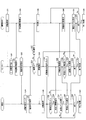
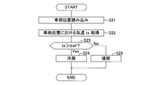
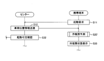
- FIG. 1 is a schematic configuration diagram of an information communication system for a vehicle to which an air conditioning remote control system according to an embodiment of the present invention is applied. It is a flowchart showing a pre air conditioning control routine. It is a figure showing transition of the screen of a portable terminal. It is a flowchart showing an air-conditioning prediction routine. It is a partial flowchart showing the modification of a pre air conditioning control routine.
- FIG. 1 shows a vehicle information communication system.
- the air conditioning remote control system of this embodiment is applied to this information communication system.
- the vehicle information communication system organically connects the vehicle 100, the vehicle information center 200, and the mobile terminal 300 owned by the vehicle user using an external communication network 400 such as the Internet, and provides various types of information to the vehicle user. It is possible to provide services.
- the vehicle 100 is provided with a plurality of electronic control devices 110 (hereinafter referred to as vehicle ECUs 110) that control the state of the vehicle.
- vehicle ECUs 110 Each vehicle ECU 110 is connected to a CAN communication line 120 of a CAN (Controller Area Network) communication system, and can transmit and receive various signals via the CAN communication line 120.
- CAN communication line 120 of a CAN (Controller Area Network) communication system
- an air conditioning ECU 110a serving as a control unit of the air conditioner 180 (auto air conditioner) is provided.
- vehicle ECU 110 includes a microcomputer, a memory, an input / output interface, and a drive circuit for inputting various sensor signals to drive various actuators.
- the CAN communication line 120 is connected to a data communication module 150 (hereinafter referred to as DCM 150) for connecting to the external communication network 400 and communicating with the vehicle information center 200.
- the DCM 150 obtains control information through data communication with the vehicle ECU 110 via the CAN communication line 120 and the external communication control unit 151 for data communication with the server 210 of the vehicle information center 200 via the external communication network 400.
- a main control unit 152 that outputs a command to the vehicle ECU 110, and a GPS unit 153 that detects the current position coordinates of the host vehicle based on radio waves from GPS satellites.
- the DCM 150 includes a microcomputer as a main part, and includes a memory, a wireless communication circuit, an input / output interface, and the like.
- the CAN communication line 120 is connected to a short-range communication control device 160 as a communication interface for performing short-range wireless communication with the mobile terminal 300.
- Bluetooth is used as the communication method of the short-range communication control device 160, but other short-range wireless communication methods such as Wi-Fi may be employed.
- the CAN communication line 120 is connected to a navigation device 170 that guides the vehicle to the destination.
- the navigation device 170 includes a vehicle position detection unit that detects the position and traveling direction of the vehicle, a memory that stores various information such as map data, a microcomputer that executes an application for guiding the vehicle to a destination, and a touch panel
- a human interface including a liquid crystal display and a speaker is provided (not shown for each component).
- the vehicle information center 200 is a facility that acquires various types of vehicle information from the vehicle 100 and provides various service information to vehicle users.
- the vehicle information center 200 is provided with a server 210 having a microcomputer as a main part.
- the server 210 is connected to the external communication network 400 to perform communication control, a vehicle control server 211 that manages vehicle information, a vehicle information server 212 that manages vehicle information, a user information server 213 that manages vehicle user information, and vehicle information
- a vehicle information storage unit 214 that stores a database and a user information storage unit 215 that stores a database of user information are provided.
- the server 210 obtains related information that associates an ID (information corresponding to a registration number or a chassis number) identifying the vehicle 100 and an ID (user name, phone number of the mobile terminal 300, mail address, etc.) identifying the vehicle user. It is configured so that information specified by the other ID can be extracted by specifying one of the IDs.
- the vehicle information server 212 has a function of remotely operating the vehicle 100 as well as managing vehicle information.
- a mobile phone such as a smartphone is used as the mobile terminal 300 owned by the vehicle user.
- the mobile terminal 300 includes an external communication control unit 301 that is a communication interface for connecting to the external communication network 400, a short-range communication control unit 302 that is a communication interface for performing short-range wireless communication using Bluetooth,
- a GPS unit 303 that detects the current position coordinates of the mobile terminal 300 based on radio waves from GPS satellites, a touch-panel liquid crystal display 304 that serves both as a display and an operating device, and a micro that manages communication control and various applications.
- a main control unit 305 having a computer and a nonvolatile memory 306 for storing application programs and various data are provided.
- the mobile terminal 300 has a telephone function, a mail function, a function of connecting to the Internet, a function of executing various application programs, and a function of connecting to the server 210 of the vehicle information center 200 to exchange various information. .
- the vehicle 100 to which the information communication system is applied in the present embodiment is an electric vehicle that drives a traveling motor with battery power, or a battery that includes a traveling motor and an internal combustion engine and serves as a power source for the traveling motor.
- a plug-in hybrid vehicle that can be recharged is preferable, but it may be a conventional vehicle that travels by an internal combustion engine that does not include a travel motor, and does not ask the drive type.
- various information regarding the vehicle 100 is transmitted from the DCM 150 to the server 210 of the vehicle information center 200 together with a vehicle ID (information corresponding to a registration number and a chassis number).
- a vehicle ID information corresponding to a registration number and a chassis number.
- the DCM 150 acquires information representing the state of charge (SOC) of the battery detected by the ECU 110 that manages battery charging from the CAN communication line 120, and combines the acquired SOC information with the vehicle ID and vehicle position information. It periodically transmits to the server 210 of the vehicle information center 200.
- SOC state of charge
- the server 210 of the vehicle information center 200 can grasp the SOC of the battery of the vehicle 100 together with the vehicle position, and when the SOC is decreasing, the charging available within the cruising range of the vehicle 100 is possible.
- the station is searched using the Internet or the like, a charging prompt message is transmitted to the mobile user's portable terminal 300, and a search result (charging station list or the like) is transmitted to the vehicle user's portable terminal 300.
- the DCM 150 sets a period from when the ignition switch (or an accessory switch) is turned on to when it is turned off as one section (referred to as one trip section), and driving such as travel distance, travel time, and power consumption in this one trip section.
- the information is transmitted to the server 210 together with the vehicle ID and the vehicle position information.
- the server 210 stores the received driving information and vehicle position information in the vehicle information storage unit 214 in association with the vehicle ID.
- the vehicle user can also start the application of the portable terminal 300 and obtain necessary information from the server 210 as appropriate. For example, when the vehicle user activates an application installed in the mobile terminal 300 and requests the server 210 for information regarding power consumption / fuel consumption, the server 210 is based on the driving information stored in the vehicle information storage unit 214. Then, information corresponding to the request of the vehicle user is generated and transmitted to the mobile terminal 300.
- the vehicle position information transmitted every time the travel of one trip section is completed is used as information for performing air conditioning prediction during pre-air conditioning described later.
- the vehicle user can transmit the latest map information, facility information, etc. downloaded to the mobile terminal 300 from the Internet site, for example, to the vehicle 100 side.
- the information downloaded to the portable terminal 300 is transmitted from the short-range communication control unit 302 to the short-range communication control device 160 of the vehicle 100 and stored in the memory of the navigation device 170.
- the vehicle 100 can be remotely operated via the server 210 by transmitting an operation command from the mobile terminal 300 of the vehicle user to the server 210 of the vehicle information center 200.
- One of the functions is pre-air conditioning.
- the pre-air-conditioning means that the air-conditioner 180 is activated in advance and the vehicle interior is air-conditioned before boarding.
- the vehicle user operates the mobile terminal 300 to instruct start / stop of pre-air conditioning.
- the air conditioner 180 has a function of displaying on the display 304 of the portable terminal 300 the air conditioning status indicating whether the air conditioner 180 is cooling or heating.
- the air conditioner 180 for air-conditioning the interior of the vehicle includes an air-conditioning ECU 110a that includes a microcomputer as a main part and performs air-conditioning control, an output device group 181 such as a compressor, a fan, and a blow-out switching damper, and temperatures in the vehicle interior and the exterior of the vehicle interior.
- a sensor group 182 such as a temperature sensor for detecting the solar radiation and a solar radiation sensor for detecting the amount of solar radiation.
- the air conditioning ECU 110a controls the operation of the output device group 181 based on the detection value detected by the sensor group 182 and the set temperature set by the occupant, thereby air-conditioning the vehicle interior.
- FIG. 2 is a flowchart showing a pre-air conditioning control routine.
- the pre-air conditioning is performed by the cooperation of the mobile terminal 300, the server 210 of the vehicle information center 200, the DCM 150 of the vehicle 100, and the ECU 110.
- the vehicle user operates the mobile terminal 300 to start the pre-air conditioning application in order to start the pre-air conditioning.
- the pre-air conditioning application is stored in advance in the nonvolatile memory 306 of the portable terminal 304.
- the main control unit 305 of the mobile terminal 300 that executes the pre-air-conditioning application program is simply referred to as the mobile terminal 300.
- a pre-air conditioning initial screen is displayed on the display 304 of the mobile terminal 300 as shown in FIG.
- the vehicle user touches the pre-air conditioning start button icon 304a displayed on the initial screen.
- the portable terminal 300 transmits the start request
- the mobile terminal 300 always transmits the mobile terminal ID together when communicating with the server 210.
- the server 210 receives the pre-air conditioning activation request transmitted from the mobile terminal 300, the server 210 performs a cooling / heating prediction process in step S20.
- the air conditioning prediction process is performed according to the air conditioning prediction routine shown in FIG.
- the server 210 When starting the air conditioning prediction routine, the server 210 first reads vehicle position information stored in the vehicle information storage unit 214 in step S21.
- the vehicle position information is transmitted from the DCM 150 to the server 210 together with the driving information and the vehicle ID of one trip section each time the ignition switch (or accessory switch) of the vehicle 100 is switched from the on state to the off state. It is stored in the vehicle information storage unit 214. Therefore, in step S21, the server 210 reads the latest vehicle position information of the vehicle 100 corresponding to the ID of the mobile terminal 300 from the vehicle information storage unit 214, thereby grasping the current position of the vehicle 100 that is to perform pre-air conditioning. To do.
- step S22 the server 210 acquires temperature information at the vehicle position.
- the server 210 performs processing for acquiring temperature information for each region provided by the temperature information center or the like from the Internet or the like and always storing the latest temperature information in a memory (or the vehicle information storage unit 214). Yes.
- step S22 the temperature information at the start of pre-air conditioning at the vehicle position is read from the latest temperature information stored in the memory, and the temperature tx at the vehicle position is acquired.
- step S23 the server 210 determines whether or not the temperature tx exceeds a preset threshold value tref for air conditioning, and if the temperature tx is higher than the threshold value tref, in step S24 the air conditioning prediction is “ When the temperature is set to “cooling” and the temperature tx is equal to or lower than the threshold value tref, the cooling / heating prediction is set to “heating”.
- the threshold value tref is set to one, but a threshold value tref1 for cooling determination and a threshold value tref2 for heating determination ( ⁇ tref1) are prepared, and the temperature tx is higher than the threshold value tref1 for cooling determination.
- the cooling / heating prediction may be set to “cooling”, and when the temperature tx is lower than the heating determination threshold value tref2, the cooling / heating prediction may be set to “heating”.
- step S24 or step S25 the server 210 ends the air conditioning prediction routine.
- the server 210 When the cooling / heating prediction is completed, the server 210 notifies the portable terminal 300 of the cooling / heating state representing the cooling / heating prediction result through communication using HTTPS (Hypertext Transfer Protocol over Secure Socket Layer) in step S31 of FIG. Further, in step S32, the server 210 activates the DCM 150 by SMS (Short Message Service) or incoming voice to the DCM 150 of the vehicle 100 corresponding to the ID of the mobile terminal 300 (hereinafter simply referred to as DCM 150). The command and the pre-air-conditioning activation availability confirmation command are transmitted.
- SMS Short Message Service
- the cooling / heating state display unit 304c on the pre-air-conditioning state screen displayed on the display 304 is displayed in the cooling / heating state (step S33) as shown in FIG. Display in a color according to the air conditioning prediction result.
- the air-conditioning state display unit 304c is displayed in blue when the air-conditioning state is “cooling” and orange when the air-conditioning state is “heating”. Therefore, the vehicle user can grasp the air conditioning state from the screen displayed on the mobile terminal 300 at this stage.
- the pre-air conditioning start button icon 304a displayed on the pre-air conditioning initial screen is switched to the pre-air conditioning end button icon 304b.
- DCM 150 of vehicle 100 is activated by the activation command transmitted from server 210 to activate the CAN communication system, and to vehicle ECU 110 that checks the vehicle state based on the command for confirming whether or not pre-air conditioning is activated. Send a start permission confirmation command.
- Pre-air conditioning is limited so that it can be executed only when predetermined conditions are satisfied. For example, conditions are set such that all doors and trunks of the vehicle are closed, all door locks are engaged, and that an ignition switch and an accessory switch are turned off.
- vehicle ECU 110 checks the vehicle state and transmits the check result to DCM 150.
- the DCM 150 transmits an activation permission report to the server 210 by communication using HTTP (Hypertext Transfer Protocol). Thereafter, HTTP is used for communication between the DCM 150 and the server 210.
- HTTP Hypertext Transfer Protocol
- step S36 the server 210 determines whether or not the pre-air conditioning activation is permitted based on the received activation permission report. If the activation is not permitted, the server 210 carries the activation disapproval notification in step S37. It transmits to the terminal 300. When receiving the activation disapproval notification, the portable terminal 300 displays that the pre-air conditioning cannot be activated on the display screen in step S38, and then returns the display screen to the initial screen.
- the server 210 transmits a pre-air conditioning activation instruction to the DCM 150 in step S39.
- DCM 150 receives the pre-air conditioning activation instruction
- DCM 150 transmits an air conditioning start command to air conditioning ECU 110a in step S40.
- air-conditioning ECU110a performs an air-conditioner starting process, and the air conditioning of a vehicle interior is started.
- the server 210 After transmitting the start instruction, the server 210 transmits a cooling / heating notification instruction in step S41. In this case, information specifying the timing (timer time) for notifying the cooling / heating state is transmitted.
- the DCM 150 determines whether or not the timing for notifying the air-conditioning state has arrived in step S42. If it is not the time to notify the air-conditioning state, the pre-air-conditioning is terminated in step S43. Judge whether to do. The pre-air conditioning is ended by an end instruction from the server 210. Therefore, in step S43, it is determined whether or not an end instruction is transmitted from the server 210.
- the DCM 150 waits until the timing for notifying the cooling / heating state arrives while not receiving the end instruction, and when the timing for notifying the cooling / heating state arrives (S42: Yes), the air outlet ECU 110a from the air conditioning ECU 110a in step S44. Read information.
- the vehicle 100 is provided with a plurality of air outlets, for example, a front air outlet (face register) for flowing air toward the front of the occupant and a foot outlet for sending air toward the feet of the occupant.
- the air conditioning ECU 110a operates the air outlet switching damper to switch the air outlet through which the air is sent into the vehicle interior.
- the outlet information is information indicating from which outlet the air is sent, that is, information indicating the setting state of the outlet.
- the outlet information can be acquired from the control information of the outlet switching damper, for example.
- DCM 150 When DCM 150 reads the outlet information from air conditioning ECU 110a, DCM 150 transmits notification of the outlet information to server 210 in step S44. In step S45, the server 210 transmits an air conditioning condition notification to the mobile terminal 300 based on the outlet information. In this case, if the server 210 is in a mode in which air is blown using the front air outlet (face mode), the air conditioning state is predicted to be “cooling”, and the mode in which air is blown using the foot air outlet (foot mode). ), The air conditioning state is predicted as “heating”, and the predicted air conditioning state notification is transmitted to the mobile terminal 300.
- the portable terminal 300 When receiving the air conditioning status notification transmitted from the DCM 150, the portable terminal 300 updates the color of the air conditioning status display unit 304c on the screen displayed on the display 304 to a color corresponding to the received air conditioning status notification in step S46. .
- the cooling / heating state represented by the cooling / heating state notification received in the previous step S33 is the same as the cooling / heating state represented by the cooling / heating state notification received in the current step S46, that is, the cooling / heating prediction result is If they are the same, the color display of the air-conditioning state display unit 304c is not changed.
- the cooling / heating prediction results are different, the color display of the cooling / heating state display unit 304c is changed to the color of the cooling / heating state represented by the cooling / heating state notification received in step S46.
- step S47 DCM 150 determines whether or not the temperature in the passenger compartment can be determined. For example, the determination as to whether or not the elapsed time since the start of the operation of the air conditioner 180 has reached a preset time, or the degree of change in the vehicle interior temperature detected by the air conditioning ECU 110a is below a predetermined value. Judge whether or not.
- DCM150 returns the process to step S42, and repeats the process mentioned above, when it is not the situation which can determine the temperature in a vehicle interior (S47: No).
- a room temperature level notification indicating the vehicle interior temperature level is transmitted to the server 210 in step S48.
- the air conditioner 180 includes a vehicle interior temperature sensor that detects the vehicle interior temperature.
- the detected temperature detected by the vehicle interior temperature sensor and the actual temperature at which the occupant sits Are very different.
- the actual temperature at the position where the occupant is seated is considerably higher than the temperature detected by the vehicle interior temperature sensor. Therefore, the temperature condition in the passenger compartment can be determined only after the air in the passenger compartment is circulated to some extent by the operation of the air conditioner 180. Therefore, in this embodiment, the DCM 150 determines in step S47 whether or not the temperature in the passenger compartment can be determined, and notifies the outlet information as described above while the temperature in the passenger compartment cannot be determined. Send at the set timing. When the temperature in the passenger compartment can be determined (S47: Yes), a room temperature level notification is transmitted to the server 210 in step S48.
- the DCM 150 sets a temperature range in which a predetermined width is provided on the plus side and the minus side as the room temperature level to the detected temperature detected by the vehicle interior temperature sensor from the air conditioning ECU 110a, and sends a notification indicating the room temperature level to the server To 210.
- the server 210 After transmitting the cooling / heating state notification to the portable terminal 300 in step S45, the server 210 determines whether or not the room temperature level notification is received in step S49. The process returns to step S41. Therefore, every time a cooling / heating state notification is transmitted to the portable terminal 300, a notification instruction (timer time) of the next cooling / heating state is transmitted to the DCM 150. Then, when the server 210 receives the room temperature level notification (S49: Yes), the server 210 transfers the room temperature level notification to the portable terminal 300 in step S50.
- step S51 the portable terminal 300 displays the temperature level on the pre-air-conditioning status screen as shown in FIG.
- a temperature display meter 304d provided with a temperature scale indicating the temperature in the passenger compartment is displayed.
- the portable terminal 300 displays the room temperature level on the temperature display meter 304d after receiving the room temperature level notification.
- the temperature range represented by the room temperature level is displayed in different colors so that it can be distinguished from other temperature ranges.
- the portable terminal 300 changes the display mode of the air conditioning state display unit 304c according to the room temperature level. For example, the density of the display color displayed on the cooling / heating state display unit 304c is changed according to the room temperature level. In this case, when the cooling / heating state is “cooling”, the lower the room temperature level, the higher the blue density. Further, when the cooling / heating state is “heating”, the orange concentration is increased as the room temperature level is higher. Thereby, the vehicle user can sensuously know the temperature condition in the vehicle interior from the screen display of the mobile terminal 300.
- the change of the display mode of the air-conditioning state display unit 304c is not limited to the change of concentration, and any method such as a change of display color can be adopted.
- the server 210 determines whether or not to terminate the pre-air conditioning in step S52.
- the pre-air conditioning is limited to a preset time (for example, 10 minutes). This is to limit the power consumption of the in-vehicle battery. Accordingly, the pre-air conditioning is automatically stopped when the set time elapses without performing an end operation from the mobile terminal 300.
- the vehicle user may touch the pre air conditioning end button icon 304b (see FIG. 3B) on the pre air conditioning status screen of the portable terminal 300.
- the pre-air-conditioning activation control routine shown in FIG. 2 represents a process in the case of automatically ending according to a set time.
- the processing when the vehicle user finishes the pre-air conditioning is not shown in FIG. 2, but a pre-air conditioning stop request is sent from the portable terminal 300 to the DCM 150 via the server 210 by operating the pre-air conditioning end button icon 304b.
- the pre-air conditioning stop command is transmitted from the DCM 150 to the air conditioning ECU 110a. Thereby, pre air conditioning is stopped.
- a pre-air conditioning end screen is displayed on the display 304 of the portable terminal 300, and the pre-air conditioning application is ended by touching an end confirmation button icon (not shown) on the screen.
- step S52 determines in step S52 that it is not time to end the pre-air conditioning, it returns the process to step S41 and repeats the same process.
- the server 210 determines “Yes” in step S52, transmits an end instruction to the DCM 150 in step S53, and finishes the pre-air conditioning operation. After confirming the above, a pre-air conditioning end notification is transmitted to the mobile terminal 300.
- DCM 150 When DCM 150 receives the end instruction, DCM 150 outputs an air conditioning end command to air conditioning ECU 110a in step S54. As a result, the operation of the air conditioner 180 is stopped.
- DCM 150 receives an operation stop report of air conditioner 180 from air conditioning ECU 110a, DCM 150 sends an air conditioner operation stop report to server 210.
- the server 210 transmits a pre-air conditioning end notification to the mobile terminal 300 based on the air conditioning operation stop report.
- the portable terminal 300 When receiving the pre-air conditioning end notification in step S55, the portable terminal 300 displays the pre-air conditioning end screen in step S56, and the end confirmation button icon displayed on the screen is touched to operate the pre-air conditioning. Terminate the application.
- the end of the pre-air conditioning is determined by the server 210 (S52).
- the DCM 150 may determine the end of the pre-air conditioning, and the DCM 150 may transmit a pre-air conditioning end notification to the server 210. .
- the server 210 of the vehicle information center 200 performs air conditioning prediction,
- the air conditioning status representing the prediction result is transmitted to the mobile terminal 300 and displayed on the display 304. Therefore, it is possible to inform the vehicle user in a timely manner about the air conditioning condition. Thereby, the vehicle user can confirm the cooling / heating state without waiting for a long time when the start instruction operation of the pre-air conditioning is performed, and convenience is improved.
- the server 210 stores vehicle position information that is transmitted each time a preset timing (ignition switch or accessory switch OFF operation) arrives. Using the information, the server 210 performs air conditioning prediction based on the air temperature at the vehicle position. Therefore, air conditioning prediction can be performed in a short time.
- the vehicle user can know the updated cooling / heating state because switching to the cooling / heating prediction based on the outlet information with high prediction accuracy.
- the temperature level in the passenger compartment is determined, the temperature level is displayed on the temperature display meter 304d, and the concentration of the display color displayed on the air conditioning state display unit 304c is changed according to the room temperature level. From the screen display of the portable terminal 300, the temperature state in the passenger compartment can be grasped sensuously. In addition, the progress of air conditioning can be recognized well.
- the server 210 of the vehicle information center 200 is configured to perform the air conditioning prediction process (S20), but the mobile terminal 300 may be configured to perform the air conditioning prediction process instead of the server 210.
- the server 210 may transmit information necessary for air conditioning prediction to the mobile terminal 300.
- FIG. 5 is a flowchart showing processing according to the modification. This figure shows only the part which deform
- the server 210 stores the latest vehicle position information of the vehicle 100 corresponding to the ID of the portable terminal 300 in step S12 based on the pre-air conditioning activation request transmitted from the portable terminal 300.
- the information is read from the unit 214 and the vehicle position information is transmitted to the portable terminal 300.
- the server 210 transmits an activation command for the DCM 150 and a pre-air conditioning activation permission command to the DCM 150 in step S32.
- the portable terminal 300 that has received the vehicle position information transmitted from the server 210 performs a cooling / heating prediction process in step S20 '.
- the mobile terminal 300 is connected to the temperature information center via the Internet, and acquires temperature information representing the temperature tx at the start of pre-air conditioning at the vehicle position specified by the vehicle position information from the temperature information center. To do.
- cooling / heating prediction is performed by the same processing as steps S23 to S25 in FIG. 4 described above.
- step S33 the cooling / heating prediction result is displayed on the pre-air conditioning status screen of the display 304. Subsequent processing may be performed in the same manner as in the embodiment.
- the server 210 is configured to always obtain the latest temperature information from the temperature information center and store it in the memory, as in the above-described embodiment, and based on the activation request transmitted from the mobile terminal 300.
- the temperature information indicating the temperature tx at the vehicle position of the vehicle 100 is read out and transmitted to the portable terminal 300.
- the portable terminal 300 Based on the temperature tx, the portable terminal 300 performs cooling / heating prediction by the processes of steps S23 to S25 in FIG. 4 described above, and displays the cooling / heating prediction result on the pre-air conditioning status screen of the display 304 in step S33.
- the first cooling / heating prediction result is updated to the cooling / heating prediction result based on the outlet information, but it is not always necessary to update the cooling / heating prediction result.
- the room temperature level is displayed on the portable terminal 300 when the temperature in the vehicle compartment can be determined. However, the room temperature level is not necessarily displayed.
- the server 210 is configured to store the latest temperature information in advance. However, when the activation request is received from the mobile terminal 300, the server 210 connects to the temperature information center and receives the temperature. The structure which acquires information may be sufficient.
Landscapes
- Engineering & Computer Science (AREA)
- Mechanical Engineering (AREA)
- Power Engineering (AREA)
- Transportation (AREA)
- Physics & Mathematics (AREA)
- Thermal Sciences (AREA)
- Remote Sensing (AREA)
- Radar, Positioning & Navigation (AREA)
- Life Sciences & Earth Sciences (AREA)
- Sustainable Development (AREA)
- Sustainable Energy (AREA)
- Air-Conditioning For Vehicles (AREA)
- Air Conditioning Control Device (AREA)
Abstract
Description
車両外に設けられ、前記遠隔操作指令により前記空調装置が冷房をするのか暖房をするのかについての冷暖房予測を行う冷暖房予測手段(S20)と、前記冷暖房予測結果を前記携帯端末の画面に表示させる表示制御手段(S33)とを備えたことにある。
Claims (11)
- 車両ユーザの携帯する携帯端末からの遠隔操作指令を、車両情報を取り扱う情報センターに設けられたサーバーを介して、前記携帯端末により特定される車両の車載通信装置に送信することにより、乗車前に前記車両の空調装置を起動して車室内のプレ空調を行う車両の空調遠隔操作システムにおいて、
車両外に設けられ、前記遠隔操作指令により前記空調装置が冷房をするのか暖房をするのかについての冷暖房予測を行う冷暖房予測手段と、
前記冷暖房予測結果を前記携帯端末の画面に表示させる表示制御手段と
を備えたことを特徴とする車両の空調遠隔操作システム。 - 前記冷暖房予測手段は、前記車両の位置情報と、前記位置情報により特定される車両位置における気温情報とに基づいて前記冷暖房予測を行うことを特徴とする請求項1記載の車両の空調遠隔操作システム。
- 前記空調装置が起動した後、前記空調装置の吹き出し口情報を取得し、前記吹き出し口情報に基づいて前記冷暖房予測を行い、前記冷暖房予測手段による冷暖房予測結果を、前記エア吹き出し口情報に基づいた冷暖房予測結果に更新する冷暖房予測更新手段を備えたことを特徴とする請求項1または2記載の車両の空調遠隔操作システム。
- 前記車載通信装置に設けられ、予め定められたタイミングが到来する度に車両の位置情報を前記サーバーに送信する位置情報送信手段と、
前記サーバーに設けられ、前記位置情報送信手段から送信された車両の位置情報を記憶する位置情報記憶手段とを備え、
前記冷暖房予測手段は、前記位置情報記憶手段に記憶されている最新の車両の位置情報により特定される車両位置における気温情報を取得して、前記気温情報で特定される気温と判定用閾値とを比較して前記冷暖房予測を行うことを特徴とする請求項1ないし請求項3の何れか一項記載の車両の空調遠隔操作システム。 - 前記冷暖房予測手段は、前記サーバーに設けられ、前記冷暖房予測結果を前記携帯端末に送信することを特徴とする請求項1ないし請求項4の何れか一項記載の車両の空調遠隔操作システム。
- 請求項1ないし請求項5の何れか一項記載の車両の空調遠隔操作システムに用いられるサーバーであって、
前記冷暖房予測手段を備え、前記冷暖房予測結果を前記携帯端末に送信することを特徴とするサーバー。 - 請求項6記載のサーバーから送信された前記冷暖房予測結果を受信する携帯端末であって、
前記表示制御手段を備え、前記サーバーから送信された前記冷暖房予測結果を画面に表示することを特徴とする携帯端末。 - 請求項1ないし請求項5の何れか一項記載の車両の空調遠隔操作システムに用いられるサーバーであって、
前記冷暖房予測を行うために必要な情報を前記携帯端末に送信することを特徴とするサーバー。 - 請求項8記載のサーバーから送信された前記冷暖房予測を行うために必要な情報を受信する携帯端末であって、
前記冷暖房予測手段と前記表示制御手段とを備え、前記サーバーから送信された情報に基づいて冷暖房予測を行い、冷暖房予測結果を画面に表示することを特徴とする携帯端末。 - 車両情報を取り扱う情報センターに設けられ、車両ユーザの携帯する携帯端末からの遠隔操作指令を受信して、乗車前に前記携帯端末により特定される車両の空調装置を起動して車室内のプレ空調を実行させるための指令を前記車両の車載通信装置に送信するサーバーにおいて、
前記遠隔操作指令により前記空調装置が冷房をするのか暖房をするのかについての冷暖房予測を行う冷暖房予測手段と、
前記冷暖房予測結果を前記携帯端末の画面に表示させるための情報を前記携帯端末に送信する表示制御手段と
を備えたことを特徴とするサーバー。 - プレ空調に関する遠隔操作指令を、車両情報を取り扱う情報センターに設けられたサーバーを介して特定の車両の車載通信装置に送信することにより、乗車前に前記車両の空調装置を起動して車室内のプレ空調を実行させる携帯端末において、
前記遠隔操作指令により前記空調装置が冷房をするのか暖房をするのかについての冷暖房予測を行う冷暖房予測手段と、
前記冷暖房予測結果を画面表示する表示制御手段と
を備えたことを特徴とする携帯端末。
Priority Applications (4)
| Application Number | Priority Date | Filing Date | Title |
|---|---|---|---|
| JP2013514927A JP5578279B2 (ja) | 2011-05-18 | 2011-05-18 | 車両の空調遠隔操作システム、サーバー、および、携帯端末 |
| US14/118,012 US9283827B2 (en) | 2011-05-18 | 2011-05-18 | Air conditioning remote control system for a vehicle, server, and portable terminal |
| PCT/JP2011/061439 WO2012157097A1 (ja) | 2011-05-18 | 2011-05-18 | 車両の空調遠隔操作システム、サーバー、および、携帯端末 |
| CN201180070926.2A CN103547466B (zh) | 2011-05-18 | 2011-05-18 | 车辆的空调远程操作系统、服务器以及便携终端 |
Applications Claiming Priority (1)
| Application Number | Priority Date | Filing Date | Title |
|---|---|---|---|
| PCT/JP2011/061439 WO2012157097A1 (ja) | 2011-05-18 | 2011-05-18 | 車両の空調遠隔操作システム、サーバー、および、携帯端末 |
Publications (1)
| Publication Number | Publication Date |
|---|---|
| WO2012157097A1 true WO2012157097A1 (ja) | 2012-11-22 |
Family
ID=47176460
Family Applications (1)
| Application Number | Title | Priority Date | Filing Date |
|---|---|---|---|
| PCT/JP2011/061439 Ceased WO2012157097A1 (ja) | 2011-05-18 | 2011-05-18 | 車両の空調遠隔操作システム、サーバー、および、携帯端末 |
Country Status (4)
| Country | Link |
|---|---|
| US (1) | US9283827B2 (ja) |
| JP (1) | JP5578279B2 (ja) |
| CN (1) | CN103547466B (ja) |
| WO (1) | WO2012157097A1 (ja) |
Cited By (4)
| Publication number | Priority date | Publication date | Assignee | Title |
|---|---|---|---|---|
| CN109591546A (zh) * | 2018-11-02 | 2019-04-09 | 东软睿驰汽车技术(沈阳)有限公司 | 一种车载空调的控制方法和装置 |
| US11560038B2 (en) | 2019-01-10 | 2023-01-24 | Toyota Jidosha Kabushiki Kaisha | Vehicle air conditioning control system, non-transitory computer readable medium storing air conditioning control program, and method for controlling air conditioning control system |
| JP2024030881A (ja) * | 2022-08-25 | 2024-03-07 | トヨタ自動車株式会社 | 情報処理装置、及び、情報処理方法 |
| JP2024034518A (ja) * | 2022-08-31 | 2024-03-13 | 株式会社東芝 | 制御装置、スイッチングシステム及び制御方法 |
Families Citing this family (46)
| Publication number | Priority date | Publication date | Assignee | Title |
|---|---|---|---|---|
| US9085215B2 (en) * | 2011-05-18 | 2015-07-21 | Toyota Jidosha Kabushiki Kaisha | Air-conditioner remote control system for vehicle, server, mobile terminal, and vehicle |
| EP2969613B1 (en) | 2013-03-13 | 2018-08-08 | Bergstrom, Inc. | Air conditioning system utilizing heat recovery ventilation for fresh air supply and climate control |
| DE102013010449B4 (de) * | 2013-06-21 | 2015-03-26 | Audi Ag | Verfahren zum Fernaktivieren einer Funktion eines Kraftfahrzeugs und Computerprogrammprodukt |
| JP6469969B2 (ja) * | 2014-05-26 | 2019-02-13 | 株式会社デンソー | 制御装置 |
| US9488980B2 (en) * | 2014-11-25 | 2016-11-08 | Toyota Motor Engineering & Manufacturing North America, Inc. | Smart notification systems for wearable devices |
| US9783024B2 (en) | 2015-03-09 | 2017-10-10 | Bergstrom Inc. | System and method for remotely managing climate control systems of a fleet of vehicles |
| US9975400B2 (en) * | 2015-06-18 | 2018-05-22 | Ford Global Technologies, Llc | Method of controlling climate in a parked vehicle |
| US10614640B2 (en) * | 2015-08-05 | 2020-04-07 | EZ Lynk SEZC | System and method for real time wireless ECU monitoring and reprogramming |
| US11210871B2 (en) | 2015-08-05 | 2021-12-28 | EZ Lynk SEZC | System and method for remote emissions control unit monitoring and reprogramming |
| US10621796B2 (en) | 2015-08-05 | 2020-04-14 | EZ Lynk SEZC | System and method for real time wireless ECU monitoring and reprogramming |
| US11430273B2 (en) | 2015-08-05 | 2022-08-30 | EZ Lynk SEZC | Apparatus and method for remote ELD monitoring and ECU reprogramming |
| DE102015215486A1 (de) * | 2015-08-13 | 2017-02-16 | Continental Automotive Gmbh | Vorrichtung und Verfahren zum Klimatisieren eines Kraftfahrzeugs |
| KR101724501B1 (ko) * | 2015-11-27 | 2017-04-07 | 현대자동차 주식회사 | 차량의 시동 제어 서버 및 이를 이용한 시동 제어 방법 |
| US9874384B2 (en) | 2016-01-13 | 2018-01-23 | Bergstrom, Inc. | Refrigeration system with superheating, sub-cooling and refrigerant charge level control |
| US10589598B2 (en) | 2016-03-09 | 2020-03-17 | Bergstrom, Inc. | Integrated condenser and compressor system |
| JP6724463B2 (ja) * | 2016-03-24 | 2020-07-15 | 株式会社Ihi | 電子機器、対象システムの操作方法、および操作プログラム |
| US10081226B2 (en) | 2016-08-22 | 2018-09-25 | Bergstrom Inc. | Parallel compressors climate system |
| US12420616B2 (en) | 2016-08-22 | 2025-09-23 | Bergstrom, Inc. | Multi-compressor oil migration mitigation climate system |
| US10562372B2 (en) | 2016-09-02 | 2020-02-18 | Bergstrom, Inc. | Systems and methods for starting-up a vehicular air-conditioning system |
| US10675948B2 (en) | 2016-09-29 | 2020-06-09 | Bergstrom, Inc. | Systems and methods for controlling a vehicle HVAC system |
| US10369863B2 (en) | 2016-09-30 | 2019-08-06 | Bergstrom, Inc. | Refrigerant liquid-gas separator with electronics cooling |
| US10724772B2 (en) | 2016-09-30 | 2020-07-28 | Bergstrom, Inc. | Refrigerant liquid-gas separator having an integrated check valve |
| US11069223B2 (en) * | 2016-12-16 | 2021-07-20 | Sony Corporation | Information processing device, and information processing system |
| JP6915996B2 (ja) * | 2017-02-03 | 2021-08-11 | トヨタ自動車株式会社 | リモート空調始動システム、サーバ |
| KR20180099187A (ko) * | 2017-02-28 | 2018-09-05 | 주식회사 가린시스템 | 차량용 공조기 제어 시스템 및 방법 |
| FR3066740B1 (fr) * | 2017-05-24 | 2019-06-14 | Peugeot Citroen Automobiles Sa | Procede de commande d’un dispositif de degivrage et de desembuage de vehicule |
| CN109109606A (zh) * | 2017-06-26 | 2019-01-01 | 宝沃汽车(中国)有限公司 | 车辆信息提醒方法、装置及车辆 |
| US11448441B2 (en) | 2017-07-27 | 2022-09-20 | Bergstrom, Inc. | Refrigerant system for cooling electronics |
| WO2019077998A1 (ja) * | 2017-10-19 | 2019-04-25 | 本田技研工業株式会社 | 車両空調管理装置、車両空調管理システムおよび車両空調管理方法 |
| WO2019099033A1 (en) * | 2017-11-17 | 2019-05-23 | Ford Global Technologies, Llc | Trip information control scheme |
| CN108045476A (zh) * | 2017-11-20 | 2018-05-18 | 东峡大通(北京)管理咨询有限公司 | 车辆状态查询方法、移动终端和车辆 |
| US10623834B1 (en) * | 2018-01-15 | 2020-04-14 | United Services Automobile Association (Usaa) | Vehicle tracking techniques |
| CN110228481B (zh) * | 2018-03-06 | 2022-08-23 | 斑马智行网络(香港)有限公司 | 车辆控制方法、装置和设备 |
| US11420496B2 (en) | 2018-04-02 | 2022-08-23 | Bergstrom, Inc. | Integrated vehicular system for conditioning air and heating water |
| US11613232B2 (en) * | 2019-01-10 | 2023-03-28 | Toyota Jidosha Kabushiki Kaisha | Defrosting control system, non-transitory computer readable medium storing defrosting control program, and vehicle control module |
| JP7221744B2 (ja) * | 2019-03-07 | 2023-02-14 | トヨタ自動車株式会社 | 空調制御システム |
| JP7419973B2 (ja) * | 2020-06-01 | 2024-01-23 | トヨタ自動車株式会社 | 情報処理装置、情報処理方法、プログラム、及び携帯装置 |
| JP7567529B2 (ja) * | 2021-02-04 | 2024-10-16 | トヨタ自動車株式会社 | 情報処理装置、情報処理方法、およびシステム |
| US11554731B2 (en) * | 2021-04-07 | 2023-01-17 | Ford Global Technologies, Llc | History-based and location-based control of vehicle key-off loads |
| US11654748B2 (en) | 2021-05-05 | 2023-05-23 | Honda Motor Co., Ltd. | Heating, ventilation, and air conditioning indicator for temperature and fan adjustments and methods thereof |
| CN113791839A (zh) * | 2021-09-10 | 2021-12-14 | 中国第一汽车股份有限公司 | 一种控制方法、装置、设备及存储介质 |
| CN113791840A (zh) * | 2021-09-10 | 2021-12-14 | 中国第一汽车股份有限公司 | 一种管理系统、管理方法、装置、设备及存储介质 |
| CN115042579A (zh) * | 2021-11-22 | 2022-09-13 | 长城汽车股份有限公司 | 网联交互空调调节方法、装置和电子设备 |
| CN114300784A (zh) * | 2021-12-31 | 2022-04-08 | 宜宾凯翼汽车有限公司 | 基于tbox实现远程预热的电池控制系统及方法 |
| US20240092220A1 (en) * | 2022-09-15 | 2024-03-21 | GM Global Technology Operations LLC | Key-off electrical load management for a vehicle |
| CN115973211B (zh) * | 2022-12-30 | 2025-09-30 | 中车大连机车研究所有限公司 | 一种轨道交通车辆空调系统的远程控制系统 |
Citations (5)
| Publication number | Priority date | Publication date | Assignee | Title |
|---|---|---|---|---|
| JP2002120546A (ja) * | 2000-10-16 | 2002-04-23 | Denso Corp | 車両用空調装置 |
| JP2003074943A (ja) * | 2001-09-03 | 2003-03-12 | Daikin Ind Ltd | 空調制御方法およびその装置 |
| JP2004256092A (ja) * | 2003-02-03 | 2004-09-16 | Denso Corp | 移動体の空調装置 |
| JP2004322880A (ja) * | 2003-04-25 | 2004-11-18 | Denso Corp | 移動体の空調装置 |
| JP2005138635A (ja) * | 2003-11-04 | 2005-06-02 | Denso Corp | ハイブリッド自動車用空調装置 |
Family Cites Families (5)
| Publication number | Priority date | Publication date | Assignee | Title |
|---|---|---|---|---|
| JPH0775180A (ja) | 1993-08-31 | 1995-03-17 | Sharp Corp | 遠隔操作装置 |
| JP2002264643A (ja) | 2001-03-09 | 2002-09-18 | Mitsubishi Heavy Ind Ltd | 車両用空気調和装置 |
| DE102004004302A1 (de) | 2003-02-03 | 2004-08-12 | Denso Corp., Kariya | Fernbedienbare Fahrzeugklimaanlage |
| JP2005112129A (ja) | 2003-10-07 | 2005-04-28 | Seiko Epson Corp | 車載モニタシステム及び車内温度制御方法 |
| JP2009089474A (ja) | 2007-09-28 | 2009-04-23 | Mitsubishi Motors Corp | 電気自動車のタイマー設定装置 |
-
2011
- 2011-05-18 CN CN201180070926.2A patent/CN103547466B/zh active Active
- 2011-05-18 JP JP2013514927A patent/JP5578279B2/ja active Active
- 2011-05-18 WO PCT/JP2011/061439 patent/WO2012157097A1/ja not_active Ceased
- 2011-05-18 US US14/118,012 patent/US9283827B2/en active Active
Patent Citations (5)
| Publication number | Priority date | Publication date | Assignee | Title |
|---|---|---|---|---|
| JP2002120546A (ja) * | 2000-10-16 | 2002-04-23 | Denso Corp | 車両用空調装置 |
| JP2003074943A (ja) * | 2001-09-03 | 2003-03-12 | Daikin Ind Ltd | 空調制御方法およびその装置 |
| JP2004256092A (ja) * | 2003-02-03 | 2004-09-16 | Denso Corp | 移動体の空調装置 |
| JP2004322880A (ja) * | 2003-04-25 | 2004-11-18 | Denso Corp | 移動体の空調装置 |
| JP2005138635A (ja) * | 2003-11-04 | 2005-06-02 | Denso Corp | ハイブリッド自動車用空調装置 |
Cited By (6)
| Publication number | Priority date | Publication date | Assignee | Title |
|---|---|---|---|---|
| CN109591546A (zh) * | 2018-11-02 | 2019-04-09 | 东软睿驰汽车技术(沈阳)有限公司 | 一种车载空调的控制方法和装置 |
| US11560038B2 (en) | 2019-01-10 | 2023-01-24 | Toyota Jidosha Kabushiki Kaisha | Vehicle air conditioning control system, non-transitory computer readable medium storing air conditioning control program, and method for controlling air conditioning control system |
| JP2024030881A (ja) * | 2022-08-25 | 2024-03-07 | トヨタ自動車株式会社 | 情報処理装置、及び、情報処理方法 |
| JP7666458B2 (ja) | 2022-08-25 | 2025-04-22 | トヨタ自動車株式会社 | 情報処理装置、及び、情報処理方法 |
| JP2024034518A (ja) * | 2022-08-31 | 2024-03-13 | 株式会社東芝 | 制御装置、スイッチングシステム及び制御方法 |
| JP7799585B2 (ja) | 2022-08-31 | 2026-01-15 | 株式会社東芝 | 制御装置、スイッチングシステム及び制御方法 |
Also Published As
| Publication number | Publication date |
|---|---|
| CN103547466B (zh) | 2016-01-13 |
| US9283827B2 (en) | 2016-03-15 |
| JPWO2012157097A1 (ja) | 2014-07-31 |
| US20140081481A1 (en) | 2014-03-20 |
| JP5578279B2 (ja) | 2014-08-27 |
| CN103547466A (zh) | 2014-01-29 |
Similar Documents
| Publication | Publication Date | Title |
|---|---|---|
| JP5578279B2 (ja) | 車両の空調遠隔操作システム、サーバー、および、携帯端末 | |
| JP5218676B1 (ja) | 車両の空調遠隔操作システム、サーバー、携帯端末、および、車両 | |
| JP5590233B2 (ja) | 車両の遠隔操作システム、遠隔操作端末、サーバー、および、車両 | |
| JP5660349B2 (ja) | 車両情報取得装置、車両情報供給装置、車両情報取得装置及び車両情報供給装置を備えた車両の情報通信システム | |
| JP5858260B2 (ja) | 車両用遠隔制御システム、サーバー、および、遠隔操作端末 | |
| CN108382157B (zh) | 远程空气调节启动系统和中央服务器 | |
| US11368328B2 (en) | Method for controlling terminal apparatus that remotely controls air conditioner, non-transitory recording medium storing program executed by terminal apparatus, recommend method executed by terminal apparatus, and terminal apparatus | |
| US9810444B2 (en) | Method for controlling terminal apparatus that remotely controls air conditioner, non-transitory recording medium storing program executed by terminal apparatus, recommend method executed by terminal apparatus, and terminal apparatus | |
| CN102013708A (zh) | 电池充电状态发送设备和外部充电系统 | |
| JP6837508B2 (ja) | 車両制御システム | |
| JP5763303B2 (ja) | カーシェアリングシステム、カーシェアリング方法およびカーシェアリングプログラム | |
| JP2019064357A (ja) | 空調制御システム | |
| JP2020184708A (ja) | 制御サーバ、車両及び遠隔制御システム | |
| WO2017181645A1 (zh) | 一种汽车远程控制方法、装置、电动汽车及移动终端 | |
| JP5640958B2 (ja) | 車両情報表示装置 | |
| KR20180049935A (ko) | 전기자동차 공조제어기 및 제어 방법 | |
| US20200162872A1 (en) | Terminal device, method of controlling terminal device, and program | |
| JP5700215B2 (ja) | 情報提供装置 |
Legal Events
| Date | Code | Title | Description |
|---|---|---|---|
| 121 | Ep: the epo has been informed by wipo that ep was designated in this application |
Ref document number: 11865543 Country of ref document: EP Kind code of ref document: A1 |
|
| ENP | Entry into the national phase |
Ref document number: 2013514927 Country of ref document: JP Kind code of ref document: A |
|
| WWE | Wipo information: entry into national phase |
Ref document number: 14118012 Country of ref document: US |
|
| NENP | Non-entry into the national phase |
Ref country code: DE |
|
| 122 | Ep: pct application non-entry in european phase |
Ref document number: 11865543 Country of ref document: EP Kind code of ref document: A1 |