WO2012157046A1 - 電極体、全固体電池および被覆活物質の製造方法 - Google Patents
電極体、全固体電池および被覆活物質の製造方法 Download PDFInfo
- Publication number
- WO2012157046A1 WO2012157046A1 PCT/JP2011/061082 JP2011061082W WO2012157046A1 WO 2012157046 A1 WO2012157046 A1 WO 2012157046A1 JP 2011061082 W JP2011061082 W JP 2011061082W WO 2012157046 A1 WO2012157046 A1 WO 2012157046A1
- Authority
- WO
- WIPO (PCT)
- Prior art keywords
- active material
- layer
- solid electrolyte
- oxide
- coating
- Prior art date
- Legal status (The legal status is an assumption and is not a legal conclusion. Google has not performed a legal analysis and makes no representation as to the accuracy of the status listed.)
- Ceased
Links
Images



Classifications
-
- H—ELECTRICITY
- H01—ELECTRIC ELEMENTS
- H01M—PROCESSES OR MEANS, e.g. BATTERIES, FOR THE DIRECT CONVERSION OF CHEMICAL ENERGY INTO ELECTRICAL ENERGY
- H01M4/00—Electrodes
- H01M4/02—Electrodes composed of, or comprising, active material
- H01M4/36—Selection of substances as active materials, active masses, active liquids
- H01M4/362—Composites
- H01M4/366—Composites as layered products
-
- H—ELECTRICITY
- H01—ELECTRIC ELEMENTS
- H01M—PROCESSES OR MEANS, e.g. BATTERIES, FOR THE DIRECT CONVERSION OF CHEMICAL ENERGY INTO ELECTRICAL ENERGY
- H01M10/00—Secondary cells; Manufacture thereof
- H01M10/05—Accumulators with non-aqueous electrolyte
- H01M10/056—Accumulators with non-aqueous electrolyte characterised by the materials used as electrolytes, e.g. mixed inorganic/organic electrolytes
- H01M10/0561—Accumulators with non-aqueous electrolyte characterised by the materials used as electrolytes, e.g. mixed inorganic/organic electrolytes the electrolyte being constituted of inorganic materials only
- H01M10/0562—Solid materials
-
- H—ELECTRICITY
- H01—ELECTRIC ELEMENTS
- H01M—PROCESSES OR MEANS, e.g. BATTERIES, FOR THE DIRECT CONVERSION OF CHEMICAL ENERGY INTO ELECTRICAL ENERGY
- H01M4/00—Electrodes
- H01M4/02—Electrodes composed of, or comprising, active material
- H01M4/62—Selection of inactive substances as ingredients for active masses, e.g. binders, fillers
-
- Y—GENERAL TAGGING OF NEW TECHNOLOGICAL DEVELOPMENTS; GENERAL TAGGING OF CROSS-SECTIONAL TECHNOLOGIES SPANNING OVER SEVERAL SECTIONS OF THE IPC; TECHNICAL SUBJECTS COVERED BY FORMER USPC CROSS-REFERENCE ART COLLECTIONS [XRACs] AND DIGESTS
- Y02—TECHNOLOGIES OR APPLICATIONS FOR MITIGATION OR ADAPTATION AGAINST CLIMATE CHANGE
- Y02E—REDUCTION OF GREENHOUSE GAS [GHG] EMISSIONS, RELATED TO ENERGY GENERATION, TRANSMISSION OR DISTRIBUTION
- Y02E60/00—Enabling technologies; Technologies with a potential or indirect contribution to GHG emissions mitigation
- Y02E60/10—Energy storage using batteries
Definitions
- the present invention relates to an electrode body in which the electronic conductivity of the coated active material is improved and the reaction resistance is reduced.
- lithium batteries currently on the market use an electrolyte containing a flammable organic solvent, it is possible to install safety devices that suppress the temperature rise during short circuits and to improve the structure and materials to prevent short circuits. Necessary.
- a lithium battery in which the electrolyte is changed to a solid electrolyte layer to make the battery completely solid does not use a flammable organic solvent in the battery, so the safety device can be simplified, and manufacturing costs and productivity can be reduced. It is considered excellent.
- Patent Document 1 discloses an electrode body containing an active material in which 70% or more of the surface is coated with a first solid electrolyte such as lithium niobate and a second solid electrolyte such as sulfide. . This is intended to reduce the interface resistance between the active material and a second solid electrolyte such as sulfide by covering the surface of the active material with a first solid electrolyte such as lithium niobate.
- Patent Document 2 discloses a polymer battery in which the surface of the active material in a polymer battery electrode active material is covered with a coating layer containing a lithium conductive inorganic solid electrolyte and conductive fibers without any gap.
- an electrode body having a coated active material in which the surface of an active material is coated with lithium niobate and a sulfide solid electrolyte reduces the interfacial resistance between the active material and the sulfide solid electrolyte. can do.
- the coating layer made of lithium niobate lowers the electronic conductivity of the coated active material and increases the reaction resistance.
- the present invention has been made in view of the above circumstances, and has as its main object to provide an electrode body in which the electron conductivity of the coated active material is improved and the reaction resistance is reduced.
- a coating active material having a coating layer that covers the surface of the oxide active material, the oxide active material, and contains an oxide solid electrolyte material, and the coating active
- the coating layer contains the conductive auxiliary agent, it is possible to obtain an electrode body in which the electronic conductivity of the coated active material is improved and the reaction resistance is reduced. Further, in the electrode body of the present invention, the surface of the oxide active material is covered with a coat layer containing the oxide solid electrolyte material, so that a high reaction due to the reaction between the oxide active material and the sulfide solid electrolyte material. Formation of the resistance layer can be suppressed, and an increase in interface resistance can be suppressed.
- the coat layer is preferably a film having no grain boundary. This is because it can be a coated active material having no grain boundary resistance.
- the conductive additive is preferably a carbon nanotube. This is because it can be suitably used for a thin coat layer of 100 nm or less.
- a positive electrode active material layer containing a positive electrode active material, a negative electrode active material layer containing a negative electrode active material, and a solid electrolyte formed between the positive electrode active material layer and the negative electrode active material layer There is provided a solid state battery, wherein at least one of the positive electrode active material layer and the negative electrode active material layer is the electrode body described above.
- the all-solid-state battery in which the electronic conductivity of the coated active material is improved and the reaction resistance is reduced can be obtained.
- the coating for forming a coating layer is formed by mixing an oxide solid electrolyte material precursor solution containing a raw material for an oxide solid electrolyte material and a conductive auxiliary agent dispersion containing a conductive auxiliary agent.
- the preparation process for preparing the liquid, and the coating for forming the coating layer for coating the surface of the oxide active material by applying the coating liquid for forming the coat layer to the oxide active material and drying it And a process for producing a coated active material.
- an increase in interfacial resistance can be suppressed by using a coating layer forming coating solution obtained by mixing an oxide solid electrolyte material precursor solution and a conductive auxiliary agent dispersion, and electron conductivity can be suppressed. It is possible to obtain a coated active material with improved
- the electrode body of the present invention includes an oxide active material, a coated active material having a coating layer that covers the surface of the oxide active material and containing an oxide solid electrolyte material, and a sulfide solid in contact with the coated active material It is an electrode body which has electrolyte material, Comprising:
- the said coat layer contains a conductive support agent further, It is characterized by the above-mentioned.
- the coating layer contains the conductive auxiliary agent, it is possible to obtain an electrode body in which the electronic conductivity of the coated active material is improved and the reaction resistance is reduced. Further, in the electrode body of the present invention, the surface of the oxide active material is covered with a coating layer containing the oxide solid electrolyte material, so that the reaction between the oxide active material and the sulfide solid electrolyte material is suppressed. And increase in interface resistance can be suppressed.
- the coating layer has two roles of suppressing the chemical reaction between the oxide active material and the sulfide solid electrolyte material and providing a potential difference therebetween.
- the present invention by providing a coating layer in which an oxide solid electrolyte material and a conductive additive are mixed, when the coating layer is viewed locally, only a portion having high ionic conductivity and only high electronic conductivity are present. It can be considered as a coat layer having a portion, and is considered to be able to play two roles of the above-described coat layer. Furthermore, in the present invention, there is an advantage that the material selection range of the coat layer is widened.
- FIG. 1 is a schematic cross-sectional view showing an example of the electrode body of the present invention.
- An electrode body 10 shown in FIG. 1 includes an oxide active material 1, a coated active material 4 that covers the surface of the oxide active material 1 and has a coat layer 2 containing an oxide solid electrolyte material, and a coated active material 4 and the sulfide solid electrolyte material 5 in contact therewith.
- the present invention is greatly characterized in that the coating layer 2 has a conductive additive 3.
- the electrode body of the present invention will be described for each configuration.
- the coated active material in the present invention has an oxide active material and a coat layer that covers the surface of the oxide active material and contains an oxide solid electrolyte material.
- Coat layer covers the surface of an oxide active material, and contains an oxide solid electrolyte material.
- the coat layer is characterized by containing a conductive additive.
- the conductive additive in the present invention is not particularly limited as long as it has electronic conductivity, and examples thereof include carbon materials and metal materials. Moreover, as a shape of a conductive support agent, a granular form, fibrous form, etc. can be mention
- the CNT used in the present invention is not particularly limited, and may be a single-wall CNT (SWNT) or a multilayer CNT (MWNT) such as a double-wall CNT (DWNT).
- CNT can be obtained by, for example, an arc discharge method, a laser evaporation method, a chemical vapor deposition method (CVD method), a hydrocarbon catalyst decomposition method, or the like.
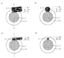
- the outer diameter of the conductive additive in the present invention is, for example, preferably in the range of 1 nm to 150 nm, more preferably in the range of 1 nm to 50 nm, and in the range of 1 nm to 10 nm. Further preferred. This is because if the outer diameter of the conductive auxiliary agent is too large, the conductive auxiliary agent is easily peeled from the coat layer, and if the outer diameter of the conductive auxiliary agent is too small, it is difficult to secure an electron conduction path in the coat layer. For example, when CNT is used as the conductive auxiliary agent, as shown in FIG.
- FIG. 2A when the outer diameter d of the conductive auxiliary agent 3 in the XX line is larger than the thickness t of the coat layer 2, FIG. As shown in b), since the conductive auxiliary agent 3 comes out of the coat layer 2, it is easy to secure an electron conduction path, but the conductive auxiliary agent 3 easily peels from the coat layer 2, while FIG. As shown in FIG. 2D, when the outer diameter d of the conductive auxiliary agent 3 in the YY line is smaller than the thickness t of the coat layer 2, the conductive auxiliary agent 3 is removed from the coat layer 2 as shown in FIG. Since it does not come out, it is difficult to secure an electron conduction path, but the conductive additive 3 is difficult to peel from the coat layer 2.
- 2B is a cross-sectional view taken along the line XX of FIG. 2A
- FIG. 2D is a cross-sectional view taken along the line YY of FIG. 2C.
- the electronic conductivity of the conductive additive in the present invention is, for example, preferably 1 S / cm or more, and more preferably 10 S / cm or more.
- the oxide solid electrolyte material in the present invention is generally stable because it has a lower reactivity with respect to the sulfide solid electrolyte material than the oxide active material.
- the oxide solid electrolyte material in the present invention is not particularly limited as long as it is an ion conductive oxide having a lower reactivity than the oxide active material with respect to the sulfide solid electrolyte material.
- the ion conductive oxide preferably includes a Li element, an A element, and an O element.
- the A is not particularly limited, and examples thereof include P, B, Si, Ge, Nb, Ti, and Zr.
- ion conductive oxides include Li 3 PO 4 , Li 3 BO 3 , Li 4 SiO 4 , Li 4 GeO 4 , LiNbO 3 , LiTiO 3 , Li 2 ZrO 3, and the like.
- the oxide solid electrolyte material may be a composite compound of the above-described ion conductive oxide. Examples of such a composite compound include Li 3 BO 3 —Li 4 SiO 4 , Li 3 PO 4. -Li 4 SiO 4 , Li 3 PO 4 -Li 4 GeO 4 and the like.
- the Li ion conductivity of the oxide solid electrolyte material is preferably, for example, 1 ⁇ 10 ⁇ 6 S / cm or more, and 1 ⁇ 10 ⁇ More preferably, it is 5 S / cm or more.
- the arrangement of the conductive auxiliary agent in the coat layer in the present invention is not particularly limited as long as the effect of the present invention can be exhibited.
- one end of the conductive auxiliary agent contacts the oxide active material. It is preferable that one end of the conductive auxiliary agent protrudes from the coat layer.
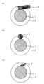
- the conductive auxiliary agent is fibrous, as shown in FIG. 3A, one side of the conductive auxiliary agent 3 contacts the oxide active material 1 and the other side of the conductive auxiliary agent 3 is coated.
- the conductive additive is granular, as shown in FIG. 3 (b)
- a part of the conductive additive 3 comes into contact with the oxide active material 1, and the conductive auxiliary agent is in a granular form.
- a mode in which a part of the auxiliary agent 3 comes out of the coating layer 2 may be used.
- the conductive auxiliary agent 3 in contact with the oxide active material 1 and the auxiliary agent 3 come out of the coating layer 2.
- the aspect which the connected conductive support agent 3 is connected by the some conductive support agent 3 may be sufficient.
- a conductive support agent is mixed with oxide solid electrolyte material, and is disperse
- the CNTs are basically present in the coat layer in a sleeping state, and a part of the CNTs protrudes from the coat layer, or a part of the CNTs touches the active material. .
- the content of the conductive additive in the coating layer is not particularly limited as long as it is within a range where the electronic conductivity of the coated active material can be improved.
- the ratio of the conductive assistant to the oxide solid electrolyte material is preferably in the range of 0.1% by weight to 20% by weight, and in the range of 1% by weight to 5% by weight. It is more preferable. This is because if the ratio of the conductive assistant to the oxide solid electrolyte material is too high, the conductive assistant usually has low ionic conductivity, so the coat layer may become a high resistance layer. This is because if the ratio of the conductive additive to the electrolyte material is too low, the electronic conductivity of the coated active material may not be sufficiently improved.
- the thickness of the coating layer is not particularly limited as long as it does not cause a reaction between the oxide active material and the sulfide solid electrolyte material and functions sufficiently as a coating layer. It is preferably in the range of 100 nm, more preferably in the range of 1 nm to 20 nm. This is because if the coat layer is too thin, the uncoated portion of the oxide active material may react with the sulfide solid electrolyte material. If the coat layer is too thick, the ionic conductivity and the electronic conductivity are reduced. Because there is a possibility. In addition, as a measuring method of the thickness of a coat layer, a transmission electron microscope (TEM) etc. can be mentioned, for example.
- TEM transmission electron microscope
- the coverage of the coating layer on the surface of the oxide active material is preferably high from the viewpoint of suppressing increase in interface resistance, specifically, preferably 90% or more, more preferably 95% or more. preferable.
- the coat layer may cover the entire surface of the oxide active material.
- TEM transmission electron microscope
- XPS X-ray photoelectron spectroscopy
- the coat layer in the present invention is preferably a film having no grain boundary. This is because it can be a coated active material having no grain boundary resistance.
- TEM transmission electron microscope
- the film-like coating layer having no grain boundary can be formed, for example, by a liquid phase method (wet method) such as a sol-gel method.
- wet method liquid phase method
- aggregation of a conductive support agent for example, CNT
- CNT conductive support agent
- the coating layer is formed by coating with a mixer mill.
- the solid electrolyte particles can be supported on the surface of the active material, but a film-like coating layer without grain boundaries cannot be formed, and the particulate solid electrolyte is not formed. It is thought that grain boundary resistance occurs because the coated layer is gathered.
- the oxide active material in this invention changes with kinds of the conductive ion of the all-solid-state battery in which the target electrode body is used. For example, when the electrode body of the present invention is used in an all-solid lithium secondary battery, the oxide active material occludes / releases Li ions.
- the oxide active material in the present invention usually reacts with a sulfide solid electrolyte material to form a high resistance layer. Formation of the high resistance layer can be confirmed by a transmission electron microscope (TEM), energy dispersive X-ray spectroscopy (EDX), or the like.
- TEM transmission electron microscope
- EDX energy dispersive X-ray spectroscopy
- the oxide active material in the present invention is not particularly limited as long as it can react with the sulfide solid electrolyte material to form a high resistance layer.
- M is preferably at least one selected from the group consisting of Co, Mn, Ni, V and Fe, and preferably at least one selected from the group consisting of Co, Ni and Mn. More preferred.
- an oxide active material specifically, a rock salt layer type active material such as LiCoO 2 , LiMnO 2 , LiNiO 2 , LiVO 2 , LiNi 1/3 Co 1/3 Mn 1/3 O 2 , LiMn Examples thereof include spinel active materials such as 2 O 4 and Li (Ni 0.5 Mn 1.5 ) O 4 .
- oxide active material other than the above-mentioned general formula Li x M y O z cited LiFePO 4, olivine type active material of LiMnPO 4 such, Li 2 FeSiO 4, Li 2 MnSiO Si -containing active material such as 4 be able to.
- Nb 2 O 5 , Li 4 Ti 5 O 12 , SiO, and the like can be used as the oxide active material used as the negative electrode active material of the all solid lithium battery.
- the oxide active material in the present invention may be used as a positive electrode active material or a negative electrode active material. This is because the positive electrode active material or the negative electrode active material is determined by the potential of the active material to be combined.
- the shape of the oxide active material in the present invention examples include a particle shape, and among them, a true spherical shape or an elliptical spherical shape is preferable.
- the oxide active material has a particle shape
- the average particle diameter (D 50 ) is preferably in the range of 0.1 ⁇ m to 50 ⁇ m, for example.
- Coated active material The content of the coated active material in the electrode body of the present invention is preferably in the range of 10% by weight to 99% by weight, for example, in the range of 20% by weight to 90% by weight. It is more preferable.
- the method for forming the coated active material will be described in detail in “C. Method for producing coated active material” described later.
- the sulfide solid electrolyte material in the present invention is in contact with the above-mentioned coated active material, and usually reacts with an oxide active material to form a high resistance layer. Formation of the high resistance layer can be confirmed by a transmission electron microscope (TEM), energy dispersive X-ray spectroscopy (EDX), or the like.
- TEM transmission electron microscope
- EDX energy dispersive X-ray spectroscopy
- the sulfide solid electrolyte material in the present invention is not particularly limited as long as it reacts with an oxide active material to form a high resistance layer.
- the electrode of the present invention is used in the all-solid-state lithium batteries
- the sulfide solid electrolyte material for example, Li 2 S-P 2 S 5, Li 2 S-P 2 S 5 -LiI, Li 2 S-P 2 S 5 —Li 2 O, Li 2 S—P 2 S 5 —Li 2 O—LiI, Li 2 S—SiS 2 , Li 2 S—SiS 2 —LiI, Li 2 S—SiS 2 —LiBr, Li 2 S—SiS 2 —LiCl, Li 2 S—SiS 2 —B 2 S 3 —LiI, Li 2 S—SiS 2 —P 2 S 5 —LiI, Li 2 S—B 2 S 3 , Li 2 S—P 2 S 5 -Z m S n (however
- the sulfide solid electrolyte material if it is made by using the raw material composition containing Li 2 S and P 2 S 5, the proportion of Li 2 S to the total of Li 2 S and P 2 S 5 is For example, it is preferably in the range of 70 mol% to 80 mol%, more preferably in the range of 72 mol% to 78 mol%, and still more preferably in the range of 74 mol% to 76 mol%. This is because a sulfide solid electrolyte material having an ortho composition or a composition in the vicinity thereof can be obtained, and a sulfide solid electrolyte material having high chemical stability can be obtained.
- ortho generally refers to one having the highest degree of hydration among oxo acids obtained by hydrating the same oxide.
- the crystal composition in which Li 2 S is added most in the sulfide is called the ortho composition.
- Li 2 S—P 2 S 5 system Li 3 PS 4 corresponds to the ortho composition.
- P 2 S 5 in the raw material composition, even when using the Al 2 S 3, or B 2 S 3, a preferred range is the same.
- Li 3 AlS 3 corresponds to the ortho composition
- Li 3 BS 3 corresponds to the ortho composition.
- the sulfide solid electrolyte material if it is made by using the raw material composition containing Li 2 S and SiS 2, the ratio of Li 2 S to the total of Li 2 S and SiS 2, for example, 60 mol% It is preferably in the range of ⁇ 72 mol%, more preferably in the range of 62 mol% to 70 mol%, and still more preferably in the range of 64 mol% to 68 mol%. This is because a sulfide solid electrolyte material having an ortho composition or a composition in the vicinity thereof can be obtained, and a sulfide solid electrolyte material having high chemical stability can be obtained. In the Li 2 S—SiS 2 system, Li 4 SiS 4 corresponds to the ortho composition.
- the preferred range is the same when GeS 2 is used instead of SiS 2 in the raw material composition.
- Li 4 GeS 4 corresponds to the ortho composition.
- the ratio of LiX is within a range of 1 mol% to 60 mol%, for example. It is preferably within a range of 5 mol% to 50 mol%, more preferably within a range of 10 mol% to 40 mol%.
- the sulfide solid electrolyte material may be sulfide glass, crystallized sulfide glass, or a crystalline material (material obtained by a solid phase method).
- the shape of the sulfide solid electrolyte material in the present invention examples include a particle shape, and among them, a true spherical shape or an elliptical spherical shape is preferable.
- the average particle size (D 50) is preferably 40 ⁇ m or less, more preferably 20 ⁇ m or less More preferably, it is 10 ⁇ m or less. This is because it becomes easy to improve the filling rate of the electrode body of the present invention.
- the average particle diameter is preferably 0.01 ⁇ m or more, and more preferably 0.1 ⁇ m or more.
- the said average particle diameter can be determined with a particle size distribution meter, for example.
- the sulfide solid electrolyte material is a Li ion conductor
- the Li ion conductivity at room temperature is preferably 1 ⁇ 10 ⁇ 5 S / cm or more, for example, and preferably 1 ⁇ 10 ⁇ 4 S / cm or more. It is more preferable that
- the content of the sulfide solid electrolyte material in the electrode body of the present invention is, for example, preferably in the range of 1% by weight to 90% by weight, and more preferably in the range of 10% by weight to 80% by weight. .
- Electrode Body has at least the above-described coated active material and sulfide solid electrolyte material, but may further have a binder and a conductive aid as necessary.
- the binder include fluorine-containing binders such as PTFE and PVDF.
- the conductive assistant include acetylene black, ketjen black, and carbon fiber.
- the thickness of the electrode body of the present invention varies depending on the type of the all-solid battery intended and the application of the electrode body, but is preferably in the range of 0.1 ⁇ m to 1000 ⁇ m, for example.
- the electrode body of the present invention is usually used for all solid state batteries.
- all-solid-state battery is described in “B. All-solid-state battery” which will be described later, description thereof is omitted here.
- the method etc. which compression-mold the composition containing the said coating active material and the said sulfide solid electrolyte material, etc. can be mentioned, for example.
- the all solid state battery of the present invention includes a positive electrode active material layer containing a positive electrode active material, a negative electrode active material layer containing a negative electrode active material, and a solid formed between the positive electrode active material layer and the negative electrode active material layer.
- the all-solid-state battery in which the electronic conductivity of the coated active material is improved and the reaction resistance is reduced can be obtained.
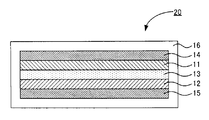
- FIG. 4 is a schematic cross-sectional view showing an example of the all solid state battery of the present invention.
- 4 includes a positive electrode active material layer 11, a negative electrode active material layer 12, a solid electrolyte layer 13 formed between the positive electrode active material layer 11 and the negative electrode active material layer 12, and a positive electrode active material. It has a positive electrode current collector 14 for collecting the material layer 11, a negative electrode current collector 15 for collecting the negative electrode active material layer 12, and a battery case 16 for housing these members.
- the all-solid-state battery 20 of the present invention is greatly characterized in that at least one of the positive electrode active material layer 11 and the negative electrode active material layer 12 is the electrode body described in the above “A. Electrode body”.
- the all solid state battery of the present invention will be described for each configuration.
- the positive electrode active material layer in the present invention is a layer containing at least a positive electrode active material, and may further contain at least one of a solid electrolyte material, a conductive additive and a binder as necessary.
- the positive electrode active material layer in the present invention is preferably the electrode body described in the above “A. Electrode body”. This is because the electron conductivity of the positive electrode active material layer is improved and the reaction resistance can be reduced.
- the negative electrode active material layer is the electrode body described above, the positive electrode active material layer may not be the electrode body described above.
- the positive electrode active material used for the positive electrode active material layer other than the electrode body described above a general positive electrode active material can be used.
- the content of the positive electrode active material in the positive electrode active material layer is preferably in the range of 10 wt% to 99 wt%, and more preferably in the range of 20 wt% to 90 wt%.
- the positive electrode active material layer preferably contains a solid electrolyte material. Examples of the solid electrolyte material used for the positive electrode active material layer include a sulfide solid electrolyte material and an oxide solid electrolyte material.
- the content of the solid electrolyte material in the positive electrode active material layer is, for example, preferably in the range of 1% by weight to 90% by weight, and more preferably in the range of 10% by weight to 80% by weight.
- the positive electrode active material layer may further contain a conductive auxiliary.
- the positive electrode active material layer may further contain a binder.
- the conductive auxiliary agent and the binder are the same as those described in the above “A. Electrode body”.
- the thickness of the positive electrode active material layer varies depending on the intended configuration of the all-solid battery, but is preferably in the range of 0.1 ⁇ m to 1000 ⁇ m, for example.
- the negative electrode active material layer in the present invention is a layer containing at least a negative electrode active material, and may further contain at least one of a solid electrolyte material, a conductive additive and a binder as necessary.
- the negative electrode active material layer in the present invention is preferably the electrode body described in the above “A. Electrode body”. This is because the electron conductivity of the negative electrode active material layer is improved and the reaction resistance can be reduced.
- the positive electrode active material layer is the electrode body described above, the negative electrode active material layer may not be the electrode body described above.
- Examples of the negative electrode active material used for the negative electrode active material layer other than the electrode body described above include a metal active material and a carbon active material.
- Examples of the metal active material include In, Al, Si, and Sn.
- examples of the carbon active material include graphite such as mesocarbon microbeads (MCMB) and highly oriented graphite (HOPG), and amorphous carbon such as hard carbon and soft carbon. Note that SiC or the like can also be used as the negative electrode active material.
- the content of the negative electrode active material in the negative electrode active material layer is, for example, preferably in the range of 10% by weight to 99% by weight, and more preferably in the range of 20% by weight to 90% by weight.
- the negative electrode active material layer preferably contains a solid electrolyte material.
- the content of the solid electrolyte material in the negative electrode active material layer is, for example, preferably in the range of 1% by weight to 90% by weight, and more preferably in the range of 10% by weight to 80% by weight.
- the conductive support agent and binder used for the said negative electrode active material layer it is the same as that of the case in the positive electrode active material layer mentioned above.
- the thickness of the negative electrode active material layer varies depending on the intended configuration of the all-solid battery, but is preferably in the range of 0.1 ⁇ m to 1000 ⁇ m, for example.
- the solid electrolyte layer in the present invention is a layer formed between the positive electrode active material layer and the negative electrode active material layer, and is a layer containing at least a solid electrolyte material.
- the solid electrolyte material is not particularly limited as long as it has ion conductivity, and examples thereof include a sulfide solid electrolyte material and an oxide solid electrolyte material. Among them, a sulfide solid electrolyte material Is preferred.
- the content of the solid electrolyte material in the solid electrolyte layer is preferably in the range of 10% by weight to 100% by weight, for example, and more preferably in the range of 50% by weight to 100% by weight.
- the solid electrolyte layer may contain a binder. Examples of the binder include fluorine-containing binders such as PTFE and PVDF.
- the thickness of the solid electrolyte layer is not particularly limited. For example, the thickness is preferably in the range of 0.1 ⁇ m to 1000 ⁇ m, and more preferably in the range of 0.1 ⁇ m to 300 ⁇ m.
- the all solid state battery of the present invention has at least the positive electrode active material layer, the negative electrode active material layer, and the solid electrolyte layer described above. Furthermore, it usually has a positive electrode current collector for collecting current of the positive electrode active material layer and a negative electrode current collector for collecting current of the negative electrode active material layer.
- the material for the positive electrode current collector include SUS, aluminum, nickel, iron, titanium, and carbon.
- examples of the material for the negative electrode current collector include SUS, copper, nickel, and carbon.
- the thickness and shape of the positive electrode current collector and the negative electrode current collector are preferably appropriately selected according to the use of the all solid state battery.
- the battery case of a general all-solid-state battery can be used for the battery case used for this invention. Examples of the battery case include a SUS battery case.
- All-solid battery Examples of the all-solid battery of the present invention include an all-solid lithium battery, an all-solid sodium battery, an all-solid magnesium battery, an all-solid calcium battery, and the like. Among these, an all-solid lithium battery is preferable. Further, the all solid state battery of the present invention may be a primary battery or a secondary battery, but among them, a secondary battery is preferable. This is because it can be repeatedly charged and discharged and is useful, for example, as a vehicle-mounted battery. Examples of the shape of the all solid state battery of the present invention include a coin type, a laminate type, a cylindrical type, and a square type.
- the manufacturing method of the all-solid-state battery of this invention will not be specifically limited if it is a method which can obtain the all-solid-state battery mentioned above, The method similar to the manufacturing method of a general all-solid-state battery is used. be able to.
- the method for producing a coated active material of the present invention comprises a coating layer formed by mixing an oxide solid electrolyte material precursor solution containing a raw material of an oxide solid electrolyte material and a conductive auxiliary agent dispersion containing a conductive auxiliary agent.
- a coating step for forming the film is a coating layer formed by mixing an oxide solid electrolyte material precursor solution containing a raw material of an oxide solid electrolyte material and a conductive auxiliary agent dispersion containing a conductive auxiliary agent.
- an increase in interfacial resistance can be suppressed by using a coating layer forming coating solution obtained by mixing an oxide solid electrolyte material precursor solution and a conductive auxiliary agent dispersion, and electron conductivity can be suppressed. It is possible to obtain a coated active material with improved Further, by forming the coat layer by a liquid phase method (wet method), a film-like coat layer having no grain boundary can be formed uniformly, and a coated active material having no grain boundary resistance can be obtained. . Furthermore, when forming a coat layer by a dry method, a fibrous conductive additive such as carbon nanotube (CNT) has a strong cohesive force, so it cannot be sufficiently dissociated in the coat layer and is not easily dispersed. In the present invention, since the coating layer is formed by a wet method, high dispersibility can be achieved even with a conductive additive having a strong cohesive force.
- CNT carbon nanotube
- FIG. 5 is a flowchart showing an example of the method for producing a coated active material of the present invention.
- an oxide solid electrolyte material precursor solution obtained by mixing a raw material of an oxide solid electrolyte material in a solvent, and a conductive assistant dispersion liquid obtained by mixing and dispersing a conductive additive in a solvent are prepared.
- a coating layer forming coating solution is prepared (preparation step).
- a coating layer for coating the surface of the oxide active material is formed by coating the oxide active material with a coating liquid for forming a coat layer using a rolling fluidized bed coating apparatus and drying the coating liquid.
- Coating process A coated active material is obtained.
- the manufacturing method of the coating active material of this invention is demonstrated for every process.
- the preparation step in the present invention is a coating layer forming coating comprising a mixture of an oxide solid electrolyte material precursor solution containing a raw material of an oxide solid electrolyte material and a conductive auxiliary agent dispersion containing a conductive auxiliary agent. This is a step of preparing a liquid.
- the coating layer forming coating solution prepared by this step is usually a sol-gel solution.
- the oxide solid electrolyte material precursor solution in the present invention contains a raw material for an oxide solid electrolyte material, and usually a raw material for an oxide solid electrolyte material is used as a solvent. Dissolved or dispersed. In addition, about an oxide solid electrolyte material, the thing similar to the oxide solid electrolyte material described in said "A. electrode body" can be mentioned.
- the raw material for the oxide solid electrolyte material in the present invention is not particularly limited as long as it can form a coating layer containing the oxide solid electrolyte material.
- a Li source compound and an A source compound can be used as a raw material for the oxide solid electrolyte material.
- A is not specifically limited, For example, P, B, Si, Ge, Nb, Ti, Zr etc. can be mentioned.
- the Li source compound include Li alkoxides such as ethoxy lithium and methoxy lithium, lithium acetate, and lithium hydroxide.
- the A source compound include A-containing alkoxide, acetate, hydroxide and the like.
- examples of the Nb source compound include Nb alkoxides such as pentaethoxyniobium and pentamethoxyniobium, niobium acetate, and niobium hydroxide.
- the solvent used in the oxide solid electrolyte material precursor solution in the present invention is not particularly limited as long as it does not degrade the raw material of the oxide solid electrolyte material, and examples thereof include ethanol. In addition, it is preferable that the said solvent is a thing with little water content.
- the ratio of the raw material of the oxide solid electrolyte material contained in the oxide solid electrolyte material precursor solution in the present invention is appropriately selected according to the composition of the coating layer of the target coating active material.
- the conductive auxiliary agent dispersion in the present invention contains a conductive auxiliary agent and is usually obtained by dispersing the conductive auxiliary agent in a solvent.
- description here is abbreviate
- the solvent used in the conductive auxiliary agent dispersion in the present invention is not particularly limited as long as the conductive auxiliary agent is not deteriorated, and examples thereof include ethanol. In addition, it is preferable that the said solvent is a thing with little water content.
- the method for dispersing the conductive additive in the solvent is not particularly limited as long as it can be highly dispersed, and examples thereof include ultrasonic dispersion.
- the proportion of the conductive auxiliary agent contained in the conductive auxiliary agent dispersion in the present invention is preferably selected as appropriate according to the composition of the coating layer of the target coating active material.
- the mixing ratio of the oxide solid electrolyte material precursor solution and the conductive auxiliary agent dispersion used in the coating layer forming coating liquid of the present invention is the target coating active material. It is preferable to select appropriately according to the composition of the coat layer possessed.
- the method for preparing the coating layer forming coating solution is not particularly limited, but the oxide solid electrolyte material precursor solution is added to the conductive auxiliary agent dispersion and sufficiently stirred and mixed. It is preferable.
- the coating step in the present invention is a step of forming a coat layer that covers the surface of the oxide active material by applying the coating liquid for forming the coat layer to the oxide active material and drying it. is there.
- the oxide active material is the same as that described in the above “A. Electrode body”, and the description thereof is omitted here.
- Examples of the method for applying the coating layer forming coating solution to the oxide active material include a rolling fluid coating method, a spray method, a dipping method, and a spray dryer method.
- a rolling fluid coating method is preferred. This is because a highly uniform coat layer can be obtained.
- the coating treatment for forming the coat layer is applied to the surface of the oxide active material, and then the drying treatment is performed.
- the solvent of the coating layer forming coating solution is volatilized to form a coating layer that covers the surface of the oxide active material.
- a coating process may be performed only once and may be performed in multiple times.
- the intake air temperature for the drying treatment is not particularly limited as long as it is a temperature at which the solvent can be volatilized. For example, it is preferably in the range of 30 ° C. to 100 ° C., and preferably 40 ° C. to 70 ° C. More preferably within the range. This is because if the intake air temperature is too low, the volatilization rate of the solvent becomes slow, and if the intake air temperature is too high, the coated active material may be deteriorated.
- heat treatment may be performed in a temperature range in which the oxide active material and the coating layer do not deteriorate.
- the solvent that can remain in the coat layer can be removed, and densification of the coat layer can be promoted.
- Coating active material The coating active material obtained by this invention is normally used for a battery. By using the coating active material, it is possible to obtain a battery with reduced reaction resistance while suppressing an increase in interface resistance between the oxide active material and another substance such as a sulfide solid electrolyte material.
- the present invention is not limited to the above embodiment.
- the above-described embodiment is an exemplification, and the present invention has substantially the same configuration as the technical idea described in the claims of the present invention, and any device that exhibits the same function and effect is the present invention. It is included in the technical scope of the invention.
- Example 10 Preparation of coating layer forming coating solution
- a mixed solution in which 0.34 g of carbon nanotubes (CNT, manufactured by Meijo Nanocarbon) with an average diameter of 1.4 nm was mixed with 600 g of dehydrated ethanol (manufactured by Wako Pure Chemical Industries, Ltd.) was subjected to dispersion treatment with an ultrasonic disperser, and a conductive additive. A dispersion was prepared.
- CNT carbon nanotubes
- the amount of CNT is 1 wt% with respect to the amount of the oxide solid electrolyte material, and a coating layer having a thickness of about 7 nm is formed on the active material surface.
- a LiNbO 3 raw material was charged with a LiNbO 3 raw material.
- the powder resistance of the coated active materials obtained in the examples and comparative examples was measured.
- the powder resistance was measured by using a resistivity meter (Mitsubishi Chemical Analytech, Loresta GP MCP-T610 type) as a single powder.
- the result is shown in FIG.
- the coated active material obtained in the example has a powder resistance value (volume resistivity) in a low surface pressure condition that is one digit lower than that of the coated active material obtained in the comparative example. It has been confirmed that the above is reduced. This is considered because CNT was added to the coat layer.
Landscapes
- Chemical & Material Sciences (AREA)
- General Chemical & Material Sciences (AREA)
- Chemical Kinetics & Catalysis (AREA)
- Electrochemistry (AREA)
- Composite Materials (AREA)
- General Physics & Mathematics (AREA)
- Condensed Matter Physics & Semiconductors (AREA)
- Inorganic Chemistry (AREA)
- Engineering & Computer Science (AREA)
- Manufacturing & Machinery (AREA)
- Physics & Mathematics (AREA)
- Battery Electrode And Active Subsutance (AREA)
- Secondary Cells (AREA)
- Primary Cells (AREA)
Abstract
Description
まず、本発明の電極体について説明する。本発明の電極体は、酸化物活物質、および上記酸化物活物質の表面を被覆し、酸化物固体電解質材料を含有するコート層を有する被覆活物質と、上記被覆活物質に接する硫化物固体電解質材料とを有する電極体であって、上記コート層が、さらに導電助剤を含有することを特徴とするものである。
以下、本発明の電極体について、構成ごとに説明する。
まず、本発明における被覆活物質について説明する。本発明における被覆活物質は、酸化物活物質、および上記酸化物活物質の表面を被覆し、酸化物固体電解質材料を含有するコート層を有するものである。
本発明におけるコート層は、酸化物活物質の表面を被覆し、酸化物固体電解質材料を含有するものである。また、本発明においては、上記コート層が、導電助剤を含有することを大きな特徴とする。
本発明における酸化物活物質は、目的とする電極体が用いられる全固体電池の伝導イオンの種類により異なるものである。例えば、本発明の電極体が全固体リチウム二次電池に用いられる場合、酸化物活物質は、Liイオンを吸蔵・放出する。また、本発明における酸化物活物質は、通常、硫化物固体電解質材料と反応して高抵抗層を形成するものである。高抵抗層の形成は、透過型電子顕微鏡(TEM)、エネルギー分散型X線分光法(EDX)等により確認することができる。
本発明の電極体における被覆活物質の含有量は、例えば、10重量%~99重量%の範囲内であることが好ましく、20重量%~90重量%の範囲内であることがより好ましい。なお、被覆活物質の形成方法については、後述する「C.被覆活物質の製造方法」で詳細に説明する。
次に、本発明における硫化物固体電解質材料について説明する。本発明における硫化物固体電解質材料は、上記被覆活物質と接するものであり、通常、酸化物活物質と反応して高抵抗層を形成するものである。高抵抗層の形成は、透過型電子顕微鏡(TEM)、エネルギー分散型X線分光法(EDX)等により確認することができる。
本発明の電極体は、上述した被覆活物質および硫化物固体電解質材料を少なくとも有するものであるが、必要に応じて、結着材および導電助剤をさらに有していても良い。結着材としては、例えば、PTFE、PVDF等のフッ素含有結着材等を挙げることができる。一方、導電助剤としては、例えば、アセチレンブラック、ケッチェンブラック、カーボンファイバー等を挙げることができる。また、本発明の電極体の厚さは、目的とする全固体電池の種類および電極体の用途によって異なるものであるが、例えば、0.1μm~1000μmの範囲内であることが好ましい。
次に、本発明の全固体電池について説明する。本発明の全固体電池は、正極活物質を含有する正極活物質層と、負極活物質を含有する負極活物質層と、上記正極活物質層および上記負極活物質層の間に形成された固体電解質層とを有する全固体電池であって、上記正極活物質層および上記負極活物質層の少なくとも一方が、上述した電極体であることを特徴とするものである。
以下、本発明の全固体電池について、構成ごとに説明する。
まず、本発明における正極活物質層について説明する。本発明における正極活物質層は、少なくとも正極活物質を含有する層であり、必要に応じて、固体電解質材料、導電助剤および結着材の少なくとも一つをさらに含有していても良い。
次に、本発明における負極活物質層について説明する。本発明における負極活物質層は、少なくとも負極活物質を含有する層であり、必要に応じて、固体電解質材料、導電助剤および結着材の少なくとも一つをさらに含有していても良い。
次に、本発明における固体電解質層について説明する。本発明における固体電解質層は、正極活物質層および負極活物質層の間に形成される層であり、少なくとも固体電解質材料を含有する層である。固体電解質材料としては、イオン伝導性を有するものであれば特に限定されるものではないが、例えば、硫化物固体電解質材料および酸化物固体電解質材料を挙げることができ、中でも、硫化物固体電解質材料が好ましい。
本発明の全固体電池は、上述した正極活物質層、負極活物質層および固体電解質層を少なくとも有するものである。さらに通常は、正極活物質層の集電を行う正極集電体、および負極活物質層の集電を行う負極集電体を有する。正極集電体の材料としては、例えば、SUS、アルミニウム、ニッケル、鉄、チタンおよびカーボン等を挙げることができる。一方、負極集電体の材料としては、例えば、SUS、銅、ニッケルおよびカーボン等を挙げることができる。また、正極集電体および負極集電体の厚さや形状等については、全固体電池の用途等に応じて適宜選択することが好ましい。また、本発明に用いられる電池ケースには、一般的な全固体電池の電池ケースを用いることができる。電池ケースとしては、例えば、SUS製電池ケース等を挙げることができる。
本発明の全固体電池の種類としては、全固体リチウム電池、全固体ナトリウム電池、全固体マグネシウム電池および全固体カルシウム電池等を挙げることができ、中でも、全固体リチウム電池が好ましい。また、本発明の全固体電池は、一次電池であっても良く、二次電池であっても良いが、中でも、二次電池であることが好ましい。繰り返し充放電でき、例えば、車載用電池として有用だからである。本発明の全固体電池の形状としては、例えば、コイン型、ラミネート型、円筒型および角型等を挙げることができる。また、本発明の全固体電池の製造方法は、上述した全固体電池を得ることができる方法であれば特に限定されるものではなく、一般的な全固体電池の製造方法と同様の方法を用いることができる。
次に、本発明の被覆活物質の製造方法について説明する。本発明の被覆活物質の製造方法は、酸化物固体電解質材料の原料を含有する酸化物固体電解質材料前駆体溶液、および、導電助剤を含有する導電助剤分散液を混合してなるコート層形成用塗工液を調製する調製工程と、酸化物活物質に対して、上記コート層形成用塗工液を塗工し、乾燥することにより、上記酸化物活物質の表面を被覆するコート層を形成する被覆工程とを有することを特徴とするものである。
以下、本発明の被覆活物質の製造方法について、工程ごとに説明する。
まず、本発明における調製工程について説明する。本発明における調製工程は、酸化物固体電解質材料の原料を含有する酸化物固体電解質材料前駆体溶液、および、導電助剤を含有する導電助剤分散液を混合してなるコート層形成用塗工液を調製する工程である。なお、本工程により調製されるコート層形成用塗工液は、通常、ゾルゲル液である。
本発明における酸化物固体電解質材料前駆体溶液は、酸化物固体電解質材料の原料を含有するものであり、通常、溶媒に酸化物固体電解質材料の原料を溶解または分散させてなるものである。なお、酸化物固体電解質材料については、上記「A.電極体」に記載した酸化物固体電解質材料と同様のものを挙げることができる。
本発明における導電助剤分散液は、導電助剤を含有するものであり、通常、溶媒に導電助剤を分散させてなるものである。なお、導電助剤については、上記「A.電極体」に記載した内容と同様であるので、ここでの説明は省略する。
本発明におけるコート層形成用塗工液に用いられる上記酸化物固体電解質材料前駆体溶液および上記導電助剤分散液の混合比は、目的とする被覆活物質が有するコート層の組成に応じて、適宜選択することが好ましい。また、上記コート層形成用塗工液の調製方法は、特に限定されるものではないが、上記導電助剤分散液中に上記酸化物固体電解質材料前駆体溶液を加え、十分に撹拌・混合することが好ましい。
次に、本発明における被覆工程について説明する。本発明における被覆工程は、酸化物活物質に対して、上記コート層形成用塗工液を塗工し、乾燥することにより、上記酸化物活物質の表面を被覆するコート層を形成する工程である。なお、酸化物活物質については、上記「A.電極体」に記載した内容と同様であるので、ここでの説明は省略する。
本発明により得られる被覆活物質は、通常、電池に用いられるものである。上記被覆活物質を用いることで、酸化物活物質と、例えば、硫化物固体電解質材料等の他の物質との界面抵抗の増加を抑制しつつ、反応抵抗を低減した電池を得ることができる。
(コート層形成用塗工液の調製)
まず、脱水エタノール(和光純薬工業製)600gに平均径1.4nmのカーボンナノチューブ(CNT、名城ナノカーボン製)0.34gを混合した混合液を超音波分散機で分散処理し、導電助剤分散液を作製した。
次に、脱水エタノール(和光純薬工業製)340gに、Li:Nb=1:1となるようにエトキシリチウム(C2H5OLi、高純度化学研究所製)10.83gおよびペンタエトキシニオブ((C2H5O)5Nb、高純度化学研究所製)66.27gを混合し、酸化物固体電解質材料前駆体溶液を作製した。
さらに、酸化物固体電解質材料前駆体溶液中に導電助剤分散液を加え、十分に撹拌・混合することにより、コート層形成用塗工液を調製した。なお、上記コート層形成用塗工液において、CNTの量は、酸化物固体電解質材料の量に対して1wt%となっており、活物質表面に厚さ7nm程度のコート層が形成されるように、LiNbO3原料を仕込んだ。
活物質(LiNi1/3Co1/3Mn1/3O2)500gを用いて、転動流動層コート装置(パウレック製)内で流動させ、上記コート層形成用塗工液を活物質表面に塗布した。その後、吸気温度50℃で乾燥することにより、活物質の表面を被覆するコート層を形成し、被覆活物質を得た。
導電助剤分散液を作製せず、脱水エタノールの量を500gに変更して作製した酸化物固体電解質材料前駆体溶液をコート層形成用塗工液としたこと以外は、実施例と同様にして被覆活物質を得た。
(TEM観察)
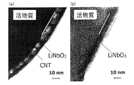
実施例および比較例で得られた被覆活物質のコート層断面の形態について、FIB加工を行ったサンプルをTEM(透過型電子顕微鏡)で観察した。その結果を図6(a)および(b)にそれぞれ示す。図6(a)に示されるように、実施例で得られた被覆活物質は、LiNbO3(酸化物固体電解質材料)を含有するコート層内にCNT(導電助剤)が取り込まれていることが確認された。一方、図6(b)に示されるように、比較例で得られた被覆活物質は、LiNbO3(酸化物固体電解質材料)を含有するコート層が確認された。
実施例および比較例で得られた被覆活物質の粉体抵抗測定を行った。粉体抵抗は、抵抗率計(三菱化学アナリテック製、ロレスタGP MCP-T610型)を用いて、粉体単体で測定した。その結果を図7に示す。図7に示されるように、実施例で得られた被覆活物質は、低面圧条件における粉体抵抗値(体積抵抗率)が、比較例で得られた被覆活物質に比べて、1桁以上低減していることが確認された。これは、コート層にCNTが添加されたためと考えられる。
2 … コート層
3 … 導電助剤
4 … 被覆活物質
5 … 硫化物固体電解質材料
10 … 電極体
11 … 正極活物質層
12 … 負極活物質層
13 … 固体電解質層
14 … 正極集電体
15 … 負極集電体
16 … 電池ケース
20 … 全固体電池
Claims (5)
- 酸化物活物質、および前記酸化物活物質の表面を被覆し、酸化物固体電解質材料を含有するコート層を有する被覆活物質と、前記被覆活物質に接する硫化物固体電解質材料とを有する電極体であって、
前記コート層が、導電助剤を含有することを特徴とする電極体。 - 前記コート層が、粒界のない膜状であることを特徴とする請求項1に記載の電極体。
- 前記導電助剤が、カーボンナノチューブであることを特徴とする請求項1または請求項2に記載の電極体。
- 正極活物質を含有する正極活物質層と、負極活物質を含有する負極活物質層と、前記正極活物質層および前記負極活物質層の間に形成された固体電解質層とを有する全固体電池であって、
前記正極活物質層および前記負極活物質層の少なくとも一方が、請求項1から請求項3までのいずれかの請求項に記載された電極体であることを特徴とする全固体電池。 - 酸化物固体電解質材料の原料を含有する酸化物固体電解質材料前駆体溶液、および、導電助剤を含有する導電助剤分散液を混合してなるコート層形成用塗工液を調製する調製工程と、
酸化物活物質に対して、前記コート層形成用塗工液を塗工し、乾燥することにより、前記酸化物活物質の表面を被覆するコート層を形成する被覆工程と
を有することを特徴とする被覆活物質の製造方法。
Priority Applications (4)
| Application Number | Priority Date | Filing Date | Title |
|---|---|---|---|
| JP2013514870A JP5979138B2 (ja) | 2011-05-13 | 2011-05-13 | 電極体、全固体電池および被覆活物質の製造方法 |
| US14/111,283 US9461303B2 (en) | 2011-05-13 | 2011-05-13 | Electrode body, all solid state battery, and method for producing coated active material |
| CN201180070635.3A CN103503202B (zh) | 2011-05-13 | 2011-05-13 | 电极体、全固体电池及被覆活性物质的制造方法 |
| PCT/JP2011/061082 WO2012157046A1 (ja) | 2011-05-13 | 2011-05-13 | 電極体、全固体電池および被覆活物質の製造方法 |
Applications Claiming Priority (1)
| Application Number | Priority Date | Filing Date | Title |
|---|---|---|---|
| PCT/JP2011/061082 WO2012157046A1 (ja) | 2011-05-13 | 2011-05-13 | 電極体、全固体電池および被覆活物質の製造方法 |
Publications (1)
| Publication Number | Publication Date |
|---|---|
| WO2012157046A1 true WO2012157046A1 (ja) | 2012-11-22 |
Family
ID=47176416
Family Applications (1)
| Application Number | Title | Priority Date | Filing Date |
|---|---|---|---|
| PCT/JP2011/061082 Ceased WO2012157046A1 (ja) | 2011-05-13 | 2011-05-13 | 電極体、全固体電池および被覆活物質の製造方法 |
Country Status (4)
| Country | Link |
|---|---|
| US (1) | US9461303B2 (ja) |
| JP (1) | JP5979138B2 (ja) |
| CN (1) | CN103503202B (ja) |
| WO (1) | WO2012157046A1 (ja) |
Cited By (24)
| Publication number | Priority date | Publication date | Assignee | Title |
|---|---|---|---|---|
| US20150243990A1 (en) * | 2014-02-24 | 2015-08-27 | Korea Institute Of Science And Technology | Cathode active material for sodium secondary battery, method for preparing the same and sodium secondary battery employing the same |
| CN104969386A (zh) * | 2013-02-08 | 2015-10-07 | 丰田自动车株式会社 | 复合活性物质、复合活性物质的制造方法和包含复合活性物质的锂二次电池 |
| JP2015216101A (ja) * | 2014-05-08 | 2015-12-03 | 現代自動車株式会社Hyundaimotor Company | 全固体バッテリーの電極構造 |
| US9887417B2 (en) | 2012-06-29 | 2018-02-06 | Toyota Jidosha Kabushiki Kaisha | Composite active material, solid state battery and method for producing composite active material |
| WO2018038037A1 (ja) * | 2016-08-22 | 2018-03-01 | 公立大学法人大阪府立大学 | 全固体二次電池用の複合正極活物質、その製造方法、正極及び全固体二次電池 |
| JP2018206537A (ja) * | 2017-05-31 | 2018-12-27 | トヨタ自動車株式会社 | 全固体電池 |
| JPWO2018047946A1 (ja) * | 2016-09-12 | 2019-06-24 | 富士フイルム株式会社 | 電極層材、全固体二次電池電極用シートおよび全固体二次電池ならびに全固体二次電池用電極シートおよび全固体二次電池の製造方法 |
| JP2019179669A (ja) * | 2018-03-30 | 2019-10-17 | Fdk株式会社 | 全固体電池の製造方法および全固体電池 |
| WO2020105695A1 (ja) * | 2018-11-21 | 2020-05-28 | 積水化学工業株式会社 | 全固体電池用活物質、全固体電池用電極及び全固体電池 |
| US10714743B2 (en) | 2017-03-06 | 2020-07-14 | Lg Chem, Ltd. | Method for manufacturing electrode including polymer electrolyte and electrode obtained thereby |
| WO2020203545A1 (ja) * | 2019-03-29 | 2020-10-08 | 富士フイルム株式会社 | 複合電極活物質、電極用組成物、全固体二次電池用電極シート及び全固体二次電池、並びに、複合電極活物質、全固体二次電池用電極シート及び全固体二次電池の製造方法 |
| US10868296B2 (en) | 2017-03-16 | 2020-12-15 | Lg Chem, Ltd. | Method for manufacturing electrode including polymer electrolyte and electrode obtained thereby |
| WO2020261600A1 (ja) * | 2019-06-24 | 2020-12-30 | Jx金属株式会社 | 全固体リチウムイオン電池用正極活物質、全固体リチウムイオン電池用正極、全固体リチウムイオン電池、及び全固体リチウムイオン電池用正極活物質の製造方法 |
| JP2021097008A (ja) * | 2019-12-19 | 2021-06-24 | 本田技研工業株式会社 | 電極材料製造方法及び電極材料 |
| JP2021118179A (ja) * | 2020-01-24 | 2021-08-10 | トヨタ自動車株式会社 | 正極材料、非水電解質二次電池、および、正極材料の製造方法 |
| JP2022510196A (ja) * | 2018-12-05 | 2022-01-26 | ロベルト・ボッシュ・ゲゼルシャフト・ミト・ベシュレンクテル・ハフツング | 電気化学セルのための前駆体材料を製造する方法 |
| WO2022168994A1 (ja) * | 2021-02-05 | 2022-08-11 | 株式会社村田製作所 | 二次電池 |
| JP2022146719A (ja) * | 2021-03-22 | 2022-10-05 | Jx金属株式会社 | 全固体リチウムイオン電池用正極活物質、全固体リチウムイオン電池用正極、全固体リチウムイオン電池及び全固体リチウムイオン電池用正極活物質の製造方法 |
| JP2023049448A (ja) * | 2021-09-29 | 2023-04-10 | パナソニックIpマネジメント株式会社 | 全固体電池およびその製造方法 |
| JP2023530031A (ja) * | 2020-06-19 | 2023-07-12 | ランシー ジーダ アドバンスド マテリアルズ カンパニー リミテッド | リチウム二次電池用のシリコン炭素複合材料及びその製造方法 |
| JP2024503415A (ja) * | 2021-08-31 | 2024-01-25 | エルジー エナジー ソリューション リミテッド | 全固体電池用電極 |
| JP2024072202A (ja) * | 2022-11-15 | 2024-05-27 | トヨタ自動車株式会社 | 正極材料、固体電池、正極材料の製造方法及び固体電池の製造方法 |
| US12142760B2 (en) | 2020-09-01 | 2024-11-12 | Hyundai Motor Company | Cathode active material for all-solid-state battery comprising coating layer including ternary oxide and method of manufacturing same |
| WO2024237045A1 (ja) * | 2023-05-16 | 2024-11-21 | パナソニックホールディングス株式会社 | 正極材料、正極、および電池 |
Families Citing this family (15)
| Publication number | Priority date | Publication date | Assignee | Title |
|---|---|---|---|---|
| KR20140053451A (ko) * | 2012-10-25 | 2014-05-08 | 삼성에스디아이 주식회사 | 복합양극활물질, 그 제조방법 및 이를 채용한 양극과 리튬전지 |
| JP6098568B2 (ja) * | 2014-04-04 | 2017-03-22 | トヨタ自動車株式会社 | 活物質粉体及びその製造方法 |
| KR20160128670A (ko) * | 2015-04-29 | 2016-11-08 | 현대자동차주식회사 | 고체 전해질 및 이를 포함하는 전고체 전지 |
| CN105355871B (zh) * | 2015-10-26 | 2018-07-17 | 江西赣锋电池科技有限公司 | 一种复合电极材料、其制备方法和全固态锂电池 |
| JP6418145B2 (ja) * | 2015-12-07 | 2018-11-07 | トヨタ自動車株式会社 | 複合固体電解質 |
| CN107768612B (zh) * | 2016-08-23 | 2022-10-14 | 松下知识产权经营株式会社 | 电极材料和电池 |
| KR102006726B1 (ko) | 2016-10-05 | 2019-08-02 | 주식회사 엘지화학 | 이차전지용 양극활물질 및 이를 포함하는 이차전지 |
| WO2018123322A1 (ja) * | 2016-12-29 | 2018-07-05 | 株式会社 村田製作所 | 負極活物質、負極、電池、電池パック、電子機器、電動車両、蓄電装置および電力システム |
| DE102017204852A1 (de) | 2017-03-22 | 2018-09-27 | Robert Bosch Gmbh | Lithium-Zellen-Kathode mit unterschiedlichen sulfidischen Lithiumionenleitern |
| US11527754B2 (en) * | 2017-09-29 | 2022-12-13 | Robert Bosch Gmbh | Solid composite electrode with coated materials |
| KR102552140B1 (ko) * | 2017-10-13 | 2023-07-05 | 현대자동차주식회사 | 전고체 전지용 전극의 제조 방법 |
| KR20210111949A (ko) * | 2020-03-03 | 2021-09-14 | 삼성에스디아이 주식회사 | 양극 및 이를 포함하는 전고체 이차전지, 및 전고체 이차전지의 제조 방법 |
| CN111816811A (zh) * | 2020-07-22 | 2020-10-23 | 平潭诚信智创科技有限公司 | 一种固态电池组及其控制方法 |
| JP2022128083A (ja) * | 2021-02-22 | 2022-09-01 | セイコーエプソン株式会社 | 前駆体溶液、前駆体粉末、電極の製造方法および電極 |
| KR102952948B1 (ko) * | 2022-05-31 | 2026-04-14 | 주식회사 엘지에너지솔루션 | 전고체 전지용 양극, 이의 제조 방법 및 상기 양극을 포함하는 전고체 전지 |
Citations (6)
| Publication number | Priority date | Publication date | Assignee | Title |
|---|---|---|---|---|
| JP2001273928A (ja) * | 2000-03-27 | 2001-10-05 | Osaka Prefecture | リチウム系二次電池及びその製造方法 |
| JP2003059492A (ja) * | 2001-08-17 | 2003-02-28 | Matsushita Electric Ind Co Ltd | リチウム二次電池およびその製造方法 |
| JP2003173770A (ja) * | 2001-12-04 | 2003-06-20 | Japan Storage Battery Co Ltd | 非水電解質電池および非水電解質電池の製造法 |
| JP2006107963A (ja) * | 2004-10-06 | 2006-04-20 | Nissan Motor Co Ltd | バイポーラ電池 |
| JP2009193940A (ja) * | 2008-02-18 | 2009-08-27 | Toyota Motor Corp | 電極体及びその製造方法、並びに、リチウムイオン二次電池 |
| JP2010225309A (ja) * | 2009-03-19 | 2010-10-07 | Toyota Motor Corp | 正極活物質材料の製造方法 |
Family Cites Families (11)
| Publication number | Priority date | Publication date | Assignee | Title |
|---|---|---|---|---|
| US4021255A (en) * | 1972-01-31 | 1977-05-03 | Kabushiki Kaisha Toyota Chuo Kenkyusho | Sintered beta-alumina article permeable to sodium and potassium ions and methods for producing same |
| JP4061586B2 (ja) | 2003-04-11 | 2008-03-19 | ソニー株式会社 | 非水電解質二次電池用正極活物質及びそれを用いた非水電解質二次電池 |
| US7364793B2 (en) * | 2004-09-24 | 2008-04-29 | Lg Chem, Ltd. | Powdered lithium transition metal oxide having doped interface layer and outer layer and method for preparation of the same |
| US7993782B2 (en) | 2005-07-01 | 2011-08-09 | National Institute For Materials Science | All-solid lithium battery |
| JP2009164104A (ja) * | 2007-09-06 | 2009-07-23 | Canon Inc | 負極用電極材料、その製造方法ならびに該材料を用いた電極構造体及び蓄電デバイス |
| JP5288816B2 (ja) | 2008-01-31 | 2013-09-11 | 株式会社オハラ | 固体電池 |
| JP5120272B2 (ja) | 2008-09-11 | 2013-01-16 | トヨタ自動車株式会社 | 硫化物系固体電解質 |
| EP2375477B1 (en) * | 2009-01-06 | 2016-12-21 | LG Chem, Ltd. | Positive electrode active material for lithium secondary battery |
| US20100216030A1 (en) * | 2009-02-20 | 2010-08-26 | Samsung Electronics Co., Ltd. | Positive electrode for all-solid secondary battery and all-solid secondary battery employing same |
| WO2010107084A1 (ja) * | 2009-03-18 | 2010-09-23 | 株式会社三徳 | 全固体リチウム電池 |
| US20120052383A1 (en) * | 2009-05-27 | 2012-03-01 | Sumitomo Electric Industries Ltd | Positive-electrode member and method for producing the same |
-
2011
- 2011-05-13 WO PCT/JP2011/061082 patent/WO2012157046A1/ja not_active Ceased
- 2011-05-13 US US14/111,283 patent/US9461303B2/en active Active
- 2011-05-13 JP JP2013514870A patent/JP5979138B2/ja active Active
- 2011-05-13 CN CN201180070635.3A patent/CN103503202B/zh active Active
Patent Citations (6)
| Publication number | Priority date | Publication date | Assignee | Title |
|---|---|---|---|---|
| JP2001273928A (ja) * | 2000-03-27 | 2001-10-05 | Osaka Prefecture | リチウム系二次電池及びその製造方法 |
| JP2003059492A (ja) * | 2001-08-17 | 2003-02-28 | Matsushita Electric Ind Co Ltd | リチウム二次電池およびその製造方法 |
| JP2003173770A (ja) * | 2001-12-04 | 2003-06-20 | Japan Storage Battery Co Ltd | 非水電解質電池および非水電解質電池の製造法 |
| JP2006107963A (ja) * | 2004-10-06 | 2006-04-20 | Nissan Motor Co Ltd | バイポーラ電池 |
| JP2009193940A (ja) * | 2008-02-18 | 2009-08-27 | Toyota Motor Corp | 電極体及びその製造方法、並びに、リチウムイオン二次電池 |
| JP2010225309A (ja) * | 2009-03-19 | 2010-10-07 | Toyota Motor Corp | 正極活物質材料の製造方法 |
Cited By (44)
| Publication number | Priority date | Publication date | Assignee | Title |
|---|---|---|---|---|
| US9887417B2 (en) | 2012-06-29 | 2018-02-06 | Toyota Jidosha Kabushiki Kaisha | Composite active material, solid state battery and method for producing composite active material |
| CN104969386A (zh) * | 2013-02-08 | 2015-10-07 | 丰田自动车株式会社 | 复合活性物质、复合活性物质的制造方法和包含复合活性物质的锂二次电池 |
| CN104969386B (zh) * | 2013-02-08 | 2017-04-19 | 丰田自动车株式会社 | 复合活性物质、复合活性物质的制造方法和包含复合活性物质的锂二次电池 |
| US20150243990A1 (en) * | 2014-02-24 | 2015-08-27 | Korea Institute Of Science And Technology | Cathode active material for sodium secondary battery, method for preparing the same and sodium secondary battery employing the same |
| JP2015216101A (ja) * | 2014-05-08 | 2015-12-03 | 現代自動車株式会社Hyundaimotor Company | 全固体バッテリーの電極構造 |
| WO2018038037A1 (ja) * | 2016-08-22 | 2018-03-01 | 公立大学法人大阪府立大学 | 全固体二次電池用の複合正極活物質、その製造方法、正極及び全固体二次電池 |
| JP7049665B2 (ja) | 2016-08-22 | 2022-04-07 | 公立大学法人大阪 | 全固体二次電池用の複合正極活物質、その製造方法、正極及び全固体二次電池 |
| JPWO2018038037A1 (ja) * | 2016-08-22 | 2019-06-20 | 公立大学法人大阪府立大学 | 全固体二次電池用の複合正極活物質、その製造方法、正極及び全固体二次電池 |
| US10840507B2 (en) | 2016-08-22 | 2020-11-17 | Osaka Prefecture University Public Corporation | Composite positive electrode active material for all-solid-state secondary battery, method for manufacturing same, positive electrode, and all-solid-state secondary battery |
| JPWO2018047946A1 (ja) * | 2016-09-12 | 2019-06-24 | 富士フイルム株式会社 | 電極層材、全固体二次電池電極用シートおよび全固体二次電池ならびに全固体二次電池用電極シートおよび全固体二次電池の製造方法 |
| US10714743B2 (en) | 2017-03-06 | 2020-07-14 | Lg Chem, Ltd. | Method for manufacturing electrode including polymer electrolyte and electrode obtained thereby |
| US10868296B2 (en) | 2017-03-16 | 2020-12-15 | Lg Chem, Ltd. | Method for manufacturing electrode including polymer electrolyte and electrode obtained thereby |
| JP2018206537A (ja) * | 2017-05-31 | 2018-12-27 | トヨタ自動車株式会社 | 全固体電池 |
| JP2019179669A (ja) * | 2018-03-30 | 2019-10-17 | Fdk株式会社 | 全固体電池の製造方法および全固体電池 |
| JP7122139B2 (ja) | 2018-03-30 | 2022-08-19 | Fdk株式会社 | 全固体電池の製造方法および全固体電池 |
| JP7397788B2 (ja) | 2018-11-21 | 2023-12-13 | 積水化学工業株式会社 | 全固体電池用活物質、全固体電池用電極及び全固体電池 |
| WO2020105695A1 (ja) * | 2018-11-21 | 2020-05-28 | 積水化学工業株式会社 | 全固体電池用活物質、全固体電池用電極及び全固体電池 |
| JPWO2020105695A1 (ja) * | 2018-11-21 | 2021-10-07 | 積水化学工業株式会社 | 全固体電池用活物質、全固体電池用電極及び全固体電池 |
| US11901547B2 (en) | 2018-12-05 | 2024-02-13 | Robert Bosch Gmbh | Method for producing a precursor material for an electrochemical cell |
| JP2022510196A (ja) * | 2018-12-05 | 2022-01-26 | ロベルト・ボッシュ・ゲゼルシャフト・ミト・ベシュレンクテル・ハフツング | 電気化学セルのための前駆体材料を製造する方法 |
| JP7350856B2 (ja) | 2018-12-05 | 2023-09-26 | ロベルト・ボッシュ・ゲゼルシャフト・ミト・ベシュレンクテル・ハフツング | 電気化学セルのための前駆体材料を製造する方法 |
| JPWO2020203545A1 (ja) * | 2019-03-29 | 2021-10-14 | 富士フイルム株式会社 | 複合電極活物質、電極用組成物、全固体二次電池用電極シート及び全固体二次電池、並びに、複合電極活物質、全固体二次電池用電極シート及び全固体二次電池の製造方法 |
| JP7061728B2 (ja) | 2019-03-29 | 2022-04-28 | 富士フイルム株式会社 | 複合電極活物質、電極用組成物、全固体二次電池用電極シート及び全固体二次電池、並びに、複合電極活物質、全固体二次電池用電極シート及び全固体二次電池の製造方法 |
| WO2020203545A1 (ja) * | 2019-03-29 | 2020-10-08 | 富士フイルム株式会社 | 複合電極活物質、電極用組成物、全固体二次電池用電極シート及び全固体二次電池、並びに、複合電極活物質、全固体二次電池用電極シート及び全固体二次電池の製造方法 |
| JP2021002504A (ja) * | 2019-06-24 | 2021-01-07 | Jx金属株式会社 | 全固体リチウムイオン電池用正極活物質、全固体リチウムイオン電池用正極、全固体リチウムイオン電池、及び全固体リチウムイオン電池用正極活物質の製造方法 |
| WO2020261600A1 (ja) * | 2019-06-24 | 2020-12-30 | Jx金属株式会社 | 全固体リチウムイオン電池用正極活物質、全固体リチウムイオン電池用正極、全固体リチウムイオン電池、及び全固体リチウムイオン電池用正極活物質の製造方法 |
| JP2021097008A (ja) * | 2019-12-19 | 2021-06-24 | 本田技研工業株式会社 | 電極材料製造方法及び電極材料 |
| US11705551B2 (en) | 2019-12-19 | 2023-07-18 | Honda Motor Co., Ltd. | Method for manufacturing electrode material |
| JP2021118179A (ja) * | 2020-01-24 | 2021-08-10 | トヨタ自動車株式会社 | 正極材料、非水電解質二次電池、および、正極材料の製造方法 |
| JP7597589B2 (ja) | 2020-01-24 | 2024-12-10 | トヨタ自動車株式会社 | 正極材料、非水電解質二次電池、および、正極材料の製造方法 |
| JP2023530031A (ja) * | 2020-06-19 | 2023-07-12 | ランシー ジーダ アドバンスド マテリアルズ カンパニー リミテッド | リチウム二次電池用のシリコン炭素複合材料及びその製造方法 |
| JP7531002B2 (ja) | 2020-06-19 | 2024-08-08 | ランシー ジーダ アドバンスド マテリアルズ カンパニー リミテッド | リチウム二次電池用のシリコン炭素複合材料及びその製造方法 |
| US12142760B2 (en) | 2020-09-01 | 2024-11-12 | Hyundai Motor Company | Cathode active material for all-solid-state battery comprising coating layer including ternary oxide and method of manufacturing same |
| JPWO2022168994A1 (ja) * | 2021-02-05 | 2022-08-11 | ||
| JP7771993B2 (ja) | 2021-02-05 | 2025-11-18 | 株式会社村田製作所 | 二次電池 |
| WO2022168994A1 (ja) * | 2021-02-05 | 2022-08-11 | 株式会社村田製作所 | 二次電池 |
| JP2022146719A (ja) * | 2021-03-22 | 2022-10-05 | Jx金属株式会社 | 全固体リチウムイオン電池用正極活物質、全固体リチウムイオン電池用正極、全固体リチウムイオン電池及び全固体リチウムイオン電池用正極活物質の製造方法 |
| JP7581102B2 (ja) | 2021-03-22 | 2024-11-12 | Jx金属株式会社 | 全固体リチウムイオン電池用正極活物質、全固体リチウムイオン電池用正極、全固体リチウムイオン電池及び全固体リチウムイオン電池用正極活物質の製造方法 |
| JP2024503415A (ja) * | 2021-08-31 | 2024-01-25 | エルジー エナジー ソリューション リミテッド | 全固体電池用電極 |
| JP7673207B2 (ja) | 2021-08-31 | 2025-05-08 | エルジー エナジー ソリューション リミテッド | 全固体電池用電極 |
| JP2023049448A (ja) * | 2021-09-29 | 2023-04-10 | パナソニックIpマネジメント株式会社 | 全固体電池およびその製造方法 |
| JP2024072202A (ja) * | 2022-11-15 | 2024-05-27 | トヨタ自動車株式会社 | 正極材料、固体電池、正極材料の製造方法及び固体電池の製造方法 |
| JP7719048B2 (ja) | 2022-11-15 | 2025-08-05 | トヨタ自動車株式会社 | 正極材料、固体電池、正極材料の製造方法及び固体電池の製造方法 |
| WO2024237045A1 (ja) * | 2023-05-16 | 2024-11-21 | パナソニックホールディングス株式会社 | 正極材料、正極、および電池 |
Also Published As
| Publication number | Publication date |
|---|---|
| JP5979138B2 (ja) | 2016-08-24 |
| US9461303B2 (en) | 2016-10-04 |
| US20140057180A1 (en) | 2014-02-27 |
| JPWO2012157046A1 (ja) | 2014-07-31 |
| CN103503202B (zh) | 2015-11-25 |
| CN103503202A (zh) | 2014-01-08 |
Similar Documents
| Publication | Publication Date | Title |
|---|---|---|
| JP5979138B2 (ja) | 電極体、全固体電池および被覆活物質の製造方法 | |
| Zhu et al. | Designed nanoarchitectures by electrostatic spray deposition for energy storage | |
| CN103534845B (zh) | 被覆活性物质及锂固体电池 | |
| JP6936959B2 (ja) | 正極合材、正極活物質層、全固体電池および正極活物質層の製造方法 | |
| JP6034265B2 (ja) | 活物質複合粉体及びリチウム電池並びにその製造方法 | |
| JP5500158B2 (ja) | 固体電池用電極の製造方法 | |
| CN103975466B (zh) | 正极活性物质材料、正极活性物质层、全固体电池以及正极活性物质材料的制造方法 | |
| WO2019243614A1 (en) | Electrode active materials and method for their manufacture | |
| JP6536302B2 (ja) | 被覆負極活物質 | |
| TW202030913A (zh) | 全固體電池用活性物質、全固體電池用電極及全固體電池 | |
| CN106410129A (zh) | 负极混合材料和全固体电池 | |
| CN103518283A (zh) | 锂固体电池 | |
| CN114824188B (zh) | 正极活性物质层形成用材料和使用该正极活性物质层形成用材料的非水电解质二次电池 | |
| CN108987792A (zh) | 全固体电池 | |
| JP2021172544A (ja) | 複合材料、その製造方法および全固体型リチウムイオン二次電池 | |
| JP2024154502A (ja) | 電極の製造方法 | |
| JP7582135B2 (ja) | 被覆負極活物質および全固体電池 | |
| JP6766739B2 (ja) | 全固体電池 | |
| CN114068913A (zh) | 全固体电池 | |
| JP2023100077A (ja) | 電極層 | |
| Lin et al. | Metal oxide-coated graphite composites as high-performance anode materials for lithium-ion batteries | |
| JP2017041392A (ja) | 全固体電池 | |
| JP2021172545A (ja) | 複合材料、その製造方法および全固体型リチウムイオン二次電池 | |
| US20250293260A1 (en) | Electrode mixture, electrode layer, and battery | |
| JP2024166679A (ja) | 電極の製造方法 |
Legal Events
| Date | Code | Title | Description |
|---|---|---|---|
| 121 | Ep: the epo has been informed by wipo that ep was designated in this application |
Ref document number: 11865650 Country of ref document: EP Kind code of ref document: A1 |
|
| ENP | Entry into the national phase |
Ref document number: 2013514870 Country of ref document: JP Kind code of ref document: A |
|
| WWE | Wipo information: entry into national phase |
Ref document number: 14111283 Country of ref document: US |
|
| NENP | Non-entry into the national phase |
Ref country code: DE |
|
| 122 | Ep: pct application non-entry in european phase |
Ref document number: 11865650 Country of ref document: EP Kind code of ref document: A1 |