WO2012127835A1 - 電子写真用導電性部材 - Google Patents
電子写真用導電性部材 Download PDFInfo
- Publication number
- WO2012127835A1 WO2012127835A1 PCT/JP2012/001851 JP2012001851W WO2012127835A1 WO 2012127835 A1 WO2012127835 A1 WO 2012127835A1 JP 2012001851 W JP2012001851 W JP 2012001851W WO 2012127835 A1 WO2012127835 A1 WO 2012127835A1
- Authority
- WO
- WIPO (PCT)
- Prior art keywords
- conductive
- resin
- ion
- layer
- conductive layer
- Prior art date
- Legal status (The legal status is an assumption and is not a legal conclusion. Google has not performed a legal analysis and makes no representation as to the accuracy of the status listed.)
- Ceased
Links
Images


Classifications
-
- G—PHYSICS
- G03—PHOTOGRAPHY; CINEMATOGRAPHY; ANALOGOUS TECHNIQUES USING WAVES OTHER THAN OPTICAL WAVES; ELECTROGRAPHY; HOLOGRAPHY
- G03G—ELECTROGRAPHY; ELECTROPHOTOGRAPHY; MAGNETOGRAPHY
- G03G15/00—Apparatus for electrographic processes using a charge pattern
- G03G15/02—Apparatus for electrographic processes using a charge pattern for laying down a uniform charge, e.g. for sensitising; Corona discharge devices
- G03G15/0208—Apparatus for electrographic processes using a charge pattern for laying down a uniform charge, e.g. for sensitising; Corona discharge devices by contact, friction or induction, e.g. liquid charging apparatus
- G03G15/0216—Apparatus for electrographic processes using a charge pattern for laying down a uniform charge, e.g. for sensitising; Corona discharge devices by contact, friction or induction, e.g. liquid charging apparatus by bringing a charging member into contact with the member to be charged, e.g. roller, brush chargers
- G03G15/0233—Structure, details of the charging member, e.g. chemical composition, surface properties
-
- F—MECHANICAL ENGINEERING; LIGHTING; HEATING; WEAPONS; BLASTING
- F16—ENGINEERING ELEMENTS AND UNITS; GENERAL MEASURES FOR PRODUCING AND MAINTAINING EFFECTIVE FUNCTIONING OF MACHINES OR INSTALLATIONS; THERMAL INSULATION IN GENERAL
- F16C—SHAFTS; FLEXIBLE SHAFTS; ELEMENTS OR CRANKSHAFT MECHANISMS; ROTARY BODIES OTHER THAN GEARING ELEMENTS; BEARINGS
- F16C13/00—Rolls, drums, discs, or the like; Bearings or mountings therefor
-
- G—PHYSICS
- G03—PHOTOGRAPHY; CINEMATOGRAPHY; ANALOGOUS TECHNIQUES USING WAVES OTHER THAN OPTICAL WAVES; ELECTROGRAPHY; HOLOGRAPHY
- G03G—ELECTROGRAPHY; ELECTROPHOTOGRAPHY; MAGNETOGRAPHY
- G03G15/00—Apparatus for electrographic processes using a charge pattern
- G03G15/06—Apparatus for electrographic processes using a charge pattern for developing
- G03G15/08—Apparatus for electrographic processes using a charge pattern for developing using a solid developer, e.g. powder developer
- G03G15/0806—Apparatus for electrographic processes using a charge pattern for developing using a solid developer, e.g. powder developer on a donor element, e.g. belt, roller
- G03G15/0818—Apparatus for electrographic processes using a charge pattern for developing using a solid developer, e.g. powder developer on a donor element, e.g. belt, roller characterised by the structure of the donor member, e.g. surface properties
-
- G—PHYSICS
- G03—PHOTOGRAPHY; CINEMATOGRAPHY; ANALOGOUS TECHNIQUES USING WAVES OTHER THAN OPTICAL WAVES; ELECTROGRAPHY; HOLOGRAPHY
- G03G—ELECTROGRAPHY; ELECTROPHOTOGRAPHY; MAGNETOGRAPHY
- G03G15/00—Apparatus for electrographic processes using a charge pattern
- G03G15/14—Apparatus for electrographic processes using a charge pattern for transferring a pattern to a second base
- G03G15/16—Apparatus for electrographic processes using a charge pattern for transferring a pattern to a second base of a toner pattern, e.g. a powder pattern, e.g. magnetic transfer
- G03G15/1665—Apparatus for electrographic processes using a charge pattern for transferring a pattern to a second base of a toner pattern, e.g. a powder pattern, e.g. magnetic transfer by introducing the second base in the nip formed by the recording member and at least one transfer member, e.g. in combination with bias or heat
- G03G15/167—Apparatus for electrographic processes using a charge pattern for transferring a pattern to a second base of a toner pattern, e.g. a powder pattern, e.g. magnetic transfer by introducing the second base in the nip formed by the recording member and at least one transfer member, e.g. in combination with bias or heat at least one of the recording member or the transfer member being rotatable during the transfer
- G03G15/1685—Structure, details of the transfer member, e.g. chemical composition
-
- Y—GENERAL TAGGING OF NEW TECHNOLOGICAL DEVELOPMENTS; GENERAL TAGGING OF CROSS-SECTIONAL TECHNOLOGIES SPANNING OVER SEVERAL SECTIONS OF THE IPC; TECHNICAL SUBJECTS COVERED BY FORMER USPC CROSS-REFERENCE ART COLLECTIONS [XRACs] AND DIGESTS
- Y10—TECHNICAL SUBJECTS COVERED BY FORMER USPC
- Y10T—TECHNICAL SUBJECTS COVERED BY FORMER US CLASSIFICATION
- Y10T428/00—Stock material or miscellaneous articles
- Y10T428/31504—Composite [nonstructural laminate]
Definitions
- the present invention relates to an electrophotographic conductive member used for an electrophotographic apparatus and a process cartridge.
- a conductive member is used as a member such as a charging member, a developing member, or a transfer member, for various purposes.
- the conductive layer of the charging roller which is disposed in contact with the electrophotographic photosensitive member and charges the electrophotographic photosensitive member, is made of carbon black to adjust the conductivity of the conductive layer.
- Representative electronic conductive agents and ion conductive agents such as quaternary ammonium salt compounds are added.
- the ionic conductive agent is uniformly dispersed in the binder resin as compared with the electronic conductive agent.
- an ionic conductive agent is selected as the conductive agent in order to reduce electric resistance unevenness due to uneven dispersion of the conductive agent in the binder resin.
- Patent Document 2 a hydrophobic ionic liquid is used as an ionic conductive agent to improve the electrical resistance under low temperature and low humidity.
- a charging member having local unevenness in electrical resistance causes local discharge unevenness on the photoconductor, and consequently white or black blotch in an electrophotographic image, or streaky density unevenness. There is a case.
- an ionic conductive agent is more advantageous than an electronic conductive agent as a conductive agent contained in the conductive layer in order to suppress uneven electrical resistance of the charging member.
- a charging roller having a conductive layer made conductive with an ionic conductive agent may cause the above-described defects due to local discharge unevenness in an electrophotographic image.
- the image may be deteriorated due to uneven electrical resistance of the charging member.
- the ionic conductive agent may bleed (bleed) on the surface of the charging roller and adhere to the surface of the abutting electrophotographic photosensitive member.
- An object of the present invention is for electrophotography which can suppress the oozing of an ionic conductive agent and reduce the occurrence of image defects due to local discharge unevenness while ensuring the conductivity required for a charging roller. It is in providing a conductive member.
- a conductive member for electrophotography having a conductive support and a conductive layer, the conductive layer containing an ion conductive resin having a quaternary ammonium ion in the molecular structure as a binder resin.
- a conductive member comprising a carrier molecule represented by the following formula (1) or (2): (In formula (2), n 1 and n 2 each independently represents an integer of 1 to 4)
- a conductive member for electrophotography having a conductive support and a conductive layer, the conductive layer containing an ion conductive resin having a quaternary ammonium ion in the molecular structure as a binder resin.
- a conductive member comprising a carrier molecule represented by the following formula (3) or (4):
- a conductive member for electrophotography having a conductive support and a conductive layer, the conductive layer containing an ion conductive resin having a quaternary ammonium ion in the molecular structure as a binder resin.
- the electroconductive member characterized by including the carrier molecule shown by following formula (5) is provided: (In Formula (5), R 1 represents a hydrocarbon group having 1 to 10 carbon atoms and may contain a hetero atom).
- a conductive member for electrophotography having a conductive support and a conductive layer, the conductive layer containing an ion conductive resin having a sulfonate ion in a molecular structure as a binder resin, And the electroconductive member characterized by including the carrier molecule shown by following formula (6) or (7) is provided:
- R 2 , R 3 , R 4 , R 5 , R 6 , R 7 and R 8 are each independently hydrogen or a hydrocarbon group having 1 to 10 carbon atoms. And may contain a heteroatom).
- a conductive member for electrophotography having a conductive support and a conductive layer, the conductive layer containing an ion conductive resin having a sulfonate ion in a molecular structure as a binder resin, And the electroconductive member characterized by including the carrier molecule shown by following formula (8) or (9) is provided:
- R 9 , R 10 , R 11 , R 12 , R 13 and R 14 each independently represents a hydrocarbon group having 1 to 10 carbon atoms, and includes a hetero atom.
- an electrophotographic conductive member having a conductive support and a conductive layer, the conductive layer having an ion conductive resin having a sulfonate ion in a molecular structure as a binder resin.
- a conductive member comprising a carrier molecule represented by the following formula (10): (In Formula (10), R 15 , R 16 , R 17 , and R 18 each independently represent hydrogen or a hydrocarbon group having 1 to 10 carbon atoms, and may include a hetero atom).
- a conductive member for electrophotography in which bleeding of an ionic conductive agent is suppressed and image defects caused by local unevenness in electrical resistance are unlikely to occur.
- the present inventors presume the cause of local discharge unevenness in a charging roller having a conductive layer made conductive with an ionic conductive agent as follows. That is, the carrier molecules derived from the ionic conductive agent contained in the conductive layer have different moving speeds in the conductive layer for each type.
- the moving speed of the carrier molecule can be expressed by the carrier mobility ⁇
- the relationship between the carrier mobility ⁇ and the electrical resistivity ⁇ can be expressed by the following formula (1).
- ⁇ represents electrical resistivity
- q represents carrier charge
- n represents carrier density
- ⁇ represents carrier mobility.
- the present inventors reduced the moving speed of the carrier molecules moving in the conductive layer in order to reduce the unevenness of the moving speed of the carrier molecules when a DC voltage is applied to the charging roller. Tried. Specifically, the effect of reducing the electric resistance unevenness on the charging roller when ⁇ of the carrier molecules existing in the conductive layer was reduced was examined.
- the charging roller having a conductive layer made conductive using an ionic conductive agent having carrier molecules having a small ⁇ is less likely to cause uneven electrical resistance even when a DC voltage is applied for a long time.
- the electroconductive member which concerns on this invention has couple
- the oozing of the ionic conductive agent from the conductive layer can be reduced as much as possible.
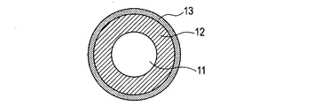
- 1A to 1C are schematic views of the charging member of the present invention.
- the charging member according to the present invention can include a metal core 11 as a conductive support and an elastic layer 12 provided on the outer periphery thereof.
- the elastic layer 12 is a conductive layer and is made of the ion conductive resin according to the present invention.
- a surface layer 13 may be formed on the surface of the elastic layer 12.
- at least one of the elastic layer 12 or the surface layer 13 is a conductive layer and is made of the ion conductive resin according to the present invention.
- FIG. 1C a three-layer structure in which the intermediate layer 14 is disposed between the elastic layer 12 and the surface layer 13 or a multilayer structure in which a plurality of intermediate layers 14 are disposed may be employed.
- at least one of the layers is a conductive layer, and the conductive layer is made of the ion conductive resin according to the present invention.
- conductive support it can be appropriately selected from those known in the field of electrophotographic conductive members.
- the conductive layer according to the present invention contains, as a binder resin, an ion conductive resin having either one or both ion exchange groups selected from quaternary ammonium ions and sulfonate ions in the molecular structure, and a specific resin. Contains carrier molecules.
- the ion exchange group according to the present invention is covalently bonded to the resin and is ion dissociated.
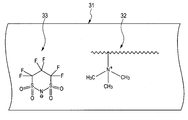
- FIG. 3 is a schematic cross-sectional view of one embodiment of the conductive layer according to the present invention.
- the conductive layer 31 includes an ion conductive resin 32 formed by covalently bonding a quaternary ammonium ion to a polymer chain as an ion exchange group. Is included as a binder resin.
- the conductive layer 31 includes carrier molecules 33 represented by the formula (1) as free carrier molecules.
- Carrier molecule is originally a counter ion of the above-described ion exchange group.
- the carrier molecules are dissociated from the above-described ion exchange groups and exist in a free state. Then, by applying a DC voltage to the conductive member, the free carrier molecules move through the binder resin to achieve ionic conduction.
- carrier molecules having a small ⁇ it is possible to reduce the occurrence of uneven electrical resistance on the charging member when a voltage is applied to the charging member for a long time.
- carrier molecules having a small ⁇ are relatively disadvantageous compared to carrier molecules having a large ⁇ in conducting the conductive layer.
- the present inventors have repeatedly investigated carrier molecules that can achieve both a high level of conductivity of the conductive layer and a reduction in the occurrence of uneven electrical resistance on the conductive member.
- the conductive layer contains at least one selected from carrier molecules represented by the following formulas (1) to (5). I found it.
- the binder resin contains sulfonate ions in the molecule, it has been found that the conductive layer preferably contains at least one selected from carrier molecules represented by the following formulas (6) to (10). .
- n 1 and n 2 each independently represents an integer of 1 to 4.
- R 1 represents a hydrocarbon group having 1 to 10 carbon atoms and may contain a hetero atom.
- Specific examples of the carrier molecule represented by the above formula (5) are given below. Methyl sulfonate, ethyl sulfonate, n-butyl sulfonate, sec-butyl sulfonate, tert-butyl sulfonate, n-hexyl sulfonate, n-octyl sulfonate, n-decyl sulfonate and the like.
- R 2 , R 3 and R 4 each independently represent hydrogen or a hydrocarbon group having 1 to 10 carbon atoms and may contain a hetero atom.
- R 5 , R 6 , R 7 and R 8 each independently represent hydrogen or a hydrocarbon group having 1 to 10 carbon atoms and may contain a hetero atom.
- R 9 and R 10 each independently represent hydrogen or a hydrocarbon group having 1 to 10 carbon atoms, and may contain a hetero atom.
- R 11 , R 12 , R 13 and R 14 each independently represent a hydrocarbon group having 1 to 10 carbon atoms and may contain a hetero atom.
- R 15 , R 16 , R 17 and R 18 each independently represent a hydrocarbon group having 1 to 10 carbon atoms and may contain a hetero atom.
- the carrier molecule having the structure represented by the formulas (1) to (10) is characterized by an extremely large molecular size compared to general carrier molecules such as protons and halogen ions. Therefore, it is considered that the ion mobility ⁇ is small and the object of the present invention can be achieved.
- the charging member when R 11 to R 14 are hydrocarbon groups having 11 or more carbon atoms, the charging member is applied when a DC voltage is applied for a long time. It was recognized that the electrical resistance of the glass tends to increase. This is considered to be caused by the entanglement between the binder resin and R 11 to R 14 . It is presumed that the electrical resistance has increased as a result of restricting the movement of carrier molecules due to the entanglement with the binder resin.
- carrier molecules having a large molecular size and a structure that hardly causes entanglement with the binder resin are preferred in the present invention, and among the carrier molecules, in particular, the formulas (1) to (4) And carrier molecules of formulas (6) to (8) are preferred.
- the carrier molecule represented by the formula (1) and the carrier molecule represented by the formula (2) are particularly suitable. That is, the carrier molecules represented by the formulas (1) and (2) are less likely to be entangled with the binder resin in the conductive layer, and the carrier molecules are highly hydrophobic, so that the charging member can be used even in a low humidity environment. This is because the electrical resistance can be sufficiently reduced.
- the carrier molecule represented by the formula (1) has a cyclic structure, entanglement with the binder resin is less likely to occur in the conductive layer. Therefore, although the ⁇ is low, the conductive layer can be made more conductive.
- the carrier molecule according to the present invention has a high affinity with the binder resin, it is preferable in that the carrier molecule can be uniformly dispersed with the binder resin and electric resistance unevenness due to dispersion unevenness can be further reduced.
- the carrier molecule according to the present invention exhibits the properties of an ionic liquid, it exists as a liquid even in a state where the amount of water is small, and can move in the binder resin. Furthermore, it is suitable also in the point which can improve the fall of the electrical resistance in a low humidity environment.
- the ionic liquid refers to a molten salt having a melting point of 100 degrees or less.
- the conductive layer according to the present invention may contain carrier molecules that contribute to ionic conduction other than the carrier molecules represented by the above formulas (1) to (10).
- the ratio of the carrier molecules represented by the above formulas (1) to (10) to the carrier molecules contributing to ion transmission contained in the conductive layer according to the present invention is 50 mol% or more and 100 mol%. In particular, it is particularly preferably 70 mol% or more and 100 mol% or less.
- the ion conductive resin is stirred in a dilute aqueous solution of hydrochloric acid or sodium hydroxide, and carrier molecules in the ion conductive resin are extracted into the aqueous solution.
- the aqueous solution after extraction is dried, the extract is collected, and mass spectrometry is performed with a time-of-flight mass spectrometer (TOF-MS), whereby carrier molecules can be identified and quantified.
- TOF-MS time-of-flight mass spectrometer
- the carrier molecule in the extract is a cation or anion molecule, even when the molecular weight of the carrier molecule is high, it can be analyzed without decomposing the carrier molecule in TOF-MS measurement.
- elemental analysis is performed by inductively coupled plasma (ICP) emission analysis of the extract, and combined with the results of mass spectrometry, it becomes easier to identify and quantify carrier molecules.
- ICP inductively coupled plasma
- Binder resin As the binder resin according to the present invention, an ion conductive resin having any one or both selected from a quaternary ammonium group and a sulfonic acid group in the molecular structure is used. And as an ion conductive resin which concerns on this invention, it is preferable to use what does not have the carrier molecule which contributes to ion conduction other than the carrier molecule based on this invention as a counter ion of a quaternary ammonium group. This is to prevent generation of large electric resistance unevenness in the conductive layer due to the presence of carrier molecules having different carrier mobility in the conductive layer.
- an ion conductive rubber typified by epichlorohydrin rubber has a low electrical resistance when vulcanized.
- the vulcanization accelerator used at the time of vulcanization forms a salt with chlorine released by heating, sulfur of additive, sulfur released from vulcanization accelerator, etc., and expresses the function as an ionic conductive agent It is thought to do.
- chlorine ions, sulfur ions, ions derived from vulcanization accelerators, and the like are generated as carrier molecules.
- the ion conductive resin according to the present invention is preferably a resin from which it is difficult to produce a compound exhibiting ionic conductivity by polymerization or heating.
- the resin that satisfies the above conditions include an epoxy resin having an ion exchange group, a urethane resin, an ester resin, an amide resin, an imide resin, an amideimide resin, a phenol resin, a vinyl resin, a silicone resin, and a fluorine resin.
- the resin group described above can produce a resin only with a monomer component or polymer component as a raw material and an ionic conductive agent that reacts with the resin and binds to the resin via a covalent bond, the types of carrier molecules that contribute to ionic conduction Can be reduced as much as possible.
- the ionic conductive resin preferably has an ethylene oxide unit in the molecular structure.
- Content of an ethylene oxide unit can be set suitably.
- the ethylene oxide unit content correlates with the moisture content in the ion conductive resin, it tends to dominate the temperature / humidity dependence of the electrical resistance value of the ion conductive resin.
- the content of the ethylene oxide unit can be adjusted to a range of 30 wt% to 80 wt%. More specifically, it is preferably 40 wt% or more and 60 wt% or less. When the content is 40 wt% or more, it is possible to prevent an increase in electrical resistance in a low temperature / low humidity environment.
- content of an ethylene oxide unit is computable as a weight ratio of the ethylene oxide unit in the binder resin as a raw material.
- the ion conductive resin according to the present invention can be produced by, for example, the following method using (1) an ion conductive agent as a raw material and (2) a polymer or monomer as a raw material for a binder resin.
- an ionic conductive agent as a raw material;
- an ion conductive agent having a portion capable of chemically reacting with the binder resin and having either a quaternary ammonium group or a sulfonic acid group is prepared.
- the moiety capable of chemically reacting with the binder resin include a binding site of a halogen atom (fluorine, chlorine, bromine and iodine atom) and a reactive functional group.
- reactive functional groups include carboxyl groups, acid groups such as acid anhydrides, hydroxyl groups, amino groups, mercapto groups, alkoxy groups, vinyl groups, glycidyl groups, epoxy groups, nitrile groups, carbamoyl groups, and the like.
- the carrier molecule according to the present invention is introduced into the ionic conductive agent prepared in (1-1) above. Specifically, by carrying out an ion exchange reaction between the salt of the carrier molecule according to the present invention and the quaternary ammonium group or sulfonic acid group of the ionic conductive agent prepared in the above (1-1), An ionic conductive agent into which carrier molecules according to the invention are introduced can be obtained.
- the ionic conductive agent prepared in (1-1) is glycidyltrimethylammonium chloride will be described as an example.
- lithium bis (trifluoromethanesulfonyl) imide is prepared as the carrier molecule salt.
- each of the ion conductive agent and the salt of the carrier molecule is dissolved in purified water.
- each aqueous solution is mixed and stirred to cause an ion exchange reaction, whereby chlorine ions having high ion exchange properties are replaced with bis (trifluoromethanesulfonyl) imide ions.
- chlorine ions having high ion exchange properties are replaced with bis (trifluoromethanesulfonyl) imide ions.
- the produced glycidyltrimethylammonium bis (trifluoromethanesulfonyl) imide is a hydrophobic ionic liquid, water-soluble lithium chloride as a by-product can be easily removed.
- ionic conductive agents composed of carrier molecules according to the present invention have ionic liquid characteristics, even when the reactive ionic conductive agent obtained by the above-described method is hydrophilic, chloroform, dichloromethane, dichloroethane, By-products can be easily removed by selecting a solvent such as methyl isobutyl ketone.
- the polymer or monomer as the raw material of the binder resin can be used without any particular limitation as long as it reacts with the reactive functional group contained in the ionic conductive agent.
- a specific example is given. Polyglycidyl compound, polyamine compound, polycarboxy compound, polyisocyanate compound, polyhydric alcohol compound, polyisocyanate compound, phenol compound, vinyl compound, etc., compound having two or more reactive functional groups, compound having polymerizable property alone etc.
- an ionic conductive agent obtained by ion exchange of chloride ions of glycidyltrimethylammonium chloride with cyclohexafluoropropane-1,3-bis (sulfonyl) imide is used.
- a method for synthesizing the ion conductive resin according to the present invention will be described.
- Polypropylene glycol diglycidyl ether and polypropylene glycol bis (2-aminopropyl ether) are prepared as raw materials for the binder resin.
- a coating material is prepared by dissolving the ionic conductive agent and the raw material polymer in a solvent such as isopropyl alcohol.
- an ionic conductive resin in which a glycidyl group and an amino group react and a quaternary ammonium having a carrier molecule as a counter ion according to the present invention is bonded. can get.
- the addition amount of the ionic conductive agent according to the present invention can be appropriately set, and the ionic conductive agent is contained in a proportion of 0.5% by mass or more and 20% by mass or less with respect to the polymer or monomer as the raw material of the binder resin. It is preferable to mix.
- the method for synthesizing the ion conductive resin according to the present invention is not limited to the method described above.
- the ions according to the present invention are ion-exchanged with the carrier molecules according to the present invention.
- a method of synthesizing a conductive resin can also be employed.
- a filler, a softening agent, a processing aid, a tackifier, an anti-tacking agent, a dispersant which are generally used as a resin compounding agent, as long as the effects of the present invention are not impaired.
- a foaming agent or the like can be added.
- the conductive member according to the present invention can be suitably used, for example, as a charging member for contacting a member to be charged such as a photoconductor to charge the member to be charged.
- a charging member for contacting a member to be charged such as a photoconductor to charge the member to be charged.
- the process cartridge is configured to be detachable from the image forming apparatus main body.
- the conductive member according to the present invention can be suitably used.
- the ion conductive resin of the present invention can be used as a developing member, a transfer member, a charge eliminating member, or a conveying member such as a paper feed roller.
- FIG. 1A to 1C are schematic views showing the form of a charging roller which is a kind of electrophotographic conductive member of the present invention.
- the charging roller may have a single-layer configuration including a cored bar 11 and an elastic layer 12 provided on the outer periphery thereof.
- FIG. 1A A two-layer structure in which the surface layer 13 is disposed may be used.
- FIG. 1C a multilayer structure in which several intermediate layers 14 and adhesive layers are arranged between the elastic layer 12 and the surface layer 13 may be employed.
- at least one of the elastic layer 12, the surface layer 13, and the intermediate layer 14 is a conductive layer, and the ion conductive resin according to the present invention may be used for any layer.
- the ion conductive resin of the present invention since it is near the surface of the charging roller that is involved in the discharge as the charging roller, it is preferable to use the ion conductive resin of the present invention in the vicinity of the surface layer that can improve discharge unevenness. In this case, it is not always necessary to use the ion conductive resin of the present invention for the outermost layer, and as long as it does not affect discharge unevenness, the outermost layer is subjected to a non-adhesive treatment for the purpose of preventing adhesion of toner and external additives. It doesn't matter.
- non-adhesive treatment of the outermost layer a method of curing the surface by irradiating the surface of the charging roller with energy rays such as electron beam, ultraviolet ray, X-ray and microwave, and making the surface non-adhesive, acrylic resin, polyurethane, polyamide, Non-adhesive resins such as polyester, polyolefin, and silicone resin may be formed as the outermost surface layer.
- energy rays such as electron beam, ultraviolet ray, X-ray and microwave
- the electric resistance of the conductive member according to the present invention is 1 ⁇ 10 3 ⁇ ⁇ cm or more and 1 ⁇ 10 9 ⁇ ⁇ cm or less, but the electric resistance is 1 ⁇ 10 5 ⁇ ⁇ cm or more and 1 ⁇ 10 8. Effective when ⁇ ⁇ cm or less.
- the occurrence of abnormal discharge due to leakage can be suppressed by setting it to 1 ⁇ 10 5 ⁇ ⁇ cm or more, and the occurrence of image defects due to insufficient electrical resistance can be suppressed by setting it to 1 ⁇ 10 8 ⁇ ⁇ cm or less.
- the rubber component forming the elastic layer 12 is not particularly limited, and is for electrophotography.
- Known rubbers can be used in the field of conductive members. Specifically, epichlorohydrin homopolymer, epichlorohydrin-ethylene oxide copolymer, epichlorohydrin-ethylene oxide-allyl glycidyl ether terpolymer, acrylonitrile-butadiene copolymer, acrylonitrile-butadiene copolymer hydrogenated product, acrylic Examples thereof include rubber and urethane rubber.
- the surface layer 13 can use a resin known in the field of electrophotographic conductive members. . Specific examples include acrylic resin, polyurethane, polyamide, polyester, polyolefin, and silicone resin.
- the resin forming the surface layer the surface of the particles may be coated with conductive oxides such as carbon black, graphite, and tin oxide, metals such as copper and silver, oxides and metals, if necessary.
- an ion conductive agent having ion exchange performance such as conductive particles and quaternary ammonium salts imparted with conductivity may be used.
- the electrophotographic apparatus according to the present invention only needs to have the electrophotographic conductive member according to the present invention, and an example of the schematic configuration is shown in FIG.
- An electrophotographic photosensitive member 44 (hereinafter also referred to as “photosensitive member”), a process cartridge in which a charging device having a charging member 45 made of a conductive member according to the present invention is integrated, a latent image forming device (not shown), and a latent image And a transfer device for transferring the toner image to a transfer material 47 such as paper. Further, it includes a cleaning device 48 that collects toner remaining on the photoconductor after the toner image is transferred, a fixing device 49 that fixes the toner image on the transfer material, and the like.
- the photosensitive member 44 is a rotary drum type having a photosensitive layer on a conductive substrate, and is rotated at a predetermined peripheral speed (process speed) in the direction of the arrow.
- the charging roller 45 is set to a predetermined voltage by a power source applied from the AC power source 50, and is driven to rotate in accordance with the rotation of the photosensitive member brought into contact with the predetermined pressing force, thereby charging the photosensitive member to a predetermined potential.
- the latent image forming apparatus includes an exposure apparatus such as a laser beam scanner that outputs a laser beam 41 that forms a latent image on the photosensitive member 44.
- an electrostatic latent image is formed on the uniformly charged photoconductor 44.
- the electrostatic latent image formed on the photoconductor 44 is conveyed to a toner having the same polarity as that of the photoconductor 44 by a developing sleeve or a developing roller 46 disposed close to or in contact with the photoconductor 44, and is subjected to reversal development.
- the electrostatic latent image is developed to form a toner image.
- the toner image on the photoconductor 44 is transferred to a transfer material 47 such as plain paper conveyed by a paper feed system between the transfer roller 42 and the photoconductor in the transfer device.
- the toner image on the transfer material 47 is fixed on the transfer material by a heating roller or the like, and is discharged out of the apparatus to obtain an output image.
- the residual toner on the photoconductor 44 is mechanically scraped off by the blade-type cleaning member 43 in the cleaning device 48 and is collected in the collection container of the cleaning device 48.
- the charging roller 45 made of the conductive member according to the present invention and another electrophotographic member, for example, the photosensitive member 44 are integrated, and can be attached to and detached from the main body of the electrophotographic apparatus. It is configured.
- a sectional view of the process cartridge according to the present invention is shown in FIG.
- the process cartridge shown in FIG. 5 includes a photosensitive device 44, a charging device having a charging roller 45, a developing device having a developing roller 46, a toner supply roller 51 and a developing blade 52, a cleaning device 54 having a cleaning blade 53, and the like. It is integrated and detachable from the main body of the electrophotographic apparatus.
- A Coating liquid No. for conductive layer formation Preparation of 1-42; ⁇ Preparation Example A1: Coating liquid No. Preparation of 1> (1-1) Preparation of ionic conductive agent;
- ionic conductive agent having a reactive functional group 8.56 g (56.5 mmol) of glycidyltrimethylammonium chloride was dissolved in 50 ml of purified water and stirred for 1 hour to obtain an aqueous solution of the ionic conductive agent.
- symbols A-1 to A-7 representing ion conductive agent species
- symbols B-1 to B-15 representing carrier molecular species subjected to ion exchange
- raw material monomer / ion conductive resin / Tables 2 to 4 show the compound names indicated by the symbols C-1 to C-11 representing the raw polymer.
- a device having a core bar supply mechanism and a conductive roller discharge mechanism is prepared in the cross head extruder, and a core bar conveying speed is 60 mm / sec, and a die having an inner diameter of ⁇ 12.5 mm is attached to the cross head.
- the extruder and crosshead were adjusted to 80 ° C.
- a layer of an unvulcanized rubber composition was formed around the core bar of a stainless steel rod having an outer diameter of 6 mm and a length of 258 mm supplied to the crosshead.
- a core metal whose peripheral surface is coated with a layer of an unvulcanized rubber composition is placed in a hot air vulcanization furnace at 170 ° C. and heated for 60 minutes to crosslink the layer of the unvulcanized rubber composition.
- a rubber elastic layer was obtained. Thereafter, the end portion was cut and removed so that the length of the rubber was 228 mm. Finally, the surface of the rubber elastic layer was polished with a recovery grindstone and formed into a crown shape having a center diameter of 12 mm and an average diameter of 11.8 mm from the center to the left and right ends of 90 mm. 1 was obtained.
- the cylindrical mold was heated at a temperature of 120 ° C. for 8 minutes, then cooled to a temperature of 25 ° C., and the stainless steel rod having a silicone rubber layer formed on the peripheral surface was removed. Thereafter, the silicone rubber layer was treated at a temperature of 200 ° C. for 60 minutes to cure the silicone rubber layer, and an elastic roller No. 1 having an elastic body layer having a thickness of 3.0 mm formed on the peripheral surface of the stainless steel rod. 3 was obtained.
- Elastic roller No. 1 was applied to the previously prepared coating solution No. 1 dipping once, the coating liquid No. 1 coating film was formed.
- the dipping coating dipping time is 9 seconds, and the dipping coating lifting speed is adjusted so that the initial speed is 20 mm / sec and the final speed is 2 mm / sec. Between 20 mm / sec and 2 mm / sec, The speed was changed linearly.
- the elastic roller 1 having a coating film formed on the surface was placed in an environment at a temperature of 25 ° C. for 30 minutes.
- the elastic roller 1 is placed in a hot air circulating dryer set at a temperature of 90 ° C. for 1 hour, and further placed in a hot air circulating dryer set at a temperature of 160 ° C. for 1 hour to react the coating film on the elastic layer. A surface layer as a conductive layer was formed.
- the charging roller No. 1 was obtained.
- the obtained charging roller 1 was subjected to the following evaluation.
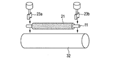
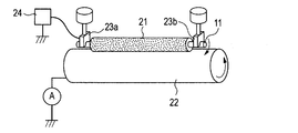
- FIGS. 2A and 2B are explanatory diagrams of a method for measuring the current value of the charging roller. As shown in FIGS. 2A and 2B, the charging roller is placed on a metal cylinder 22 having the same curvature as that of the photosensitive member in the electrophotographic apparatus under the same load as in the case of use in an electrophotographic image forming apparatus. On the other hand, a current value is measured when a current is passed in a state where the electrophotographic apparatus is brought into contact with the same load as in the usage state. In FIG.
- 2A, 23a and 23b are bearings fixed to weights, and 21 is a charging roller as a subject. Then, stress that pushes vertically downward is applied to both ends of the conductive support 11 of the charging roller 21.
- a metal cylinder 22 is arranged vertically below the charging roller so that the charging roller 21 and the rotation axis are parallel to each other. Then, the charging roller is pressed against the bearings 23a and 23b as shown in FIG. 2B while rotating the metal cylinder 22 by a driving device (not shown).
- the metal cylinder 22 is rotated at the same speed as the rotation speed of the photoconductor in the usage state of the electrophotographic apparatus, and a DC voltage of ⁇ 200 V is applied by the power supply 24 while the charging roller 21 is rotated by the rotation of the metal cylinder 22.
- a DC voltage of ⁇ 200 V is applied by the power supply 24 while the charging roller 21 is rotated by the rotation of the metal cylinder 22.
- the time average of the current flowing out from the cylindrical metal 22 was measured with an ammeter A, and the time average of the results of measurement for 5 seconds was calculated.
- the charging roller No. as the subject is measured.
- Two 1s were prepared.
- the charging roller No. Applying a force of 5N to both ends of the shaft 1 to bring it into contact with a cylindrical metal having a diameter of 30 mm, rotating the cylindrical metal at a peripheral speed of 150 mm / s, measuring the current value, and obtaining the electric resistance value It was.
- the other charging roller No. 1 for a temperature of 15 ° C./humidity of 10% R.P. H. (L / L environment) was allowed to acclimate to the L / L environment for 48 hours. Thereafter, in the same environment, the charging roller No.
- ⁇ Evaluation 2 Bleed evaluation> Charging roller No. 1 is placed on a polyethylene terephthalate (PET) sheet, and the charging roller No. 1 is set. A load of 500 g is applied to both ends of the shaft of No. 1 to charge the charging roller no. The surface of 1 was brought into contact with a PET sheet. This state was measured at a temperature of 40 ° C./humidity of 95% R.D. H. For one week. After that, the charging roller No. 1 is removed from the PET sheet, and the charging roller No. 1 of the PET sheet is removed. The surface on which 1 was in contact was observed with an optical microscope (10 times). Charging roller No. Whether or not the bleed from the elastic layer 1 adhered to the surface of the PET sheet through the surface layer was evaluated based on the criteria described in Table 8 below.
- the electrophotographic images were output by causing the laser printer to perform intermittent image forming operations.
- the intermittent image forming operation after outputting two images, the rotation of the electrophotographic photosensitive drum is stopped for about 3 seconds, and the image forming operation is performed again.
- the first to 40000th sheets were character images with a printing density of 1%, and the last sheet was a halftone image.
- the halftone image is an image in which a horizontal line having a width of 1 dot and an interval of 2 dots is drawn in the direction perpendicular to the rotation direction of the electrophotographic photosensitive member. Then, the 40th halftone image was visually observed and evaluated according to the criteria shown in Table 9 below.
- ⁇ Evaluation 4 Evaluation by Spotted Image Defect>
- a charging roller for an electrophotographic laser printer (trade name: Laserjet 4515n, manufactured by HP), a charging roller No. 1 is used. 1 was installed. The output speed of the recording medium of this laser printer is 370 mm / sec, and the image resolution is 1200 dpi.
- the laser printer By causing the laser printer to perform an intermittent image forming operation, 40,000 electrophotographic images were output. In the intermittent image forming operation, after outputting two images, the rotation of the electrophotographic photosensitive drum is stopped for about 3 seconds, and the image forming operation is performed again. The image output at this time was an H-Line image.
- ⁇ Evaluation 5 Molar ratio of carrier molecules according to the present invention to all carrier molecules in the conductive layer>
- the surface layer of the charging roller 1 was scraped and dissolved in a dilute aqueous solution of hydrochloric acid to extract carrier molecules in the ion conductive resin.
- the aqueous solution after extraction is dried, and the extract is collected, then subjected to mass spectrometry using a time-of-flight mass spectrometer (TOF-MS) and ICP emission analysis, and the amount of total carrier molecules present in the surface layer, and
- the amount of the carrier molecule according to the present invention was detected, and the molar ratio of the carrier molecule according to the present invention to the total carrier molecules in the conductive layer was determined.
- TOF-MS time-of-flight mass spectrometer
- Examples 2 to 42> In the formation of the conductive layer as the surface layer, No. 1 shown in Table 10 was used.
- the charging roller No. 1 was the same as the charging roller 1 except that the coating solution was used. 2 to 42 were prepared. These charging rollers were evaluated in the same manner as the charging roller 1.
- Elastic roller No. 1 is an elastic roller no. 2 and the formation of the surface layer was changed to No. 1 described in Table 11.
- the charging roller No. was used except that the coating liquid was used.
- the charging roller no. 43 to 53 were prepared and used for Evaluation 1 to Evaluation 5. The results are also shown in Table 11.
- Example 54 A stainless steel rod having a diameter of 6 mm and a length of 258 mm was placed in a cylindrical mold. In the cavity of this cylindrical mold, the coating liquid No. The resin mixture excluding IPA from 3 was injected and filled. Next, the cylindrical mold was heated at a temperature of 90 ° C. for 1 hour, and further heated at a temperature of 160 ° C. for 1 hour. Thereafter, the cylindrical mold was cooled to a temperature of 25 ° C., and the stainless steel rod having a conductive layer having a thickness of 3.0 mm formed on the peripheral surface was removed. This is the charging roller No. 54. This charging roller No. 54 was subjected to Evaluations 1 to 5. The results are shown in Table 12.
- the obtained coating material for forming the protective layer was dipped once on the outer periphery of the charging roller of Example 10 and air-dried at room temperature for 30 minutes or more. Subsequently, it dried for 1 hour with the hot air circulating dryer set to 90 degreeC, and also dried for 1 hour with the hot air circulating dryer set to 160 degreeC, and formed the outermost layer on the charging roller.
- the dipping coating dipping time is 9 seconds, and the dipping coating lifting speed is adjusted so that the initial speed is 20 mm / sec and the final speed is 2 mm / sec. Between 20 mm / sec and 2 mm / sec, the speed is linear. The speed was changed.
- the charging roller No. 1 having the protective layer. 55 was created. This charging roller No. 55 was subjected to Evaluation 1 to Evaluation 5. The results are shown in Table 12.
- Example 56 Elastic roller No. 3 and coating liquid No. 3 for forming the surface layer. 4 except that the developing roller No. 4 was used in the same manner as in Example 1. 1 was created. Development roller No. 1 was subjected to Evaluation 1, Evaluation 2, Evaluation 5, and Evaluation 6 below.
- Electrophotographic image formation test> As an electrophotographic apparatus, a laser printer (trade name: LBP5400, manufactured by Canon Inc.) was prepared. Then, the contact pressure between the developing roller and the photosensitive member and the penetration amount were adjusted so that the toner coating amount on the developing roller was 0.35 mg / cm 2 . Also, a toner supply roller made of a soft urethane sponge is provided to scrape old toner from the developing roller and supply new toner to the developing roller. As a developing roller of this laser printer, a developing roller No. No.
- a developing roller No. was prepared in the same manner as in Example 56 except that the above coating solution was used. 2 to 4 were prepared and used for evaluations 1 to 2, evaluations 5 and 6. The results are also shown in Table 15.
- Coating liquid No. 4 is the coating liquid No.
- a developing roller C-4 was prepared in the same manner as in Example 56 except that the surface layer was changed to 44, and used for evaluations 1-2, 5, and 6. The results are shown in Table 16.
- the ionic conductive agent which concerns on this comparative example does not have a reactive functional group. Therefore, the binder resin according to this comparative example does not have a quaternary ammonium group and a sulfonic acid group in the molecular structure, and does not correspond to the ion conductive resin according to the present invention.
Landscapes
- Physics & Mathematics (AREA)
- General Physics & Mathematics (AREA)
- Engineering & Computer Science (AREA)
- General Engineering & Computer Science (AREA)
- Plasma & Fusion (AREA)
- Mechanical Engineering (AREA)
- Electrostatic Charge, Transfer And Separation In Electrography (AREA)
- Electrophotography Configuration And Component (AREA)
Priority Applications (7)
| Application Number | Priority Date | Filing Date | Title |
|---|---|---|---|
| BR112013022773-7A BR112013022773A2 (pt) | 2011-03-22 | 2012-03-16 | membro eletricamente condutor eletrofotográfico |
| KR1020137026996A KR101570592B1 (ko) | 2011-03-22 | 2012-03-16 | 전자 사진용 도전성 부재 |
| CN201280014378.6A CN103460145B (zh) | 2011-03-22 | 2012-03-16 | 电子照相用导电性构件 |
| EP12761245.5A EP2690501B1 (en) | 2011-03-22 | 2012-03-16 | Conductive member for electrophotography |
| KR1020157012281A KR101633242B1 (ko) | 2011-03-22 | 2012-03-16 | 전자 사진용 도전성 부재 |
| US13/532,770 US8668987B2 (en) | 2011-03-22 | 2012-06-25 | Electrophotographic electrically conductive member |
| US14/189,944 US9128403B2 (en) | 2011-03-22 | 2014-02-25 | Electrophotographic electrically conductive member |
Applications Claiming Priority (4)
| Application Number | Priority Date | Filing Date | Title |
|---|---|---|---|
| JP2011-062717 | 2011-03-22 | ||
| JP2011062717 | 2011-03-22 | ||
| JP2012-051718 | 2012-03-08 | ||
| JP2012051718A JP5875416B2 (ja) | 2011-03-22 | 2012-03-08 | 電子写真用導電性部材 |
Related Child Applications (1)
| Application Number | Title | Priority Date | Filing Date |
|---|---|---|---|
| US13/532,770 Continuation US8668987B2 (en) | 2011-03-22 | 2012-06-25 | Electrophotographic electrically conductive member |
Publications (1)
| Publication Number | Publication Date |
|---|---|
| WO2012127835A1 true WO2012127835A1 (ja) | 2012-09-27 |
Family
ID=46879015
Family Applications (1)
| Application Number | Title | Priority Date | Filing Date |
|---|---|---|---|
| PCT/JP2012/001851 Ceased WO2012127835A1 (ja) | 2011-03-22 | 2012-03-16 | 電子写真用導電性部材 |
Country Status (7)
| Country | Link |
|---|---|
| US (2) | US8668987B2 (enExample) |
| EP (1) | EP2690501B1 (enExample) |
| JP (1) | JP5875416B2 (enExample) |
| KR (2) | KR101633242B1 (enExample) |
| CN (3) | CN107219740B (enExample) |
| BR (1) | BR112013022773A2 (enExample) |
| WO (1) | WO2012127835A1 (enExample) |
Cited By (1)
| Publication number | Priority date | Publication date | Assignee | Title |
|---|---|---|---|---|
| CN105319875A (zh) * | 2014-07-09 | 2016-02-10 | 佳能株式会社 | 电子照相感光构件及其制造方法、处理盒和电子照相设备 |
Families Citing this family (51)
| Publication number | Priority date | Publication date | Assignee | Title |
|---|---|---|---|---|
| JP6000580B2 (ja) | 2011-03-29 | 2016-09-28 | キヤノン株式会社 | 接触帯電ローラ、現像部材、導電性部材およびこれらの製造方法、プロセスカートリッジならびに電子写真装置 |
| JP5893432B2 (ja) | 2011-03-30 | 2016-03-23 | キヤノン株式会社 | イオン導電性樹脂、および電子写真用導電性部材 |
| JP5972150B2 (ja) | 2011-12-19 | 2016-08-17 | キヤノン株式会社 | 電子写真用導電性部材、プロセスカートリッジおよび電子写真画像形成装置 |
| CN104011602B (zh) | 2011-12-22 | 2016-08-17 | 佳能株式会社 | 导电性构件、处理盒和电子照相设备 |
| JP5693441B2 (ja) | 2011-12-26 | 2015-04-01 | キヤノン株式会社 | 電子写真用導電性部材、プロセスカートリッジおよび電子写真装置 |
| JP6003528B2 (ja) * | 2012-10-24 | 2016-10-05 | 富士ゼロックス株式会社 | 半導電性ロール及びその製造方法並びに画像形成装置 |
| CN105579913B (zh) | 2013-09-27 | 2018-02-16 | 佳能株式会社 | 电子照相用导电性构件、处理盒和电子照相设备 |
| JP6587418B2 (ja) * | 2014-05-15 | 2019-10-09 | キヤノン株式会社 | 電子写真用部材、プロセスカートリッジ及び電子写真装置 |
| CN106687869B (zh) | 2014-09-10 | 2019-04-16 | 佳能株式会社 | 电子照相用导电性构件和季铵盐 |
| US9568846B2 (en) | 2014-11-28 | 2017-02-14 | Canon Kabushiki Kaisha | Electrophotographic photosensitive member, method for producing the same, process cartridge, and electrophotographic apparatus |
| US9625838B2 (en) * | 2014-11-28 | 2017-04-18 | Canon Kabushiki Kaisha | Electrophotographic apparatus, process cartridge, and image forming method |
| US9529284B2 (en) | 2014-11-28 | 2016-12-27 | Canon Kabushiki Kaisha | Process cartridge, image forming method, and electrophotographic apparatus |
| JP6666031B2 (ja) | 2014-12-26 | 2020-03-13 | キヤノン株式会社 | 電子写真用部材、その製造方法、プロセスカートリッジおよび電子写真装置 |
| JP6706101B2 (ja) | 2015-03-27 | 2020-06-03 | キヤノン株式会社 | 電子写真用の導電性部材、プロセスカートリッジおよび電子写真装置 |
| US9740133B2 (en) | 2015-09-30 | 2017-08-22 | Canon Kabushiki Kaisha | Charging member, process cartridge and electrophotographic image forming apparatus |
| JP6590652B2 (ja) * | 2015-11-16 | 2019-10-16 | キヤノン株式会社 | 現像部材、その製造方法、プロセスカートリッジおよび電子写真画像形成装置 |
| US10678158B2 (en) | 2016-09-26 | 2020-06-09 | Canon Kabushiki Kaisha | Electro-conductive member for electrophotography, process cartridge, and electrophotographic image forming apparatus |
| JP6976774B2 (ja) | 2016-09-27 | 2021-12-08 | キヤノン株式会社 | 電子写真用導電性部材、プロセスカートリッジおよび電子写真画像形成装置 |
| US10416588B2 (en) | 2016-10-31 | 2019-09-17 | Canon Kabushiki Kaisha | Charging member, process cartridge, electrophotographic image forming apparatus, and method for manufacturing charging member |
| JP6850210B2 (ja) * | 2017-06-29 | 2021-03-31 | 住友理工株式会社 | 電子写真機器用帯電部材 |
| CN112020678B (zh) | 2018-04-18 | 2022-11-01 | 佳能株式会社 | 导电性构件、处理盒和电子照相图像形成设备 |
| WO2019203238A1 (ja) | 2018-04-18 | 2019-10-24 | キヤノン株式会社 | 導電性部材及びその製造方法、プロセスカートリッジ並びに電子写真画像形成装置 |
| CN111989622B (zh) | 2018-04-18 | 2022-11-11 | 佳能株式会社 | 显影构件、处理盒和电子照相设备 |
| WO2019203225A1 (ja) | 2018-04-18 | 2019-10-24 | キヤノン株式会社 | 導電性部材、プロセスカートリッジ及び電子写真画像形成装置 |
| CN112005173B (zh) | 2018-04-18 | 2023-03-24 | 佳能株式会社 | 导电性构件、处理盒和图像形成设备 |
| WO2019203227A1 (ja) | 2018-04-18 | 2019-10-24 | キヤノン株式会社 | 導電性部材、プロセスカートリッジ、および画像形成装置 |
| US10969709B2 (en) * | 2018-04-20 | 2021-04-06 | Canon Kabushiki Kaisha | Member for electrophotography, process cartridge and electrophotographic apparatus |
| US11022904B2 (en) | 2018-07-31 | 2021-06-01 | Canon Kabushiki Kaisha | Electrophotographic member, process cartridge and electrophotographic image forming apparatus |
| US10698347B2 (en) * | 2018-12-04 | 2020-06-30 | Canon Kabushiki Kaisha | Electrophotographic belt and image forming apparatus |
| JP7446878B2 (ja) | 2019-03-29 | 2024-03-11 | キヤノン株式会社 | 導電性部材、電子写真用プロセスカートリッジ、及び電子写真画像形成装置 |
| US11169454B2 (en) | 2019-03-29 | 2021-11-09 | Canon Kabushiki Kaisha | Electrophotographic electro-conductive member, process cartridge, and electrophotographic image forming apparatus |
| JP7401256B2 (ja) | 2019-10-18 | 2023-12-19 | キヤノン株式会社 | 電子写真装置、プロセスカートリッジ及びカートリッジセット |
| JP7330851B2 (ja) | 2019-10-18 | 2023-08-22 | キヤノン株式会社 | 電子写真装置、プロセスカートリッジ、及びカートリッジセット |
| CN114556230B (zh) | 2019-10-18 | 2024-03-08 | 佳能株式会社 | 电子照相用导电性构件、处理盒和电子照相图像形成装置 |
| JP7330852B2 (ja) | 2019-10-18 | 2023-08-22 | キヤノン株式会社 | 電子写真装置、プロセスカートリッジ、及びカートリッジセット |
| JP7336351B2 (ja) | 2019-10-18 | 2023-08-31 | キヤノン株式会社 | 電子写真装置、プロセスカートリッジ、及びカートリッジセット |
| US11112719B2 (en) | 2019-10-18 | 2021-09-07 | Canon Kabushiki Kaisha | Process cartridge and electrophotographic apparatus capable of suppressing lateral running while maintaining satisfactory potential function |
| JP7669134B2 (ja) | 2019-10-18 | 2025-04-28 | キヤノン株式会社 | 導電性部材、プロセスカートリッジ並びに電子写真画像形成装置 |
| JP7401255B2 (ja) | 2019-10-18 | 2023-12-19 | キヤノン株式会社 | 電子写真装置、プロセスカートリッジ、及びカートリッジセット |
| JP7337650B2 (ja) | 2019-10-18 | 2023-09-04 | キヤノン株式会社 | プロセスカートリッジおよび電子写真装置 |
| JP7321884B2 (ja) | 2019-10-18 | 2023-08-07 | キヤノン株式会社 | 電子写真装置、プロセスカートリッジ及びカートリッジセット |
| JP7337651B2 (ja) | 2019-10-18 | 2023-09-04 | キヤノン株式会社 | プロセスカートリッジ及び電子写真装置 |
| WO2021075441A1 (ja) | 2019-10-18 | 2021-04-22 | キヤノン株式会社 | 導電性部材、プロセスカートリッジ及び電子写真画像形成装置 |
| JP7404026B2 (ja) | 2019-10-18 | 2023-12-25 | キヤノン株式会社 | 電子写真装置、プロセスカートリッジ、及びカートリッジセット |
| JP7337649B2 (ja) | 2019-10-18 | 2023-09-04 | キヤノン株式会社 | プロセスカートリッジ及び電子写真装置 |
| CN114556231B (zh) | 2019-10-18 | 2023-06-27 | 佳能株式会社 | 导电性构件、其制造方法、处理盒以及电子照相图像形成设备 |
| JP7337652B2 (ja) | 2019-10-18 | 2023-09-04 | キヤノン株式会社 | プロセスカートリッジ及びそれを用いた電子写真装置 |
| US20210371661A1 (en) * | 2020-05-27 | 2021-12-02 | Canon Kabushiki Kaisha | Curable silicone rubber mixture, electrophotographic member, and electrophotographic image forming apparatus |
| WO2022097743A1 (ja) | 2020-11-09 | 2022-05-12 | キヤノン株式会社 | 導電性部材、プロセスカートリッジ、及び電子写真画像形成装置 |
| US12498646B2 (en) | 2023-09-27 | 2025-12-16 | Canon Kabushiki Kaisha | Electrophotographic conductive member, process cartridge, and electrophotographic image forming apparatus |
| JP2025056886A (ja) | 2023-09-27 | 2025-04-09 | キヤノン株式会社 | 電子写真部材、プロセスカートリッジ、及び電子写真画像形成装置 |
Citations (9)
| Publication number | Priority date | Publication date | Assignee | Title |
|---|---|---|---|---|
| JPH01142569A (ja) | 1987-11-27 | 1989-06-05 | Tokai Rubber Ind Ltd | 導電性ロール |
| JP2001074034A (ja) * | 1999-09-02 | 2001-03-23 | Tokai Rubber Ind Ltd | 導電性ロール |
| JP2001074033A (ja) * | 1999-09-02 | 2001-03-23 | Tokai Rubber Ind Ltd | 導電性ロール |
| JP2002132014A (ja) * | 2000-10-19 | 2002-05-09 | Ricoh Co Ltd | 帯電部材及び該帯電部材を有する画像形成装置 |
| JP2003202722A (ja) | 2001-10-16 | 2003-07-18 | Hokushin Ind Inc | 導電性ロール |
| JP2005350621A (ja) * | 2004-06-14 | 2005-12-22 | Kureha Corp | 半導電性ポリフッ化ビニリデン系樹脂組成物、半導電性樹脂成形物、及び該成形物の製造方法 |
| JP2007138113A (ja) * | 2005-11-22 | 2007-06-07 | Tokai Rubber Ind Ltd | 導電性ポリマー組成物およびそれを用いた電子写真機器用導電性部材 |
| JP2008224739A (ja) * | 2007-03-08 | 2008-09-25 | Ricoh Co Ltd | 導電性部材及びこの導電性部材を用いたプロセスカートリッジ及びこのプロセスカートリッジを用いた画像形成装置 |
| JP2010008878A (ja) * | 2008-06-30 | 2010-01-14 | Canon Inc | 現像剤担持体及び現像装置 |
Family Cites Families (16)
| Publication number | Priority date | Publication date | Assignee | Title |
|---|---|---|---|---|
| JP3000944B2 (ja) * | 1996-06-24 | 2000-01-17 | 富士ゼロックス株式会社 | 半導電性部材および半導電性クリーニング兼除電ブレード |
| US6391511B1 (en) * | 1998-04-17 | 2002-05-21 | Canon Kabushiki Kaisha | Developing apparatus, apparatus unit, and image forming method |
| CN100412131C (zh) * | 2001-01-17 | 2008-08-20 | 住友橡胶工业株式会社 | 导电性橡胶组合物、导电性聚合物的组合物、导电性硫化橡胶、导电性橡胶辊筒及导电性橡胶带 |
| JP2003302722A (ja) | 2002-04-09 | 2003-10-24 | Konica Minolta Holdings Inc | 熱現像感光材料とその処理方法 |
| JP3960214B2 (ja) * | 2002-11-29 | 2007-08-15 | 東海ゴム工業株式会社 | 電子写真機器部材用半導電性組成物およびそれを用いた電子写真機器部材 |
| JP2005120158A (ja) * | 2003-10-14 | 2005-05-12 | Japan Carlit Co Ltd:The | 導電性ポリウレタン樹脂及び該樹脂の製造方法並びに該樹脂を用いた電子写真装置用導電性部材 |
| CN1873547A (zh) * | 2005-05-31 | 2006-12-06 | 住友橡胶工业株式会社 | 电子照相用半导电橡胶构件 |
| JP5147510B2 (ja) | 2007-04-27 | 2013-02-20 | キヤノン株式会社 | 電子写真用ローラ部材の製造方法 |
| JP2010150356A (ja) * | 2008-12-25 | 2010-07-08 | Jsr Corp | イオン性官能基含有エポキシ樹脂 |
| CN102834784B (zh) | 2010-04-09 | 2014-12-10 | 佳能株式会社 | 显影剂承载构件、其制造方法和显影设备 |
| WO2012001881A1 (ja) | 2010-06-30 | 2012-01-05 | キヤノン株式会社 | 導電部材、プロセスカートリッジおよび電子写真画像形成装置 |
| KR101454128B1 (ko) | 2010-07-13 | 2014-10-22 | 캐논 가부시끼가이샤 | 전자 사진용 도전성 부재, 프로세스 카트리지 및 전자 사진 장치 |
| CN103003756B (zh) | 2010-07-20 | 2015-06-10 | 佳能株式会社 | 导电性构件、处理盒和电子照相设备 |
| JP6000580B2 (ja) | 2011-03-29 | 2016-09-28 | キヤノン株式会社 | 接触帯電ローラ、現像部材、導電性部材およびこれらの製造方法、プロセスカートリッジならびに電子写真装置 |
| JP5893432B2 (ja) | 2011-03-30 | 2016-03-23 | キヤノン株式会社 | イオン導電性樹脂、および電子写真用導電性部材 |
| EP2696245B1 (en) | 2011-04-01 | 2015-08-19 | Canon Kabushiki Kaisha | Conductive member, process cartridge, and electrophotographic device |
-
2012
- 2012-03-08 JP JP2012051718A patent/JP5875416B2/ja active Active
- 2012-03-16 CN CN201710265035.1A patent/CN107219740B/zh active Active
- 2012-03-16 CN CN201510222278.8A patent/CN104932221A/zh active Pending
- 2012-03-16 CN CN201280014378.6A patent/CN103460145B/zh active Active
- 2012-03-16 WO PCT/JP2012/001851 patent/WO2012127835A1/ja not_active Ceased
- 2012-03-16 BR BR112013022773-7A patent/BR112013022773A2/pt not_active Application Discontinuation
- 2012-03-16 KR KR1020157012281A patent/KR101633242B1/ko not_active Expired - Fee Related
- 2012-03-16 EP EP12761245.5A patent/EP2690501B1/en active Active
- 2012-03-16 KR KR1020137026996A patent/KR101570592B1/ko not_active Expired - Fee Related
- 2012-06-25 US US13/532,770 patent/US8668987B2/en not_active Expired - Fee Related
-
2014
- 2014-02-25 US US14/189,944 patent/US9128403B2/en active Active
Patent Citations (9)
| Publication number | Priority date | Publication date | Assignee | Title |
|---|---|---|---|---|
| JPH01142569A (ja) | 1987-11-27 | 1989-06-05 | Tokai Rubber Ind Ltd | 導電性ロール |
| JP2001074034A (ja) * | 1999-09-02 | 2001-03-23 | Tokai Rubber Ind Ltd | 導電性ロール |
| JP2001074033A (ja) * | 1999-09-02 | 2001-03-23 | Tokai Rubber Ind Ltd | 導電性ロール |
| JP2002132014A (ja) * | 2000-10-19 | 2002-05-09 | Ricoh Co Ltd | 帯電部材及び該帯電部材を有する画像形成装置 |
| JP2003202722A (ja) | 2001-10-16 | 2003-07-18 | Hokushin Ind Inc | 導電性ロール |
| JP2005350621A (ja) * | 2004-06-14 | 2005-12-22 | Kureha Corp | 半導電性ポリフッ化ビニリデン系樹脂組成物、半導電性樹脂成形物、及び該成形物の製造方法 |
| JP2007138113A (ja) * | 2005-11-22 | 2007-06-07 | Tokai Rubber Ind Ltd | 導電性ポリマー組成物およびそれを用いた電子写真機器用導電性部材 |
| JP2008224739A (ja) * | 2007-03-08 | 2008-09-25 | Ricoh Co Ltd | 導電性部材及びこの導電性部材を用いたプロセスカートリッジ及びこのプロセスカートリッジを用いた画像形成装置 |
| JP2010008878A (ja) * | 2008-06-30 | 2010-01-14 | Canon Inc | 現像剤担持体及び現像装置 |
Cited By (1)
| Publication number | Priority date | Publication date | Assignee | Title |
|---|---|---|---|---|
| CN105319875A (zh) * | 2014-07-09 | 2016-02-10 | 佳能株式会社 | 电子照相感光构件及其制造方法、处理盒和电子照相设备 |
Also Published As
| Publication number | Publication date |
|---|---|
| CN103460145A (zh) | 2013-12-18 |
| BR112013022773A2 (pt) | 2020-09-29 |
| KR101633242B1 (ko) | 2016-06-23 |
| JP2012212127A (ja) | 2012-11-01 |
| CN107219740A (zh) | 2017-09-29 |
| JP5875416B2 (ja) | 2016-03-02 |
| CN104932221A (zh) | 2015-09-23 |
| KR20150060994A (ko) | 2015-06-03 |
| US8668987B2 (en) | 2014-03-11 |
| CN103460145B (zh) | 2015-09-16 |
| EP2690501A1 (en) | 2014-01-29 |
| KR101570592B1 (ko) | 2015-11-19 |
| US20120263499A1 (en) | 2012-10-18 |
| EP2690501A4 (en) | 2014-10-22 |
| CN107219740B (zh) | 2019-10-15 |
| KR20130135957A (ko) | 2013-12-11 |
| US9128403B2 (en) | 2015-09-08 |
| US20140178096A1 (en) | 2014-06-26 |
| EP2690501B1 (en) | 2018-01-10 |
Similar Documents
| Publication | Publication Date | Title |
|---|---|---|
| JP5875416B2 (ja) | 電子写真用導電性部材 | |
| JP6071528B2 (ja) | 導電性部材、プロセスカートリッジ及び電子写真装置 | |
| JP5972150B2 (ja) | 電子写真用導電性部材、プロセスカートリッジおよび電子写真画像形成装置 | |
| US8852743B2 (en) | Electro-conductive member for electrophotography, process cartridge, and electrophotographic apparatus | |
| JP5312568B2 (ja) | 導電性部材、プロセスカートリッジおよび電子写真装置 | |
| JP6410664B2 (ja) | 電子写真用部材、プロセスカートリッジおよび電子写真装置 | |
| JP5882724B2 (ja) | 導電部材、プロセスカートリッジ及び電子写真装置 | |
| KR20140003606A (ko) | 이온 도전성 수지 및 전자 사진용 도전성 부재 | |
| JP5952945B2 (ja) | 電子写真用導電性部材 |
Legal Events
| Date | Code | Title | Description |
|---|---|---|---|
| 121 | Ep: the epo has been informed by wipo that ep was designated in this application |
Ref document number: 12761245 Country of ref document: EP Kind code of ref document: A1 |
|
| NENP | Non-entry into the national phase |
Ref country code: DE |
|
| ENP | Entry into the national phase |
Ref document number: 20137026996 Country of ref document: KR Kind code of ref document: A |
|
| REG | Reference to national code |
Ref country code: BR Ref legal event code: B01A Ref document number: 112013022773 Country of ref document: BR |
|
| ENP | Entry into the national phase |
Ref document number: 112013022773 Country of ref document: BR Kind code of ref document: A2 Effective date: 20130905 |