WO2012127755A1 - スクロール圧縮装置 - Google Patents
スクロール圧縮装置 Download PDFInfo
- Publication number
- WO2012127755A1 WO2012127755A1 PCT/JP2011/079469 JP2011079469W WO2012127755A1 WO 2012127755 A1 WO2012127755 A1 WO 2012127755A1 JP 2011079469 W JP2011079469 W JP 2011079469W WO 2012127755 A1 WO2012127755 A1 WO 2012127755A1
- Authority
- WO
- WIPO (PCT)
- Prior art keywords
- wall
- insulator
- scroll
- casing
- cup
- Prior art date
- Legal status (The legal status is an assumption and is not a legal conclusion. Google has not performed a legal analysis and makes no representation as to the accuracy of the status listed.)
- Ceased
Links
Images

Classifications
-
- F—MECHANICAL ENGINEERING; LIGHTING; HEATING; WEAPONS; BLASTING
- F04—POSITIVE - DISPLACEMENT MACHINES FOR LIQUIDS; PUMPS FOR LIQUIDS OR ELASTIC FLUIDS
- F04C—ROTARY-PISTON, OR OSCILLATING-PISTON, POSITIVE-DISPLACEMENT MACHINES FOR LIQUIDS; ROTARY-PISTON, OR OSCILLATING-PISTON, POSITIVE-DISPLACEMENT PUMPS
- F04C23/00—Combinations of two or more pumps, each being of rotary-piston or oscillating-piston type, specially adapted for elastic fluids; Pumping installations specially adapted for elastic fluids; Multi-stage pumps specially adapted for elastic fluids
- F04C23/02—Pumps characterised by combination with, or adaptation to, specific driving engines or motors
-
- F—MECHANICAL ENGINEERING; LIGHTING; HEATING; WEAPONS; BLASTING
- F04—POSITIVE - DISPLACEMENT MACHINES FOR LIQUIDS; PUMPS FOR LIQUIDS OR ELASTIC FLUIDS
- F04C—ROTARY-PISTON, OR OSCILLATING-PISTON, POSITIVE-DISPLACEMENT MACHINES FOR LIQUIDS; ROTARY-PISTON, OR OSCILLATING-PISTON, POSITIVE-DISPLACEMENT PUMPS
- F04C18/00—Rotary-piston pumps specially adapted for elastic fluids
- F04C18/02—Rotary-piston pumps specially adapted for elastic fluids of arcuate-engagement type, i.e. with circular translatory movement of co-operating members, each member having the same number of teeth or tooth-equivalents
- F04C18/0207—Rotary-piston pumps specially adapted for elastic fluids of arcuate-engagement type, i.e. with circular translatory movement of co-operating members, each member having the same number of teeth or tooth-equivalents both members having co-operating elements in spiral form
- F04C18/0215—Rotary-piston pumps specially adapted for elastic fluids of arcuate-engagement type, i.e. with circular translatory movement of co-operating members, each member having the same number of teeth or tooth-equivalents both members having co-operating elements in spiral form where only one member is moving
-
- F—MECHANICAL ENGINEERING; LIGHTING; HEATING; WEAPONS; BLASTING
- F04—POSITIVE - DISPLACEMENT MACHINES FOR LIQUIDS; PUMPS FOR LIQUIDS OR ELASTIC FLUIDS
- F04C—ROTARY-PISTON, OR OSCILLATING-PISTON, POSITIVE-DISPLACEMENT MACHINES FOR LIQUIDS; ROTARY-PISTON, OR OSCILLATING-PISTON, POSITIVE-DISPLACEMENT PUMPS
- F04C2/00—Rotary-piston machines or pumps
- F04C2/02—Rotary-piston machines or pumps of arcuate-engagement type, i.e. with circular translatory movement of co-operating members, each member having the same number of teeth or tooth-equivalents
- F04C2/025—Rotary-piston machines or pumps of arcuate-engagement type, i.e. with circular translatory movement of co-operating members, each member having the same number of teeth or tooth-equivalents the moving and the stationary member having co-operating elements in spiral form
-
- F—MECHANICAL ENGINEERING; LIGHTING; HEATING; WEAPONS; BLASTING
- F04—POSITIVE - DISPLACEMENT MACHINES FOR LIQUIDS; PUMPS FOR LIQUIDS OR ELASTIC FLUIDS
- F04C—ROTARY-PISTON, OR OSCILLATING-PISTON, POSITIVE-DISPLACEMENT MACHINES FOR LIQUIDS; ROTARY-PISTON, OR OSCILLATING-PISTON, POSITIVE-DISPLACEMENT PUMPS
- F04C23/00—Combinations of two or more pumps, each being of rotary-piston or oscillating-piston type, specially adapted for elastic fluids; Pumping installations specially adapted for elastic fluids; Multi-stage pumps specially adapted for elastic fluids
- F04C23/008—Hermetic pumps
-
- F—MECHANICAL ENGINEERING; LIGHTING; HEATING; WEAPONS; BLASTING
- F04—POSITIVE - DISPLACEMENT MACHINES FOR LIQUIDS; PUMPS FOR LIQUIDS OR ELASTIC FLUIDS
- F04C—ROTARY-PISTON, OR OSCILLATING-PISTON, POSITIVE-DISPLACEMENT MACHINES FOR LIQUIDS; ROTARY-PISTON, OR OSCILLATING-PISTON, POSITIVE-DISPLACEMENT PUMPS
- F04C29/00—Component parts, details or accessories of pumps or pumping installations, not provided for in groups F04C18/00 - F04C28/00
- F04C29/02—Lubrication; Lubricant separation
- F04C29/028—Means for improving or restricting lubricant flow
-
- F—MECHANICAL ENGINEERING; LIGHTING; HEATING; WEAPONS; BLASTING
- F04—POSITIVE - DISPLACEMENT MACHINES FOR LIQUIDS; PUMPS FOR LIQUIDS OR ELASTIC FLUIDS
- F04C—ROTARY-PISTON, OR OSCILLATING-PISTON, POSITIVE-DISPLACEMENT MACHINES FOR LIQUIDS; ROTARY-PISTON, OR OSCILLATING-PISTON, POSITIVE-DISPLACEMENT PUMPS
- F04C2240/00—Components
- F04C2240/40—Electric motor
-
- F—MECHANICAL ENGINEERING; LIGHTING; HEATING; WEAPONS; BLASTING
- F04—POSITIVE - DISPLACEMENT MACHINES FOR LIQUIDS; PUMPS FOR LIQUIDS OR ELASTIC FLUIDS
- F04C—ROTARY-PISTON, OR OSCILLATING-PISTON, POSITIVE-DISPLACEMENT MACHINES FOR LIQUIDS; ROTARY-PISTON, OR OSCILLATING-PISTON, POSITIVE-DISPLACEMENT PUMPS
- F04C2240/00—Components
- F04C2240/50—Bearings
- F04C2240/56—Bearing bushings or details thereof
-
- F—MECHANICAL ENGINEERING; LIGHTING; HEATING; WEAPONS; BLASTING
- F04—POSITIVE - DISPLACEMENT MACHINES FOR LIQUIDS; PUMPS FOR LIQUIDS OR ELASTIC FLUIDS
- F04C—ROTARY-PISTON, OR OSCILLATING-PISTON, POSITIVE-DISPLACEMENT MACHINES FOR LIQUIDS; ROTARY-PISTON, OR OSCILLATING-PISTON, POSITIVE-DISPLACEMENT PUMPS
- F04C2240/00—Components
- F04C2240/60—Shafts
Definitions
- the present invention relates to a scroll compression device that supplies lubricating oil to a meshing portion of a fixed scroll and a rocking scroll and performs compression by meshing the fixed scroll and the rocking scroll.
- a compression mechanism including a fixed scroll having a spiral wrap meshing with each other and a swing scroll is provided in a sealed casing, and the compression mechanism is driven by a drive motor to swing with respect to the fixed scroll.
- a scroll compression device that performs compression by causing a scroll to rotate circularly without rotating (for example, see Patent Document 1).
- the low-pressure refrigerant sucked from the suction pipe is compressed by a compression mechanism, and the compressed high-pressure refrigerant is discharged out of the casing from a discharge pipe provided in the casing.
- Lubricating oil is supplied to each sliding portion of the compression mechanism and lubricating portions such as a meshing portion of the fixed scroll and the swing scroll.
- the lubricating oil to be supplied is stored in an oil sump provided at the lower part of the casing, becomes excessive at each lubricating part, and leaked lubricating oil is returned to the sump by its own weight.
- the orbiting scroll is inserted into an eccentric shaft portion that is provided eccentric from the axis of the drive shaft of the drive motor. Therefore, in the scroll compression apparatus, generally, an upper balancer that opposes the centrifugal force accompanying the circular motion of the orbiting scroll is provided above the drive motor of the drive shaft.
- An object of the present invention is to provide a scroll compression device that solves the problems of the conventional techniques described above and prevents the lubricating oil from scattering to the discharge pipe side.
- the present invention includes a scroll compression mechanism that compresses a refrigerant in a casing, and a drive motor that is connected to the scroll compression mechanism by a drive shaft and drives the scroll compression mechanism.
- a scroll compression mechanism is supported by the casing by a main frame, a stator of the drive motor is directly or indirectly supported by the casing, the drive shaft is connected to a rotor of the drive motor, and the drive shaft is a bearing plate And an annular double-walled insulator surrounding the winding on the upper surface of the stator. Arranged, and the peripheral wall of the cup is suspended between the double walls of the insulator.
- the lubricating oil is prevented from being scattered by the cup, and the lubricating oil scattered on the peripheral wall side of the cup is dropped between the double walls of the insulator through the cup peripheral wall. Thereby, it is possible to prevent the lubricating oil from scattering to the discharge pipe side.
- the peripheral wall of the cup may be suspended inward from the center of the double wall of the insulator.
- the outer wall of the double wall of the insulator may be formed higher than the inner wall.
- the upper end of the outer wall of the double wall of the insulator may extend to a height near the lower end of the cup.
- the drive motor may be a DC drive motor driven by an inverter.
- a cup having a lower opening for preventing scattering of lubricating oil is disposed on the lower surface of the main frame, and an insulator having an annular double wall structure surrounding the winding is disposed on the upper surface of the stator, Since the cup's peripheral wall hangs down between the insulator's double walls, the lubricating oil scatters to the cup's peripheral wall, and the lubricant that scatters to the cup's peripheral wall side passes through the cup's peripheral wall and doubles the insulator. Since it drips between the walls, the lubricating oil can be prevented from scattering toward the discharge pipe.
- FIG. 1 is a cross-sectional view of a scroll compression apparatus according to an embodiment of the present invention.
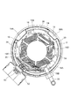
- FIG. 2 is a plan sectional view of the scroll compressor.
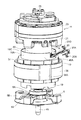
- FIG. 3 is a diagram showing an internal structure of a scroll compressor according to a modification.
- reference numeral 1 denotes a scroll compressor having an internal high pressure, and this compressor 1 is connected to a refrigerant circuit (not shown) that performs a refrigeration cycle operation by circulating the refrigerant, and compresses the refrigerant.
- the compressor 1 has a vertically long cylindrical hermetic dome-shaped casing 3.
- the casing 3 includes a casing main body 5 that is a cylindrical body having an axis extending in the vertical direction, and a bowl-shaped upper cap having a convex surface that is welded and integrally joined to the upper end of the casing body 5 7 and a flange-like lower cap 9 which is welded and integrally joined to the lower end portion of the casing body 5 and has a convex surface protruding downward, and is configured as a pressure vessel.
- a terminal cover 52 is provided on the outer peripheral surface of the casing 3, and a power supply terminal 53 that supplies power to a stator 37 described later is provided inside the terminal cover 52.
- a scroll compression mechanism 11 that compresses the refrigerant and a drive motor 13 that is disposed below the scroll compression mechanism 11.
- the scroll compression mechanism 11 and the drive motor 13 are connected to each other by a drive shaft 15 disposed so as to extend in the vertical direction in the casing 3.
- a gap space 17 is formed between the scroll compression mechanism 11 and the drive motor 13.
- a main frame 21 is accommodated in the upper part of the casing 3, and a radial bearing portion 28 and a boss accommodating portion 26 are formed in the center of the main frame 21.
- the radial bearing portion 28 is for supporting the tip (upper end) side of the drive shaft 15 and is formed to project downward from the center of one surface (lower surface) of the main frame 21.
- the boss accommodating portion 26 is for accommodating a boss 25C of the swing scroll 25 described later, and is formed by recessing the center of the other surface (upper surface) of the main frame 21 downward.
- An eccentric shaft portion 15 ⁇ / b> A is formed at the tip (upper end) of the drive shaft 15.
- the eccentric shaft portion 15 ⁇ / b> A is provided so that the center thereof is eccentric from the axis of the drive shaft 15, and is inserted into the boss 25 ⁇ / b> C via the turning bearing 24 so as to be capable of turning.
- the scroll compression mechanism 11 is composed of a fixed scroll 23 and a swing scroll 25.
- the fixed scroll 23 is disposed in close contact with the upper surface of the main frame 21.
- the main frame 21 is attached to the inner surface of the casing body 5, and the fixed scroll 23 is fixed to the main frame 21.
- the swing scroll 25 meshes with the fixed scroll 23 and is disposed in the swing space 12 formed between the fixed scroll 23 and the main frame 21.
- the casing 3 is partitioned into a high-pressure space 27 below the main frame 21 and a discharge space 29 above the main frame 21.
- the spaces 27 and 29 communicate with each other through vertical grooves 71 formed to extend vertically on the outer periphery of the main frame 21 and the fixed scroll 23.
- the upper cap 7 of the casing 3 has a suction pipe 31 that guides the refrigerant in the refrigerant circuit to the scroll compression mechanism 11, and the casing body 5 has a discharge pipe 33 that discharges the refrigerant in the casing 3 to the outside of the casing 3. It is fixed in a penetrating manner.
- the suction pipe 31 extends vertically in the discharge space 29, and an inner end thereof passes through the fixed scroll 23 of the scroll compression mechanism 11 and communicates with the compression chamber 35, and the refrigerant is introduced into the compression chamber 35 by the suction pipe 31. Is inhaled.
- the drive motor 13 is a DC (Direct Current) motor that is driven by receiving an input from a direct current power source, and includes an annular stator 37 and a rotor 39 that is configured to be rotatable inside the stator 37. Is provided.
- the drive motor 13 receives a constant input voltage, and its rotational torque is controlled by a PWM (Pulse Width Modulation) inverter that controls the duty ratio of the pulse wave, that is, the period for outputting the pulse wave and the pulse width when the pulse wave is output.
- PWM Pulse Width Modulation
- the drive motor 13 is a DC motor.
- the drive motor 13 may be an AC (Alternating Current) motor that is driven by receiving an input of an alternating current. good.
- the stator 37 includes a stator core 37 ⁇ / b> A and the stator coil 18.
- the stator core 37A is formed by stacking thin iron plates, and has a plurality of grooves inside although not shown.
- the stator coil 18 is formed by winding a plurality of phases of stator windings.
- the stator coil 18 is fitted into each groove formed in the stator core 37A and protrudes up and down the stator core 37A.
- Each stator coil 18 is accommodated in the insulator 19 above and below the stator core 37A.
- the stator coil 18 is connected to the power supply terminal 53 via a lead wire 20 (see FIG. 2) connecting the stator coils 18.
- the drive motor 13 rotates the rotor 39 by switching the stator coil 18 through which current flows.
- the rotor 39 is formed of a ferrite magnet or a neodymium magnet and is magnetized by magnetization.
- winding magnetization is performed by passing a current through the stator coil 18 of the stator 37 and magnetizing the rotor 39 or an external magnetizing device.
- There is external magnetization that is inserted into the stator 37 after being magnetized.
- a holder (pin holder) 58 used for positioning the rotor 39 when the rotor 39 is magnetized by winding is press-fitted inside the drive shaft 15.
- the stator 37 is supported on the inner wall surface of the casing 3 by an annular spacer ring 38.
- the spacer ring 38 is fixed to the inner wall surface of the casing 3 by shrink fitting, and the stator 37 is fixed to the inner wall surface of the spacer ring 38 by shrink fitting.
- the upper end surface of the spacer ring 38 is provided below the upper end surface of the stator 37.
- the bearing plate 8 that rotatably fits and supports the lower end portion of the drive shaft 15.
- the bearing plate 8 is formed in a cylindrical shape with a boss portion 8A into which the drive shaft 15 is inserted, and an arm portion 8B that is provided around the boss portion 8A at substantially equal intervals and extends in four directions and is fixed to the casing body 5. Is provided. That is, the drive shaft 15 is supported on the casing 3 by the bearing plate 8.
- the bearing plate 8 is formed between the arm portions 8B and has an opening 8E that communicates the upper and lower spaces.
- the baffle plate 14 is made of, for example, a thin plate-shaped punching metal having a large number of pores 14D.
- An oil supply passage 41 as a part of the high pressure oil supply means is formed in the drive shaft 15, and this oil supply passage 41 extends vertically inside the drive shaft 15 and enters an oil chamber 43 on the back surface of the swing scroll 25. Communicate.
- the oil supply path 41 is connected to an oil pickup 45 provided at the lower end of the drive shaft 15.
- a lateral hole 57 extending in the radial direction of the drive shaft 15 and penetrating the oil supply passage 41 is provided on the back side of the oil pickup 45.
- the holder 58 described above is press-fitted into the horizontal hole 57.
- the oil pickup 45 is press-fitted into the drive shaft 15 after the rotor 39 is magnetized.
- the oil pickup 45 includes a suction port 42 provided at the lower end and a paddle 44 formed above the suction port 42.
- the lower end of the oil pickup 45 is immersed in the lubricating oil (lubricating oil) stored in the oil sump 40, and the suction port 42 of the oil supply path 41 is opened in the lubricating oil.
- the lubricating oil stored in the oil sump 40 enters the oil supply passage 41 from the suction port 42 of the oil pickup 45 and is pumped upward along the paddle 44 of the oil supply passage 41.
- the pumped lubricating oil is supplied to the sliding portions of the scroll compression mechanism 11 such as the radial bearing 28 and the orbiting bearing 24 through the oil supply passage 41.
- the lubricating oil is supplied to the oil chamber 43 on the back of the orbiting scroll 25 through the oil supply passage 41, and is supplied from the oil chamber 43 to the compression chamber 35 through the communication path 51 provided in the orbiting scroll 25.
- the main frame 21 is formed with a return oil passage 47 that penetrates the main frame 21 in the radial direction from the boss accommodating portion 26 and opens into the vertical groove 71.
- a return oil passage 47 that penetrates the main frame 21 in the radial direction from the boss accommodating portion 26 and opens into the vertical groove 71.
- An oil collector 46 is provided below the return oil passage 47, and the oil collector 46 extends to the vicinity of the upper end of the spacer ring 38.
- a plurality of notches 54 are formed on the outer peripheral surface of the stator 37 so as to extend up and down the stator 37.
- Lubricating oil returned from the oil supply passage 41 through the return oil passage 47 and the oil collector 46 is returned to the oil sump 40 through the notches 54 and between the arm portions 8B of the bearing plate 8.
- the discharge pipe 33 is shown by a broken line for convenience of explanation, but the discharge pipe 33 is arranged out of phase with the oil collector 46.
- the fixed scroll 23 is composed of an end plate 23A and a spiral (involute) wrap 23B formed on the lower surface of the end plate 23A.
- the orbiting scroll 25 is composed of an end plate 25A and a spiral (involute) wrap 25B formed on the upper surface of the end plate 25A.
- the wrap 23B of the fixed scroll 23 and the wrap 25B of the swing scroll 25 are meshed with each other, so that a plurality of compression is performed between the fixed scroll 23 and the swing scroll 25 by the both wraps 23B and 25B.
- a chamber 35 is formed.
- the orbiting scroll 25 is supported by the fixed scroll 23 via the Oldham ring 61, and a bottomed cylindrical boss 25C projects from the center of the lower surface of the end plate 25A.
- an eccentric shaft portion 15 ⁇ / b> A is provided at the upper end of the drive shaft 15, and the eccentric shaft portion 15 ⁇ / b> A is rotatably fitted to a boss 25 ⁇ / b> C of the swing scroll 25.
- the drive shaft 15 is provided with a counterweight portion (upper balancer) 63 below the main frame 21, and a lower balancer 77 is provided below the rotor 39.
- the drive shaft 15 is dynamically balanced with the orbiting scroll 25, the eccentric shaft portion 15A, and the like by the upper balancer 63 and the lower balancer 77.
- the rocking scroll 25 is revolved by rotating the drive shaft 15 while balancing the weight by the counter weight portion 63 and the lower balancer 77.
- the compression chamber 35 is configured to compress the refrigerant sucked from the suction pipe 31 as the volume between the wraps 23B and 25B contracts toward the center.
- a lower plate of the lower balancer 77 is provided with a rotor 39 and a regulation plate 55 that is caulked together with the lower balancer 77.
- the restriction plate 55 is used to restrict the rotation of the rotor 39 when the rotor 39 is wound and magnetized.
- a cup 48 is fixed to the lower side of the main frame 21 with bolts 49 so as to surround the counterweight portion 63.
- the cup 48 prevents the lubricating oil leaking from the clearance between the main frame 21 and the drive shaft 15 from being scattered to the discharge pipe side due to the rotation of the counterweight part 63.
- a discharge hole 73 is provided in the central portion of the fixed scroll 23, and the gas refrigerant discharged from the discharge hole 73 is discharged to the discharge space 29 through the discharge valve 75, and the main frame 21 and the fixed scroll 23.
- the refrigerant flows out into the high-pressure space 27 below the main frame 21 through the vertical grooves 71 provided on the outer circumferences, and the high-pressure refrigerant is discharged out of the casing 3 through the discharge pipe 33 provided in the casing body 5.
- the scroll compressor 1 When the drive motor 13 is driven, the rotor 39 rotates with respect to the stator 37, and thereby the drive shaft 15 rotates.
- the swinging scroll 25 of the scroll compression mechanism 11 When the drive shaft 15 rotates, the swinging scroll 25 of the scroll compression mechanism 11 does not rotate with respect to the fixed scroll 23 but only revolves.
- the low-pressure refrigerant is sucked into the compression chamber 35 from the peripheral side of the compression chamber 35 through the suction pipe 31, and the refrigerant is compressed as the volume of the compression chamber 35 changes.
- the compressed refrigerant becomes high pressure and is discharged from the compression chamber 35 through the discharge valve 75 to the discharge space 29, and through the vertical grooves 71 provided on the outer circumferences of the main frame 21 and the fixed scroll 23.
- the refrigerant flows out into the high-pressure space 27 below the main frame 21, and the high-pressure refrigerant is discharged out of the casing 3 through a discharge pipe 33 provided in the casing body 5.
- the refrigerant discharged to the outside of the casing 3 circulates through a refrigerant circuit (not shown), and is again sucked into the compressor 1 through the suction pipe 31 and compressed, and the circulation of the refrigerant is repeated.
- the flow of the lubricating oil will be described.
- the lubricating oil stored in the inner bottom portion of the lower cap 9 in the casing 3 is sucked up by the oil pickup 45, and this lubricating oil passes through the oil supply passage 41 of the drive shaft 15 and the scroll compression mechanism 11.
- Each of the sliding parts and the compression chamber 35 are supplied.
- the excess lubricating oil in each sliding portion of the scroll compression mechanism 11 and the compression chamber 35 is collected from the return oil passage 47 to the oil collector 46 and passes through the notch 54 provided on the outer periphery of the stator 37. And returned to the lower side of the drive motor 13.
- the lubricating oil supplied to the radial bearing 30 through the oil supply passage 41 leaks from the lower end of the radial bearing portion 28, and the outer peripheral wall (peripheral wall) of the cup 48 by the rotation of the drive shaft 15 and the upper balancer 63. It is scattered on the 48A side.
- the lower (lower end) 48B of the cup 48 is opened.
- An insulator 19 that surrounds the stator coil 18 is provided on the upper surface of the stator 37, and the insulator 19 is formed in a double wall structure including an annular outer wall 19A and an inner wall 19B.
- the outer peripheral wall 48A of the cup 48 is closer to the inner side than the center C of the outer wall 19A and the inner wall 19B between the outer wall 19A and the inner wall 19B of the insulator 19 having a double wall structure, that is, the inner wall 19B side. And drooping. Further, the outer peripheral wall 48 of the cup 48, the outer wall 19A of the insulator 19, and the inner wall 19B are provided at positions separated from each other by a predetermined insulation distance or more.
- the lubricating oil that leaks from the lower end of the radial bearing portion 28 and is scattered to the outer peripheral wall 48A side of the cup 48 by the rotation of the drive shaft 15 and the upper balancer 63 passes through the outer peripheral wall 48A. It is dropped between the outer wall 19A and the inner wall 19B of the insulator 19. Thereby, it is possible to prevent the lubricating oil scattered by the rotation of the drive shaft 15 and the upper balancer 63 from being scattered to the discharge pipe 33 provided on the outer periphery of the casing 3. It is possible to prevent a large amount of lubricating oil leaking from the lower end from being discharged out of the casing 3 from the discharge pipe 33.
- the outer wall 19 ⁇ / b> A of the insulator 19 is formed higher than the inner wall 19 ⁇ / b> B, and the outer wall 19 ⁇ / b> A is formed so that the upper end 19 ⁇ / b> C extends to the vicinity of the lower end 48 ⁇ / b> A of the cup 48.
- the height of the outer wall 19A of the insulator 19 is set such that a gap g is provided between the upper end 19C and the lower end 48A of the cup 48 so that the upper end 19C is positioned slightly below the lower end 48A.
- the lubricating oil that leaks from the lower end of the radial bearing portion 28 and is scattered on the outer peripheral wall 48A side of the cup 48 by the rotation of the drive shaft 15 and the upper balancer 63 passes through the outer peripheral wall 48A. Even when the drive shaft 15 and the upper balancer 63 are rotated and dropped from the cup 48 obliquely downward when being dropped between the outer wall 19A and the inner wall 19B, the outer wall 19A of the insulator 19 is dropped. It is dripped inside.
- FIG. 2 is a plan sectional view of the scroll compression device cut above the drive motor 13.
- the drive shaft 15 and the rotor 39 are not shown in FIG.
- the lead wire 20 extending from the stator coil 18 is connected to the power supply terminal 53 through the upper side of the upper end 19 ⁇ / b> C of the insulator 19.
- Each stator coil 18 provided on the upper surface of the stator 37 is accommodated between an outer wall 19A and an inner wall 19B of an insulator 19 having a double wall structure.
- the stator 37 is provided with a notch 54 that communicates the space above and below the drive motor 13.
- a plurality of cutouts 38 ⁇ / b> A are formed on the outer periphery of the spacer ring 38 so as to extend above and below the spacer ring 38.
- the lubricating oil is returned from the upper side of the drive motor 13 to the lower side of the drive motor 13 through the notches 54 and the notches 38.
- the inner wall 19B and a plurality of walls 19D provided inside each stator coil 18 are configured, and a predetermined separation interval is provided between the adjacent walls 19D.
- the lubricating oil dropped between the outer wall 19A and the inner wall 19B of the insulator 19 may be discharged below the stator 37 through the gap between the walls constituting the inner wall 19B.
- FIG. 3 is a view showing a modification of the scroll compressor 1 shown in FIG.
- the height of the outer wall 19A of the insulator 19 is set so that the upper end 19C is positioned slightly below the lower end 48A of the cup 48, and the upper side of the upper end 19C of the outer wall 19A.
- the lead wire 20 is connected to the power supply terminal 53 through the through hole.
- the height of the outer wall 19 ⁇ / b> A of the insulator 19 is set so that the upper end 19 ⁇ / b> C is located above the lower end 48 ⁇ / b> A of the cup 48.
- a cutout 14 for drawing out the lead wire 20 extending from the stator coil 18 to the outside of the insulator 19 is provided on the outer wall 19A of the insulator 19. As shown in FIG. 3, the notch 14 is formed by partially cutting the outer wall 19A from above. The lead wire 20 drawn to the outside of the insulator 19 through the notch 14 is connected to the power supply terminal 53 using the connection terminal 20A. The notch 14 is provided in the vicinity of the notch 38 ⁇ / b> A formed over the spacer ring 38. The notch 14 is provided at a position away from the discharge pipe 33 in the circumferential direction.
- the lubricating oil that leaks from the lower end of the radial bearing portion 28 and is scattered by the rotation of the drive shaft 15 and the upper balancer 63 toward the outer peripheral wall 48 ⁇ / b> A side of the cup 48 is surely secured to the insulator 19. It can be dripped between the outer side wall 19 ⁇ / b> A and the inner side wall 19 ⁇ / b> B, and the lubricating oil can be prevented from being scattered on the discharge pipe 33 side provided on the outer periphery of the casing 3. As a result, a large amount of lubricating oil can be prevented from being discharged out of the casing 3 from the discharge pipe 33.
- the cut provided on the outer wall 19A is provided. Since the lead wire 20 can be drawn out of the insulator 19 from the notch 14, the insulation distance between the lead wire 20 and the cup 48 can be maintained.
- the scroll compression mechanism 11 that compresses the refrigerant inside the casing 3, the scroll compression mechanism 11 and the drive shaft 15 are connected to drive the scroll compression mechanism 11.
- the scroll compression mechanism 11 is supported by the casing 3 by the main frame 21, the stator 37 of the drive motor 13 is directly or indirectly supported by the casing 3, and the rotor 39 of the drive motor 13 is supported by the rotor 39.
- the drive shaft 15 is connected, the drive shaft 15 is supported by the casing 3 by the bearing plate 8, and a cup 48 having a lower opening for preventing splashing of lubricating oil is disposed on the lower surface of the main frame 21, and a stator 37.
- An insulator 19 having an annular double wall structure surrounding the winding is disposed on the upper surface of the cup 4. Since the peripheral wall 48A of is suspended insulator double walls 19A, during 19B, it is possible to collect leaked from the lubricating portions, the lubricating oil splashed by the rotation of the drive shaft 15 in the cup 48. Further, since the lubricating oil collected in the cup 48 is dropped between the double walls 19A and 19B of the insulator through the outer peripheral wall 48A of the cup 48, the lubricating oil is discharged outside the casing 3. It is possible to prevent scattering to the pipe 33 side, and it is possible to prevent a large amount of lubricating oil from being discharged from the discharge pipe 33.
- the peripheral wall 48A of the cup 18 is suspended inward from the center of the double walls 19A and 19B of the insulator 19, the outer peripheral wall 48A of the cup 48 is suspended. Even if the lubricating oil guided below the cup 48 scatters obliquely downward from the opening below the cup 48 due to the rotation of the drive shaft 15, the lubricating oil can be dripped inside the outer wall 19 ⁇ / b> A of the insulator 19. Further, it is possible to prevent the lubricating oil from being scattered toward the discharge pipe 33 disposed outside the casing 3, and to prevent a large amount of the lubricating oil from being discharged from the discharge pipe 33.
- the outer wall 19A of the double wall of the insulator 19 is formed higher than the inner wall 19B.
- Lubricating oil that scatters to the side can be more effectively dropped onto the inside of the outer wall 19 ⁇ / b> A of the insulator 19.
- the upper end of the outer wall 19A of the double wall of the insulator 19 extends to a height near the lower end of the cup.
- Lubricating oil that scatters diagonally downward from the opening can be more reliably dropped onto the inner side of the outer wall 19A of the insulator 19. Thereby, it is possible to prevent the lubricating oil from being scattered to the side of the discharge pipe 33 disposed outside the casing 3 and to prevent a large amount of the lubricating oil from being discharged from the discharge pipe 33.
- the notch 14 for drawing out the lead wire 20 of the winding is provided on the outer wall 19A of the double wall of the insulator 19, the lead is provided from the notch 14 provided on the outer wall 19A.
- the wire 20 can be pulled out to the outside of the insulator 19 and the insulation distance between the lead wire 20 and the cup 48 can be maintained.
- the drive motor 13 is a DC drive motor that is driven with a rotational torque controlled by a PWM inverter. Miniaturization can be achieved, and further, driving by an inverter can prevent generation of useless heat due to increase / decrease of the voltage of the drive motor 13 and improve drive efficiency.
Landscapes
- Engineering & Computer Science (AREA)
- Mechanical Engineering (AREA)
- General Engineering & Computer Science (AREA)
- Rotary Pumps (AREA)
- Applications Or Details Of Rotary Compressors (AREA)
Abstract
吐出管側への潤滑オイルの飛散を防止するスクロール圧縮装置を提供する。 メインフレーム21の下面に潤滑油の飛散防止用の下方が開放されたカップ48が配置されると共に、ステータ37の上面に巻き線を囲う環状の二重壁構造のインシュレータ19が配置され、カップ48の周壁がインシュレータの二重壁19A、19Bの間に垂下されている。
Description
本発明は、固定スクロールと揺動スクロールの噛み合い部に潤滑オイルを供給し、固定スクロールと揺動スクロールの噛み合いにより圧縮を行うスクロール圧縮装置に関する。
従来、密閉されたケーシング内に、互いに噛合する渦巻き状のラップを有する固定スクロールと揺動スクロールとからなる圧縮機構を備え、この圧縮機構を駆動モータで駆動させて、固定スクロールに対して揺動スクロールを自転することなく円運動させることにより圧縮を行うスクロール圧縮装置が知られている(例えば、特許文献1参照)。
この種のスクロール圧縮装置では、吸入管から吸引した低圧の冷媒を圧縮機構で圧縮し、圧縮された高圧冷媒をケーシングに設けた吐出管からケーシング外に吐出する。また、圧縮機構の各摺動部分、及び、固定スクロールと揺動スクロールの噛み合い部等の潤滑部位には、潤滑オイルが供給される。供給する潤滑オイルは、ケーシング下部に設けられた油溜めに貯留され、各潤滑部位で過剰となり、漏出した潤滑オイルは、自重で油溜めに戻される構成となっている。また、揺動スクロールは、駆動モータの駆動軸の軸心から偏心して設けられた偏心軸部に挿嵌される。そのため、スクロール圧縮装置では、一般的に、揺動スクロールの円運動に伴う遠心力に対向する上バランサを駆動軸の駆動モータ上方に設けている。
この種のスクロール圧縮装置では、吸入管から吸引した低圧の冷媒を圧縮機構で圧縮し、圧縮された高圧冷媒をケーシングに設けた吐出管からケーシング外に吐出する。また、圧縮機構の各摺動部分、及び、固定スクロールと揺動スクロールの噛み合い部等の潤滑部位には、潤滑オイルが供給される。供給する潤滑オイルは、ケーシング下部に設けられた油溜めに貯留され、各潤滑部位で過剰となり、漏出した潤滑オイルは、自重で油溜めに戻される構成となっている。また、揺動スクロールは、駆動モータの駆動軸の軸心から偏心して設けられた偏心軸部に挿嵌される。そのため、スクロール圧縮装置では、一般的に、揺動スクロールの円運動に伴う遠心力に対向する上バランサを駆動軸の駆動モータ上方に設けている。
しかしながら、各潤滑部位から漏出する潤滑オイルは、駆動軸、及び、上バランサの回転によってケーシングの外周方向に向かってケーシングの外側に設けられた吐出管側へ飛散される。吐出管側へ潤滑オイルが飛散すると、吐出管からケーシング外に多量に潤滑オイルが吐出するという問題がある。
本発明は、上述した従来の技術が有する課題を解消し、吐出管側への潤滑オイルの飛散を防止するスクロール圧縮装置を提供することを目的とする。
本発明は、上述した従来の技術が有する課題を解消し、吐出管側への潤滑オイルの飛散を防止するスクロール圧縮装置を提供することを目的とする。
上記目的を達成するために、本発明は、ケーシングの内部に冷媒を圧縮するスクロール圧縮機構と、前記スクロール圧縮機構と駆動軸で連結され当該スクロール圧縮機構を駆動する駆動モータとが収容され、前記スクロール圧縮機構がメインフレームにより前記ケーシングに支持され、前記駆動モータのステータが直接的または間接的に前記ケーシングに支持され、前記駆動モータのロータに前記駆動軸が連結され、当該駆動軸がベアリングプレートにより前記ケーシングに支持され、前記メインフレームの下面に潤滑油の飛散防止用の下方が開放されたカップが配置されると共に、前記ステータの上面に巻き線を囲う環状の二重壁構造のインシュレータが配置され、前記カップの周壁が前記インシュレータの二重壁の間に垂下されていることを特徴とする。
この発明では、潤滑油の飛散がカップで防止されると共に、カップの周壁側に飛散された潤滑油は、カップ周壁をつたってインシュレータの二重壁の間に滴下する。これによって、潤滑油が吐出管側へ飛散するのを防止することができる。
この発明では、潤滑油の飛散がカップで防止されると共に、カップの周壁側に飛散された潤滑油は、カップ周壁をつたってインシュレータの二重壁の間に滴下する。これによって、潤滑油が吐出管側へ飛散するのを防止することができる。
この構成において、前記カップの周壁が前記インシュレータの二重壁の中心より内方寄りに垂下されている構成としても良い。また、前記インシュレータの二重壁の外側壁が内側壁より高く形成されている構成としても良い。また、前記インシュレータの二重壁の外側壁の上端は、前記カップの下端近傍の高さに延在する構成としても良い。また、前記インシュレータの二重壁の外側壁に前記巻き線のリード線を引き出す切欠きを設けた構成としても良い。また、前記駆動モータは、インバータによって駆動するDC駆動モータである構成としても良い。
本発明によれば、メインフレームの下面に潤滑油の飛散防止用の下方が開放されたカップが配置されると共に、ステータの上面に巻き線を囲う環状の二重壁構造のインシュレータが配置され、カップの周壁がインシュレータの二重壁の間に垂下されるため、潤滑油は、カップの周壁側に飛散し、カップの周壁側に飛散した潤滑油は、カップの周壁をつたってインシュレータの二重壁の間に滴下するため、潤滑油が吐出管側へ飛散するのを防止することができる。
以下、本発明の一実施の形態を図面に基づいて説明する。
図1において、1は内部高圧となるスクロール圧縮装置を示し、この圧縮機1は、冷媒が循環して冷凍サイクル運転動作を行う図外の冷媒回路に接続されて、冷媒を圧縮するものである。この圧縮機1は、縦長円筒状の密閉ドーム型のケーシング3を有する。
このケーシング3は、上下方向に延びる軸線を有する円筒状の胴部であるケーシング本体5と、その上端部に気密状に溶接されて一体接合され、上方に突出した凸面を有する椀状の上キャップ7と、ケーシング本体5の下端部に気密状に溶接されて一体接合され、下方に突出した凸面を有する椀状の下キャップ9とで圧力容器に構成されており、その内部は空洞とされている。ケーシング3の外周面には、ターミナルカバー52が設けられ、このターミナルカバー52の内部には、後述のステータ37に電源を供給する電源供給端子53が備えられる。
ケーシング3の内部には、冷媒を圧縮するスクロール圧縮機構11と、このスクロール圧縮機構11の下方に配置される駆動モータ13とが収容されている。これらのスクロール圧縮機構11と駆動モータ13とは、ケーシング3内を上下方向に延びるように配置される駆動軸15によって連結されている。また、これらのスクロール圧縮機構11と駆動モータ13との間には間隙空間17が形成されている。
ケーシング3の内部上方には、メインフレーム21が収納され、このメインフレーム21には中央にラジアル軸受部28とボス収容部26とが形成されている。ラジアル軸受部28は、駆動軸15の先端(上端)側を軸支するためのものであり、当該メインフレーム21の一方の面(下側の面)の中央から下方に突出して形成されている。ボス収容部26は後述する揺動スクロール25のボス25Cを収容するためのものであり、メインフレーム21の他方の面(上側の面)の中央を下方に凹陥することにより形成されている。駆動軸15の先端(上端)には、偏心軸部15Aが形成されている。この偏心軸部15Aは、中心が駆動軸15の軸心と偏心して設けられると共に、旋回軸受け24を介して、ボス25Cに旋回駆動可能に挿入されている。
上記スクロール圧縮機構11は、固定スクロール23と揺動スクロール25とで構成されている。固定スクロール23は、メインフレーム21の上面に密着して配置される。メインフレーム21は、ケーシング本体5の内面に取り付けられ、固定スクロール23は、メインフレーム21に固定されている。揺動スクロール25は、固定スクロール23に噛合し、固定スクロール23と、メインフレーム21との間の形成される揺動空間12内に配置される。ケーシング3内は、メインフレーム21の下方の高圧空間27と、メインフレーム21の上方の吐出空間29とに区画される。各空間27,29は、メインフレーム21及び固定スクロール23の外周に縦に延びて形成された縦溝71を介して連通している。
ケーシング3の上キャップ7には、冷媒回路の冷媒をスクロール圧縮機構11に導く吸入管31が、またケーシング本体5には、ケーシング3内の冷媒をケーシング3外に吐出させる吐出管33がそれぞれ気密状に貫通固定されている。吸入管31は、吐出空間29を上下方向に延び、その内端部はスクロール圧縮機構11の固定スクロール23を貫通して、圧縮室35に連通し、この吸入管31により圧縮室35内に冷媒が吸入される。
駆動モータ13は、本実施形態では、直流電源からの入力を受けて駆動するDC(Direct Current)モータであり、環状のステータ37と、このステータ37の内側に回転自在に構成されたロータ39とを備える。駆動モータ13は、一定の入力電圧を受け、パルス波のデューティ比、つまり、パルス波を出す周期と出した時のパルス幅と、を制御するPWM(Pulse Width Modulation)インバータによって回転トルクが制御され駆動する。本実施形態では、駆動モータ13は、DCモータである構成としたが、この他に、駆動モータ13は、交流電流の入力をうけて駆動するAC(Alternating Current)モータである構成であっても良い。
ロータ39には、駆動軸15を介してスクロール圧縮機構11の揺動スクロール25が駆動連結されている。ステータ37は、ステータコア37Aと、ステータコイル18とから成る。ステータコア37Aは、薄い鉄板を重ね合わせて形成され、内部には、図示は省略したが、複数の溝を有する。ステータコイル18は、複数相のステータ巻き線が巻回されて形成され、ステータコア37Aの内部に形成された各溝に嵌入されて、ステータコア37Aの上下に突出して備えられる。各ステータコイル18は、ステータコア37Aの上下で、インシュレータ19の内部に収容されている。ステータコイル18は、各ステータコイル18を連結するリード線20(図2参照)を介して電源供給端子53に接続される。駆動モータ13は、電流を流すステータコイル18を切り替えることによってロータ39を回転させる。
ロータ39は、フェライト磁石、或いは、ネオジウム磁石から形成され着磁によって磁化される。ロータ39を磁化させる方法としては、ロータ39をステータ37に内挿した後、ステータ37のステータコイル18に電流を流して着磁する巻線着磁、或いは、ロータ39を外部の着磁装置を用いて着磁させた後にステータ37に内挿する外部着磁がある。駆動軸15の内部には、ロータ39の巻線着磁を行う際に、ロータ39の位置決めに用いる、ホルダ(ピンホルダ)58が圧入されている。
ステータ37は、環状のスペーサリング38によってケーシング3の内壁面に支持される。スペーサリング38はケーシング3の内壁面に焼き嵌めによって固定され、ステータ37はスペーサリング38の内壁面に焼き嵌めによって固定される。スペーサリング38の上端面は、ステータ37の上端面よりも下方に設けられる。
ステータ37は、環状のスペーサリング38によってケーシング3の内壁面に支持される。スペーサリング38はケーシング3の内壁面に焼き嵌めによって固定され、ステータ37はスペーサリング38の内壁面に焼き嵌めによって固定される。スペーサリング38の上端面は、ステータ37の上端面よりも下方に設けられる。
駆動モータ13の下方には、駆動軸15の下端部を回転可能に嵌入支持するベアリングプレート8が備えられる。ベアリングプレート8は、円筒状に形成され駆動軸15が嵌入されるボス部8Aと、このボス部8Aに略等間隔に周設され4方向に延び、ケーシング本体5に固定されるアーム部8Bとを備える。つまり、駆動軸15は、ベアリングプレート8によってケーシング3に支持される。ベアリングプレート8は、各アーム部8Bの間に形成され、上下の空間を連通する開口部8Eを有する。
図1に示す、ベアリングプレート8の下方の下部空間(油溜め)40は、高圧に保たれており、その下端部に相当する下キャップ9の内底部には油が貯留される。ベアリングプレート8と、油溜め40の間には、環状プレート59がベアリングプレート8に固定されて備えられる。また、環状プレート59の上方には、バッフル板14が環状プレート59に支持されて設けられる。バッフル板14は、例えば、多数の細孔14Dを有した、例えば薄板状のパンチングメタルによって形成される。
図1に示す、ベアリングプレート8の下方の下部空間(油溜め)40は、高圧に保たれており、その下端部に相当する下キャップ9の内底部には油が貯留される。ベアリングプレート8と、油溜め40の間には、環状プレート59がベアリングプレート8に固定されて備えられる。また、環状プレート59の上方には、バッフル板14が環状プレート59に支持されて設けられる。バッフル板14は、例えば、多数の細孔14Dを有した、例えば薄板状のパンチングメタルによって形成される。
駆動軸15内には、高圧油供給手段の一部としての給油路41が形成され、この給油路41は、駆動軸15の内部を上下に延び、揺動スクロール25の背面の油室43に連通している。この給油路41は、駆動軸15の下端に設けたオイルピックアップ45に連結される。オイルピックアップ45の奥側には、駆動軸15の径方向に延び、給油路41を貫通する横穴57が設けられる。この横穴57には、上述したホルダ58が圧入される。オイルピックアップ45は、ロータ39の着磁後に、駆動軸15に圧入される。
オイルピックアップ45は、下端に設けられた吸込口42と、この吸込口42の上方に形成されたパドル44とを備える。オイルピックアップ45の下端は、油溜め40に貯留された潤滑オイル(潤滑油)に浸漬されて、当該給油路41の吸込口42が潤滑オイル内にて開口している。駆動軸15が回転すると、油溜め40に貯留された潤滑オイルがオイルピックアップ45の吸込口42から給油路41に入り、この給油路41のパドル44に沿って上方に汲み上げられる。そして、汲み上げられた潤滑オイルは、給油路41を通じ、ラジアル軸受部28、及び、旋回軸受24等のスクロール圧縮機構11の各摺動部分に供給される。さらに、潤滑オイルは、給油路41を通じて揺動スクロール25背面の油室43に供給され、この油室43から、揺動スクロール25に設けられた連通路51を介して、圧縮室35へ供給される。
メインフレーム21には、ボス収容部26からメインフレーム21を径方向に貫通し、縦溝71に開口する戻し油路47が形成される。給油路41を通じ、スクロール圧縮機構11の各摺動部分、及び、圧縮室35に供給される潤滑オイルのうち、過剰となった潤滑オイルは、この戻し油路47を通って油溜め40に戻される。戻し油路47の下方には、オイルコレクター46が設けられ、オイルコレクター46は、スペーサリング38の上端近傍まで延在する。ステータ37の外周面には、ステータ37の上下に亘る複数の切欠き54が形成される。戻し油路47、オイルコレクター46を通じて給油路41から戻された潤滑オイルは、この切欠き54、及び、ベアリングプレート8の各アーム部8Bの間を通って油溜め40に戻される。なお、図1の断面図において、吐出管33が説明の便宜上破線で示されているが、吐出管33は、オイルコレクター46とは、位相をずらして配置される。
固定スクロール23は、鏡板23Aと、この鏡板23Aの下面に形成された渦巻き状(インボリュート状)のラップ23Bとで構成されている。一方、揺動スクロール25は、鏡板25Aと、この鏡板25Aの上面に形成された渦巻き状(インボリュート状)のラップ25Bとで構成されている。そして、固定スクロール23のラップ23Bと、揺動スクロール25のラップ25Bとは互いに噛合しており、このことにより固定スクロール23と揺動スクロール25との間において、両ラップ23B,25Bで複数の圧縮室35が形成されている。
揺動スクロール25は、オルダムリング61を介して固定スクロール23に支持され、その鏡板25Aの下面の中心部には有底円筒状のボス25Cが突設されている。一方、駆動軸15の上端には偏心軸部15Aが設けられ、この偏心軸部15Aは、揺動スクロール25のボス25Cに回転可能に嵌入されている。
さらに、駆動軸15には、メインフレーム21の下側に、カウンタウェイト部(上バランサ)63が設けられ、ロータ39の下部には、下バランサ77が設けられている。駆動軸15は、これらの上バランサ63、及び、下バランサ77によって揺動スクロール25や偏心軸部15A等と動的バランスを取っている。
さらに、駆動軸15には、メインフレーム21の下側に、カウンタウェイト部(上バランサ)63が設けられ、ロータ39の下部には、下バランサ77が設けられている。駆動軸15は、これらの上バランサ63、及び、下バランサ77によって揺動スクロール25や偏心軸部15A等と動的バランスを取っている。
これらのカウンタウェイト部63、及び、下バランサ77により重さのバランスを取りながら駆動軸15が回転することで、揺動スクロール25を公転させるようになっている。そして、この揺動スクロール25の公転に伴い、圧縮室35は、両ラップ23B,25B間の容積が中心に向かって収縮することで吸入管31より吸入された冷媒を圧縮するように構成されている。また、下バランサ77の下面には、ロータ39、及び、下バランサ77と一体にカシメられる規制プレート55が設けられる。規制プレート55は、ロータ39の巻線着磁を行う際に、ロータ39の回転を規制するために用いられる。
メインフレーム21の下側には、カウンタウェイト部63の周りを囲うようにカップ48がボルト49で固定されている。カップ48は、メインフレーム21と、駆動軸15との間のクリアランスから漏れ出た潤滑オイルが、カウンタウェイト部63の回転によって吐出管側に飛散されるのを防ぐ。
固定スクロール23の中央部には吐出孔73が設けられており、この吐出孔73から吐出されたガス冷媒は、吐出弁75を通って吐出空間29に吐出され、メインフレーム21及び固定スクロール23の各外周に設けた縦溝71を介して、メインフレーム21の下方の高圧空間27に流出し、この高圧冷媒は、ケーシング本体5に設けた吐出管33を介してケーシング3外に吐出される。
このスクロール圧縮装置1の運転動作について説明する。
駆動モータ13を駆動すると、ステータ37に対してロータ39が回転し、それによって駆動軸15が回転する。駆動軸15が回転すると、スクロール圧縮機構11の揺動スクロール25が固定スクロール23に対して自転せずに公転のみ行う。このことにより、低圧の冷媒が吸入管31を通して圧縮室35の周縁側から圧縮室35に吸引され、この冷媒は圧縮室35の容積変化に伴って圧縮される。そして、この圧縮された冷媒は、高圧となって圧縮室35から吐出弁75を通って吐出空間29に吐出され、メインフレーム21及び固定スクロール23の各外周に設けた縦溝71を介して、メインフレーム21の下方の高圧空間27に流出し、この高圧冷媒は、ケーシング本体5に設けた吐出管33を介してケーシング3外に吐出される。ケーシング3外に吐出された冷媒は、図示を省略した冷媒回路を循環した後、再度吸入管31を通して圧縮機1に吸入されて圧縮され、このような冷媒の循環が繰り返される。
駆動モータ13を駆動すると、ステータ37に対してロータ39が回転し、それによって駆動軸15が回転する。駆動軸15が回転すると、スクロール圧縮機構11の揺動スクロール25が固定スクロール23に対して自転せずに公転のみ行う。このことにより、低圧の冷媒が吸入管31を通して圧縮室35の周縁側から圧縮室35に吸引され、この冷媒は圧縮室35の容積変化に伴って圧縮される。そして、この圧縮された冷媒は、高圧となって圧縮室35から吐出弁75を通って吐出空間29に吐出され、メインフレーム21及び固定スクロール23の各外周に設けた縦溝71を介して、メインフレーム21の下方の高圧空間27に流出し、この高圧冷媒は、ケーシング本体5に設けた吐出管33を介してケーシング3外に吐出される。ケーシング3外に吐出された冷媒は、図示を省略した冷媒回路を循環した後、再度吸入管31を通して圧縮機1に吸入されて圧縮され、このような冷媒の循環が繰り返される。
潤滑オイルの流れを説明すると、ケーシング3における下キャップ9の内底部に貯留された潤滑オイルが、オイルピックアップ45により吸い上げられ、この潤滑オイルが、駆動軸15の給油路41を通じ、スクロール圧縮機構11の各摺動部分、及び、圧縮室35へ供給される。スクロール圧縮機構11の各摺動部分、及び、圧縮室35で過剰となった潤滑オイルは、戻し油路47から、オイルコレクター46に集められ、ステータ37の外周に設けられた切欠き54を通って駆動モータ13の下方に戻される。
また、給油路41を通ってラジアル軸受30に供給された潤滑オイルは、ラジアル軸受部28の下端から漏れ出て、駆動軸15、及び、上バランサ63の回転によってカップ48の外周壁(周壁)48A側に飛散される。カップ48は、下方(下端)48Bが開放されている。ステータ37の上面には、ステータコイル18を囲う、インシュレータ19が設けられ、インシュレータ19は、環状の外側壁19Aと内側壁19Bとかなる二重壁構造に形成されている。カップ48の外周壁48Aは、二重壁構造のインシュレータ19の外側壁19Aと内側壁19Bとの間で、外側壁19Aと内側壁19Bの中心Cよりも、内方寄り、つまり内側壁19B側に寄せて、垂下されている。また、カップ48の外周壁48と、インシュレータ19の外側壁19A、及び、内側壁19Bとは、それぞれ所定以上の絶縁距離を離した位置に設けられる。
この構成によれば、ラジアル軸受部28の下端から漏れ出て、駆動軸15、及び、上バランサ63の回転によってカップ48の外周壁48A側に飛散された潤滑オイルは、外周壁48Aをつたってインシュレータ19の外側壁19Aと内側壁19Bとの間に滴下される。これによって、駆動軸15、及び、上バランサ63の回転によって飛散された潤滑オイルがケーシング3の外周に設けられた吐出管33側に飛散されるのを防止することができ、ラジアル軸受部28の下端から漏出した潤滑オイルが吐出管33から多量にケーシング3外に吐出されるのを防ぐことができる。
インシュレータ19の外側壁19Aは、内側壁19Bよりも高く形成され、外側壁19Aは、上端19Cが、カップ48の下端48Aの近傍まで延在する高さに形成されている。インシュレータ19の外側壁19Aの高さは、上端19Cと、カップ48の下端48Aとの間にギャップgを設けて、上端19Cが下端48Aよりも僅かに下側に位置するように設定される。
この構成よれば、ラジアル軸受部28の下端から漏れ出て、駆動軸15、及び、上バランサ63の回転によってカップ48の外周壁48A側に飛散された潤滑オイルが、外周壁48Aをつたってインシュレータ19の外側壁19Aと内側壁19Bとの間に滴下されるさいに、駆動軸15、及び、上バランサ63の回転によってカップ48から斜め下方に向かって飛散されても、インシュレータ19の外側壁19Aの内側に滴下される。これによってケーシング3の外周に設けられた吐出管33側に潤滑オイルが飛散するのを防ぐことができ、吐出管33から多量の潤滑オイルがケーシング3外に吐出されるのを防止することができる。
図2は、スクロール圧縮装置を駆動モータ13の上方で切断した平面断面図であり、駆動軸15、及び、ロータ39は、この図2では、不図示とした。図2に示すように、ステータコイル18から延びるリード線20は、インシュレータ19の上端19Cの上側を通って電源供給端子53に接続される。ステータ37の上面に設けられた各ステータコイル18は、二重壁構造のインシュレータ19の外側壁19Aと内側壁19Bとの間に収容されている。
ステータ37には、駆動モータ13の上下の空間を連通させる切欠き54が設けられる。また、スペーサリング38の外周には、スペーサリング38の上下に亘る複数の切欠き38Aが形成される。潤滑オイルは、駆動モータ13の上側から、これらの切欠き54、及び切欠き38を介して、駆動モータ13の下側に戻される。
ステータ37には、駆動モータ13の上下の空間を連通させる切欠き54が設けられる。また、スペーサリング38の外周には、スペーサリング38の上下に亘る複数の切欠き38Aが形成される。潤滑オイルは、駆動モータ13の上側から、これらの切欠き54、及び切欠き38を介して、駆動モータ13の下側に戻される。
また、内側壁19B、各ステータコイル18の内側に設けられた複数の壁19Dから構成され、隣合う壁19Dの間には、所定の離隔間隔が空けられている。インシュレータ19の外側壁19Aと内側壁19Bとの間に滴下された潤滑オイルは、この内側壁19Bを構成する各壁間の間隙からステータ37の下方に排出される構成であっても良い。
図3は、図1で示したスクロール圧縮装置1の変形例を示す図である。上述のスクロール圧縮装置1では、インシュレータ19の外側壁19Aの高さを、上端19Cが、カップ48の下端48Aよりも僅かに下側に位置するように設定し、外側壁19Aの上端19Cの上側を通してリード線20を電源供給端子53に接続する構成とした。図3に示した変形例では、インシュレータ19の外側壁19Aの高さを上端19Cが、カップ48の下端48Aよりも上側に位置するように設定した。また、インシュレータ19の外側壁19Aに、ステータコイル18から延びるリード線20をインシュレータ19の外側に引き出すための切欠き14を設けた。切欠き14は、図3に示すように、外側壁19Aを上方から一部切り欠いて形成される。この切欠き14を介してインシュレータ19の外側に引き出されたリード線20は、接続端子20Aを用いて電源供給端子53に接続される。切欠き14は、スペーサリング38の上下に亘って形成された切欠き38Aの近傍に設けられる。また、切欠き14は、吐出管33からは周方向に離れた位置に設けられる。
この構成によれば、ラジアル軸受部28の下端から漏れ出て、駆動軸15、及び、上バランサ63の回転によってカップ48の外周壁48A側に飛散された潤滑オイルを、確実に、インシュレータ19の外側壁19Aと内側壁19Bとの間に滴下することができ、潤滑オイルがケーシング3の外周に設けられた吐出管33側に飛散されるのを防止することができる。これによって、潤滑オイルが吐出管33から多量にケーシング3外に吐出されるのを防ぐことができる。
また、この構成によれば、インシュレータ19の外側壁19Aの上端19Cが、カップ48の下端48Aより上側に位置するように外側壁19Aの高さを設定しても、外側壁19Aに設けた切欠き14からリード線20をインシュレータ19の外側に引き出すことができるため、リード線20とカップ48との絶縁距離を保つことができる。
以上説明したように、本発明を適用した実施形態によれば、ケーシング3の内部に冷媒を圧縮するスクロール圧縮機構11と、スクロール圧縮機構11と駆動軸15で連結され当該スクロール圧縮機構11を駆動する駆動モータ13とが収容され、スクロール圧縮機構11がメインフレーム21によりケーシング3に支持され、駆動モータ13のステータ37が直接的または間接的にケーシング3に支持され、駆動モータ13のロータ39に駆動軸15が連結され、当該駆動軸15がベアリングプレート8によりケーシング3に支持され、メインフレーム21の下面に潤滑油の飛散防止用の下方が開放されたカップ48が配置されると共に、ステータ37の上面に巻き線を囲う環状の二重壁構造のインシュレータ19が配置され、カップ48の周壁48Aがインシュレータの二重壁19A,19Bの間に垂下されているため、各潤滑部位から漏出し、駆動軸15の回転によって飛散する潤滑オイルをカップ48で集めることができる。また、カップ48に集められた潤滑オイルは、カップ48の外周壁48Aをつたって、インシュレータの二重壁19A,19Bの間に滴下されるため、潤滑オイルがケーシング3の外側に配置された吐出管33側へ飛散されるのを防ぐことができ、吐出管33から多量の潤滑オイルが吐出されるのを防ぐことができる。
また、本発明を適用した実施形態によれば、カップ18の周壁48Aがインシュレータ19の二重壁19A,19Bの中心より内方寄りに垂下されているため、カップ48の外周壁48Aをつたってカップ48の下方に導かれる潤滑オイルが、駆動軸15の回転によってカップ48の下方の開口から斜め下側に飛散しても、インシュレータ19の外側壁19Aの内側に潤滑オイルを滴下することができ、潤滑オイルがケーシング3の外側に配置された吐出管33側へ飛散されるのを防ぐことができ、吐出管33から多量の潤滑オイルが吐出されるのを防ぐことができる。
また、本発明を適用した実施形態によれば、インシュレータ19の二重壁の外側壁19Aが内側壁19Bより高く形成されているため、駆動軸15の回転によってカップ48の下方の開口から斜め下側に飛散する潤滑オイルを、より効果的にインシュレータ19の外側壁19Aの内側に滴下することができる。これによって、潤滑オイルがケーシング3の外側に配置された吐出管33側へ飛散されるのを防ぐことができ、吐出管33から多量の潤滑オイルが吐出されるのを防ぐことができる。
また、本発明を適用した実施形態によれば、インシュレータ19の二重壁の外側壁19Aの上端は、カップの下端近傍の高さに延在するため、駆動軸15の回転によってカップ48の下方の開口から斜め下側に飛散する潤滑オイルを、より確実にインシュレータ19の外側壁19Aの内側に滴下することができる。これによって、潤滑オイルがケーシング3の外側に配置された吐出管33側へ飛散されるのを防ぐことができ、吐出管33から多量の潤滑オイルが吐出されるのを防ぐことができる。
また、本発明を適用した実施形態によれば、インシュレータ19の二重壁の外側壁19Aに巻き線のリード線20を引き出す切欠き14を設けたため、外側壁19Aに設けた切欠き14からリード線20をインシュレータ19の外側に引き出すことができ、リード線20とカップ48との絶縁距離を保つことができる。
また、本発明を適用した実施形態によれば、駆動モータ13は、PWMインバータによって回転トルクが制御され駆動するDC駆動モータであるため、出力効率の良い駆動モータを用いることで、駆動モータ13の小型化を図ることができ、さらに、インバータによって駆動させることで、駆動モータ13の電圧の上昇/下降による無駄な熱の発生を防ぎ、駆動効率をよくすることができる。
1 スクロール圧縮装置
3 ケーシング
11 スクロール圧縮機構
13 駆動モータ
14 リード線切欠き
19 インシュレータ
19A 外側壁
19B 内側壁
20 リード線
21 メインフレーム
37 ステータ
39 ロータ
48 カップ
48A 周壁(外周壁)
3 ケーシング
11 スクロール圧縮機構
13 駆動モータ
14 リード線切欠き
19 インシュレータ
19A 外側壁
19B 内側壁
20 リード線
21 メインフレーム
37 ステータ
39 ロータ
48 カップ
48A 周壁(外周壁)
Claims (6)
- ケーシングの内部に冷媒を圧縮するスクロール圧縮機構と、前記スクロール圧縮機構と駆動軸で連結され当該スクロール圧縮機構を駆動する駆動モータとが収容され、
前記スクロール圧縮機構がメインフレームにより前記ケーシングに支持され、
前記駆動モータのステータが直接的または間接的に前記ケーシングに支持され、
前記駆動モータのロータに前記駆動軸が連結され、当該駆動軸がベアリングプレートにより前記ケーシングに支持され、
前記メインフレームの下面に潤滑油の飛散防止用の下方が開放されたカップが配置されると共に、前記ステータの上面にステータコイルを囲う環状の二重壁構造のインシュレータが配置され、前記カップの周壁が前記インシュレータの二重壁の間に垂下されていることを特徴とするスクロール圧縮装置。 - 前記カップの周壁が前記インシュレータの二重壁の中心より内方寄りに垂下されていることを特徴とする請求項1に記載のスクロール圧縮装置。
- 前記インシュレータの二重壁の外側壁が内側壁より高く形成されていることを特徴とする請求項1または2に記載のスクロール圧縮装置。
- 前記インシュレータの二重壁の外側壁の上端は、前記カップの下端近傍の高さに延在することを特徴とする請求項3に記載のスクロール圧縮装置。
- 前記インシュレータの二重壁の外側壁に前記ステータコイルのリード線を引き出す切欠きを設けたことを特徴とする請求項1から4のいずれかに記載のスクロール圧縮装置。
- 前記駆動モータは、インバータによって駆動するDC駆動モータであることを特徴とする請求項1から5のいずれかに記載のスクロール圧縮装置。
Priority Applications (1)
| Application Number | Priority Date | Filing Date | Title |
|---|---|---|---|
| US14/007,181 US9494155B2 (en) | 2011-03-24 | 2011-12-20 | Scroll compression device |
Applications Claiming Priority (14)
| Application Number | Priority Date | Filing Date | Title |
|---|---|---|---|
| JP2011-065607 | 2011-03-24 | ||
| JP2011065607A JP2012202252A (ja) | 2011-03-24 | 2011-03-24 | スクロール圧縮装置 |
| JP2011-067051 | 2011-03-25 | ||
| JP2011-066920 | 2011-03-25 | ||
| JP2011-066921 | 2011-03-25 | ||
| JP2011066920A JP2012202277A (ja) | 2011-03-25 | 2011-03-25 | スクロール圧縮装置 |
| JP2011066921A JP2012202278A (ja) | 2011-03-25 | 2011-03-25 | スクロール圧縮装置、及び、スクロール圧縮装置の着磁方法 |
| JP2011067051A JP5824668B2 (ja) | 2011-03-25 | 2011-03-25 | リング体把持治具及びスクロール圧縮装置 |
| JP2011-069123 | 2011-03-28 | ||
| JP2011069123A JP2012202349A (ja) | 2011-03-28 | 2011-03-28 | スクロール圧縮装置、及び、スクロール圧縮装置における組み立て方法 |
| JP2011071495A JP5824669B2 (ja) | 2011-03-29 | 2011-03-29 | スクロール圧縮装置 |
| JP2011-071324 | 2011-03-29 | ||
| JP2011-071495 | 2011-03-29 | ||
| JP2011071324A JP5838319B2 (ja) | 2011-03-29 | 2011-03-29 | スクロール圧縮装置 |
Publications (1)
| Publication Number | Publication Date |
|---|---|
| WO2012127755A1 true WO2012127755A1 (ja) | 2012-09-27 |
Family
ID=46878939
Family Applications (2)
| Application Number | Title | Priority Date | Filing Date |
|---|---|---|---|
| PCT/JP2011/079469 Ceased WO2012127755A1 (ja) | 2011-03-24 | 2011-12-20 | スクロール圧縮装置 |
| PCT/JP2011/079468 Ceased WO2012127754A1 (ja) | 2011-03-24 | 2011-12-20 | スクロール圧縮装置 |
Family Applications After (1)
| Application Number | Title | Priority Date | Filing Date |
|---|---|---|---|
| PCT/JP2011/079468 Ceased WO2012127754A1 (ja) | 2011-03-24 | 2011-12-20 | スクロール圧縮装置 |
Country Status (3)
| Country | Link |
|---|---|
| US (2) | US9494155B2 (ja) |
| CN (1) | CN103429899A (ja) |
| WO (2) | WO2012127755A1 (ja) |
Families Citing this family (2)
| Publication number | Priority date | Publication date | Assignee | Title |
|---|---|---|---|---|
| CN108138771B (zh) * | 2015-07-22 | 2020-09-08 | 特灵国际有限公司 | 压缩机轴承壳体排放装置 |
| CN113550908B (zh) * | 2021-09-09 | 2023-02-24 | 广东美的环境科技有限公司 | 转子组件及压缩机 |
Citations (5)
| Publication number | Priority date | Publication date | Assignee | Title |
|---|---|---|---|---|
| JPS61167354A (ja) * | 1985-01-18 | 1986-07-29 | Matsushita Electric Ind Co Ltd | 小型モ−タ |
| JP2004011473A (ja) * | 2002-06-04 | 2004-01-15 | Sanden Corp | スクロール型電動圧縮機の制御装置 |
| JP2006132419A (ja) * | 2004-11-05 | 2006-05-25 | Fujitsu General Ltd | 圧縮機 |
| JP2008190444A (ja) * | 2007-02-06 | 2008-08-21 | Sanden Corp | 流体機械 |
| JP2011047343A (ja) * | 2009-08-28 | 2011-03-10 | Panasonic Corp | 密閉型圧縮機 |
Family Cites Families (40)
| Publication number | Priority date | Publication date | Assignee | Title |
|---|---|---|---|---|
| JPS5546081A (en) | 1978-09-29 | 1980-03-31 | Mitsubishi Electric Corp | Scroll compressor |
| JPS57212389A (en) | 1981-06-22 | 1982-12-27 | Hitachi Ltd | Enclosed scroll compressor |
| JPS58117378A (ja) | 1981-12-28 | 1983-07-12 | Mitsubishi Electric Corp | スクロ−ル圧縮機 |
| JPS58165907A (ja) | 1982-03-24 | 1983-10-01 | Toshiba Corp | 旋削加工ワ−クの把握装置 |
| JPS5929785A (ja) | 1982-08-13 | 1984-02-17 | Mitsubishi Electric Corp | 冷媒圧縮機 |
| JPS6075795A (ja) * | 1983-09-30 | 1985-04-30 | Toshiba Corp | スクロ−ル型圧縮装置 |
| JPH06105079B2 (ja) | 1984-03-30 | 1994-12-21 | 三菱電機株式会社 | スクロール形流体機械 |
| JP2817512B2 (ja) | 1992-05-07 | 1998-10-30 | ダイキン工業株式会社 | スクロール圧縮機 |
| US5873710A (en) * | 1997-01-27 | 1999-02-23 | Copeland Corporation | Motor spacer for hermetic motor-compressor |
| JP4126736B2 (ja) | 1997-10-29 | 2008-07-30 | 株式会社日立製作所 | スクロール圧縮機 |
| JP3218217B2 (ja) | 1998-03-24 | 2001-10-15 | ダイキン工業株式会社 | 永久磁石型電動機、着磁装置およびその着磁方法 |
| JPH11341752A (ja) | 1998-05-21 | 1999-12-10 | Toshiba Corp | 永久磁石形回転電機の着磁方法 |
| JP3747999B2 (ja) | 1998-12-01 | 2006-02-22 | 株式会社日立製作所 | スクロール圧縮機 |
| JP2001041184A (ja) | 1999-08-03 | 2001-02-13 | Daikin Ind Ltd | スクロール流体機械 |
| JP4454818B2 (ja) * | 2000-09-20 | 2010-04-21 | 株式会社日立製作所 | 容積形流体機械 |
| JP2002199670A (ja) | 2001-11-06 | 2002-07-12 | Sanyo Electric Co Ltd | 直流モータの着磁方法及びコンプレッサ用直流モータの着磁方法 |
| JP3789825B2 (ja) | 2002-01-31 | 2006-06-28 | 三洋電機株式会社 | 電動機用回転子のバランスウエイト及びその重量調整方法及びロータリコンプレッサ |
| JP3984864B2 (ja) | 2002-05-14 | 2007-10-03 | 株式会社日立製作所 | 冷凍装置及び圧縮機 |
| JP3731069B2 (ja) | 2002-07-29 | 2006-01-05 | ダイキン工業株式会社 | 圧縮機 |
| JP3896472B2 (ja) | 2002-09-04 | 2007-03-22 | 株式会社日立製作所 | 冷凍装置 |
| JP2004251173A (ja) | 2003-02-19 | 2004-09-09 | Denso Corp | 密閉型電動機付圧縮機 |
| JP2004270544A (ja) | 2003-03-07 | 2004-09-30 | Matsushita Electric Ind Co Ltd | 着磁治具および電動圧縮機ならびに回転子の組み立て方法および電動圧縮機の組み立て方法 |
| JP2004293492A (ja) | 2003-03-28 | 2004-10-21 | Mitsubishi Electric Corp | スクロール流体機械およびその組立方法 |
| JP2004308445A (ja) * | 2003-04-02 | 2004-11-04 | Denso Corp | 電動圧縮機 |
| JP2004332688A (ja) | 2003-05-12 | 2004-11-25 | Matsushita Electric Ind Co Ltd | 電動圧縮機 |
| KR20050067005A (ko) | 2003-12-26 | 2005-06-30 | 마츠시타 덴끼 산교 가부시키가이샤 | 영구자석형 전동기의 착자 방법 및 장치 |
| JP2006212746A (ja) | 2005-02-04 | 2006-08-17 | Murata Mach Ltd | 旋盤のチャック装置およびそのチャック装置を用いた加工方法 |
| JP2005188519A (ja) | 2005-02-28 | 2005-07-14 | Sanyo Electric Co Ltd | スクロール圧縮機の製造方法 |
| JP2007187049A (ja) | 2006-01-12 | 2007-07-26 | Fujitsu General Ltd | スクロール圧縮機の調芯方法 |
| JP2007228684A (ja) | 2006-02-22 | 2007-09-06 | Daikin Ind Ltd | アウターロータ型モータおよびアウターロータ型モータの着磁方法 |
| KR20080023456A (ko) | 2006-09-11 | 2008-03-14 | 삼성광주전자 주식회사 | 압축기 모터의 마그네트 착자방법 |
| EP2115302B1 (en) * | 2007-01-19 | 2016-03-16 | LG Electronics Inc. | Compressor and oil blocking device therefor |
| JP5114709B2 (ja) | 2007-10-12 | 2013-01-09 | 株式会社前川製作所 | 密閉スクロール圧縮機およびその組立方法 |
| JP5114710B2 (ja) | 2007-10-16 | 2013-01-09 | 株式会社前川製作所 | 密閉形スクロール圧縮機およびその組立方法 |
| JP2009162078A (ja) | 2007-12-28 | 2009-07-23 | Daikin Ind Ltd | スクロール型圧縮機 |
| US8235690B2 (en) * | 2008-03-19 | 2012-08-07 | Sanyo Electric Co., Ltd. | Scroll compressor with improved oil separation from refrigerant gas |
| JP5070106B2 (ja) | 2008-03-31 | 2012-11-07 | 三洋電機株式会社 | 圧縮機 |
| JP5066009B2 (ja) * | 2008-06-09 | 2012-11-07 | 日立アプライアンス株式会社 | 電動圧縮機 |
| JP4614004B2 (ja) * | 2009-02-03 | 2011-01-19 | ダイキン工業株式会社 | 固定子、モータ及び圧縮機 |
| JP4687810B2 (ja) | 2009-03-31 | 2011-05-25 | 株式会社富士通ゼネラル | 電動機ロータ |
-
2011
- 2011-12-20 US US14/007,181 patent/US9494155B2/en not_active Expired - Fee Related
- 2011-12-20 WO PCT/JP2011/079469 patent/WO2012127755A1/ja not_active Ceased
- 2011-12-20 WO PCT/JP2011/079468 patent/WO2012127754A1/ja not_active Ceased
- 2011-12-20 US US14/007,196 patent/US10227982B2/en active Active
- 2011-12-20 CN CN2011800692967A patent/CN103429899A/zh active Pending
Patent Citations (5)
| Publication number | Priority date | Publication date | Assignee | Title |
|---|---|---|---|---|
| JPS61167354A (ja) * | 1985-01-18 | 1986-07-29 | Matsushita Electric Ind Co Ltd | 小型モ−タ |
| JP2004011473A (ja) * | 2002-06-04 | 2004-01-15 | Sanden Corp | スクロール型電動圧縮機の制御装置 |
| JP2006132419A (ja) * | 2004-11-05 | 2006-05-25 | Fujitsu General Ltd | 圧縮機 |
| JP2008190444A (ja) * | 2007-02-06 | 2008-08-21 | Sanden Corp | 流体機械 |
| JP2011047343A (ja) * | 2009-08-28 | 2011-03-10 | Panasonic Corp | 密閉型圧縮機 |
Also Published As
| Publication number | Publication date |
|---|---|
| US9494155B2 (en) | 2016-11-15 |
| CN103429899A (zh) | 2013-12-04 |
| US10227982B2 (en) | 2019-03-12 |
| US20140056736A1 (en) | 2014-02-27 |
| US20140037474A1 (en) | 2014-02-06 |
| WO2012127754A1 (ja) | 2012-09-27 |
Similar Documents
| Publication | Publication Date | Title |
|---|---|---|
| WO2012127750A1 (ja) | スクロール圧縮装置 | |
| JP2009136101A (ja) | モータ及びそれを備えた冷媒圧縮機 | |
| JP2013050079A (ja) | スクロール圧縮装置 | |
| JP2012202252A (ja) | スクロール圧縮装置 | |
| JP5914805B2 (ja) | スクロール圧縮装置 | |
| JP2012202253A (ja) | スクロール圧縮装置 | |
| JP5557759B2 (ja) | 密閉型電動圧縮機 | |
| JP2012207624A (ja) | スクロール型圧縮機 | |
| JP5824669B2 (ja) | スクロール圧縮装置 | |
| JP5824668B2 (ja) | リング体把持治具及びスクロール圧縮装置 | |
| WO2012127753A1 (ja) | スクロール圧縮装置、及び、スクロール圧縮装置における組み立て方法 | |
| US9494155B2 (en) | Scroll compression device | |
| JP5838319B2 (ja) | スクロール圧縮装置 | |
| JP2012202277A (ja) | スクロール圧縮装置 | |
| JP2012207603A (ja) | スクロール圧縮装置 | |
| JP2012202278A (ja) | スクロール圧縮装置、及び、スクロール圧縮装置の着磁方法 | |
| JP2012202349A (ja) | スクロール圧縮装置、及び、スクロール圧縮装置における組み立て方法 | |
| KR200275238Y1 (ko) | 냉장고용 냉매압축기 모터의 고정자와 회전자 구조 | |
| JP2012207625A (ja) | スクロール型圧縮機 |
Legal Events
| Date | Code | Title | Description |
|---|---|---|---|
| 121 | Ep: the epo has been informed by wipo that ep was designated in this application |
Ref document number: 11861566 Country of ref document: EP Kind code of ref document: A1 |
|
| NENP | Non-entry into the national phase |
Ref country code: DE |
|
| WWE | Wipo information: entry into national phase |
Ref document number: 14007181 Country of ref document: US |
|
| 122 | Ep: pct application non-entry in european phase |
Ref document number: 11861566 Country of ref document: EP Kind code of ref document: A1 |