WO2012114783A1 - 建設機械 - Google Patents
建設機械 Download PDFInfo
- Publication number
- WO2012114783A1 WO2012114783A1 PCT/JP2012/050159 JP2012050159W WO2012114783A1 WO 2012114783 A1 WO2012114783 A1 WO 2012114783A1 JP 2012050159 W JP2012050159 W JP 2012050159W WO 2012114783 A1 WO2012114783 A1 WO 2012114783A1
- Authority
- WO
- WIPO (PCT)
- Prior art keywords
- counterweight
- vehicle body
- engine
- processing equipment
- attached
- Prior art date
- Legal status (The legal status is an assumption and is not a legal conclusion. Google has not performed a legal analysis and makes no representation as to the accuracy of the status listed.)
- Ceased
Links
Images






Classifications
-
- E—FIXED CONSTRUCTIONS
- E02—HYDRAULIC ENGINEERING; FOUNDATIONS; SOIL SHIFTING
- E02F—DREDGING; SOIL-SHIFTING
- E02F9/00—Component parts of dredgers or soil-shifting machines, not restricted to one of the kinds covered by groups E02F3/00 - E02F7/00
-
- E—FIXED CONSTRUCTIONS
- E02—HYDRAULIC ENGINEERING; FOUNDATIONS; SOIL SHIFTING
- E02F—DREDGING; SOIL-SHIFTING
- E02F9/00—Component parts of dredgers or soil-shifting machines, not restricted to one of the kinds covered by groups E02F3/00 - E02F7/00
- E02F9/08—Superstructures; Supports for superstructures
- E02F9/0858—Arrangement of component parts installed on superstructures not otherwise provided for, e.g. electric components, fenders, air-conditioning units
- E02F9/0866—Engine compartment, e.g. heat exchangers, exhaust filters, cooling devices, silencers, mufflers, position of hydraulic pumps in the engine compartment
-
- E—FIXED CONSTRUCTIONS
- E02—HYDRAULIC ENGINEERING; FOUNDATIONS; SOIL SHIFTING
- E02F—DREDGING; SOIL-SHIFTING
- E02F3/00—Dredgers; Soil-shifting machines
- E02F3/04—Dredgers; Soil-shifting machines mechanically-driven
- E02F3/28—Dredgers; Soil-shifting machines mechanically-driven with digging tools mounted on a dipper- or bucket-arm, i.e. there is either one arm or a pair of arms, e.g. dippers, buckets
- E02F3/30—Dredgers; Soil-shifting machines mechanically-driven with digging tools mounted on a dipper- or bucket-arm, i.e. there is either one arm or a pair of arms, e.g. dippers, buckets with a dipper-arm pivoted on a cantilever beam, i.e. boom
-
- E—FIXED CONSTRUCTIONS
- E02—HYDRAULIC ENGINEERING; FOUNDATIONS; SOIL SHIFTING
- E02F—DREDGING; SOIL-SHIFTING
- E02F9/00—Component parts of dredgers or soil-shifting machines, not restricted to one of the kinds covered by groups E02F3/00 - E02F7/00
- E02F9/18—Counterweights
-
- B—PERFORMING OPERATIONS; TRANSPORTING
- B62—LAND VEHICLES FOR TRAVELLING OTHERWISE THAN ON RAILS
- B62D—MOTOR VEHICLES; TRAILERS
- B62D49/00—Tractors
- B62D49/08—Tractors having means for preventing overturning or tipping
- B62D49/085—Counterweight
Definitions
- the present invention relates to a construction machine such as a hydraulic excavator, and more particularly to a construction machine equipped with an exhaust gas aftertreatment device for purifying exhaust gas discharged from an engine.
- a hydraulic excavator as a typical example of a construction machine has a vehicle body composed of a lower traveling body that can be self-propelled and an upper revolving body that is rotatably mounted on the lower traveling body.
- a working device for performing excavation work or the like is provided on the front side of the upper swing body so as to move up and down.
- the upper swivel body has a swivel frame that forms a strong support structure, and a work device is attached to the front end side of the swivel frame, and a counterweight that balances the weight of the work device can be attached to and detached from the rear end side. Installed on.
- the swivel frame is equipped with an engine for driving the hydraulic pump located on the front side of the counterweight.
- a diesel engine is generally used as the engine of the hydraulic excavator.
- This diesel engine emits harmful substances such as particulate matter (PM) and nitrogen oxides (NOx). Therefore, the excavator is provided with an exhaust gas aftertreatment device for purifying the exhaust gas in the middle of the exhaust gas passage of the engine.
- PM particulate matter
- NOx nitrogen oxides
- This exhaust gas aftertreatment device collects particulate matter (PM) in exhaust gas and removes particulate matter collection filter device (hereinafter referred to as PM collection filter device), nitrogen oxide (NOx).
- PM collection filter device particulate matter collection filter device
- NOx nitrogen oxide
- Nitrogen oxide purification device (hereinafter referred to as NOx purification device) that purifies using aqueous urea solution or selective reduction catalyst, and processing equipment such as oxidation catalyst that oxidizes and removes carbon monoxide (CO) and hydrocarbons (HC). ing.
- the counterweight is arranged close to the turning center in order to keep the turning radius of the upper turning body small.
- the equipment storage space formed on the front side of the counterweight is narrowed, and in this narrow equipment storage space, in addition to equipment such as an engine and a heat exchange device, PM trapping that constitutes an exhaust gas aftertreatment device It is difficult to accommodate processing equipment such as filter devices and NOx purification devices.
- the exhaust pipe of the engine is connected to the PM collection filter device, and the PM collection filter device and the NOx purification device are connected via a pipe. Particulate matter contained in exhaust gas from the engine is collected by the PM collection filter device, and nitrogen oxide in the exhaust gas is purified by the NOx purification device.
- the vehicle body engine is operated with the work device and the counterweight removed. Thereafter, by traveling the lower traveling body, the vehicle body self-travels to the loading platform of the transport vehicle, and the vehicle body is fixed to the loading platform.
- the PM collection filter device constituting the exhaust gas aftertreatment device is attached to the engine, and the NOx purification device is attached to the counterweight. Therefore, in this hydraulic excavator, it is necessary to remove the NOx purification device from the PM collection filter device before removing the counterweight from the vehicle body.
- a hydraulic excavator equipped with an exhaust gas aftertreatment device usually has a case where any of various processing devices constituting the exhaust gas aftertreatment device leaves the exhaust passage of the engine, that is, the exhaust gas aftertreatment device When it is detected that the engine does not function properly, the engine is not allowed to operate or a warning sound is generated. For this reason, when the vehicle body from which the counterweight is removed is self-propelled and loaded on the transport vehicle, there is a problem that loading work becomes difficult.
- the present invention has been made in view of the above-described problems of the prior art, and an object of the present invention is to provide a construction machine in which an exhaust gas aftertreatment device can function properly even when a counterweight is removed from a vehicle body. It is said.
- the present invention provides a self-propelled vehicle body, a working device provided on the front side of the vehicle body, and a detachable attachment to the rear side of the vehicle body to balance the weight of the working device.
- a counterweight provided in a possible manner, an engine mounted on the vehicle body located in front of the counterweight, and one processing device for purifying exhaust gas provided in the exhaust gas passage of the engine Or an exhaust gas aftertreatment device configured by connecting a plurality of treatment equipments.
- a feature of the present invention is that at least one processing device constituting the exhaust gas aftertreatment device is configured to fix the counterweight to the counterweight when the counterweight is attached to the vehicle body.
- One of the members is provided with a processing equipment support member that supports the at least one processing equipment when the counterweight is removed from the vehicle body.
- the processing devices constituting the exhaust gas aftertreatment device can be attached to the counterweight.
- the processing device attached to the counterweight can be supported by a processing device support member provided on one of the engine and the vehicle body. .
- the vehicle body of the construction machine can be driven to the platform of the transportation vehicle by operating the engine normally.
- the work of removing the processing equipment from the exhaust passage of the engine and the work of incorporating the processing equipment into the exhaust passage of the engine when attaching the counterweight to the vehicle body can be eliminated.
- operativity when transporting a construction machine to a work site can be improved.
- the processing equipment support member includes a vehicle body side fixing portion that is fixed to one member of the engine and the vehicle body, and a weight side fixing portion that extends from the vehicle body side fixing portion toward the counterweight.
- a vehicle body side fixing portion of the processing equipment support member is attached to the one member, and the at least one processing is attached to the weight side fixing portion of the processing equipment support member.
- the counterweight is attached by attaching the processing device to the weight side fixing portion of the processing equipment support member in a state where the body fixing portion of the processing equipment support member is attached to one of the engine and the vehicle body.
- the processing equipment attached to the one can be attached to the one member via the processing equipment support member. Accordingly, since the processing equipment removed from the counterweight can be supported on the one member before the counterweight is removed from the vehicle body, the counterweight is kept in the exhaust passage of the engine. Can only be removed from the car body.
- the counterweight includes a support member storage unit that stores the processing equipment support member removed from one of the engine and the vehicle body when the counterweight is attached to the vehicle body. There is a configuration to provide.
- the processing equipment support member when the counterweight is attached to the vehicle body and the processing equipment is attached to the counterweight, the processing equipment support member does not need to support the processing equipment.
- the device support member can be stored.
- loss of the processing equipment support member can be reliably avoided, and when the counterweight is removed from the vehicle body, the processing equipment support member is used to securely attach the processing equipment to one of the engine and the vehicle body. be able to.
- a spacer that is detachably mounted between one member of the engine and the vehicle body and the vehicle-body-side fixing portion of the processing equipment support member is provided between the engine and the vehicle body.
- the vehicle body side fixing portion of the processing equipment support member is attached to the one member via the spacer, and the at least one processing equipment is attached to the weight side fixing portion of the processing equipment support member.
- the counterweight is attached to the vehicle body, a gap is formed between the vehicle body side fixing portion of the processing equipment support member and the one member by removing the spacer, and the weight of the processing equipment support member The side fixing portion is attached to the counterweight together with the at least one processing device.
- the vehicle body side fixing portion of the processing equipment support member when the spacer is provided between one member of the engine and the vehicle body and the vehicle body side fixing portion of the processing equipment support member, the vehicle body side fixing portion of the processing equipment support member is disposed on the one side. It can be integrally attached to the member. Further, when the spacer is removed from between the vehicle body side fixing portion of the processing equipment support member and the one member, the vehicle body side fixing portion of the processing equipment support member can be separated from the one member.
- the processing equipment is attached to the one side. It can be easily attached to the members. Thereby, a counterweight can be removed from a vehicle body.
- the weight side fixing portion of the processing equipment support member to the counterweight together with the processing equipment in a state where the spacer is removed from between the vehicle body side fixing portion of the processing equipment support member and the one member, The processing device can be easily detached from the one member and attached to the counterweight.
- the at least one processing device includes a first mounting leg portion that is attached to the counterweight when the counterweight is attached to the vehicle body, and the first mounting leg portion is different.
- a second mounting leg portion disposed at a position, and the processing device support member extends in the front and rear directions between the engine and the counterweight, and the support arm
- a vehicle body side fixing portion that is provided on the front side of the portion and is fixed to the one member of the engine and the vehicle body; and the second of the at least one processing device provided on the rear side of the support arm portion.
- a second attachment leg lies in that a configuration for mounting to the weight-side fixing portion of the processing equipment support member.
- the processing equipment in a state where the counterweight is attached to the vehicle body, the processing equipment can be attached to the counterweight by attaching the first attachment leg portion of the processing equipment to the counterweight.
- the weight side fixing portion of the processing equipment support member is attached to the second mounting leg portion of the processing equipment, The vehicle body side fixing portion of the processing equipment support member can be attached to the one member.
- the operation of attaching the processing equipment to the one member via the processing equipment support member can be performed in a state where the weight of the processing equipment is supported by the counterweight.
- an operation of attaching the processing equipment to the one member via the processing equipment support member, and an operation of attaching the processing equipment to the counterweight when attaching the counterweight to the vehicle body It can be carried out smoothly and safely, and its workability can be improved.
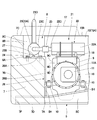
- FIG. 1 is a side view showing a hydraulic excavator applied to a first embodiment of the present invention. It is a top view of the upper turning body which shows the state which mounted the counterweight, the engine, the exhaust-gas aftertreatment apparatus, etc. on the turning frame. It is a top view which expands and shows the engine, PM collection filter apparatus, NOx purification apparatus, processing apparatus support bracket, etc. in FIG.
- FIG. 4 is a cross-sectional view of an engine, a PM collection filter device, a NOx purification device, and the like as seen from the direction of arrows IV-IV in FIG.
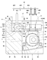
- FIG. 5 is a cross-sectional view similar to FIG.
- FIG. 4 illustrating a state in which the counterweight is removed from the turning frame and the NOx purification device is attached to the engine using the processing equipment support bracket.
- FIG. 4 is a plan view similar to FIG. 3 showing a state in which the counterweight is removed from the turning frame.
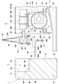
- FIG. 7 is a cross-sectional view of the PM collection filter device, the NOx purification device, and the processing equipment support bracket attached to the engine, as viewed from the direction of arrows VII-VII in FIG. It is sectional drawing similar to FIG. 4 which shows the processing equipment support bracket by 2nd Embodiment, NOx purification apparatus, etc. It is sectional drawing which shows the state which removed the counterweight from the turning frame, and attached the processing equipment support bracket and the NOx purification apparatus to the engine.
- FIG. 6 is a cross-sectional view similar to FIG. 5 showing a first modification in which the NOx purification device is attached to the turning frame via the processing equipment support bracket. It is a top view similar to FIG. 3 which shows the 2nd modification which attached PM collection filter apparatus to the counterweight.
- FIG. 1 to FIG. 7 show a first embodiment of the present invention.
- a PM collection filter device that collects and removes particulate matter (PM) in exhaust gas, a nitrogen oxide (NOx) in exhaust gas using an aqueous urea solution, a selective reduction catalyst, and the like.
- 1 illustrates a hydraulic excavator including an exhaust gas aftertreatment device configured by a NOx purification device for purification.
- reference numeral 1 denotes a hydraulic excavator as a typical example of a construction machine.
- the hydraulic excavator 1 includes a self-propelled crawler-type lower traveling body 2 and an upper portion mounted on the lower traveling body 2 so as to be able to turn.
- the revolving body 3 constitutes a vehicle body.
- a work device 4 is provided on the front side of the upper swing body 3 so as to be able to move up and down, and the work device 4 is used for excavating soil and the like.
- the upper swing body 3 includes a swing frame 5, a cab 6, an engine 9, an exhaust gas aftertreatment device 21, and the like which will be described later.
- Reference numeral 5 denotes a revolving frame serving as a base of the upper revolving structure 3, and the revolving frame 5 forms a strong support structure and is attached to the lower traveling body 2 so as to be revolved via a revolving device (not shown). ing.
- the revolving frame 5 has a thick bottom plate 5A extending in the front and rear directions, and a left standing on the bottom plate 5A and extending in the front and rear directions with a predetermined interval in the left and right directions.
- the left side frame 5F is fixed to the front end of the overhanging beam 5D and extends in the front and rear directions
- the right side frame 5G is fixed to the front end of each right overhanging beam 5E and extends in the front and rear directions.
- the foot portion of the working device 4 is attached to the front end portions of the left and right vertical plates 5B and 5C constituting the revolving frame 5 so as to be able to be lifted and lowered, and the rear ends of the vertical plates 5B and 5C are described later.
- a counterweight 7 is attached.
- each of the vertical plates 5B and 5C is provided with a plurality of engine support leg portions 5H that are positioned in front of the counterweight 7 and that face in the front and rear directions and are integrally fixed. Yes.
- Each engine support leg 5H supports an engine 9 described later.
- the cab 6 is mounted on the left front side of the revolving frame 5.
- the cab 6 defines an operator's cab, and a cab 6 is provided with a driver's seat on which the operator is seated, various operation levers (none of which are shown), and the like.
- the counterweight 7 indicates a counterweight attached to the rear end portion of the revolving frame 5, and the counterweight 7 balances the weight with the work device 4.
- the counterweight 7 is integrally formed by using, for example, casting means, and the counterweight 7 faces a later-described engine 9 and has a rectangular shape extending in the left and right directions.
- the front surface 7A is a vertical surface
- the rear surface 7B is curved in an arc shape and extends in the left and right directions
- the upper surface 7C and the lower surface 7D.
- a left frame mounting recess 7E and a right frame mounting recess 7F opened in the front surface 7A and the lower surface 7D are formed by notching the front surface 7A and the lower surface 7D toward the rear surface 7B. ing.
- the counterweight 7 becomes the rear end of the revolving frame 5 Removably attached to the part.
- the counterweight 7 is removed from the turning frame 5.
- the counterweight 7 is transported to the work site separately from the vehicle body of the hydraulic excavator 1 constituted by the lower traveling body 2 and the upper swing body 3, and is attached to the turning frame 5 again at the work site.
- the recessed portion 8 is a recessed portion provided on the upper surface 7C side of the counterweight 7, and the recessed portion 8 accommodates a NOx purification device 23 described later.
- the recessed portion 8 is a rectangular parallelepiped shape extending in the left and right directions surrounded by the bottom surface 8A, the rear surface 8B, the left side surface 8C and the right side surface 8D by cutting out the front surface 7A and the top surface 7C of the counterweight 7.
- the recessed portion 8 is open to the front surface 7A and the upper surface 7C of the counterweight 7.
- central female screw holes 8E for fixing a NOx purification device 23 to be described later are screwed in the left and right central portions of the bottom surface 8A.
- two left female screw holes 8F for fixing a processing equipment support bracket 26 described later are screwed.
- Two right female screw holes 8G for fixing a processing equipment support bracket 26 to be described later are screwed in the vicinity of the right corner where the bottom surface 8A and the right surface 8D intersect. Therefore, in the first embodiment, the left female screw hole 8 ⁇ / b> F and the right female screw hole 8 ⁇ / b> G in the recessed portion 8 constitute a support member storage unit for the counterweight 7.
- the 9 indicates an engine that is located on the front side of the counterweight 7 and is mounted on the rear side of the revolving frame 5.
- the engine 9 is constituted by, for example, a diesel engine.
- the engine 9 is elastically supported via an anti-vibration mount member 10 on an engine support leg 5H provided on the rear side of the revolving frame 5, and as a whole extends in the left and right directions. Has been placed.
- the engine 9 drives a hydraulic pump 11 which will be described later, and exhaust gas discharged from the engine 9 is introduced into an exhaust gas aftertreatment device 21 which will be described later through an exhaust pipe 9A which constitutes a part of the exhaust gas passage. It has a configuration.
- a cooling fan 9 ⁇ / b> B that is rotated by the engine 9 is provided on the left side of the engine 9.
- the engine 9 is provided with a bracket fixing surface 9C for fixing a processing equipment support bracket 26, which will be described later, located at a portion facing the counterweight 7, and the bracket fixing surface 9C includes upper and lower portions.
- Two female screw holes 9D are screwed to each other at intervals.
- the hydraulic pump 11 is attached to the right side of the engine 9.
- the hydraulic pump 11 is driven by the engine 9 to discharge pressure oil for operation toward various hydraulic actuators mounted on the hydraulic excavator 1.
- the hydraulic pump 11 has a flange portion 11A that is bolted to the engine 9, and a support base 18 described later is attached to the flange portion 11A. .
- the heat exchanger 12 is disposed so as to face the cooling fan 9B of the engine 9, and the heat exchanger 12 includes, for example, a radiator, an oil cooler, an intercooler, and the like.
- the heat exchanger 12 cools the engine coolant, hydraulic oil, and supercharged air by releasing the heat of the refrigerant into the cooling air generated by the cooling fan 9B when the engine 9 is operated.
- the hydraulic oil tank 13 is located on the front side of the hydraulic pump 11 and is mounted on the right side of the revolving frame 5.
- the hydraulic oil tank 13 stores hydraulic oil supplied to various hydraulic actuators mounted on the hydraulic excavator 1. is there.
- the fuel tank 14 is disposed in front of the hydraulic oil tank 13, and the fuel tank 14 stores fuel supplied to the engine 9.
- the building cover 15 indicates a building cover provided on the revolving frame 5 between the cab 6 and the counterweight 7.
- the building cover 15 horizontally extends between the left and right side plates 15A extending forward and rearward on the left and right side frames 5F and 5G of the revolving frame 5 and between the upper ends of the left and right side plates 15A. And an upper surface plate 15B extending in the direction.
- the rear side of the building cover 15 is closed by the counterweight 7.
- an engine room 16 is defined in the building cover 15 in front of the counterweight 7, and the engine 9, the hydraulic pump 11, the heat exchanger 12, which will be described later, in the engine room 16.
- the PM collection filter device 22 and the like are accommodated.
- An opening (not shown) that opens to the engine chamber 16 is formed in the upper surface plate 15B of the building cover 15, and the engine 9, the PM collection filter device 22 and the like can be inspected through the opening.
- the engine cover 17 is provided on the upper surface plate 15B of the building cover 15, and the engine cover 17 is formed in a quadrangular lid shape having an open lower end.
- the engine cover 17 is supported on the upper surface plate 15B of the building cover 15 via a hinge member.
- the engine cover 17 covers the opening provided in the upper surface plate 15 ⁇ / b> B of the building cover 15 and the recessed portion 8 provided in the counterweight 7 so as to be openable and closable.
- the support base 18 is located on the right side of the engine 9 and provided above the hydraulic pump 11, and the support base 18 is attached to the engine 9 together with the flange portion 11 ⁇ / b> A of the hydraulic pump 11.
- a PM collection filter device 22 described later is supported on the upper surface side of the support base 18.
- the exhaust gas aftertreatment device 21 denotes an exhaust gas aftertreatment device connected to the exhaust pipe 9A of the engine 9.
- the exhaust gas aftertreatment device 21 constitutes an exhaust gas passage together with the exhaust pipe 9A, and removes harmful substances in the exhaust gas discharged from the engine 9.
- the exhaust gas aftertreatment device 21 applied to the first embodiment is attached to a PM collection filter device 22 (described later) attached on the support base 18 and the recessed portion 8 of the counterweight 7.
- two processing devices, which will be described later, with a NOx purification device 23 are connected in series via a vibration absorption tube 25.
- This PM collection filter device 22 indicates a PM collection filter device which is one of the two processing devices constituting the exhaust gas aftertreatment device 21.
- This PM collection filter device 22 collects particulate matter in exhaust gas, and has a cylindrical case 22A and a filter main body (not shown) provided in the cylindrical case 22A. It is comprised by.
- the cylindrical case 22 ⁇ / b> A of the PM collection filter device 22 is mounted on the support base 18 with the axial center line extending in the front and rear directions, and is installed in the building cover 15 together with the engine 9 and the hydraulic pump 11. Contained.
- An inflow pipe 22B connected to the exhaust pipe 9A of the engine 9 is provided on the outer peripheral side of the front end portion of the cylindrical case 22A.
- an outflow pipe 22C that protrudes rearward toward the counterweight 7 is provided at the rear end of the cylindrical case 22A, and the outflow pipe 22C is connected to an inflow pipe 23C of a NOx purification device 23 described later. Yes.
- the PM collection filter device 22 collects particulate matter contained in the exhaust gas introduced into the cylindrical case 22A through the inflow pipe 22B by the filter body, and burns and removes the collected particulate matter. It is. Therefore, the exhaust gas discharged to the exhaust pipe 9A of the engine 9 is supplied to the NOx purification device 23 described later through the outflow pipe 22C in a state where the particulate matter is removed by the PM collection filter device 22. ing.
- the NOx purification device 23 denotes a NOx purification device which is the other of the two processing devices constituting the exhaust gas aftertreatment device 21.
- the NOx purification device 23 includes a cylindrical cylindrical case 23A and a selective reduction catalyst (not shown) provided in the cylindrical case 23A.
- a urea water injection valve (not shown) is provided in an inflow pipe 23C, which will be described later, connected to the cylindrical case 23A.
- the urea water injection valve is an exhaust gas introduced into the cylindrical case 23A through the inflow pipe 23C.
- the aqueous urea solution is sprayed toward As a result, the selective reduction catalyst selectively decomposes nitrogen oxides contained in the exhaust gas introduced into the cylindrical case 23A with ammonia generated from the urea aqueous solution, and decomposes it into nitrogen and water. is there.
- the cylindrical case 23A of the NOx purification device 23 is disposed in the recessed portion 8 of the counterweight 7 with the axial center line extending leftward and rightward.
- Two mounting legs 23B are provided on the lower surface side of the cylindrical case 23A, and the bolts 24 inserted through the mounting legs 23B are screwed into a central female screw hole 8E provided in the bottom surface 8A of the recessed recess 8. Match. Thereby, the NOx purification device 23 is fixed on the bottom surface 8 ⁇ / b> A of the recessed portion 8.
- An inflow pipe 23C bent in an L shape toward the PM collection filter device 22 is provided at the right end of the cylindrical case 23A.
- the inflow pipe 23C is connected to the PM collection filter device via the vibration absorption pipe 25.
- 22 is connected to an outflow pipe 22C provided in the cylindrical case 22A.
- the upper surface on the left end side of the cylindrical case 23A is provided with an outflow pipe 23D extending upward, and the exhaust gas purified in the NOx purification device 23 is discharged to the outside through the outflow pipe 23D.
- the vibration absorbing tube 25 is formed of a flexible bellows tube.
- the vibration absorbing pipe 25 is transmitted to the PM collection filter device 22 attached to the engine 9 via the support base 18 and vibration transmitted to the NOx purification device 23 attached to the recessed portion 8 of the counterweight 7.
- the outlet pipe 22C of the PM collection filter device 22 and the inlet pipe 23C of the NOx purification device 23 are connected while absorbing the difference.
- the PM collection filter device 22 attached to the engine 9 and the NOx purification device 23 attached to the recessed portion 8 of the counterweight 7 can be opened and closed by the engine cover 17. Covered with The outflow pipe 23 ⁇ / b> D of the NOx purification device 23 is configured to protrude above the engine cover 17 when the engine cover 17 is closed.
- the exhaust gas aftertreatment device 21 exemplified in the first embodiment is constituted by the PM collection filter device 22 and the NOx purification device 23 provided in the middle of the exhaust gas passage of the engine 9.
- the collection filter device 22 is attached to the engine 9 via the support base 18, and the NOx purification device 23 is attached to the recessed portion 8 of the counterweight 7.
- the PM collection filter device 22 removes particulate matter in the exhaust gas. Collect and remove.
- the NOx purification device 23 decomposes nitrogen oxides contained in the exhaust gas into nitrogen and water. After purifying, it is configured to discharge to the outside through the outflow pipe 23D.
- the exhaust gas aftertreatment device 21 functions properly in a state where the PM collection filter device 22 and the NOx purification device 23 are incorporated in the exhaust gas passage of the engine 9. For this reason, when the PM collection filter device 22 or the NOx purification device 23 is removed from the exhaust gas passage of the engine 9, for example, the engine 9 is not permitted to start or a warning sound is emitted to the exhaust gas aftertreatment device 21.
- a safety device is set up such as to emit.
- reference numeral 26 denotes two processing equipment support brackets as processing equipment support members used in the first embodiment. Each of these processing equipment support brackets 26 replaces the NOx purification device 23 attached to the recessed portion 8 of the counterweight 7 when the counterweight 7 is removed from the turning frame 5 with the engine 9 instead of the counterweight 7. Support on the side.
- each processing equipment support bracket 26 is formed of a thick plate body bent in an L shape, and is a short vehicle body side fixing portion 26 ⁇ / b> A that is fixed to a bracket fixing surface 9 ⁇ / b> C of the engine 9. It has a long weight side fixing portion 26B extending to the counterweight 7 side (rear). Two bolt insertion holes 26A1 corresponding to the female screw holes 9D of the engine 9 are formed in the vehicle body side fixing portion 26A. In the weight side fixing portion 26B, two female screw holes 26B1 corresponding to the mounting leg portions 23B of the NOx purification device 23 are screwed.
- the height position of the upper surface of the weight side fixing portion 26 ⁇ / b> B is set to a height position equal to the bottom surface 8 ⁇ / b> A of the recessed portion 8.
- the bolt 27 inserted into the bolt insertion hole 26A1 of the processing equipment support bracket 26 is screwed into the female screw hole 9D of the engine 9, and the vehicle body side fixing portion 26A of the processing equipment support bracket 26 is attached. It is attached to the bracket fixing surface 9C of the engine 9.
- the bolt 24 inserted into the mounting leg 23B of the NOx purification device 23 removed from the counterweight 7 is screwed into the female screw hole 26B1 of the processing equipment support bracket 26, and the weight side fixing part 26B of the processing equipment support bracket 26 is inserted.
- a NOx purification device 23 is attached to the.
- each processing equipment support bracket 26 can be held in the vicinity of the left and right side surfaces 8 ⁇ / b> C and 8 ⁇ / b> D of the recessed portion 8.
- the hydraulic excavator 1 has the above-described configuration. Next, its operation and assembly of the exhaust gas aftertreatment device 21 when the hydraulic excavator 1 is transported with the counterweight 7 removed. Is described.
- the hydraulic excavator 1 is self-propelled by the lower traveling body 2 in the work site, and performs excavation work and the like using the work device 4 while turning the upper revolving body 3.
- the exhaust gas discharged to the exhaust pipe 9A of the engine 9 is introduced into the PM collection filter device 22 through the inflow pipe 22B, and the particulate matter is removed in the PM collection filter device 22.
- the exhaust gas is introduced into the NOx purification device 23 through the outflow pipe 22C and the inflow pipe 23C, and the nitrogen oxide is decomposed into nitrogen and water in the NOx purification device 23.
- the exhaust gas discharged from the engine 9 is purified by the exhaust gas aftertreatment device 21 including the PM collection filter device 22 and the NOx purification device 23, and then externally through the outflow pipe 23D of the NOx purification device 23. To be discharged.
- the assembly state of the exhaust gas aftertreatment device 21 during the operation of the hydraulic excavator 1 will be described. That is, as shown in FIGS. 3 and 4, when the counterweight 7 is attached to the swing frame 5 of the excavator 1, the PM collection filter device 22 is attached to the engine 9 via the support base 18. .
- the NOx purification device 23 is attached to the recessed portion 8 of the counterweight 7 using a bolt 24.
- the exhaust pipe 9A of the engine 9 is connected to the inflow pipe 22B of the PM collection filter device 22, and the outflow pipe 22C of the PM collection filter device 22 is connected to the inflow pipe 23C of the NOx purification device 23 via the vibration absorption pipe 25. Has been.
- the processing equipment support bracket 26 is recessed by screwing the bolts 27 inserted into the bolt insertion holes 26A1 into the left and right female screw holes 8F and 8G provided in the recessed portion 8 of the counterweight 7.
- the part 8 is stored in the vicinity of the left and right side surfaces 8C and 8D. Thereby, the loss of each processing equipment support bracket 26 can be reliably prevented.
- the bolts 27 are removed from the counterweight 7, and the two processing equipment support brackets 26 stored in the counterweight 7 are removed.
- Bolts 27 are inserted into the bolt insertion holes 26A1 of the respective processing equipment support brackets 26, and the bolts 27 are screwed into the female screw holes 9D of the engine 9.
- the vehicle body side fixing portion 26 ⁇ / b> A of the processing equipment support bracket 26 can be attached to the bracket fixing surface 9 ⁇ / b> C of the engine 9.
- the height position of the upper surface of the weight side fixing portion 26 ⁇ / b> B of the processing equipment support bracket 26 coincides with the height position of the bottom surface 8 ⁇ / b> A of the recessed portion 8 of the counterweight 7.
- the NOx purification device 23 attached to the counterweight 7 is attached to the engine 9 using the processing equipment support bracket 26.
- the NOx purification device 23 can be incorporated into the exhaust gas passage of the engine 9 together with the PM collection filter device 22.
- the upper surface of the weight side fixing portion 26 ⁇ / b> B of the processing equipment support bracket 26 is set to a height position equal to the bottom surface 8 ⁇ / b> A of the recessed portion 8 of the counterweight 7. Therefore, the inflow pipe 23C of the NOx purification device 23 supported by the processing equipment support bracket 26 and the outflow pipe 22C of the PM collection filter device 22 can be reliably connected via the vibration absorption pipe 25. .
- the excavator 1 can be self-propelled to the loading platform of a transport vehicle such as a trailer. Therefore, the workability when loading the excavator 1 is improved. Can be increased.
- the hydraulic excavator 1 when the hydraulic excavator 1 is unloaded from the loading platform of the transport vehicle that has arrived at the work site, the hydraulic excavator 1 can be driven by operating the engine 9 and the workability can be improved.
- the NOx purification device 23 is lifted using a rope 28 and a crane 29. Thereafter, the NOx purification device 23 is removed from the weight side fixing portion 26B of each processing equipment support bracket 26, and each of these processing equipment support brackets 26 is further removed from the bracket fixing surface 9C of the engine 9.
- the counterweight 7 is placed on the rear ends of the left and right vertical plates 5B and 5C of the revolving frame 5.
- the counterweight 7 can be attached to the revolving frame 5 by fastening the left and right frame attachment recesses 7E and 7F of the counterweight 7 with bolts or the like.
- the mounting leg portion 23 ⁇ / b> B of the NOx purification device 23 is disposed on the bottom surface 8 ⁇ / b> A of the recessed portion 8 provided in the counterweight 7. Thereafter, as shown in FIGS.
- the bolt 24 inserted into the mounting leg portion 23 ⁇ / b> B is screwed into the central female screw hole 8 ⁇ / b> E of the recessed portion 8, whereby NOx purification is performed in the recessed portion 8 of the counterweight 7.
- a device 23 can be attached.
- the NOx purification device 23 when the counterweight 7 is removed from the turning frame 5, the NOx purification device 23 can be supported by the processing equipment support bracket 26 attached to the engine 9. For this reason, even when the counterweight 7 is removed from the turning frame 5, the NOx purification device 23 can be connected to the PM collection filter device 22, and the exhaust gas aftertreatment device 21 can always function properly. it can.
- the engine 9 can be reliably operated even when the counterweight 7 is removed from the turning frame 5. Therefore, the vehicle body of the hydraulic excavator 1 can be self-propelled to the platform of the transportation vehicle, and workability when the vehicle body of the hydraulic excavator 1 is loaded on the transportation vehicle can be improved.
- the operation of replacing the NOx purification device 23 attached to the counterweight 7 with each processing equipment support bracket 26 is performed between the outflow pipe 22C of the PM collection filter device 22 and the inflow pipe 23C of the NOx purification device 23. It can be performed in a state of being connected via the vibration absorbing tube 25.
- the operation of reattaching the NOx purification device 23 attached to each processing equipment support bracket 26 to the counterweight 7 also vibrates between the outflow pipe 22C of the PM collection filter device 22 and the inflow pipe 23C of the NOx purification device 23. It can be performed in a state of being connected via the absorption tube 25.
- FIG. 8 and FIG. 9 show a second embodiment of the present invention.
- the feature of this embodiment is that a spacer is detachably provided between the vehicle body side fixing portion of the processing equipment support bracket and the engine.
- the same components as those in the first embodiment described above are denoted by the same reference numerals, and the description thereof is omitted.
- reference numeral 31 denotes two processing equipment support brackets as processing equipment support members used in the second embodiment.
- Each processing equipment support bracket 31 attaches the NOx purification device 23 to the engine 9 when the counterweight 7 is removed from the revolving frame 5.
- the processing equipment support bracket 31 is made of a thick plate bent in an L shape, and has a vehicle body side fixing portion 31A and a weight side fixing portion 31B.
- Two bolt insertion holes 31A1 corresponding to the female screw holes 9D of the engine 9 are formed in the vehicle body side fixing portion 31A.
- In the weight side fixing portion 31B two bolt insertion holes 31B1 corresponding to the mounting leg portion 23B of the NOx purification device 23 are formed.
- each processing equipment support bracket 31 is disposed between the bottom surface 8 ⁇ / b> A of the recessed portion 8 provided in the counterweight 7 and the mounting leg portion 23 ⁇ / b> B of the NOx purification device 23.
- the bolt 24 is inserted into the mounting leg portion 23B of the NOx purification device 23 and the bolt insertion hole 31B1 of the processing equipment support bracket 31, and the bolt 24 is screwed into the central female screw hole 8E of the recessed portion 8. Is done.
- each processing equipment support bracket 31 is fixed (jointly fastened) to the recessed portion 8 of the counterweight 7 together with the NOx purification device 23.
- a constant gap 32 is formed between the bracket fixing surface 9C of the engine 9 and the vehicle body side fixing portion 31A of each processing equipment support bracket 31.
- the spacer 33 denotes a spacer, which is detachably attached between the vehicle body side fixing portion 31A of the processing equipment support bracket 31 and the bracket fixing surface 9C of the engine 9.
- the spacer 33 is formed as a rectangular parallelepiped block having a front and rear length dimension A equal to the gap 32 between the bracket fixing surface 9C of the engine 9 and the vehicle body side fixing portion 31A of the processing equipment support bracket 31.
- the spacer 33 is provided with two bolt insertion holes 33A corresponding to the bolt insertion holes 31A1 formed in the vehicle body side fixing portion 31A of the processing equipment support bracket 31.
- the NOx purification device 23 via the processing equipment support bracket 31 and the height position of the upper surface of the weight side fixing portion 31 ⁇ / b> B and the recessed portion 8 of the counterweight 7. Is set to a height position equal to the height position of the upper surface of the weight-side fixing portion 31B when attached.
- the spacer 33 is disposed in the gap 32 between the bracket fixing surface 9C of the engine 9 and the vehicle body side fixing portion 31A of the processing equipment support bracket 31.
- the bolt 27 is inserted into the bolt insertion hole 31 ⁇ / b> A ⁇ b> 1 of the processing equipment support bracket 31 and the bolt insertion hole 33 ⁇ / b> A of the spacer 33, and the bolt 27 is screwed into the female screw hole 9 ⁇ / b> D of the engine 9.
- the vehicle body side fixing portion 31 ⁇ / b> A of each processing equipment support bracket 31 can be attached to the bracket fixing surface 9 ⁇ / b> C of the engine 9 via the spacer 33.
- the NOx purification device 23 is attached to the engine 9 side, and the counterweight 7 can be removed.
- the hydraulic excavator according to the second embodiment has the processing equipment support bracket 31 and the spacer 33 as described above.
- the weight-side fixing portion 31 ⁇ / b> B of 31 is fastened together with the recessed portion 8 of the counterweight 7 together with the NOx purification device 23.
- the NOx purification device 23 is attached to the recessed portion 8 of the counterweight 7 with the clearance 32 secured between the bracket fixing surface 9C of the engine 9 and the vehicle body side fixing portion 31A of each processing equipment support bracket 31. be able to.
- the bolt 24 is inserted again into the mounting leg 23B of the NOx purification device 23 and the bolt insertion hole 31B1 of the weight side fixing portion 31B of the processing equipment support bracket 31. . Further, a nut 34 is screwed onto the tip end side of the bolt 24 protruding to the lower surface side of the weight side fixing portion 31B.
- the vehicle body side fixing portion 31A of the processing equipment support bracket 31 is attached to the bracket fixing surface 9C of the engine 9 via the spacer 33, and the NOx purification device 23 is attached to the weight side fixing portion 31B of each processing equipment support bracket 31.
- the processing equipment support bracket 31 can be fixed to the engine 9 with the NOx purification device 23 still attached on the weight side fixing portion 31B of the processing equipment support bracket 31.
- the vehicle body side fixing portion 31 ⁇ / b> A of the processing equipment support bracket 31 is attached to the engine 9 via the spacer 33.
- the side fixing portion 31 ⁇ / b> A can be attached to the engine 9 via the spacer 33. Therefore, when the counterweight 7 is removed from the turning frame 5, the weight of the NOx purification device 23 can be supported by each processing equipment support bracket 31.
- the work of lifting the NOx purification device 23 using a crane or the like can be made unnecessary, and workability when the counterweight 7 is attached to and removed from the turning frame 5 can be improved.
- FIGS. 10 to 13 show a third embodiment of the present invention.
- the processing equipment is provided with a first mounting leg portion that is attached to the counterweight and a second mounting leg portion that is disposed at a position different from the first mounting leg portion. It is in.
- the same components as those in the first embodiment described above are denoted by the same reference numerals, and the description thereof is omitted.
- reference numeral 41 denotes a NOx purification device according to the third embodiment. Similar to the NOx purification device 23 according to the first embodiment described above, the NOx purification device 41 includes a cylindrical tubular case 41A, a urea water injection valve provided in the tubular case 41A, and selective reduction. And a catalyst (both not shown). An inflow pipe 41B connected to the PM collection filter device 22 outflow pipe 22C through the vibration absorption pipe 25 is provided at the right end of the cylindrical case 41A. An outflow pipe 41C for discharging the exhaust gas purified in the NOx purification device 41 is provided upright on the upper surface on the left end side of the cylindrical case 41A.
- first mounting legs 41D are provided on the lower surface side of the cylindrical case 41A so as to be spaced apart in the left and right directions.
- Each first mounting leg portion 41D has a protruding portion 41D1 with a bolt insertion hole protruding in the front and rear directions.
- the bolt 24 inserted into each protrusion 41D1 of the first mounting leg portion 41D is screwed into the central female screw hole 8E of the recessed portion 8 of the counterweight 7, whereby the bottom surface 8A of the recessed portion 8 is obtained.
- a NOx purification device 41 is fixed on the top.
- two second mounting legs 41E are provided on the upper surface side of the cylindrical case 41A so as to be spaced apart in the left and right directions.
- Each second mounting leg portion 41E has a protruding portion 41E1 with a bolt insertion hole protruding in the front and rear directions.
- the second mounting leg portion 41 ⁇ / b> E is attached to a processing equipment support bracket 42 described later.
- the processing equipment support bracket 42 shows two processing equipment support brackets as processing equipment support members used in the third embodiment. Each of these processing equipment support brackets 42 attaches the NOx purification device 41 to the engine 9 when the counterweight 7 is removed from the revolving frame 5. As shown in FIG. 12, the processing equipment support bracket 42 includes an elongated flat plate-like support arm portion 42 ⁇ / b> A that extends between the engine 9 and the counterweight 7 and extends in the front and rear directions, and the support arm portion 42 ⁇ / b> A.
- the vehicle body side fixing portion 42B provided on the front side and two female screw holes 42C as weight side fixing portions provided on the rear side of the support arm portion 42A are configured.
- the vehicle body side fixing portion 42B of the processing equipment support bracket 42 is composed of a pair of frames bent in an inverted U shape.
- the upper end portion of the vehicle body side fixing portion 42B is fixed to the front end side of the support arm portion 42A, and the lower end portion of the vehicle body side fixing portion 42B is attached to the upper surface side of the engine 9 using a bolt 43. (See FIG. 12).
- the two female screw holes 42 ⁇ / b> C provided on the rear side of the processing equipment support bracket 42 are arranged at positions corresponding to the second mounting legs 41 ⁇ / b> E of the NOx purification device 41. Accordingly, the NOx purification device 41 is attached to the rear end side of the processing equipment support bracket 42 by screwing the bolt 44 inserted into the protruding portion 41E1 of the second attachment leg portion 41E into the female screw hole 42C. It has become.
- the hydraulic excavator according to the third embodiment includes the NOx purification device 41 and the processing equipment support bracket 42 as described above.
- the first mounting leg portion 41 ⁇ / b> D of the device 41 can be mounted on the bottom surface 8 ⁇ / b> A of the recessed portion 8 provided in the counterweight 7 using the bolt 24.
- the lower end portion of the vehicle body side fixing portion 42 ⁇ / b> B constituting the processing equipment support bracket 42 is fixed to the upper surface side of the engine 9 using the bolts 43 as shown in FIG. 12.
- the bolt 44 inserted through the second mounting leg portion 41E of the NOx purification device 41 is screwed into a female screw hole 42C screwed to the support arm portion 42A of the processing equipment support bracket 42.
- the second attachment leg 41E of the NOx purification device 41 can be attached to the engine 9 via the processing equipment support bracket 42.
- the bolt 24 is removed from the first mounting leg portion 41D of the NOx purification device 41, and the counterweight 7 is removed from the swivel frame 5 in a state where the NOx purification device 41 is separated from the recessed portion 8 of the counterweight 7. .
- the NOx purification device 41 can be supported on the engine 9 via the processing equipment support bracket 42.
- the second mounting leg portion 41 ⁇ / b> E of the NOx purification device 41 is connected to the engine via each processing device support bracket 42 in advance. 9 can be attached.
- the NOx purification device 41 can be removed from the counterweight 7 while the weight of the NOx purification device 41 is reliably supported by each processing equipment support bracket 42, so that the counterweight 7 is attached to the revolving frame 5.
- the workability when removing can be further improved.
- a bracket fixing surface 9C is provided in a portion of the engine 9 that faces the counterweight 7, and the vehicle body side fixing portion 26A of the processing equipment support bracket 26 is attached to the bracket fixing surface 9C.
- the case is illustrated.
- the present invention is not limited to this, and for example, a configuration using a processing equipment support bracket 26 ′ according to the first modification shown in FIG. 14 may be used. That is, the vehicle body side fixing portion 26A ′ of the processing equipment support bracket 26 ′ has a longer length than that of the first embodiment, and the vehicle body side fixing portion 26A ′ is used as an engine support for the turning frame 5. It is good also as a structure attached to the leg part 5H.
- the weight side fixing portion 26B ′ has the same shape as that of the first embodiment. The same applies to the second and third embodiments.
- an exhaust gas aftertreatment device 21 configured by connecting two processing devices of a PM collection filter device 22 and a NOx purification device 23 in series will be described as an example. ing.
- the present invention is not limited to this, and can also be applied to, for example, an exhaust gas aftertreatment device configured by any one of the PM collection filter device 22 and the NOx purification device 23.
- the present invention may be applied to an exhaust gas aftertreatment device configured by connecting three or more treatment devices such as a PM collection filter device 22, a NOx purification device 23, and other treatment devices such as an oxidation catalyst. it can.
- the PM collection filter device 22 can be attached to the engine 9, and the NOx purification device 23 and other processing equipment such as an oxidation catalyst can be attached to the counterweight 7.
- the exhaust gas aftertreatment device 21 is mounted on the hydraulic excavator 1 .
- the present invention is not limited to this, and any construction machine equipped with an engine can be used, for example, a wheel loader. Can be widely applied to other construction machines, such as hydraulic crane, dump truck.
Landscapes
- Engineering & Computer Science (AREA)
- Mining & Mineral Resources (AREA)
- Civil Engineering (AREA)
- General Engineering & Computer Science (AREA)
- Structural Engineering (AREA)
- Mechanical Engineering (AREA)
- Exhaust Gas After Treatment (AREA)
- Component Parts Of Construction Machinery (AREA)
- Cooling, Air Intake And Gas Exhaust, And Fuel Tank Arrangements In Propulsion Units (AREA)
Abstract
Description
2 下部走行体(車体)
3 上部旋回体(車体)
4 作業装置
7 カウンタウエイト
8F 左側雌ねじ穴(支持部材保管部)
8G 右側雌ねじ穴(支持部材保管部)
9 エンジン
9A 排気管
21 排気ガス後処理装置
22 PM捕集フィルタ装置(処理機器)
23,41 NOx浄化装置(処理機器)
26,31,42,26′ 処理機器支持ブラケット(処理機器支持部材)
26A,31A,42B,26A′ 車体側固定部
26B,31B,26B′ ウエイト側固定部
32 隙間
33 スペーサ
41D 第1の取付脚部
41E 第2の取付脚部
42A 支持腕部
42C 雌ねじ孔(ウエイト側固定部)
Claims (5)
- 自走可能な車体(3)と、該車体(3)の前部側に設けられた作業装置(4)と、該作業装置(4)との重量バランスをとるため前記車体(3)の後部側に着脱可能に設けられたカウンタウエイト(7)と、該カウンタウエイト(7)の前側に位置して前記車体(3)に搭載されたエンジン(9)と、該エンジン(9)の排気ガス通路の途中に設けられ排気ガスを浄化処理するため1個の処理機器を用いてまたは複数個の処理機器(22,23,41)を接続することにより構成された排気ガス後処理装置(21)とを備えてなる建設機械において、
前記排気ガス後処理装置(21)を構成する少なくとも1個の処理機器(23,41)は、前記カウンタウエイト(7)を前記車体(3)に取付けたときには当該カウンタウエイト(7)に固定する構成とし、
前記エンジン(9)と前記車体(3)とのうちの一方の部材には、前記車体(3)から前記カウンタウエイト(7)を取外したときに前記少なくとも1個の処理機器(23,41)を支持する処理機器支持部材(26,31,42,26′)を設ける構成としたことを特徴とする建設機械。 - 前記処理機器支持部材(26,31,42,26′)は、前記エンジン(9)と前記車体(3)とのうち一方の部材に固定される車体側固定部(26A,31A,42B,26A′)と、該車体側固定部(26A,31A,42B,26A′)から前記カウンタウエイト(7)に向けて延びるウエイト側固定部(26B,31B,42C,26B′)とを有し、
前記車体(3)から前記カウンタウエイト(7)を取外すときには、前記処理機器支持部材(26,31,42,26′)の車体側固定部(26A,31A,42B,26A′)を前記一方の部材に取付け、前記処理機器支持部材(26,31,42,26′)のウエイト側固定部(26B,31B,42C,26B′)に前記少なくとも1個の処理機器(23,41)を取付ける構成としてなる請求項1に記載の建設機械。 - 前記カウンタウエイト(7)には、前記車体(3)に前記カウンタウエイト(7)を取付けたときに、前記エンジン(9)と前記車体(3)とのうち一方の部材から取外した前記処理機器支持部材(26)を保管する支持部材保管部(8F,8G)を設ける構成としてなる請求項1に記載の建設機械。
- 前記エンジン(9)と前記車体(3)とのうち一方の部材と前記処理機器支持部材(31)の車体側固定部(31A)との間には、これら両者間に着脱可能に取付けられるスペーサ(33)を設け、
前記車体(3)から前記カウンタウエイト(7)を取外すときには、前記処理機器支持部材(31)の車体側固定部(31A)を前記スペーサ(33)を介して前記一方の部材に取付けると共に、前記処理機器支持部材(31)のウエイト側固定部(31B)に前記少なくとも1個の処理機器(23)を取付ける構成とし、
前記車体(3)に前記カウンタウエイト(7)を取付けるときには、前記スペーサ(33)を取外すことにより前記処理機器支持部材(31)の車体側固定部(31A)と前記一方の部材との間に隙間(32)を形成し、前記処理機器支持部材(31)のウエイト側固定部(31B)を前記少なくとも1個の処理機器(23)と一緒に前記カウンタウエイト(7)に取付ける構成としてなる請求項2に記載の建設機械。 - 前記少なくとも1個の処理機器(41)には、前記車体(3)に前記カウンタウエイト(7)を取付けたときに当該カウンタウエイト(7)に取付けられる第1の取付脚部(41D)と、該第1の取付脚部(41D)とは異なる位置に配置された第2の取付脚部(41E)とを設け、
前記処理機器支持部材(42)は、前記エンジン(9)と前記カウンタウエイト(7)との間に前,後方向に延びて配置される支持腕部(42A)と、該支持腕部(42A)の前側に設けられ前記エンジン(9)と前記車体(3)とのうち前記一方の部材(9)に固定される車体側固定部(42B)と、前記支持腕部(42A)の後側に設けられ前記少なくとも1個の処理機器(41)の前記第2の取付脚部(41E)に固定されるウエイト側固定部(42C)とを有し、
前記車体(3)から前記カウンタウエイト(7)を取外すときには、前記少なくとも1個の処理機器(41)の前記第1の取付脚部(41D)を前記カウンタウエイト(7)から取外し、前記第2の取付脚部(41E)を前記処理機器支持部材(42)のウエイト側固定部(42C)に取付ける構成としてなる請求項1に記載の建設機械。
Priority Applications (4)
| Application Number | Priority Date | Filing Date | Title |
|---|---|---|---|
| US13/997,321 US8979125B2 (en) | 2011-02-25 | 2012-01-06 | Construction machine |
| EP12749206.4A EP2679730A4 (en) | 2011-02-25 | 2012-01-06 | Construction machine |
| KR1020137022147A KR101885233B1 (ko) | 2011-02-25 | 2012-01-06 | 건설 기계 |
| CN201280009486.4A CN103380252B (zh) | 2011-02-25 | 2012-01-06 | 工程机械 |
Applications Claiming Priority (2)
| Application Number | Priority Date | Filing Date | Title |
|---|---|---|---|
| JP2011039765A JP5490739B2 (ja) | 2011-02-25 | 2011-02-25 | 建設機械 |
| JP2011-039765 | 2011-02-25 |
Publications (1)
| Publication Number | Publication Date |
|---|---|
| WO2012114783A1 true WO2012114783A1 (ja) | 2012-08-30 |
Family
ID=46720573
Family Applications (1)
| Application Number | Title | Priority Date | Filing Date |
|---|---|---|---|
| PCT/JP2012/050159 Ceased WO2012114783A1 (ja) | 2011-02-25 | 2012-01-06 | 建設機械 |
Country Status (6)
| Country | Link |
|---|---|
| US (1) | US8979125B2 (ja) |
| EP (1) | EP2679730A4 (ja) |
| JP (1) | JP5490739B2 (ja) |
| KR (1) | KR101885233B1 (ja) |
| CN (1) | CN103380252B (ja) |
| WO (1) | WO2012114783A1 (ja) |
Cited By (3)
| Publication number | Priority date | Publication date | Assignee | Title |
|---|---|---|---|---|
| CN105074154A (zh) * | 2013-03-28 | 2015-11-18 | 洋马株式会社 | 作业车辆的发动机装置 |
| CN105074153A (zh) * | 2013-04-08 | 2015-11-18 | 日立建机株式会社 | 工程机械 |
| JP2017071941A (ja) * | 2015-10-06 | 2017-04-13 | 日立建機株式会社 | 建設機械 |
Families Citing this family (48)
| Publication number | Priority date | Publication date | Assignee | Title |
|---|---|---|---|---|
| JP2012171596A (ja) * | 2011-02-24 | 2012-09-10 | Hitachi Constr Mach Co Ltd | 建設機械 |
| JP5490739B2 (ja) * | 2011-02-25 | 2014-05-14 | 日立建機株式会社 | 建設機械 |
| WO2013154218A1 (ko) * | 2012-04-13 | 2013-10-17 | 볼보 컨스트럭션 이큅먼트 에이비 | 하이브리드형 건설기계 |
| KR20150032540A (ko) * | 2012-07-02 | 2015-03-26 | 볼보 컨스트럭션 이큅먼트 에이비 | 소음기가 구비된 카운터웨이트가 장착되는 건설기계 |
| JP5181076B1 (ja) * | 2012-08-03 | 2013-04-10 | 株式会社小松製作所 | 油圧ショベル |
| JP5543563B2 (ja) * | 2012-10-16 | 2014-07-09 | 株式会社小松製作所 | 排気処理ユニット |
| JP5975859B2 (ja) | 2012-11-29 | 2016-08-23 | ヤンマー株式会社 | エンジン装置 |
| JP5449517B1 (ja) * | 2012-12-20 | 2014-03-19 | 株式会社小松製作所 | 作業車両 |
| JP6161057B2 (ja) * | 2013-02-08 | 2017-07-12 | 東京濾器株式会社 | 排気ガス浄化装置 |
| JP6343119B2 (ja) | 2013-03-15 | 2018-06-13 | ヤンマー株式会社 | コンバインのエンジン装置 |
| JP6066787B2 (ja) | 2013-03-15 | 2017-01-25 | ヤンマー株式会社 | コンバインのエンジン装置 |
| KR20200008060A (ko) * | 2013-03-28 | 2020-01-22 | 얀마 가부시키가이샤 | 엔진 장치 |
| KR20160023768A (ko) * | 2013-07-08 | 2016-03-03 | 볼보 컨스트럭션 이큅먼트 에이비 | 건설기계 |
| JP5676827B1 (ja) * | 2013-08-09 | 2015-02-25 | 株式会社小松製作所 | 支持機構、排気処理ユニット、ホイールローダ |
| JP6164645B2 (ja) * | 2013-09-18 | 2017-07-19 | キャタピラー エス エー アール エル | 作業機械におけるカウンタウエイト装置 |
| KR101630253B1 (ko) * | 2013-09-25 | 2016-06-14 | 가부시키가이샤 고마쓰 세이사쿠쇼 | 작업 차량 |
| EP2853704B1 (en) | 2013-09-30 | 2017-04-26 | Kubota Corporation | Diesel engine |
| KR102344825B1 (ko) | 2013-10-25 | 2021-12-28 | 얀마 파워 테크놀로지 가부시키가이샤 | 작업 차량의 엔진 장치 |
| KR20160075502A (ko) | 2013-10-28 | 2016-06-29 | 얀마 가부시키가이샤 | 작업 차량의 엔진 장치 |
| JP5989017B2 (ja) * | 2014-01-30 | 2016-09-07 | 日立建機株式会社 | 建設機械 |
| WO2015141788A1 (ja) | 2014-03-20 | 2015-09-24 | ヤンマー株式会社 | エンジン装置 |
| WO2015141518A1 (ja) | 2014-03-20 | 2015-09-24 | ヤンマー株式会社 | エンジン装置 |
| KR20160133409A (ko) | 2014-03-20 | 2016-11-22 | 얀마 가부시키가이샤 | 엔진 장치 |
| CN106030069B (zh) | 2014-03-20 | 2019-05-03 | 洋马株式会社 | 发动机装置 |
| WO2015059983A1 (ja) * | 2014-08-08 | 2015-04-30 | 株式会社小松製作所 | 油圧ショベル |
| IN2015DN05047A (ja) * | 2014-08-08 | 2015-07-31 | Komatsu Mfg Co Ltd | |
| CN104334808B (zh) * | 2014-08-08 | 2016-10-19 | 株式会社小松制作所 | 液压挖掘机 |
| JP6176670B2 (ja) * | 2014-10-22 | 2017-08-09 | キャタピラー エス エー アール エル | 作業機械 |
| JP6197805B2 (ja) * | 2015-02-04 | 2017-09-20 | 株式会社豊田自動織機 | 産業車両 |
| US9587377B2 (en) | 2015-02-06 | 2017-03-07 | Harnischfeger Technologies, Inc. | Raised counterweight for a mining machine |
| CN107249301B (zh) | 2015-03-04 | 2020-10-16 | 洋马动力科技有限公司 | 联合收割机 |
| KR101698288B1 (ko) * | 2015-05-21 | 2017-01-19 | 가부시키가이샤 고마쓰 세이사쿠쇼 | 유압 셔블 |
| JP6497737B2 (ja) * | 2015-06-18 | 2019-04-10 | キャタピラー エス エー アール エル | 建設機械におけるカウンタウエイト支持構造 |
| CN105035039A (zh) * | 2015-08-08 | 2015-11-11 | 黄浩 | 一种防污染农业机械 |
| JP6280536B2 (ja) * | 2015-12-11 | 2018-02-14 | ヤンマー株式会社 | トラクタ |
| KR20230054501A (ko) | 2015-12-11 | 2023-04-24 | 얀마 파워 테크놀로지 가부시키가이샤 | 콤바인 |
| JP6664964B2 (ja) * | 2016-01-05 | 2020-03-13 | 住友建機株式会社 | ショベル |
| CN109072753B (zh) | 2016-02-19 | 2021-01-29 | 洋马动力科技有限公司 | 发动机装置 |
| DE102016105888B4 (de) | 2016-03-31 | 2018-02-22 | Komatsu Ltd. | Abgasnachbehandlungsanordnung, Motoranordnung und Arbeitsfahrzeug |
| JP6881334B2 (ja) * | 2018-01-29 | 2021-06-02 | 株式会社豊田自動織機 | 排気ガス浄化装置 |
| US11518235B2 (en) | 2018-06-01 | 2022-12-06 | Manitowoc Crane Companies, Llc | Mounting arrangement for engine exhaust aftertreatment system on crane carrier |
| JP7045659B2 (ja) * | 2019-03-18 | 2022-04-01 | ヤンマーパワーテクノロジー株式会社 | 建設機械 |
| JP2020153336A (ja) * | 2019-03-22 | 2020-09-24 | ヤンマーパワーテクノロジー株式会社 | エンジン |
| JP7503975B2 (ja) * | 2020-09-04 | 2024-06-21 | 株式会社小松製作所 | 作業機械 |
| JP7557350B2 (ja) * | 2020-11-19 | 2024-09-27 | ヤンマーホールディングス株式会社 | ディーゼルエンジン |
| US20230011309A1 (en) * | 2021-07-08 | 2023-01-12 | Nuhn Industries Ltd. | Boom mounted pump |
| US20240018964A1 (en) * | 2021-07-08 | 2024-01-18 | Nuhn Industries Ltd. | Boom mounted pump |
| CN118911228B (zh) * | 2024-07-23 | 2026-04-14 | 中联重科土方机械有限公司 | 平台系统的尺寸补偿方法、平台系统和作业机械 |
Citations (3)
| Publication number | Priority date | Publication date | Assignee | Title |
|---|---|---|---|---|
| JP2003041627A (ja) * | 2001-07-31 | 2003-02-13 | Shin Caterpillar Mitsubishi Ltd | 建設機械のカウンタウエイト内蔵の排ガス低減装置 |
| JP2008231757A (ja) * | 2007-03-20 | 2008-10-02 | Komatsu Ltd | 建設車両 |
| JP2009184558A (ja) | 2008-02-07 | 2009-08-20 | Hitachi Constr Mach Co Ltd | 建設機械のNOx低減装置の配設構造 |
Family Cites Families (8)
| Publication number | Priority date | Publication date | Assignee | Title |
|---|---|---|---|---|
| JPH09112262A (ja) * | 1995-10-16 | 1997-04-28 | Sumitomo Constr Mach Co Ltd | 建設機械のマフラ取付装置 |
| JP2000265837A (ja) * | 1999-03-16 | 2000-09-26 | Kobelco Contstruction Machinery Ltd | 建設機械のエンジン排気装置 |
| JP2003112262A (ja) * | 2001-10-03 | 2003-04-15 | Hitachi Metals Ltd | 間隔保持部材および電極ホルダ並びにそれらを用いるプラズマトーチ |
| ITTO20020036A1 (it) * | 2002-01-11 | 2003-07-11 | Fiat Hitachi Excavators S P A | Macchina operatrice, in particolare per movimento terra. |
| JP4900163B2 (ja) * | 2007-09-26 | 2012-03-21 | コベルコ建機株式会社 | 建設機械 |
| JP4928474B2 (ja) * | 2008-01-08 | 2012-05-09 | 日立建機株式会社 | 建設機械のNOx低減装置の配設構造 |
| EP2287030A4 (en) * | 2008-05-22 | 2018-04-04 | Hitachi Construction Machinery Co., Ltd | Construction machine |
| JP5490739B2 (ja) * | 2011-02-25 | 2014-05-14 | 日立建機株式会社 | 建設機械 |
-
2011
- 2011-02-25 JP JP2011039765A patent/JP5490739B2/ja not_active Expired - Fee Related
-
2012
- 2012-01-06 EP EP12749206.4A patent/EP2679730A4/en not_active Withdrawn
- 2012-01-06 US US13/997,321 patent/US8979125B2/en not_active Expired - Fee Related
- 2012-01-06 CN CN201280009486.4A patent/CN103380252B/zh not_active Expired - Fee Related
- 2012-01-06 WO PCT/JP2012/050159 patent/WO2012114783A1/ja not_active Ceased
- 2012-01-06 KR KR1020137022147A patent/KR101885233B1/ko not_active Expired - Fee Related
Patent Citations (3)
| Publication number | Priority date | Publication date | Assignee | Title |
|---|---|---|---|---|
| JP2003041627A (ja) * | 2001-07-31 | 2003-02-13 | Shin Caterpillar Mitsubishi Ltd | 建設機械のカウンタウエイト内蔵の排ガス低減装置 |
| JP2008231757A (ja) * | 2007-03-20 | 2008-10-02 | Komatsu Ltd | 建設車両 |
| JP2009184558A (ja) | 2008-02-07 | 2009-08-20 | Hitachi Constr Mach Co Ltd | 建設機械のNOx低減装置の配設構造 |
Non-Patent Citations (1)
| Title |
|---|
| See also references of EP2679730A4 * |
Cited By (6)
| Publication number | Priority date | Publication date | Assignee | Title |
|---|---|---|---|---|
| CN105074154A (zh) * | 2013-03-28 | 2015-11-18 | 洋马株式会社 | 作业车辆的发动机装置 |
| EP2980381A4 (en) * | 2013-03-28 | 2016-12-07 | Yanmar Co Ltd | MOTOR DEVICE FOR WORK VEHICLES |
| US9534523B2 (en) | 2013-03-28 | 2017-01-03 | Yanmar Co., Ltd. | Engine device for work vehicle |
| CN105074153A (zh) * | 2013-04-08 | 2015-11-18 | 日立建机株式会社 | 工程机械 |
| CN105074153B (zh) * | 2013-04-08 | 2018-06-15 | 株式会社Kcm | 工程机械 |
| JP2017071941A (ja) * | 2015-10-06 | 2017-04-13 | 日立建機株式会社 | 建設機械 |
Also Published As
| Publication number | Publication date |
|---|---|
| KR101885233B1 (ko) | 2018-08-03 |
| US8979125B2 (en) | 2015-03-17 |
| EP2679730A1 (en) | 2014-01-01 |
| KR20140018250A (ko) | 2014-02-12 |
| CN103380252A (zh) | 2013-10-30 |
| US20130343853A1 (en) | 2013-12-26 |
| JP2012177233A (ja) | 2012-09-13 |
| EP2679730A4 (en) | 2018-04-04 |
| CN103380252B (zh) | 2015-08-19 |
| JP5490739B2 (ja) | 2014-05-14 |
Similar Documents
| Publication | Publication Date | Title |
|---|---|---|
| JP5490739B2 (ja) | 建設機械 | |
| JP4705130B2 (ja) | 建設機械 | |
| CN102016255B (zh) | 废气处理装置 | |
| US8418448B2 (en) | Exhaust gas treatment device for construction machine | |
| JP6297905B2 (ja) | 建設機械 | |
| JP6212826B2 (ja) | 建設機械 | |
| US20130319787A1 (en) | Construction machine | |
| US9657459B2 (en) | Construction machine | |
| JP5631803B2 (ja) | 建設機械 | |
| JP6307019B2 (ja) | 建設機械 | |
| JP2008254572A (ja) | 建設機械 | |
| JP5496149B2 (ja) | 建設機械 | |
| JP6632920B2 (ja) | 建設機械 | |
| JP2016223214A (ja) | 建設機械 | |
| JP2020019402A (ja) | 建設機械 | |
| JP2014202024A (ja) | 建設機械 | |
| JP6170848B2 (ja) | 建設機械 | |
| JP7271745B2 (ja) | 建設機械 | |
| JP7594407B2 (ja) | 建設機械 | |
| JP6632884B2 (ja) | 小旋回型ショベル | |
| JP2014122592A (ja) | 建設機械の浄化装置 | |
| JP6371691B2 (ja) | 建設機械 |
Legal Events
| Date | Code | Title | Description |
|---|---|---|---|
| 121 | Ep: the epo has been informed by wipo that ep was designated in this application |
Ref document number: 12749206 Country of ref document: EP Kind code of ref document: A1 |
|
| WWE | Wipo information: entry into national phase |
Ref document number: 13997321 Country of ref document: US |
|
| WWE | Wipo information: entry into national phase |
Ref document number: 2012749206 Country of ref document: EP |
|
| ENP | Entry into the national phase |
Ref document number: 20137022147 Country of ref document: KR Kind code of ref document: A |
|
| NENP | Non-entry into the national phase |
Ref country code: DE |