WO2012086171A1 - Cartouche - Google Patents
Cartouche Download PDFInfo
- Publication number
- WO2012086171A1 WO2012086171A1 PCT/JP2011/007077 JP2011007077W WO2012086171A1 WO 2012086171 A1 WO2012086171 A1 WO 2012086171A1 JP 2011007077 W JP2011007077 W JP 2011007077W WO 2012086171 A1 WO2012086171 A1 WO 2012086171A1
- Authority
- WO
- WIPO (PCT)
- Prior art keywords
- cartridge
- axis direction
- printing material
- axis
- insertion hole
- Prior art date
Links
Images


Classifications
-
- B—PERFORMING OPERATIONS; TRANSPORTING
- B41—PRINTING; LINING MACHINES; TYPEWRITERS; STAMPS
- B41J—TYPEWRITERS; SELECTIVE PRINTING MECHANISMS, i.e. MECHANISMS PRINTING OTHERWISE THAN FROM A FORME; CORRECTION OF TYPOGRAPHICAL ERRORS
- B41J2/00—Typewriters or selective printing mechanisms characterised by the printing or marking process for which they are designed
- B41J2/005—Typewriters or selective printing mechanisms characterised by the printing or marking process for which they are designed characterised by bringing liquid or particles selectively into contact with a printing material
- B41J2/01—Ink jet
- B41J2/17—Ink jet characterised by ink handling
- B41J2/175—Ink supply systems ; Circuit parts therefor
- B41J2/17503—Ink cartridges
- B41J2/1752—Mounting within the printer
- B41J2/17523—Ink connection
-
- B—PERFORMING OPERATIONS; TRANSPORTING
- B41—PRINTING; LINING MACHINES; TYPEWRITERS; STAMPS
- B41J—TYPEWRITERS; SELECTIVE PRINTING MECHANISMS, i.e. MECHANISMS PRINTING OTHERWISE THAN FROM A FORME; CORRECTION OF TYPOGRAPHICAL ERRORS
- B41J2/00—Typewriters or selective printing mechanisms characterised by the printing or marking process for which they are designed
- B41J2/005—Typewriters or selective printing mechanisms characterised by the printing or marking process for which they are designed characterised by bringing liquid or particles selectively into contact with a printing material
- B41J2/01—Ink jet
- B41J2/17—Ink jet characterised by ink handling
- B41J2/175—Ink supply systems ; Circuit parts therefor
- B41J2/17503—Ink cartridges
- B41J2/1752—Mounting within the printer
-
- B—PERFORMING OPERATIONS; TRANSPORTING
- B41—PRINTING; LINING MACHINES; TYPEWRITERS; STAMPS
- B41J—TYPEWRITERS; SELECTIVE PRINTING MECHANISMS, i.e. MECHANISMS PRINTING OTHERWISE THAN FROM A FORME; CORRECTION OF TYPOGRAPHICAL ERRORS
- B41J2/00—Typewriters or selective printing mechanisms characterised by the printing or marking process for which they are designed
- B41J2/005—Typewriters or selective printing mechanisms characterised by the printing or marking process for which they are designed characterised by bringing liquid or particles selectively into contact with a printing material
- B41J2/01—Ink jet
- B41J2/17—Ink jet characterised by ink handling
- B41J2/175—Ink supply systems ; Circuit parts therefor
- B41J2/17503—Ink cartridges
- B41J2/17526—Electrical contacts to the cartridge
-
- B—PERFORMING OPERATIONS; TRANSPORTING
- B41—PRINTING; LINING MACHINES; TYPEWRITERS; STAMPS
- B41J—TYPEWRITERS; SELECTIVE PRINTING MECHANISMS, i.e. MECHANISMS PRINTING OTHERWISE THAN FROM A FORME; CORRECTION OF TYPOGRAPHICAL ERRORS
- B41J2/00—Typewriters or selective printing mechanisms characterised by the printing or marking process for which they are designed
- B41J2/005—Typewriters or selective printing mechanisms characterised by the printing or marking process for which they are designed characterised by bringing liquid or particles selectively into contact with a printing material
- B41J2/01—Ink jet
- B41J2/17—Ink jet characterised by ink handling
- B41J2/175—Ink supply systems ; Circuit parts therefor
- B41J2/17503—Ink cartridges
- B41J2/17543—Cartridge presence detection or type identification
- B41J2/1755—Cartridge presence detection or type identification mechanically
-
- B—PERFORMING OPERATIONS; TRANSPORTING
- B41—PRINTING; LINING MACHINES; TYPEWRITERS; STAMPS
- B41J—TYPEWRITERS; SELECTIVE PRINTING MECHANISMS, i.e. MECHANISMS PRINTING OTHERWISE THAN FROM A FORME; CORRECTION OF TYPOGRAPHICAL ERRORS
- B41J2/00—Typewriters or selective printing mechanisms characterised by the printing or marking process for which they are designed
- B41J2/005—Typewriters or selective printing mechanisms characterised by the printing or marking process for which they are designed characterised by bringing liquid or particles selectively into contact with a printing material
- B41J2/01—Ink jet
- B41J2/17—Ink jet characterised by ink handling
- B41J2/175—Ink supply systems ; Circuit parts therefor
- B41J2/17503—Ink cartridges
- B41J2/17553—Outer structure
-
- B—PERFORMING OPERATIONS; TRANSPORTING
- B41—PRINTING; LINING MACHINES; TYPEWRITERS; STAMPS
- B41J—TYPEWRITERS; SELECTIVE PRINTING MECHANISMS, i.e. MECHANISMS PRINTING OTHERWISE THAN FROM A FORME; CORRECTION OF TYPOGRAPHICAL ERRORS
- B41J2/00—Typewriters or selective printing mechanisms characterised by the printing or marking process for which they are designed
- B41J2/005—Typewriters or selective printing mechanisms characterised by the printing or marking process for which they are designed characterised by bringing liquid or particles selectively into contact with a printing material
- B41J2/01—Ink jet
- B41J2/17—Ink jet characterised by ink handling
- B41J2/175—Ink supply systems ; Circuit parts therefor
- B41J2/17566—Ink level or ink residue control
Definitions
- the present invention relates to a cartridge that accommodates a printing material therein.
- a printer which is an example of a printing apparatus, performs printing by ejecting ink from a print head onto a recording object (for example, printing paper).
- a technique for supplying ink to a print head a technique using an ink cartridge (also simply referred to as “cartridge”) that contains ink therein is known.
- the print head is operated in a state where ink is not supplied from the cartridge to the print head, there may be a problem that the print head is damaged due to so-called idle driving. Therefore, a technique is known in which detection means for detecting a state in which the ink in the cartridge is exhausted or a state in which the ink is low is mounted on the cartridge or the printer (for example, Patent Documents 1 and 2). A state in which the ink is exhausted or a state in which the ink is low is called an ink end.
- Patent Document 1 detects an ink end using a piezoelectric detection means.
- a liquid detection unit is provided in a cartridge, and a change in the volume of a detection chamber is detected by a piezoelectric detection unit, thereby detecting an ink end.
- electric supply means (wiring, electrode terminals, etc.) for supplying power to the piezoelectric detection means and exchanging signals between the piezoelectric detection means and the printer are provided in the cartridge. Necessary. For this reason, the structure of the cartridge becomes complicated, which may increase the size of the cartridge and increase the manufacturing cost.
- Patent Document 2 detects an ink end by an optical detection mechanism. An ink end is detected by providing a structure whose position changes with a change in the volume of the sub tank, and detecting the displacement of the structure with an optical sensor. In the technique of Patent Document 2, if the positional relationship among the sub tank, the structure, and the optical sensor deviates from the designed accurate positional relationship, the ink end may not be detected.
- the present invention has been made in view of the above-described problems, and an object of the present invention is to provide a technique for suppressing an increase in size of a cartridge or a printing apparatus. It is another object of the present invention to provide a technique for accurately positioning a cartridge with respect to a cartridge mounting portion of a printing apparatus. It is another object of the present invention to provide a technique that can accurately detect the end of a printing material.
- the present invention has been made to solve at least a part of the above problems, and can be realized as the following forms or application examples.
- Three spatial axes orthogonal to each other are defined as an X-axis, a Y-axis, and a Z-axis, and directions along the X-axis, the Y-axis, and the Z-axis are defined as an X-axis direction, a Y-axis direction, and a Z-axis direction, respectively.
- the cartridge described in the application example 1 is not provided with a piezoelectric detection mechanism for detecting that the printing material in the cartridge is exhausted or remaining (referred to as “end detection”). As a result, it is not necessary to provide electric conduction means (wiring, electrode terminals, etc.) for power supply and signal transmission / reception between the detection mechanism and the printer inside the cartridge. it can. Therefore, the cartridge can be reduced in size. Further, the manufacturing cost of the cartridge can be reduced.
- the first insertion hole is provided at an intermediate position between the first side surface and the second side surface of the front surface. That is, the cartridge is positioned at an intermediate position in the longitudinal direction of the front surface.
- the position shift near one end can be suppressed, but the position shift near the other end cannot be suppressed. Also, the deviation becomes large.
- the cartridge of Application Example 1 since the positioning is performed at the middle position in the longitudinal direction of the front surface of the cartridge, the positional deviation between both end portions in the longitudinal direction can be equally suppressed. Therefore, the cartridge can be accurately and efficiently positioned with respect to the cartridge mounting portion.
- the “intermediate position” used for “an intermediate position between the first apparatus side wall part and the second apparatus side wall part” and “an intermediate position between the first side surface and the second side surface” It is not necessary to be completely in the middle, and it is sufficient that it is not biased to either one of the side surface or the side wall.
- the “intermediate position” includes a position shifted from the center position of the first side surface and the second side surface in the Z-axis direction.
- the “intermediate position” includes a position where the central axis of the first insertion hole is within 10% of the center position with respect to the distance between the first side surface and the second side surface in the Z-axis direction. .
- the “intermediate position” is a distance from the center position to the distance between the first side surface and the second side surface in the Z-axis direction so that the center axis of the first insertion hole is disposed more intermediately. It is preferable to include a position within a range of 5% or less.
- the cartridge according to Application Example 1 further comprising: A detection chamber which is provided in the middle of the printing material flow path and whose volume changes in accordance with a change in internal pressure; A cartridge comprising: a lever member that contacts the tip of the rod, and a lever member that moves the rod along the axial direction by being displaced according to a change in the volume of the detection chamber.
- the rod used for detecting the end of the printing material is inserted into the first insertion hole, so that the cartridge can be attached to the cartridge mounting portion at a position intermediate in the longitudinal direction of the front surface of the cartridge. Positioning is performed.
- the position shift of the cartridge with respect to the rod can be suppressed, and the end detection of the printing material can be accurately performed. Further, since the cartridge is positioned with respect to the cartridge mounting portion using the rod used for detecting the end of the printing material, it is not necessary to provide a separate positioning member, and the number of parts can be reduced, and the cartridge can be downsized. In addition, the printing apparatus to which the cartridge is mounted can be reduced in size.
- Application Example 3 The cartridge according to Application Example 1 or Application Example 2, A cartridge in which a rod cover disposed on an outer periphery of the rod is also inserted into the first insertion hole. According to the cartridge described in the application example 2, the rod can be prevented from coming into contact with the wall forming the first insertion hole, so that the rod can be smoothly moved in accordance with the change in the volume of the detection chamber. Thereby, the end detection of the printing material can be performed more accurately.
- the cartridge according to any one of Application Examples 1 to 3, is A protective container having an opening on the ⁇ Y-axis direction side, in which the printing material container is housed; A cap provided on the ⁇ Y-axis direction side and attached to the protective container so as to close the opening of the protective container; The cartridge, wherein the second insertion hole and the first insertion hole are provided in the cap.
- the case includes the protective container and the cap, and the cap is provided with the second insertion hole and the first insertion hole.
- the protective container side in which the printing material container is accommodated is heavier as a whole than the cap side.
- the entire cartridge is tilted so that the rear side is lower than the front side.
- the protective container for storing the printing material container and the cap are separate members, the protective container can be moved slightly with respect to the cap by the clearance between the cap and the protective container. It becomes possible to do. Therefore, even if the weight of the printing material container is large, only the portion of the protective container is tilted, and the cap can be kept in a correct posture without tilting. Thereby, in the mounting state, it is possible to reduce the possibility that the position of the second insertion hole provided in the cap or the position of the first insertion hole with respect to the cartridge mounting portion deviates from the designed correct position.
- the cartridge according to Application Example 4 further including: In the mounted state, comprising a cartridge side terminal group that comes into contact with a device side terminal group provided in the cartridge mounting portion,
- the cartridge side terminal group is a cartridge provided on the cap.
- the cartridge side terminal group in the mounted state, is provided on the cap that is less likely to be displaced from the correct position, thereby electrically connecting the cartridge side terminal group and the apparatus side terminal group. Can be achieved stably.
- the cap has a first side surface constituting a part of the first side surface of the case, and a second side surface constituting a part of the second side surface of the case,
- the first side surface of the cap is provided with a first convex portion that protrudes in the + Z-axis direction.
- the first convex portion is inserted into the cartridge mounting portion when the cartridge is inserted into the cartridge mounting portion and from the cartridge mounting portion.
- the second side surface of the cap is provided with a second convex portion projecting in the ⁇ Z-axis direction, and the second convex portion is used when the cartridge is inserted into the cartridge mounting portion and the cartridge is inserted into the cartridge mounting portion.
- the second device side wall portion extends in the Y-axis direction and is guided by a second rail having a different dimension in the X-axis direction from the first rail.
- the cartridge in which the dimension of the X-axis direction of the first convex portion and the second convex portion is different.
- the cartridge described in Application Example 6 since the first convex portion and the second convex portion having different dimensions in the X-axis direction are provided, the dimension in the X-axis direction of the first rail is made to correspond to the first convex portion, By making the size of the two rails in the X-axis direction correspond to the second convex portion, the cartridge is mounted in a wrong state in which the first side surface and the second side surface of the cartridge are reversed from the original positional relationship. Can be prevented.
- the protective container has a first side surface constituting another part of the first side surface of the case, and a second side surface constituting another part of the second side surface of the case, A first container-side convex portion protruding in the + Z-axis direction is provided on the first side surface of the protective container, and the first container-side convex portion is inserted when the cartridge is inserted into the cartridge mounting portion.
- the second side surface of the protective container is provided with a second container-side convex portion protruding in the ⁇ Z-axis direction, and the second container-side convex portion is used when the cartridge is inserted into the cartridge mounting portion.
- a portion on the + Y-axis direction side of at least one of the first container-side convex portion and the second container-side convex portion is compared with other portions located on the ⁇ Y-axis direction side with respect to the portion.
- at least one of the first container-side convex portion and the second container-side convex portion has a portion whose dimension in the X-axis direction is larger than other portions.
- Application Example 8 The cartridge according to any one of Application Examples 1 to 7, The cartridge has an opening end on the ⁇ Y axis direction side of the first insertion hole provided at a position where the rod is inserted before the printing material supply pipe is inserted into the printing material supply port. According to the cartridge described in Application Example 8, after the printing material cartridge is guided to the correct position in the cartridge mounting portion by the rod, the connection between the printing material supply pipe and the printing material supply port is performed. Therefore, it is possible to prevent the printing material supply pipe from being damaged when the leading end of the printing material supply pipe collides with a position different from the printing material supply port of the cartridge.
- Application Example 10 The cartridge according to Application Example 8 or Application Example 9, further comprising: A cartridge-side identification member for identifying the type of the cartridge depending on whether or not the device-side identification member provided in the cartridge mounting portion can be fitted; The cartridge side identification member is fitted with the apparatus side identification member after the rod is inserted into the first insertion hole and before the printing material supply pipe is inserted into the printing material supply port. A cartridge that is configured to initiate mating.
- the cartridge side identification member is the device side identification member. In this case, further insertion of the cartridge can be inhibited. Therefore, the possibility that an incorrect type of cartridge is connected to the printing material supply pipe can be reduced. Further, after the rod is inserted into the first insertion hole and the cartridge is positioned with respect to the cartridge mounting portion, the fitting of the apparatus side identification member and the cartridge side identification member is started. Thereby, the position shift of the cartridge side identification member with respect to the apparatus side identification member can be suppressed.
- the possibility that the cartridge-side identification member hits the apparatus-side identification member and the fitting is hindered can be reduced. Further, when an incorrect type of cartridge is to be mounted on the cartridge mounting portion, the cartridge-side identification member can reliably contact the apparatus-side identification member, and further insertion of the cartridge can be hindered. Therefore, the possibility that an incorrect type of cartridge is connected to the printing material supply pipe can be reduced.
- the printing material supply port, the opening end of the first insertion hole, and the end of the cartridge side identification member in the ⁇ Y-axis direction are in a predetermined positional relationship. After that, and before the printing material supply pipe is inserted into the printing material supply port, the engagement between the cartridge side identification member and the apparatus side identification member can be started.
- the cartridge-side identification member is formed of at least one or more ribs, and a pattern determined by the number and position of the ribs varies depending on the type of the cartridge. It is preferable.
- the cartridge side identification member can be formed with a simple configuration using ribs.
- the first insertion hole has a predetermined length in the Y-axis direction
- the cartridge has an area of an opening end on the ⁇ Y axis direction side of the first insertion hole smaller than an area of an opening end of the first insertion hole in the + Y axis direction.
- the opening end on the ⁇ Y axis direction side that first receives the rod is wider than the opening end on the + Y axis direction side that is the other opening end. It has become. Therefore, the cartridge can be positioned more accurately by inserting the rod to the opening end on the + Y-axis direction side while making the rod easy to be received in the first insertion hole.
- the cartridge according to Application Example 12 The cartridge according to Application Example 12,
- the first insertion hole is composed of one end side portion extending from the connection portion to the opening end on the ⁇ Y axis direction side, and the other end side portion extending from the connection portion to the opening end on the + Y axis direction side,
- the one end side portion is a truncated cone whose cross section parallel to the X axis and the Z axis is a circle
- the other end portion has a shape in which a cross section parallel to the X-axis and the Z-axis is formed by a combination of a pair of straight lines facing each other in the Z-axis direction and two arcs facing each other in the X-axis direction.
- a distance between the pair of straight lines constituting the cross section of the other end side portion is smaller than a diameter of the circle constituting the cross section of the one end side portion, and the distance of the other end side portion is
- a diameter of the pair of arcs constituting the cross section is the same as a diameter of the circle constituting the cross section of the one end side portion.
- the area of the cross section gradually decreases from the opening end on the ⁇ Y axis direction side toward the connection portion. Then, the shape of the cross section changes at the connection portion, that is, the entrance of the other end portion, and only the dimension in the Z-axis direction becomes small.
- the dimension in the X-axis direction does not change.
- the shape and area of the cross section do not change from the connecting portion to the opening end on the + Y axis direction side. Therefore, the rod can be smoothly guided from the one end side portion to the other end side portion.
- a gap is provided between the rod and the first insertion hole so that the rod can be smoothly guided to the opening end on the + Y-axis direction side, while in the Z-axis direction. makes it possible to stabilize the position of the rod and accurately position the cartridge with respect to the cartridge mounting portion.
- the present invention can be realized in various forms, and in addition to the configuration as a cartridge, the invention can be realized in aspects such as a cartridge manufacturing method, a printing apparatus, and a printing material supply system including the cartridge and the printing apparatus. Can do.
- FIG. 1 is a perspective view illustrating a configuration of a printing material supply system 1.
- FIG. FIG. 6 is a front view of a cartridge mounting portion 42.
- 4 is a side view of a cartridge mounting portion 42.
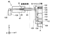
- FIG. It is a figure for demonstrating the detection method of an ink end.
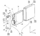
- 3 is an exploded perspective view of a cartridge 50.
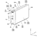
- FIG. 2 is an external perspective view of a cartridge 50.
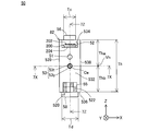
- FIG. 4 is a front view of the cartridge 50.
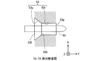
- FIG. FIG. 7B is a cross-sectional view taken along a plane including the central axis Ce of the first insertion hole 53, which is a part of the 7X-7X cross section of FIG. 7B is a part of a 7Z-7Z cross section of FIG.
- FIG. 7A which is a cross section obtained by cutting the cartridge 50 along a plane parallel to the Z axis and the Y axis and including the central axis Ce of the first insertion hole 53.
- FIG. It is the figure which showed the cross section parallel to the Z-axis and the X-axis of the one end side part 53y and the other end side part 53t in the connection part 53h.
- 4 is a schematic diagram for explaining an internal configuration of a cartridge 50.
- FIG. It is a 1st schematic diagram which shows a mode that a cartridge is mounted in a cartridge mounting part.
- It is the 2nd schematic diagram which shows a mode that a cartridge is mounted in a cartridge mounting part.
- FIG. 10 is a third schematic diagram illustrating how a cartridge is mounted in the cartridge mounting unit.
- FIG. 5 is an exploded perspective view showing a configuration of a printing material supply unit 74.
- FIG. FIG. 6 is a diagram illustrating a state in which ink is supplied to a cartridge mounting unit.
- FIG. 6 is a diagram illustrating a state in which ink is supplied to a cartridge mounting unit.
- FIG. 6 is an explanatory view showing a configuration of a lever member 120. It is the 1st figure for explaining detection of an ink end. It is a 2nd figure for demonstrating the detection of an ink end.
- FIG. 11 is a third diagram for explaining ink end detection. It is a figure for demonstrating the cartridge 50a of the 1st modification.
- FIG. 1 is a perspective view illustrating a configuration of a printing material supply system 1.
- XYZ axes orthogonal to each other are drawn.
- the XYZ axes are drawn as necessary in the subsequent drawings.
- the directions of the XYZ axes drawn in other drawings correspond to the XYZ axes in FIG.
- the printing material supply system 1 includes a printer 10 as a printing apparatus and a cartridge 50.
- the printer 10 of this embodiment is an ink jet printer that ejects ink from the head 22.
- the cartridge 50 contains ink as a printing material inside.
- the ink accommodated in the cartridge 50 flows through the tube 24 and is supplied to the head 22 of the carriage 20.
- the printer 10 mainly includes a cartridge mounting unit 42, a control unit 60, a carriage 20, a head 22, and a drive mechanism 30.
- the printer 10 includes an operation button 15 for the user to operate the operation of the printer 10.
- the cartridge 50 is detachably mounted on the cartridge mounting portion 42.
- four types of cartridges 50 corresponding to four colors (black, yellow, magenta, and cyan) of ink are installed one by one, that is, a total of four cartridges 50 are mounted on the cartridge mounting unit 42.
- a replacement cover 13 is provided on the front surface (the surface on the + Y axis direction side). When the + Z-axis side of the replacement cover 13 is tilted forward (+ Y-axis direction side), the opening of the cartridge mounting portion 42 appears, and the cartridge 50 can be attached and detached.
- ink can be supplied to the head 22 provided on the carriage 20 via the tube 24.
- ink is supplied to the head 22 by sucking ink in the cartridge 50 by a pump mechanism (not shown) of the printer 10.
- the tube 24 is provided for each type of ink.
- the head 22 is provided with a nozzle for each type of ink.
- the head 22 prints data such as characters and images by ejecting ink from the ejection nozzle toward the printing paper 2.
- the manner in which the cartridge 50 is mounted on the cartridge mounting portion 42 and the detailed configuration of the cartridge 50 and the cartridge mounting portion 42 will be described later.
- the printer 10 is a so-called “off-carriage type” printer in which the cartridge mounting portion 42 does not interlock with the movement of the carriage 20.
- the present invention can also be applied to a so-called “on-carriage type” printer in which a cartridge mounting portion 42 is provided in the carriage 20 and the cartridge mounting portion 42 moves together with the carriage 20.
- the control unit 60 controls each unit of the printer 10 and exchanges signals with the cartridge 50.
- the carriage 20 moves the head 22 relative to the printing paper 2.
- the drive mechanism 30 reciprocates the carriage 20 based on a control signal from the control unit 60.
- the drive mechanism 30 includes a timing belt 32 and a drive motor 34. By transmitting the power of the drive motor 34 to the carriage 20 via the timing belt 32, the carriage 20 reciprocates in the main scanning direction (X-axis direction).
- the printer 10 also includes a transport mechanism for moving the printing paper 2 in the sub-scanning direction (+ Y axis direction). When printing is performed, the printing paper 2 is moved in the sub-scanning direction by the transport mechanism, and the printing paper 2 after printing is output onto the front cover 11 from the opening 12.
- an area called a home position is provided at a position outside the printing area where the carriage 20 is moved in the main scanning direction, and a maintenance mechanism for performing maintenance so that printing can be performed normally is installed at the home position.
- the maintenance mechanism is pressed against the surface (nozzle surface) on which the nozzle is formed on the bottom surface side (side facing the printing paper 2) of the head 22, and forms a closed space so as to surround the ejection nozzle.
- An elevating mechanism (not shown) for raising and lowering the cap member 5 to press against the nozzle surface of the head 22 and a negative pressure is introduced into the closed space formed by pressing the cap member 5 against the nozzle surface of the ejection head 22
- a suction pump (not shown).
- the axis along the sub-scanning direction (front-rear direction) for transporting the printing paper 2 is the Y axis
- the axis along the gravity direction (vertical direction) is the Z axis.
- the axis along the moving direction (left-right direction) of the carriage 20 is defined as the X axis.
- the sub-scanning direction (front direction) is the + Y axis direction
- the opposite direction (rear direction) is the ⁇ Y axis direction
- the direction from the lower side to the upper side of the gravity direction (upward direction) is the + Z axis direction.
- the opposite direction (downward) is taken as the ⁇ Z axis direction.
- the printing material supply system 1 When the printing material supply system 1 is viewed from the front side (+ Y-axis direction side), the direction from the right side to the left side is the + X-axis direction, and the opposite direction is the ⁇ X-axis direction.
- the arrangement direction of the plurality of cartridges 50 is also the X-axis direction.
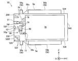
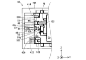
- FIG. 2 is a front view of the cartridge mounting portion 42.
- FIG. 3 is a side view of the cartridge mounting portion 42.
- FIG. 4 is a diagram for explaining an ink end detection method. In FIG. 4, a rod cover described later is not shown.
- a detailed configuration of the cartridge mounting portion 42 will be described with reference to FIGS.
- the X-axis direction is also called the width direction
- the Z-axis direction is also called the height direction
- the Y-axis direction is also called the length direction.
- the cartridge mounting portion 42 has a substantially rectangular parallelepiped shape.
- the cartridge mounting portion 42 is provided in a direction crossing the apparatus-side front wall 432, a first apparatus-side side wall 434 provided in a direction crossing the apparatus-side front wall 432, and the apparatus-side front wall 432. And a second device-side side wall portion 436 facing the first device-side side wall portion 434.
- the cartridge mounting portion 42 includes a device-side front wall portion 432, a first device-side sidewall portion 434, and a third device-side sidewall portion 438 provided in a direction intersecting with the second device-side sidewall portion 436, A fourth device-side side wall portion 439 provided in a direction crossing the device-side front wall portion 432, the first device-side side wall portion 434, and the second device-side side wall portion 436 and facing the third device-side side wall portion 438.
- Each wall portion 432, 434, 436, 438, 439 defines an accommodation space 450 for receiving the cartridge 50.
- the accommodation space 450 forms four mounting chambers 450a to 450d that receive the four types of cartridges 50, respectively.
- the cartridge mounting portion 42 has an opening 440 that faces the device-side front wall 432 with the accommodation space 450 interposed therebetween (FIG. 3).
- the cartridge 50 is attached to and detached from the cartridge mounting portion 42 by passing through the opening 440.
- the direction in which the cartridge 50 is inserted into the cartridge mounting portion 42 is the ⁇ Y axis direction, and the direction in which the cartridge 50 is removed from the cartridge mounting portion 42 is the + Y axis direction.
- intersection or “intersect” means a state where two elements intersect each other and actually intersect each other, a state where one element is extended, and a state where the other element intersects each other, This means that when the elements are extended, the elements intersect each other.
- the apparatus-side front wall 432 is located on the ⁇ Y axis direction side with respect to the accommodation space 450. In the case of the present embodiment, the apparatus-side front wall 432 is erected with respect to a horizontal plane (a plane parallel to the X axis and the Y axis).
- the first apparatus-side side wall 434 is located on the + Z axis direction side with respect to the accommodation space 450. In the case of the present embodiment, the first device side wall portion 434 is horizontal.
- the second device side wall 436 is positioned on the ⁇ Z axis direction side with respect to the accommodation space 450. In the case of the present embodiment, the second device side wall portion 436 is horizontal.
- the third device side wall 438 is located on the + X axis direction side with respect to the accommodation space 450. In the case of the present embodiment, the third device side wall portion 438 is erected with respect to the horizontal plane.
- the fourth device-side side wall 439 is located on the ⁇ X axis direction side with respect to the accommodation space 450. In the case of the present embodiment, the fourth device side wall portion 439 is erected with respect to the horizontal plane.
- the apparatus-side front wall 432 is provided with a printing material supply pipe 46 and a rod 45.
- the printing material supply pipe 46 and the rod 45 are arranged in the direction of the Z axis perpendicular to the Y axis.
- the printing material supply pipe 46 is provided on the + Z direction side of the rod 45.
- the rod 45 is provided on the ⁇ Z direction side of the printing material supply pipe 46. Therefore, the direction from the rod 45 toward the printing material supply pipe 46 in the Z-axis direction is the + Z-axis direction, and the opposite direction is the ⁇ Z-axis direction.
- the printing material supply pipe 46 and the rod 45 protrude from the apparatus-side front wall 432 by the same length.
- the tip 46c of the printing material supply pipe 46 and the tip 45c on the + Y-axis direction side of the rod 45 are arranged at the same position P in the Y-axis direction.
- the device-side front wall 432 is provided with a rod cover 47 that covers the outer periphery of the rod 45 and a spring 49.
- the rod 45, the rod cover 47, and the spring 49 are collectively referred to as a rod-shaped member 48.
- the printing material supply pipe 46 is connected to the cartridge 50 in a mounted state in which the cartridge 50 is mounted on the cartridge mounting portion 42. Thereby, the ink flows to the printer 10 side through the printing material supply pipe 46.
- the printing material supply pipe 46 has a base end portion 46 a that is fixed to the apparatus-side front wall portion 432 and a front end portion 46 b that is connected to the cartridge 50.
- the printing material supply pipe 46 has a central axis Ca extending along the Y-axis direction.
- the direction from the base end portion 46a toward the tip end portion 46b is the + Y-axis direction
- the opposite direction is the ⁇ Y-axis direction.
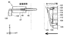
- the rod 45 is used for detecting the ink end of the cartridge 50.
- the rod 45 has an axis Cb extending in the Y-axis direction.
- the rod 45 is configured to be movable along the axis Cb direction (Y-axis direction). Then, by detecting the displacement of the rod 45 in the Y-axis direction with a sensor, the position in the Y-axis direction when the cartridge 50 has ink and the position in the Y-axis direction when the ink in the cartridge 50 runs out are changed.
- the ink end is detected by detecting the displacement.
- the ink end includes not only the case where ink is completely exhausted (state) but also the case where ink is remaining (state).
- the rod 45 is disposed through the device-side front wall 432.
- a portion disposed on the + Y-axis direction side from the device-side front wall portion 432 is a portion 45b on the + Y-axis direction side, and a portion disposed on the ⁇ Y-axis direction side from the device-side front wall portion 432. -This is called a portion 45a on the Y-axis direction side.
- the rod cover 47 is cylindrical and is disposed on the outer periphery of the rod 45.
- the spring 49 is provided between the spring receiving portion 45d provided on the portion 45b on the + Y-axis direction side of the rod 45 and the device-side front wall portion 432, and biases the rod 45 toward the + Y-axis direction.
- the spring 49 is disposed on the outer periphery of the rod 45.
- the spring 49 is covered with a rod cover 47.
- the description regarding the rod 45 after this can be replaced with the description of the rod-shaped member 48 as it is.
- the rod 45 is provided at an intermediate position between the first device-side side wall 434 and the second device-side side wall 436 in the device-side front wall 432.
- the Z-axis direction is provided at an intermediate position of a line segment connecting the inner surface of the first device-side side wall portion 434 and the inner surface of the second device-side side wall portion 436. That is, as shown in FIG. 2, the central axis Cb of the rod 45 is disposed at an intermediate position in the Z-axis direction between the first device-side side wall portion 434 and the second device-side side wall portion 436.
- the “intermediate position” does not have to be completely in the middle, and may be arranged so long as it is not biased to either one of the first and second device side wall portions 434 and 436.
- the “intermediate position” is within a range of 10% or less from the center position Vm with respect to the distance between the inner wall surfaces in the Z-axis direction of the first device-side sidewall portion 434 and the second device-side sidewall portion 436. Includes location.
- the “intermediate position” is the distance between the inner wall surfaces in the Z-axis direction of the first device-side side wall portion 434 and the second device-side side wall portion 436 so that the central axis Cb is arranged more in the middle.
- the detection mechanism 300 includes a rod 45, a light shielding unit 138, and a sensor 136.
- the sensor 136 is provided on the ⁇ Y axis direction side of the apparatus-side front wall portion 432.
- As the sensor 136 a so-called transmissive photosensor having a concave shape is used.
- the sensor 136 is provided with a light emitting portion and a light receiving portion (not shown) facing each other.
- the arrow of the broken line in a figure has shown the permeation
- the light shielding part 138 is provided at the tip of the rod 45 on the ⁇ Y axis direction side.
- the light shielding portion 138 is inserted between the light emitting portion and the light receiving portion of the sensor 136 to block light from the light emitting portion.
- the light receiving portion of the sensor 136 cannot receive the light from the light emitting portion, so that it can be detected that the position of the rod 45 has changed.
- the transmission type photosensor is used for the sensor 136 of a present Example, what is necessary is just to be able to detect the displacement of the rod 45, and it is not limited to a photosensor.
- the displacement of the rod 45 may be detected by turning on and off a mechanical switch with a detection piece having a shape like the light shielding portion 138.
- the displacement of the rod 45 may be detected by a detection mechanism other than the optical detection mechanism, for example, a mechanical detection mechanism or an electrical detection mechanism. The relationship between the detection of the displacement of the rod 45 and the ink end detection will be described later.
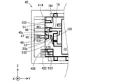
- the first apparatus-side side wall 434 includes a first rail 402 that extends from the + Y-axis direction side end to the ⁇ Y-axis direction side.
- the first rail 402 is a groove formed in the first device side wall portion 434.
- the second device side wall 436 includes a second rail 404 extending from the + Y axis direction end to the ⁇ Y axis direction side.
- the first rail 402 and the second rail 404 have different dimensions (widths) in the X-axis direction. In this embodiment, as shown in FIG. 2, the dimension Ta in the X-axis direction of the first rail 402 is smaller than the dimension Tb in the X-axis direction of the second rail.
- the cartridge mounting portion 42 further includes a contact mechanism 410, a device-side identification member 420, and a restriction member 406.
- the “device-side identification member 420” is also simply referred to as “identification member 420”.
- the contact mechanism 410 is provided at a corner portion where the first device side wall portion 434 and the device side front wall portion 432 intersect.
- the contact mechanism 410 includes a device-side terminal group 414 and a holding member 412 that holds the device-side terminal group 414.
- the device-side terminal group 414 has a plurality of terminals and is electrically connected to the control unit 60 (FIG. 1) of the printer 10.
- the identification member 420 is provided on the second device side wall portion 436.
- the identification member 420 is used to identify whether or not the correct type of cartridge 50 is mounted in each of the mounting chambers 450a to 450d of the accommodation space 450.
- the identification member 420 has a different shape depending on the color of ink stored in the cartridge 50 to be mounted.
- the identification member 420 is formed by at least one or more ribs 422, and the pattern determined by the number and position of the ribs 422 differs depending on the type of the cartridge 50 (ink color in this embodiment). In FIG. 2, the positions where the ribs 422 can be arranged are indicated by a lattice, and the positions where the ribs 422 are actually arranged are hatched.
- the cartridge side identification member formed by the rib provided on the cartridge 50 and the identification member 420 are fitted together. As a result, the correct type of cartridge 50 is mounted in the mounting chambers 450a to 450d. If the wrong type of cartridge 50 is inserted into each of the mounting chambers 450a to 450d, the ribs of the cartridge side identification member and the ribs 422 of the identification member 420 abut against each other, preventing the cartridge 50 from being mounted. This prevents the wrong type of cartridge 50 from being mounted in the mounting chambers 450a to 450d.
- the end 422c on the + Y-axis direction side of the identification member 420 is disposed at the same position P in the Y-axis direction as the tip 46c of the printing material supply pipe 46 and the tip 45c on the + Y-axis direction side of the rod 45.
- the regulating member 406 is in contact with the cartridge 50 and reduces the possibility that the cartridge 50 is excessively pushed into the accommodation space 450.
- the restriction member 406 is disposed on both sides of the identification member 420 in the X-axis direction.
- the restricting member 406 extends from the second device-side side wall 436 toward the first device-side side wall 434.
- FIG. 5 is an exploded perspective view of the cartridge 50.
- FIG. 6 is an external perspective view of the cartridge 50.
- FIG. 7A is a front view of the cartridge 50.
- 7B and 7C are partial cross-sectional views schematically showing a portion of the first insertion hole 53.
- FIG. 7B is a part of the 7X-7X cross section of FIG. 7A, and is a cross section of the cartridge 50 cut along a plane parallel to the X axis and the Y axis and including the central axis Ce of the first insertion hole 53.
- FIG. 7C is a part of the 7Z-7Z cross section of FIG.
- FIG. 7A is a cross section of the cartridge 50 cut along a plane parallel to the Z axis and the Y axis and including the central axis Ce of the first insertion hole 53.
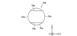
- FIG. 7D is a diagram illustrating a cross section of the one end side portion 53y and the other end side portion 53t of the connection portion 53h parallel to the Z axis and the X axis.
- FIG. 8 is a schematic diagram for explaining the internal configuration of the cartridge 50.
- FIG. 9A to FIG. 9C are schematic views showing how the cartridge is mounted in the cartridge mounting portion. 9A to 9C are time series in the order of FIGS. 9A, 9B, and 9C.
- the X-axis direction is also called the width direction
- the Y-axis direction is also called the length direction
- the Z-axis direction is also called the height direction.
- the cartridge 50 includes a printing material container 70, a cartridge case 72, and a printing material supply unit 74.
- the printing material storage unit 70 stores ink therein.
- the printing material container 70 is formed by laminating a film that does not allow liquid such as ink to pass through in a bag shape.
- a printing material supply unit 74 is attached to the printing material container 70.
- the printing material supply unit 74 is integrally provided with a printing material injection port 76, a printing material detection mechanism 80, a printing material outlet pipe 78, and a printing material flow path 90.
- the printing material injection port 76 is used for injecting ink into the printing material container 70 in the manufacturing stage of the cartridge 50, and the opening is closed after manufacturing.
- the printing material detection mechanism 80 is used for ink end detection using the detection mechanism 300. The detailed configuration of the printing material detection mechanism 80 will be described later.
- the printing material flow path 90 is a flow path for distributing the ink stored in the printing material storage unit 70 to the printer 10.
- the upstream end 77 of the printing material channel 90 opens in the printing material container 70, and the downstream end 78 f opens outward.
- the downstream end 78f is also referred to as a printing material supply port 78f.
- the printing material flow path 90 has a printing material supply port 78f at one end.
- a printing material container 70 is connected to the other end of the printing material channel 90.
- the printing material channel 90 is a channel that allows the printing material container 70 to communicate with the outside.
- the downstream end including the printing material supply port 78 f is formed by a cylindrical printing material outlet tube 78.
- the printing material supply port 78f is disposed in a second insertion hole 51 described later.
- the cartridge case 72 includes a protective container 84 and a cap 82.
- the protective container 84 houses most of the printing material container 70 inside.
- the protective container 84 is a substantially rectangular parallelepiped member having an opening on the ⁇ Y axis direction side.
- the cap 82 is attached to the protective container 84 so as to close the opening 75 of the protective container 84. Further, the cap 82 is not fixed to the protective container 84 so as not to move firmly.
- the cap 82 is configured to move slightly with respect to the protective container 84 by the clearance between the cap 82 and the protective container 84.
- the external appearance of the cartridge 50 is a substantially rectangular parallelepiped shape.
- the size of the cartridge 50 decreases in the order of the length direction (Y-axis direction), the height direction (Z-axis direction), and the width direction (X-axis direction).
- the cartridge 50 includes six surfaces 532, 534, 536, 538, 539, and 540 that form the outer surface.
- the cartridge 50 includes a front surface 532, a rear surface 540, a first side surface 534, a second side surface 536, a third side surface 538, and a fourth side surface 539.
- Each surface 532, 534, 536, 538, 539, 540 is substantially planar.
- the front surface 532 and parts of the side surfaces 534, 536, 538, and 539 on the ⁇ Y-axis direction side are constituted by a cap 82.
- a part of the rear surface 540 and the side surfaces 534, 536, 538, and 539 on the + Y-axis direction side is constituted by a protective container 84.
- the portions constituted by the cap 82 are referred to as first to fourth side surfaces of the cap 82, respectively.
- the portion constituted by the protective container 84 is referred to as the first to fourth side surfaces of the protective container 84, respectively.
- the surfaces 532, 534, 536, 538, 539, and 540 need not be perfect planes.
- the peripheral edge of the opening end of the first insertion hole 53 or the second insertion hole 51 provided in the front surface 532 may be slightly protruded from the front surface 532 so as to border the periphery of the hole.
- the front surface 532 and the rear surface 540 face each other in the Y-axis direction.
- the front surface 532 is located on the ⁇ Y axis direction side
- the rear surface 540 is located on the + Y axis direction side.
- the front surface 532 is located on the ⁇ Y axis direction side with respect to the printing material container 70.
- the front surface 532 faces the device-side front wall 432.
- the rear surface 540 is located on the + Y axis direction side with respect to the printing material accommodation unit 70.
- the rear surface 540 faces the front surface 532.
- the first side surface 534 is located on the + Z axis direction side with respect to the printing material accommodation unit 70.
- the first side surface 534 and the second side surface 540 intersect the front surface 532 and the rear surface 540.
- the first side surface 534 and the second side surface 540 face each other in the Z-axis direction.
- the first side surface 534 is located on the + Z axis direction side
- the second side surface 540 is located on the ⁇ Z axis direction side.
- the first side surface 534 is located on the + Z axis direction side with respect to the printing material accommodation unit 70.
- the second side surface 536 is located on the ⁇ Z-axis direction side with respect to the printing material container 70.
- the second side surface 536 faces the first side surface 534.
- the third side surface 538 and the fourth side surface 539 intersect the front surface 532, the rear surface 540, the first side surface 534, and the second side surface 540.
- the third side surface 538 and the fourth side surface 539 face each other in the X-axis direction.
- the third side surface 538 is located on the + X axis direction side
- the fourth side surface 539 is located on the ⁇ X axis direction side.
- the third side surface 538 is located on the + X axis direction side with respect to the printing material accommodation unit 70.
- the fourth side surface 539 is located on the ⁇ X axis direction side with respect to the printing material container 70.
- the fourth side surface 539 faces the third side surface 538.
- the front surface 532 formed by the cap 82 has a second insertion hole 51 into which the printing material supply pipe 46 is inserted and a first insertion hole 53 into which the rod 45 is inserted in the mounted state. Is formed.
- the second insertion hole 51 has a predetermined length in the Y-axis direction.
- the printing material supply pipe 46 (FIG. 3) is inserted into the second insertion hole 51.
- the printing material supply pipe 46 is connected to the printing material outlet pipe 78, and the ink in the printing material container 70 is supplied to the head 22 through the printing material supply pipe 46 and the tube 24.
- the state in which the printing material supply pipe 46 is connected to the printing material outlet pipe 78 means a state in which ink can flow from the printing material outlet pipe 78 to the printing material supply pipe 46.
- the first insertion hole 53 is provided at an intermediate position between the first side surface 534 and the second side surface 536 in the front surface 532. In other words, it is provided at an intermediate position connecting the first side surface 534 and the second side surface 536 in the Z-axis direction. That is, the central axis Ce of the first insertion hole 53 is disposed at an intermediate position in the Z-axis direction between the first side surface 534 and the second side surface 536.
- the “intermediate position” does not have to be completely in the middle, and may be arranged as long as it is not biased to either the first side surface 534 or the second side surface 536.
- the “intermediate position” includes a position where 0.4 ⁇ Th ⁇ Tha ⁇ ⁇ 0.6 ⁇ Th or 0.6 ⁇ Th ⁇ Thb ⁇ 0.4 ⁇ Th.
- the first insertion hole 53 does not appear to be biased to either the first side surface 534 or the second side surface 536 at a glance.
- the “intermediate position” is within 7.5% of the center position Vh with respect to the distance in the Z-axis direction between the first side surface 534 and the second side surface 536 so that the central axis Ce is arranged more in the middle. It is preferable that the position within the range is included.
- the first insertion hole 53 has a predetermined length in the Y-axis direction.
- the first insertion hole 53 has an opening end 53f on the ⁇ Y axis direction side and an opening end 53g on the + Y axis direction side.
- the first insertion hole 53 has an end portion 53y located on the ⁇ Y axis direction side and an other end portion 53t located on the + Y axis direction side with respect to the one end portion 53y. With the connection portion 53h as a boundary, the one end side portion 53y is located on the ⁇ Y axis direction side, and the other end side portion 53t is located on the + Y axis direction side.
- the one end side portion 53y includes an opening end 53f on the ⁇ Y axis direction side.
- the other end portion 53t includes an opening end 53g on the + Y axis direction side. That is, the part from the connection part 53h to the opening end 53f on the ⁇ Y axis direction side is the one end part 53y, and the part from the connection part 53h to the opening end 53g on the + Y axis direction side is the other end part 53g.
- the one end side portion 53y has a circular cross-sectional shape parallel to the X axis and the Z axis. The diameter of this circle decreases from the opening end 53f toward the + Y-axis direction. Further, as shown in FIG.
- the cross section parallel to the X axis and the Y axis and the cross section parallel to the Z axis and the Y axis of the one end side portion 53y are the sides on the ⁇ Y axis direction side formed by the opening end 53f. Is a trapezoid having a long side and a short side on the + Y-axis direction side formed by the connecting portion 53h. That is, the one end side portion 53y is a truncated cone. The other end side portion 53t is not a circle in cross section parallel to the X axis and the Z axis. As shown in FIGS.
- the cross section of the other end side portion 53t parallel to the X axis and the Z axis is a pair of straight lines 53p and 53p that face each other in the Z axis direction, and two that face each other in the X axis direction.
- the shape is formed by a combination with the arcs 53q and 53q.
- the shape of this cross section is the same from the connecting portion 53h to the opening end 53g on the + Y-axis direction side. That is, the other end side portion 53t is columnar. As shown in FIGS.
- the cross section of the other end side portion 53y parallel to the X axis and the Y axis and the cross section parallel to the Z axis and the Y axis are both rectangular.
- the area of the rectangle having a cross section parallel to the X axis and the Y axis shown in FIG. 7B is smaller than the area of the rectangle having a cross section parallel to the Z axis and the Y axis shown in FIG. 7C.
- the area of the opening end 53g in the + Y axis direction is smaller than the area of the opening end 53f in the ⁇ Y axis direction.
- this cross section is a circle in the one end side portion 53y.
- the area of this circle gradually decreases from the opening end 53f on the ⁇ Y axis direction side toward the connection portion 53h.
- the shape of the cross section changes to a shape formed by a combination of a pair of straight lines 53p, 53p and a pair of arcs 53q, 53q at the connection portion 53h, that is, the entrance of the other end portion 53t.
- the distance between the pair of straight lines 53p, 53p is smaller than the diameter of the circle constituting the cross section of the one end side portion 53y, and therefore the dimension in the Z-axis direction becomes small.
- the diameter of the pair of arcs 53q, 53q is the same as the diameter of the circle constituting the cross section of the one end side portion 53y, and therefore the dimension in the X-axis direction does not change.
- the shape and area of the cross section do not change from the connecting portion 53h to the opening end 53g on the + Y axis direction side.
- the rod 45 is inserted into the first insertion hole 53 from the ⁇ Y axis direction side toward the + Y axis direction.
- the opening end 53f on the ⁇ Y-axis direction side serving as the entrance is wide, the rod 45 can be easily received.
- the opening end 53g on the + Y axis direction side is narrow, the cartridge 50 can be accurately positioned by inserting the rod 45 up to the opening end 53g in the + Y axis direction.
- the cross-sectional area gradually decreases from the opening end 53f on the ⁇ Y axis direction side toward the connection portion 53h. Then, the shape of the cross section changes at the connection portion 53h, that is, the inlet of the other end side portion 53t, and only the dimension in the Z-axis direction becomes small.
- the dimension in the X-axis direction is the same as that of the one end side portion 53y. From the connecting portion 53h to the opening end 53g on the + Y axis direction side, the shape and area of the cross section do not change. Therefore, the rod 45 can be smoothly guided from the one end side portion 53y to the other end side portion 53t. In the other end portion 53t, in the X-axis direction, a gap is provided between the rod 45 and the first insertion hole 53 so that the rod can be smoothly guided to the opening end 53g on the + Y-axis direction side. In the Z-axis direction, the position of the rod 45 is stabilized, and the cartridge can be accurately positioned with respect to the cartridge mounting portion.
- the cartridge 50 further includes a cartridge-side identification member 520 (also simply referred to as “identification member 520”) in the cap 82.
- the identification member 520 is disposed at the concave corner portion 55 where the front surface 532 and the second side surface 536 intersect. Similar to the apparatus-side identification member 420, the identification member 520 is formed by at least one or more ribs 522. Further, the identification member 520 forms a different pattern depending on the ink color stored in the cartridge 50. Specifically, as shown in FIG. 7A, the concave portion provided in the corner portion 55 is divided into eight areas (in FIG. 7A, this area is shown in a lattice shape), and some of them are The rib 522 is arrange
- the area where the rib 522 is disposed varies depending on the ink color.
- FIG. 7A as an example of the rib arrangement pattern, the positions where the ribs 522 are arranged are hatched. 5 and 6, the identification member 520 is not shown.
- the end on the ⁇ Y-axis direction side of the cartridge-side identification member 520 is also referred to as “tip surface 520f”.
- the portion of the rod 45 disposed on the ⁇ Y axis direction side of the device-side front wall portion 432 (the portion 45a on the ⁇ Y axis direction side in FIG. 3) is omitted.
- the cartridge 50 is configured such that the rod 45 is inserted into the first insertion hole 53 before the printing material supply pipe 46 is inserted into the printing material supply port 78f. ing.
- the opening end 53f of the first insertion hole 53 is provided on the ⁇ Y axis direction side of the printing material supply port 78f.
- the rod 45 is first inserted into the first insertion hole 53.
- the cartridge 50 is mounted in the cartridge mounting portion 42, after the rod 45 is inserted into the first insertion hole 53 and before the printing material supply pipe 46 is inserted into the printing material supply port 78f.
- the cartridge 50 is configured so that the engagement between the cartridge side identification member 520 and the apparatus side identification member 420 is started.
- the front end surface 520f is provided on the + Y-axis direction side of the opening end 53f on the ⁇ Y-axis direction side of the first insertion hole 53, and the printing material supply port It is provided on the ⁇ Y axis direction side relative to 78f.
- 9A the rod 45 is first inserted into the first insertion hole 53.
- FIG. 9A the rod 45 is first inserted into the first insertion hole 53.
- the cartridge 50 comes into contact with the regulating member 406 (FIG. 2), and the cartridge 50 further moves in the ⁇ Y axis direction side. To prevent.
- the restricting member 406 contacts the surface (front surface 532) of the cartridge 50 that faces the ⁇ Y-axis direction (FIG. 9C).
- the cartridge 50 further includes a circuit board 200 on the cap 82.
- the circuit board 200 is disposed at the corner portion 52 where the front surface 532 and the first side surface 534 intersect.
- the circuit board 200 includes a cartridge-side terminal group 202 having a plurality of terminals provided on the front surface, and a storage device 204 provided on the back surface.
- the storage device 204 stores information about the cartridge 50 (for example, ink color).
- each terminal of the cartridge side terminal group 202 comes into contact with a corresponding terminal of the apparatus side terminal group 414.
- signals are exchanged between the circuit board 200 and the control unit 60 (FIG. 1).
- the first side surface 534 includes a first side surface 534a of the cap and a first side surface 534b of the protective container.
- a first cartridge projection 56 is provided on the first side surface 534.
- the first cartridge protrusion 56 protrudes from the first side surface 534 in the + Z-axis direction. Further, the first cartridge convex portion 56 extends in the Y-axis direction.
- the first cartridge convex portion 56 includes a first convex portion 56 a provided on the first side surface 534 a of the cap 82 and a first container side convex portion 56 b provided on the first side surface 534 b of the protective container 84. Is done.
- the first protrusion 56a protrudes from the first side surface 534a of the cap 82 in the + Z direction.
- the first container side convex portion 56 b protrudes from the first side surface 534 b of the protective container 84 in the + Z-axis direction. Further, the first container-side convex portion 56b extends in the Y-axis direction.
- the first cartridge convex portion 56 (56a, 56b) is provided when the cartridge 50 is inserted into the cartridge mounting portion 42 (see FIGS. 2 and 3) and when the cartridge 50 is removed from the cartridge mounting portion 42. Guided by rails 402 (see FIGS. 2 and 3).
- the second side surface 536 includes a second side surface 536a of the cap and a second side surface 536b of the protective container.
- a second cartridge convex portion 58 is provided on the second side surface 536.
- the second cartridge protrusion 58 protrudes from the second side surface 536 in the ⁇ Z axis direction. Further, the second cartridge convex portion 58 extends in the Y-axis direction.
- the second cartridge convex portion 58 includes a second convex portion 58 a provided on the second side surface 536 a of the cap 82 and a second container side convex portion 58 b provided on the second side surface 536 b of the protective container 84. Is done.
- the second convex portion 58a protrudes from the second side surface 536a of the cap 82 in the ⁇ Z direction.
- the second container side convex portion 58 b protrudes from the second side surface 538 b of the protective container 84 in the ⁇ Z axis direction.
- the first container-side convex portion 56b extends in the Y-axis direction.
- the second cartridge convex portion 58 (58a, 58b) is provided when the cartridge 50 is inserted into the cartridge mounting portion 42 (see FIGS. 2 and 3) and when the cartridge 50 is removed from the cartridge mounting portion 42. Guided by rails 404 (see FIGS. 2 and 3).
- the dimension Tc in the X-axis direction of the first cartridge protrusion 56 (56a, 56b) and the dimension Td in the X-axis direction of the second cartridge protrusion 58 (58a, 58b) are different.
- the dimension Td in the Z-axis direction of the second cartridge convex portion 58 (58a, 58b) is larger than the dimension Tc in the X-axis direction of the first cartridge convex portion 56 (56a, 56b).
- the dimension Tb in the X-axis direction of the second rail 404 of the cartridge mounting portion 42 for guiding the second cartridge convex portion 58 (58a, 58b) is the first cartridge.
- the dimension Ta in the Z-axis direction of the first rail 410 corresponds to the dimension Tc in the X-axis direction of the first cartridge convex portion 56 (56a, 56b), and the dimension in the X-axis direction of the second rail 404.
- Tb corresponds to the dimension Td in the X-axis direction of the second cartridge convex portion 58 (58a, 58b).
- the dimension Td in the X-axis direction of the second cartridge convex portion 58 (58a, 58b) is smaller than the dimension Tb in the X-axis direction of the second rail 404 and is smaller than the dimension Ta (56a, 56b) of the first rail 402. large.
- the dimension Tc in the X-axis direction of the first cartridge convex portion 56 (56a, 56b) is smaller than the dimension Ta in the X-axis direction of the first rail 402. That is, the relationship is Tc ⁇ Ta ⁇ Td ⁇ Tb.
- the second cartridge convex portion 58 specifically, the second convex portion 58a provided on the second side surface 536a of the cap 82 is provided. Since the cartridge 50 cannot be inserted into the first rail 402, it is possible to prevent the cartridge 50 from being mounted on the cartridge mounting portion 42.
- the first convex portion 56a and the first container-side convex portion 56b are arranged with a space portion 56c in the Y-axis direction.
- the 2nd convex part 58a and the 2nd container side convex part 58b provide the space part 58c in the Y-axis direction, and are arrange
- a leaf spring Sp provided in the cartridge mounting portion 42 enters the spaces 56c and 58c, and the cartridge 50 is urged toward the apparatus-side front wall 432 by the leaf spring Sp. Is done.
- the first cartridge convex portion 56 specifically, the first container-side convex portion 56b is shaped to continuously extend in the Y-axis direction.
- the second cartridge convex portion 58 specifically, the second container-side convex portion 58b is shaped so as to continuously extend in the Y-axis direction.
- the first convex portion 56a and the second convex portion provided at the front end portion in the ⁇ Y-axis direction Even 58a alone is possible.
- a certain amount of space in the Y-axis direction is provided at least at two locations on the first side surface 534 and at least two locations on the second side surface 536. It is only necessary that the protrusions are provided, and it is not essential that the protrusions extend in the Y-axis direction.
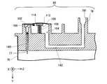
- FIG. 10 is an exploded perspective view showing the configuration of the printing material supply unit 74.
- the printing material detection mechanism 80 includes a detection chamber 100 having a substantially cylindrical shape.
- the detection chamber 100 is provided in the middle of the printing material flow path 90 (FIG. 8).
- an inflow port 102 into which ink in the printing material container 70 flows and an outflow port 104 through which ink flows out toward the printing material supply port 78f are opened.
- the detection chamber 100 is covered at its upper end surface with a film 118 formed of a flexible material.
- the volume of the detection chamber 100 changes as the film 118 is deformed in accordance with a change in internal pressure.
- the printing material detection mechanism 80 is further provided with a check valve 106 and a spring 108.
- the check valve 106 and the spring 108 are disposed in the detection chamber 100.
- the check valve 106 prevents the ink flowing from the inlet 102 into the detection chamber 100 from flowing backward.
- the spring 108 biases the film 118 toward the outside of the detection chamber 100.
- the spring 108 is disposed in the detection chamber 100 in a compressed state.
- the spring 108 is positioned by being fitted to a protrusion 110 erected upward from the bottom surface of the detection chamber 100.
- a pressure receiving plate 112 is inserted between the spring 108 and the film 118.
- the pressure receiving plate 112 is integrally formed by connecting a pressure receiving portion 114 that transmits the urging force of the spring 108 to the film 118 and a restriction portion 116 that restricts the movement of the check valve 106.
- a pressure receiving portion 114 that transmits the urging force of the spring 108 to the film 118
- a restriction portion 116 that restricts the movement of the check valve 106.
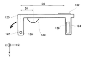
- the printing material detection mechanism 80 further includes a lever member 120.
- the lever member 120 is in contact with the film 118 constituting the one end surface (the upper end surface in the drawing) of the detection chamber 100 from the outside of the detection chamber 100.
- the lever member 120 is provided with a shaft hole 122 on one end side.
- the shaft hole 122 is fitted to the shaft pin 126 provided on the outer surface of the detection chamber 100, the lever member 120 is pivotally supported by the shaft pin 126 so as to be rotatable.
- a guide hole 124 is provided on the other end side of the lever member 120, and a guide pin 128 fixed to the printing material supply unit 74 is inserted into the guide hole 124 to rotate the lever member 120. Is to guide you.
- the contact portion with which the tip 45c of the rod 45 on the cartridge mounting portion 42 side contacts the upper surface of the lever member 120 (the surface opposite to the surface in contact with the film 118).
- the convex part 132 is provided.
- the convex portion 132 and the first insertion hole 53 are in a relationship of overlapping at least partially.
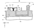
- the ink in the printing material storage unit 70 is supplied to the cartridge mounting unit 42 as follows.
- FIG. 11 is a first cross-sectional view showing a state in which the ink in the printing material storage unit 70 is supplied to the cartridge mounting unit 42.
- FIG. 12 is a second cross-sectional view showing how the ink in the printing material storage unit 70 is supplied to the cartridge mounting unit 42.
- 11 and 12 the illustration of the lever member 120, the regulating portion 116 of the pressure receiving plate 112, and the like is omitted for easy understanding.
- a supply pump (not shown) is built in the cartridge mounting portion 42, and sucks ink from the cartridge 50 side and pumps the ink toward the carriage 20.
- FIG. 11 shows a state when the supply pump of the cartridge mounting part 42 is not operating
- FIG. 12 shows a state when the supply pump of the cartridge mounting part 42 is operating. Yes.
- the spring 108 pushes out the film 118 so as to increase the volume of the detection chamber 100.
- ink flows into the detection chamber 100 through the inflow passage 140 that connects the printing material container 70 and the inflow port 102.
- a check valve 106 is provided at the inflow port 102 to allow ink to flow into the detection chamber 100 and prevent backflow.
- the arrow of the broken line in a figure represents the flow of ink.
- the inner diameter of the outflow passage 142 is set to be larger than the inner diameter of the inflow passage 140, so that the ink flowing into the detection chamber 100 with respect to the outflow of ink from the detection chamber 100.
- the inflow cannot catch up, and the detection chamber 100 has a negative pressure. Therefore, as shown in FIG. 12, the film 118 is deformed so as to be drawn inside the detection chamber 100 against the force of the spring 108.
- the negative pressure generated in the detection chamber 100 is gradually eliminated by the ink in the printing material container 70 flowing into the detection chamber 100 through the inflow passage 140. Then, the film 118 is pushed out of the detection chamber 100 again by the force of the spring 108, and the volume of the detection chamber 100 is restored. As a result, after a predetermined time has elapsed since the supply pump of the cartridge mounting portion 42 was stopped, the state shown in FIG. 11 is restored. When the supply pump of the cartridge mounting portion 42 is activated again, the pressure in the detection chamber 100 becomes negative, and the film 118 is drawn into the detection chamber 100 as shown in FIG.
- the ink in the printing material container 70 When the ink in the printing material container 70 is consumed and disappears, the ink does not flow into the detection chamber 100 from the printing material container 70 even if the detection chamber 100 has a negative pressure. That is, even after a predetermined time has elapsed after the supply pump of the cartridge mounting portion 42 has stopped, the negative pressure in the detection chamber 100 is not eliminated, and the film 118 remains inside the detection chamber 100 as shown in FIG. Will remain in the state of being drawn into.
- the film 118 that constitutes one end surface of the detection chamber 100 remains deformed so as to be drawn into the detection chamber 100. That is, by detecting the displacement of the film 118 using the detection mechanism 300 (see FIG. 4), it is possible to detect that the ink in the printing material storage unit 70 has run out. However, since the displacement amount of the film 118 of this embodiment is small, the displacement amount is amplified using the following lever member 120.
- FIG. 13 is an explanatory view showing the configuration of the lever member 120 provided in the cartridge 50 of the present embodiment.
- a shaft hole 122 is provided on one end side of the lever member 120.
- the lever member 120 is rotatable around the shaft hole 122 in a state where the shaft pin 126 (FIG. 10) provided on the outer surface of the detection chamber 100 is fitted in the shaft hole 122.
- a guide hole 124 is provided on the other end side of the lever member 120, and a guide pin 128 (FIG. 10) fixed to the printing material supply unit 74 is inserted into the guide hole 124.
- the guide pin 128 moves along the guide hole 124 to guide the rotation operation of the lever member 120, so that the rotation of the lever member 120 is regulated with high accuracy. be able to.
- a hemispherical convex portion 130 that contacts the film 118 is provided on the surface of the lever member 120 facing the film 118, and the surface of the lever member 120 opposite to the side facing the film 118 is provided on the surface opposite to the film 118.
- a contact portion 132 is provided as a convex portion with which the tip 45c (see FIGS. 3 and 4) of the rod 45 provided on the cartridge mounting portion 42 side contacts.
- a distance D2 from the shaft hole 122 serving as a fulcrum of the lever member 120 to the contact portion 132 is set to be larger than a distance D1 from the shaft hole 122 to the convex portion 130.
- the displacement amount of the film 118 amplified by the lever member 120 is transmitted to the rod 45 provided inside the cartridge mounting portion 42 as described above.
- the displacement amount of the film 118 is amplified, and the amplified displacement amount becomes the movement distance of the rod 45. Therefore, it is required that the rod 45 abuts on the lever member 120 at an accurate designed position so that the detection of the ink end using the detection mechanism 300 is performed correctly.
- FIG. 14 is a first diagram for explaining the detection of the ink end, and shows a state in which the cartridge 50 is not mounted, particularly a state before the cartridge 50 in which sufficient ink remains is mounted.
- FIG. 15 is a second diagram for explaining the detection of the ink end, and shows a state when the cartridge 50 in a state where a sufficient amount of ink remains is mounted on the cartridge mounting portion 42.
- FIG. 16 is a third diagram for explaining the detection of the ink end, and is a state when the ink in the ink cartridge 50 mounted on the cartridge mounting portion 42 runs out or when the ink is low (at the time of ink end). Is shown.
- the spring 49 urges the rod 45 toward the cartridge 50.
- the rod 45 is moved toward the cartridge 50 by the force of the spring 49. Therefore, the light shielding part 138 of the rod 45 is inserted between the light emitting part and the light receiving part of the sensor 136, and the light from the light emitting part is blocked.
- This state is the same as the ink end state described later with reference to FIG.
- the printer 10 is controlled so that printing is impossible in this state.
- the cartridge 50 is mounted on the cartridge mounting portion 42, the cartridge 50 is inserted in the direction of the arrow in the drawing, that is, in the ⁇ Y axis direction.
- the cartridge 50 shown in FIG. 14 is in a state where a sufficient amount of ink remains.
- the tip 45c of the rod 45 is brought into contact with the contact portion 132 of the lever member 120 provided on the cartridge 50 side. Abut.
- the biasing force A ′ applied to the contact portion 132 of the lever member 120 by the biasing force A of the spring 108 of the cartridge 50 is set to be larger than the biasing force B of the spring 49.
- the sensor 136 is in a state of transmitting light. As described above, the sensor 136 can detect that the cartridge 50 is mounted on the cartridge mounting portion 42 based on the change from the light blocking state to the transmitting state due to the movement of the light blocking portion 138 of the rod 45. It is. This state is maintained until the ink in the printing material container 70 is exhausted or the remaining ink is reduced. In this state, the printer 10 is controlled to enable printing as long as there is no other abnormality in the cartridge 50 or the printer 10. In addition, since the technique regarding the type of “other abnormality” and its detection method is well known, the description is omitted here.
- the ink in the printing material container 70 runs out (or decreases)
- the ink does not flow from the printing material container 70 into the detection chamber 100, and a negative pressure is applied to the detection chamber 100.
- the urging force A of the spring 108 of the cartridge 50 is set to be smaller than the force C caused by the negative pressure generated when the printing material storage unit 70 runs out of ink (or when the remaining amount decreases). Therefore, the film C remains in the state of being pulled inside the detection chamber 100 by this force C.
- the rod 45 is displaced in the + Y-axis direction by the biasing force B of the spring 49.
- the rod 45 rotates the lever member 120 following the deformation of the film 118, and the lever member 120 is held in a closed state.
- the rod 45 moves to the cartridge 50 side, and the light shielding portion 138 of the rod 45 is inserted between the light emitting portion and the light receiving portion of the sensor 136.
- the sensor 136 Based on the fact that the light is blocked by the light blocking portion 138 of the rod 45 (the rod 45 has moved), the sensor 136 has run out of ink in the printing material container 70 or has run out of ink (ink end). Is detected.
- the printer 10 is controlled so that printing is impossible in this state.
- the cartridge 50 of this embodiment is not provided with a piezoelectric detection mechanism for detecting the ink end.
- electric conduction means wiring, electrode terminals, etc.
- the cartridge 50 can be reduced in size.
- the printing apparatus to which the cartridge is mounted can be reduced in size.
- the manufacturing cost of the cartridge 50 can be suppressed. Further, by suppressing the manufacturing cost of the replaceable cartridge 50 that is manufactured in large quantities compared to the printer 10, the manufacturing cost of the entire printing material supply system 1 can also be suppressed.
- the first insertion hole 53 into which the rod 45 is inserted is provided in the middle of the front surface 532 between the first side surface 534 and the second side surface 536 (FIG. 7). That is, the rod 45 used for detecting the end of the printing material is inserted into the first insertion hole 53, whereby the cartridge 50 is positioned with respect to the cartridge mounting portion 42 at an intermediate position in the longitudinal direction of the front surface 532 of the cartridge. . Thereby, the position shift of the cartridge 50 with respect to the rod 45 can be suppressed, and the detection of the ink end by the detection mechanism 300 can be accurately performed.
- the front surface 532 of the cartridge 50 is larger in the Z-axis direction than in the X-axis direction. Therefore, when the first insertion hole 53 is provided to be biased to one of the first side surface 534 and the second side surface 536, it may be difficult to accurately position the cartridge 50. For example, when the first insertion hole 53 is provided so as to be biased toward the first side surface 534, the rod 45 is inserted into the first insertion hole 53, thereby causing wobble or rattling on the first side surface 534 side. Although it can be suppressed, the wobbling and rattling on the second side surface 534 side away from the first insertion hole 53 cannot be suppressed, and the degree thereof increases.
- the 2nd side 534 side may shift from the mounting position which should be originally located.
- the first insertion hole 53 is provided at an intermediate position between the first side surface 534 and the second side surface 536, the first side surface 534 side and the second side surface 536 side are wobbled. It is possible to make the same level and to make it smaller. Therefore, the cartridge 50 can be accurately and efficiently positioned with respect to the cartridge mounting portion 42.
- the rod 45 used for detecting the ink end also serves as a member for positioning the cartridge 50 with respect to the cartridge mounting portion 42. Therefore, the printing material supply system 1 does not need to newly include a positioning member. Thereby, the number of parts of the printing material supply system 1 can be reduced. In addition, since the cartridge 50 is positioned with respect to the cartridge mounting portion 42 using the rod 45 used for detecting the end of the ink, there is no need to provide a separate positioning member, and the number of parts can be reduced. it can. In addition, the printing apparatus 10 to which the cartridge 50 is mounted can be downsized.
- the rod cover 47 is also inserted into the first insertion hole 53. Accordingly, the rod 45 can be prevented from coming into contact with the wall forming the first insertion hole 53, so that the rod 45 can be smoothly moved in accordance with the change in the volume of the detection chamber 100. As a result, the ink end can be detected more accurately.
- the cartridge case 72 includes a cap 82 and a protective container 84.
- the protective material 84 accommodates the printing material accommodation unit 70.
- the cap 82 is provided with a second insertion hole 51 and a first insertion hole 53 into which a member provided in the cartridge mounting portion 42 is inserted.
- the protective container 84 side is heavier as a whole than the cap 82 side.
- the protective container 84 for storing the liquid storage unit 70, the cap 82, and the protective container 84 are separate members, the protective container 84 is capped by the clearance between the cap 82 and the protective container 84. It can be configured to be slightly movable with respect to 82. Even if the weight of the printing material container 70 is large, only the portion of the protective container 84 is inclined, and the cap 82 can be maintained in a correct posture without being inclined. Thereby, in the mounting state, the possibility that the positions of the second insertion holes 51 and the first insertion holes 53 provided in the cap 82 with respect to the cartridge mounting portion 42 are shifted from the designed correct positions can be reduced.
- the cartridge-side terminal group 202 is provided on the cap 82 that reduces the possibility of being displaced from the correct position. Thereby, the electrical connection between the cartridge side terminal group 202 and the apparatus side terminal group 414 in the mounted state can be stably achieved.
- the first side surface 534a of the cap 82 is provided with a first convex portion 56a protruding in the + Z direction, and the second side surface 536 of the cap has ⁇ Z A second convex portion 58a protruding in the direction is provided.
- the first convex portion 56a is provided on the first apparatus-side side wall portion 434 when the cartridge 50 is inserted into the cartridge mounting portion 42 (see FIGS. 2 and 3) and when the cartridge 50 is removed from the cartridge mounting portion 42. It is guided by the first rail 402 (see FIGS. 2 and 3).
- the second convex portion 58a is provided on the second device side wall portion 436 when the cartridge 50 is inserted into the cartridge mounting portion 42 (see FIGS. 2 and 3) and when the cartridge 50 is removed from the cartridge mounting portion 42. It is guided by the second rail 404 (see FIGS. 2 and 3). And the dimension Tc of the X-axis direction of the 1st convex part 56a differs from the dimension Td of the X-axis direction of the 2nd convex part 58a.
- the dimension Ta in the X-axis direction of the first rail 402 is made to correspond to the dimension Tc in the X-axis direction of the first convex part
- the dimension Tb in the X-axis direction of the second rail 404 is made equal to the X-axis direction of the second convex part. Therefore, it is possible to prevent the cartridge 50 from being mounted in an erroneous state in which the positions of the first side surface 534 and the second side surface 536 of the cartridge 50 are reversed.
- the opening end 53f on the ⁇ Y-axis direction side of the first insertion hole 53 is located at a position where the rod 45 is inserted before the printing material supply pipe 46 is inserted into the printing material supply port 78f. (FIGS. 8 and 9A). Therefore, after the cartridge 50 is guided to the correct position in the cartridge mounting portion 42 by the rod 45, the printing material supply pipe 46 and the printing material supply port 78f are connected. Therefore, it is possible to prevent the printing material supply pipe 46 from being damaged when the tip 46c (FIG. 3) of the printing material supply pipe 46 collides with a position different from the printing material supply port 78f of the cartridge 50. Further, since the positional deviation between the central axis Ca (see FIG.
- the opening end 53f of the first insertion hole 53 has a tip 46c of the printing material supply port printing material supply pipe 46 and a tip 45c of the rod 45 on the + Y-axis direction side as Y. At the same position P in the axial direction.
- the present embodiment as shown in FIG.
- the opening end 53f of the first insertion hole 53 is provided on the ⁇ Y-axis direction side with respect to the printing material supply port 78f. Can be achieved. That is, before the printing material supply pipe 46 is inserted into the printing material supply port 78f, the rod 45 is first inserted into the first insertion hole 53, and the cartridge 50 can be positioned.
- the cartridge 50 of this embodiment includes a cartridge-side identification member 520 for identifying the type of cartridge depending on whether or not it can be fitted into the apparatus-side identification unit 420.
- the identification members 520 and 420 hit each other, and further insertion can be hindered. Therefore, the possibility that the wrong type of cartridge 50 is connected to the printing material supply pipe 46 can be reduced. As a result, the possibility that ink of a color different from the original color will circulate in the printing material supply pipe 46 can be reduced. Further, as shown in FIGS.
- the + Y-axis direction end 422c of the apparatus-side identification member 420 is at the same position P in the Y-axis direction.
- the front end surface 520f of the cartridge-side identification member 520 is provided on the + Y axis direction side with respect to the opening end 53f of the first insertion hole 53, and ⁇ Y than the printing material supply port 78f. Since it is provided on the axial direction side, the mounting mode can be easily achieved.
- the cartridge side identification member 520, the apparatus side identification member 420, can begin to fit.
- the cartridge-side identification member 520 and the apparatus-side identification member 420 can be formed with a simple configuration in which ribs 522 and 422 are used.
- the first insertion hole 53 has a predetermined length in the Y-axis direction, and the area of the opening end 53f on the ⁇ Y-axis direction side is + Y-axis. It is smaller than the area of the opening end 53g on the direction side. That is, the opening end 53f on the ⁇ Y-axis direction side that first receives the rod 45 is wider than the opening end 53g on the + Y-axis direction side that is the other opening end. Therefore, the cartridge 50 can be positioned with higher accuracy by inserting the rod 45 to the opening end 53g on the + Y-axis direction side while making the rod 45 easily received in the first insertion hole 53.
- the first insertion hole 53 includes an end portion 53y extending from the connecting portion 53h to the opening end 53f on the ⁇ Y axis direction side, and a connecting portion 53b. And the other end portion 53t reaching the opening end 53g on the + Y-axis direction side.
- the one end side portion 53y is a truncated cone whose cross section parallel to the X axis and the Z axis is a circle. As shown in FIGS.
- the other end portion 53t has a cross section parallel to the X axis and the Z axis facing a pair of straight lines 53p and 53p facing in the Z axis direction in the X axis direction. It is a column shape which is a shape formed by a combination of two arcs 53q and 53q.
- the distance between the pair of straight lines 53p and 53p constituting the cross section of the other end side portion 53t is smaller than the diameter of the circle constituting the cross section of the one end side portion 53y.
- the diameter of the pair of arcs 53q and 53q constituting the cross section of the other end side portion 53t is the same as the diameter of the pair of arcs that exercise the cross section of the one end side portion 53y.
- the cross-sectional area gradually decreases from the opening end 53f on the ⁇ Y axis direction side toward the connection portion 53h.
- the shape of the cross section changes at the connection portion 53h, that is, the inlet of the other end side portion 53g, and only the dimension in the Z-axis direction becomes small.
- the dimension in the X-axis direction does not change.
- the rod 45 can be smoothly guided from the one end side portion 53y to the other end side portion 53t.
- a gap is provided between the rod 45 and the first insertion hole 53 so that the rod 45 can be smoothly guided to the opening end 53g on the + Y-axis direction side.
- the position of the rod 45 is stabilized, and the cartridge 50 can be accurately positioned with respect to the cartridge mounting portion 42.
- the positioning of the cartridge 50 with respect to the cartridge mounting portion 42 in the X-axis direction is performed by the second cartridge convex portion 58 entering the second rail 404. Further, the positioning of the cartridge 50 with respect to the cartridge mounting portion 42 on the ⁇ Y-axis direction side is performed by bringing the cartridge 50 (the front surface 532 in this embodiment) into contact with the regulating member 406.
- FIG. 17 is a view for explaining the cartridge 50a of the first modification.
- the X-axis direction dimensions of the first cartridge convex portion 56 and the second cartridge convex portion 58 are constant in all portions. However, a portion of the X-axis direction size may be increased.
- a protruding portion 57 that protrudes in the X-axis direction is provided on the rear surface 540 side (+ Y-axis direction side).
- the dimension Te in the X-axis direction of the first cartridge protrusion 56 at the portion where the protrusion 57 is provided is also smaller than the dimension Ta in the X-axis direction of the first rail 402 (FIG. 2).
- the second container-side convex portion 58b similarly has an X-axis dimension (referred to as Tf) that is larger than the X-axis dimension Tb of the second rail 404 (FIG. 2).
- Tf X-axis dimension
- Tb X-axis dimension
- the dimension in the X-axis direction has a relationship of Tc ⁇ Te ⁇ Ta ⁇ Td ⁇ Tf ⁇ Tb.
- the cartridge 50a when the cartridge 50a is mounted on the cartridge mounting portion 42, a certain amount of clearance is provided between the cartridge convex portions 56 and 58 and the rails 402 and 404, so that the cartridge 50a can be mounted more smoothly.
- the portion that can be inserted into the portion 42 and has a large dimension in the X-axis direction after mounting (the portion where the protruding portion 57 is located) cooperates with the first rails 402 and 404, so that the X on the + Y-axis direction side of the cartridge 50a Axial movement can be restricted.
- the first insertion hole 53 is provided at a position intermediate between the first side surface 534 and the second side surface 536 in the front surface 532, but further, in the front surface 532, It is preferable to be provided at an intermediate position with respect to the fourth side surface 539. By doing so, the cartridge 50 using the first insertion hole 53 and the rod 45 can be positioned more accurately.
- the “intermediate position between the third side surface 538 and the fourth side surface 539” does not have to be completely in the middle, and may not be disposed so as to be biased to one of the side surfaces.
- the “intermediate position” is a position where the central axis Ce of the first insertion hole 53 is within 10% of the center position with respect to the distance between the third side surface 538 and the fourth side surface 539 in the X-axis direction. including.
- the “intermediate position” is within 7.5% of the center position with respect to the distance in the X-axis direction between the third side surface 538 and the fourth side surface 539 so that the central axis Ce is arranged more intermediately. It is preferable to include a position within the range.
- the opening end 53g on the + Y axis direction side of the first insertion hole 53 is parallel to a plane parallel to the X axis and the Z axis, but may be inclined with respect to this plane.
- the contact portion 132 of the lever 120 protrudes in the ⁇ Y direction. Therefore, the portion on the + Z axis direction side is more on the ⁇ Y axis direction side than the portion on the ⁇ Z axis direction side so that the contact portion of the lever 120 does not interfere with the opening end 53g of the first insertion hole 53 on the + Y axis direction side.
- the opening end 53g may be inclined so as to retract backward.
- the “area of the opening end 53g” when the opening end 53g is inclined is the area when the opening end 53g is projected onto a plane parallel to the X axis and the Z axis.
- the present invention can be applied not only to an ink jet printer and its ink cartridge but also to an arbitrary printing apparatus that ejects liquid other than ink and its liquid container.
- the present invention can be applied to the following various printing apparatuses and their liquid containers.
- Image recording device such as a facsimile device
- Printing device for ejecting color material used for manufacturing a color filter for an image display device such as a liquid crystal display
- a printing device that ejects electrode materials used for electrode formation
- a printing device that ejects a liquid containing bioorganic materials used in biochip manufacturing
- a sample printing device as a precision pipette
- Lubricating oil printing device (7)
- Resin liquid printing device (8)
- Printing device for injecting lubricating oil pinpoint to precision machines such as watches and cameras (9) Micro hemispherical lens used for optical communication elements, etc.
- Optical lens A printing device that injects a transparent resin liquid such as an ultraviolet curable resin liquid onto the substrate to form an optical lens.
- printing apparatus which ejects an alkaline etching solution (11) any other printing apparatus including a liquid ejecting head ejecting a minute amount of liquid droplet
- droplet refers to the state of the liquid ejected from the printing apparatus, and includes those that have a tail in the form of particles, tears, or threads.
- the “liquid” here may be any material that can be ejected by the printing apparatus.
- the “liquid” may be a material in a state in which the substance is in a liquid phase, such as a material in a liquid state having high or low viscosity, and sol, gel water, other inorganic solvents, organic solvents, solutions, Liquid materials such as liquid resins and liquid metals (metal melts) are also included in the “liquid”.
- liquid includes not only a liquid as one state of a substance but also a liquid in which particles of a functional material made of a solid such as a pigment or metal particles are dissolved, dispersed or mixed in a solvent.
- representative examples of the liquid include ink and liquid crystal as described in the above embodiment.
- the ink includes various water-based inks and oil-based inks as well as various liquid compositions such as gel inks and hot melt inks.
- First insertion hole 53f Open end 53g ... Open end 53h ... Connection part 53p ... Straight line 53q ... Arc 53t ... Others End side part 53y ... One end side part 55 ... Corner part 5 6 ... 1st cartridge convex part 56a ... 1st convex part 56b ... 1st container side convex part 56c ... Space part 57 ... Protrusion part 58 ... 2nd cartridge convex part 58a ... 2nd convex part 58b ... 2nd Container side convex part 58c ... Space part 60 ... Control part 70 ... Printing material container 72 ... Cartridge case 74 ... Printing material supply unit 75 ... Opening 76 ... Printing material injection port 77 ...
- First side 534a First side 534 of the cap Protective container first side 536 Second side 536a
- Cap second side 536b Protective container second side 538
- Third side 539 Fourth side 540
- a biasing force A 'Biasing force B ... Biasing force C ... Force due to negative pressure
- Ca Center axis Cb . Center axis Ce ... Center axis P ... Position Ta ... Dimension in X axis direction Tb ... Dimension in X axis direction Tc ... Dimension in X axis direction Td ... X axis direction
- Dimensions Te ... Dimensions in the X-axis direction Tf ... Dimensions in the X-axis direction (not shown)
- Th ... Distance Tha ... Distance Thb ... Distance Vh ... Center position
Abstract
Priority Applications (10)
| Application Number | Priority Date | Filing Date | Title |
|---|---|---|---|
| ES11851357.1T ES2664893T3 (es) | 2010-12-22 | 2011-12-19 | Cartucho |
| MX2013003180A MX2013003180A (es) | 2010-12-22 | 2011-12-19 | Cartucho. |
| KR1020137006717A KR101441262B1 (ko) | 2010-12-22 | 2011-12-19 | 카트리지 |
| PL11851357T PL2657031T3 (pl) | 2010-12-22 | 2011-12-19 | Kartridż |
| AU2011346241A AU2011346241B2 (en) | 2010-12-22 | 2011-12-19 | Cartridge |
| EP11851357.1A EP2657031B1 (fr) | 2010-12-22 | 2011-12-19 | Cartouche |
| CA2809231A CA2809231C (fr) | 2010-12-22 | 2011-12-19 | Cartouche |
| BR112013005898A BR112013005898A2 (pt) | 2010-12-22 | 2011-12-19 | cartucho |
| JP2012549630A JP5545377B2 (ja) | 2010-12-22 | 2011-12-19 | カートリッジ |
| RU2013111525/12A RU2520941C1 (ru) | 2010-12-22 | 2011-12-19 | Картридж |
Applications Claiming Priority (2)
| Application Number | Priority Date | Filing Date | Title |
|---|---|---|---|
| JP2010285972 | 2010-12-22 | ||
| JP2010-285972 | 2010-12-22 |
Publications (1)
| Publication Number | Publication Date |
|---|---|
| WO2012086171A1 true WO2012086171A1 (fr) | 2012-06-28 |
Family
ID=46313463
Family Applications (1)
| Application Number | Title | Priority Date | Filing Date |
|---|---|---|---|
| PCT/JP2011/007077 WO2012086171A1 (fr) | 2010-12-22 | 2011-12-19 | Cartouche |
Country Status (16)
| Country | Link |
|---|---|
| US (2) | US8434859B2 (fr) |
| EP (2) | EP3312012A1 (fr) |
| JP (4) | JP5545377B2 (fr) |
| KR (1) | KR101441262B1 (fr) |
| CN (3) | CN202742815U (fr) |
| AU (1) | AU2011346241B2 (fr) |
| BR (1) | BR112013005898A2 (fr) |
| CA (1) | CA2809231C (fr) |
| DE (1) | DE202011110616U1 (fr) |
| ES (1) | ES2664893T3 (fr) |
| MX (1) | MX2013003180A (fr) |
| PL (1) | PL2657031T3 (fr) |
| RU (1) | RU2520941C1 (fr) |
| TR (1) | TR201802135T4 (fr) |
| TW (1) | TWI523767B (fr) |
| WO (1) | WO2012086171A1 (fr) |
Cited By (5)
| Publication number | Priority date | Publication date | Assignee | Title |
|---|---|---|---|---|
| JP2014043016A (ja) * | 2012-08-24 | 2014-03-13 | Brother Ind Ltd | 印刷流体供給装置及び印刷流体カートリッジ |
| US8807723B2 (en) | 2012-05-21 | 2014-08-19 | Seiko Epson Corporation | Printing material holding container |
| JP2015202582A (ja) * | 2014-04-11 | 2015-11-16 | セイコーエプソン株式会社 | 液体容器、アダプター、ならびに液体噴射装置 |
| JP2017205895A (ja) * | 2016-05-16 | 2017-11-24 | キヤノン株式会社 | 液体吐出装置および液体補給容器 |
| EP4063130A1 (fr) | 2021-03-19 | 2022-09-28 | Seiko Epson Corporation | Cartouche |
Families Citing this family (22)
| Publication number | Priority date | Publication date | Assignee | Title |
|---|---|---|---|---|
| ES2664893T3 (es) * | 2010-12-22 | 2018-04-23 | Seiko Epson Corporation | Cartucho |
| JP5884305B2 (ja) * | 2011-06-13 | 2016-03-15 | セイコーエプソン株式会社 | 液体容器、および液体検出システム |
| JP2013000986A (ja) * | 2011-06-17 | 2013-01-07 | Brother Industries Ltd | インクジェットプリンタ |
| DE202013012026U1 (de) * | 2012-01-13 | 2015-02-03 | Seiko Epson Corporation | Kartusche, Druckmaterialzufuhrsystem, Druckvorrichtung, Flüssigkeitsaufnahmebehälter, ein Drucksystem und eine Anschlussverbindungsstruktur |
| US8960871B2 (en) | 2012-01-13 | 2015-02-24 | Seiko Epson Corporation | Mounting member, liquid container with mounting member, and liquid supply system |
| US8646889B2 (en) | 2012-01-13 | 2014-02-11 | Seiko Epson Corporation | Cartridge and printing device |
| US8931887B2 (en) | 2012-01-13 | 2015-01-13 | Seiko Epson Corporation | Liquid consumption apparatus, liquid supply member, and liquid supply system |
| US9440755B2 (en) * | 2012-01-13 | 2016-09-13 | Seiko Epson Corporation | Liquid container and liquid consumption apparatus |
| JP6182839B2 (ja) | 2012-08-31 | 2017-08-23 | セイコーエプソン株式会社 | インク供給装置 |
| GB2526033B (en) * | 2013-03-20 | 2020-01-01 | Hewlett Packard Development Co | Printhead assembly with fluid interconnect cover |
| DE112014004288T5 (de) | 2013-09-18 | 2016-06-09 | Canon Kabushiki Kaisha | Tintenkartusche und Tintenstrahldrucker |
| CN105751705B (zh) * | 2015-01-06 | 2019-08-30 | 精工爱普生株式会社 | 液体供给单元 |
| EP3663092B1 (fr) * | 2016-06-10 | 2022-08-24 | Seiko Epson Corporation | Utilisation d'un récipient de recharge d'encre |
| CN107554079B (zh) * | 2016-06-30 | 2019-06-07 | 珠海纳思达企业管理有限公司 | 一种打印机以及打印机用耗材容器插入方法 |
| JP6961919B2 (ja) * | 2016-09-30 | 2021-11-05 | ブラザー工業株式会社 | 液体カートリッジ及び液体消費装置 |
| JP7005942B2 (ja) * | 2017-06-01 | 2022-01-24 | 京セラドキュメントソリューションズ株式会社 | 廃インク貯留機構およびそれを備えたインクジェット記録装置 |
| CN111356591B (zh) * | 2017-11-20 | 2022-06-07 | 精工爱普生株式会社 | 容器以及液体喷射装置 |
| EP3765298A1 (fr) * | 2018-08-30 | 2021-01-20 | Hewlett-Packard Development Company, L.P. | Seringues avec pistons |
| JP7159702B2 (ja) * | 2018-08-31 | 2022-10-25 | ブラザー工業株式会社 | システム |
| JP2022001417A (ja) | 2020-06-22 | 2022-01-06 | セイコーエプソン株式会社 | 液体噴射システム、液体貯留機構 |
| CN214606596U (zh) * | 2020-09-21 | 2021-11-05 | 珠海纳思达企业管理有限公司 | 一种墨量检测机构、墨盒以及打印机 |
| JP2022144519A (ja) * | 2021-03-19 | 2022-10-03 | セイコーエプソン株式会社 | カートリッジ |
Citations (5)
| Publication number | Priority date | Publication date | Assignee | Title |
|---|---|---|---|---|
| JP2007136807A (ja) | 2005-11-17 | 2007-06-07 | Canon Inc | インク供給機構及びこれを備えたインクジェット記録装置 |
| JP2008270750A (ja) | 2007-03-23 | 2008-11-06 | Murata Mfg Co Ltd | 導電性ペースト、積層セラミック電子部品および多層セラミック基板 |
| JP2010241098A (ja) * | 2009-03-18 | 2010-10-28 | Ricoh Co Ltd | インクカートリッジ及び画像形成装置 |
| JP2010285972A (ja) | 2009-06-15 | 2010-12-24 | Rinnai Corp | 自吸式ポンプ |
| JP2011016236A (ja) * | 2009-07-07 | 2011-01-27 | Ricoh Co Ltd | インク充填用治具、インク充填装置、インク充填方法、インク充填キット |
Family Cites Families (55)
| Publication number | Priority date | Publication date | Assignee | Title |
|---|---|---|---|---|
| JPS59174244U (ja) * | 1983-05-07 | 1984-11-21 | 三洋電機株式会社 | 液体供給装置 |
| JPS6022346U (ja) * | 1983-07-20 | 1985-02-15 | 三洋電機株式会社 | 液体供給装置 |
| US5221935A (en) * | 1990-02-15 | 1993-06-22 | Canon Kabushiki Kaisha | Waste ink receiving cartridge and ink recording apparatus using said cartridge |
| EP0523569B1 (fr) * | 1991-07-12 | 1996-01-03 | Canon Kabushiki Kaisha | Système d'enregistrement par jet d'encre |
| US5359357A (en) * | 1992-03-19 | 1994-10-25 | Fuji Xerox Co., Ltd. | Ink-jet recording apparatus |
| JP3110872B2 (ja) * | 1992-06-24 | 2000-11-20 | キヤノン株式会社 | インクジェット記録装置 |
| US6142617A (en) * | 1995-04-27 | 2000-11-07 | Hewlett-Packard Company | Ink container configured for use with compact supply station |
| CA2234353A1 (fr) * | 1997-04-11 | 1998-10-11 | David C. Kamp | Dispositif de confinement et de distribution de liquide avec fixation amelioree au chassis d'un sac contenant du liquide |
| JP3493964B2 (ja) * | 1997-08-28 | 2004-02-03 | セイコーエプソン株式会社 | インクジェットプリンタのインクカートリッジ挿入機構 |
| EP1604832A3 (fr) * | 1998-02-13 | 2006-02-22 | Seiko Epson Corporation | Tête d'impression avec reservoir secondaire connecté par une valve anti-refoulement |
| JP3928312B2 (ja) * | 1999-09-21 | 2007-06-13 | 富士ゼロックス株式会社 | インクジェット記録装置 |
| WO2001053104A1 (fr) * | 2000-01-21 | 2001-07-26 | Seiko Epson Corporation | Cartouche d'encre pour dispositif d'enregistrement et dispositif d'enregistrement a jet d'encre |
| CN1799846B (zh) * | 2000-01-21 | 2010-06-09 | 精工爱普生株式会社 | 记录装置用墨盒及喷墨式记录装置 |
| CA2379725C (fr) * | 2001-04-03 | 2007-06-12 | Seiko Epson Corporation | Cartouche a encre |
| US7744202B2 (en) * | 2002-01-30 | 2010-06-29 | Hewlett-Packard Development Company, L.P. | Printing-fluid container |
| MXPA03002490A (es) * | 2002-03-20 | 2004-10-15 | Seiko Epson Corp | Cartucho para tinta y soporte de cartucho para tinta. |
| JP4133154B2 (ja) * | 2002-09-19 | 2008-08-13 | 株式会社リコー | インクカートリッジ及びインクジェットプリンタ |
| JP3919734B2 (ja) * | 2002-12-06 | 2007-05-30 | 株式会社リコー | インクカートリッジ及びその筺体、画像形成装置 |
| JP4356335B2 (ja) * | 2003-03-11 | 2009-11-04 | ブラザー工業株式会社 | 液体供給装置 |
| JP2004276538A (ja) * | 2003-03-18 | 2004-10-07 | Ricoh Co Ltd | インク袋、インクカートリッジ及びインクジェット記録装置並びにインク充填方法、インク再充填方法、インクカートリッジの製造方法、インクカートリッジのリサイクル方法 |
| CA2461959C (fr) | 2003-03-26 | 2012-07-24 | Seiko Epson Corporation | Reservoir a liquide |
| JP4129742B2 (ja) * | 2003-07-02 | 2008-08-06 | セイコーエプソン株式会社 | 液体容器及びその製造方法 |
| JP2004306505A (ja) * | 2003-04-09 | 2004-11-04 | Brother Ind Ltd | インクパッケージ |
| JP2005022124A (ja) * | 2003-06-30 | 2005-01-27 | Fuji Xerox Co Ltd | インク供給装置、インク供給方法及び記録装置 |
| US7004564B2 (en) * | 2003-07-31 | 2006-02-28 | Hewlett-Packard Development Company, L.P. | Printing-fluid container |
| US20090035467A1 (en) * | 2003-08-12 | 2009-02-05 | Hideki Sekiguchi | Recording Liquid, Liquid Cartridge, Liquid Emitting Device and Liquid Emitting Method |
| US7234787B2 (en) * | 2004-01-08 | 2007-06-26 | Eastman Kodak Company | Liquid level detection method and apparatus |
| TWI233889B (en) * | 2004-06-02 | 2005-06-11 | Benq Corp | Ink cartridge positioning mechanism and method thereof |
| JP4321370B2 (ja) * | 2004-06-14 | 2009-08-26 | ブラザー工業株式会社 | インク充填方法 |
| JP2006035484A (ja) * | 2004-07-23 | 2006-02-09 | Seiko Epson Corp | 液体容器および液体残量検出方法 |
| CN1915674A (zh) | 2005-08-16 | 2007-02-21 | 精工爱普生株式会社 | 液体容器和液体喷射设备 |
| JP2007076363A (ja) * | 2005-08-16 | 2007-03-29 | Seiko Epson Corp | 液体収容体及び液体噴射装置 |
| JP2007196650A (ja) * | 2005-11-28 | 2007-08-09 | Brother Ind Ltd | インクカートリッジ |
| JP4973758B2 (ja) * | 2005-11-28 | 2012-07-11 | ブラザー工業株式会社 | インクジェット記録システム |
| JP2007210233A (ja) * | 2006-02-10 | 2007-08-23 | Ricoh Co Ltd | 装置本体に着脱される装置、画像形成装置 |
| JP4569507B2 (ja) * | 2006-03-31 | 2010-10-27 | ブラザー工業株式会社 | インクジェット記録装置 |
| JP4877028B2 (ja) | 2006-04-18 | 2012-02-15 | セイコーエプソン株式会社 | 液体収容容器 |
| JP4321562B2 (ja) * | 2006-08-08 | 2009-08-26 | セイコーエプソン株式会社 | 液体収容容器 |
| JP4946751B2 (ja) | 2006-11-06 | 2012-06-06 | セイコーエプソン株式会社 | 容器ホルダ、液体消費装置及び液体収容容器 |
| CN101535054B (zh) | 2006-11-06 | 2011-11-16 | 精工爱普生株式会社 | 液体容纳容器 |
| TW201738095A (zh) * | 2006-11-06 | 2017-11-01 | Seiko Epson Corp | 液體收容容器、容器夾持具、及液體消耗裝置 |
| JP2008230214A (ja) | 2007-02-19 | 2008-10-02 | Seiko Epson Corp | 流体導出部のシール構造体及びシール方法並びに流体収容容器、再充填流体収容容器及びその再充填方法 |
| JP2008213147A (ja) * | 2007-02-28 | 2008-09-18 | Brother Ind Ltd | 液体供給装置及び画像記録装置 |
| JP5018469B2 (ja) | 2007-03-30 | 2012-09-05 | セイコーエプソン株式会社 | 液体収容容器 |
| JP2009119853A (ja) | 2007-10-23 | 2009-06-04 | Seiko Epson Corp | 液体収容容器 |
| US20090102880A1 (en) * | 2007-10-23 | 2009-04-23 | Seiko Epson Corporation | Liquid Storing Container |
| DE202008007757U1 (de) * | 2008-06-03 | 2008-08-07 | Ninestar Image Co., Ltd., Zhuhai | Tintenpatrone und Vorrichtung mit Tintenpatrone |
| JP4907625B2 (ja) * | 2008-09-29 | 2012-04-04 | 株式会社リコー | インクカートリッジ及び画像形成装置 |
| CN101873936B (zh) * | 2008-09-29 | 2012-06-06 | 株式会社理光 | 墨水盒和成像设备 |
| CN101491975B (zh) * | 2009-02-20 | 2011-12-28 | 珠海纳思达电子科技有限公司 | 一种用于喷墨打印机的墨盒 |
| JP2010208038A (ja) | 2009-03-06 | 2010-09-24 | Seiko Epson Corp | 液体噴射装置及び液体収容容器 |
| DE202009003510U1 (de) * | 2009-03-15 | 2009-05-28 | Leier, Rolf | Behälter zur Aufnahme einer Flüssigkeit |
| JP5262950B2 (ja) * | 2009-04-21 | 2013-08-14 | セイコーエプソン株式会社 | 液体容器及び液体供給装置 |
| CN201645998U (zh) * | 2010-04-16 | 2010-11-24 | 珠海纳思达企业管理有限公司 | 一种用于喷墨打印机的墨盒 |
| ES2664893T3 (es) * | 2010-12-22 | 2018-04-23 | Seiko Epson Corporation | Cartucho |
-
2011
- 2011-12-19 ES ES11851357.1T patent/ES2664893T3/es active Active
- 2011-12-19 US US13/330,013 patent/US8434859B2/en active Active
- 2011-12-19 DE DE201120110616 patent/DE202011110616U1/de not_active Expired - Lifetime
- 2011-12-19 TR TR2018/02135T patent/TR201802135T4/tr unknown
- 2011-12-19 AU AU2011346241A patent/AU2011346241B2/en not_active Ceased
- 2011-12-19 MX MX2013003180A patent/MX2013003180A/es unknown
- 2011-12-19 JP JP2012549630A patent/JP5545377B2/ja active Active
- 2011-12-19 BR BR112013005898A patent/BR112013005898A2/pt not_active Application Discontinuation
- 2011-12-19 RU RU2013111525/12A patent/RU2520941C1/ru active
- 2011-12-19 PL PL11851357T patent/PL2657031T3/pl unknown
- 2011-12-19 EP EP17204020.6A patent/EP3312012A1/fr not_active Withdrawn
- 2011-12-19 EP EP11851357.1A patent/EP2657031B1/fr active Active
- 2011-12-19 KR KR1020137006717A patent/KR101441262B1/ko active IP Right Grant
- 2011-12-19 CA CA2809231A patent/CA2809231C/fr not_active Expired - Fee Related
- 2011-12-19 WO PCT/JP2011/007077 patent/WO2012086171A1/fr active Application Filing
- 2011-12-21 CN CN2011205639051U patent/CN202742815U/zh not_active Expired - Lifetime
- 2011-12-21 CN CN201110447863.XA patent/CN102555502B/zh active Active
- 2011-12-21 TW TW100147835A patent/TWI523767B/zh not_active IP Right Cessation
- 2011-12-21 CN CN201510508015.3A patent/CN105109208B/zh not_active Expired - Fee Related
-
2013
- 2013-05-03 US US13/886,445 patent/US8733915B2/en active Active
-
2014
- 2014-05-14 JP JP2014100069A patent/JP5790834B2/ja active Active
-
2015
- 2015-08-06 JP JP2015155569A patent/JP6075421B2/ja active Active
-
2017
- 2017-01-12 JP JP2017002975A patent/JP6358348B2/ja active Active
Patent Citations (5)
| Publication number | Priority date | Publication date | Assignee | Title |
|---|---|---|---|---|
| JP2007136807A (ja) | 2005-11-17 | 2007-06-07 | Canon Inc | インク供給機構及びこれを備えたインクジェット記録装置 |
| JP2008270750A (ja) | 2007-03-23 | 2008-11-06 | Murata Mfg Co Ltd | 導電性ペースト、積層セラミック電子部品および多層セラミック基板 |
| JP2010241098A (ja) * | 2009-03-18 | 2010-10-28 | Ricoh Co Ltd | インクカートリッジ及び画像形成装置 |
| JP2010285972A (ja) | 2009-06-15 | 2010-12-24 | Rinnai Corp | 自吸式ポンプ |
| JP2011016236A (ja) * | 2009-07-07 | 2011-01-27 | Ricoh Co Ltd | インク充填用治具、インク充填装置、インク充填方法、インク充填キット |
Cited By (10)
| Publication number | Priority date | Publication date | Assignee | Title |
|---|---|---|---|---|
| US8807723B2 (en) | 2012-05-21 | 2014-08-19 | Seiko Epson Corporation | Printing material holding container |
| US9044972B2 (en) | 2012-05-21 | 2015-06-02 | Seiko Epson Corporation | Printing material holding container |
| US9487014B2 (en) | 2012-05-21 | 2016-11-08 | Seiko Epson Corporation | Printing material holding container |
| JP2014043016A (ja) * | 2012-08-24 | 2014-03-13 | Brother Ind Ltd | 印刷流体供給装置及び印刷流体カートリッジ |
| US9315036B2 (en) | 2012-08-24 | 2016-04-19 | Brother Kogyo Kabushiki Kaisha | Ink cartridge |
| JP2015202582A (ja) * | 2014-04-11 | 2015-11-16 | セイコーエプソン株式会社 | 液体容器、アダプター、ならびに液体噴射装置 |
| JP2017205895A (ja) * | 2016-05-16 | 2017-11-24 | キヤノン株式会社 | 液体吐出装置および液体補給容器 |
| US10427412B2 (en) | 2016-05-16 | 2019-10-01 | Canon Kabushiki Kaisha | Liquid ejecting apparatus and liquid refilling container |
| EP4063130A1 (fr) | 2021-03-19 | 2022-09-28 | Seiko Epson Corporation | Cartouche |
| US11807015B2 (en) | 2021-03-19 | 2023-11-07 | Seiko Epson Corporation | Cartridge |
Also Published As
Similar Documents
| Publication | Publication Date | Title |
|---|---|---|
| JP6358348B2 (ja) | カートリッジ | |
| JP6409994B2 (ja) | カートリッジ | |
| JP6051595B2 (ja) | カートリッジ | |
| JP5942450B2 (ja) | 装着部材、装着部材を備える液体容器、及び、液体供給システム | |
| JP5927954B2 (ja) | カートリッジ及び印刷装置 | |
| JP2016164003A (ja) | 印刷材収容容器 | |
| JP6308245B2 (ja) | 印刷材収容容器 | |
| JP6161868B2 (ja) | カートリッジ |
Legal Events
| Date | Code | Title | Description |
|---|---|---|---|
| 121 | Ep: the epo has been informed by wipo that ep was designated in this application |
Ref document number: 11851357 Country of ref document: EP Kind code of ref document: A1 |
|
| ENP | Entry into the national phase |
Ref document number: 2012549630 Country of ref document: JP Kind code of ref document: A |
|
| ENP | Entry into the national phase |
Ref document number: 2809231 Country of ref document: CA |
|
| WWE | Wipo information: entry into national phase |
Ref document number: 2011851357 Country of ref document: EP |
|
| ENP | Entry into the national phase |
Ref document number: 20137006717 Country of ref document: KR Kind code of ref document: A |
|
| WWE | Wipo information: entry into national phase |
Ref document number: MX/A/2013/003180 Country of ref document: MX |
|
| ENP | Entry into the national phase |
Ref document number: 2011346241 Country of ref document: AU Date of ref document: 20111219 Kind code of ref document: A |
|
| NENP | Non-entry into the national phase |
Ref country code: DE |
|
| ENP | Entry into the national phase |
Ref document number: 2013111525 Country of ref document: RU Kind code of ref document: A |
|
| REG | Reference to national code |
Ref country code: BR Ref legal event code: B01A Ref document number: 112013005898 Country of ref document: BR |
|
| ENP | Entry into the national phase |
Ref document number: 112013005898 Country of ref document: BR Kind code of ref document: A2 Effective date: 20130312 |