EP4063130A1 - Cartouche - Google Patents
Cartouche Download PDFInfo
- Publication number
- EP4063130A1 EP4063130A1 EP22162792.0A EP22162792A EP4063130A1 EP 4063130 A1 EP4063130 A1 EP 4063130A1 EP 22162792 A EP22162792 A EP 22162792A EP 4063130 A1 EP4063130 A1 EP 4063130A1
- Authority
- EP
- European Patent Office
- Prior art keywords
- casing
- cartridge
- convex portion
- wall
- liquid
- Prior art date
- Legal status (The legal status is an assumption and is not a legal conclusion. Google has not performed a legal analysis and makes no representation as to the accuracy of the status listed.)
- Granted
Links
- 239000007788 liquid Substances 0.000 claims abstract description 194
- 238000007639 printing Methods 0.000 claims abstract description 60
- 238000003780 insertion Methods 0.000 description 22
- 230000037431 insertion Effects 0.000 description 22
- 238000000034 method Methods 0.000 description 17
- 238000010168 coupling process Methods 0.000 description 15
- 230000008569 process Effects 0.000 description 13
- 230000005484 gravity Effects 0.000 description 10
- 239000000463 material Substances 0.000 description 10
- 230000007246 mechanism Effects 0.000 description 10
- 238000003860 storage Methods 0.000 description 10
- 230000008878 coupling Effects 0.000 description 7
- 238000005859 coupling reaction Methods 0.000 description 7
- 239000000758 substrate Substances 0.000 description 7
- 238000004891 communication Methods 0.000 description 4
- 230000002093 peripheral effect Effects 0.000 description 4
- 229920005989 resin Polymers 0.000 description 4
- 239000011347 resin Substances 0.000 description 4
- XLYOFNOQVPJJNP-UHFFFAOYSA-N water Substances O XLYOFNOQVPJJNP-UHFFFAOYSA-N 0.000 description 4
- 238000004519 manufacturing process Methods 0.000 description 3
- -1 polypropylene Polymers 0.000 description 3
- 239000000126 substance Substances 0.000 description 3
- 239000004743 Polypropylene Substances 0.000 description 2
- 230000000994 depressogenic effect Effects 0.000 description 2
- 238000005401 electroluminescence Methods 0.000 description 2
- 239000004973 liquid crystal related substance Substances 0.000 description 2
- 239000010687 lubricating oil Substances 0.000 description 2
- 230000008531 maintenance mechanism Effects 0.000 description 2
- 230000003287 optical effect Effects 0.000 description 2
- 229920001155 polypropylene Polymers 0.000 description 2
- 229920003002 synthetic resin Polymers 0.000 description 2
- 239000000057 synthetic resin Substances 0.000 description 2
- 238000000018 DNA microarray Methods 0.000 description 1
- 238000009825 accumulation Methods 0.000 description 1
- 239000002253 acid Substances 0.000 description 1
- 230000008859 change Effects 0.000 description 1
- 239000003086 colorant Substances 0.000 description 1
- 238000004040 coloring Methods 0.000 description 1
- 230000000694 effects Effects 0.000 description 1
- 239000007772 electrode material Substances 0.000 description 1
- 238000005530 etching Methods 0.000 description 1
- 230000012447 hatching Effects 0.000 description 1
- 239000012943 hotmelt Substances 0.000 description 1
- 238000001746 injection moulding Methods 0.000 description 1
- 229910001867 inorganic solvent Inorganic materials 0.000 description 1
- 239000003049 inorganic solvent Substances 0.000 description 1
- 239000007791 liquid phase Substances 0.000 description 1
- 229910001338 liquidmetal Inorganic materials 0.000 description 1
- 238000012423 maintenance Methods 0.000 description 1
- 239000002923 metal particle Substances 0.000 description 1
- 239000000203 mixture Substances 0.000 description 1
- 239000003960 organic solvent Substances 0.000 description 1
- 239000002245 particle Substances 0.000 description 1
- 239000000049 pigment Substances 0.000 description 1
- 229920000139 polyethylene terephthalate Polymers 0.000 description 1
- 239000005020 polyethylene terephthalate Substances 0.000 description 1
- 230000000717 retained effect Effects 0.000 description 1
- 230000000630 rising effect Effects 0.000 description 1
- 239000007787 solid Substances 0.000 description 1
- 239000000243 solution Substances 0.000 description 1
- 239000002904 solvent Substances 0.000 description 1
Images


Classifications
-
- B—PERFORMING OPERATIONS; TRANSPORTING
- B41—PRINTING; LINING MACHINES; TYPEWRITERS; STAMPS
- B41J—TYPEWRITERS; SELECTIVE PRINTING MECHANISMS, i.e. MECHANISMS PRINTING OTHERWISE THAN FROM A FORME; CORRECTION OF TYPOGRAPHICAL ERRORS
- B41J2/00—Typewriters or selective printing mechanisms characterised by the printing or marking process for which they are designed
- B41J2/005—Typewriters or selective printing mechanisms characterised by the printing or marking process for which they are designed characterised by bringing liquid or particles selectively into contact with a printing material
- B41J2/01—Ink jet
- B41J2/17—Ink jet characterised by ink handling
- B41J2/175—Ink supply systems ; Circuit parts therefor
- B41J2/17503—Ink cartridges
- B41J2/17553—Outer structure
-
- B—PERFORMING OPERATIONS; TRANSPORTING
- B41—PRINTING; LINING MACHINES; TYPEWRITERS; STAMPS
- B41J—TYPEWRITERS; SELECTIVE PRINTING MECHANISMS, i.e. MECHANISMS PRINTING OTHERWISE THAN FROM A FORME; CORRECTION OF TYPOGRAPHICAL ERRORS
- B41J2/00—Typewriters or selective printing mechanisms characterised by the printing or marking process for which they are designed
- B41J2/005—Typewriters or selective printing mechanisms characterised by the printing or marking process for which they are designed characterised by bringing liquid or particles selectively into contact with a printing material
- B41J2/01—Ink jet
- B41J2/17—Ink jet characterised by ink handling
- B41J2/175—Ink supply systems ; Circuit parts therefor
- B41J2/17503—Ink cartridges
- B41J2/1752—Mounting within the printer
-
- B—PERFORMING OPERATIONS; TRANSPORTING
- B41—PRINTING; LINING MACHINES; TYPEWRITERS; STAMPS
- B41J—TYPEWRITERS; SELECTIVE PRINTING MECHANISMS, i.e. MECHANISMS PRINTING OTHERWISE THAN FROM A FORME; CORRECTION OF TYPOGRAPHICAL ERRORS
- B41J29/00—Details of, or accessories for, typewriters or selective printing mechanisms not otherwise provided for
- B41J29/02—Framework
-
- B—PERFORMING OPERATIONS; TRANSPORTING
- B41—PRINTING; LINING MACHINES; TYPEWRITERS; STAMPS
- B41J—TYPEWRITERS; SELECTIVE PRINTING MECHANISMS, i.e. MECHANISMS PRINTING OTHERWISE THAN FROM A FORME; CORRECTION OF TYPOGRAPHICAL ERRORS
- B41J29/00—Details of, or accessories for, typewriters or selective printing mechanisms not otherwise provided for
- B41J29/12—Guards, shields or dust excluders
- B41J29/13—Cases or covers
Definitions
- the present disclosure relates to a technique of a cartridge.
- Cartridges including a flexible liquid storage section that stores liquid and a case that accommodates the liquid storage section have been known (for example, refer to International Publication No. WO2012/086171 ).
- rigidity of a case is greater than that of the liquid storage section, and the liquid storage section is protected by being accommodated in the case.
- the liquid storage section supports the case from the inside. Accordingly, the liquid storage section positioned inside the case is able to suppress deformation of the case.
- a cartridge of a type in which a liquid storage section stores a small amount of liquid may be required to include another component, such as a rib, in a case to improve rigidity of the case.
- a technique that is able to improve the rigidity of the case without adding another component has thus been demanded.
- Such a problem of the case is common to a hollow casing used for storing liquid.
- a cartridge configured to be attached to and detached from a cartridge attachment section of a printing apparatus.
- the cartridge includes a casing that demarcates a liquid chamber used for storing a liquid and that is hollow, and a liquid supply section that communicates with the liquid chamber and supplies the liquid in the liquid chamber to the printing apparatus.
- the casing includes a concave/convex portion.
- FIG. 1 is a perspective view illustrating a configuration of a printing system 1 of an embodiment of the disclosure.
- the XYZ axes that are three spatial axes orthogonal to each other are indicated in FIG. 1 .
- Directions indicated by the arrows of the X-axis, the Y-axis, and the Z-axis indicate positive directions extending along the X-axis, the Y-axis, and the Z-axis, respectively.
- the positive directions extending along the X-axis, the Y-axis, and the Z-axis are referred to as the +X direction, the +Y direction, and the +Z direction, respectively.
- Directions opposite to the directions indicated by the arrows of the X-axis, the Y-axis, and the Z-axis are negative directions extending along the X-axis, the Y-axis, and the Z-axis, respectively.
- the negative directions extending along the X-axis, the Y-axis, and the Z-axis are referred to as the -X direction, the -Y direction, and the -Z direction, respectively.
- Directions that extend along the X-axis, the Y-axis, and the Z-axis regardless of whether being positive or negative are referred to as the X direction, the Y direction, and the Z direction, respectively. The same is applicable to the drawings and description below.
- the printing system 1 includes a printing apparatus 10 and a cartridge 4 that supplies ink, which is an example of a liquid, to the printing apparatus 10.
- the printing apparatus 10 of the present embodiment is an ink jet printer that ejects the ink, which is an example of the liquid, from an ejecting head 22.
- the printing apparatus 10 is a large printer that performs printing on a large sheet (for example, A0- to A2-sized sheets), such as a poster.
- the printing apparatus 10 includes a cartridge attachment section 6, a control section 31, a carriage 20, the ejecting head 22, and a driving mechanism 30.
- the printing apparatus 10 includes operation buttons 15 used by a user to operate the printing apparatus 10.
- the cartridge attachment section 6 includes a first apparatus wall 67 positioned on the +Y direction side.
- the first apparatus wall 67 includes an insertion/removal opening 674 through which the cartridge 4 is inserted into and removed from an accommodating chamber 61.
- the cartridge 4 is accommodated in or detached from the accommodating chamber 61 of the cartridge attachment section 6 via the insertion/removal opening 674.
- a plurality of cartridges 4 are each detachably attached to the cartridge attachment section 6.
- four types of the cartridges 4 which correspond to ink of four colors (black, yellow, magenta, and cyan), that is, a total of four cartridges 4, are attached to the cartridge attachment section 6.
- the cartridge 4 that stores black ink is referred to as a cartridge 4K
- the cartridge 4 that stores yellow ink is referred to as a cartridge 4Y
- the cartridge 4 that stores magenta ink is referred to as a cartridge 4M
- the cartridge 4 that stores cyan ink is referred to as a cartridge 4C.
- the cartridge 4K is configured to be able to store more liquid than the cartridges 4C, 4M, and 4Y. Accordingly, the cartridge 4K is also referred to as a first-type cartridge 4A, and each of the cartridges 4C, 4M, and 4Y is also referred to as a second-type cartridge 4B.
- the printing apparatus 10 includes a cover for replacement 13 on the front surface on the +Y direction side.
- the cover for replacement 13 is configured to be openable/closable. Opening the cover for replacement 13 exposes the insertion/removal opening 674 of the cartridge attachment section 6 and enables the cartridge 4 to be attached/detached.
- ink is able to be supplied to the ejecting head 22, which is provided in the carriage 20, via a tube 24 corresponding to a liquid flowing tube.
- the ink is supplied to the ejecting head 22 from the cartridge 4 by using a water head difference.
- the water head difference between a liquid level of the ink in the cartridge attachment section 6 and the ejecting head 22 causes the ink to be supplied to the ejecting head 22.
- the ink may be supplied to the ejecting head 22 when the ink in the cartridge 4 is sucked by a pump mechanism (not illustrated) of the printing apparatus 10.
- the tube 24 is provided for each type of ink.
- a state in which the cartridge 4 is attached to the cartridge attachment section 6 and in which the ink, which is an example of the liquid, is able to be supplied to the printing apparatus 10 is referred to as an "attachment completed state".
- Nozzles are provided in the ejecting head 22 for each type of ink.
- the ejecting head 22 ejects ink from the nozzles onto a printing sheet 2 and prints data such as characters or an image.
- the printing apparatus 10 of the present embodiment is a printer of an off-carriage type, in which the cartridge attachment section 6 is not interlocked with movement of the carriage 20. Note that the technique of the disclosure is applicable to a printer of an on-carriage type, in which the cartridge attachment section 6 is provided in the carriage 20 and in which the cartridge attachment section 6 moves together with the carriage 20.
- the control section 31 controls the respective sections of the printing apparatus 10 and transmits/receives a signal to/from the cartridge 4.
- the carriage 20 causes the ejecting head 22 to move relative to the printing sheet 2.
- the driving mechanism 30 reciprocates the carriage 20 in accordance with a control signal from the control section 31.
- the driving mechanism 30 includes a timing belt 32 and a driving motor 34. Power of the driving motor 34 is transmitted to the carriage 20 via the timing belt 32, and the carriage 20 is thereby reciprocated in a main scanning direction, which is the X direction.
- the printing apparatus 10 includes a transporting mechanism that moves the printing sheet 2 in a sub-scanning direction, which is the +Y direction. When printing is performed, the transporting mechanism moves the printing sheet 2 in the sub-scanning direction, and the printing sheet 2 on which printing is completed is output onto a front cover 11.
- a region called a home position is provided at a position to which the carriage 20 is moved in the main scanning direction and which is outside a printing region, and a maintenance mechanism that performs maintenance to enable the printing apparatus 10 to perform printing normally is mounted at the home position.
- the maintenance mechanism includes, for example, a cap member 8 and a raising/lowering mechanism (not illustrated).
- the cap member 8 is pressed against a surface on which the nozzles are formed on the bottom surface side of the ejecting head 22 and forms a closed space so as to enclose the nozzles.
- the raising/lowering mechanism raises/lowers the cap member 8 so as to press the cap member 8 against the nozzle surface of the ejecting head 22.
- an axis extending in the sub-scanning direction in which the printing sheet 2 is transported is the Y-axis
- an axis extending in the direction of gravity (downward direction) is the Z-axis
- an axis extending in a direction in which the carriage 20 moves is the X-axis.
- "use state of the printing system 1" denotes a state in which the printing system 1 is installed on a horizontal surface.
- the sub-scanning direction is the +Y direction
- a direction opposite thereto is the -Y direction
- a downward direction in the direction of gravity is the -Z direction
- an upward direction opposite to the direction of gravity is the +Z direction.
- the X direction and the Y direction extend in the horizontal direction.
- a direction from the right to the left is the +X direction
- a direction opposite thereto is the -X direction.
- an inserting direction D1 in which the cartridge 4 is inserted into the cartridge attachment section 6 for attachment is the -Y direction
- a detaching direction D4 in which the cartridge 4 is detached from the cartridge attachment section 6 is the +Y direction.
- the -Y direction side is also referred to as a back side
- the +Y direction side is also referred to as a front side.
- an arrangement direction of the plurality of cartridges 4 extends in the X direction.
- FIG. 2 is a view for describing the cartridge attachment section 6 and the cartridge 4.
- FIG. 2 illustrates the attachment completed state in which attachment of the cartridges 4K, 4M, and 4Y to the cartridge attachment section 6 is completed.
- FIG. 2 illustrates an insertion completed state in which insertion of the cartridge 4C into the cartridge attachment section 6 is completed.
- the rear wall 47 side of the cartridge 4 is located on a lower side in the direction of gravity compared with the insertion completed state.
- FIG. 3 is a first view for describing a process of attaching the cartridge 4 to the cartridge attachment section 6.
- FIG. 4 is a second view for describing the attaching process.
- FIG. 5 illustrates the attachment completed state in which attachment of the cartridge 4 to the cartridge attachment section 6 is completed.
- FIG. 6 is a sectional view of the cartridge 4 and the cartridge attachment section 6 in the attachment completed state.
- the process of attaching the cartridge 4 to the cartridge attachment section 6 includes a terminal coupling process and a supply section coupling process performed next after the terminal coupling process.
- the terminal coupling process is a process in which the cartridge 4 is moved in the inserting direction D1, which is the -Y direction, to be inserted into the accommodating chamber 61 of the cartridge attachment section 6 via the insertion/removal opening 674 of the first apparatus wall 67 such that an apparatus-side terminal of the cartridge attachment section 6, which will be described later, and a cartridge-side terminal of the cartridge 4, which will be described later, are brought into contact with each other and electrically coupled, as illustrated in FIG. 3 .
- the supply section coupling process is a process in which a liquid introducing section of the cartridge attachment section 6, which will be described later, and a liquid supply section of the cartridge 4, which will be described later, are coupled in a state in which the apparatus-side terminal and the cartridge-side terminal are kept electrically coupled, as illustrated in FIGS. 4 and 5 .
- the supply section coupling process when the rear wall 47 side of the cartridge 4 is rotationally moved in a coupling direction D2, which is indicated by an arrow, about a rotation fulcrum 698 of the cartridge attachment section 6, the liquid introducing section and the liquid supply section are coupled.
- an engagement forming body 677 provided on the first apparatus wall 67 side of the cartridge attachment section 6 engages the cartridge 4, and the cartridge 4 thereby retains the attachment completed state.
- a liquid supply section 442 of the cartridge 4 and a liquid introducing section 642 of the cartridge attachment section 6 are coupled as illustrated in FIG. 6 . Accordingly, the liquid stored in a liquid chamber 450 of the cartridge 4 is supplied to the liquid introducing section 642 via the liquid supply section 442. Moreover, in the present embodiment, whereas the liquid is supplied from the liquid supply section 442 to the liquid introducing section 642, air that accumulates in a liquid accumulation section 699 of the cartridge attachment section 6 forms air bubbles, and the air bubbles flow to the liquid chamber 450 by flowing through the liquid introducing section 642 and the liquid supply section 442. Gas-liquid exchange in the liquid chamber 450 is thus performed.
- the cartridge 4 may include an air communication path that enables the liquid chamber 450 to communicate with the outside, and gas-liquid exchange may be performed via the air communication path.
- the air communication path is arranged at a position different from that of the liquid supply section 442 and is formed in, for example, a casing 401 that forms the liquid chamber 450.
- a cartridge engagement section 497 of the cartridge 4 engages an attachment engagement section 697 of the cartridge attachment section 6, and the attachment completed state is thereby retained.
- the attachment engagement section 697 is formed in the engagement forming body 677 positioned on the first apparatus wall 67 side of the cartridge attachment section 6.
- FIG. 7 is a perspective view of the cartridge attachment section 6.
- FIG. 8 illustrates the cartridge attachment section 6 viewed from the +Z direction side.
- illustration of the configuration of the cartridge attachment section 6 is partially omitted.
- the X direction, the Y direction, and the Z direction are also referred to as a width direction, a depth direction, and a height direction, respectively.
- each component will be described on the assumption that the cartridge attachment section 6 is in an initial arrangement state in which the cartridge 4 is not attached to the cartridge attachment section 6.
- the cartridge attachment section 6 forms the accommodating chamber 61 that accommodates the cartridge 4.
- the accommodating chamber 61 has an approximately rectangular parallelepiped shape.
- shapes of slots 61C, 61M, 61Y, and 61K which are portions for accommodating the cartridges 4C, 4M, 4Y, and 4K, respectively, substantially correspond to outer shapes of the cartridges 4C, 4M, 4Y, and 4K, respectively.
- the dimension of the cartridge 4K in the X direction is larger than that of each of the other cartridges 4C, 4M, and 4Y such that the amount of liquid to be stored in the cartridge 4K is increased. Accordingly, the width of the slot 61K is greater than that of each of the other slots 61C, 61M, and 61Y in the present embodiment.
- the cartridge attachment section 6 includes six apparatus walls 62, 63, 64, 65, 66, and 67 that form the accommodating chamber 61.
- wall conceptually includes a wall constituted by a plurality of walls in addition to a wall constituted by a single wall.
- the first apparatus wall 67 forms the insertion/removal opening 674 through which the cartridge 4 is inserted into or detached from the accommodating chamber 61.
- the second apparatus wall 62 forms a wall of the accommodating chamber 61 on the -Y direction side.
- the second apparatus wall 62 faces the first apparatus wall 67 in the Y direction.
- the second apparatus wall 62 is substantially vertical in a use state of the printing apparatus 10.
- the apparatus top wall 63 forms a wall of the accommodating chamber 61 on the +Z direction side.
- the apparatus bottom wall 64 faces the apparatus top wall 63 in the Z direction and forms a wall of the accommodating chamber 61 on the -Z direction side.
- the apparatus bottom wall 64 is formed of a supporting member 610.
- the apparatus bottom wall 64 includes a plurality of apparatus openings 614. In the present embodiment, four apparatus openings 614 are formed so as to correspond to the slots 61C, 61M, 61Y, and 61K.
- the apparatus top wall 63 and the apparatus bottom wall 64 intersect the second apparatus wall 62 and the first apparatus wall 67.
- intersection denotes any of the following states: (i) a state in which two components intersect each other and actually cross each other; (ii) a state in which, when one of two components is extended, the one component crosses the other component; and (iii) a state in which, when two components are extended, the two components cross each other.
- the first apparatus side wall 65 forms a wall of the accommodating chamber 61 on the +X direction side.
- the second apparatus side wall 66 faces the first apparatus side wall 65 in the X direction and forms a wall of the accommodating chamber 61 on the -X direction side.
- the first apparatus side wall 65 and the second apparatus side wall 66 intersect the second apparatus wall 62, the first apparatus wall 67, the apparatus top wall 63, and the apparatus bottom wall 64.
- the cartridge attachment section 6 further includes the supporting member 610, the liquid introducing section 642, a supply section positioning section 644, an apparatus guiding section 602, and the engagement forming body 677.
- a plurality of supporting members 610 are provided so as to correspond to the number of cartridges 4 to be attached. In the present embodiment, four supporting members 610 are provided.
- the supporting member 610 forms the apparatus bottom wall 64 of the accommodating chamber 61 on the lower side in the direction of gravity (downward direction).
- the supporting member 610 supports the cartridge 4 from the -Z direction side, which is the lower side in the direction of gravity.
- the supporting member 610 extends in the Y direction and has a recessed shape.
- the supporting member 610 includes a main wall 613 forming the apparatus bottom wall 64, a first supporting side wall 611, and a second supporting side wall 612.
- the main wall 613 forms a recessed bottom portion positioned on the lower side in the direction of gravity.
- the apparatus opening 614 is formed in the end of the main wall 613 on the first apparatus wall 67 side.
- the apparatus opening 614 passes through the main wall 613 in the thickness direction of the main wall 613.
- the first supporting side wall 611 stands in the +Z direction, which is the upward direction opposite to the direction of gravity, from the end of the main wall 613 on the +X direction side.
- the second supporting side wall 612 stands in the +Z direction from the end of the main wall 613 on the -X direction side.
- the first supporting side wall 611 and the second supporting side wall 612 face each other in the X direction.
- the apparatus guiding section 602 guides the cartridge 4 in the inserting direction D1 or the detaching direction D4.
- the apparatus guiding section 602 is provided for each of the supporting members 610.
- the apparatus guiding section 602 is provided in each of the first supporting side wall 611 and the second supporting side wall 612.
- the apparatus guiding section 602 is a protrusion provided in each of the first supporting side wall 611 and the second supporting side wall 612.
- a first apparatus guiding section 602a provided in the first supporting side wall 611 is a protrusion protruding from the first supporting side wall 611 toward the second supporting side wall 612.
- the first apparatus guiding section 602a extends in the Y direction.
- a plurality of first apparatus guiding sections 602a are arranged with a gap therebetween in the Y direction.
- a second apparatus guiding section 602b provided in the second supporting side wall 612 is a protrusion protruding from the second supporting side wall 612 toward the first supporting side wall 611.
- the second apparatus guiding section 602b extends in the Y direction.
- a plurality of second apparatus guiding sections 602b are arranged with a gap therebetween in the Y direction.
- the liquid introducing section 642 receives the liquid of the cartridge 4.
- the liquid introducing section 642 is positioned not in the accommodating chamber 61 but on the -Z direction side with respect to the accommodating chamber 61. That is, the liquid introducing section 642 is positioned opposite the supporting member 610 with the accommodating chamber 61 therebetween. Accordingly, when the cartridge 4 is inserted into the accommodating chamber 61 of the cartridge attachment section 6, it is possible to prevent the cartridge 4 from coming into collision with the liquid introducing section 642.
- a tip end 642b of the liquid introducing section 642 is arranged in the accommodating chamber 61. That is, the supporting member 610 is rotationally moved about the rotation fulcrum 698 to thereby move the apparatus opening 614 to the lower side in the direction of gravity such that the tip end 642b of the liquid introducing section 642 is arranged in the accommodating chamber 61 through the apparatus opening 614.
- an apparatus-side supply section positioning section 644 illustrated in FIG. 7 regulates movement of the liquid supply section 442 with respect to the liquid introducing section 642.
- the liquid supply section 442 is thus positioned.
- the apparatus-side supply section positioning section 644 is positioned not in the accommodating chamber 61 but on the -Z direction side with respect to the accommodating chamber 61. That is, the apparatus-side supply section positioning section 644 is positioned opposite the supporting member 610 with the accommodating chamber 61 therebetween. Accordingly, when the cartridge 4 is inserted into the accommodating chamber 61 of the cartridge attachment section 6, it is possible to prevent the cartridge 4 from coming into collision with the apparatus-side supply section positioning section 644.
- the supporting member 610 When the supporting member 610 is rotated in the coupling direction D2 about the rotation fulcrum 698 to push the apparatus opening 614 down, the other end 644b of the apparatus-side supply section positioning section 644 is arranged in the accommodating chamber 61. That is, the supporting member 610 is rotated about the rotation fulcrum 698 to thereby move the apparatus opening 614 such that the other end 644b of the apparatus-side supply section positioning section 644 is arranged in the accommodating chamber 61 through the apparatus opening 614.
- the cartridge attachment section 6 further includes an apparatus-side terminal section 70 and an apparatus-side identifying member 630.
- the apparatus-side identifying member 630 is used for identifying whether or not a correct type of the cartridge 4C, 4M, 4Y, or 4K is inserted into a corresponding one of the slots 61C, 61M, 61Y, and 61K of the accommodating chamber 61.
- a pattern shape of the apparatus-side identifying member 630 differs in accordance with the color of the liquid stored in each of the cartridges 4C, 4M, 4Y, and 4K.
- FIG. 7 illustrates apparatus-side identifying members 630 with the same pattern shape between the slots 61C, 61M, 61Y, and 61K for convenience, but such pattern shapes differ in the actual apparatus-side identifying members 630.
- the apparatus-side identifying member 630 is provided in the main wall 613 of the supporting member 610.
- the apparatus-side identifying member 630 is formed of at least a single rib.
- the pattern shape is determined in accordance with the number of ribs and positions of the ribs.
- a cartridge-side identifying member formed of a rib is provided in the cartridge 4.
- a pattern shape of the cartridge-side identifying member differs in accordance with the type of the cartridge 4, that is, the color of the stored liquid.
- the engagement forming body 677 is formed on the +Y direction side with respect to the supporting member 610. Moreover, the engagement forming body 677 is positioned on the -Z direction side with respect to the insertion/removal opening 674.
- Four attachment engagement sections 697 illustrated in FIG. 6 and corresponding to the slots 61C, 61M, 61Y, and 61K are arranged in the engagement forming body 677.
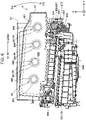
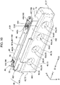
- FIG. 9 is an exploded perspective view of the first-type cartridge 4A.
- FIG. 10 is a first perspective view of the first-type cartridge 4A.
- FIG. 11 is a bottom view of the first-type cartridge 4A.
- FIG. 12 is a second perspective view of the first-type cartridge 4A.
- FIG. 13 is a side view of the first-type cartridge 4A.
- FIG. 14 is a sectional view along line XIV-XIV in FIG. 13 .
- FIG. 15 is a perspective view of the first-type cartridge 4A illustrated in FIG. 14 .
- FIGS. 9 and 10 omit illustration of a film 200 that closes an insertion opening 446.
- the width of the casing 401 of the first-type cartridge 4A which will be described later, is greater than the width of the casing 401 of the second-type cartridge 4B, and the capacities of the casings 401 thus differ from each other. Since the other configurations including an adaptor 402 and the film 200 are the same in the first-type cartridge 4A and the second-type cartridge 4B, description of details of the configuration of the cartridge 4 will be given below with respect to the first-type cartridge 4A. Note that the first-type cartridge 4A is also simply referred to below as the cartridge 4.
- the X direction, the Y direction, and the Z direction are indicated in accordance with the insertion completed state in which insertion of the cartridge 4 into the cartridge attachment section 6 is completed. That is, in the drawings illustrating the cartridge 4, the X direction, the Y direction, and the Z direction are indicated in accordance with a state before the supply section coupling process, in which the supporting member 610 is rotationally moved.
- the outer shape of the cartridge 4 is an approximately rectangular parallelepiped.
- a direction extending in the -Y direction corresponding to the inserting direction D1, in which the cartridge 4 is inserted into the cartridge attachment section 6, is a long-side direction
- the X direction is a short-side direction corresponding to the width direction
- the Z direction is a height direction.
- the cartridge 4 has the largest dimension in the long-side direction and has the smallest dimension in the short-side direction.
- the cartridge 4 includes a cartridge main body 41 and a circuit substrate 50 attached to the cartridge main body 41 and illustrated in FIG. 11 .
- the cartridge main body 41 is constituted by two members as illustrated in FIG. 9 .
- the cartridge main body 41 includes the casing 401, the adaptor 402 fit to the casing 401 to be attached thereto, and the liquid supply section 442 attached to the casing 401.
- the cartridge main body 41 may be an integrated component.
- Each of the casing 401 and the adaptor 402 is molded by, for example, injection molding of a synthetic resin, such as polypropylene.
- the casing 401 and the adaptor 402 may be formed of the same material or different materials.
- the cartridge main body 41 includes a front wall 42, a rear wall 47, a top wall 43, a bottom wall 44, a first main body side wall 45, a second main body side wall 46, and a corner section 89 illustrated in FIG. 10 .
- the walls 42, 43, 44, 45, 46, and 47 are also referred to as surfaces 42, 43, 44, 45, 46, and 47, respectively.
- the front wall 42 and the rear wall 47 face each other in the Y direction extending in the inserting direction D1.
- the top wall 43 and the bottom wall 44 face each other in the Z direction.
- the Z direction is parallel to a central axis CA2 of the liquid supply section 442.
- the first main body side wall 45 and the second main body side wall 46 face each other in the X direction.
- the front wall 42 is positioned on a side in the inserting direction D1, in which the cartridge 4 is inserted into the cartridge attachment section 6. That is, the front wall 42 forms an insertion tip end surface on the -Y direction side, which corresponds to the inserting direction D1 side.
- the rear wall 47 forms a surface on a side in the +Y direction, which corresponds to the detaching direction D4.
- the top wall 43 is positioned on the +Z direction side and intersects the front wall 42 and the rear wall 47.
- the bottom wall 44 is positioned on the -Z direction side, which corresponds to the lower side in the direction of gravity, in the attached state. The bottom wall 44 intersects the front wall 42 and the rear wall 47.
- the insertion opening 446 into which the liquid introducing section 642 is inserted is formed in the bottom wall 44.
- the insertion opening 446 and the liquid supply section 442 are positioned so as to overlap each other when the cartridge 4 is viewed from the bottom wall 44 side.
- the liquid supply section 442 is arranged such that the central axis CA2 of the liquid supply section 442 passes through the insertion opening 446.
- the first main body side wall 45 is positioned on the -X direction side
- the second main body side wall 46 is positioned on the +X direction side.
- Each of the first main body side wall 45 and the second main body side wall 46 intersects the front wall 42, the rear wall 47, the top wall 43, and the bottom wall 44 and extends in the inserting direction D1.
- the corner section 89 is provided in a corner portion in which the front wall 42 and the bottom wall 44 intersect each other.
- the corner section 89 includes a terminal arrangement section 90 having a shape recessed inwardly. As illustrated in FIG. 11 , the circuit substrate 50 is attached to the terminal arrangement section 90.
- the liquid supply section 442 is a cylindrical member protruding from a casing bottom wall 74 of the casing 401, which faces the top wall 43.
- the liquid supply section 442 has the central axis CA2.
- the liquid supply section 442 communicates with the liquid chamber 450 in which the liquid is stored and supplies the liquid in the liquid chamber 450 to the printing apparatus 10.
- the liquid supply section 442 is coupled to the liquid introducing section 642 in the attached state and supplies the liquid in the liquid chamber 450 to the ejecting head 22 of the printing apparatus 10 via the liquid introducing section 642.
- the liquid supply section 442 includes a supply section tip end 442a corresponding to a tip end that forms an opening through which the liquid is fed out.
- a valve mechanism that opens/closes a channel through which the liquid flows is arranged in the liquid supply section 422. The valve mechanism opens when the liquid introducing section 642 is inserted into the liquid supply section 422.
- the adaptor 402 includes an adaptor front wall 82, an adaptor rear wall 87, an adaptor bottom wall 84, a first adaptor side wall 85, and a second adaptor side wall 86.
- the adaptor front wall 82 constitutes a portion of the front wall 42 and is positioned on the tip end side of the inserting direction D1 side.
- the adaptor rear wall 87 constitutes a portion of the rear wall 47 and faces the adaptor front wall 82 in the Y direction.
- the adaptor bottom wall 84 constitutes the bottom wall 44 and intersects the adaptor front wall 82 and the adaptor rear wall 87.
- the first adaptor side wall 85 intersects the adaptor bottom wall 84 and extends in the Y direction, which corresponds to the long-side direction of the adaptor 402.
- the first adaptor side wall 85 is a plate-shaped wall standing from the adaptor bottom wall 84 toward the casing 401.
- the second adaptor side wall 86 faces the first adaptor side wall 85 in the X direction, which corresponds to the short-side direction of the adaptor 402.
- the second adaptor side wall 86 intersects the adaptor bottom wall 84 and extends in the Y direction, which corresponds to the long-side direction of the adaptor 402.
- the second adaptor side wall 86 is a plate-shaped wall standing from the adaptor bottom wall 84 toward the casing 401.
- the adaptor 402 has a recessed shape in which the adaptor bottom wall 84 serves as the bottom.
- the adaptor 402 has an opening on a side facing the adaptor bottom wall 84, and the liquid supply section 442 is arranged inside the adaptor 402 via the opening.
- a portion of the adaptor 402 in which the liquid supply section 442 is arranged is referred to as a supply section arrangement section 831.
- the adaptor bottom wall 84 includes the insertion opening 446, through which the liquid introducing section 642 is inserted, at a position facing the supply section tip end 442a.
- the adaptor 402 further includes an attachment element 700 that cooperates with the cartridge attachment section 6 in at least one of the attaching process in which the cartridge 4 is attached to the cartridge attachment section 6 of the printing apparatus 10 and the attached state in which the cartridge 4 is attached to the cartridge attachment section 6.
- the attachment element 700 mechanically cooperates with the cartridge attachment section 6 when, for example, coming into contact with or engaging the cartridge attachment section 6 or inserted into the cartridge attachment section 6.
- the attachment element 700 includes a cartridge-side identifying member 430, a cartridge guided section 447, the supply section positioning section 448, the cartridge engagement section 497, and the circuit substrate 50 illustrated in FIG. 11 .
- the cartridge-side identifying member 430 illustrated in FIG. 10 is constituted by a rib.
- the pattern shape of the cartridge-side identifying member 430 is determined in accordance with the number of ribs and positions of the ribs.
- the pattern shape differs in accordance with the type of the cartridge 4, that is, the color of the stored liquid.
- the cartridge guided section 447 extends in the inserting direction D1.
- the cartridge guided section 447 is indicated by single hatching in FIGS. 10 and 11 .
- the cartridge guided section 447 extends in the inserting direction D1 from a portion in which the corner section 89 is positioned to a portion in which the insertion opening 446 is positioned.
- a first cartridge guided section 447a is positioned on one side with respect to the insertion opening 446, and a second cartridge guided section 447b is positioned on the other side with respect to the insertion opening 446.
- the cartridge guided section 447 is guided in the inserting direction D1 by the apparatus guiding section 602 of the cartridge attachment section 6.
- the cartridge guided section 447 is formed of a step in each of the first adaptor side wall 85 and the second adaptor side wall 86.
- the cartridge guided section 447 is a surface facing the -Z direction.
- the cartridge guided section 447 formed in the first adaptor side wall 85 is also referred to as the first cartridge guided section 447a
- the cartridge guided section 447 formed in the second adaptor side wall 86 is also referred to as the second cartridge guided section 447b.
- the supply section positioning section 448 illustrated in FIG. 10 receives the apparatus-side supply section positioning section 644 in the attaching process to thereby position the liquid supply section 442 with respect to the liquid introducing section 642.
- the supply section positioning section 448 receives the apparatus-side supply section positioning section 644 and regulates movement of the supply section positioning section 448 in a direction intersecting the coupling direction D2 to thereby position the liquid supply section 442 with respect to the liquid introducing section 642.
- the supply section positioning section 448 is formed in the bottom wall 44 and is a recessed portion depressed from the outer surface of the bottom wall 44.
- the supply section positioning section 448 is positioned in a portion of the bottom wall 44 between the insertion opening 446 and the end to which the adaptor rear wall 87 is coupled. Note that, in other embodiments, the supply section positioning section 448 may be a hole passing through the bottom wall 44.
- the cartridge engagement section 497 is provided in the rear wall 47, specifically, the adaptor rear wall 87.
- the cartridge engagement section 497 is a recessed portion depressed from the outer surface of the adaptor rear wall 87.
- the cartridge engagement section 497 is formed in a portion of the adaptor rear wall 87 in the vicinity of the end intersecting the adaptor bottom wall 84.
- the circuit substrate 50 is arranged in the terminal arrangement section 90 provided in the adaptor 402.
- the circuit substrate 50 includes a cartridge-side terminal 521 that comes into contact with an apparatus-side terminal 721 in the attached state.
- the film 200 is attached to the adaptor 402 in a removable manner in a state of covering the insertion opening 446.
- the film 200 is peeled off from the cartridge 4 by a user before the cartridge 4 is attached to the cartridge attachment section 6.
- the film 200 is formed of a synthetic resin, such as polyethylene terephthalate or polypropylene.
- the casing 401 is a casing that demarcates the liquid chamber 450 used for storing the liquid and that is hollow. As illustrated in FIGS. 10 and 12 , the casing 401 includes a casing top wall 73, the casing bottom wall 74, and four casing side walls 72, 75, 76, and 77. The walls 72 to 77 form the contour of the casing 401.
- the casing bottom wall 74 illustrated in FIG. 10 is a wall to which the liquid supply section 442 is coupled.
- the casing bottom wall 74 forms the bottom surface of the casing 401 in the attachment completed state in which the cartridge 4 is attached to the cartridge attachment section 6.
- the casing top wall 73 illustrated in FIG. 12 constitutes the top wall 43 of the cartridge main body 41.
- the casing top wall 73 faces the casing bottom wall 74 in a central axis direction extending along the central axis CA2.
- the four casing side walls 72, 75, 76, and 77 are walls that couple the casing bottom wall 74 and the casing top wall 73.
- the four casing side walls 72, 75, 76, and 77 are the casing front wall 72, the first casing side wall 75, the second casing side wall 76, and the casing rear wall 77.
- the casing front wall 72 constitutes a portion of the front wall 42 and is positioned on the tip end side in the inserting direction D1.
- the casing rear wall 77 constitutes a portion of the rear wall 47 of the cartridge main body 41.
- the casing rear wall 77 faces the casing front wall 72 in the Y direction extending in the inserting direction D1.
- the first casing side wall 75 which corresponds to a first side wall, constitutes a portion of the first main body side wall 45.
- the first casing side wall 75 couples the casing front wall 72 and the casing rear wall 77.
- the first casing side wall 75 is a side wall on one side in the width direction of the casing 401.
- the second casing side wall 76 which corresponds to a second side wall, constitutes a portion of the second main body side wall 46.
- the second casing side wall 76 faces the first casing side wall 75 in the X direction, which corresponds to the width direction of the casing 401.
- the second casing side wall 76 is a side wall on the other side in the width direction of the casing 401.
- the second casing side wall 76 couples the casing front wall 72 and the casing rear wall 77.
- the external sizes of the first casing side wall 75 and the second casing side wall 76 are larger than the external sizes of the casing front wall 72 and the casing rear wall 77.
- the external sizes of the first casing side wall 75 and the second casing side wall 76 are the same and the largest of the walls 72, 73, 74, 75, 76, and 77 that form the casing 401.
- the casing 401 includes a concave/convex portion 99.
- the concave/convex portion 99 includes a first concave/convex portion 91 formed in the first casing side wall 75, which corresponds to the first side wall, as illustrated in FIG. 10 and a second concave/convex portion 92 formed in the second casing side wall 76, which corresponds to the second side wall, as illustrated in FIG. 12 .
- first concave/convex portions 91 are provided.
- the four first concave/convex portions 91 are formed at predetermined intervals so as to be arranged side by side in the Y direction extending in the inserting direction D1.
- four second concave/convex portions 92 are provided.
- the four second concave/convex portions 92 are formed at predetermined intervals so as to be arranged side by side in the Y direction extending in the inserting direction D1.
- the four first concave/convex portions 91 and the four second concave/convex portions 92 are formed such that each of the first concave/convex portions 91 faces a corresponding one of the second concave/convex portions 92 in the X direction, which corresponds to the width direction of the casing 401.
- the concave/convex portion 99 includes a concave portion 93 recessed from an outer surface 401fa of the casing 401 toward the inner side which corresponds to the liquid chamber 450 side and a convex portion 94 formed of the concave portion 93 and protruding from an inner surface 401fb of the casing 401 toward the liquid chamber 450 side.
- the concave portion 93 of the first concave/convex portion 91 illustrated in FIG. 10 is also referred to as a first concave portion 93a
- the convex portion 94 of the first concave/convex portion 91 illustrated in FIG. 14 is also referred to as a first convex portion 94a.
- the concave portion 93 of the second concave/convex portion 92 illustrated in FIG. 12 is also referred to as a second concave portion 93b
- the convex portion 94 of the second concave/convex portion 92 illustrated in FIG. 14 is also referred to as a second convex portion 94b.
- a sectional shape of the concave portion 93 which is orthogonal to the X direction in which the concave portion 93 is recessed, is round.
- a sectional shape of the convex portion 94 which is orthogonal to the X direction in which the convex portion 94 protrudes, is round. Accordingly, in the attachment completed state in which the cartridge 4 is attached to the cartridge attachment section 6, an outer peripheral surface 991 of the convex portion 94 has no horizontal surface. That is, as illustrated in FIG.
- an upper surface 998 of the outer peripheral surface 991 of the convex portion 94 which is positioned in an upper portion, is an arc-shaped surface and is inclined with respect to the horizontal direction. That is, the upper surface 998 is inclined with respect to the horizontal direction so as to extend gradually downward from the uppermost apex portion.
- a first tip end 98a which is a tip end of the first convex portion 94a in the protruding direction
- a second tip end 98b which is a tip end of the second convex portion 94b in the protruding direction
- Each of the first tip end 98a and the second tip end 98b is a round planar surface.
- the convex portion 94 of the concave/convex portion 99 is disposed at a position deviated from the central axis CA2 of the liquid supply section 442 as illustrated in FIG. 14 .
- the convex portion 94 of the concave/convex portion 99 is disposed in a second region Rg2 different from a first region Rg1, in which the liquid supply section 442 is positioned.
- the concave/convex portion 99 is formed by, for example, the following method. First, the first casing side wall 75 and the second casing side wall 76 are heated and softened to be in a starch-syrup-like state, and a column-shaped pin is then pressed against the outer surface 401fa of each of the first casing side wall 75 and the second casing side wall 76 in an inward direction. After the pin is pressed until the tip ends of the first convex portion 94a and the second convex portion 94b, which are formed by being pressed by the pin, come into contact with each other, the casing 401 is cooled, for example, naturally. The first concave/convex portion 91 and the second concave/convex portion 92 are thus formed.
- the casing 401 that is hollow includes the concave/convex portion 99 as illustrated in FIGS. 10 and 12 , it is possible to improve rigidity of the casing 401 without adding a component separate from the casing 401. This makes it possible to reduce possible damage of the casing 401 even in an instance in which an impact is applied to the cartridge 4 when, for example, the cartridge 4 falls down. Moreover, even when the internal pressure of the liquid chamber 450 is lowered, it is possible to reduce possible deformation of the casing 401.
- the rigidity of the casing 401 is improved by using the concave/convex portion 99, it is possible to ensure desired rigidity regardless of the amount of liquid stored in the liquid chamber 450, thus making it possible to flexibly change the amount of liquid to be stored in the liquid chamber 450.
- the first tip end 98a of the first convex portion 94a and the second tip end 98b of the second convex portion 94b are bonded to each other as illustrated in FIG. 14 , thus making it possible to further improve the rigidity of the casing 401.
- the concave/convex portion 99 includes the concave portion 93 recessed from the outer surface 401fa of the casing 401 toward the inner side which corresponds to the liquid chamber 450 side and the convex portion 94 formed of the concave portion 93 and protruding from the inner surface 401fb of the casing 401 toward the liquid chamber 450 side as illustrated in FIG. 15 . It is thereby possible to easily form the concave portion 93 and the convex portion 94 of the concave/convex portion 99.
- the concave/convex portion 99 is disposed in the second region Rg2 different from the first region Rg1, in which the liquid supply section 442 is positioned, as illustrated in FIG. 14 .
- the cartridge 4 is arranged to have a pouring posture in which the supply section tip end 442a of the liquid supply section 442, which is illustrated in FIG. 10 , faces upward, a stick-shaped liquid pouring tube which is a jig is inserted into the liquid chamber 450 from the liquid supply section 442.
- the liquid pouring tube is inserted into the liquid chamber 450 such that the tip end of the liquid pouring tube is positioned in the vicinity of the top wall 43 to suppress generation of bubbles in the liquid chamber 450 in a liquid pouring process, and the liquid is then poured.
- the liquid is poured while the tip end of the liquid pouring tube is moved to the bottom wall 44 side, that is, the upper side of the cartridge 4 having the pouring posture, in accordance with the rising liquid surface in the liquid chamber 450.
- the upper surface 998 of the outer peripheral surface 991 of the convex portion 94 is an arc-shaped surface and is inclined with respect to the horizontal direction as illustrated in FIG. 6 . Accordingly, the upper surface 998 of the convex portion 94 has no horizontal surface in the attachment completed state, thus making it possible to suppress the liquid in the liquid chamber 450 remaining on the upper surface 998 of the convex portion 94. It is thereby possible to reduce an amount of liquid to remain in the liquid chamber 450.
- the convex portion 94 has a truncated cone shape, and a sectional shape of the convex portion 94, which is orthogonal to the protruding direction of the convex portion 94, is round, as illustrated in FIG. 15 . It is therefore possible to easily form the convex portion 94 such that, in the attachment completed state, the upper surface 998 of the outer peripheral surface 991 of the convex portion 94 has an arc-shaped surface.
- the concave/convex portion 99 is formed in the first casing side wall 75 and the second casing side wall 76 in the aforementioned embodiment but may be formed in a different wall of the casing 401.
- the concave/convex portion 99 may be formed in the casing front wall 72 and the casing rear wall 77.
- the casing front wall 72 functions as the first side wall
- the casing rear wall 77 functions as the second side wall.
- the concave/convex portion 99 may be formed in the casing top wall 73 and the casing bottom wall 74.
- the concave/convex portion 99 is not necessarily formed in two walls of the casing 401 which face each other.
- the concave/convex portion 99 may be formed in at least one of the casing top wall 73, the first casing side wall 75, the second casing side wall 76, the casing front wall 72, the casing rear wall 77, and the casing bottom wall 74.
- the concave portion 93 and the convex portion 94 of the concave/convex portion 99 may be formed at different positions.
- the shape of the convex portion 94 is not limited to the truncated cone shape.
- the convex portion 94 may have, for example, a rectangular parallelepiped shape or a column shape.
- the disclosure is not limited to an ink jet printer and a cartridge used in an ink jet printer and may be applied to a cartridge attached to any printing apparatus that ejects liquid other than ink.
- the disclosure may be applied to various printing apparatuses as follows and cartridges therefor:
- liquid droplets refers to a state of liquid ejected from the printing apparatus, and examples thereof include a granular shape, a tear shape, and a thread shape in a trailing shape.
- liquid here refers to any material that is able to be ejected by the printing apparatus.
- liquid may be any material as long as it is a material in a state in which a substance is in a liquid phase, and examples thereof include a liquid state material having high or low viscosity and a liquid state material such as sol, gel water, other inorganic solvents, organic solvent, solution, liquid resin, and liquid metal.
- liquid further include, in addition to liquid as one state of a substance, materials in which particles of a functional material having solids such as pigments and metal particles are dissolved, dispersed, or mixed in a solvent.
- representative examples of liquid include ink as described in the embodiment described above, liquid crystal, and the like.
- the ink include various liquid compositions such as typical water-based ink, oilbased ink, gel ink, and hot-melt ink.
- the disclosure is able to be implemented in an aspect of a manufacturing method of a cartridge, a printing system including a cartridge and a printing apparatus, and the like in addition to the above-described aspects.
Landscapes
- Ink Jet (AREA)
Applications Claiming Priority (2)
| Application Number | Priority Date | Filing Date | Title |
|---|---|---|---|
| JP2021045568A JP2022144519A (ja) | 2021-03-19 | 2021-03-19 | カートリッジ |
| JP2021113362A JP2023009790A (ja) | 2021-07-08 | 2021-07-08 | カートリッジ |
Publications (2)
| Publication Number | Publication Date |
|---|---|
| EP4063130A1 true EP4063130A1 (fr) | 2022-09-28 |
| EP4063130B1 EP4063130B1 (fr) | 2023-08-09 |
Family
ID=80786814
Family Applications (1)
| Application Number | Title | Priority Date | Filing Date |
|---|---|---|---|
| EP22162792.0A Active EP4063130B1 (fr) | 2021-03-19 | 2022-03-17 | Cartouche |
Country Status (4)
| Country | Link |
|---|---|
| US (1) | US11807015B2 (fr) |
| EP (1) | EP4063130B1 (fr) |
| CN (1) | CN115107373B (fr) |
| ES (1) | ES2963742T3 (fr) |
Families Citing this family (2)
| Publication number | Priority date | Publication date | Assignee | Title |
|---|---|---|---|---|
| JP1708597S (fr) * | 2021-08-11 | 2022-03-01 | ||
| JP1708596S (fr) * | 2021-08-11 | 2022-03-01 |
Citations (10)
| Publication number | Priority date | Publication date | Assignee | Title |
|---|---|---|---|---|
| US20080165232A1 (en) * | 2007-01-10 | 2008-07-10 | Kenneth Yuen | Ink cartridge |
| US20080284810A1 (en) * | 2006-11-06 | 2008-11-20 | Kazutoshi Shimizu | Liquid container, container holder and liquid consuming apparatus |
| WO2012086171A1 (fr) | 2010-12-22 | 2012-06-28 | セイコーエプソン株式会社 | Cartouche |
| EP2727733A1 (fr) * | 2012-01-13 | 2014-05-07 | Seiko Epson Corporation | Cartouche, système d'alimentation d'un matériau d'impression, dispositif d'impression, récipient de stockage de liquide, système d'impression structure de connexion au terminal |
| US20140253646A1 (en) * | 2013-03-07 | 2014-09-11 | Seiko Epson Corporation | Liquid-accommodating-body accommodating receptacle, liquid supply apparatus, and liquid ejecting apparatus |
| US20170120613A1 (en) * | 2015-10-30 | 2017-05-04 | Canon Kabushiki Kaisha | Liquid ejecting device and head |
| US20180281435A1 (en) * | 2017-03-28 | 2018-10-04 | Brother Kogyo Kabushiki Kaisha | Liquid container and cartridge |
| EP3459744A1 (fr) * | 2017-09-20 | 2019-03-27 | Seiko Epson Corporation | Cartouche |
| JP2021045568A (ja) | 2020-11-27 | 2021-03-25 | 株式会社東芝 | システム及び方法 |
| JP2021113362A (ja) | 2019-09-27 | 2021-08-05 | マクセルホールディングス株式会社 | 蒸着マスク |
Family Cites Families (18)
| Publication number | Priority date | Publication date | Assignee | Title |
|---|---|---|---|---|
| US3733915A (en) | 1970-02-19 | 1973-05-22 | Trico Products Corp | Concealed windshield wiper system |
| JP3133906B2 (ja) * | 1993-08-19 | 2001-02-13 | キヤノン株式会社 | インクタンクカートリッジ |
| CN2421159Y (zh) * | 2000-04-03 | 2001-02-28 | 林超铭 | 喷墨打印机的墨水匣 |
| CN2451335Y (zh) * | 2000-11-08 | 2001-10-03 | 北京高斯达喷墨墨水有限公司 | 一种适用于喷墨打印机的墨盒 |
| JP2007283557A (ja) | 2006-04-13 | 2007-11-01 | Seiko Epson Corp | 液体収容体 |
| JP4321562B2 (ja) * | 2006-08-08 | 2009-08-26 | セイコーエプソン株式会社 | 液体収容容器 |
| JP5454398B2 (ja) * | 2010-07-15 | 2014-03-26 | セイコーエプソン株式会社 | 液体収容容器、タンクユニット、および、液体噴射システム |
| JP5720148B2 (ja) | 2010-09-03 | 2015-05-20 | セイコーエプソン株式会社 | 印刷材カートリッジ、及び、印刷材供給システム |
| JP2013049168A (ja) * | 2011-08-30 | 2013-03-14 | Brother Industries Ltd | 印刷流体カートリッジ及び記録装置 |
| JP5998471B2 (ja) | 2011-12-20 | 2016-09-28 | セイコーエプソン株式会社 | アダプター |
| CN202428819U (zh) * | 2012-01-05 | 2012-09-12 | 深圳市打印王耗材有限公司 | 组装式喷墨打印机墨盒 |
| TWI636893B (zh) | 2012-01-12 | 2018-10-01 | 精工愛普生股份有限公司 | 油墨卡匣、配接器及卡匣 |
| WO2014024458A1 (fr) | 2012-08-10 | 2014-02-13 | セイコーエプソン株式会社 | Contenant de liquide, dispositif de consommation de liquide, système d'alimentation en liquide, et unité de contenant de liquide |
| JP6142571B2 (ja) | 2013-02-28 | 2017-06-07 | セイコーエプソン株式会社 | カートリッジ、液体供給システム、液体吐出装置 |
| US9481180B2 (en) * | 2013-03-01 | 2016-11-01 | Seiko Epson Corporation | Liquid container, liquid container unit, liquid ejecting system, and liquid ejecting apparatus |
| JP3185521U (ja) * | 2013-05-23 | 2013-08-22 | エステー産業株式会社 | インクカートリッジ |
| JP6665649B2 (ja) | 2016-04-15 | 2020-03-13 | セイコーエプソン株式会社 | カートリッジ |
| CN210259168U (zh) * | 2019-08-12 | 2020-04-07 | 苏州鹏瑞纳米科技有限公司 | 一种用于气雾剂灌装的塑料瓶 |
-
2022
- 2022-03-16 CN CN202210277189.3A patent/CN115107373B/zh active Active
- 2022-03-17 EP EP22162792.0A patent/EP4063130B1/fr active Active
- 2022-03-17 ES ES22162792T patent/ES2963742T3/es active Active
- 2022-03-18 US US17/698,307 patent/US11807015B2/en active Active
Patent Citations (10)
| Publication number | Priority date | Publication date | Assignee | Title |
|---|---|---|---|---|
| US20080284810A1 (en) * | 2006-11-06 | 2008-11-20 | Kazutoshi Shimizu | Liquid container, container holder and liquid consuming apparatus |
| US20080165232A1 (en) * | 2007-01-10 | 2008-07-10 | Kenneth Yuen | Ink cartridge |
| WO2012086171A1 (fr) | 2010-12-22 | 2012-06-28 | セイコーエプソン株式会社 | Cartouche |
| EP2727733A1 (fr) * | 2012-01-13 | 2014-05-07 | Seiko Epson Corporation | Cartouche, système d'alimentation d'un matériau d'impression, dispositif d'impression, récipient de stockage de liquide, système d'impression structure de connexion au terminal |
| US20140253646A1 (en) * | 2013-03-07 | 2014-09-11 | Seiko Epson Corporation | Liquid-accommodating-body accommodating receptacle, liquid supply apparatus, and liquid ejecting apparatus |
| US20170120613A1 (en) * | 2015-10-30 | 2017-05-04 | Canon Kabushiki Kaisha | Liquid ejecting device and head |
| US20180281435A1 (en) * | 2017-03-28 | 2018-10-04 | Brother Kogyo Kabushiki Kaisha | Liquid container and cartridge |
| EP3459744A1 (fr) * | 2017-09-20 | 2019-03-27 | Seiko Epson Corporation | Cartouche |
| JP2021113362A (ja) | 2019-09-27 | 2021-08-05 | マクセルホールディングス株式会社 | 蒸着マスク |
| JP2021045568A (ja) | 2020-11-27 | 2021-03-25 | 株式会社東芝 | システム及び方法 |
Also Published As
| Publication number | Publication date |
|---|---|
| US20220297437A1 (en) | 2022-09-22 |
| US11807015B2 (en) | 2023-11-07 |
| CN115107373B (zh) | 2023-08-22 |
| CN115107373A (zh) | 2022-09-27 |
| EP4063130B1 (fr) | 2023-08-09 |
| ES2963742T3 (es) | 2024-04-01 |
Similar Documents
| Publication | Publication Date | Title |
|---|---|---|
| EP2907666B1 (fr) | Unité de réservoir et système d'éjection de liquide doté de celle-ci | |
| US10618297B2 (en) | Tank and liquid ejection device | |
| EP4063130B1 (fr) | Cartouche | |
| JP2016187872A (ja) | カートリッジおよび液体噴射装置 | |
| US11673398B2 (en) | Cartridge, printing system, and printing device | |
| WO2017115582A1 (fr) | Unité d'alimentation en liquide | |
| US11691427B2 (en) | Cartridge, printing device, and printing system | |
| KR20220133111A (ko) | 카트리지 | |
| WO2019098287A1 (fr) | Cartouche et dispositif d'éjection de liquide | |
| CN115107372A (zh) | 容器 | |
| JP5533560B2 (ja) | 液体消費装置 | |
| JP2017056686A (ja) | 端子接続部およびカートリッジ | |
| US20180281433A1 (en) | Liquid supply unit and liquid jetting device | |
| US9636917B2 (en) | Liquid supply unit | |
| JP6511910B2 (ja) | カートリッジ、及び、液体噴射システム | |
| EP4309902A1 (fr) | Cartouche | |
| JP2023009790A (ja) | カートリッジ | |
| US20230398783A1 (en) | Cartridge and printing system | |
| WO2022065203A1 (fr) | Cartouche, système d'impression et dispositif d'impression | |
| JP2022191134A (ja) | カートリッジ | |
| WO2022264958A1 (fr) | Cartouche et système d'impression | |
| CN117042972A (zh) | 盒 | |
| JP2023016351A (ja) | カートリッジおよび異種カートリッジ |
Legal Events
| Date | Code | Title | Description |
|---|---|---|---|
| PUAI | Public reference made under article 153(3) epc to a published international application that has entered the european phase |
Free format text: ORIGINAL CODE: 0009012 |
|
| STAA | Information on the status of an ep patent application or granted ep patent |
Free format text: STATUS: THE APPLICATION HAS BEEN PUBLISHED |
|
| AK | Designated contracting states |
Kind code of ref document: A1 Designated state(s): AL AT BE BG CH CY CZ DE DK EE ES FI FR GB GR HR HU IE IS IT LI LT LU LV MC MK MT NL NO PL PT RO RS SE SI SK SM TR |
|
| STAA | Information on the status of an ep patent application or granted ep patent |
Free format text: STATUS: REQUEST FOR EXAMINATION WAS MADE |
|
| 17P | Request for examination filed |
Effective date: 20221124 |
|
| RBV | Designated contracting states (corrected) |
Designated state(s): AL AT BE BG CH CY CZ DE DK EE ES FI FR GB GR HR HU IE IS IT LI LT LU LV MC MK MT NL NO PL PT RO RS SE SI SK SM TR |
|
| GRAP | Despatch of communication of intention to grant a patent |
Free format text: ORIGINAL CODE: EPIDOSNIGR1 |
|
| STAA | Information on the status of an ep patent application or granted ep patent |
Free format text: STATUS: GRANT OF PATENT IS INTENDED |
|
| INTG | Intention to grant announced |
Effective date: 20230425 |
|
| GRAS | Grant fee paid |
Free format text: ORIGINAL CODE: EPIDOSNIGR3 |
|
| GRAA | (expected) grant |
Free format text: ORIGINAL CODE: 0009210 |
|
| STAA | Information on the status of an ep patent application or granted ep patent |
Free format text: STATUS: THE PATENT HAS BEEN GRANTED |
|
| AK | Designated contracting states |
Kind code of ref document: B1 Designated state(s): AL AT BE BG CH CY CZ DE DK EE ES FI FR GB GR HR HU IE IS IT LI LT LU LV MC MK MT NL NO PL PT RO RS SE SI SK SM TR |
|
| REG | Reference to a national code |
Ref country code: GB Ref legal event code: FG4D |
|
| REG | Reference to a national code |
Ref country code: CH Ref legal event code: EP |
|
| REG | Reference to a national code |
Ref country code: DE Ref legal event code: R096 Ref document number: 602022000306 Country of ref document: DE |
|
| REG | Reference to a national code |
Ref country code: IE Ref legal event code: FG4D |
|
| REG | Reference to a national code |
Ref country code: LT Ref legal event code: MG9D |
|
| REG | Reference to a national code |
Ref country code: NL Ref legal event code: MP Effective date: 20230809 |
|
| REG | Reference to a national code |
Ref country code: AT Ref legal event code: MK05 Ref document number: 1597066 Country of ref document: AT Kind code of ref document: T Effective date: 20230809 |
|
| PG25 | Lapsed in a contracting state [announced via postgrant information from national office to epo] |
Ref country code: GR Free format text: LAPSE BECAUSE OF FAILURE TO SUBMIT A TRANSLATION OF THE DESCRIPTION OR TO PAY THE FEE WITHIN THE PRESCRIBED TIME-LIMIT Effective date: 20231110 |
|
| PG25 | Lapsed in a contracting state [announced via postgrant information from national office to epo] |
Ref country code: IS Free format text: LAPSE BECAUSE OF FAILURE TO SUBMIT A TRANSLATION OF THE DESCRIPTION OR TO PAY THE FEE WITHIN THE PRESCRIBED TIME-LIMIT Effective date: 20231209 |
|
| PG25 | Lapsed in a contracting state [announced via postgrant information from national office to epo] |
Ref country code: SE Free format text: LAPSE BECAUSE OF FAILURE TO SUBMIT A TRANSLATION OF THE DESCRIPTION OR TO PAY THE FEE WITHIN THE PRESCRIBED TIME-LIMIT Effective date: 20230809 Ref country code: RS Free format text: LAPSE BECAUSE OF FAILURE TO SUBMIT A TRANSLATION OF THE DESCRIPTION OR TO PAY THE FEE WITHIN THE PRESCRIBED TIME-LIMIT Effective date: 20230809 Ref country code: PT Free format text: LAPSE BECAUSE OF FAILURE TO SUBMIT A TRANSLATION OF THE DESCRIPTION OR TO PAY THE FEE WITHIN THE PRESCRIBED TIME-LIMIT Effective date: 20231211 Ref country code: NO Free format text: LAPSE BECAUSE OF FAILURE TO SUBMIT A TRANSLATION OF THE DESCRIPTION OR TO PAY THE FEE WITHIN THE PRESCRIBED TIME-LIMIT Effective date: 20231109 Ref country code: NL Free format text: LAPSE BECAUSE OF FAILURE TO SUBMIT A TRANSLATION OF THE DESCRIPTION OR TO PAY THE FEE WITHIN THE PRESCRIBED TIME-LIMIT Effective date: 20230809 Ref country code: LV Free format text: LAPSE BECAUSE OF FAILURE TO SUBMIT A TRANSLATION OF THE DESCRIPTION OR TO PAY THE FEE WITHIN THE PRESCRIBED TIME-LIMIT Effective date: 20230809 Ref country code: LT Free format text: LAPSE BECAUSE OF FAILURE TO SUBMIT A TRANSLATION OF THE DESCRIPTION OR TO PAY THE FEE WITHIN THE PRESCRIBED TIME-LIMIT Effective date: 20230809 Ref country code: IS Free format text: LAPSE BECAUSE OF FAILURE TO SUBMIT A TRANSLATION OF THE DESCRIPTION OR TO PAY THE FEE WITHIN THE PRESCRIBED TIME-LIMIT Effective date: 20231209 Ref country code: HR Free format text: LAPSE BECAUSE OF FAILURE TO SUBMIT A TRANSLATION OF THE DESCRIPTION OR TO PAY THE FEE WITHIN THE PRESCRIBED TIME-LIMIT Effective date: 20230809 Ref country code: GR Free format text: LAPSE BECAUSE OF FAILURE TO SUBMIT A TRANSLATION OF THE DESCRIPTION OR TO PAY THE FEE WITHIN THE PRESCRIBED TIME-LIMIT Effective date: 20231110 Ref country code: FI Free format text: LAPSE BECAUSE OF FAILURE TO SUBMIT A TRANSLATION OF THE DESCRIPTION OR TO PAY THE FEE WITHIN THE PRESCRIBED TIME-LIMIT Effective date: 20230809 Ref country code: AT Free format text: LAPSE BECAUSE OF FAILURE TO SUBMIT A TRANSLATION OF THE DESCRIPTION OR TO PAY THE FEE WITHIN THE PRESCRIBED TIME-LIMIT Effective date: 20230809 |
|
| PG25 | Lapsed in a contracting state [announced via postgrant information from national office to epo] |
Ref country code: PL Free format text: LAPSE BECAUSE OF FAILURE TO SUBMIT A TRANSLATION OF THE DESCRIPTION OR TO PAY THE FEE WITHIN THE PRESCRIBED TIME-LIMIT Effective date: 20230809 |
|
| REG | Reference to a national code |
Ref country code: ES Ref legal event code: FG2A Ref document number: 2963742 Country of ref document: ES Kind code of ref document: T3 Effective date: 20240401 |
|
| PG25 | Lapsed in a contracting state [announced via postgrant information from national office to epo] |
Ref country code: SM Free format text: LAPSE BECAUSE OF FAILURE TO SUBMIT A TRANSLATION OF THE DESCRIPTION OR TO PAY THE FEE WITHIN THE PRESCRIBED TIME-LIMIT Effective date: 20230809 Ref country code: RO Free format text: LAPSE BECAUSE OF FAILURE TO SUBMIT A TRANSLATION OF THE DESCRIPTION OR TO PAY THE FEE WITHIN THE PRESCRIBED TIME-LIMIT Effective date: 20230809 Ref country code: EE Free format text: LAPSE BECAUSE OF FAILURE TO SUBMIT A TRANSLATION OF THE DESCRIPTION OR TO PAY THE FEE WITHIN THE PRESCRIBED TIME-LIMIT Effective date: 20230809 Ref country code: DK Free format text: LAPSE BECAUSE OF FAILURE TO SUBMIT A TRANSLATION OF THE DESCRIPTION OR TO PAY THE FEE WITHIN THE PRESCRIBED TIME-LIMIT Effective date: 20230809 Ref country code: CZ Free format text: LAPSE BECAUSE OF FAILURE TO SUBMIT A TRANSLATION OF THE DESCRIPTION OR TO PAY THE FEE WITHIN THE PRESCRIBED TIME-LIMIT Effective date: 20230809 Ref country code: SK Free format text: LAPSE BECAUSE OF FAILURE TO SUBMIT A TRANSLATION OF THE DESCRIPTION OR TO PAY THE FEE WITHIN THE PRESCRIBED TIME-LIMIT Effective date: 20230809 |
|
| PGFP | Annual fee paid to national office [announced via postgrant information from national office to epo] |
Ref country code: DE Payment date: 20240328 Year of fee payment: 3 |