WO2012053280A1 - 流体式動力伝達装置のロックアップ装置 - Google Patents
流体式動力伝達装置のロックアップ装置 Download PDFInfo
- Publication number
- WO2012053280A1 WO2012053280A1 PCT/JP2011/068918 JP2011068918W WO2012053280A1 WO 2012053280 A1 WO2012053280 A1 WO 2012053280A1 JP 2011068918 W JP2011068918 W JP 2011068918W WO 2012053280 A1 WO2012053280 A1 WO 2012053280A1
- Authority
- WO
- WIPO (PCT)
- Prior art keywords
- inertia
- hysteresis torque
- output
- turbine
- power transmission
- Prior art date
- Legal status (The legal status is an assumption and is not a legal conclusion. Google has not performed a legal analysis and makes no representation as to the accuracy of the status listed.)
- Ceased
Links
Images





Classifications
-
- F—MECHANICAL ENGINEERING; LIGHTING; HEATING; WEAPONS; BLASTING
- F16—ENGINEERING ELEMENTS AND UNITS; GENERAL MEASURES FOR PRODUCING AND MAINTAINING EFFECTIVE FUNCTIONING OF MACHINES OR INSTALLATIONS; THERMAL INSULATION IN GENERAL
- F16H—GEARING
- F16H45/00—Combinations of fluid gearings for conveying rotary motion with couplings or clutches
- F16H45/02—Combinations of fluid gearings for conveying rotary motion with couplings or clutches with mechanical clutches for bridging a fluid gearing of the hydrokinetic type
-
- F—MECHANICAL ENGINEERING; LIGHTING; HEATING; WEAPONS; BLASTING
- F16—ENGINEERING ELEMENTS AND UNITS; GENERAL MEASURES FOR PRODUCING AND MAINTAINING EFFECTIVE FUNCTIONING OF MACHINES OR INSTALLATIONS; THERMAL INSULATION IN GENERAL
- F16F—SPRINGS; SHOCK-ABSORBERS; MEANS FOR DAMPING VIBRATION
- F16F15/00—Suppression of vibrations in systems; Means or arrangements for avoiding or reducing out-of-balance forces, e.g. due to motion
- F16F15/10—Suppression of vibrations in rotating systems by making use of members moving with the system
- F16F15/14—Suppression of vibrations in rotating systems by making use of members moving with the system using masses freely rotating with the system, i.e. uninvolved in transmitting driveline torque, e.g. rotative dynamic dampers
- F16F15/1407—Suppression of vibrations in rotating systems by making use of members moving with the system using masses freely rotating with the system, i.e. uninvolved in transmitting driveline torque, e.g. rotative dynamic dampers the rotation being limited with respect to the driving means
- F16F15/1414—Masses driven by elastic elements
- F16F15/1421—Metallic springs, e.g. coil or spiral springs
- F16F15/1428—Metallic springs, e.g. coil or spiral springs with a single mass
-
- F—MECHANICAL ENGINEERING; LIGHTING; HEATING; WEAPONS; BLASTING
- F16—ENGINEERING ELEMENTS AND UNITS; GENERAL MEASURES FOR PRODUCING AND MAINTAINING EFFECTIVE FUNCTIONING OF MACHINES OR INSTALLATIONS; THERMAL INSULATION IN GENERAL
- F16F—SPRINGS; SHOCK-ABSORBERS; MEANS FOR DAMPING VIBRATION
- F16F15/00—Suppression of vibrations in systems; Means or arrangements for avoiding or reducing out-of-balance forces, e.g. due to motion
- F16F15/10—Suppression of vibrations in rotating systems by making use of members moving with the system
- F16F15/12—Suppression of vibrations in rotating systems by making use of members moving with the system using elastic members or friction-damping members, e.g. between a rotating shaft and a gyratory mass mounted thereon
- F16F15/131—Suppression of vibrations in rotating systems by making use of members moving with the system using elastic members or friction-damping members, e.g. between a rotating shaft and a gyratory mass mounted thereon the rotating system comprising two or more gyratory masses
- F16F15/139—Suppression of vibrations in rotating systems by making use of members moving with the system using elastic members or friction-damping members, e.g. between a rotating shaft and a gyratory mass mounted thereon the rotating system comprising two or more gyratory masses characterised by friction-damping means
-
- F—MECHANICAL ENGINEERING; LIGHTING; HEATING; WEAPONS; BLASTING
- F16—ENGINEERING ELEMENTS AND UNITS; GENERAL MEASURES FOR PRODUCING AND MAINTAINING EFFECTIVE FUNCTIONING OF MACHINES OR INSTALLATIONS; THERMAL INSULATION IN GENERAL
- F16F—SPRINGS; SHOCK-ABSORBERS; MEANS FOR DAMPING VIBRATION
- F16F15/00—Suppression of vibrations in systems; Means or arrangements for avoiding or reducing out-of-balance forces, e.g. due to motion
- F16F15/10—Suppression of vibrations in rotating systems by making use of members moving with the system
- F16F15/14—Suppression of vibrations in rotating systems by making use of members moving with the system using masses freely rotating with the system, i.e. uninvolved in transmitting driveline torque, e.g. rotative dynamic dampers
- F16F15/1407—Suppression of vibrations in rotating systems by making use of members moving with the system using masses freely rotating with the system, i.e. uninvolved in transmitting driveline torque, e.g. rotative dynamic dampers the rotation being limited with respect to the driving means
- F16F15/145—Masses mounted with play with respect to driving means thus enabling free movement over a limited range
-
- F—MECHANICAL ENGINEERING; LIGHTING; HEATING; WEAPONS; BLASTING
- F16—ENGINEERING ELEMENTS AND UNITS; GENERAL MEASURES FOR PRODUCING AND MAINTAINING EFFECTIVE FUNCTIONING OF MACHINES OR INSTALLATIONS; THERMAL INSULATION IN GENERAL
- F16H—GEARING
- F16H41/00—Rotary fluid gearing of the hydrokinetic type
- F16H41/24—Details
- F16H2041/243—Connections between pump shell and cover shell of the turbine
-
- F—MECHANICAL ENGINEERING; LIGHTING; HEATING; WEAPONS; BLASTING
- F16—ENGINEERING ELEMENTS AND UNITS; GENERAL MEASURES FOR PRODUCING AND MAINTAINING EFFECTIVE FUNCTIONING OF MACHINES OR INSTALLATIONS; THERMAL INSULATION IN GENERAL
- F16H—GEARING
- F16H45/00—Combinations of fluid gearings for conveying rotary motion with couplings or clutches
- F16H45/02—Combinations of fluid gearings for conveying rotary motion with couplings or clutches with mechanical clutches for bridging a fluid gearing of the hydrokinetic type
- F16H2045/0205—Combinations of fluid gearings for conveying rotary motion with couplings or clutches with mechanical clutches for bridging a fluid gearing of the hydrokinetic type two chamber system, i.e. without a separated, closed chamber specially adapted for actuating a lock-up clutch
-
- F—MECHANICAL ENGINEERING; LIGHTING; HEATING; WEAPONS; BLASTING
- F16—ENGINEERING ELEMENTS AND UNITS; GENERAL MEASURES FOR PRODUCING AND MAINTAINING EFFECTIVE FUNCTIONING OF MACHINES OR INSTALLATIONS; THERMAL INSULATION IN GENERAL
- F16H—GEARING
- F16H45/00—Combinations of fluid gearings for conveying rotary motion with couplings or clutches
- F16H45/02—Combinations of fluid gearings for conveying rotary motion with couplings or clutches with mechanical clutches for bridging a fluid gearing of the hydrokinetic type
- F16H2045/0221—Combinations of fluid gearings for conveying rotary motion with couplings or clutches with mechanical clutches for bridging a fluid gearing of the hydrokinetic type with damping means
- F16H2045/0226—Combinations of fluid gearings for conveying rotary motion with couplings or clutches with mechanical clutches for bridging a fluid gearing of the hydrokinetic type with damping means comprising two or more vibration dampers
Definitions
- the present invention relates to a lockup device, and more particularly to a lockup device for a fluid power transmission device for mechanically coupling power from a front cover to a turbine of the fluid power transmission device.
- a lock-up device is provided to reduce fuel consumption.
- the lockup device is disposed in a space between the turbine and the front cover, mechanically connects the front cover and the turbine, and directly transmits torque between the two.
- the lock-up device generally has a piston and a damper mechanism.
- the piston is pressed against the front cover by the action of hydraulic pressure, and torque is transmitted from the front cover.
- the damper mechanism also includes an output-side member connected to the turbine and a plurality of torsion springs for elastically connecting the piston and the output-side member.
- the torque transmitted to the piston is transmitted to the output side member via a plurality of torsion springs, and further transmitted to the turbine.
- Patent Document 1 discloses a lock-up device that suppresses engine rotation fluctuations by attaching an inertia member to an output-side member.
- an inertia member is attached to an output member fixed to a turbine so as to be relatively rotatable.
- a torsion spring as an elastic member is provided between the output member and the inertia member.
- lock-up rotational speed In recent passenger cars, in order to improve fuel efficiency, it is required to lower the rotational speed at which the front cover and the turbine are connected (hereinafter referred to as “lock-up rotational speed”).
- the engine speed fluctuation is large in the region where the engine speed is low. Therefore, if the lockup speed is set to a low speed, the output speed fluctuation becomes larger. Therefore, by using a lock-up device having an inertia member as shown in Patent Document 1, even if the lock-up rotation speed is about 1200 rpm, for example, rotation fluctuation can be suppressed.
- the rotational speed fluctuation on the output side is minimized near 1200 rpm
- the rotational speed fluctuation becomes large near 1600 rpm.
- the characteristic of this rotational speed fluctuation that is, at which rotational speed the rotational speed fluctuation is minimized and maximized is mainly due to the magnitude of the hysteresis torque generated between the output member and the inertia member. Yes.
- An object of the present invention is to make it possible to suppress rotational fluctuations on the output side in a wide rotational speed range even when the lockup rotational speed is set to a low rotational speed.
- a lockup device for a fluid power transmission device is a device for mechanically coupling power from a front cover to a turbine of the fluid power transmission device, the piston being pressed against the front cover, and the turbine And an output side unit provided so as to be integrally rotatable.
- the output side unit includes an output member fixed to the turbine, an inertia member provided so as to be rotatable relative to the output member, an elastic member that elastically connects the inertia member and the output member in the rotation direction, and hysteresis A torque generating mechanism.
- the hysteresis torque generating mechanism is disposed between the inertia member and the output member, and generates a variable hysteresis torque between the inertia member and the output member.
- the output member and the inertia member are rotating relative to each other, and a hysteresis torque generated by a hysteresis torque generating mechanism acts between them.
- a hysteresis torque generated by a hysteresis torque generating mechanism acts between them.
- the characteristics of the rotational speed fluctuation on the output side change.
- the hysteresis torque is changed depending on the rotational speed range so that the rotational speed fluctuation on the output side becomes small in a wide rotational speed range. Therefore, even when the lockup rotational speed is set to a low rotational speed, fluctuations in rotational speed can be suppressed in a wide rotational speed region.
- the lockup device of the fluid power transmission device is the lockup device of the first aspect, wherein the hysteresis torque generating mechanism generates the first hysteresis torque in the low speed range and increases from the medium speed range to the high level. A second hysteresis torque larger than the first hysteresis torque is generated in the rotation speed range.
- Rotational speed fluctuation on the output side decreases in the low rotation speed range when the hysteresis torque between the output member and the inertia member is small, and conversely decreases in the medium rotation speed range when the hysteresis torque is large. Therefore, in the present invention, the first hysteresis torque is generated in the low rotation speed range, and the larger second hysteresis torque is generated in the medium rotation speed range to the high rotation speed range. Therefore, the rotational speed fluctuation on the output side can be suppressed in a wide rotational speed range.
- the lockup device for the fluid power transmission device wherein the output member is fixed to a driven plate to which power is input from the piston and an inner peripheral portion of the driven plate. And a hub flange fixed to the turbine.
- the inertia member has an annular inertia plate elastically connected to the hub flange in the rotational direction via an elastic member, and an inertia block fixed to the outer peripheral portion of the inertia plate.
- the hysteresis torque generating mechanism is disposed between the outer periphery of the hub flange and the inner peripheral portion of the inertia plate.
- the hysteresis torque generating mechanism is disposed between the outer periphery of the hub flange and the inner periphery of the inertia plate, it is possible to avoid an increase in the axial space.
- a lockup device for a fluid power transmission device wherein the hysteresis torque generating mechanism has a plurality of sliders that rotate together with the hub flange and are movable in the radial direction.
- the slider moves radially outward by centrifugal force and comes into contact with the inertia plate.
- a hysteresis torque generating mechanism can be realized with a simple configuration.
- the hysteresis torque generating mechanism further includes a pressing mechanism for pressing the plurality of sliders against the inertia plate.
- a pressing mechanism for pressing the slider is further provided so that a large hysteresis can be generated even with a small slider.
- the lockup device for the fluid power transmission device according to the fifth aspect, wherein the pressing mechanism is disposed between the hub flange and each of the plurality of sliders, and the plurality of sliders are caused by rotational fluctuations. Has a plurality of rollers that press against the inertia plate.
- the slider can be strongly pressed against the inertia plate with a simple mechanism, and a large hysteresis torque can be easily generated.
- a lockup device for a fluid power transmission device is the lockup device according to any one of the first to sixth aspects, further comprising an elastic member that elastically connects the piston and the output side unit in the rotational direction. I have.
- the lockup rotational speed can be set to a lower rotational speed, and the turbine rotational fluctuation can be suppressed in a wide rotational speed range. For this reason, low fuel consumption can be realized.
- FIG. 4 is a sectional view taken along line IV-IV in FIG. 3.
- the front view of a hysteresis torque generation mechanism The front view of a side plate.
- VII-VII sectional view taken on the line of FIG. The front view of a slider.
- FIG. 3 is a characteristic diagram of engine speed and rotational speed fluctuation. The operation principle figure for demonstrating operation
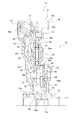
- FIG. 1 shows a torque converter as a fluid type power transmission device according to an embodiment of the present invention.
- An engine is arranged on the left side of FIG. 1, and a transmission is arranged on the right side of FIG.
- a line OO shown in FIG. 1 is a rotation axis of the torque converter.
- the torque converter 1 is a device for transmitting power from a crankshaft of an engine to an input shaft of a transmission, and mainly includes a front cover 2 to which power is input, an impeller 3, a turbine 4, a stator 5, And a lock-up device 6.
- the outer periphery of the front cover 2 and the impeller 3 are fixed by bolts 7, and a fluid chamber is formed by the front cover 2 and the impeller 3.
- the turbine 4 is disposed so as to face the impeller 3 in the fluid chamber.
- the turbine 4 includes a turbine shell 8, a plurality of turbine blades 9 fixed inside the turbine shell 8, and a turbine hub 10 fixed to the inner peripheral portion of the turbine shell 8.
- the turbine hub 10 includes a cylindrical portion 11 that extends in the axial direction, and a disk-shaped flange 12 that extends radially outward from the cylindrical portion 11.
- the inner peripheral portion of the turbine shell 8 is fixed to the outer peripheral portion of the flange 12 by a rivet 13.
- the tubular portion 11 of the turbine hub 10 has a spline hole 11a formed in the inner peripheral portion and a spline shaft 11b formed in the outer peripheral portion. And the input shaft of the transmission which is not illustrated is connected with the spline hole 11a.
- the stator 5 is a mechanism for adjusting the flow of hydraulic oil from the turbine 4 to the impeller 3, and is disposed between the impeller 3 and the turbine 4.
- FIG. 2 shows the lock-up device 6 taken out.
- the lockup device 6 is a device for mechanically connecting the front cover 2 and the turbine 4 when the engine speed reaches a predetermined speed (lockup speed), as shown in FIG. Between the front cover 2 and the turbine 4.
- the lockup device 6 includes a piston 15, an output side unit 16, and a plurality of first torsion springs (first elastic members) 17.
- the piston 15 has a cylindrical portion 15a formed by being bent toward the engine side on the inner peripheral portion. And this cylindrical part 15a is supported by the outer peripheral surface of the cylindrical part 11 of the turbine hub 10 so that sliding is possible in an axial direction and a rotation direction. An annular friction member 18 that is pressed against the side surface of the front cover 2 is fixed to the outer peripheral portion 15 b of the piston 15.
- the output unit 16 includes an output member 20, an inertia member 21, a plurality of second torsion springs (second elastic members) 22, and a hysteresis torque generating mechanism 23.
- the output member 20 includes a driven plate 25 and a hub flange 26.
- the driven plate 25 and the hub flange 26 are fixed to each other by a rivet 27.
- the driven plate 25 is a substantially disk-shaped member whose outer peripheral portion is inclined toward the engine side. The outer peripheral tip is engaged with the end of the first torsion spring 17.
- the hub flange 26 includes a boss 30 and a flange 31 extending radially outward from the outer periphery of one end in the axial direction of the boss 30 as shown in FIG. Have.
- a spline hole 30 a is formed in the inner peripheral portion of the boss 30, and the spline hole 30 a is engaged with the spline shaft 11 b of the turbine hub 10. Further, four arc-shaped concave portions 30b are formed on the outer peripheral surface of the boss 30 at equiangular intervals (90 ° intervals).
- a plurality of window holes 31 a are formed in the outer peripheral portion of the flange 31.
- the second torsion spring 22 is supported by the plurality of window holes 31a.
- a plurality of stopper notches 31b are formed on the inner peripheral side of the window hole 31a.
- the stopper notch 31b has a predetermined length in the circumferential direction.
- the inertia member 21 functions as a dynamic damper that further suppresses fluctuations in rotational speed input from the driven plate 25, and includes first and second inertia plates 34 and 35 and an inertia block 36. .
- the two inertia plates 34 and 35 and the inertia block 36 are fixed to each other by a rivet 37.
- the first and second inertia plates 34 and 35 are arranged to face each other so as to sandwich the flange 31 of the hub flange 26 from both sides in the axial direction.
- a plurality of notches 34a and 35a for supporting the second torsion spring are formed in the radial intermediate portions of the plates 34 and 35, and the second torsion spring 22 is supported by the notches 34a and 35a. .
- a plurality of stopper bent portions 34 b are formed at the inner peripheral end of the first inertia plate 34.
- the stopper bent portion 34 b is formed by bending the inner peripheral end of the first inertia plate 34 toward the axial transmission side, and is inserted into a stopper notch 31 b formed in the flange 31 of the hub flange 26.
- the inertia plates 34 and 35 and the inertia block 36 can be rotated relative to the hub flange 26 in the range (angle range) of the circumferential length of the stopper notch 31b.
- the second inertia plate 35 has a positioning recess 35b on the outer periphery of the notch 35a.
- the positioning recess 35 b is formed to be recessed toward the axial engine side, and the inner peripheral surface thereof can abut on the outer peripheral end surface of the flange 31 of the hub flange 26. Further, the inner peripheral edge of the second inertia plate 35 is bent toward the axial transmission side to form a cylindrical contact portion 35c.
- the inertia block 36 is an annular member, and has a main body portion 36a and an attachment portion 36b formed on the inner peripheral side of the main body portion 36a.
- the mounting portion 36b is fixed to the inertia plates 34 and 35 by the rivet 37 as described above.
- the hysteresis torque generating mechanism 23 is disposed between the flange 31 of the hub flange 26 and the flange 12 of the turbine hub 10 in the axial direction, and the cylindrical shape of the boss 30 of the hub flange 26 and the second inertia plate 35 in the radial direction. It arrange
- the hysteresis torque generating mechanism 23 generates variable hysteresis torque between the hub flange 26 constituting the output member 20 and the second inertia plate 35 constituting the inertia member 21.
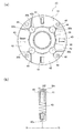
- the hysteresis torque generating mechanism 23 includes a pair of side plates 40, 41, four sliders 42 disposed between the pair of side plates 40, 41, and four sliders.
- a spring 43 provided in correspondence with 42 and four rollers 44.
- FIG. 5 (a) is shown with one side plate removed, and
- FIG. 5 (b) is a partial sectional view of FIG. 5 (a).
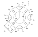
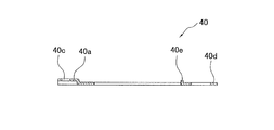
- the side plate 40 is formed in an annular shape as shown in FIG. 7 which is a cross-sectional view taken along the line VII-VII of FIGS. 6 and 6, and has four mounting portions 40a and four slider sliding portions 40b. is doing.
- the four attachment portions 40a are formed at equal angular intervals in the circumferential direction in a part of the outer peripheral portion, and are offset from the slider sliding portion 40b in the axial direction, as is apparent from FIG.
- Each attachment portion 40a is formed with a rivet mounting hole 40c. And these four attaching parts 40a contact
- a space corresponding to the offset of the mounting portion 40a (4 in this example) is provided between the slider sliding portion 40b of one side plate 40 and the slider sliding portion of the other side plate 41. Two separated spaces) are formed.
- the four slider sliding portions 40b are formed between two adjacent mounting portions 40a.
- Each slider sliding portion 40b is formed with an opening 40d for accommodating the spring 43. Further, a bent portion 40e for locking the spring 43 is formed at the inner peripheral end of each slider sliding portion 40b.
- each slider 42 has substantially the same shape as the slider sliding portion 40 b, and the outer peripheral portion is formed in a circular arc shape, and the cylindrical contact formed on the inner peripheral portion of the second inertia plate 35. It can contact
- an opening 42a for accommodating the spring 43 is provided at a position corresponding to the opening 40d of the slider sliding portion 40b.
- the four springs 43 are housed in the corresponding slider sliding portions 40b and openings 40d and 42a of the slider 42, respectively.
- One end on the radially inner side of each spring 43 is in contact with the slider 42, and one end on the radially outer side is in contact with the side plates 40 and 41.
- the slider 42 is urged radially inward when the lock-up device 6 is not rotating (when no centrifugal force is acting), and the cylindrical contact of the second inertia plate 35 is achieved. It does not contact the portion 35c.
- each roller 44 is arranged on the inner peripheral side of the slider 42 as shown in FIG. Specifically, each roller 44 is disposed between an arcuate recess 42 b of two adjacent sliders 42 and an arcuate recess 30 b formed in the boss 30 of the hub flange 26.
- the plurality of first torsion springs 17 are members for elastically connecting the drive plate 50 and the driven plate 25 fixed to the piston 15 in the rotational direction.
- the first torsion spring 17 is supported by a plurality of members such as the drive plate 50 and is restricted from moving in the axial direction and the radial direction.
- the difference between the characteristics E2 and E3 in the low speed range is due to the magnitude of the hysteresis torque in the hysteresis torque generating mechanism 23. That is, characteristic E2 is when the hysteresis torque is relatively large, and characteristic E3 is when the hysteresis torque is relatively small.
- characteristic E2 the rotational speed fluctuation of the turbine decreases near the engine speed lower than 1200 rpm, reaches a maximum near 1500 rpm, and gradually decreases in the higher engine speed range.
- the rotational speed fluctuation of the turbine shows a minimum value smaller than the characteristic E2 when the engine speed exceeds 1200 rpm, and becomes the maximum exceeding the characteristic E2 near 1600 rpm.
- the rotational speed fluctuation of the turbine is smaller when the hysteresis torque is smaller in the engine speed range where the engine speed is low, and is smaller when the hysteresis torque is greater in the intermediate speed range.
- the influence on the turbine rotational speed fluctuation due to the magnitude of the hysteresis torque is small.
- the hysteresis torque generating mechanism 23 is configured such that the hysteresis torque changes depending on the rotation speed range. Specifically, the hysteresis torque generated by the hysteresis torque generating mechanism 23 is small in a region where the engine speed is low, and is large in regions where the engine speed is high.
- the centrifugal force F0 acting on the slider 42 is relatively small in the low rotational speed range. For this reason, the slider 42 is urged radially inward by the spring 43, and the outer peripheral surface of the slider 42 is not in contact with the cylindrical contact portion 35 c of the second inertia plate 35. Therefore, the hysteresis torque is relatively small. That is, only the hysteresis torque due to the friction of each part.
- the roller 44 contacts the hub flange 26 at a point P1, and receives a force F1 from the contact point P1. Further, since the roller 44 is in contact with the slider 42 at the point P2, the slider 42 receives the force F2 from the roller 44. Then, the slider 42 receives a further clockwise moment, and as a result, the outer peripheral surface of the slider 42 is strongly pressed against the cylindrical contact portion 35c.
- a hysteresis torque larger than the hysteresis torque in the low rotation speed region is generated between the inertia member 21 (second inertia plate 35) and the hub flange 26 that are rotating relative to each other. .
- the characteristic of the turbine rotational speed fluctuation is characteristic E3 in the low rotational speed range and characteristic E2 in the middle rotational speed range to the high rotational speed range as shown in FIG. For this reason, the turbine rotational speed fluctuation can be kept small in the entire engine speed range.
- the configuration of the hysteresis torque generating mechanism is not limited to the above embodiment. Any configuration may be used as long as the hysteresis torque generated by the rotational speed region changes.
- a torque converter is described as an example of the fluid power transmission device, but the fluid power transmission device may be a fluid coupling that does not have a stator.
- the lock-up rotation speed of the lock-up device can be set to a lower rotation speed, and the turbine rotation fluctuation can be suppressed in a wide rotation speed range. For this reason, low fuel consumption can be realized.
Landscapes
- Engineering & Computer Science (AREA)
- General Engineering & Computer Science (AREA)
- Mechanical Engineering (AREA)
- Physics & Mathematics (AREA)
- Acoustics & Sound (AREA)
- Aviation & Aerospace Engineering (AREA)
- Mechanical Operated Clutches (AREA)
Abstract
Description
図1に、本発明の一実施形態による流体式動力伝達装置としてのトルクコンバータを示す。図1の左側にはエンジンが配置され、図1の右側にはトランスミッションが配置されている。図1に示す線O-Oはトルクコンバータの回転軸線である。
図2にロックアップ装置6を取り出して示している。ロックアップ装置6は、エンジン回転数が所定の回転数(ロックアップ回転数)に到達したときに、フロントカバー2とタービン4とを機械的に連結するための装置であり、図1に示すようにフロントカバー2とタービン4との間に配置されている。このロックアップ装置6は、ピストン15と、出力側ユニット16と、複数の第1トーションスプリング(第1弾性部材)17と、を有している。
ピストン15は、内周部にエンジン側に折り曲げられて形成された筒状部15aを有している。そして、この筒状部15aが、タービンハブ10の筒状部11の外周面に、軸方向及び回転方向に摺動自在に支持されている。また、ピストン15の外周部15bにはフロントカバー2の側面に押し付けられる環状の摩擦部材18が固定されている。
出力側ユニット16は、出力部材20と、イナーシャ部材21と、複数の第2トーションスプリング(第2弾性部材)22と、ヒステリシストルク発生機構23と、を有している。
出力部材20は、ドリブンプレート25と、ハブフランジ26と、から構成されている。ドリブンプレート25とハブフランジ26とは、リベット27によって互いに固定されている。
イナーシャ部材21は、ドリブンプレート25から入力される回転速度変動をさらに抑制するダイナミックダンパとして機能するものであり、第1及び第2イナーシャプレート34,35と、イナーシャブロック36と、から構成されている。2つのイナーシャプレート34,35とイナーシャブロック36とは互いにリベット37によって固定されている。
ヒステリシストルク発生機構23は、軸方向においてはハブフランジ26のフランジ31とタービンハブ10のフランジ12との間に配置され、径方向においてはハブフランジ26のボス30と第2イナーシャプレート35の筒状当接部35cとの間に配置されている。このヒステリシストルク発生機構23は、出力部材20を構成するハブフランジ26とイナーシャ部材21を構成する第2イナーシャプレート35との間で可変のヒステリシストルクを発生するものである。
複数の第1トーションスプリング17は、図2に示すように、ピストン15に固定されたドライブプレート50とドリブンプレート25とを回転方向に弾性的に連結するための部材である。第1トーションスプリング17は、ドライブプレート50等の複数の部材により支持されており、軸方向及び径方向の移動が規制されている。
トルクコンバータ自体の動作について簡単に説明する。
出力側ユニット16では、ドリブンプレート25に入力された動力がハブフランジ26を介してタービンハブ10に伝達される。このとき、ハブフランジ26にはイナーシャ部材21が設けられているので、エンジンの回転変動を効果的に抑制することができる。以下。この点について詳細に説明する。
図10を用いて、回転数域によってヒステリシストルクが変化する動作について説明する。
(1)低回転数域では小さいヒステリシストルクを発生し、中回転数域から高回転数域ではより大きなヒステリシストルクを発生するので、広い回転数域でタービンの回転速度変動を抑えることができる。
本発明は以上のような実施形態に限定されるものではなく、本発明の範囲を逸脱することなく種々の変形又は修正が可能である。
2 フロントカバー
3 インペラ
4 タービン
6 ロックアップ装置
10 タービンハブ
15 ピストン
16 出力側ユニット
17 第1トーションスプリング(第1弾性部材)
20 出力部材
21 イナーシャ部材
22 第2トーションスプリング(第2弾性部材)
23 ヒステリシストルク発生機構
25 ドリブンプレート
26 ハブフランジ
30 ボス
31 フランジ
34,35 イナーシャプレート
36 イナーシャブロック
40,41 サイドプレート
42 スライダ
43 スプリング
44 ローラ
Claims (7)
- フロントカバーから流体式動力伝達装置のタービンに機械的に動力を連結するためのロックアップ装置であって、
前記フロントカバーに押し付けられるピストンと、
前記タービンと一体回転可能に設けられた出力側ユニットと、
を備え、
前記出力側ユニットは、
前記タービンに固定された出力部材と、
前記出力部材に対して相対回転可能に設けられたイナーシャ部材と、
前記イナーシャ部材と前記出力部材とを回転方向に弾性的に連結する弾性部材と、
前記イナーシャ部材と前記出力部材との間に配置され、前記イナーシャ部材と前記出力部材との間で可変のヒステリシストルクを発生するヒステリシストルク発生機構と、
を有する流体式動力伝達装置のロックアップ装置。 - 前記ヒステリシストルク発生機構は、低回転数域では第1ヒステリシストルクを発生し、中回転数域から高回転数域では前記第1ヒステリシストルクよりも大きな第2ヒステリシストルクを発生する、請求項1に記載の流体式動力伝達装置のロックアップ装置。
- 前記出力部材は、前記ピストンから動力が入力されるドリブンプレートと、前記ドリブンプレートの内周部に固定されるとともに前記タービンに固定されたハブフランジと、を有し、
前記イナーシャ部材は、前記弾性部材を介して前記ハブフランジに回転方向に弾性的に連結された環状のイナーシャプレートと、前記イナーシャプレートの外周部に固定されたイナーシャブロックと、を有し、
前記ヒステリシストルク発生機構は前記ハブフランジの外周と前記イナーシャプレートの内周部との間に配置されている、
請求項2に記載の流体式動力伝達装置のロックアップ装置。 - 前記ヒステリシストルク発生機構は、前記ハブフランジとともに回転し径方向に移動自在な複数のスライダを有し、前記複数のスライダは前記ハブフランジが所定の回転数以上のときに遠心力で径方向外方に移動して前記イナーシャプレートに当接する、請求項3に記載の流体式動力伝達装置のロックアップ装置。
- 前記ヒステリシストルク発生機構は複数の前記スライダを前記イナーシャプレートに押し付ける押付機構をさらに有している、請求項4に記載の流体式動力伝達装置のロックアップ装置。
- 前記押付機構は、前記ハブフランジと複数の前記スライダのそれぞれとの間に配置され、回転変動により複数の前記スライダを前記イナーシャプレートに押圧する複数のローラを有している、請求項5に記載の流体式動力伝達装置のロックアップ装置。
- 前記ピストンと前記出力側ユニットとを回転方向に弾性的に連結する弾性部材をさらに備えた、請求項1から6のいずれかに記載の流体式動力伝達装置のロックアップ装置。
Priority Applications (3)
| Application Number | Priority Date | Filing Date | Title |
|---|---|---|---|
| DE112011103510.1T DE112011103510B4 (de) | 2010-10-19 | 2011-08-23 | Überbrückungsvorrichtung für eine Kraftübertragungsvorrichtung des Fluidtyps |
| US13/879,707 US9506547B2 (en) | 2010-10-19 | 2011-08-23 | Lock-up device for fluid type power transmission device |
| CN201180050126.4A CN103189670B (zh) | 2010-10-19 | 2011-08-23 | 流体式动力传递装置的锁定装置 |
Applications Claiming Priority (2)
| Application Number | Priority Date | Filing Date | Title |
|---|---|---|---|
| JP2010234338A JP4932934B2 (ja) | 2010-10-19 | 2010-10-19 | 流体式動力伝達装置のロックアップ装置 |
| JP2010-234338 | 2010-10-19 |
Publications (1)
| Publication Number | Publication Date |
|---|---|
| WO2012053280A1 true WO2012053280A1 (ja) | 2012-04-26 |
Family
ID=45975003
Family Applications (1)
| Application Number | Title | Priority Date | Filing Date |
|---|---|---|---|
| PCT/JP2011/068918 Ceased WO2012053280A1 (ja) | 2010-10-19 | 2011-08-23 | 流体式動力伝達装置のロックアップ装置 |
Country Status (5)
| Country | Link |
|---|---|
| US (1) | US9506547B2 (ja) |
| JP (1) | JP4932934B2 (ja) |
| CN (1) | CN103189670B (ja) |
| DE (1) | DE112011103510B4 (ja) |
| WO (1) | WO2012053280A1 (ja) |
Cited By (4)
| Publication number | Priority date | Publication date | Assignee | Title |
|---|---|---|---|---|
| US9732835B2 (en) | 2013-07-11 | 2017-08-15 | Exedy Corporation | Lockup device for torque converter |
| US9784352B2 (en) | 2013-06-04 | 2017-10-10 | Exedy Corporation | Lock-up device for torque converter |
| US10030740B2 (en) | 2013-06-04 | 2018-07-24 | Exedy Corporation | Lock-up device for torque converter |
| US10451157B2 (en) | 2014-10-29 | 2019-10-22 | Exedy Corporation | Lock-up device for torque converter |
Families Citing this family (24)
| Publication number | Priority date | Publication date | Assignee | Title |
|---|---|---|---|---|
| JP5326008B2 (ja) * | 2012-02-07 | 2013-10-30 | 株式会社エクセディ | ダイナミックダンパ装置及び流体式動力伝達装置のロックアップ装置 |
| JP2013256963A (ja) * | 2012-06-11 | 2013-12-26 | Exedy Corp | 流体式動力伝達装置 |
| JP5972804B2 (ja) * | 2013-01-22 | 2016-08-17 | 株式会社エクセディ | ダイナミックダンパ装置及びトルクコンバータのロックアップ装置 |
| JP5639204B2 (ja) * | 2013-02-06 | 2014-12-10 | 株式会社エクセディ | トルクコンバータのロックアップ装置 |
| JP6010476B2 (ja) * | 2013-02-07 | 2016-10-19 | 株式会社エクセディ | ダイナミックダンパ装置 |
| JP6182433B2 (ja) * | 2013-11-12 | 2017-08-16 | 株式会社エクセディ | ダイナミックダンパ装置及びトルクコンバータのロックアップ装置 |
| JP6163412B2 (ja) * | 2013-11-20 | 2017-07-12 | 株式会社エクセディ | トルクコンバータのロックアップ装置 |
| JP6277053B2 (ja) * | 2014-04-23 | 2018-02-07 | 本田技研工業株式会社 | トルクコンバータ |
| JP6334284B2 (ja) | 2014-06-16 | 2018-05-30 | 株式会社エクセディ | 動力伝達装置及びトルクコンバータのロックアップ装置 |
| JP5791772B1 (ja) | 2014-08-29 | 2015-10-07 | 株式会社エクセディ | 流体式動力伝達装置 |
| JP5791773B1 (ja) * | 2014-08-29 | 2015-10-07 | 株式会社エクセディ | 流体式動力伝達装置 |
| JP6530604B2 (ja) * | 2015-01-06 | 2019-06-12 | 株式会社エクセディ | 動力伝達装置 |
| US10570964B2 (en) | 2015-03-19 | 2020-02-25 | Honda Motor Co., Ltd. | Vibration absorber |
| FR3034154B1 (fr) * | 2015-03-27 | 2017-03-17 | Valeo Embrayages | Composant pour systeme de transmission, notamment disque d'embrayage |
| FR3034155B1 (fr) * | 2015-03-27 | 2017-09-15 | Valeo Embrayages | Dispositif d'amortissement d'oscillations de torsion |
| JP5951081B2 (ja) * | 2015-06-12 | 2016-07-13 | 株式会社エクセディ | トルクコンバータのロックアップ装置 |
| JP5951082B2 (ja) * | 2015-06-12 | 2016-07-13 | 株式会社エクセディ | トルクコンバータのロックアップ装置 |
| FR3037626B1 (fr) | 2015-06-18 | 2018-08-10 | Valeo Embrayages | Dispositif de filtration des vibrations |
| KR101707804B1 (ko) * | 2015-07-16 | 2017-02-17 | 한국파워트레인 주식회사 | 진자를 이용한 진동저감장치를 포함하는 차량용 토크 컨버터 |
| FR3048475B1 (fr) * | 2016-03-04 | 2018-09-28 | Valeo Embrayages | Dispositif d'amortissement |
| JP6637802B2 (ja) * | 2016-03-18 | 2020-01-29 | 株式会社エクセディ | 振動低減装置 |
| JP6725314B2 (ja) * | 2016-05-16 | 2020-07-15 | 株式会社エクセディ | トルクコンバータのロックアップ装置 |
| US10393247B2 (en) | 2016-05-23 | 2019-08-27 | Valeo Embrayages | Hydrokinetic torque coupling device with torsional vibration damper in combination with two vibration absorbers |
| KR101844492B1 (ko) | 2016-09-30 | 2018-04-02 | 주식회사 카펙발레오 | 차량용 토크 컨버터 |
Citations (5)
| Publication number | Priority date | Publication date | Assignee | Title |
|---|---|---|---|---|
| JP2007024255A (ja) * | 2005-07-20 | 2007-02-01 | Exedy Corp | 遠心式クラッチ装置 |
| JP2007024254A (ja) * | 2005-07-20 | 2007-02-01 | Exedy Corp | 遠心式クラッチ装置 |
| JP2007247723A (ja) * | 2006-03-14 | 2007-09-27 | Exedy Corp | ダンパー機構 |
| JP2009197889A (ja) * | 2008-02-21 | 2009-09-03 | Mazda Motor Corp | 流体伝動装置 |
| JP2009293671A (ja) * | 2008-06-03 | 2009-12-17 | Exedy Corp | ロックアップ装置および流体式動力伝達装置 |
Family Cites Families (21)
| Publication number | Priority date | Publication date | Assignee | Title |
|---|---|---|---|---|
| US2102524A (en) * | 1935-04-16 | 1937-12-14 | Schneider & Cie | Centrifugal clutch |
| US3519112A (en) * | 1968-03-13 | 1970-07-07 | Sergio Verzolla | Fluid coupling with centrifugal roller lock-up clutch |
| DE3236621C1 (de) * | 1982-10-02 | 1984-02-09 | Daimler-Benz Ag, 7000 Stuttgart | UEberbrueckungskupplung mit einer vormontierten Kolben-Daempfer-Baueinheit fuer eine hydrodynamische Stroemungseinheit |
| FR2602560B1 (fr) * | 1986-08-06 | 1990-11-02 | Valeo | Unite d'embrayage, et applications notamment friction d'embrayage, embrayage et organe d'accouplement hydraulique comportant une telle unite, en particulier pour vehicule automobile |
| US4982821A (en) * | 1987-12-07 | 1991-01-08 | Kabushiki Kaisha Daikin Seisakusho | Friction device of lockup clutch |
| US5195621A (en) * | 1992-05-18 | 1993-03-23 | General Motors Corporation | Torque converter and clutch with a turbine ring friction interface |
| JP2001500957A (ja) * | 1997-05-09 | 2001-01-23 | オートモーティヴ・プロダクツ・パブリック・リミテッド・カンパニー | 二質量フライホイール |
| DE19804227B4 (de) * | 1998-02-04 | 2006-03-09 | Zf Sachs Ag | Überbrückungskupplung mit einer Ausgleichsschwungmasse am Torsionsschwingungsdämpfer |
| JP4048487B2 (ja) * | 2003-03-07 | 2008-02-20 | トヨタ自動車株式会社 | ダンパ装置およびロックアップクラッチ装置 |
| JP4395343B2 (ja) * | 2003-08-01 | 2010-01-06 | 株式会社エクセディ | ロックアップ装置のダンパー機構 |
| EP1548313B2 (de) | 2003-12-23 | 2016-09-28 | Schaeffler Technologies AG & Co. KG | Drehmomentübertragungseinrichtung |
| US20070251788A1 (en) * | 2006-05-01 | 2007-11-01 | Luk Lamellen Und Kupplungsbau Beteiligungs Kg | Drive plate and seal for a torque converter |
| DE102007026656A1 (de) * | 2006-06-13 | 2007-12-20 | Luk Lamellen Und Kupplungsbau Beteiligungs Kg | Geschmiedete Antriebsnocken für ein Kolbenblech |
| JP5473933B2 (ja) * | 2007-11-29 | 2014-04-16 | シェフラー テクノロジーズ アクチエンゲゼルシャフト ウント コンパニー コマンディートゲゼルシャフト | 回転数適応型の動吸振器を備えた力伝達装置および減衰特性を改善するための方法 |
| DE102009042837A1 (de) * | 2008-10-16 | 2010-04-22 | Luk Lamellen Und Kupplungsbau Beteiligungs Kg | Hydrodynamischer Drehmomentwandler |
| DE102010014674B4 (de) * | 2009-04-27 | 2019-07-04 | Schaeffler Technologies AG & Co. KG | Hydrodynamischer Drehmomentwandler |
| WO2011006468A1 (de) * | 2009-07-16 | 2011-01-20 | Schaeffler Technologies Gmbh & Co. Kg | Drehmomentübertragungseinrichtung |
| DE102011101156A1 (de) * | 2010-05-18 | 2011-11-24 | Schaeffler Technologies Gmbh & Co. Kg | Einreihiger Seriendämpfer mit Antriebsflansch |
| JP5556551B2 (ja) * | 2010-09-30 | 2014-07-23 | アイシン・エィ・ダブリュ株式会社 | 流体伝動装置 |
| WO2012049762A1 (ja) * | 2010-10-15 | 2012-04-19 | トヨタ自動車株式会社 | 振動減衰装置 |
| US9080635B2 (en) * | 2011-04-19 | 2015-07-14 | Schaeffler Technologies AG & Co. KG | Hardened turbine plate |
-
2010
- 2010-10-19 JP JP2010234338A patent/JP4932934B2/ja active Active
-
2011
- 2011-08-23 DE DE112011103510.1T patent/DE112011103510B4/de active Active
- 2011-08-23 WO PCT/JP2011/068918 patent/WO2012053280A1/ja not_active Ceased
- 2011-08-23 US US13/879,707 patent/US9506547B2/en active Active
- 2011-08-23 CN CN201180050126.4A patent/CN103189670B/zh active Active
Patent Citations (5)
| Publication number | Priority date | Publication date | Assignee | Title |
|---|---|---|---|---|
| JP2007024255A (ja) * | 2005-07-20 | 2007-02-01 | Exedy Corp | 遠心式クラッチ装置 |
| JP2007024254A (ja) * | 2005-07-20 | 2007-02-01 | Exedy Corp | 遠心式クラッチ装置 |
| JP2007247723A (ja) * | 2006-03-14 | 2007-09-27 | Exedy Corp | ダンパー機構 |
| JP2009197889A (ja) * | 2008-02-21 | 2009-09-03 | Mazda Motor Corp | 流体伝動装置 |
| JP2009293671A (ja) * | 2008-06-03 | 2009-12-17 | Exedy Corp | ロックアップ装置および流体式動力伝達装置 |
Cited By (4)
| Publication number | Priority date | Publication date | Assignee | Title |
|---|---|---|---|---|
| US9784352B2 (en) | 2013-06-04 | 2017-10-10 | Exedy Corporation | Lock-up device for torque converter |
| US10030740B2 (en) | 2013-06-04 | 2018-07-24 | Exedy Corporation | Lock-up device for torque converter |
| US9732835B2 (en) | 2013-07-11 | 2017-08-15 | Exedy Corporation | Lockup device for torque converter |
| US10451157B2 (en) | 2014-10-29 | 2019-10-22 | Exedy Corporation | Lock-up device for torque converter |
Also Published As
| Publication number | Publication date |
|---|---|
| DE112011103510T5 (de) | 2013-12-24 |
| CN103189670A (zh) | 2013-07-03 |
| CN103189670B (zh) | 2015-11-25 |
| DE112011103510B4 (de) | 2022-02-24 |
| US9506547B2 (en) | 2016-11-29 |
| US20130206529A1 (en) | 2013-08-15 |
| JP2012087856A (ja) | 2012-05-10 |
| JP4932934B2 (ja) | 2012-05-16 |
Similar Documents
| Publication | Publication Date | Title |
|---|---|---|
| JP4932934B2 (ja) | 流体式動力伝達装置のロックアップ装置 | |
| JP5326008B2 (ja) | ダイナミックダンパ装置及び流体式動力伝達装置のロックアップ装置 | |
| JP5555784B1 (ja) | ダイナミックダンパ装置 | |
| JP6010476B2 (ja) | ダイナミックダンパ装置 | |
| CN105339706B (zh) | 液力变矩器的锁定装置 | |
| CN104937311B (zh) | 扭矩转换器的锁止装置 | |
| CN102652234B (zh) | 扭矩转换器用锁定装置 | |
| WO2011070852A1 (ja) | トルクコンバータ | |
| CN102472378A (zh) | 转矩变换器用锁定装置 | |
| JP2009041737A (ja) | 流体式トルク伝達装置 | |
| JP2013256963A (ja) | 流体式動力伝達装置 | |
| JP5875393B2 (ja) | ダイナミックダンパ装置及び流体式動力伝達装置のロックアップ装置 | |
| JP7300284B2 (ja) | トルク変動抑制装置、及びトルクコンバータ | |
| JP5972804B2 (ja) | ダイナミックダンパ装置及びトルクコンバータのロックアップ装置 | |
| JP5875392B2 (ja) | ダイナミックダンパ装置及び流体式動力伝達装置のロックアップ装置 | |
| JP7263066B2 (ja) | トルク変動抑制装置、及びトルクコンバータ | |
| JP6539180B2 (ja) | トルク変動抑制装置、トルクコンバータ、及び動力伝達装置 | |
| JP7218221B2 (ja) | トルク変動抑制装置、及びトルクコンバータ | |
| JP7232667B2 (ja) | トルク変動抑制装置 | |
| JP2006162054A5 (ja) | ||
| CN111120531B (zh) | 扭转振动减轻装置 | |
| JP6682572B2 (ja) | トルク変動抑制装置 | |
| JP2009019649A (ja) | ロックアップダンパー | |
| JP2020133689A (ja) | 捩り振動低減装置 | |
| JP2001065637A (ja) | ダンパー機構 |
Legal Events
| Date | Code | Title | Description |
|---|---|---|---|
| 121 | Ep: the epo has been informed by wipo that ep was designated in this application |
Ref document number: 11834122 Country of ref document: EP Kind code of ref document: A1 |
|
| WWE | Wipo information: entry into national phase |
Ref document number: 13879707 Country of ref document: US |
|
| WWE | Wipo information: entry into national phase |
Ref document number: 112011103510 Country of ref document: DE Ref document number: 1120111035101 Country of ref document: DE |
|
| 122 | Ep: pct application non-entry in european phase |
Ref document number: 11834122 Country of ref document: EP Kind code of ref document: A1 |