WO2012036127A1 - 非水二次電池 - Google Patents
非水二次電池 Download PDFInfo
- Publication number
- WO2012036127A1 WO2012036127A1 PCT/JP2011/070743 JP2011070743W WO2012036127A1 WO 2012036127 A1 WO2012036127 A1 WO 2012036127A1 JP 2011070743 W JP2011070743 W JP 2011070743W WO 2012036127 A1 WO2012036127 A1 WO 2012036127A1
- Authority
- WO
- WIPO (PCT)
- Prior art keywords
- negative electrode
- carbon
- sio
- secondary battery
- separator
- Prior art date
Links
Images

Classifications
-
- H—ELECTRICITY
- H01—ELECTRIC ELEMENTS
- H01M—PROCESSES OR MEANS, e.g. BATTERIES, FOR THE DIRECT CONVERSION OF CHEMICAL ENERGY INTO ELECTRICAL ENERGY
- H01M4/00—Electrodes
- H01M4/02—Electrodes composed of, or comprising, active material
- H01M4/13—Electrodes for accumulators with non-aqueous electrolyte, e.g. for lithium-accumulators; Processes of manufacture thereof
- H01M4/133—Electrodes based on carbonaceous material, e.g. graphite-intercalation compounds or CFx
-
- H—ELECTRICITY
- H01—ELECTRIC ELEMENTS
- H01M—PROCESSES OR MEANS, e.g. BATTERIES, FOR THE DIRECT CONVERSION OF CHEMICAL ENERGY INTO ELECTRICAL ENERGY
- H01M4/00—Electrodes
- H01M4/02—Electrodes composed of, or comprising, active material
- H01M4/36—Selection of substances as active materials, active masses, active liquids
- H01M4/48—Selection of substances as active materials, active masses, active liquids of inorganic oxides or hydroxides
-
- C—CHEMISTRY; METALLURGY
- C01—INORGANIC CHEMISTRY
- C01B—NON-METALLIC ELEMENTS; COMPOUNDS THEREOF; METALLOIDS OR COMPOUNDS THEREOF NOT COVERED BY SUBCLASS C01C
- C01B33/00—Silicon; Compounds thereof
- C01B33/113—Silicon oxides; Hydrates thereof
-
- H—ELECTRICITY
- H01—ELECTRIC ELEMENTS
- H01M—PROCESSES OR MEANS, e.g. BATTERIES, FOR THE DIRECT CONVERSION OF CHEMICAL ENERGY INTO ELECTRICAL ENERGY
- H01M4/00—Electrodes
- H01M4/02—Electrodes composed of, or comprising, active material
- H01M4/13—Electrodes for accumulators with non-aqueous electrolyte, e.g. for lithium-accumulators; Processes of manufacture thereof
- H01M4/131—Electrodes based on mixed oxides or hydroxides, or on mixtures of oxides or hydroxides, e.g. LiCoOx
-
- H—ELECTRICITY
- H01—ELECTRIC ELEMENTS
- H01M—PROCESSES OR MEANS, e.g. BATTERIES, FOR THE DIRECT CONVERSION OF CHEMICAL ENERGY INTO ELECTRICAL ENERGY
- H01M10/00—Secondary cells; Manufacture thereof
- H01M10/05—Accumulators with non-aqueous electrolyte
- H01M10/052—Li-accumulators
-
- H—ELECTRICITY
- H01—ELECTRIC ELEMENTS
- H01M—PROCESSES OR MEANS, e.g. BATTERIES, FOR THE DIRECT CONVERSION OF CHEMICAL ENERGY INTO ELECTRICAL ENERGY
- H01M10/00—Secondary cells; Manufacture thereof
- H01M10/05—Accumulators with non-aqueous electrolyte
- H01M10/056—Accumulators with non-aqueous electrolyte characterised by the materials used as electrolytes, e.g. mixed inorganic/organic electrolytes
- H01M10/0564—Accumulators with non-aqueous electrolyte characterised by the materials used as electrolytes, e.g. mixed inorganic/organic electrolytes the electrolyte being constituted of organic materials only
- H01M10/0566—Liquid materials
-
- H—ELECTRICITY
- H01—ELECTRIC ELEMENTS
- H01M—PROCESSES OR MEANS, e.g. BATTERIES, FOR THE DIRECT CONVERSION OF CHEMICAL ENERGY INTO ELECTRICAL ENERGY
- H01M4/00—Electrodes
- H01M4/02—Electrodes composed of, or comprising, active material
- H01M4/36—Selection of substances as active materials, active masses, active liquids
- H01M4/362—Composites
- H01M4/366—Composites as layered products
-
- H—ELECTRICITY
- H01—ELECTRIC ELEMENTS
- H01M—PROCESSES OR MEANS, e.g. BATTERIES, FOR THE DIRECT CONVERSION OF CHEMICAL ENERGY INTO ELECTRICAL ENERGY
- H01M4/00—Electrodes
- H01M4/02—Electrodes composed of, or comprising, active material
- H01M4/36—Selection of substances as active materials, active masses, active liquids
- H01M4/48—Selection of substances as active materials, active masses, active liquids of inorganic oxides or hydroxides
- H01M4/483—Selection of substances as active materials, active masses, active liquids of inorganic oxides or hydroxides for non-aqueous cells
-
- H—ELECTRICITY
- H01—ELECTRIC ELEMENTS
- H01M—PROCESSES OR MEANS, e.g. BATTERIES, FOR THE DIRECT CONVERSION OF CHEMICAL ENERGY INTO ELECTRICAL ENERGY
- H01M4/00—Electrodes
- H01M4/02—Electrodes composed of, or comprising, active material
- H01M4/36—Selection of substances as active materials, active masses, active liquids
- H01M4/48—Selection of substances as active materials, active masses, active liquids of inorganic oxides or hydroxides
- H01M4/52—Selection of substances as active materials, active masses, active liquids of inorganic oxides or hydroxides of nickel, cobalt or iron
- H01M4/525—Selection of substances as active materials, active masses, active liquids of inorganic oxides or hydroxides of nickel, cobalt or iron of mixed oxides or hydroxides containing iron, cobalt or nickel for inserting or intercalating light metals, e.g. LiNiO2, LiCoO2 or LiCoOxFy
-
- H—ELECTRICITY
- H01—ELECTRIC ELEMENTS
- H01M—PROCESSES OR MEANS, e.g. BATTERIES, FOR THE DIRECT CONVERSION OF CHEMICAL ENERGY INTO ELECTRICAL ENERGY
- H01M4/00—Electrodes
- H01M4/02—Electrodes composed of, or comprising, active material
- H01M4/36—Selection of substances as active materials, active masses, active liquids
- H01M4/58—Selection of substances as active materials, active masses, active liquids of inorganic compounds other than oxides or hydroxides, e.g. sulfides, selenides, tellurides, halogenides or LiCoFy; of polyanionic structures, e.g. phosphates, silicates or borates
- H01M4/583—Carbonaceous material, e.g. graphite-intercalation compounds or CFx
- H01M4/587—Carbonaceous material, e.g. graphite-intercalation compounds or CFx for inserting or intercalating light metals
-
- Y—GENERAL TAGGING OF NEW TECHNOLOGICAL DEVELOPMENTS; GENERAL TAGGING OF CROSS-SECTIONAL TECHNOLOGIES SPANNING OVER SEVERAL SECTIONS OF THE IPC; TECHNICAL SUBJECTS COVERED BY FORMER USPC CROSS-REFERENCE ART COLLECTIONS [XRACs] AND DIGESTS
- Y02—TECHNOLOGIES OR APPLICATIONS FOR MITIGATION OR ADAPTATION AGAINST CLIMATE CHANGE
- Y02E—REDUCTION OF GREENHOUSE GAS [GHG] EMISSIONS, RELATED TO ENERGY GENERATION, TRANSMISSION OR DISTRIBUTION
- Y02E60/00—Enabling technologies; Technologies with a potential or indirect contribution to GHG emissions mitigation
- Y02E60/10—Energy storage using batteries
-
- Y—GENERAL TAGGING OF NEW TECHNOLOGICAL DEVELOPMENTS; GENERAL TAGGING OF CROSS-SECTIONAL TECHNOLOGIES SPANNING OVER SEVERAL SECTIONS OF THE IPC; TECHNICAL SUBJECTS COVERED BY FORMER USPC CROSS-REFERENCE ART COLLECTIONS [XRACs] AND DIGESTS
- Y02—TECHNOLOGIES OR APPLICATIONS FOR MITIGATION OR ADAPTATION AGAINST CLIMATE CHANGE
- Y02P—CLIMATE CHANGE MITIGATION TECHNOLOGIES IN THE PRODUCTION OR PROCESSING OF GOODS
- Y02P70/00—Climate change mitigation technologies in the production process for final industrial or consumer products
- Y02P70/50—Manufacturing or production processes characterised by the final manufactured product
-
- Y—GENERAL TAGGING OF NEW TECHNOLOGICAL DEVELOPMENTS; GENERAL TAGGING OF CROSS-SECTIONAL TECHNOLOGIES SPANNING OVER SEVERAL SECTIONS OF THE IPC; TECHNICAL SUBJECTS COVERED BY FORMER USPC CROSS-REFERENCE ART COLLECTIONS [XRACs] AND DIGESTS
- Y02—TECHNOLOGIES OR APPLICATIONS FOR MITIGATION OR ADAPTATION AGAINST CLIMATE CHANGE
- Y02T—CLIMATE CHANGE MITIGATION TECHNOLOGIES RELATED TO TRANSPORTATION
- Y02T10/00—Road transport of goods or passengers
- Y02T10/60—Other road transportation technologies with climate change mitigation effect
- Y02T10/70—Energy storage systems for electromobility, e.g. batteries
Definitions
- the present invention relates to a non-aqueous secondary battery having good storage characteristics.
- Non-aqueous secondary batteries such as lithium ion secondary batteries are widely used as power sources for various portable devices because of their high voltage and high capacity. Furthermore, in recent years, power tools such as electric tools, electric vehicles, electric bicycles, and other medium-sized and large-sized applications are spreading.
- SiO x has a large volume expansion / contraction associated with the charge / discharge reaction, particles are pulverized for each charge / discharge cycle of the battery, and Si deposited on the surface reacts with the non-aqueous electrolyte to cause an irreversible capacity. It is also known that problems such as an increase in battery capacity and battery expansion due to charge / discharge occur.
- SiO x has a fine shape, a certain effect can be recognized in improving the load characteristics of the battery, but there is still room for improvement in that SiO x itself is a material with low conductivity. It was left.
- JP 2004-47404 A Japanese Patent Laid-Open No. 2005-259697 JP 2008-210618A
- the non-aqueous secondary battery using SiO x as the negative electrode has not yet satisfied various characteristics required for the battery, and in particular, improvement of storage characteristics has been a main issue.
- the present invention has been made in view of the above circumstances, and provides a non-aqueous secondary battery having a high capacity and excellent storage characteristics.
- the non-aqueous secondary battery of the present invention is a non-aqueous secondary battery having a positive electrode, a negative electrode, a non-aqueous electrolyte, and a separator, and the negative electrode has carbon on the surface of a core material containing Si and O as constituent elements.
- a composite comprising a coating layer and a negative electrode active material comprising a graphitic carbon material is contained, the carbon content in the composite is 10 to 30% by mass, and the Raman spectrum of the composite is converted to a laser wavelength.
- the intensity ratio I 510 / I 1343 of the peak intensity I 1343 of 1343cm -1, which derived from the carbon, and 0.25 or less When the crystallite size of the Si phase contained in the core material is measured by an X-ray diffraction method using CuK ⁇ rays, the half width of the (111) diffraction peak of Si is less than 3.0 °. Also It is.
- a non-aqueous secondary battery having a high capacity and excellent storage characteristics can be provided.
- FIG. 1A is a plan view of the non-aqueous secondary battery of the present invention
- FIG. 1B is a cross-sectional view of the non-aqueous secondary battery of the present invention
- FIG. 2 is a perspective view showing the appearance of the non-aqueous secondary battery of the present invention.
- the non-aqueous secondary battery of the present invention has a negative electrode, a positive electrode, a non-aqueous electrolyte, and a separator, and there is no particular limitation on the configuration and structure other than the negative electrode, and conventionally known non-aqueous secondary batteries Various configurations and structures adopted in the above can be applied. Below, each component of the non-aqueous secondary battery of this invention is explained in full detail.
- the negative electrode according to the non-aqueous secondary battery of the present invention has, for example, a structure having a negative electrode mixture layer containing a negative electrode active material, a binder, and optionally a conductive auxiliary agent on one or both sides of the current collector Can be used.
- the negative electrode active material used for the negative electrode of the non-aqueous secondary battery of the present invention comprises a composite in which a carbon coating layer is formed on the surface of a core material containing Si and O as constituent elements, and a graphitic carbon material. Is included.
- the core material may be a complex oxide of Si and another metal in addition to an oxide of Si, and may include a microcrystal or an amorphous phase of Si or another metal.
- a material having a structure in which a minute Si phase is dispersed in an amorphous SiO 2 matrix is preferably used.
- the core material is represented by a general composition formula SiO x (where x is 0.5 ⁇ x ⁇ 1.5).
- the composition formula is expressed as SiO.
- SiO x which is a typical composition of the core material will be described in detail.
- SiO x has poor electrical conductivity
- a conductive aid such as a carbon material is required to use it as a negative electrode active material.
- the surface to a complex coating layer formed of carbon SiO x hereinafter, referred to as SiO x / carbon composite.
- the amount and state of carbon deposited on the surface of the core material and (2) the crystallite size of the Si phase in SiO x are optimized, thereby achieving a high capacity.
- the storage characteristics can be improved while keeping This will be specifically described below.
- SiO x used as the core material SiO x primary particles, SiO x composite particles including a plurality of particles, and SiO x are granulated together with a carbon material for the purpose of increasing the conductivity of the core material.
- a granulated body etc. are mentioned.
- the surface of such a core material is coated with a carbon material, as described above, effects such as improvement of the load characteristics of the battery can be obtained, and in particular, the surface of the granulated body of SiO x and the carbon material is carbon material. When coated with, a further effect can be expected.
- the amount of carbon deposited on the surface of the SiO x is a core material, too small a capacity reduction is large after storage, since the benefits of SiO x can not be sufficiently exhibited a too high capacity, SiO x / carbon
- the content is preferably 10 to 30% by mass based on the total amount of the composite.
- the Raman spectrum of the SiO x / carbon composite was measured at a measurement laser wavelength of 532 nm. when the peak intensity of 510 cm -1 originating from Si: and I 510, a peak intensity of 1343cm -1, which derived from the carbon (C): the intensity ratio of the I 1343: I 510 / I 1343 is 0.25 or less Preferably there is. Strength ratio: The smaller the I 510 / I 1343, the higher the carbon coverage.
- the Raman spectrum intensity ratio I 510 / I 1343 is obtained by mapping and measuring the SiO x / carbon composite by microscopic Raman spectroscopy (measurement range: 80 ⁇ 80 ⁇ m, 2 ⁇ m step), and averaging all spectra in the measurement range. Te was determined by the intensity ratio of the Si peak (510 cm -1) and C peak (1343cm -1).
- the half-width of the (111) diffraction peak of Si obtained by the X-ray diffraction method using CuK ⁇ rays. May be less than 3.0 °, preferably 2.5 ° or less.
- the crystallite size of the Si phase is too large, the initial charge / discharge capacity decreases, so the half width is preferably 0.5 ° or more.
- the content ratio of SiO x / carbon composite in the negative electrode active material is desirably 0.01% by mass or more and 20% by mass or less with respect to the entire negative electrode active material.
- the average particle size of the SiO x / carbon composite is preferably 0.5 to 20 ⁇ m.
- the average particle size referred to in the present specification is a volume measured by dispersing these fine particles in a medium that does not dissolve the resin using, for example, a laser scattering particle size distribution meter (for example, “LA-920” manufactured by Horiba, Ltd.). an average particle size D 50 of the reference.
- Examples of the carbon material covering the surface of SiO x include low crystalline carbon, carbon nanotubes, vapor grown carbon fibers, and the like.
- the carbon material include at least one selected from the group consisting of fibrous or coiled carbon materials, carbon black (including acetylene black and ketjen black), artificial graphite, graphitizable carbon, and non-graphitizable carbon.
- a seed material is preferred.
- Fibrous or coil-like carbon materials are preferable in that they easily form a conductive network and have a large surface area.
- Carbon black (including acetylene black and ketjen black), graphitizable carbon, and non-graphitizable carbon have high electrical conductivity and high liquid retention, and even if SiO x particles expand and contract. This is preferable in that it has a property of easily maintaining contact with the particles.
- the carbon material may be a graphitic carbon material used in combination with SiO x as the negative electrode active material.
- Graphite carbon material like carbon black, has high electrical conductivity and high liquid retention, and even when SiO x particles expand and contract, they easily maintain contact with the particles. Therefore, it can be preferably used for forming a composite with SiO x .
- a fibrous carbon material is particularly preferable as a material used when the composite with SiO x is a granulated body. Fibrous carbon material can follow the expansion and contraction of SiO x with the charging and discharging of the battery due to the high shape is thin threadlike flexibility, also because bulk density is large, many and SiO x particles It is because it can have a junction.
- the fibrous carbon include polyacrylonitrile (PAN) -based carbon fiber, pitch-based carbon fiber, vapor-grown carbon fiber, and carbon nanotube, and any of these may be used.
- the fibrous carbon material can also be formed on the surface of the SiO x particles by, for example, a vapor phase growth method.
- the specific resistance value of SiO x is usually 10 3 to 10 7 k ⁇ cm, while the specific resistance value of the carbon material exemplified above is usually 10 ⁇ 5 to 10 k ⁇ cm.
- the SiO x / carbon composite may further have a material layer (a material layer containing non-graphitizable carbon) that covers the carbon coating layer on the particle surface.
- the ratio of SiO x to the carbon material is based on SiO x : 100 parts by mass from the viewpoint of satisfactorily exerting the action of the composite with the carbon material.
- the carbon material is preferably 5 parts by mass or more, and more preferably 10 parts by mass or more.
- SiO x relative to 100 parts by weight, the carbon material, and more preferably preferably not more than 50 parts by weight, more than 40 parts by weight.
- the above-mentioned SiO x / carbon composite can be obtained, for example, by the following method.
- SiO x is obtained by a method of heating a mixture of Si and SiO 2 and cooling and depositing the generated silicon oxide gas. Furthermore, by heat-treating the obtained SiO x under an inert gas atmosphere, a fine Si phase can be formed inside the particles. By adjusting the heat treatment temperature and time at this time, the half width of the (111) diffraction peak of the formed Si phase can be controlled.
- the heat treatment temperature is in the range of about 900 to 1400 ° C.
- the heat treatment time may be set in the range of 0.1 to 10 hours.
- SiO x particles examples include, as described above, SiO x primary particles, SiO x composite particles, and granulated bodies of SiO x and a carbon material. Hereinafter, these are collectively referred to as “SiO x particles”. Also called.
- the SiO x composite particles can be obtained, for example, by preparing a dispersion liquid in which SiO x is dispersed in a dispersion medium, and spraying and drying the dispersion liquid.
- a dispersion liquid in which SiO x is dispersed in a dispersion medium
- spraying and drying the dispersion liquid For example, ethanol or the like can be used as the dispersion medium. It is appropriate to spray the dispersion liquid in an atmosphere of 50 to 300 ° C.
- the SiO x can be obtained by granulating together with the carbon material.
- SiO x / carbon composite For example, carbon produced by thermal decomposition of hydrocarbon gas by heating SiO x particles (SiO x composite particles or granulated body of SiO x and carbon material) and hydrocarbon gas in a gas phase. Is deposited on the surface of the SiO x particles to produce a SiO x / carbon composite.
- the hydrocarbon-based gas spreads to every corner of the composite particle, and the surface of the particle and the pores in the surface are thin and contain a conductive carbon material. Since a uniform film, that is, a carbon coating layer can be formed, it is possible to uniformly impart conductivity to the SiO x particles with a small amount of carbon material.
- the processing temperature (atmospheric temperature) of the vapor deposition (CVD) method varies depending on the type of hydrocarbon gas, but is usually 600 to 1200 ° C., preferably 700 ° C. or higher. More preferably, it is 800 ° C. or higher. This is because the higher the treatment temperature, the less the remaining impurities, and the formation of a coating layer containing carbon having high conductivity.
- toluene As the liquid source of the hydrocarbon-based gas, toluene, benzene, xylene, mesitylene and the like can be used, but toluene that is easy to handle is particularly preferable.
- a hydrocarbon-based gas can be obtained by vaporizing them (for example, bubbling with nitrogen gas).
- methane gas, acetylene gas, etc. can also be used.
- SiO x particles SiO x composite particles or a granulated body of SiO x and a carbon material
- a carbon material by a vapor deposition (CVD) method
- a petroleum-based pitch or a coal-based pitch is used.
- At least one organic compound selected from the group consisting of a thermosetting resin and a condensate of naphthalene sulfonate and aldehydes is attached to a coating layer containing a carbon material, and then the organic compound is attached.
- the obtained particles may be fired.
- a dispersion liquid is prepared in which SiO x particles (SiO x composite particles or a granulated body of SiO x and a carbon material) whose surface is coated with a carbon material and the organic compound are dispersed in a dispersion medium.
- the dispersion is sprayed and dried to form particles coated with the organic compound, and the particles coated with the organic compound are fired.
- an isotropic pitch can be used.
- thermosetting resin phenol resin, furan resin, furfural resin, or the like can be used.
- condensate of naphthalene sulfonate and aldehydes naphthalene sulfonic acid formaldehyde condensate can be used.
- Examples of the dispersion medium for dispersing the organic compound with SiO x particles (SiO x composite particles or a granulated body of SiO x and a carbon material) whose surface is coated with a carbon material include, for example, water and alcohols (Ethanol etc.) can be used. It is appropriate to spray the dispersion liquid in an atmosphere of 50 to 300 ° C.
- the firing temperature is usually 600 to 1200 ° C., preferably 700 ° C. or higher, and more preferably 800 ° C. or higher. This is because the higher the processing temperature, the less the remaining impurities, and the formation of a coating layer containing a high-quality carbon material with high conductivity. However, the processing temperature needs to be lower than the melting point of SiO x .
- graphite material used in combination with SiO x as the negative electrode active material those conventionally used for lithium ion secondary batteries are preferably used.
- natural graphite such as flake graphite
- Artificial graphite obtained by graphitizing graphitized carbon such as cracked carbons, mesocarbon microbeads (MCMB) and carbon fibers at 2800 ° C. or higher is used.
- binder used for the negative electrode mixture layer for example, polyvinylidene fluoride (PVDF), polytetrafluoroethylene (PTFE), styrene butadiene rubber (SBR), carboxymethyl cellulose (CMC) and the like are preferably used. Furthermore, you may add various carbon blacks, such as acetylene black, a carbon nanotube, carbon fiber, etc. to a negative mix layer as a conductive support agent.
- PVDF polyvinylidene fluoride
- PTFE polytetrafluoroethylene
- SBR styrene butadiene rubber
- CMC carboxymethyl cellulose
- a conductive material may be further added to the negative electrode mixture layer as a conductive aid.
- a conductive material is not particularly limited as long as it does not cause a chemical change in the non-aqueous secondary battery.
- carbon black thermal black, furnace black, channel black, ketjen black, acetylene black
- 2 types of materials such as carbon fiber, metal powder (copper, nickel, aluminum, silver, etc.), metal fiber, polyphenylene derivative (described in JP-A-59-20971), etc.
- carbon black is preferably used, and ketjen black and acetylene black are more preferable.
- the particle size of the carbon material used as the conductive assistant is, for example, an average particle size of preferably 0.01 ⁇ m or more, more preferably 0.02 ⁇ m or more, and preferably 10 ⁇ m or less. More preferably, it is 5 ⁇ m or less.
- the negative electrode according to the present invention includes, for example, a negative electrode active material and a binder, and further, if necessary, a conductive agent dispersed in a solvent such as N-methyl-2-pyrrolidone (NMP) or water.
- NMP N-methyl-2-pyrrolidone
- a negative electrode mixture-containing composition was prepared (however, the binder may be dissolved in a solvent), applied to one or both sides of the current collector, dried, and then subjected to pressing treatment as necessary. It is manufactured through a process.
- the manufacturing method of the negative electrode of the present invention is not limited to the above method, and may be manufactured by other manufacturing methods.
- the thickness of the negative electrode mixture layer is preferably 10 to 100 ⁇ m per side of the current collector.
- the density of the negative electrode mixture layer is calculated from the mass and thickness of the negative electrode mixture layer per unit area laminated on the current collector, and is preferably 1.0 to 1.9 g / cm 3 .
- the amount of the negative electrode active material is preferably 80 to 99% by mass
- the amount of the binder is preferably 1 to 20% by mass
- a conductive assistant is used. In that case, the amount is preferably 1 to 10% by mass.
- the negative electrode current collector a copper or nickel foil, a punching metal, a net, an expanded metal or the like can be used, but a copper foil is usually used.
- the negative electrode current collector preferably has an upper limit of 30 ⁇ m. In order to ensure mechanical strength, the lower limit of the thickness is 5 ⁇ m is desirable.
- a positive electrode mixture layer containing a positive electrode active material, a binder, a conductive auxiliary agent and the like can be used on one side or both sides of a current collector.
- Li-containing transition metal oxide capable of occluding and releasing Li (lithium) ions
- the Li-containing transition metal oxide include those conventionally used in non-aqueous secondary batteries such as lithium ion secondary batteries, specifically, Li y CoO 2 (where 0 ⁇ y ⁇ 1.1), Li z NiO 2 (where 0 ⁇ z ⁇ 1.1), Li e MnO 2 (where 0 ⁇ e ⁇ 1.1), Li a Co b M 1 1-b O 2 (wherein M 1 is at least one metal element selected from the group consisting of Mg, Mn, Fe, Ni, Cu, Zn, Al, Ti, Ge and Cr, 0 ⁇ a ⁇ 1.1 and 0 ⁇ b ⁇ 1.0), Li c Ni 1-d M 2 d O 2 (where M 2 is Mg, Mn, Fe, Co, Cu, Zn) , At least one
- the same binders as those exemplified above as the binder for the negative electrode mixture layer can be used.
- Examples of the conductive auxiliary used in the positive electrode mixture layer include graphite (graphite carbon material) such as natural graphite (flaky graphite, etc.) and artificial graphite; acetylene black, ketjen black, channel black, furnace black, lamp Carbon materials such as carbon black such as black and thermal black; carbon fibers;
- the positive electrode according to the present invention is prepared, for example, by preparing a paste-like or slurry-like positive electrode mixture-containing composition in which a positive electrode active material, a binder, and a conductive additive are dispersed in a solvent such as NMP. It may be dissolved), and this is applied to one or both sides of the current collector, dried, and then subjected to a step of pressing as necessary.
- a solvent such as NMP. It may be dissolved
- the manufacturing method of a positive electrode is not necessarily restricted to said method, You may manufacture with another manufacturing method.
- the thickness of the positive electrode mixture layer is preferably 10 to 100 ⁇ m per side of the current collector, for example.
- the density of the positive electrode mixture layer is calculated from the mass and thickness of the positive electrode mixture layer per unit area laminated on the current collector, and is preferably 3.0 to 4.5 g / cm 3 .
- the amount of the positive electrode active material is preferably 60 to 95% by mass
- the amount of the binder is preferably 1 to 15% by mass
- the positive electrode current collector may be the same as that used for the positive electrode of a conventionally known non-aqueous secondary battery, and for example, an aluminum foil having a thickness of 10 to 30 ⁇ m is preferable.
- P / N is preferably 1.0 to 3.6.
- the utilization rate of the negative electrode active material can be lowered to limit the charge electric capacity. Therefore, the expansion of the volume of the SiO x / carbon composite in the charge / discharge described above Shrinkage can be suppressed and deterioration of cycle characteristics due to particle pulverization or the like can be prevented.
- high battery capacity is securable by making the lower limit of P / N ratio into 1.0 or more.
- Non-aqueous electrolyte examples of the non-aqueous electrolyte used in the non-aqueous secondary battery of the present invention include an electrolyte prepared by dissolving an inorganic lithium salt, an organic lithium salt, or both in the following solvent.
- Examples of the solvent include ethylene carbonate (EC), propylene carbonate (PC), butylene carbonate (BC), vinylene carbonate (VC), dimethyl carbonate (DMC), diethyl carbonate (DEC), methyl ethyl carbonate (MEC), ⁇ -Butyrolactone, 1,2-dimethoxyethane, tetrahydrofuran, 2-methyltetrahydrofuran, dimethyl sulfoxide, 1,3-dioxolane, formamide, dimethylformamide, dioxolane, acetonitrile, nitromethane, methyl formate, methyl acetate, phosphate triester, tri Methoxymethane, dioxolane derivative, sulfolane, 3-methyl-2-oxazolidinone, propylene carbonate derivative, tetrahydrofuran derivative, diethyl ether , An aprotic organic solvent such as 1,3-propane sultone may be used alone or in combination.
- Examples of the inorganic lithium salt LiClO 4, LiBF 4, LiPF 6, LiCF 3 SO 3, LiCF 3 CO 2, LiAsF 6, LiSbF 6, LiB 10 Cl 10, lower aliphatic carboxylic acids Li, LiAlCl 4, LiCl, LiBr ,
- LiI, chloroborane Li, and tetraphenylborate Li can be used.
- organic lithium salt examples include LiCF 3 SO 3 , LiCF 3 CO 2 , Li 2 C 2 F 4 (SO 3 ) 2 , LiN (CF 3 SO 2 ) 2 , LiC (CF 3 SO 2 ) 3 , LiC n F 2n + 1 SO 3 (2 ⁇ n ⁇ 7), LiN (RfOSO 2 ) 2 [wherein Rf is a fluoroalkyl group] or the like can be used alone or in combination.
- An electrolyte solution in which LiPF 6 is dissolved in a solvent containing at least one chain carbonate selected from dimethyl carbonate, diethyl carbonate and methyl ethyl carbonate and at least one cyclic carbonate selected from ethylene carbonate and propylene carbonate is preferable. Used.
- the concentration of the lithium salt in the electrolytic solution is suitably 0.2 ⁇ 3.0mol / dm 3, preferably 0.5 ⁇ 1.5mol / dm 3, 0.9 ⁇ 1.3mol / dm 3 Is more preferable.
- non-aqueous electrolytes include, for example, acid anhydrides, sulfonate esters, dinitriles, 1,3-propane sultone.
- TFPC trifluoropropyl carbonate
- FEC fluoroethylene carbonate
- TFEMC trifluoroethyl methyl carbonate
- TFPC has higher oxidation-reduction resistance than FEC, so it is difficult to cause excessive decomposition reactions (gas generation, etc.) other than film formation, and suppresses the exothermic reaction associated with the decomposition reaction, thereby increasing the internal temperature of the cell. It works to make it harder to wake up.
- the separator As the separator according to the non-aqueous secondary battery of the present invention, it is preferable that the separator has sufficient strength and can hold a large amount of electrolyte, and has a thickness of 5 to 50 ⁇ m and an aperture ratio of 30 to 70%.
- a microporous membrane made of polyolefin such as polypropylene (PP) can be used.
- the microporous membrane constituting the separator may be, for example, one using only PE or one using PP only, may contain an ethylene-propylene copolymer, and may be made of PE.
- a laminate of a membrane and a PP microporous membrane may be used.
- the separator according to the battery of the present invention is mainly composed of a porous layer (A) mainly composed of a resin having a melting point of 140 ° C. or lower and a resin having a melting point of 150 ° C. or higher or an inorganic filler having a heat resistant temperature of 150 ° C. or higher.
- “melting point” means the melting temperature measured using a differential scanning calorimeter (DSC) in accordance with the provisions of Japanese Industrial Standard (JIS) K 7121, and “heat resistance is 150 ° C. or higher”. Means that no deformation such as softening is observed at least at 150 ° C.
- the porous layer (A) according to the above-mentioned laminated separator is mainly for ensuring a shutdown function, and the melting point of the resin, which is a component in which the nonaqueous secondary battery is the main component of the porous layer (A) When the above is reached, the resin related to the porous layer (A) melts and closes the pores of the separator, thereby causing a shutdown that suppresses the progress of the electrochemical reaction.
- Examples of the resin having a melting point of 140 ° C. or lower, which is the main component of the porous layer (A), include PE, and the form thereof is a microporous film used for a lithium ion secondary battery, or a substrate such as a nonwoven fabric. And PE particles coated thereon.
- the volume of the resin having a main melting point of 140 ° C. or less is 50% by volume or more, and more preferably 70% by volume or more.
- the volume of the resin having a melting point of 140 ° C. or lower is 100% by volume.
- the porous layer (B) according to the laminated separator has a function of preventing a short circuit due to direct contact between the positive electrode and the negative electrode even when the internal temperature of the non-aqueous secondary battery is increased. Its function is ensured by a resin having a melting point of 150 ° C. or higher or an inorganic filler having a heat resistant temperature of 150 ° C. or higher. That is, when the battery becomes high temperature, even if the porous layer (A) shrinks, the porous layer (B) which does not easily shrink can directly generate positive and negative electrodes that can be generated when the separator is thermally contracted. It is possible to prevent a short circuit due to the contact of. Moreover, since this heat-resistant porous layer (B) acts as a skeleton of the separator, thermal contraction of the porous layer (A), that is, thermal contraction of the entire separator itself can be suppressed.
- the porous layer (B) is formed mainly of a resin having a melting point of 150 ° C. or higher, for example, a microporous membrane formed of a resin having a melting point of 150 ° C. or higher (for example, the above-mentioned PP microporous membrane for batteries). May be laminated on the porous layer (A), or a coating lamination type in which a resin having a melting point of 150 ° C. or higher is applied to the porous layer (A) and laminated.
- a resin having a melting point of 150 ° C. or higher for example, the above-mentioned PP microporous membrane for batteries.
- Examples of the resin having a melting point of 150 ° C. or higher include crosslinked polymethyl methacrylate, crosslinked polystyrene, crosslinked polydivinylbenzene, crosslinked styrene-divinylbenzene copolymer, polyimide, melamine resin, phenol resin, benzoguanamine-formaldehyde condensate, etc. And heat-resistant polymer fine particles such as PP, polysulfone, polyether sulfone, polyphenylene sulfide, polytetrafluoroethylene, polyacrylonitrile, aramid, and polyacetal.
- the particle diameter of the resin having a melting point of 150 ° C. or higher is an average particle diameter D 50 , for example, preferably 0.01 ⁇ m or more, more preferably 0.1 ⁇ m or more, and 10 ⁇ m or less. Preferably, it is 2 ⁇ m or less.
- the amount of the resin having a melting point of 150 ° C. or higher is mainly contained in the porous layer (B), it is 50% by volume or more in the total volume of the constituent components of the porous layer (B).
- the volume is preferably at least volume%, more preferably at least 80 volume%, and even more preferably at least 90 volume%.
- porous layer (B) When the porous layer (B) is formed mainly with an inorganic filler having a heat resistant temperature of 150 ° C. or higher, for example, a dispersion containing an inorganic filler having a heat resistant temperature of 150 ° C. or higher is applied to the porous layer (A). Examples of the coating laminated type in which the porous layer (B) is formed by drying.
- the inorganic filler related to the porous layer (B) has a heat-resistant temperature of 150 ° C. or higher, is stable to the non-aqueous electrolyte of the battery, and is electrochemically stable to be hardly oxidized or reduced in the battery operating voltage range.
- fine particles are preferable from the viewpoint of dispersion and the like, and alumina, silica, and boehmite are preferable.
- Alumina, silica, and boehmite have high oxidation resistance, and the particle size and shape can be adjusted to desired numerical values, etc., so it is easy to control the porosity of the porous layer (B) with high accuracy. It becomes.
- the thing of the said illustration may be used individually by 1 type, and may use 2 or more types together, for example. Alternatively, it may be used in combination with a resin having a melting point of 150 ° C. or higher.
- a substantially spherical shape (a true spherical shape is included), a substantially ellipsoid shape (including an ellipsoid shape), plate shape, etc.
- Various shapes can be used.
- the average particle diameter D 50 of the inorganic filler having a heat resistant temperature of 150 ° C. or higher related to the porous layer (B) (the average particle diameter of the plate-like filler and the other-shaped filler. The same shall apply hereinafter) is too small, the ion permeation is achieved.
- the thickness is preferably 0.3 ⁇ m or more, and more preferably 0.5 ⁇ m or more.
- the average particle diameter D 50 is preferably 5 ⁇ m or less, and more preferably 2 ⁇ m or less. .
- the inorganic filler having a heat resistant temperature of 150 ° C. or higher in the porous layer (B) is mainly contained in the porous layer (B), the amount in the porous layer (B) (resin having a melting point of 150 ° C. or higher) When used together, it means the total amount of the resin and the inorganic filler.) Is 50% by volume or more and preferably 70% by volume or more in the total volume of the constituent components of the porous layer (B). 80% by volume or more is more preferable, and 90% by volume or more is still more preferable.
- a resin having a melting point of 150 ° C. or higher or an inorganic filler having a heat resistant temperature of 150 ° C. or higher is bound, or the porous layer (B) and the porous layer (A) are integrated.
- organic binder examples include ethylene-vinyl acetate copolymers (EVA, those having a structural unit derived from vinyl acetate of 20 to 35 mol%), ethylene-acrylic acid copolymers such as ethylene-ethyl acrylate copolymers, and fluorine-based binders.
- Rubber styrene butadiene rubber (SBR), carboxymethyl cellulose (CMC), hydroxyethyl cellulose (HEC), polyvinyl alcohol (PVA), polyvinyl butyral (PVB), polyvinyl pyrrolidone (PVP), cross-linked acrylic resin, polyurethane, epoxy resin, etc.
- a heat-resistant binder having a heat-resistant temperature of 150 ° C. or higher is preferably used.
- the organic binder those exemplified above may be used alone or in combination of two or more.
- highly flexible binders such as EVA, ethylene-acrylic acid copolymer, fluorine rubber, and SBR are preferable.
- highly flexible organic binders include EVA “Evaflex series” from Mitsui DuPont Polychemical Co., Ltd., EVA from Nippon Unicar Co., Ltd., and “Evaflex” ethylene-acrylic acid copolymer from Mitsui DuPont Polychemical Co.
- the organic binder when used for the porous layer (B), it may be used in the form of an emulsion dissolved or dispersed in a solvent for a composition for forming the porous layer (B) described later.
- the above-mentioned coating type separator is, for example, a porous layer (B) forming composition (a liquid composition such as a slurry) containing an inorganic filler having a heat resistant temperature of 150 ° C. or higher. It can be manufactured by applying to the surface of a microporous film for constituting the film and drying to a predetermined temperature to form the porous layer (B).
- the composition for forming the porous layer (B) contains an inorganic binder having a heat-resistant temperature of 150 ° C. or higher and, if necessary, an organic binder and the like, and these are dispersed in a solvent (including a dispersion medium; the same applies hereinafter). It has been made.
- the organic binder can be dissolved in a solvent.
- the solvent used in the composition for forming the porous layer (B) is not particularly limited as long as it can uniformly disperse the inorganic filler and can uniformly dissolve or disperse the organic binder.
- Common organic solvents such as hydrocarbons; furans such as tetrahydrofuran; ketones such as methyl ethyl ketone and methyl isobutyl ketone; are preferably used.
- alcohols ethylene glycol, propylene glycol, etc.
- various propylene oxide glycol ethers such as monomethyl acetate may be appropriately added to these solvents.
- water when used as an emulsion, water may be used as a solvent, and in this case, alcohols (methyl alcohol, ethyl alcohol, isopropyl alcohol, ethylene glycol, etc.) are appropriately added. It is also possible to control the interfacial tension.
- the composition for forming the porous layer (B) preferably has a solid content containing, for example, an inorganic filler having a heat resistant temperature of 150 ° C. or higher and an organic binder, for example, 10 to 80% by mass.
- the porous layer (A) and the porous layer (B) do not have to be one each, and a plurality of layers may be present in the separator.
- the porous layer (A) may be arranged on both sides of the porous layer (B), or the porous layer (B) may be arranged on both sides of the porous layer (A).
- increasing the number of layers may increase the thickness of the separator and increase the internal resistance of the battery or decrease the energy density. Therefore, it is not preferable to increase the number of layers.
- the total number of layers of the porous layer (A) and the porous layer (B) is preferably 5 or less.
- the thickness of the separator (a separator made of a microporous membrane made of polyolefin or the above-mentioned laminated separator) according to the non-aqueous secondary battery of the present invention is more preferably 10 to 30 ⁇ m.
- the thickness of the porous layer (B) [when the separator has a plurality of porous layers (B), the total thickness] is determined by each of the actions described above by the porous layer (B). From the viewpoint of exhibiting more effectively, it is preferably 3 ⁇ m or more. However, if the porous layer (B) is too thick, the energy density of the battery may be lowered. Therefore, the thickness of the porous layer (B) is preferably 8 ⁇ m or less.
- the thickness of the porous layer (A) [when the separator has a plurality of porous layers (A), the total thickness thereof. same as below. ] Is preferably 6 ⁇ m or more, more preferably 10 ⁇ m or more, from the viewpoint of more effectively exerting the above action (particularly the shutdown action) due to the use of the porous layer (A).
- the porous layer (A) is too thick, there is a possibility that the energy density of the battery may be lowered.
- the force that the porous layer (A) tends to shrink is increased, and the heat of the entire separator is increased. There is a possibility that the action of suppressing the shrinkage becomes small. Therefore, the thickness of the porous layer (A) is preferably 25 ⁇ m or less, more preferably 18 ⁇ m or less, and further preferably 16 ⁇ m or less.
- the porosity of the separator as a whole is preferably 30% or more in a dry state in order to ensure the amount of electrolyte retained and to improve ion permeability.
- the separator porosity is preferably 70% or less in a dry state.
- the porosity of the separator: P (%) can be calculated by obtaining the sum for each component i from the thickness of the separator, the mass per area, and the density of the constituent components using the following formula (1).
- a i ratio of component i expressed by mass%
- ⁇ i density of component i (g / cm 3 )
- m mass per unit area of the separator (g / cm 2 )
- t thickness (cm) of the separator.
- m is the mass per unit area (g / cm 2 ) of the porous layer (A)
- t is the thickness of the porous layer (A) ( cm)
- the porosity: P (%) of the porous layer (A) can also be obtained using the above formula (1).
- the porosity of the porous layer (A) obtained by this method is preferably 30 to 70%.
- m is the mass per unit area (g / cm 2 ) of the porous layer (B)
- t is the thickness of the porous layer (B) ( cm)
- the porosity: P (%) of the porous layer (B) can also be obtained using the above formula (1).
- the porosity of the porous layer (B) obtained by this method is preferably 20 to 60%.
- the separator one having high mechanical strength is preferable, and for example, the piercing strength is preferably 3N or more.
- the present invention limits the P / N ratio to 1.0 to 3.6. In this way, volume expansion / contraction is suppressed, and cycle characteristics are improved. However, repeated repeated charge / discharge cycles cause mechanical damage to the facing separator due to expansion and contraction of the entire negative electrode. If the piercing strength of the separator is 3N or more, good mechanical strength is ensured, and mechanical damage to the separator can be reduced.
- Examples of the separator having a puncture strength of 3N or more include the above-described laminated separator, and in particular, an inorganic filler having a heat resistant temperature of 150 ° C. or higher in the porous layer (A) mainly composed of a resin having a melting point of 140 ° C. or lower.
- a separator in which a porous layer (B) containing as a main component is laminated is preferable. This is considered because the mechanical strength of the inorganic filler is high, so that the mechanical strength of the entire separator can be increased by supplementing the mechanical strength of the porous layer (A).
- the puncture strength can be measured by the following method.
- a separator is fixed on a plate having a hole with a diameter of 2 inches so as not to be wrinkled or bent, and a semispherical metal pin having a tip diameter of 1.0 mm is lowered onto a measurement sample at a speed of 120 mm / min. Measure the force when making a hole in the separator 5 times. And an average value is calculated
- the positive electrode, the negative electrode, and the separator described above are formed in the form of a laminated electrode body that is stacked with a separator interposed between the positive electrode and the negative electrode, and a wound electrode body that is wound in a spiral shape. It can be used for the non-aqueous secondary battery of the invention.
- the heat resistant temperature is 150 ° C. or higher particularly in the porous layer (A) mainly composed of a resin having a melting point of 140 ° C. or lower.
- stacked the porous layer (B) which contains an inorganic filler it is preferable to arrange
- the oxidation of the separator by the positive electrode can be suppressed better, It is also possible to improve the storage characteristics and charge / discharge cycle characteristics of the battery at high temperatures.
- an additive such as vinylene carbonate or cyclohexylbenzene is added to the non-aqueous electrolyte, the battery characteristics may be remarkably deteriorated by forming a film on the positive electrode side and clogging the pores of the separator. Therefore, an effect of suppressing clogging of the pores can be expected by causing the relatively porous porous layer (B) to face the positive electrode.
- one surface of the laminated separator is a porous layer (A)
- the porous layer (A) faces the negative electrode, so that, for example, the porous separator is porous during shutdown.
- the thermoplastic resin melted from the layer (A) is suppressed from being absorbed by the electrode mixture layer, and can be efficiently used to close the pores of the separator.
- any of a coin shape, a button shape, a sheet shape, a laminated shape, a cylindrical shape, a flat shape, a square shape, a large size used for an electric vehicle and the like may be used.
- a battery configured using a rectangular (square tube) outer can, a flat outer can, a laminated film outer casing, or the like having a small thickness with respect to the width.
- the problem of battery swelling is particularly likely to occur.
- a rectangular battery or a flat battery having the above-described outer package (outer can) can be used. In this case, the effect is particularly remarkable.
- a laminated electrode body in which a plurality of positive electrodes and a plurality of negative electrodes are stacked via a separator, or a positive electrode and a negative electrode can be used as a wound electrode body obtained by laminating a film through a separator and then winding it in a spiral shape.
- a battery using the negative electrode of the present invention that is, in the battery of the present invention, since deformation such as volume change of the negative electrode can be satisfactorily suppressed, a wound battery (in particular, a flat battery using a square battery, a flat outer can, a laminated film outer body, etc.) In the case of a battery having a wound electrode body having a flat cross section perpendicular to the winding axis used, the effect is particularly prominent.
- the non-aqueous secondary battery of the present invention has various battery characteristics such as charge / discharge cycle characteristics. Therefore, taking advantage of these characteristics, power sources for small and multifunctional portable devices have been used conventionally. It can be preferably used for various applications to which known non-aqueous secondary batteries are applied.
- Example 1 ⁇ Preparation of positive electrode> LiCoO 2 as positive electrode active material: 70 parts by mass and LiMn 0.2 Ni 0.6 Co 0.2 O 2 : 30 parts by mass, artificial graphite as a conductive additive: 1 part by mass and Ketjen black: 1 part by mass Part and PVDF as a binder: 10 parts by mass were mixed with NMP as a solvent uniformly to prepare a positive electrode mixture-containing paste.
- the positive electrode mixture-containing paste is intermittently applied to both surfaces of a current collector made of an aluminum foil having a thickness of 15 ⁇ m while adjusting the thickness, dried, and then subjected to a calendering process so that the total thickness becomes 130 ⁇ m.
- the thickness of the agent layer was adjusted, and the positive electrode was produced by cutting so as to have a width of 54.5 mm. Further, a tab was welded to the exposed portion of the aluminum foil of the positive electrode to form a lead portion.
- SiO x / carbon composite average particle diameter D 50 is 5 [mu] m
- an average particle diameter D 50 of the mixture was mixed at a mass ratio of the graphitic carbon is 16 [mu] m 5:95: 98 parts by weight, viscosity as a binder
- the CMC aqueous solution having a concentration of 1% by mass adjusted to the range of 1500 to 5000 mPa ⁇ s: 1.0 part by mass, SBR: 1.0 part by mass, and the specific conductivity as a solvent is 2.0 ⁇ 10 5 ⁇ .
- An aqueous negative electrode mixture-containing paste was prepared by mixing with ion exchange water of at least / cm.
- the coating amount of carbon in the SiO x / carbon composite is 20% by mass
- the I 510 / I 1343 intensity ratio of the Raman spectrum at a measurement laser wavelength of 532 nm is 0.10
- SiO x using CuK ⁇ rays was 1.0 °.
- the negative electrode mixture-containing paste is intermittently applied to both sides of a current collector made of copper foil with a thickness of 8 ⁇ m while adjusting the thickness, dried, and then subjected to a calendar treatment so that the total thickness becomes 110 ⁇ m.
- the thickness of the mixture layer was adjusted, and the negative electrode was produced by cutting so that the width was 55.5 mm. Further, a tab was welded to the exposed portion of the copper foil of the negative electrode to form a lead portion.
- a microporous separator made of PE for a lithium ion secondary battery [porous layer (A): thickness 12 ⁇ m, porosity 40%, average pore diameter 0.08 ⁇ m, PE melting point 135 ° C.], corona discharge treatment on one side. (Discharge amount 40 W ⁇ min / m 2 ) is applied, and a slurry for forming a porous layer (B) is applied to the treated surface by a micro gravure coater and dried to form a porous layer (B) having a thickness of 4 ⁇ m.
- a laminated separator was obtained.
- the mass per unit area of the porous layer (B) in this separator was 5.5 g / m 2 , the boehmite volume content was 95% by volume, and the porosity was 45%.
- LiPF 6 LiPF 6 was dissolved at a concentration of 1 mol / dm 3 to prepare a non-aqueous electrolyte.
- ⁇ Battery assembly> The positive electrode and the negative electrode obtained as described above were overlapped with the separator porous layer (B) facing the positive electrode and wound in a spiral shape to produce a wound electrode body.
- the obtained wound electrode body was crushed into a flat shape, put into an aluminum alloy outer can having a thickness of 5 mm, a width of 42 mm, and a height of 61 mm, and the nonaqueous electrolyte prepared as described above was injected.
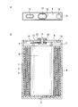
- the outer can was sealed, and the non-aqueous secondary battery having the structure shown in FIGS. 1A and 1B and the appearance shown in FIG. 2 was produced.
- This battery includes a cleavage vent for lowering the pressure when the internal pressure rises at the top of the can.
- FIG. 1A is a plan view
- FIG. 1B is a cross-sectional view
- the positive electrode 1 and the negative electrode 2 are spirally connected via a separator 3 as shown in FIG.
- the flat wound electrode body 6 is accommodated in a rectangular tube-shaped outer can 4 together with a non-aqueous electrolyte solution.
- a metal foil, an electrolytic solution, and the like as a current collector used for manufacturing the positive electrode 1 and the negative electrode 2 are not illustrated.
- the separator layers are not shown separately.
- the outer can 4 is made of an aluminum alloy and constitutes an outer casing of the battery.
- the outer can 4 also serves as a positive electrode terminal.
- the insulator 5 which consists of a polyethylene (PE) sheet
- a stainless steel terminal 11 is attached to a sealing lid plate 9 made of aluminum alloy for sealing the opening of the outer can 4 via an insulating packing 10 made of polypropylene (PP).
- a stainless steel lead plate 13 is attached via the body 12.
- the lid plate 9 is inserted into the opening of the outer can 4 and the joint between the two is welded to seal the opening of the outer can 4 and seal the inside of the battery.
- a non-aqueous electrolyte inlet 14 is provided in the lid plate 9, and a sealing member is inserted into the non-aqueous electrolyte inlet 14, for example, with a laser.
- the battery is hermetically sealed by welding or the like, so that the battery is sealed. Accordingly, in the batteries of FIGS. 1A, 1B and 2, the non-aqueous electrolyte inlet 14 is actually a non-aqueous electrolyte inlet and a sealing member. An electrolyte inlet 14 is shown.
- the lid plate 9 is provided with a cleavage vent 15 as a mechanism for discharging the internal gas to the outside when the temperature of the battery rises.
- the outer can 4 and the lid plate 9 function as a positive electrode terminal by directly welding the positive electrode lead body 7 to the lid plate 9, and the negative electrode lead body 8 is welded to the lead plate 13.
- the terminal 11 functions as a negative electrode terminal by conducting the negative electrode lead body 8 and the terminal 11 through the lead plate 13, but depending on the material of the outer can 4, the sign may be reversed. There is also.
- FIG. 2 is a perspective view showing the appearance of the battery shown in FIGS. 1A and 1B.
- FIG. 2 is shown for the purpose of showing that the battery is a square battery.
- FIG. 1 schematically shows a battery, and only specific members among the members constituting the battery are shown. Also in FIG. 1B, the central portion of the spirally wound electrode body 6 and the separator 3 are not indicated by hatching indicating a cross section.
- Example 1 shows the carbon coverage of the SiO x / carbon composite as the negative electrode active material, the I 510 / I 1343 intensity ratio of the Raman spectrum, and the half width of the Si (111) diffraction peak of X-ray diffraction of SiO x.
- a non-aqueous secondary battery was fabricated in the same manner as in Example 1 except for changing to.
- each battery was subjected to constant current-constant voltage charging (total charging time: 1 hour) at a constant current of 0.5 C (corresponding to 600 mA) and a constant voltage of 4.2 V at 25 ° C. It was stored in a constant temperature bath at 25 ° C. for 7 days. After storage, constant current discharge (discharge end voltage: 2.7 V) was performed at 1C.
- the carbon content in the SiO x / carbon composite as the negative electrode active material is 10 to 30% by mass, and in the Raman spectrum of the SiO x / carbon composite, the peak intensity at 510 cm ⁇ 1 derived from Si: I 510
- the peak intensity of 1343 cm ⁇ 1 derived from C: the intensity ratio with I 1343 : I 510 / I 1343 is set to 0.25 or less, and the X-ray diffraction peak of the (111) plane of the Si phase contained in the core material is half
- the nonaqueous secondary batteries of Examples 1 to 4 having a value width of less than 3.0 ° had a large initial discharge capacity, and an excellent capacity retention rate was obtained at storage at 25 ° C. and 45 ° C.
- the nonaqueous secondary batteries of Examples 1 to 3 in which the half width of the X-ray diffraction peak of the (111) plane of the Si phase contained in the core material is 0.5 ° or more have a high initial discharge capacity. became.
- Comparative Example 1 in which the carbon content in the SiO x / carbon composite is less than 10% by mass
- Comparative Example 2 in which the strength ratio: I 510 / I 1343 exceeds 0.25, and the Si phase contained in the core material
- Comparative Example 4 in which the half width of the X-ray diffraction peak of the (111) plane was 3.0 ° or more, the capacity retention rate was not good at 45 ° C. storage.
- the carbon content in the SiO x / carbon composite is preferably 10 to 30% by mass. Moreover, it turned out that it is preferable that intensity ratio: I510 / I1343 is 0.25 or less. Moreover, it is preferable that the half width of the X-ray diffraction peak of the (111) plane of the Si phase contained in the core material is less than 3.0 °, more preferably 0.5 ° or more and 2.5 ° or less. I understood.
- the non-aqueous secondary battery of the present invention has a high capacity and excellent battery characteristics, taking advantage of these characteristics, a power supply for a small and multifunctional portable device has been conventionally used. It can be preferably used for various applications to which known non-aqueous secondary batteries are applied.
Priority Applications (7)
| Application Number | Priority Date | Filing Date | Title |
|---|---|---|---|
| JP2012524958A JP5042400B2 (ja) | 2010-09-14 | 2011-09-12 | 非水二次電池 |
| US13/511,084 US8481212B2 (en) | 2010-09-14 | 2011-09-12 | Non-aqueous secondary battery |
| KR1020127015925A KR101181944B1 (ko) | 2010-09-14 | 2011-09-12 | 비수 이차 전지 |
| EP11825129.7A EP2618406B1 (en) | 2010-09-14 | 2011-09-12 | Nonaqueous secondary cell |
| CN201180012707.9A CN102792493B (zh) | 2010-09-14 | 2011-09-12 | 非水二次电池 |
| KR1020127017498A KR101741666B1 (ko) | 2010-09-14 | 2011-09-12 | 비수 이차 전지 |
| US13/915,405 US8859147B2 (en) | 2010-09-14 | 2013-06-11 | Non-aqueous secondary battery |
Applications Claiming Priority (2)
| Application Number | Priority Date | Filing Date | Title |
|---|---|---|---|
| JP2010205534 | 2010-09-14 | ||
| JP2010-205534 | 2010-09-14 |
Related Child Applications (2)
| Application Number | Title | Priority Date | Filing Date |
|---|---|---|---|
| US13/511,084 A-371-Of-International US8481212B2 (en) | 2010-09-14 | 2011-09-12 | Non-aqueous secondary battery |
| US13/915,405 Division US8859147B2 (en) | 2010-09-14 | 2013-06-11 | Non-aqueous secondary battery |
Publications (1)
| Publication Number | Publication Date |
|---|---|
| WO2012036127A1 true WO2012036127A1 (ja) | 2012-03-22 |
Family
ID=45831587
Family Applications (1)
| Application Number | Title | Priority Date | Filing Date |
|---|---|---|---|
| PCT/JP2011/070743 WO2012036127A1 (ja) | 2010-09-14 | 2011-09-12 | 非水二次電池 |
Country Status (6)
| Country | Link |
|---|---|
| US (2) | US8481212B2 (ko) |
| EP (1) | EP2618406B1 (ko) |
| JP (2) | JP5042400B2 (ko) |
| KR (2) | KR101741666B1 (ko) |
| CN (2) | CN102792493B (ko) |
| WO (1) | WO2012036127A1 (ko) |
Cited By (21)
| Publication number | Priority date | Publication date | Assignee | Title |
|---|---|---|---|---|
| JP2014022245A (ja) * | 2012-07-20 | 2014-02-03 | Hitachi Maxell Ltd | リチウムイオン二次電池およびその製造方法 |
| JP2014032802A (ja) * | 2012-08-02 | 2014-02-20 | Hitachi Maxell Ltd | 非水二次電池 |
| WO2014065417A1 (ja) * | 2012-10-26 | 2014-05-01 | 日立化成株式会社 | リチウムイオン二次電池用負極材料、リチウムイオン二次電池用負極及びリチウムイオン二次電池 |
| WO2014069117A1 (ja) * | 2012-10-30 | 2014-05-08 | 日立マクセル株式会社 | 非水二次電池用負極活物質および非水二次電池 |
| JP2014127317A (ja) * | 2012-12-26 | 2014-07-07 | Hitachi Ltd | 非水電解質二次電池の製造方法 |
| WO2014175354A1 (ja) * | 2013-04-26 | 2014-10-30 | 日産自動車株式会社 | 非水電解質二次電池 |
| WO2014175355A1 (ja) * | 2013-04-26 | 2014-10-30 | 日産自動車株式会社 | 非水電解質二次電池 |
| WO2015004834A1 (ja) * | 2013-07-10 | 2015-01-15 | 株式会社大阪チタニウムテクノロジーズ | リチウムイオン二次電池の負極材用粉末 |
| JP2015015101A (ja) * | 2013-07-03 | 2015-01-22 | 株式会社豊田自動織機 | リチウムイオン二次電池 |
| JP2015511374A (ja) * | 2012-12-21 | 2015-04-16 | エルジー・ケム・リミテッド | リチウム二次電池用負極材、その製造方法及びこれを含むリチウム二次電池 |
| JP2015106563A (ja) * | 2013-11-29 | 2015-06-08 | 深▲セン▼市貝特瑞新能源材料股▲ふん▼有限公司 | SIOx系複合負極材料、製造方法及び電池 |
| WO2015129188A1 (ja) * | 2014-02-28 | 2015-09-03 | 三洋電機株式会社 | 非水電解質二次電池 |
| JP2015210959A (ja) * | 2014-04-25 | 2015-11-24 | 日立化成株式会社 | リチウムイオン二次電池用負極材料、リチウムイオン二次電池用負極及びリチウムイオン二次電池 |
| JP2016110834A (ja) * | 2014-12-05 | 2016-06-20 | 株式会社東芝 | 非水電解質電池用活物質、非水電解質電池用電極、非水電解質二次電池および電池パック |
| JPWO2014050025A1 (ja) * | 2012-09-27 | 2016-08-22 | 三洋電機株式会社 | 非水電解質二次電池 |
| US9431652B2 (en) | 2012-12-21 | 2016-08-30 | Lg Chem, Ltd. | Anode active material for lithium secondary battery, method of preparing the same, and lithium secondary battery including the anode active material |
| JP2016533626A (ja) * | 2013-09-30 | 2016-10-27 | ルノー エス.ア.エス. | 黒鉛/ケイ素/炭素繊維複合材料を含有する電気エネルギー蓄電池用の電極 |
| WO2017073585A1 (ja) * | 2015-10-26 | 2017-05-04 | 株式会社日立製作所 | リチウムイオン二次電池およびリチウムイオン二次電池の製造方法 |
| WO2018143383A1 (ja) | 2017-02-03 | 2018-08-09 | 富士フイルム和光純薬株式会社 | リチウム電池電極用の結着剤組成物およびそれを用いた電極 |
| CN113422097A (zh) * | 2015-05-14 | 2021-09-21 | 艾诺维克斯公司 | 用于能量存储设备的纵向约束 |
| JP2021536102A (ja) * | 2019-05-28 | 2021-12-23 | 貝特瑞新材料集団股▲ふん▼有限公司Btr New Material Group Co., Ltd. | シリコン酸化物/炭素複合負極材料、その調製方法及びリチウムイオン電池 |
Families Citing this family (30)
| Publication number | Priority date | Publication date | Assignee | Title |
|---|---|---|---|---|
| US9570747B2 (en) * | 2011-12-16 | 2017-02-14 | Nec Corporation | Secondary battery |
| KR102480368B1 (ko) | 2012-08-16 | 2022-12-23 | 에노빅스 코오퍼레이션 | 3차원 배터리들을 위한 전극 구조들 |
| KR20200129176A (ko) | 2012-10-26 | 2020-11-17 | 쇼와덴코머티리얼즈가부시끼가이샤 | 리튬이온 2차 전지용 음극 재료, 리튬이온 2차 전지용 음극 및 리튬이온 2차 전지 |
| CN105074971B (zh) * | 2013-01-30 | 2017-03-29 | 三洋电机株式会社 | 非水电解质二次电池用负极活性物质、使用该负极活性物质的非水电解质二次电池用负极、以及使用该负极的非水电解质二次电池 |
| TWI504037B (zh) * | 2013-03-11 | 2015-10-11 | Hitachi Maxell | Lithium secondary battery pack, and the use of this electronic machine, charging system and charging method |
| WO2014142281A1 (ja) * | 2013-03-15 | 2014-09-18 | 日産自動車株式会社 | 非水電解質二次電池用正極およびこれを用いた非水電解質二次電池 |
| WO2014142280A1 (ja) * | 2013-03-15 | 2014-09-18 | 日産自動車株式会社 | 非水電解質二次電池 |
| KR102659783B1 (ko) | 2013-03-15 | 2024-04-22 | 에노빅스 코오퍼레이션 | 3차원 배터리들을 위한 분리기들 |
| WO2014178113A1 (ja) * | 2013-04-30 | 2014-11-06 | 日立オートモティブシステムズ株式会社 | リチウムイオン二次電池 |
| KR20200124329A (ko) | 2013-08-21 | 2020-11-02 | 신에쓰 가가꾸 고교 가부시끼가이샤 | 부극 활물질, 부극 활물질 재료, 부극 전극, 리튬 이온 이차 전지, 부극 활물질의 제조 방법, 및 리튬 이온 이차 전지의 제조 방법 |
| JP6432520B2 (ja) * | 2013-11-27 | 2018-12-05 | 三菱ケミカル株式会社 | 非水系二次電池負極用炭素材、それを用いた非水系二次電池用負極及び非水系二次電池 |
| JP6301142B2 (ja) * | 2014-01-31 | 2018-03-28 | 信越化学工業株式会社 | 非水電解質二次電池用負極材及び非水電解質二次電池用負極材の製造方法並びに非水電解質二次電池 |
| WO2015129187A1 (ja) * | 2014-02-28 | 2015-09-03 | 三洋電機株式会社 | 非水電解質二次電池 |
| JP5798209B2 (ja) * | 2014-03-28 | 2015-10-21 | 信越化学工業株式会社 | 非水電解質二次電池用負極材及びリチウムイオン二次電池 |
| JP6379655B2 (ja) * | 2014-05-15 | 2018-08-29 | Tdk株式会社 | リチウムイオン二次電池用負極活物質及びそれを有するリチウムイオン二次電池 |
| JP6686650B2 (ja) * | 2016-04-11 | 2020-04-22 | 株式会社村田製作所 | 二次電池、電池パック、電動車両、電力貯蔵システム、電動工具及び電子機器 |
| TWI739830B (zh) | 2016-05-13 | 2021-09-21 | 美商易諾維公司 | 用於三維電池之尺寸拘束件 |
| KR102104492B1 (ko) * | 2016-06-02 | 2020-04-24 | 주식회사 엘지화학 | 음극 활물질, 이의 제조방법, 이를 포함하는 음극 및 이를 포함하는 리튬이차전지 |
| US11063299B2 (en) | 2016-11-16 | 2021-07-13 | Enovix Corporation | Three-dimensional batteries with compressible cathodes |
| US10256507B1 (en) | 2017-11-15 | 2019-04-09 | Enovix Corporation | Constrained electrode assembly |
| WO2019099642A2 (en) | 2017-11-15 | 2019-05-23 | Enovix Corporation | Electrode assembly, secondary battery, and method of manufacture |
| JP6586197B1 (ja) * | 2018-06-01 | 2019-10-02 | 東洋インキScホールディングス株式会社 | カーボンナノチューブ、カーボンナノチューブ分散液およびその利用 |
| US11211639B2 (en) | 2018-08-06 | 2021-12-28 | Enovix Corporation | Electrode assembly manufacture and device |
| EP3951938A4 (en) * | 2019-11-28 | 2022-06-01 | Ningde Amperex Technology Ltd. | NEGATIVE ELECTRODE MATERIAL, ELECTROCHEMICAL DEVICE THEREOF AND ELECTRONIC DEVICE |
| JP7456291B2 (ja) * | 2020-05-29 | 2024-03-27 | 株式会社レゾナック | 炭素被覆複合材料、およびその用途 |
| JP2023547993A (ja) | 2020-09-18 | 2023-11-15 | エノビクス・コーポレイション | 電池に使用する電極の製造のための装置、システム、及び方法 |
| KR20230122050A (ko) | 2020-12-09 | 2023-08-22 | 에노빅스 코오퍼레이션 | 2차 배터리용 전극 조립체의 제조를 위한 방법 및 장치 |
| CN114068891B (zh) * | 2021-02-20 | 2022-11-15 | 贝特瑞新材料集团股份有限公司 | 硅碳复合负极材料及其制备方法、锂离子电池 |
| CN113809481B (zh) * | 2021-09-07 | 2023-01-24 | 厦门海辰储能科技股份有限公司 | 负极极柱盘、锂离子电池和锂电池的焊接方法 |
| CN115332483A (zh) * | 2022-10-11 | 2022-11-11 | 宁德新能源科技有限公司 | 负极极片、包含该负极极片的电化学装置及电子装置 |
Citations (11)
| Publication number | Priority date | Publication date | Assignee | Title |
|---|---|---|---|---|
| JPS5920971A (ja) | 1982-07-26 | 1984-02-02 | Sanyo Electric Co Ltd | 有機電解液二次電池 |
| JP2003308828A (ja) * | 2002-04-17 | 2003-10-31 | Hitachi Maxell Ltd | 角形非水二次電池 |
| JP2003331922A (ja) * | 2002-05-17 | 2003-11-21 | Sony Corp | 電 池 |
| JP2004047404A (ja) | 2002-05-17 | 2004-02-12 | Shin Etsu Chem Co Ltd | 導電性珪素複合体及びその製造方法並びに非水電解質二次電池用負極材 |
| JP2004146292A (ja) * | 2002-10-28 | 2004-05-20 | Japan Storage Battery Co Ltd | 非水電解質二次電池 |
| JP2004349164A (ja) * | 2003-05-23 | 2004-12-09 | Nec Corp | リチウムイオン二次電池用負極活物質、リチウムイオン二次電池用負極、およびリチウムイオン二次電池 |
| JP2005259697A (ja) | 2004-03-08 | 2005-09-22 | Samsung Sdi Co Ltd | リチウム二次電池用負極活物質、リチウム二次電池用負極活物質、およびリチウム二次電池 |
| JP2008210618A (ja) | 2007-02-26 | 2008-09-11 | Hitachi Maxell Ltd | 非水電解質二次電池 |
| JP2009164104A (ja) * | 2007-09-06 | 2009-07-23 | Canon Inc | 負極用電極材料、その製造方法ならびに該材料を用いた電極構造体及び蓄電デバイス |
| JP2009301935A (ja) * | 2008-06-16 | 2009-12-24 | Shin-Etsu Chemical Co Ltd | 非水電解質二次電池用負極材及びその製造方法、ならびにリチウムイオン二次電池及び電気化学キャパシタ |
| JP2011100745A (ja) * | 2011-01-26 | 2011-05-19 | Gs Yuasa Corp | 非水電解質二次電池 |
Family Cites Families (29)
| Publication number | Priority date | Publication date | Assignee | Title |
|---|---|---|---|---|
| JP3639376B2 (ja) * | 1996-03-15 | 2005-04-20 | 日立マクセル株式会社 | 有機電解液二次電池 |
| JP2000243396A (ja) * | 1999-02-23 | 2000-09-08 | Hitachi Ltd | リチウム二次電池とその製造方法及びその負極材並びに電気機器 |
| JP2004063433A (ja) * | 2001-12-26 | 2004-02-26 | Shin Etsu Chem Co Ltd | 導電性酸化珪素粉末、その製造方法及び該粉末を用いた非水電解質二次電池用負極材 |
| WO2003096449A1 (fr) | 2002-05-08 | 2003-11-20 | Japan Storage Battery Co., Ltd. | Pile secondaire a electrolyte non aqueux |
| TWI278429B (en) * | 2002-05-17 | 2007-04-11 | Shinetsu Chemical Co | Conductive silicon composite, preparation thereof, and negative electrode material for non-aqueous electrolyte secondary cell |
| JP4635409B2 (ja) * | 2003-04-14 | 2011-02-23 | 株式会社Gsユアサ | 非水電解質電池 |
| JP4671589B2 (ja) * | 2003-07-15 | 2011-04-20 | 三星エスディアイ株式会社 | リチウム二次電池用電解質及びリチウム二次電池 |
| JP5094013B2 (ja) * | 2004-12-10 | 2012-12-12 | キヤノン株式会社 | リチウム二次電池用の電極構造体及び該電極構造体を有する二次電池 |
| JP4707426B2 (ja) * | 2005-03-23 | 2011-06-22 | 三洋電機株式会社 | 非水電解質二次電池 |
| JP4854289B2 (ja) * | 2005-12-14 | 2012-01-18 | 日立マクセルエナジー株式会社 | 非水電解液二次電池 |
| TWI341605B (en) * | 2006-02-15 | 2011-05-01 | Lg Chemical Ltd | Non-aqueous electrolyte and electrochemical device with an improved safety |
| JP5094084B2 (ja) * | 2006-09-28 | 2012-12-12 | 三洋電機株式会社 | 非水電解質二次電池 |
| KR100851969B1 (ko) | 2007-01-05 | 2008-08-12 | 삼성에스디아이 주식회사 | 음극 활물질, 그 제조 방법 및 이를 채용한 음극과 리튬전지 |
| KR101451801B1 (ko) * | 2007-02-14 | 2014-10-17 | 삼성에스디아이 주식회사 | 음극 활물질, 그 제조 방법 및 이를 채용한 음극과 리튬전지 |
| KR20090111342A (ko) * | 2007-05-10 | 2009-10-26 | 히다치 막셀 가부시키가이샤 | 전기 화학 소자 및 그 제조방법 |
| JP2009032682A (ja) * | 2007-06-28 | 2009-02-12 | Hitachi Maxell Ltd | リチウムイオン二次電池 |
| KR20100051708A (ko) * | 2007-11-12 | 2010-05-17 | 히다치 막셀 가부시키가이샤 | 비수 2차 전지용 전극 및 그것을 사용한 비수 2차 전지, 및 전극의 제조방법 |
| JP5213103B2 (ja) * | 2007-12-19 | 2013-06-19 | 日立マクセル株式会社 | 非水電解質二次電池用正極、非水電解質二次電池および電子機器 |
| JP2009158415A (ja) * | 2007-12-27 | 2009-07-16 | Mitsui Mining & Smelting Co Ltd | 非水電解液二次電池用正極活物質及びそれを有する非水電解液二次電池 |
| KR101111710B1 (ko) * | 2008-01-29 | 2012-03-13 | 히다치 막셀 가부시키가이샤 | 절연층 형성용 슬러리, 전기화학소자용 세퍼레이터 및 그 제조방법, 및 전기화학소자 |
| JP5196149B2 (ja) * | 2008-02-07 | 2013-05-15 | 信越化学工業株式会社 | 非水電解質二次電池用負極材及びその製造方法並びにリチウムイオン二次電池及び電気化学キャパシタ |
| JP5297109B2 (ja) | 2008-03-12 | 2013-09-25 | 日立マクセル株式会社 | 非水電解質二次電池 |
| JP2009224097A (ja) * | 2008-03-14 | 2009-10-01 | Panasonic Corp | 非水電解質二次電池 |
| KR101406013B1 (ko) * | 2008-03-17 | 2014-06-11 | 신에쓰 가가꾸 고교 가부시끼가이샤 | 비수 전해질 2차 전지용 부극재 및 그것의 제조 방법, 및 비수 전해질 2차 전지용 부극 및 비수 전해질 2차 전지 |
| JP4844764B2 (ja) * | 2008-03-17 | 2011-12-28 | 信越化学工業株式会社 | 非水電解質二次電池負極及びそれを用いた非水電解質二次電池 |
| JP4986166B2 (ja) | 2008-05-08 | 2012-07-25 | 日立マクセルエナジー株式会社 | リチウム二次電池 |
| JP2010034024A (ja) * | 2008-06-25 | 2010-02-12 | Hitachi Maxell Ltd | リチウムイオン二次電池 |
| JP2010067359A (ja) | 2008-09-08 | 2010-03-25 | Teijin Ltd | 非水電解質電池セパレータ及びそれを用いた非水電解質二次電池 |
| JP2010092830A (ja) * | 2008-09-11 | 2010-04-22 | Sanyo Electric Co Ltd | 非水電解質二次電池 |
-
2011
- 2011-09-12 US US13/511,084 patent/US8481212B2/en active Active
- 2011-09-12 CN CN201180012707.9A patent/CN102792493B/zh active Active
- 2011-09-12 WO PCT/JP2011/070743 patent/WO2012036127A1/ja active Application Filing
- 2011-09-12 KR KR1020127017498A patent/KR101741666B1/ko active IP Right Grant
- 2011-09-12 EP EP11825129.7A patent/EP2618406B1/en active Active
- 2011-09-12 CN CN201310466861.4A patent/CN103560225B/zh active Active
- 2011-09-12 JP JP2012524958A patent/JP5042400B2/ja active Active
- 2011-09-12 KR KR1020127015925A patent/KR101181944B1/ko active IP Right Grant
-
2012
- 2012-07-10 JP JP2012154707A patent/JP5756063B2/ja active Active
-
2013
- 2013-06-11 US US13/915,405 patent/US8859147B2/en active Active
Patent Citations (11)
| Publication number | Priority date | Publication date | Assignee | Title |
|---|---|---|---|---|
| JPS5920971A (ja) | 1982-07-26 | 1984-02-02 | Sanyo Electric Co Ltd | 有機電解液二次電池 |
| JP2003308828A (ja) * | 2002-04-17 | 2003-10-31 | Hitachi Maxell Ltd | 角形非水二次電池 |
| JP2003331922A (ja) * | 2002-05-17 | 2003-11-21 | Sony Corp | 電 池 |
| JP2004047404A (ja) | 2002-05-17 | 2004-02-12 | Shin Etsu Chem Co Ltd | 導電性珪素複合体及びその製造方法並びに非水電解質二次電池用負極材 |
| JP2004146292A (ja) * | 2002-10-28 | 2004-05-20 | Japan Storage Battery Co Ltd | 非水電解質二次電池 |
| JP2004349164A (ja) * | 2003-05-23 | 2004-12-09 | Nec Corp | リチウムイオン二次電池用負極活物質、リチウムイオン二次電池用負極、およびリチウムイオン二次電池 |
| JP2005259697A (ja) | 2004-03-08 | 2005-09-22 | Samsung Sdi Co Ltd | リチウム二次電池用負極活物質、リチウム二次電池用負極活物質、およびリチウム二次電池 |
| JP2008210618A (ja) | 2007-02-26 | 2008-09-11 | Hitachi Maxell Ltd | 非水電解質二次電池 |
| JP2009164104A (ja) * | 2007-09-06 | 2009-07-23 | Canon Inc | 負極用電極材料、その製造方法ならびに該材料を用いた電極構造体及び蓄電デバイス |
| JP2009301935A (ja) * | 2008-06-16 | 2009-12-24 | Shin-Etsu Chemical Co Ltd | 非水電解質二次電池用負極材及びその製造方法、ならびにリチウムイオン二次電池及び電気化学キャパシタ |
| JP2011100745A (ja) * | 2011-01-26 | 2011-05-19 | Gs Yuasa Corp | 非水電解質二次電池 |
Non-Patent Citations (1)
| Title |
|---|
| See also references of EP2618406A4 |
Cited By (32)
| Publication number | Priority date | Publication date | Assignee | Title |
|---|---|---|---|---|
| JP2014022245A (ja) * | 2012-07-20 | 2014-02-03 | Hitachi Maxell Ltd | リチウムイオン二次電池およびその製造方法 |
| JP2014032802A (ja) * | 2012-08-02 | 2014-02-20 | Hitachi Maxell Ltd | 非水二次電池 |
| JPWO2014050025A1 (ja) * | 2012-09-27 | 2016-08-22 | 三洋電機株式会社 | 非水電解質二次電池 |
| WO2014065417A1 (ja) * | 2012-10-26 | 2014-05-01 | 日立化成株式会社 | リチウムイオン二次電池用負極材料、リチウムイオン二次電池用負極及びリチウムイオン二次電池 |
| CN104737337A (zh) * | 2012-10-26 | 2015-06-24 | 日立化成株式会社 | 锂离子二次电池用负极材料、锂离子二次电池用负极和锂离子二次电池 |
| WO2014069117A1 (ja) * | 2012-10-30 | 2014-05-08 | 日立マクセル株式会社 | 非水二次電池用負極活物質および非水二次電池 |
| JP2015511374A (ja) * | 2012-12-21 | 2015-04-16 | エルジー・ケム・リミテッド | リチウム二次電池用負極材、その製造方法及びこれを含むリチウム二次電池 |
| US9431652B2 (en) | 2012-12-21 | 2016-08-30 | Lg Chem, Ltd. | Anode active material for lithium secondary battery, method of preparing the same, and lithium secondary battery including the anode active material |
| JP2014127317A (ja) * | 2012-12-26 | 2014-07-07 | Hitachi Ltd | 非水電解質二次電池の製造方法 |
| US10033033B2 (en) | 2013-04-26 | 2018-07-24 | Nissan Motor Co., Ltd. | Non-aqueous electrolyte secondary battery |
| WO2014175355A1 (ja) * | 2013-04-26 | 2014-10-30 | 日産自動車株式会社 | 非水電解質二次電池 |
| WO2014175354A1 (ja) * | 2013-04-26 | 2014-10-30 | 日産自動車株式会社 | 非水電解質二次電池 |
| JPWO2014175354A1 (ja) * | 2013-04-26 | 2017-02-23 | 日産自動車株式会社 | 非水電解質二次電池 |
| JP6036999B2 (ja) * | 2013-04-26 | 2016-11-30 | 日産自動車株式会社 | 非水電解質二次電池 |
| JP2015015101A (ja) * | 2013-07-03 | 2015-01-22 | 株式会社豊田自動織機 | リチウムイオン二次電池 |
| WO2015004834A1 (ja) * | 2013-07-10 | 2015-01-15 | 株式会社大阪チタニウムテクノロジーズ | リチウムイオン二次電池の負極材用粉末 |
| JP5996802B2 (ja) * | 2013-07-10 | 2016-09-21 | 株式会社大阪チタニウムテクノロジーズ | リチウムイオン二次電池の負極材用粉末 |
| JP2016533626A (ja) * | 2013-09-30 | 2016-10-27 | ルノー エス.ア.エス. | 黒鉛/ケイ素/炭素繊維複合材料を含有する電気エネルギー蓄電池用の電極 |
| JP2015106563A (ja) * | 2013-11-29 | 2015-06-08 | 深▲セン▼市貝特瑞新能源材料股▲ふん▼有限公司 | SIOx系複合負極材料、製造方法及び電池 |
| WO2015129188A1 (ja) * | 2014-02-28 | 2015-09-03 | 三洋電機株式会社 | 非水電解質二次電池 |
| JPWO2015129188A1 (ja) * | 2014-02-28 | 2017-03-30 | 三洋電機株式会社 | 非水電解質二次電池 |
| US10193183B2 (en) | 2014-02-28 | 2019-01-29 | Sanyo Electric Co., Ltd. | Nonaqueous electrolyte secondary batteries |
| JP2015210959A (ja) * | 2014-04-25 | 2015-11-24 | 日立化成株式会社 | リチウムイオン二次電池用負極材料、リチウムイオン二次電池用負極及びリチウムイオン二次電池 |
| JP2016110834A (ja) * | 2014-12-05 | 2016-06-20 | 株式会社東芝 | 非水電解質電池用活物質、非水電解質電池用電極、非水電解質二次電池および電池パック |
| US10468669B2 (en) | 2014-12-05 | 2019-11-05 | Kabushiki Kaisha Toshiba | Active material for nonaqueous electrolyte battery, electrode for nonaqueous electrolyte battery, nonaqueous electrolyte secondary battery and battery pack |
| CN113422097A (zh) * | 2015-05-14 | 2021-09-21 | 艾诺维克斯公司 | 用于能量存储设备的纵向约束 |
| US11894512B2 (en) | 2015-05-14 | 2024-02-06 | Enovix Corporation | Longitudinal constraints for energy storage devices |
| WO2017073585A1 (ja) * | 2015-10-26 | 2017-05-04 | 株式会社日立製作所 | リチウムイオン二次電池およびリチウムイオン二次電池の製造方法 |
| WO2018143383A1 (ja) | 2017-02-03 | 2018-08-09 | 富士フイルム和光純薬株式会社 | リチウム電池電極用の結着剤組成物およびそれを用いた電極 |
| KR20190110521A (ko) | 2017-02-03 | 2019-09-30 | 후지필름 와코 준야쿠 가부시키가이샤 | 리튬 전지 전극용의 결착제 조성물 및 그것을 이용한 전극 |
| JP2021536102A (ja) * | 2019-05-28 | 2021-12-23 | 貝特瑞新材料集団股▲ふん▼有限公司Btr New Material Group Co., Ltd. | シリコン酸化物/炭素複合負極材料、その調製方法及びリチウムイオン電池 |
| JP7185764B2 (ja) | 2019-05-28 | 2022-12-07 | 貝特瑞新材料集団股▲ふん▼有限公司 | シリコン酸化物/炭素複合負極材料、その調製方法及びリチウムイオン電池 |
Also Published As
| Publication number | Publication date |
|---|---|
| US8481212B2 (en) | 2013-07-09 |
| JPWO2012036127A1 (ja) | 2014-02-03 |
| CN103560225A (zh) | 2014-02-05 |
| US20120288742A1 (en) | 2012-11-15 |
| JP5042400B2 (ja) | 2012-10-03 |
| KR101741666B1 (ko) | 2017-05-30 |
| US8859147B2 (en) | 2014-10-14 |
| CN102792493A (zh) | 2012-11-21 |
| JP2012227154A (ja) | 2012-11-15 |
| KR101181944B1 (ko) | 2012-09-11 |
| EP2618406B1 (en) | 2016-06-22 |
| CN102792493B (zh) | 2015-03-11 |
| KR20130040767A (ko) | 2013-04-24 |
| EP2618406A1 (en) | 2013-07-24 |
| EP2618406A4 (en) | 2014-03-05 |
| JP5756063B2 (ja) | 2015-07-29 |
| KR20120080256A (ko) | 2012-07-16 |
| CN103560225B (zh) | 2016-08-17 |
| US20130273439A1 (en) | 2013-10-17 |
Similar Documents
| Publication | Publication Date | Title |
|---|---|---|
| JP5756063B2 (ja) | 非水二次電池 | |
| JP4868556B2 (ja) | リチウム二次電池 | |
| JP6253411B2 (ja) | リチウム二次電池 | |
| JP2011243558A (ja) | リチウム二次電池用正極およびリチウム二次電池 | |
| JP5872055B2 (ja) | リチウム二次電池パック、並びにそれを用いた電子機器、充電システム及び充電方法 | |
| JP5341280B2 (ja) | リチウム二次電池パック、並びにそれを用いた電子機器、充電システム及び充電方法 | |
| JP5489353B2 (ja) | 非水電解液二次電池 | |
| JP5945197B2 (ja) | 非水電解液二次電池 | |
| WO2013133361A1 (ja) | リチウム二次電池パック、並びにそれを用いた電子機器、充電システムおよび充電方法 | |
| JP2012084426A (ja) | 非水電解質二次電池 | |
| WO2014069117A1 (ja) | 非水二次電池用負極活物質および非水二次電池 | |
| JP5566825B2 (ja) | リチウム二次電池 | |
| KR20140041312A (ko) | 리튬 이온 이차 전지용 정극, 리튬 이온 이차 전지 및 전지 시스템 | |
| JP5658122B2 (ja) | リチウム二次電池 | |
| JP2013118068A (ja) | リチウム二次電池 | |
| JP5785653B2 (ja) | リチウム二次電池 | |
| JP2013030398A (ja) | 負極材料、その製造方法、非水電解質二次電池用負極および非水電解質二次電池 |
Legal Events
| Date | Code | Title | Description |
|---|---|---|---|
| WWE | Wipo information: entry into national phase |
Ref document number: 201180012707.9 Country of ref document: CN |
|
| WWE | Wipo information: entry into national phase |
Ref document number: 2012524958 Country of ref document: JP |
|
| 121 | Ep: the epo has been informed by wipo that ep was designated in this application |
Ref document number: 11825129 Country of ref document: EP Kind code of ref document: A1 |
|
| WWE | Wipo information: entry into national phase |
Ref document number: 13511084 Country of ref document: US |
|
| ENP | Entry into the national phase |
Ref document number: 20127015925 Country of ref document: KR Kind code of ref document: A |
|
| WWE | Wipo information: entry into national phase |
Ref document number: 2011825129 Country of ref document: EP |
|
| NENP | Non-entry into the national phase |
Ref country code: DE |