WO2012014375A1 - ガス供給装置用流量制御器の校正方法及び流量計測方法 - Google Patents
ガス供給装置用流量制御器の校正方法及び流量計測方法 Download PDFInfo
- Publication number
- WO2012014375A1 WO2012014375A1 PCT/JP2011/003679 JP2011003679W WO2012014375A1 WO 2012014375 A1 WO2012014375 A1 WO 2012014375A1 JP 2011003679 W JP2011003679 W JP 2011003679W WO 2012014375 A1 WO2012014375 A1 WO 2012014375A1
- Authority
- WO
- WIPO (PCT)
- Prior art keywords
- gas
- flow rate
- tank
- valve
- flow
- Prior art date
Links
Images


Classifications
-
- G—PHYSICS
- G01—MEASURING; TESTING
- G01F—MEASURING VOLUME, VOLUME FLOW, MASS FLOW OR LIQUID LEVEL; METERING BY VOLUME
- G01F25/00—Testing or calibration of apparatus for measuring volume, volume flow or liquid level or for metering by volume
-
- G—PHYSICS
- G01—MEASURING; TESTING
- G01F—MEASURING VOLUME, VOLUME FLOW, MASS FLOW OR LIQUID LEVEL; METERING BY VOLUME
- G01F7/00—Volume-flow measuring devices with two or more measuring ranges; Compound meters
- G01F7/005—Volume-flow measuring devices with two or more measuring ranges; Compound meters by measuring pressure or differential pressure, created by the use of flow constriction
-
- G—PHYSICS
- G01—MEASURING; TESTING
- G01F—MEASURING VOLUME, VOLUME FLOW, MASS FLOW OR LIQUID LEVEL; METERING BY VOLUME
- G01F1/00—Measuring the volume flow or mass flow of fluid or fluent solid material wherein the fluid passes through a meter in a continuous flow
- G01F1/05—Measuring the volume flow or mass flow of fluid or fluent solid material wherein the fluid passes through a meter in a continuous flow by using mechanical effects
- G01F1/34—Measuring the volume flow or mass flow of fluid or fluent solid material wherein the fluid passes through a meter in a continuous flow by using mechanical effects by measuring pressure or differential pressure
-
- G—PHYSICS
- G01—MEASURING; TESTING
- G01F—MEASURING VOLUME, VOLUME FLOW, MASS FLOW OR LIQUID LEVEL; METERING BY VOLUME
- G01F15/00—Details of, or accessories for, apparatus of groups G01F1/00 - G01F13/00 insofar as such details or appliances are not adapted to particular types of such apparatus
- G01F15/001—Means for regulating or setting the meter for a predetermined quantity
- G01F15/002—Means for regulating or setting the meter for a predetermined quantity for gases
-
- G—PHYSICS
- G01—MEASURING; TESTING
- G01F—MEASURING VOLUME, VOLUME FLOW, MASS FLOW OR LIQUID LEVEL; METERING BY VOLUME
- G01F15/00—Details of, or accessories for, apparatus of groups G01F1/00 - G01F13/00 insofar as such details or appliances are not adapted to particular types of such apparatus
- G01F15/005—Valves
-
- G—PHYSICS
- G01—MEASURING; TESTING
- G01F—MEASURING VOLUME, VOLUME FLOW, MASS FLOW OR LIQUID LEVEL; METERING BY VOLUME
- G01F25/00—Testing or calibration of apparatus for measuring volume, volume flow or liquid level or for metering by volume
- G01F25/10—Testing or calibration of apparatus for measuring volume, volume flow or liquid level or for metering by volume of flowmeters
- G01F25/15—Testing or calibration of apparatus for measuring volume, volume flow or liquid level or for metering by volume of flowmeters specially adapted for gas meters
-
- G—PHYSICS
- G05—CONTROLLING; REGULATING
- G05D—SYSTEMS FOR CONTROLLING OR REGULATING NON-ELECTRIC VARIABLES
- G05D7/00—Control of flow
- G05D7/06—Control of flow characterised by the use of electric means
-
- G—PHYSICS
- G05—CONTROLLING; REGULATING
- G05D—SYSTEMS FOR CONTROLLING OR REGULATING NON-ELECTRIC VARIABLES
- G05D7/00—Control of flow
- G05D7/06—Control of flow characterised by the use of electric means
- G05D7/0617—Control of flow characterised by the use of electric means specially adapted for fluid materials
- G05D7/0629—Control of flow characterised by the use of electric means specially adapted for fluid materials characterised by the type of regulator means
- G05D7/0635—Control of flow characterised by the use of electric means specially adapted for fluid materials characterised by the type of regulator means by action on throttling means
- G05D7/0641—Control of flow characterised by the use of electric means specially adapted for fluid materials characterised by the type of regulator means by action on throttling means using a plurality of throttling means
- G05D7/0652—Control of flow characterised by the use of electric means specially adapted for fluid materials characterised by the type of regulator means by action on throttling means using a plurality of throttling means the plurality of throttling means being arranged in parallel
-
- Y—GENERAL TAGGING OF NEW TECHNOLOGICAL DEVELOPMENTS; GENERAL TAGGING OF CROSS-SECTIONAL TECHNOLOGIES SPANNING OVER SEVERAL SECTIONS OF THE IPC; TECHNICAL SUBJECTS COVERED BY FORMER USPC CROSS-REFERENCE ART COLLECTIONS [XRACs] AND DIGESTS
- Y10—TECHNICAL SUBJECTS COVERED BY FORMER USPC
- Y10T—TECHNICAL SUBJECTS COVERED BY FORMER US CLASSIFICATION
- Y10T137/00—Fluid handling
- Y10T137/0318—Processes
- Y10T137/0324—With control of flow by a condition or characteristic of a fluid
Definitions
- the present invention relates to an improvement of a flow rate controller calibration method and a flow rate measurement method of a gas supply device used in a semiconductor manufacturing device, a chemical manufacturing device, etc., and more accurate flow rate calibration and flow rate measurement can be performed in a short time.
- the present invention relates to a calibration method and a flow rate measurement method for a flow rate controller for a gas supply device that can be quickly performed.
- a gas supply apparatus such as a semiconductor manufacturing apparatus is generally configured to supply various types of gas to a gas usage target such as a process chamber, and the flow rate is controlled by a flow rate controller provided for each type of supply gas. The gas is supplied to the gas usage target.
- the flow rate calibration and the flow rate measurement of each flow rate controller are generally performed at appropriate time intervals by the build-up method (or the pressure rise rate (ROR) method), and the set flow rate and build-up of the flow rate controller are performed.
- a flow rate calibration of a flow rate controller is performed by comparing with an actual control flow rate measured by a method or the like, or a flow rate measurement for obtaining a flow rate from a measured value by a build-up method or the like is performed.
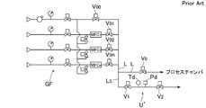
- FIG. 12 and 13 show an example of a conventional calibration method of the flow controller for the gas supply device. That is, at the calibration method of FIG. 12, first, the flow rate consisting of a build-up tank BT and the inlet shutoff valve V 1 and the outlet on-off valve V 2 and the pressure detector Pd and gas temperature detectors Td constant internal volume
- the calibration unit U is connected to the gas supply path L in a branched manner.
- the on-off valves Vo 2 , Von, Vo are closed, the on-off valves Vo 1 , V 1, and V 2 are opened, and the tank BT Gas is circulated to the inside, and the pressure detection value P 1 and the temperature detection value T 1 at time t 1 after the on-off valves V 1 and V 2 are opened or after the on-off valve V 2 is closed are measured.
- the on-off valve V 2 is closed, and the pressure detection value P 2 and the temperature detection value T 2 after ⁇ t seconds or after ⁇ t seconds from the time t 1 are measured.
- the flow rate calculation formula calculates the build-up flow rate into the tank BT assuming that the gas is an ideal gas, V is the internal volume of the build-up tank BT, R is a gas constant, and T is the tank BT. The gas temperature inside.
- the flow rate calibration unit U ′ in which the buildup tank is omitted is connected to the gas supply line L in a branched manner.
- the on-off valves Vo, Vo 0 , Vo 2 and Von are closed, and the on-off valves Vo 1 , V 1 and V 2 are opened.
- a gas having a set flow rate is supplied from the flow rate controller MFC 1 to the flow rate calibration unit U ′, and then the on-off valve V 2 is closed.
- the on-off valve V 2 After closure of the on-off valve V 2, performs a first measurement when the pressure detected value of the pressure detector Pd becomes P 1, the pressure P 1, to measure the temperature T 1.
- the second measurement is performed when the pressure detection value of the pressure detector P reaches P 2 (or when the set time t seconds elapses), and the pressure P 2 and the temperature T 2 are measured.
- FIG. 13 has the same technical idea as that of the present invention in that the flow rate Q is obtained from the inflow mass dG.
- the method of FIG. (Timing) determinants are different. That is, in the present invention, after the gas build-up, the second measurement is performed after the gas temperature T 2 in the build-up tank BT becomes a constant value near the gas temperature T 1 before the build-up.
- the method of FIG. 12 basically differs in technical idea.
- the method using the build-up tank BT shown in FIG. 12 described above detects the gas temperature in the tank BT more accurately than before by reducing the heat capacity by thinning the thermocouple as the temperature detector Td. It is coming to be able to do it.
- the measured value of the gas temperature in the tank BT varies greatly depending on the mounting position of the temperature detector Td to the build-up tank BT, and (2) the gas temperature during the increase of the gas pressure in the tank. T actually fluctuates greatly and does not reach a constant temperature T.
- (3) When the temperature change of the outside air is large, the gas temperature during pressure detection changes and the fluctuation of the temperature detection value T increases. There is a problem that the reliability of the calculated value of the flow rate Q is low even if the gas is close to the ideal gas.
- the outlet of the flow rate controller MFC 1 and the downstream side open / close valve of the flow rate calibration unit U ′ are provided without providing the flow rate calibration unit U ′ with the build-up tank BT whose internal volume is known.
- the flow rate is calculated assuming that the internal volume V of the pipe line between V 2 corresponds to the internal volume of the build-up tank.
- the flow path volume V must be calculated, and not only is the flow rate calibration of the flow rate controller MFC troublesome, but the calculated value of the control flow rate is set to the temperature T and The measurement error related to the pressure P and the time t and the measurement error related to the flow path volume V are combined to cause a problem that the calculation accuracy of the control flow rate is greatly reduced.
- the present invention relates to the above-mentioned problems in the flow rate controller calibration method and flow rate measurement method by the conventional build-up or ROR method, that is, (1) using a build-up tank whose internal volume is known in advance, In the method of calibrating the control flow rate based on the pressure increase rate ⁇ P / ⁇ t and the time ⁇ t, the calculation error of the flow rate due to the fluctuation of the gas temperature during the pressure increase is unavoidable, and (2) In this method, a steady flow rate gas is supplied into a flow channel having an internal volume V, and a flow rate Q is calculated by obtaining a difference ⁇ G in the mass of gas flowing into the flow channel V during a certain time interval ⁇ t. First, it is necessary to obtain the flow path volume V by some method. Compared to the case where the build-up tank BT having a known internal volume is used, it takes time to calculate the flow path volume V. There is a problem of passing.
- the inventors of the present application based on the flow rate calibration method of the flow rate controller by the conventional build-up (or ROR) method, (1) the flow rate calculation based on the labor involved in the calculation of the pipe volume V and the calculation error of the volume V In order to reduce the error in the value, it is inevitable to use a build-up tank having an appropriate capacity with a known internal volume V, and (2) the build-up tank inlet side on-off valve is suddenly increased after the pressure rise due to build-up. It was found that the gas temperature in the tank BT suddenly returned to a constant temperature close to room temperature by closing.
- the inventors of the present application calculate the number of moles of gas flowing into the build-up tank BT (inflow mass G) from the gas pressure and gas temperature before and after build-up based on the above knowledge, and can be opened and closed at high speed.
- an on-off valve for example, a solenoid valve
- the build-up time and the time to close the inlet-side on-off valve of the build-up tank BT after completion of the build-up are accurately controlled, and the gas temperature in the tank after build-up is built up.
- the second measurement is performed when the gas temperature in the previous tank is approached, so that it is possible to calibrate the flow controller with higher accuracy, and many flow rate calibration tests are performed based on this idea. did.
- the invention of the calibration method of the present application was invented based on the test result of the flow rate calibration test, and the invention of claim 1 is capable of switching a plurality of types of gas through each flow controller to the gas use location.
- the flow controller calibration unit 5 consisting of a gas pressure detector Pd and gas temperature detectors Td while connected to branched, connects the outlet side switching valve V 2 of the flow controller calibration unit 5 to the evacuation device first, the outlet-side valve Vo 1 ⁇ Vo n and the outlet side switching valve V 2 and the inlet side of the calibration unit 5 while closing the inlet on-off valve V 0 which gas usages of the flow controller of the flow control device Open Opening valve V 1, then open only the outlet side switching valve of the calibration flow rate controller allowed to flow into a flow rate for the gas to the calibration unit 5,
- the invention of the flow rate measuring method of the present application is a method for measuring a flow rate of a flow rate controller that controls a fluid flowing from a fluid supply source, and a buildup tank BT having an internal volume V downstream of the flow rate controller and an inlet of the tank BT.
- the second time measurement by the flow controller calibration unit after the built-up completion (i.e., the closing point t 1 the inlet-side valve V 1) without the, the inlet-side valve V 1
- the operation is performed at a time t 2 after a certain time from the closing point t 1 .
- the gas temperature T 2 in the build-up tank BT reaches a temperature very close to the gas temperature To (that is, the room temperature) in the tank before the build-up.
- the calculation is performed assuming that there is no large difference between the gas temperatures T 0 and T 2 during the first measurement and the second measurement, and the temperature T during the pressure increase is constant. Compared to the build-up method, more accurate flow rate calibration can be performed.
- the gas supply channel is used as in the case of the method for obtaining the calculated flow rate from the data of the first and second measurements. It is not necessary to measure the internal volume of the material in advance or simultaneously. As a result, flow rate calibration can be performed very easily, and even if the internal volume of the gas supply path changes due to a change in the configuration of the gas supply device, the flow rate controller can be quickly calibrated without any effect. I can do it.
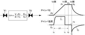
- FIG. 3 schematically shows the result of FIG. 2.
- D is a diagram showing the relationship between the set flow rate and the error% R.E.
- the set flow rate and error% R.R Of the flow rate controller in the second embodiment using the build-up tank with an internal volume of 120.36 cc of the present invention.
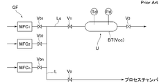
- FIG. 1 is an explanatory diagram of a first embodiment of a calibration method for a flow rate controller for a gas supply device according to the present invention, and shows a case where flow rate calibration of a flow rate controller MFC provided in the gas supply device GF is performed.
- GF is a gas supply device
- MFC 1 to MFCn are flow controllers
- Go to Gn are supply gases
- L to Ln and Ls are gas supply paths
- V 00 to V 0n are on-off valves
- V 0 is an on-off valve.
- V 1 and V 2 are on-off valves
- CH is a process chamber
- VP is a vacuum pump
- Td is a temperature detector
- Pd is a pressure detector
- BT is a build-up tank
- 1 is a pressure regulator
- 2 is a pressure gauge
- 5 is a flow controller calibration unit
- CP is the arithmetic control unit
- the gas supply passage from the gas supply device GF L it is supplied switched predetermined gas to the process chamber CH through valve V 0.
- the flow rate controller calibration unit 5 includes a build-up tank BT, an inlet side on-off valve V 1 , an outlet side on-off valve V 2 , a pressure detector Pd and a temperature detector Td provided in the tank BT, and the like.
- a branch is connected to the gas supply flow path L via the path Ls.
- a control signal such as on-off valve V 1 and closing valve V 2 is output to the calculation control unit CP, later
- the inventor of the present application uses the flow rate controller calibration unit 5 in FIG. 1 to close the inlet-side on-off valve V1 after the build-up causes the gas temperature in the tank BT whose gas pressure has been raised by build-up. We investigated how it changed.
- a standard flow rate regulator is attached in place of the flow rate controller MFC 1, and the on-off valves V 00 , V 02 , V 0n , V 0 are first closed, and the on-off valves V 1 , V 2 is opened and N 2 gas is allowed to flow at a flow rate of 500 sccm for a certain period of time.
- the outlet side on-off valve V 2 is closed and build-up is performed for 10 seconds. It was carried out, and it closes the inlet-side valve V 1 immediately thereafter, and observe the change state of the gas temperature in the build-up BT.
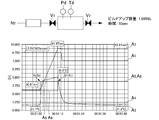
- the flow rate controller uses a Fujikin capacity of 100 sccm and 1 SLM, and the internal volume V of the build-up BT is set to 1.0996 L (known).
- the gas flow rate (N 2 ) is set to 500 sccm, and the build-up time is set to 10 sec.
- the outside air temperature (indoor temperature) was 21.7 ° C.
- FIG. 2 shows changes in gas temperature, gas pressure, and the like in the build-up tank BT in the build-up test.
- Curve A 1 is the flow rate output of the flow controller, and A 2 is the pressure detection in the tank BT. value, a 3 is the gas temperature detection value in the tank BT, a 4 is the outside air temperature (room temperature), a 5 is the control signal of the outlet side valve V 2, a 6 is a control signal of the inlet-side valve V 1 It is shown.
- the pressure detector Pd is a MKS (baratron) capacitance manometer TYPE 627D (FS 1000 Torr), and the temperature detector Td is a 2.5 mm diameter thermocouple (wire type) as a measuring instrument. Uses the KEYENCE data logger NR500.
- the outlet opening of the tank BT A certain time (about 1 to 300 seconds, gas type, tank capacity) from the time when valve V 2 is closed (starts build-up) (time to ⁇ 1st measurement) and build-up is completed (inlet side open / close valve V 1 is closed) It depends gas flow rate, etc.) at a time t 2 after a lapse of, by calculating the gas inlet mass performing 2nd measurement, accurate gas than to eliminate the influence of the gas temperature changes during the build-up Flow rate calculation is possible. Because a constant value and becomes nearly room temperature gas temperature in the tank BT at time to and time t 2, the because no calculation error due to a gas temperature change before and after the build-up.
- Figure 3 is a representation of the test results of FIG. 2 schematically, the closed and the first time detects the outlet-side on-off valve V 2 at time-to, close the inlet-side valve V1 at time t 1, the time t 2 in 2nd detection, the outlet-side on-off valve V 2 and opens at time t 3.
- the gas flow rate Q into the tank BT is
- the flow rate controller calibration unit 5 is connected to the gas supply path L in a branched manner.
- the on-off valves V 00 , V 02 , V 0n , V 0 are closed, the on-off valves V 01 , V 1 , V 2 are opened, and the flow rate controller MFC is opened.
- a gas flow having a set flow rate Qs is supplied from 1 to the calibration unit 5 and exhausted by the vacuum pump VP.
- a predetermined set time (approximately 1 to 300 seconds, depending on the type of gas, tank capacity, gas flow rate, etc.) has elapsed from the sudden closing (time t 1 ) of the inlet side opening / closing valve V 1 , and at time t 2 .
- Itare detects the pressure P 2 and the temperature T 2 in the tank BT, and inputs the detected value to the calculation control unit CP.
- the opened outlet side valve V 2 in which the same time or time t 3, to discharge the gas in the tank BT.
- the set flow rate Qs is compared with the calculated flow rate Q, and whether or not the flow rate control performance of the flow rate regulator MFC 1 is appropriate is determined and calibrated based on a predetermined reference.
- the flow rate regulator of the gas supply device GF is calibrated.
- Table 1 shows the test results when the flow rate controller under test is a calibrated flow rate controller. Before the build-up (at the first measurement / time to), immediately after the build-up (time t 1 ) And measured values of temperature and pressure at the time of the second measurement (time t 2 ), gas inflow rate Q and flow rate error% R. The calculated value of D is shown.
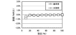
- FIG. 4 shows the flow rate error% R.
- D ( ⁇ mark) and flow rate error% R of the flow rate controller obtained by using a flow rate controller to be calibrated (hereinafter referred to as a T1000 flow rate controller) adjusted by a calibrated flow rate controller, which will be described later, as a reference flow meter .
- D ( ⁇ mark) is contrasted.
- the flow rate calibration by the build-up method according to the present invention uses the T1000 flow controller as the reference flow meter.
- Flow rate error% R It can be seen that D is small.
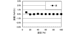
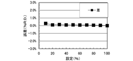
- Table 2 shows the flow rate error% R.
- D the flow rate error% R.
- the calibrated flow rate controller is calibrated as a reference flow meter. The difference from D is shown.
- FIG. 5 is a graph showing the difference in error shown in Table 2 above, and it can be seen that the calibration method of the present invention enables highly accurate flow rate calibration even in a small region where the set flow rate is 100 sccm or less.
- Table 3 shows the test results of the second embodiment of the present invention.
- a chamber (internal volume of 170.36 cc) having an inner diameter of 20 mm ⁇ is used as the build-up tank BT, and the temperature detector Td is 0.25 ⁇ m. thermocouple, is measured and calculated value when the capacitance of 100Torr pressure detector Pd, the inlet-side valve V 1 and the outlet-side on-off valve V 2 Cv value was fast off valve 0.1.
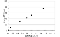
- FIG. 6 shows the result of the investigation
- FIG. 7 is an enlarged view of part A of FIG. 6 and 7, when the internal volume of the build-up tank BT is about 120.36 cc, the gas supply flow rate is 1.6 SLM and the internal pressure is increased to about 100 Torr (the on-off valve V 1 , V 2 is off valve Cv value 0.1).
- T1000 is a calibrated flow rate controller adjusted by the calibrated flow rate control device or the like.
- the flow rate controller to be calibrated includes a thermal type flow rate controller and a pressure type flow rate controller.
- the pressure value on the output side (secondary side) is 100 Torr or less. It is necessary to. Therefore, when the build-up tank volume is 100 to 150 cc, the calibration flow rate must be 1000 sccm or less.
- the set flow rate of the flow rate controller to be measured is also used in the test of Table 3 above. Is set to 100 sccm to 10 sccm.
- FIG. 8 shows the flow rate error% R. Calibrated by the build-up method of the present invention shown in Table 3 above. D, and a flow rate error% R.C. Calibrated using a calibrated flow rate controller as a standard flow meter. D is a contrast between the two and the flow rate error% R. It was found to be in the range of D.
- Table 4 shows the flow rate error% R.
- Table 5 shows the set flow rate of the flow rate controller to be calibrated (around 10 sccm and 100 sccm), the build-up time ⁇ t, the calculated flow rate, and the flow rate error% R.
- D indicates a relationship with D. As the build-up time ⁇ t is longer, the error% R. It turns out that D becomes small.
- FIG. 10 is a diagram obtained by plotting the data in Table 8, where ⁇ represents the flow rate error% R. D and ⁇ indicate the gas pressure Torr in the tank, and ⁇ indicates the gas temperature in the tank ° C.
- Table 7 shows the relationship between the volume of the build-up tank BT and the actual time from the gas base pressure Po until the tank internal pressure reaches 100 Torr.
- the set flow rate is 10 to 100 sccm and the internal volume is about 10 to 200 cc. It can be seen that the range is applicable in terms of build-up time.
- Table 8 shows an actual measurement of the relationship between the internal volume cc of the build-up tank BT, the gas set flow rate, the gas base pressure Po, and the gas pressure increase rate (Torr / sec) in the tank BT.
- the internal volume of the build-up tank BT is 50 in view of the actual set flow rate of the flow rate controller to be calibrated, the build-up time ⁇ t, the setting location, and the like. It was found that about 200cc was optimal.
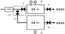
- FIG. 11 is a system diagram of a flow rate controller calibration unit used in the third embodiment of the present invention, where T1000 is a flow rate controller to be calibrated adjusted by a calibrated flow rate control device, ST is a waste chamber, V 1 is an inlet side opening / closing valve of the build-up tank BT, V 1S is an inlet side opening / closing valve of the disposal chamber, and V 2S is an outlet side opening / closing valve of the disposal chamber.
- the inlet side opening / closing valves V 1 and V 1S may be used in place of the double three-way valve V 3 .
- the flow rate controller calibration unit is discarded as shown in FIG. 11 and provided with the chamber ST, and flow rate calibration and flow rate measurement are performed by the following operations.
- the outlet side switching valve V 2S outlet side valve V 2 and discarded chamber ST buildup chamber BT opened, both chambers BT, evacuated through the ST.
- the inlet side on-off valve V 1 and the inlet side on-off valve V 1S on the upstream side are of course closed.
- the internal volume of the build-up chamber BT is selected to be 10 L
- the internal volume of the discard chamber ST is selected to be 80 L.
- both the outlet side opening / closing valves V 2 and V 2S are closed, the inlet side opening / closing valve V 1 of the buildup chamber BT is closed, the inlet side opening / closing valve V 1S of the discard chamber ST is opened, and the flow rate controller T1000 The gas is discarded through and supplied into the chamber ST.
- the embodiments The first measurement as described in is started. Further, during the required first measurement, the outlet side opening / closing valve V2S of the waste chamber ST is opened, and the gas in the waste chamber ST is gradually exhausted.
- the inlet side on-off valve V 1 of the build-up chamber BT is closed and held so that the temperature becomes stable, and then the second necessary measurement as described in the above embodiment is performed. Further, during this time, the gas in the discard chamber ST is gradually exhausted. Thereafter, while gradually evacuating the interior of the gas to the outlet side switching valve V 2 buildup chamber BT to open, if lowered until the gas pressure in the abandoned chamber ST to some extent, then to the once exhausted, Return to the initial state before the measurement.
- the present invention can be used for calibration tests not only for gas boxes for semiconductor manufacturing apparatuses but also for flow controllers for all gas supply devices and flow controllers for gas supply systems.
- GF gas supply devices MFC 1 to MFC n flow controllers Go to Gn supply gas types L, L 1 to L n gas supply paths Voo to Von open / close valve CH process chamber VP vacuum pump Td temperature detector Pd pressure detector BT build-up Tank (build-up chamber) DESCRIPTION OF SYMBOLS 1 Pressure regulator 2 Pressure gauge 3, 4 On-off valve 5 Flow controller calibration unit CP Calculation control part T1000 Calibrated flow controller ST adjusted by the calibrated flow controller etc.
- Throwing chamber V 3 Duplex three-way valve V 1S Disposal chamber inlet side open / close valve V 2S discard chamber outlet side open / close valve
Abstract
Description
また、上記各流量制御器の流量校正やその流量計測は、一般にビルドアップ法(若しくは圧力上昇率(ROR)法)により適宜の時間間隔で行われており、流量制御器の設定流量とビルドアップ法等により計測した現実の制御流量とを対比して流量制御器の流量校正を行ったり、ビルドアップ法等による計測値から流量を求める流量計測が行われている。
図1において、GFはガス供給装置、MFC1~MFCnは流量制御器、Go~Gnは供給ガス、L~Ln、Lsはガス供給路、V00~V0nは開閉弁、V0は開閉弁、V1及びV2は開閉弁、CHはプロセスチャンバ、VPは真空ポンプ、Tdは温度検出器、Pdは圧力検出器、BTはビルドアップタンク、1は圧力調整器、2は圧力計、3・4は弁、5は流量制御器校正ユニット、CPは演算制御部であり、ガス供給装置GFからガス供給流路L、弁V0を通してプロセスチャンバCHへ所定のガスが切替え供給されている。
また、流量制御器校正ユニット5の圧力検出器Pd及び温度検出器Tdの各検出出力、開閉弁V1及び開閉弁V2の制御信号等は演算制御部CPへ入出力されており、後述するようにガス流量値の演算や流量校正、流量制御精度の演算及び表示等が行われる。
尚、流量制御器にはフジキン製の容量100sccm及び1SLMのものを使用しており、ビルドアップBTの内容積Vは1.0996L(既知)に設定されている。また、ガス流量(N2)は500sccm、ビルドアップ時間は10secに設定している。更に外気温度(室内温度)は21.7℃であった。
尚、圧力検出器PdにはMKS製の(バラトロン)キャパシタンスマノメーターTYPE627D(F.S.1000Torr)を、また温度検出器Tdには2.5mm径の熱電対(素線タイプ)を、測定機器にはキーエンス製のデータロガーNR500を使用している。
タンクBT内へのガスのビルドアップが進行し、ガス圧力が設定値P1(又は設定時間t1)に達すると、入口側開閉弁V1を急閉する。
尚、時刻t2における第2回目の圧力及び温度の検出が終れば、これと同時又は時刻t3において出口側開閉弁V2を開放して、タンクBT内のガスを排出する。


図6は、その調査結果を示すものであり、また、図7は図6のA部の拡大図である。
図6及び図7からも明らかなように、ビルドアップタンクBTの内容積が120.36cc程度の場合には、ガス供給流量が1.6SLMで内圧が100Torr程度に上昇する(開閉弁V1、V2はCv値0.1の開閉弁)。尚、T1000は前記校正済みの流量制御機器等によって調整された被校正流量制御器である。


そのため、流量制御器校正ユニットを図11のように捨てチャンバSTを備えたユニットとして、下記の如き操作により流量校正や流量計測を行う。
その後、ビルドアップチャンバBTの出口側開閉弁V2を開にして内部のガスを徐々に排気すると共に、捨てチャンバST内のガス圧がある程度にまで下降すれば、その後は一気に排気をして、前記測定前の初期状態に戻る。
MFC1~MFCn 流量制御器
Go~Gn 供給ガス種
L,L1~Ln ガス供給路
Voo~Von 開閉弁
CH プロセスチャンバ
VP 真空ポンプ
Td 温度検出器
Pd 圧力検出器
BT ビルドアップタンク(ビルドアップチャンバ)
1 圧力調整器
2 圧力計
3,4 開閉弁
5 流量制御器校正ユニット
CP 演算制御部
T1000 校正済みの流量制御機器等によって調整された被校正流量制御器
ST 捨てチャンバ
V3 二連三方バルブ
V1S 捨てチャンバの入口側開閉弁
V2S 捨てチャンバの出口側開閉弁
Claims (3)
- 複数の種類のガスを各流量制御器を通して切換え可能にガス使用箇所へ供給するガス供給装置に於いて、前記ガス供給装置のガス供給路Lに、内容積VのビルドアップタンクBTとタンクBTの入口側開閉弁V1及び出口側開閉弁V2とタンクBT内ガスのガス圧力検出器Pd及びガス温度検出器Tdとから成る流量制御器校正ユニット5を分岐状に連結すると共に、当該流量制御器校正ユニット5の出口側開閉弁V2を真空排気装置に接続し、先ず、前記流量制御装置の各流量制御器の出口側開閉弁Vo1~Von及びガス使用箇所の入口開閉弁V0を閉鎖すると共に前記校正ユニット5の出口側開閉弁V2及び入口側開閉弁V1を開放し、次に、被校正流量制御器の出口側開閉弁のみを開放して設定流量のガスを前記校正ユニット5へ流入させ、前記タンク内のガス圧力及びガス温度が安定した時刻に第1回のタンク内のガス温度T0及びガス圧力P0を計測し、そして、時刻t0に於いて前記校正ユニット5の出口側開閉弁V2を閉鎖してタンクBT内へのガスのビルドアップを行い、その後、時刻t1に於いて入口側開閉弁V1を閉鎖すると共に、前記入口側開閉弁V1の閉鎖後の時刻t2に於いて第2回のガス温度T2及びガス圧力P2を計測し、前記各計測値からガス流量QをQ=(22.4V/R・Δt)×(P2/T2-P0/T0)(但し、VはタンクBTの内容積、Rはガス定数、Δtはビルドアップ時間t1-t0である)として演算し、前記設定ガス流量と演算ガス流量Qとの対比により被校正流量制御器の流量校正を行うことを特徴とするガス供給装置用流量制御器の校正方法。
- ガス供給装置を半導体製造装置用のガスボックスとすると共に、校正ユニット5をガス供給装置のガスボックス内に設けるようにした請求項1に記載のガス供給装置用流量制御器の校正方法。
- 流体供給源から流れる流体を制御する流量制御器の流量を計測する方法において、前記流量制御器の下流にある内容積VのビルドアップタンクBTと、タンクBTの入口側及び出口側に配置される入口側開閉弁V1及び出口側開閉弁V2と、タンクBT内に配置されるガス圧力検出器Pd及び温度検出器Tdとからなり、前記流量制御器から流体を流した状態で入口側開閉弁V1及び出口側開閉弁V2を開放してガスをタンクBT内に流入させるステップ、ガス圧力及びガス温度が安定した時のガス圧力P0及びガス温度T0を測定するステップ、時刻t0に於いて出口側開閉弁V2のみを閉鎖してタンクBT内へガスを充填するステップ、時刻t1に入口側開閉弁V1を閉鎖するステップ、その後時刻t2まで前記入口側開閉弁V1及び出口側開閉弁V2の閉鎖を保持するステップ、前記入口側開閉弁V1及び出口側開閉弁V2の閉鎖中に再びガス温度T2及びガス圧力P2を計測するステップ、各計測結果からガス流量QをQ=(22.4V/R・Δt)×(P2/T2-P0/T0)(但し、VはタンクBTの内容積、Rはガス定数、Δtはビルドアップ時間t1-t0である)として演算するステップ、とを備える流量計測方法。
Priority Applications (3)
| Application Number | Priority Date | Filing Date | Title |
|---|---|---|---|
| CN201180037208.5A CN103003766B (zh) | 2010-07-30 | 2011-06-28 | 气体供给装置用流量控制器的校正方法及流量计测方法 |
| US13/813,219 US9638560B2 (en) | 2010-07-30 | 2011-06-28 | Calibration method and flow rate measurement method for flow rate controller for gas supply device |
| KR1020127030272A KR101492460B1 (ko) | 2010-07-30 | 2011-06-28 | 가스 공급 장치용 유량 제어기의 교정 방법 및 유량 계측 방법 |
Applications Claiming Priority (2)
| Application Number | Priority Date | Filing Date | Title |
|---|---|---|---|
| JP2010-171626 | 2010-07-30 | ||
| JP2010171626A JP5538119B2 (ja) | 2010-07-30 | 2010-07-30 | ガス供給装置用流量制御器の校正方法及び流量計測方法 |
Publications (1)
| Publication Number | Publication Date |
|---|---|
| WO2012014375A1 true WO2012014375A1 (ja) | 2012-02-02 |
Family
ID=45529614
Family Applications (1)
| Application Number | Title | Priority Date | Filing Date |
|---|---|---|---|
| PCT/JP2011/003679 WO2012014375A1 (ja) | 2010-07-30 | 2011-06-28 | ガス供給装置用流量制御器の校正方法及び流量計測方法 |
Country Status (6)
| Country | Link |
|---|---|
| US (1) | US9638560B2 (ja) |
| JP (1) | JP5538119B2 (ja) |
| KR (1) | KR101492460B1 (ja) |
| CN (1) | CN103003766B (ja) |
| TW (1) | TWI444800B (ja) |
| WO (1) | WO2012014375A1 (ja) |
Cited By (3)
| Publication number | Priority date | Publication date | Assignee | Title |
|---|---|---|---|---|
| US10113893B2 (en) | 2013-09-13 | 2018-10-30 | Air Products And Chemicals, Inc. | Method of, and apparatus for, monitoring the available resources of a gas cylinder |
| JP2021025789A (ja) * | 2019-07-31 | 2021-02-22 | 株式会社フジキン | 流量測定システムおよび流量測定方法 |
| CN112945326A (zh) * | 2021-02-23 | 2021-06-11 | 吉林大学 | 气体流量测量装置及方法 |
Families Citing this family (46)
| Publication number | Priority date | Publication date | Assignee | Title |
|---|---|---|---|---|
| US9334069B1 (en) * | 2012-10-23 | 2016-05-10 | The Boeing Company | Propellant gauging at microgravity within the pressure—temperature—density inflection zone of xenon |
| US10810634B2 (en) * | 2013-02-08 | 2020-10-20 | The Nielsen Company (Us), Llc | Methods and apparatus for efficient execution of modules |
| JP5797246B2 (ja) * | 2013-10-28 | 2015-10-21 | 株式会社フジキン | 流量計及びそれを備えた流量制御装置 |
| CN103730392A (zh) * | 2013-11-15 | 2014-04-16 | 中微半导体设备(上海)有限公司 | 一种半导体处理装置的供气系统 |
| CN104733347B (zh) * | 2013-12-24 | 2018-03-09 | 北京北方华创微电子装备有限公司 | 半导体加工设备中气体切换的装置、方法及系统 |
| CN103900665B (zh) * | 2014-03-25 | 2016-08-31 | 重庆市计量质量检测研究院 | 容器组合及换向阀式pVTt法气体流量装置 |
| CN103954711A (zh) * | 2014-04-01 | 2014-07-30 | 聚光科技(杭州)股份有限公司 | 一种质谱检测器标定装置及方法 |
| JP6541584B2 (ja) * | 2015-09-16 | 2019-07-10 | 東京エレクトロン株式会社 | ガス供給系を検査する方法 |
| JP6554404B2 (ja) | 2015-11-25 | 2019-07-31 | 東京エレクトロン株式会社 | ガス温度測定方法及びガス導入システム |
| CN108496064B (zh) * | 2016-01-15 | 2020-05-22 | 株式会社富士金 | 能够测定流量的气体供给装置、流量计以及流量测定方法 |
| JP6647905B2 (ja) * | 2016-02-17 | 2020-02-14 | 株式会社日立ハイテクノロジーズ | 真空処理装置 |
| US10453721B2 (en) * | 2016-03-15 | 2019-10-22 | Applied Materials, Inc. | Methods and assemblies for gas flow ratio control |
| CN105841781B (zh) * | 2016-03-16 | 2018-09-28 | 中国大唐集团科学技术研究院有限公司华东分公司 | 一种标定汽轮机供热蒸汽流量的方法 |
| CN105865586B (zh) * | 2016-04-26 | 2018-12-28 | 中国大唐集团科学技术研究院有限公司华东分公司 | 一种汽轮机中排供热蒸汽流量在线标定方法 |
| JP6795832B2 (ja) * | 2016-07-05 | 2020-12-02 | 株式会社フジキン | 流量制御機器、流量制御機器の流量校正方法、流量測定機器および流量測定機器を用いた流量測定方法 |
| JP6754648B2 (ja) * | 2016-09-15 | 2020-09-16 | 東京エレクトロン株式会社 | ガス供給系の検査方法、流量制御器の校正方法、及び、二次基準器の校正方法 |
| JP6767232B2 (ja) * | 2016-10-14 | 2020-10-14 | 東京エレクトロン株式会社 | 基板処理装置の流量制御器によって出力されるガスの出力流量を求める方法 |
| JP6775403B2 (ja) * | 2016-12-14 | 2020-10-28 | 株式会社堀場エステック | 流体特性測定システム |
| CN110234965B (zh) | 2017-02-10 | 2020-10-27 | 株式会社富士金 | 流量测定方法以及流量测定装置 |
| JP6670791B2 (ja) * | 2017-03-30 | 2020-03-25 | 東京エレクトロン株式会社 | 流量制御器を検査する方法及び被処理体を処理する方法 |
| JP7105765B2 (ja) * | 2017-05-11 | 2022-07-25 | 株式会社堀場エステック | 液体材料気化供給装置及び制御プログラム |
| KR102250969B1 (ko) * | 2017-07-31 | 2021-05-12 | 가부시키가이샤 후지킨 | 유체 제어 시스템 및 유량 측정 방법 |
| CN107421608A (zh) * | 2017-08-18 | 2017-12-01 | 北京首钢自动化信息技术有限公司 | 一种气体流量计的系统校准方法 |
| CN107355681B (zh) * | 2017-08-23 | 2019-09-10 | 兰州空间技术物理研究所 | 一种用于多工质气体微流量校准的供气装置及供气方法 |
| JP6960278B2 (ja) | 2017-08-31 | 2021-11-05 | 東京エレクトロン株式会社 | 流量測定システムを検査する方法 |
| JP6851953B2 (ja) * | 2017-10-30 | 2021-03-31 | アークレイ株式会社 | ポンプ駆動方法 |
| CN108121370B (zh) * | 2017-12-23 | 2020-06-02 | 东北大学 | 一种真空环境气体流量的测控方法及测控系统 |
| JP6956014B2 (ja) | 2018-01-09 | 2021-10-27 | 東京エレクトロン株式会社 | ガスの流量を求める方法 |
| CN108286625A (zh) * | 2018-01-22 | 2018-07-17 | 博纳斯威阀门股份有限公司 | 一种排气阀的检测装置 |
| CN111788534A (zh) * | 2018-02-26 | 2020-10-16 | 株式会社富士金 | 流量控制装置以及流量控制方法 |
| JP7042134B2 (ja) | 2018-03-29 | 2022-03-25 | 東京エレクトロン株式会社 | 基板処理システム及びガスの流量を求める方法 |
| KR102443580B1 (ko) | 2018-04-28 | 2022-09-16 | 어플라이드 머티어리얼스, 인코포레이티드 | 가스 펄싱 기반 공유 전구체 분배 시스템 및 사용 방법들 |
| JP7061932B2 (ja) | 2018-06-08 | 2022-05-02 | 東京エレクトロン株式会社 | 流量測定方法および流量測定装置 |
| JP7296699B2 (ja) * | 2018-07-02 | 2023-06-23 | 東京エレクトロン株式会社 | ガス供給システム、プラズマ処理装置およびガス供給システムの制御方法 |
| KR102545945B1 (ko) | 2018-07-30 | 2023-06-21 | 가부시키가이샤 후지킨 | 유량 제어 시스템 및 유량 측정 방법 |
| US10760944B2 (en) | 2018-08-07 | 2020-09-01 | Lam Research Corporation | Hybrid flow metrology for improved chamber matching |
| CN109297703A (zh) * | 2018-11-30 | 2019-02-01 | 博纳斯威阀门股份有限公司 | 一种多级调压的检测装置 |
| JP2020139864A (ja) * | 2019-02-28 | 2020-09-03 | 株式会社堀場エステック | 流量算出システム、流量算出システム用プログラム、流量算出方法、及び、流量算出装置 |
| JP7273596B2 (ja) * | 2019-04-08 | 2023-05-15 | 株式会社堀場エステック | 流量算出装置、流量算出システム、及び、流量算出装置用プログラム |
| JP7413073B2 (ja) | 2020-02-21 | 2024-01-15 | 東京エレクトロン株式会社 | 流量測定方法および流量測定装置 |
| JP7432400B2 (ja) | 2020-03-11 | 2024-02-16 | 東京エレクトロン株式会社 | 基板処理方法及び基板処理システム |
| JP7306300B2 (ja) * | 2020-03-13 | 2023-07-11 | 株式会社島津製作所 | 推定器および真空バルブ |
| JP2022076382A (ja) * | 2020-11-09 | 2022-05-19 | 東京エレクトロン株式会社 | 処理装置及び処理方法 |
| CN112903058A (zh) * | 2021-01-25 | 2021-06-04 | 北京中建建筑科学研究院有限公司 | 一种容积检测装置及检测方法 |
| CN113959533B (zh) * | 2021-09-16 | 2023-08-11 | 张家港氢芯电气系统科技有限公司 | 一种高精度高压氢气质量流量计标定方法 |
| CN116149385B (zh) * | 2022-12-03 | 2024-04-09 | 中国科学院力学研究所 | 一种高精度微流量气体控制装置和标定方法 |
Citations (6)
| Publication number | Priority date | Publication date | Assignee | Title |
|---|---|---|---|---|
| JPH08247827A (ja) * | 1995-03-09 | 1996-09-27 | Agency Of Ind Science & Technol | 臨界ノズルの簡易校正装置及びその方法 |
| JP2003065814A (ja) * | 2001-08-28 | 2003-03-05 | Rikogaku Shinkokai | 気体用機器の流量特性計測装置および流量特性計測方法 |
| WO2005123236A1 (ja) * | 2004-06-22 | 2005-12-29 | Tokyo Electron Limited | 基板処理装置 |
| WO2006075406A1 (ja) * | 2005-01-17 | 2006-07-20 | Tokyo Meter Co., Ltd. | 流量測定方法および流量測定装置 |
| JP2007214406A (ja) * | 2006-02-10 | 2007-08-23 | Hitachi Metals Ltd | 流量検定機能付質量流量制御装置を搭載した半導体製造装置 |
| JP2009145986A (ja) * | 2007-12-11 | 2009-07-02 | Fujikin Inc | 圧力制御式流量基準器及びこれに用いる耐食性圧力式流量制御器 |
Family Cites Families (10)
| Publication number | Priority date | Publication date | Assignee | Title |
|---|---|---|---|---|
| CN1574200A (zh) * | 2003-05-12 | 2005-02-02 | 艾格瑞系统有限公司 | 质量流控制流量检定和校准的方法 |
| US7137400B2 (en) * | 2003-09-30 | 2006-11-21 | Agere Systems Inc. | Bypass loop gas flow calibration |
| US7082826B2 (en) * | 2004-10-14 | 2006-08-01 | Battelle Energy Alliance, Llc | Gas flow meter and method for measuring gas flow rate |
| JP4648098B2 (ja) | 2005-06-06 | 2011-03-09 | シーケーディ株式会社 | 流量制御機器絶対流量検定システム |
| WO2007102319A1 (ja) * | 2006-03-07 | 2007-09-13 | Ckd Corporation | ガス流量検定ユニット |
| CN100473956C (zh) * | 2006-11-09 | 2009-04-01 | 北京北方微电子基地设备工艺研究中心有限责任公司 | 气体流量校准的方法 |
| CN100468016C (zh) * | 2006-11-10 | 2009-03-11 | 北京北方微电子基地设备工艺研究中心有限责任公司 | 气体流量控制装置校验的方法 |
| KR101840047B1 (ko) * | 2008-01-18 | 2018-03-19 | 피포탈 시스템즈 코포레이션 | 가스 유동 제어기의 인 시투 시험을 위한 방법 및 장치 |
| US7891228B2 (en) * | 2008-11-18 | 2011-02-22 | Mks Instruments, Inc. | Dual-mode mass flow verification and mass flow delivery system and method |
| US9057636B2 (en) * | 2012-09-21 | 2015-06-16 | Horiba Stec, Co. Ltd. | Self-calibrating mechanism and self-calibrating method for flow rate sensor, and diagnostic mechanism and diagnostic method for fluid sensor |
-
2010
- 2010-07-30 JP JP2010171626A patent/JP5538119B2/ja active Active
-
2011
- 2011-06-28 US US13/813,219 patent/US9638560B2/en active Active
- 2011-06-28 CN CN201180037208.5A patent/CN103003766B/zh active Active
- 2011-06-28 WO PCT/JP2011/003679 patent/WO2012014375A1/ja active Application Filing
- 2011-06-28 KR KR1020127030272A patent/KR101492460B1/ko active IP Right Grant
- 2011-07-20 TW TW100125639A patent/TWI444800B/zh active
Patent Citations (6)
| Publication number | Priority date | Publication date | Assignee | Title |
|---|---|---|---|---|
| JPH08247827A (ja) * | 1995-03-09 | 1996-09-27 | Agency Of Ind Science & Technol | 臨界ノズルの簡易校正装置及びその方法 |
| JP2003065814A (ja) * | 2001-08-28 | 2003-03-05 | Rikogaku Shinkokai | 気体用機器の流量特性計測装置および流量特性計測方法 |
| WO2005123236A1 (ja) * | 2004-06-22 | 2005-12-29 | Tokyo Electron Limited | 基板処理装置 |
| WO2006075406A1 (ja) * | 2005-01-17 | 2006-07-20 | Tokyo Meter Co., Ltd. | 流量測定方法および流量測定装置 |
| JP2007214406A (ja) * | 2006-02-10 | 2007-08-23 | Hitachi Metals Ltd | 流量検定機能付質量流量制御装置を搭載した半導体製造装置 |
| JP2009145986A (ja) * | 2007-12-11 | 2009-07-02 | Fujikin Inc | 圧力制御式流量基準器及びこれに用いる耐食性圧力式流量制御器 |
Cited By (4)
| Publication number | Priority date | Publication date | Assignee | Title |
|---|---|---|---|---|
| US10113893B2 (en) | 2013-09-13 | 2018-10-30 | Air Products And Chemicals, Inc. | Method of, and apparatus for, monitoring the available resources of a gas cylinder |
| JP2021025789A (ja) * | 2019-07-31 | 2021-02-22 | 株式会社フジキン | 流量測定システムおよび流量測定方法 |
| JP7251786B2 (ja) | 2019-07-31 | 2023-04-04 | 株式会社フジキン | 流量測定システムおよび流量測定方法 |
| CN112945326A (zh) * | 2021-02-23 | 2021-06-11 | 吉林大学 | 气体流量测量装置及方法 |
Also Published As
| Publication number | Publication date |
|---|---|
| TW201229704A (en) | 2012-07-16 |
| US20130186471A1 (en) | 2013-07-25 |
| JP5538119B2 (ja) | 2014-07-02 |
| US9638560B2 (en) | 2017-05-02 |
| CN103003766B (zh) | 2016-01-27 |
| KR20130031260A (ko) | 2013-03-28 |
| TWI444800B (zh) | 2014-07-11 |
| CN103003766A (zh) | 2013-03-27 |
| JP2012032983A (ja) | 2012-02-16 |
| KR101492460B1 (ko) | 2015-02-11 |
Similar Documents
| Publication | Publication Date | Title |
|---|---|---|
| WO2012014375A1 (ja) | ガス供給装置用流量制御器の校正方法及び流量計測方法 | |
| JP5703032B2 (ja) | ガス供給装置用流量制御器の流量測定方法 | |
| TWI705318B (zh) | 用於以隔離閥進行脈衝氣體輸送的方法及設備 | |
| US7461549B1 (en) | Mass flow verifiers capable of providing different volumes, and related methods | |
| KR101840047B1 (ko) | 가스 유동 제어기의 인 시투 시험을 위한 방법 및 장치 | |
| JP7296726B2 (ja) | 流体制御システム | |
| JP4421393B2 (ja) | 基板処理装置 | |
| JP2008170410A (ja) | 質量流量制御装置、その検定方法及び半導体製造装置 | |
| TWI642912B (zh) | 用於暫態氣流之度量衡方法 | |
| JP7149444B1 (ja) | 圧力減衰速度に基づく質量流量点検の方法、システム、及び装置 | |
| TWI837862B (zh) | 用於基於壓力衰減速率來進行質量流驗證的方法、電子裝置製造系統及非暫態電腦可讀儲存媒體 | |
| CN117810130A (zh) | 测量气体流量的方法和校准流量控制器的方法 | |
| CN114375347A (zh) | 气体供给装置和气体供给方法 |
Legal Events
| Date | Code | Title | Description |
|---|---|---|---|
| WWE | Wipo information: entry into national phase |
Ref document number: 201180037208.5 Country of ref document: CN |
|
| 121 | Ep: the epo has been informed by wipo that ep was designated in this application |
Ref document number: 11811982 Country of ref document: EP Kind code of ref document: A1 |
|
| ENP | Entry into the national phase |
Ref document number: 20127030272 Country of ref document: KR Kind code of ref document: A |
|
| NENP | Non-entry into the national phase |
Ref country code: DE |
|
| WWE | Wipo information: entry into national phase |
Ref document number: 13813219 Country of ref document: US |
|
| 122 | Ep: pct application non-entry in european phase |
Ref document number: 11811982 Country of ref document: EP Kind code of ref document: A1 |