WO2011142281A1 - 自動車の車体構造 - Google Patents
自動車の車体構造 Download PDFInfo
- Publication number
- WO2011142281A1 WO2011142281A1 PCT/JP2011/060451 JP2011060451W WO2011142281A1 WO 2011142281 A1 WO2011142281 A1 WO 2011142281A1 JP 2011060451 W JP2011060451 W JP 2011060451W WO 2011142281 A1 WO2011142281 A1 WO 2011142281A1
- Authority
- WO
- WIPO (PCT)
- Prior art keywords
- glass
- air box
- vehicle
- vertical wall
- wall surface
- Prior art date
Links
Images


Classifications
-
- B—PERFORMING OPERATIONS; TRANSPORTING
- B60—VEHICLES IN GENERAL
- B60R—VEHICLES, VEHICLE FITTINGS, OR VEHICLE PARTS, NOT OTHERWISE PROVIDED FOR
- B60R13/00—Elements for body-finishing, identifying, or decorating; Arrangements or adaptations for advertising purposes
- B60R13/08—Insulating elements, e.g. for sound insulation
- B60R13/0815—Acoustic or thermal insulation of passenger compartments
-
- B—PERFORMING OPERATIONS; TRANSPORTING
- B62—LAND VEHICLES FOR TRAVELLING OTHERWISE THAN ON RAILS
- B62D—MOTOR VEHICLES; TRAILERS
- B62D25/00—Superstructure or monocoque structure sub-units; Parts or details thereof not otherwise provided for
- B62D25/08—Front or rear portions
- B62D25/081—Cowls
Definitions
- the present invention relates to an automobile body structure that can exhibit good sound vibration performance.
- Japanese Patent Application Laid-Open No. 2009-83745 discloses a vehicle body structure in which a front edge portion of a front window shield glass is connected to an upper surface of a cowl panel member.
- the front edge of the cowl panel member is on the rear wall side of the engine room, up to a position above the air box configured by extending a vertical wall surface portion facing the vehicle interior side in the vehicle width direction. It extends toward the front.
- the front edge part of the front window shield glass is placed on the upper surface side of the front edge part of the cowl panel member, and the lower surface side is connected to the front edge part of the cowl panel member. Is supported from below.
- the portion of the air box that supports the front window shield glass has a cantilever structure, and therefore, when glass film vibration occurs, the amplitude tends to increase.
- the volume is greatly changed, and the booming noise increases, which causes discomfort to passengers in the passenger compartment.
- An object of the present invention is to provide a vehicle body structure for an automobile capable of improving the sound vibration performance by suppressing a change in the volume of the passenger compartment.
- One aspect of the present invention is a vehicle body structure in which a front edge portion of a front window shield glass is supported by an air box having a vertical wall surface facing the vehicle interior side.
- the vertical wall surface portion of the air box is displaced in the vehicle interior outer direction
- the vertical wall surface of the air box is displaced in the vehicle interior direction.
- a front edge portion is connected to the air box.
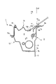
- FIG. 1 is a cross-sectional view of an automobile body structure according to an embodiment of the present invention, in which an air box and a cowl top member are cut along a plane perpendicular to the vehicle width direction.
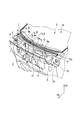
- FIG. 2 is an exploded perspective view for explaining the overall structure of the vehicle body structure of FIG. 1 and shows the vicinity of the air box with the cowl top member removed.
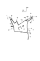
- FIG. 3 is a sectional view taken along line III-III in FIG. 4 is a cross-sectional view taken along line IV-IV in FIG.
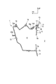
- FIG. 5 is a sectional view taken along line VV in FIG.
- FIG. 6 schematically shows a state in which the vertical wall surface portion of the air box vibrates in the opposite phase with respect to the glass film vibration in the in-plane / outside direction of the front window shield glass in the vehicle body training of FIG. It is sectional drawing.
- An air box 4 is provided in the front part of the automobile 1, between an engine room 2 provided with an engine or a motor as a drive source of the automobile 1 and a passenger compartment 3 as a passenger compartment in which an occupant is boarded.
- the air box 4 extends in the vehicle width direction and exhibits a substantially rectangular closed cross section in a longitudinal section (a section perpendicular to the vehicle width direction).
- the inner side surface of the passenger compartment 3 of the air box 4 is provided with a dash upper panel member 6.
- the dash upper panel member 6 includes, in a longitudinal section, a substantially horizontal joint portion 7a that is joined to the dash lower panel member 5, a rising portion 7b that is bent at the rear end of the joint portion 7a, and a rear end of the rising portion 7b.
- the vehicle has a vertical wall surface portion 8 that extends substantially vertically toward the vehicle upper side and faces the space inside the passenger compartment 3.
- the dash upper panel member 6 and the dash lower panel member 5 are connected so that the vertical wall surface portion 8 and the dash lower panel member 5 are substantially flush with each other at the joint portion 7a.
- the rising portion 7 b may be bent so as to extend from the rear end of the joint portion 7 a so as to incline upward and rearward of the vehicle.
- An air conditioning opening 8a is formed at a substantially central portion of the vertical wall surface portion 8 in the vehicle width direction.
- the upper edge portion of the dash upper panel member 6 is connected to the dash upper panel member 6 via a corner portion 9b that is bent from the upper end of the vertical wall surface portion 8 so as to exhibit a substantially obtuse angle L shape in the vertical cross section.
- a corner portion 9b that is bent from the upper end of the vertical wall surface portion 8 so as to exhibit a substantially obtuse angle L shape in the vertical cross section.
- an upper inclined seat portion 9 that extends obliquely upward and rearward of the vehicle is integrally formed.
- a cowl top cover bracket member 12 is fixed on the upper surface of the upper inclined seat surface portion 9.
- a seal member 11 as a support portion is attached to the upper surface 12 a of the cowl top cover bracket member 12.
- the seal member 11 extends in the vehicle width direction of the air box 4 over substantially the entire length in the vehicle width direction along the longitudinal direction thereof.
- the side surface of the air box 4 on the engine room 2 side is composed of an extension panel member 13 that extends forward from the joint portion 7a of the dash upper panel member 6 to the vehicle.
- the front edge 14a of the cowl top cover member 14 is locked to the upper surface 13a of the front edge of the extension panel member 13.
- the cowl top cover member 14 is mounted so as to substantially cover the upper opening of the air box 4 and constitutes the upper side surface of the air box 4.
- an elastic contact piece member 16 that abuts the back side near the rear edge of the engine hood (not shown) extends along the longitudinal direction in the vehicle width direction. ing.
- cowl top cover member 14 has an outside air introduction surface portion 14b formed by a plurality of vent holes 14c, which is concavely curved (so as to protrude downward).
- the rear end edge of the cowl top cover member 14 is formed in a concave shape, and a glass fitting portion 14d that fits into a front edge portion 15a of a front window shield glass (hereinafter also simply referred to as glass) 15 is provided. It is integrally formed.
- a substantially rectangular closed cross section of the air box 4 is formed by the joining portion 7a, the rising portion 7b, the vertical wall surface portion 8, the extension panel member 13, and the cowl top cover member 14 of the dash upper panel member 6. .
- the position where the front edge portion 15a of the glass 15 is fitted and supported by the glass fitting portion 14d is directly above the vertical wall surface portion 8 facing the inside of the passenger compartment 3, and is the position of the air box 4. It is provided so as to be located on the vehicle rear side from the position where the cross-sectional shape is formed. That is, the joint between the front edge portion 15a of the glass 15 and the cowl top cover member 14 is located above the vertical wall surface portion 8 and on the vehicle rear side with respect to the member constituting the substantially rectangular closed cross section of the air box 4. positioned.
- the front edge portion 15a of the glass 15 of the present embodiment is supported at a vehicle rear position with respect to the vertical wall surface portion 8. More specifically, the back surface side of the glass 15 near the front edge portion 15a is positioned below the vertical wall surface portion 8 via the seal member 11 attached to the upper surface 12a of the cowl top cover bracket member 12 and below. It is supported from.
- front edge portion 15a of the glass 15 is connected to the upper inclined seat surface portion 9 via the seal member 11 and the cowl top cover bracket member 12 at the vehicle rear position of the air box 4.
- the vertical wall surface portion 8 is configured to vibrate in the opposite phase to the glass 15 in any glass film vibration direction.
- the dash lower panel member 5 moves in the inward / outward direction dwl, dw2 of the passenger compartment 3 with the displacement of the vertical wall surface portion 8 with respect to the glass 15 in the opposite phase. It is configured to be displaced in phase.
- the rear surface side of the glass 15 near the front edge 15a is connected to the dash upper panel member 6 via the seal member 11 attached to the upper surface 12a of the cowl top cover bracket member 12, as shown in FIG. It is supported from below at a position behind the vertical wall 8.
- the front edge portion 15a of the glass 15 is connected to the upper inclined seat surface portion 9 at a position behind the air box 4 so that the glass film vibrates in the in-plane / outside direction hw of the glass 15.
- the white arrow in FIG. 6 when the glass 15 is displaced in the passenger compartment 3 inside direction hw1, the bending angle ⁇ 1 of the corner portion 9b is set to ⁇ 1 as shown by the two-dot chain line in FIG. The larger deformation of ⁇ 2 is excited, and the lower portion of the vertical wall surface portion 8 of the air box 4 and the upper portion of the dash lower panel member 5 are displaced in the passenger compartment 3 outer direction dw1 as indicated by white arrows.
- the bending angle ⁇ 2 of the corner portion 9 b occurs during the phase in which the glass 15 is displaced in the direction hw 2 outside the passenger compartment 3.
- the bending angle ⁇ 1 changes.
- the lower part of the vertical wall surface part 8 of the air box 4 and the upper part of the dash lower panel member 5 are displaced in the passenger compartment 3 inside direction dw2 as shown by the arrow in FIG.
- the dash lower panel member 5 is moved in the opposite direction from the glass 15 to the inside / outside direction dwl, dw2 of the passenger compartment 3 along with the displacement of the vertical wall surface portion 8 to the opposite phase with respect to the glass 15. Displace.
- the volume in the passenger compartment 3 (volume in the passenger compartment 3 space) indicated by the region S1 in FIG. Since the decrease (or increase) balances with the increase (or decrease) in the volume in the passenger compartment 3 indicated by the region S2 in FIG. 6, the volume change in the entire passenger chamber 3 due to glass film vibration is reduced. Can be made.
- the dash lower panel member 5 is displaced together with the vertical wall surface portion 8 in the inward / outward direction dw of the passenger compartment 3 in the opposite phase to the glass 15.
- the seal member 11 attached to the upper surface 12a of the cowl top cover bracket member 12 located on the upper inclined seating surface portion 9 on the vehicle rear side with respect to the vertical wall surface portion 8.
- the glass 15 is supported from below via.
- a glass fitting portion 14d is formed on the rear edge portion of the cowl top cover member 14 that covers the upper surface of the air box 4, and the front edge portion 15a of the glass 15 fitted to the glass fitting portion 14d is formed. As shown in FIG. 1, the position can be set to a vehicle rear position rather than the cross-sectional position of the air box 4.
- the surface area of the cowl top cover member 14 can be set large, and a large number of ventilation openings 14c can be formed in the outside air introduction surface portion 14b.
- the back side of the glass 15 in the vicinity of the front edge portion 15a is illustrated as being supported from below via the seal member 11 attached to the upper surface 12a of the cowl top cover bracket member 12.
- the support structure of the glass 15 is not limited to this, and the back side of the glass 15 in the vicinity of the front edge portion 15a is disposed on the upper inclined seating surface portion 9 without providing the seal member 11 on the cowl top cover bracket member 12.
- the structure may be supported from below via a seal member 11 directly attached thereto.
- the support structure of the glass 15 may be any structure as long as the vertical wall surface portion 8 vibrates in an opposite phase with respect to the direction of glass film vibration, and is supported by the front edge portion 15a of the glass 15.
- the shape and material of the part are not particularly limited.
- the engine is housed in the engine room 2 as a power source
- the vehicle in which the air box 4 is disposed behind the engine room 2 and in front of the passenger compartment 3 has been described as an example.
- the vehicle to which the vehicle body structure of the automobile is applied is not limited to this, and an electric vehicle in which a motor, a battery, an electronic control device or the like is provided in the engine room 2 at the front of the vehicle, or a plurality of engines and motors, etc. Any vehicle may be used as long as it has a vertical wall surface portion 8 facing the passenger compartment 3 such as a hybrid vehicle having a power source.
- the vertical wall surface portion of the air box can be vibrated in an opposite phase with respect to the glass film vibration in the in-plane and outward directions of the front window shield glass.
Abstract
フロントウインドウシールドガラス(15)の前縁部(15a)が、車室内側に面する縦壁面部(8)を有するエアボックス(4)によって支持されている自動車の車体構造である。該車体構造では、ガラス(15)の面内外方向(hw)へのガラス膜振動が、車室内側方向(hw1)へ変位する位相の際には、エアボックス(4)の縦壁面部(8)が、車室外側方向(dw1)へ変位し、ガラス(15)の面内外方向(hw)へのガラス膜振動が、車室外側方向(hw2)へ変位する位相の際には、エアボックス(4)の縦壁面部(8)が、車室内側方向(dw2)へ変位するように、ガラス(15)の前縁部(15a)が、エアボックス(4)に接続されている。
Description
本発明は、良好な音振性能を発揮できる自動車の車体構造に関するものである。
特開2009-83745号は、フロントウインドウシールドガラスの前縁部が、カウルパネル部材の上面に接続された自動車の車体構造を開示している。この車体構造では、カウルパネル部材の前縁部が、エンジンルーム後壁側で、車室内側に面する縦壁面部を車幅方向に延設して構成されるエアボックスの上方位置まで、車両前方へ向けて延設されている。そして、このカウルパネル部材の前縁部の上面側に、フロントウインドウシールドガラスの前縁部が載置されて、その下面側をカウルパネル部材の前縁部に接続することにより、フロントウインドウシールドガラスを下方から支持している。
しかしながら、上記車体構造では、エアボックスの、フロントウインドウシールドガラスを支持している部分が片持ち構造となっているため、ガラス膜振動が生じると、その振幅が増大しやすく、これにより車室内の容積が大きく変化して、こもり音が増大し、車室内の乗員に不快感を与えてしまう。そして、これを避けるためには、フロントウインドウシールドガラスを支持する部分の板厚を厚く設定する等により、支持剛性を高める必要があった。
本発明の目的は、車室内の容積の変化を抑制して、音振性能を向上させることができる自動車の車体構造を提供することにある。
本発明の一態様は、フロントウインドウシールドガラスの前縁部が、車室内側に面する縦壁面部を有するエアボックスによって支持されている自動車の車体構造である。該車体構造では、前記ガラスの面内外方向へのガラス膜振動が、前記車室内側方向へ変位する位相の際には、前記エアボックスの前記縦壁面部が、車室外側方向へ変位し、前記ガラスの面内外方向へのガラス膜振動が、前記車室外側方向へ変位する位相の際には、前記エアボックスの前記縦壁面部が、車室内側方向へ変位するように、前記ガラスの前縁部が、前記エアボックスに接続されている。
以下、図1乃至図6に基づき、本発明の実施形態にかかる自動車1の車体構造を説明する。
自動車1の前部には、図2に示すように、自動車1の駆動源としてのエンジン若しくはモータ等が設けられるエンジンルーム2と、乗員が搭乗する車室としての乗員室3との間に、エアボックス4が設けられている。エアボックス4は、車幅方向に延在し、縦断面(車幅方向に垂直な断面)において、略矩形状の閉断面を呈する。
エアボックス4の乗員室3内側側面は、ダッシュアッパパネル部材6を備えている。ダッシュアッパパネル部材6は、縦断面において、ダッシュロアパネル部材5に接合される略水平な接合部7aと、該接合部7a後端に屈曲形成された立ち上がり部7bと、該立ち上がり部7bの後端から車両上方へ向けて略鉛直に延設され、乗員室3内空間に面する縦壁面部8とを有する。ダッシュアッパパネル部材6とダッシュロアパネル部材5とは、接合部7aにおいて、縦壁面部8とダッシュロアパネル部材5とが略面一となるように接続されている。立ち上がり部7bは、図1に示すように、接合部7a後端から車両上方かつ後方へ傾斜して延在するように屈曲形成されてもよい。
縦壁面部8の車幅方向略中央部には、空調用開口8aが形成されている。
また、ダッシュアッパパネル部材6には、縦壁面部8の上端から、縦断面において略鈍角L字状を呈するように屈曲形成されたコーナ部9bを介して、ダッシュアッパパネル部材6の上縁部9aまで、車両上方かつ後方へ傾斜して延在する上部傾斜座面部9が、一体に形成されている。
上部傾斜座面部9の上面には、図1に示すように、カウルトップカバーブラケット部材12が固設されている。
カウルトップカバーブラケット部材12の上面12aには、支持部としてのシール部材11が添着されている。シール部材11は、その長手方向を車幅方向に沿わせ、エアボックス4の車幅方向長さ略全域に亘って、延在している。
また、エアボックス4のエンジンルーム2側側面は、ダッシュアッパパネル部材6の接合部7aから車両前方へ延在するエクステンションパネル部材13から構成されている。
エクステンションパネル部材13の前縁部上面13aには、カウルトップカバー部材14の前端縁14aが係止されている。カウルトップカバー部材14は、エアボックス4の上側開口を略覆うように装着されており、エアボックス4の上側側面を構成する。
カウルトップカバー部材14の前端縁14aの上面には、図示省略のエンジンフード後縁部近傍の裏面側を当接させる弾接片部材16が、車幅方向に長手方向を沿わせて延設されている。
また、カウルトップカバー部材14には、複数の通気開孔14c…によって構成される外気導入面部14bが凹状に(下方に凸となるように)湾曲形或されている。
更に、カウルトップカバー部材14の後端縁には、凹状に形成されて、フロントウインドウシールドガラス(以下、単にガラスともいう)15の前縁部15aに、嵌合するガラス嵌合部14dが、一体に形成されている。
ダッシュアッパパネル部材6の接合部7a、立ち上がり部7b、および縦壁面部8と、エクステンションパネル部材13と、カウルトップカバー部材14とから、エアボックス4の略矩形状の閉断面が形成されている。
本実施形態では、ガラス15の前縁部15aが、ガラス嵌合部14dに嵌着されて支持される位置は、乗員室3内側に面する縦壁面部8の真上で、エアボックス4の断面形状が形成される位置よりも、車両後方側に位置するように設けられている。つまり、ガラス15の前縁部15aとカウルトップカバー部材14との接合部は、縦壁面部8の上方、かつ、エアボックス4の略矩形状の閉断面を構成する部材よりも車両後方側に位置している。
また、本実施形態のガラス15の前縁部15aは、縦壁面部8よりも車両後方位置で支持されている。より具体的には、ガラス15の前縁部15a近傍の裏面側が、カウルトップカバーブラケット部材12の上面12aに添着されたシール部材11を介して、縦壁面部8よりも車両後方位置で、下方から支持されている。
更に、ガラス15の前縁部15aは、エアボックス4の車両後方位置で、シール部材11及びカウルトップカバーブラケット部材12を介して、上部傾斜座面部9に接続されている。
このため、ガラス15の面内外方向hwへのガラス膜振動が、図6中白抜き矢印で示すように、乗員室3内側方向hw1へ変位する位相の際には、エアボックス4の縦壁面部8が、図6中白抜き矢印で示すように、乗員室3外側方向dw1へ変位する。
また、ガラス15の面内外方向hwへのガラス膜振動が、図6中矢印で示すように、乗員室3外側方向hw2へ変位する位相の際には、エアボックス4の縦壁面部8が、図6中矢印に示すように、乗員室3内側方向dw2へ変位する。つまり、いずれのガラス膜振動の方向であっても、ガラス15とは逆位相に縦壁面部8が振動するように構成されている。
更に、本実施形態にかかる自動車の車体構造では、ガラス15に対する、縦壁面部8の逆位相への変位と共に、ダッシュロアパネル部材5が、乗員室3内外方向dwl,dw2へ、ガラス15とは逆位相に変位するように構成されている。
次に、本実施形態にかかる自動車の車体講造の作用効果について説明する。
本実施形態では、ガラス15の前縁部15a近傍の裏面側が、図1に示すように、カウルトップカバーブラケット部材12の上面12aに添着されたシール部材11を介して、ダッシュアッパパネル部材6の縦壁面部8よりも車両後方位置で、下方から支持されている。
このように、ガラス15の前縁部15aが、エアボックス4よりも車両後方位置で、上部傾斜座面部9に接続されていることにより、ガラス15の面内外方向hwへのガラス膜振動において、図6中白抜き矢印で示すように、ガラス15が乗員室3内側方向hw1へ変位する位相の際には、図6中二点鎖線で示すように、コーナ部9bの屈曲角度α1を、α1より大きいα2とする変形が励起されて、エアボックス4の縦壁面部8の下部及びダッシュロアパネル部材5の上部が、白抜き矢印で示すように、乗員室3外側方向dw1へ変位する。
また、ガラス15の面内外方向hwへのガラス膜振動において、図6中矢印で示すように、ガラス15が乗員室3外側方向hw2へ変位する位相の際には、コーナ部9bの屈曲角度α2が、図6中実線で示すように、屈曲角度α1へと変化する。このため、エアボックス4の縦壁面部8の下部及びダッシュロアパネル部材5の上部が、図6中矢印に示すように、乗員室3内側方向dw2へ変位する。
本実施形態にかかる自動車の車体構造では、ガラス15に対する、縦壁面部8の逆位相への変位と共に、ダッシュロアパネル部材5が、乗員室3内外方向dwl,dw2へ、ガラス15とは逆位相に変位する。
このため、本実施形態の自動車の車体構造では、ガラス15が面内外方向hwへ膜振動する際に、図6中領域S1で示す乗員室3内の容積(乗員室3内空間の体積)の減少分(または増加分)と、図6中領域S2で示す乗員室3内の容積の増加分(または減少分)とが均衡するため、ガラス膜振動による乗員室3内全体の容積変化を減少させることができる。
よって、従来のように、ガラス15の振動を抑制する為に、ガラス15を支持する部分の板厚を厚く設定する等して、支持剛性を高める必要が無く、重量増大を抑制しつつ、こもり音を減少させて音振性能を向上させることができる。
しかも、本実施形態の自動車の車体構造では、ダッシュロアパネル部材5が、縦壁面部8と共に、乗員室3内外方向dwへガラス15と逆位相に変位する。
このため、エアボックス4の縦壁面部8の乗員室3内外方向dwの変位量が小さい場合でも、ガラス15の変位による乗員室3内の容積の減少(または増加)を補償する乗員室3内の容積の増加(または減少)を確保すること(図6中では、S1と略同じ面積を有し、S1とは逆位相に変化するS2を得ること)を容易に実現し、ガラス膜振動時の乗員室3内全体の容積変化を、確実に抑制することができるようになる。
また、本実施形態にかかる自動車の車体構造では、上部傾斜座面部9上面で、縦壁面部8よりも車両後方側に位置する、カウルトップカバーブラケット部材12の上面12aに添着されたシール部材11を介して、ガラス15が、下方から支持されている。
このため、エアボックス4の上面を覆うカウルトップカバー部材14の後縁部に、ガラス嵌合部14dを形成して、このガラス嵌合部14dに嵌合されるガラス15の前縁部15aの位置を、図1に示すように、エアボックス4の断面位置よりも車両後方位置に設定することができる。
従って、カウルトップカバー部材14の表面積を大きく設定することが可能となり、多数の通気開孔14c…を外気導入面部14bに形成することができる。
よって、車外からエアボックス4内へ、多くの空調用空気を取り込むことが可能となり、空調機器の効率を向上させて燃費性能を更に良好なものとすることができる。
以上、本発明の実施形態について説明したが、この実施形態は、本発明の理解を容易にするために記載された単なる例示に過ぎず、本発明は、この実施形態に限定されるものではない。本発明の技術的範囲は、上記実施形態で開示した具体的な技術事項に限らず、そこから容易に導きうる様々な変形、変更、代替技術なども含むものである。
例えば、上記実施形態では、ガラス15の前縁部15a近傍の裏面側を、カウルトップカバーブラケット部材12の上面12aに添着されたシール部材11を介して、下方から支持したものを例示して説明してきたが、ガラス15の支持構造は、特にこれに限らず、カウルトップカバーブラケット部材12にシール部材11を設けずに、ガラス15の前縁部15a近傍の裏面側を、上部傾斜座面部9に直接添着されたシール部材11を介して下方から支持した構造でもよい。ガラス15の支持構造は、ガラス膜振動の方向に対して、逆位相に縦壁面部8が振動するように構成されているものであれば良く、ガラス15の前縁部15aに接続される支持部の形状、及び材質は、特に限定されるものではない。
また、上記実施形態では、エンジンルーム2に動力源としてエンジンを収納し、そのエンジンルーム2の後方かつ乗員室3の前方にエアボックス4を配置した車両を例示して説明してきたが、本発明の自動車の車体構造が適用される車両は、特にこれに限らず、車両前部のエンジンルーム2に、モータ、バッテリ若しくは電子制御装置等を設けた電動車両、若しくは、エンジンとモータ等との複数の動力源を有するハイブリッド車両等、乗員室3に面する縦壁面部8を有するものであれば、どのような自動車でもよい。
本出願は、2010年5月11日に出願された日本国特許願第2010-108913号に基づく優先権を主張しており、この出願の全内容が参照により本明細書に組み込まれる。
本発明によれば、フロントウインドウシールドガラスの面内外方向へのガラス膜振動に対して、エアボックスの前記縦壁面部を、逆位相に振動させることができる。これにより、車室内全体の容積変化が抑制されて、ガラスを支持する部材の板厚を厚く設定する等の支持剛性を高めることなく、こもり音を減少させることができる。
3 乗員室(車室)
4 エアボックス
8 縦壁面部
15 フロントウインドウシールドガラス(ガラス)
15a 前縁部
4 エアボックス
8 縦壁面部
15 フロントウインドウシールドガラス(ガラス)
15a 前縁部
Claims (3)
- フロントウインドウシールドガラスの前縁部が、車室内側に面する縦壁面部を有するエアボックスによって支持されている自動車の車体構造であって、
前記ガラスの面内外方向へのガラス膜振動が、前記車室内側方向へ変位する位相の際には、前記エアボックスの前記縦壁面部が、車室外側方向へ変位すると共に、前記ガラスの面内外方向へのガラス膜振動が、前記車室外側方向へ変位する位相の際には、前記エアボックスの前記縦壁面部が、車室内側方向へ変位するように、前記ガラスの前縁部が、前記エアボックスに接続されていることを特徴とする自動車の車体構造。 - 前記ガラスの前縁部は、前記エアボックスの縦壁面部よりも車両後方位置で支持されていることを特徴とする請求項1記載の自動車の車体構造。
- 前記エアボックスの縦壁面部と略面一となるように、ダッシュロアパネル部材が接続されていることを特徴とする請求項1記載の自動車の車体構造。
Priority Applications (3)
| Application Number | Priority Date | Filing Date | Title |
|---|---|---|---|
| CN201180023265.8A CN102883943B (zh) | 2010-05-11 | 2011-04-28 | 汽车的车体构造 |
| EP11780538.2A EP2570333B1 (en) | 2010-05-11 | 2011-04-28 | Vehicle body structure |
| US13/697,114 US8608235B2 (en) | 2010-05-11 | 2011-04-28 | Vehicle body structure |
Applications Claiming Priority (2)
| Application Number | Priority Date | Filing Date | Title |
|---|---|---|---|
| JP2010-108913 | 2010-05-11 | ||
| JP2010108913A JP4924739B2 (ja) | 2010-05-11 | 2010-05-11 | 自動車の車体構造 |
Publications (1)
| Publication Number | Publication Date |
|---|---|
| WO2011142281A1 true WO2011142281A1 (ja) | 2011-11-17 |
Family
ID=44914337
Family Applications (1)
| Application Number | Title | Priority Date | Filing Date |
|---|---|---|---|
| PCT/JP2011/060451 WO2011142281A1 (ja) | 2010-05-11 | 2011-04-28 | 自動車の車体構造 |
Country Status (5)
| Country | Link |
|---|---|
| US (1) | US8608235B2 (ja) |
| EP (1) | EP2570333B1 (ja) |
| JP (1) | JP4924739B2 (ja) |
| CN (1) | CN102883943B (ja) |
| WO (1) | WO2011142281A1 (ja) |
Families Citing this family (6)
| Publication number | Priority date | Publication date | Assignee | Title |
|---|---|---|---|---|
| CN103153760B (zh) * | 2010-09-28 | 2015-09-09 | 本田技研工业株式会社 | 车辆用前围上盖板定位构造 |
| WO2013005685A1 (ja) * | 2011-07-04 | 2013-01-10 | 本田技研工業株式会社 | 車両前部構造 |
| DE102012023655A1 (de) * | 2012-11-28 | 2014-05-28 | GM Global Technology Operations LLC (n. d. Gesetzen des Staates Delaware) | Kraftfahrzeug-Muldenmodul mit Dichtung |
| JP2015067015A (ja) * | 2013-09-27 | 2015-04-13 | 日本プラスト株式会社 | カウルトップカバー |
| JP2015104995A (ja) * | 2013-11-29 | 2015-06-08 | 日本プラスト株式会社 | 車両のカウル部構造 |
| CN106132814B (zh) * | 2014-04-03 | 2018-02-06 | 丰田自动车株式会社 | 车辆用前围板结构 |
Citations (6)
| Publication number | Priority date | Publication date | Assignee | Title |
|---|---|---|---|---|
| JPH0416088U (ja) * | 1990-05-30 | 1992-02-10 | ||
| JPH0546669U (ja) * | 1991-12-03 | 1993-06-22 | トヨタ車体株式会社 | 車体の前部構造 |
| JP2003191750A (ja) * | 2001-12-27 | 2003-07-09 | Toyota Motor Corp | ウインドシールドガラス支持構造 |
| JP2006206004A (ja) * | 2005-01-31 | 2006-08-10 | Toyota Motor Corp | ウインドシールドガラスの支持構造 |
| JP2007331720A (ja) * | 2006-06-19 | 2007-12-27 | Toyota Motor Corp | 車両用カウル構造 |
| JP2009083745A (ja) | 2007-10-02 | 2009-04-23 | Mazda Motor Corp | 車両のカウル部構造 |
Family Cites Families (10)
| Publication number | Priority date | Publication date | Assignee | Title |
|---|---|---|---|---|
| US4750780A (en) * | 1985-04-23 | 1988-06-14 | Mazda Motor Corporation | Dash panel configuration for a motor vehicle front body structure |
| JP2528978B2 (ja) * | 1989-11-24 | 1996-08-28 | 日産自動車株式会社 | 自動車のエアボックス構造 |
| JP2910777B2 (ja) * | 1990-05-09 | 1999-06-23 | 鐘淵化学工業株式会社 | リング状ボンデッドマグネット及びリング状樹脂スペーサー並びにそれらを用いたコンバージェンス調整装置 |
| JP3792412B2 (ja) * | 1998-10-15 | 2006-07-05 | カルソニックカンセイ株式会社 | 電気制御機器の防水機器ケース構造 |
| JP4731742B2 (ja) * | 2001-06-29 | 2011-07-27 | 富士重工業株式会社 | 車両の前部車体構造 |
| JP4329469B2 (ja) * | 2003-09-29 | 2009-09-09 | マツダ株式会社 | 車両の前部車体構造 |
| US7000979B2 (en) * | 2003-12-22 | 2006-02-21 | Nissan Technical Center North America, Inc. | Vehicle cowl structure with vent pipe |
| JP4872586B2 (ja) * | 2005-11-10 | 2012-02-08 | 日産自動車株式会社 | 車体前部構造および連結部材 |
| JP5003463B2 (ja) * | 2007-04-05 | 2012-08-15 | 日産自動車株式会社 | 車体構造 |
| JP2010064518A (ja) * | 2008-09-08 | 2010-03-25 | Nippon Plast Co Ltd | カウルトップカバーの取付構造 |
-
2010
- 2010-05-11 JP JP2010108913A patent/JP4924739B2/ja not_active Expired - Fee Related
-
2011
- 2011-04-28 US US13/697,114 patent/US8608235B2/en active Active
- 2011-04-28 WO PCT/JP2011/060451 patent/WO2011142281A1/ja active Application Filing
- 2011-04-28 CN CN201180023265.8A patent/CN102883943B/zh active Active
- 2011-04-28 EP EP11780538.2A patent/EP2570333B1/en not_active Not-in-force
Patent Citations (6)
| Publication number | Priority date | Publication date | Assignee | Title |
|---|---|---|---|---|
| JPH0416088U (ja) * | 1990-05-30 | 1992-02-10 | ||
| JPH0546669U (ja) * | 1991-12-03 | 1993-06-22 | トヨタ車体株式会社 | 車体の前部構造 |
| JP2003191750A (ja) * | 2001-12-27 | 2003-07-09 | Toyota Motor Corp | ウインドシールドガラス支持構造 |
| JP2006206004A (ja) * | 2005-01-31 | 2006-08-10 | Toyota Motor Corp | ウインドシールドガラスの支持構造 |
| JP2007331720A (ja) * | 2006-06-19 | 2007-12-27 | Toyota Motor Corp | 車両用カウル構造 |
| JP2009083745A (ja) | 2007-10-02 | 2009-04-23 | Mazda Motor Corp | 車両のカウル部構造 |
Also Published As
| Publication number | Publication date |
|---|---|
| CN102883943A (zh) | 2013-01-16 |
| JP2011235759A (ja) | 2011-11-24 |
| CN102883943B (zh) | 2015-03-18 |
| JP4924739B2 (ja) | 2012-04-25 |
| US8608235B2 (en) | 2013-12-17 |
| EP2570333B1 (en) | 2018-04-18 |
| EP2570333A4 (en) | 2014-05-14 |
| US20130057027A1 (en) | 2013-03-07 |
| EP2570333A1 (en) | 2013-03-20 |
Similar Documents
| Publication | Publication Date | Title |
|---|---|---|
| WO2011142281A1 (ja) | 自動車の車体構造 | |
| JP2012051550A (ja) | フロントウインドの支持構造 | |
| JP2008100533A (ja) | 自動車のカウルトップ構造 | |
| US9426550B2 (en) | Speaker system for a motor vehicle | |
| JP2008260331A (ja) | 自動車の前部構造 | |
| JP2017144946A (ja) | 車体構造 | |
| JP2009137416A (ja) | 自動車用ドア | |
| JP4773900B2 (ja) | 車両のドア構造 | |
| JP2008068762A (ja) | 車両の樹脂ルーフ構造 | |
| JP2006281932A (ja) | 自動車のドア構造 | |
| JPWO2011162060A1 (ja) | 車体前部構造 | |
| KR101580917B1 (ko) | 전동 압축기의 제진장치 | |
| JP2010228717A (ja) | 車両における車体前部構造 | |
| JP2006256402A (ja) | 自動車のリヤパーセル構造 | |
| JP6915600B2 (ja) | 自動車のパネル構造 | |
| JP6592799B2 (ja) | 車体前部構造 | |
| JP2018176762A (ja) | 車両の防音構造 | |
| JP2012245803A (ja) | 車両の後部車体構造 | |
| CN210122135U (zh) | 车辆下部结构 | |
| KR20110058436A (ko) | 차량용 카울 언더커버 | |
| JP2003165420A (ja) | 自動車の前部構造 | |
| JP2009012604A (ja) | 窓部構造 | |
| JP2021178558A (ja) | 車体前部構造 | |
| JP2010228718A (ja) | 車両における車体前部構造 | |
| JP2006327446A (ja) | ウインドシールド下端支持構造 |
Legal Events
| Date | Code | Title | Description |
|---|---|---|---|
| WWE | Wipo information: entry into national phase |
Ref document number: 201180023265.8 Country of ref document: CN |
|
| 121 | Ep: the epo has been informed by wipo that ep was designated in this application |
Ref document number: 11780538 Country of ref document: EP Kind code of ref document: A1 |
|
| WWE | Wipo information: entry into national phase |
Ref document number: 13697114 Country of ref document: US |
|
| NENP | Non-entry into the national phase |
Ref country code: DE |
|
| WWE | Wipo information: entry into national phase |
Ref document number: 2011780538 Country of ref document: EP |