WO2011142020A1 - Dispositif de commande de véhicule et système de commande de véhicule - Google Patents
Dispositif de commande de véhicule et système de commande de véhicule Download PDFInfo
- Publication number
- WO2011142020A1 WO2011142020A1 PCT/JP2010/058130 JP2010058130W WO2011142020A1 WO 2011142020 A1 WO2011142020 A1 WO 2011142020A1 JP 2010058130 W JP2010058130 W JP 2010058130W WO 2011142020 A1 WO2011142020 A1 WO 2011142020A1
- Authority
- WO
- WIPO (PCT)
- Prior art keywords
- vehicle
- support
- control
- free
- run
- Prior art date
Links
Images


Classifications
-
- B—PERFORMING OPERATIONS; TRANSPORTING
- B60—VEHICLES IN GENERAL
- B60K—ARRANGEMENT OR MOUNTING OF PROPULSION UNITS OR OF TRANSMISSIONS IN VEHICLES; ARRANGEMENT OR MOUNTING OF PLURAL DIVERSE PRIME-MOVERS IN VEHICLES; AUXILIARY DRIVES FOR VEHICLES; INSTRUMENTATION OR DASHBOARDS FOR VEHICLES; ARRANGEMENTS IN CONNECTION WITH COOLING, AIR INTAKE, GAS EXHAUST OR FUEL SUPPLY OF PROPULSION UNITS IN VEHICLES
- B60K6/00—Arrangement or mounting of plural diverse prime-movers for mutual or common propulsion, e.g. hybrid propulsion systems comprising electric motors and internal combustion engines ; Control systems therefor, i.e. systems controlling two or more prime movers, or controlling one of these prime movers and any of the transmission, drive or drive units Informative references: mechanical gearings with secondary electric drive F16H3/72; arrangements for handling mechanical energy structurally associated with the dynamo-electric machine H02K7/00; machines comprising structurally interrelated motor and generator parts H02K51/00; dynamo-electric machines not otherwise provided for in H02K see H02K99/00
- B60K6/20—Arrangement or mounting of plural diverse prime-movers for mutual or common propulsion, e.g. hybrid propulsion systems comprising electric motors and internal combustion engines ; Control systems therefor, i.e. systems controlling two or more prime movers, or controlling one of these prime movers and any of the transmission, drive or drive units Informative references: mechanical gearings with secondary electric drive F16H3/72; arrangements for handling mechanical energy structurally associated with the dynamo-electric machine H02K7/00; machines comprising structurally interrelated motor and generator parts H02K51/00; dynamo-electric machines not otherwise provided for in H02K see H02K99/00 the prime-movers consisting of electric motors and internal combustion engines, e.g. HEVs
- B60K6/42—Arrangement or mounting of plural diverse prime-movers for mutual or common propulsion, e.g. hybrid propulsion systems comprising electric motors and internal combustion engines ; Control systems therefor, i.e. systems controlling two or more prime movers, or controlling one of these prime movers and any of the transmission, drive or drive units Informative references: mechanical gearings with secondary electric drive F16H3/72; arrangements for handling mechanical energy structurally associated with the dynamo-electric machine H02K7/00; machines comprising structurally interrelated motor and generator parts H02K51/00; dynamo-electric machines not otherwise provided for in H02K see H02K99/00 the prime-movers consisting of electric motors and internal combustion engines, e.g. HEVs characterised by the architecture of the hybrid electric vehicle
- B60K6/48—Parallel type
- B60K6/485—Motor-assist type
-
- B—PERFORMING OPERATIONS; TRANSPORTING
- B60—VEHICLES IN GENERAL
- B60Q—ARRANGEMENT OF SIGNALLING OR LIGHTING DEVICES, THE MOUNTING OR SUPPORTING THEREOF OR CIRCUITS THEREFOR, FOR VEHICLES IN GENERAL
- B60Q1/00—Arrangement of optical signalling or lighting devices, the mounting or supporting thereof or circuits therefor
- B60Q1/02—Arrangement of optical signalling or lighting devices, the mounting or supporting thereof or circuits therefor the devices being primarily intended to illuminate the way ahead or to illuminate other areas of way or environments
- B60Q1/04—Arrangement of optical signalling or lighting devices, the mounting or supporting thereof or circuits therefor the devices being primarily intended to illuminate the way ahead or to illuminate other areas of way or environments the devices being headlights
- B60Q1/06—Arrangement of optical signalling or lighting devices, the mounting or supporting thereof or circuits therefor the devices being primarily intended to illuminate the way ahead or to illuminate other areas of way or environments the devices being headlights adjustable, e.g. remotely-controlled from inside vehicle
- B60Q1/08—Arrangement of optical signalling or lighting devices, the mounting or supporting thereof or circuits therefor the devices being primarily intended to illuminate the way ahead or to illuminate other areas of way or environments the devices being headlights adjustable, e.g. remotely-controlled from inside vehicle automatically
- B60Q1/085—Arrangement of optical signalling or lighting devices, the mounting or supporting thereof or circuits therefor the devices being primarily intended to illuminate the way ahead or to illuminate other areas of way or environments the devices being headlights adjustable, e.g. remotely-controlled from inside vehicle automatically due to special conditions, e.g. adverse weather, type of road, badly illuminated road signs or potential dangers
-
- B—PERFORMING OPERATIONS; TRANSPORTING
- B60—VEHICLES IN GENERAL
- B60W—CONJOINT CONTROL OF VEHICLE SUB-UNITS OF DIFFERENT TYPE OR DIFFERENT FUNCTION; CONTROL SYSTEMS SPECIALLY ADAPTED FOR HYBRID VEHICLES; ROAD VEHICLE DRIVE CONTROL SYSTEMS FOR PURPOSES NOT RELATED TO THE CONTROL OF A PARTICULAR SUB-UNIT
- B60W30/00—Purposes of road vehicle drive control systems not related to the control of a particular sub-unit, e.g. of systems using conjoint control of vehicle sub-units, or advanced driver assistance systems for ensuring comfort, stability and safety or drive control systems for propelling or retarding the vehicle
- B60W30/18—Propelling the vehicle
- B60W30/18009—Propelling the vehicle related to particular drive situations
- B60W30/18072—Coasting
-
- B—PERFORMING OPERATIONS; TRANSPORTING
- B60—VEHICLES IN GENERAL
- B60Q—ARRANGEMENT OF SIGNALLING OR LIGHTING DEVICES, THE MOUNTING OR SUPPORTING THEREOF OR CIRCUITS THEREFOR, FOR VEHICLES IN GENERAL
- B60Q2300/00—Indexing codes for automatically adjustable headlamps or automatically dimmable headlamps
- B60Q2300/10—Indexing codes relating to particular vehicle conditions
- B60Q2300/11—Linear movements of the vehicle
-
- B—PERFORMING OPERATIONS; TRANSPORTING
- B60—VEHICLES IN GENERAL
- B60W—CONJOINT CONTROL OF VEHICLE SUB-UNITS OF DIFFERENT TYPE OR DIFFERENT FUNCTION; CONTROL SYSTEMS SPECIALLY ADAPTED FOR HYBRID VEHICLES; ROAD VEHICLE DRIVE CONTROL SYSTEMS FOR PURPOSES NOT RELATED TO THE CONTROL OF A PARTICULAR SUB-UNIT
- B60W30/00—Purposes of road vehicle drive control systems not related to the control of a particular sub-unit, e.g. of systems using conjoint control of vehicle sub-units, or advanced driver assistance systems for ensuring comfort, stability and safety or drive control systems for propelling or retarding the vehicle
- B60W30/18—Propelling the vehicle
- B60W30/18009—Propelling the vehicle related to particular drive situations
- B60W30/18072—Coasting
- B60W2030/1809—Without torque flow between driveshaft and engine, e.g. with clutch disengaged or transmission in neutral
-
- B—PERFORMING OPERATIONS; TRANSPORTING
- B60—VEHICLES IN GENERAL
- B60W—CONJOINT CONTROL OF VEHICLE SUB-UNITS OF DIFFERENT TYPE OR DIFFERENT FUNCTION; CONTROL SYSTEMS SPECIALLY ADAPTED FOR HYBRID VEHICLES; ROAD VEHICLE DRIVE CONTROL SYSTEMS FOR PURPOSES NOT RELATED TO THE CONTROL OF A PARTICULAR SUB-UNIT
- B60W50/00—Details of control systems for road vehicle drive control not related to the control of a particular sub-unit, e.g. process diagnostic or vehicle driver interfaces
- B60W50/0097—Predicting future conditions
-
- F—MECHANICAL ENGINEERING; LIGHTING; HEATING; WEAPONS; BLASTING
- F16—ENGINEERING ELEMENTS AND UNITS; GENERAL MEASURES FOR PRODUCING AND MAINTAINING EFFECTIVE FUNCTIONING OF MACHINES OR INSTALLATIONS; THERMAL INSULATION IN GENERAL
- F16D—COUPLINGS FOR TRANSMITTING ROTATION; CLUTCHES; BRAKES
- F16D2500/00—External control of clutches by electric or electronic means
- F16D2500/10—System to be controlled
- F16D2500/106—Engine
- F16D2500/1066—Hybrid
-
- F—MECHANICAL ENGINEERING; LIGHTING; HEATING; WEAPONS; BLASTING
- F16—ENGINEERING ELEMENTS AND UNITS; GENERAL MEASURES FOR PRODUCING AND MAINTAINING EFFECTIVE FUNCTIONING OF MACHINES OR INSTALLATIONS; THERMAL INSULATION IN GENERAL
- F16D—COUPLINGS FOR TRANSMITTING ROTATION; CLUTCHES; BRAKES
- F16D2500/00—External control of clutches by electric or electronic means
- F16D2500/50—Problem to be solved by the control system
- F16D2500/508—Relating driving conditions
- F16D2500/5085—Coasting
-
- F—MECHANICAL ENGINEERING; LIGHTING; HEATING; WEAPONS; BLASTING
- F16—ENGINEERING ELEMENTS AND UNITS; GENERAL MEASURES FOR PRODUCING AND MAINTAINING EFFECTIVE FUNCTIONING OF MACHINES OR INSTALLATIONS; THERMAL INSULATION IN GENERAL
- F16D—COUPLINGS FOR TRANSMITTING ROTATION; CLUTCHES; BRAKES
- F16D2500/00—External control of clutches by electric or electronic means
- F16D2500/70—Details about the implementation of the control system
- F16D2500/704—Output parameters from the control unit; Target parameters to be controlled
- F16D2500/70422—Clutch parameters
- F16D2500/70424—Outputting a clutch engaged-disengaged signal
-
- Y—GENERAL TAGGING OF NEW TECHNOLOGICAL DEVELOPMENTS; GENERAL TAGGING OF CROSS-SECTIONAL TECHNOLOGIES SPANNING OVER SEVERAL SECTIONS OF THE IPC; TECHNICAL SUBJECTS COVERED BY FORMER USPC CROSS-REFERENCE ART COLLECTIONS [XRACs] AND DIGESTS
- Y02—TECHNOLOGIES OR APPLICATIONS FOR MITIGATION OR ADAPTATION AGAINST CLIMATE CHANGE
- Y02T—CLIMATE CHANGE MITIGATION TECHNOLOGIES RELATED TO TRANSPORTATION
- Y02T10/00—Road transport of goods or passengers
- Y02T10/60—Other road transportation technologies with climate change mitigation effect
- Y02T10/62—Hybrid vehicles
Definitions
- the present invention relates to a vehicle control device and a vehicle control system.
- Patent Document 1 discloses that a vehicle travels by automatically repeating a state in which the engine is operated to accelerate and a state in which the engine is stopped and coasted.
- a speed maintenance control device for maintaining speed is disclosed.
- the speed maintenance control device described in Patent Document 1 as described above is desired to further improve the inertia running of the vehicle, for example.
- the present invention has been made in view of the above circumstances, and an object of the present invention is to provide a vehicle control device and a vehicle control system capable of appropriately driving a vehicle in inertia.
- the vehicle control device includes a case in which the vehicle travels in a state where the power source for driving the vehicle is operated, and a state in which the operation of the power source is stopped.
- the control of the support device that supports the driving of the vehicle can be switched between inertial traveling in which the vehicle travels.
- the support device may support an operation by the driver as the driving support.
- the vehicle control device it is possible to make it easier to start the support by the support device in the inertial travel than in the normal travel.
- preparation for the support can be performed before the support is started by the support device.
- the support device may support recognition of information by a driver as the driving support.
- the inertial travel can be made easier to recognize the information by the support device than in the normal travel.
- the vehicle control device can perform the support by controlling the support device according to a vehicle on the front side in the traveling direction of the vehicle.
- the control can be switched based on the surrounding environment information of the vehicle.
- the vehicle control device can be shifted to a control for allowing the vehicle to coast by inertia according to an operation while the vehicle is traveling.
- the inertial traveling may be a traveling state in which at least one of the acceleration requesting operation for the vehicle and the deceleration requesting operation for the vehicle is not performed.
- the display device can be controlled to display the support state of the support device.
- a vehicle control system includes a power source for driving a vehicle, a support device for supporting driving of the vehicle, and a normal vehicle in which the vehicle travels with the power source activated. And a vehicle control device capable of switching the control of the support device between a case of traveling and a case of inertial traveling in which the vehicle travels with the operation of the power source stopped.
- the vehicle control system may include a display device that can display a support state of the support device.
- the vehicle control device and the vehicle control system according to the present invention switch the control of the support device between the case of normal traveling and the case of coasting, there is an effect that the vehicle can be properly coasted.
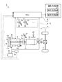
- FIG. 1 is a schematic configuration diagram of a vehicle according to the first embodiment.
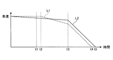
- FIG. 2 is a time chart for comparing coasting and normal traveling.
- FIG. 3 is a flowchart illustrating an example of operation support control by the ECU according to the first embodiment.
- FIG. 4 is a flowchart illustrating an example of recognition support control by the ECU according to the first embodiment.
- FIG. 5 is a schematic configuration diagram of a vehicle according to the second embodiment.
- FIG. 6 is a flowchart illustrating an example of operation support control by the ECU according to the second embodiment.
- FIG. 7 is a flowchart illustrating an example of recognition support control by the ECU according to the modification.
- FIG. 8 is a flowchart illustrating an example of recognition support control by the ECU according to the modification.
- FIG. 9 is a schematic configuration diagram of a vehicle according to the third embodiment.
- FIG. 1 is a schematic configuration diagram of a vehicle according to the first embodiment
- FIG. 2 is a time chart for comparing inertia traveling and normal traveling
- FIG. 3 illustrates an example of operation support control by the ECU according to the first embodiment
- FIG. 4 is a flowchart for explaining an example of recognition support control by the ECU according to the first embodiment.
- the vehicle control system 1 of this embodiment is a system for controlling the vehicle 2 mounted on the vehicle 2 as shown in FIG.
- the vehicle 2 consumes fuel, in this case, a power source that generates power to be applied to the drive wheels 3 of the vehicle 2 as a driving power source (prime mover) in order to drive the drive wheels 3 to rotate.
- An engine 8 is provided as an internal combustion engine that generates power to be applied to the drive wheels 3 of the vehicle 2.
- the vehicle 2 may be a so-called “hybrid vehicle” provided with a motor generator as an electric motor capable of generating electricity in addition to the engine 8 as a driving power source.
- the vehicle control system 1 includes a drive device 4, a state detection device 5, a driving support device 6 as a support device, and an ECU 7 as a vehicle control device.
- the ECU 7 stops the operation of the engine 8 in accordance with the operation of the driver and causes the vehicle 2 to coast (coast down). It is possible to shift to the control as described above, whereby the system is configured to improve the fuel consumption.
- the drive device 4 has an engine 8 as an internal combustion engine, and the drive wheel 3 is rotationally driven by the engine 8. More specifically, the drive device 4 includes an engine 8, a clutch 9, a transmission 10, a regenerative device 11, and the like. In the drive device 4, a crankshaft 12 as an output shaft of an internal combustion engine of an engine 8 and a transmission input shaft 13 of a transmission 10 are connected via a clutch 9, and a transmission output shaft 14 of the transmission 10 is a differential mechanism. And connected to the drive wheel 3 via a drive shaft or the like.
- the engine 8 is a power source that generates power that consumes fuel and acts on the drive wheels 3 of the vehicle 2, and is connected to the drive wheels 3 to generate engine torque (engine torque) that acts on the drive wheels 3. it can.
- the engine 8 is a heat engine that converts the energy of the fuel into mechanical work by burning the fuel and outputs it. Examples of the engine 8 include a gasoline engine, a diesel engine, and an LPG engine.
- the engine 8 can generate mechanical power (engine torque) on the crankshaft 12 as the fuel burns, and can output this mechanical power from the crankshaft 12 toward the drive wheels 3.
- the vehicle 2 has various starters (motors) 15, an air conditioner (not shown) compressor (so-called air conditioner compressor) 16, an alternator 17, and other various auxiliary devices for indirectly assisting the traveling of the vehicle 2. It is comprised including.
- the starter 15 is provided in the engine 8 and is driven by power supplied from the battery 18. The output of the starter 15 is transmitted to the crankshaft 12 via the power transmission unit, and thereby the crankshaft 12 of the engine 8 is rotationally started (cranking).
- the compressor 16 and the alternator 17 are provided in the engine 8, and the drive shafts 16 a and 17 a are connected to the crankshaft 12 via a power transmission unit (pulleys, belts, etc.) 19, thereby rotating the crankshaft 12. Drives in conjunction with.
- the alternator 17 can generate electric power while the engine 8 is being driven (the crankshaft 12 is rotating) and store electric power in the battery 18.
- the vehicle 2 is provided with a power storage unit (battery boost converter) 20 different from the battery 18, and can also store the generated power in the power storage unit 20.
- the clutch 9 is a mechanism that can disconnect the connection between the drive wheel 3 and the crankshaft 12 while the vehicle 2 is traveling, and is provided between the engine 8 and the drive wheel 3 in a power transmission path.
- Various known clutches can be used as the clutch 9, and the crankshaft 12 and the transmission input shaft 13 are connected so as to be able to engage in power transmission and to be disconnected so as to be unable to transmit power.
- the clutch 9 engages a crankshaft 12 that is a rotating member on the engine 8 side and a transmission input shaft 13 that is a rotating member on the drive wheel 3 side, so that the crankshaft 12 and the transmission input shaft 13 are engaged. Power can be transmitted between them, and mechanical power from the crankshaft 12 can be transmitted toward the drive wheels 3.
- the clutch 9 can cut off transmission of power between the crankshaft 12 and the transmission input shaft 13 by releasing the crankshaft 12 and the transmission input shaft 13, and is driven from the crankshaft 12.
- the mechanical power to the wheel 3 can be cut off.
- the clutch 9 can be appropriately switched between the engaged state and the released state via the intermediate half-engaged state according to the operation (clutch operation) of the clutch pedal 21 by the driver.
- the transmission 10 is provided between the clutch 9 and the drive wheel 3 in the power transmission path, and can change and output the rotational output of the engine 8.
- the transmission 10 includes, for example, a manual transmission (MT), a stepped automatic transmission (AT), a continuously variable automatic transmission (CVT), a multimode manual transmission (MMT), a sequential manual transmission (SMT), and a dual clutch transmission.
- Various known structures such as (DCT) can be used.
- the transmission 10 can change the rotational power input to the transmission input shaft 13 at a predetermined speed ratio and transmit the rotational power to the transmission output shaft 14. From the transmission output shaft 14 toward the drive wheel 3. Can be output.
- the transmission 10 will be described as a manual transmission unless otherwise specified.
- the transmission 10 as a manual transmission has a plurality of gear stages (shift stages), and an arbitrary one of the plurality of gear stages according to an operation (shift operation) of the shift lever 22 by the driver. Is selected.
- the transmission 10 transmits the power through the selected gear stage to change the rotational power input to the transmission input shaft 13 in accordance with the gear ratio assigned to the selected gear stage. And output from the transmission output shaft 14.
- the transmission 10 includes a so-called N (neutral) position.
- the transmission 10 When the N position is selected by a shift operation by the driver, the transmission 10 is in a state where there is no gear stage engagement between the transmission input shaft 13 and the transmission output shaft 14, and the transmission input shaft 13 The connection with the transmission output shaft 14 is released. Therefore, when the N position is selected, the transmission 10 is in a state in which transmission of mechanical power from the crankshaft 12 to the drive wheels 3 is interrupted even when the clutch 9 is engaged, and the engine 8 It will be in the state which does not transmit power from.
- the regenerative device 11 regenerates kinetic energy while the vehicle 2 is traveling.
- the regenerative device 11 is a device having a function as a generator that converts input mechanical power into electric power.
- the regenerative device 11 can control the presence or absence of power generation when the engine 8 is stopped.
- the regenerative device 11 is disposed on a power transmission path from the transmission output shaft 14 of the transmission 10 to the drive wheels 3.
- the regenerative device 11 can generate power by regeneration when a transmission output shaft 14 or a rotation shaft such as a propeller shaft connected to the transmission output shaft 14 is rotated by mechanical power.
- the generated electric power is stored in a power storage device such as the battery 18 or the power storage unit 20.
- the regenerative device 11 can brake (regenerative braking) this rotation by the rotational resistance generated in the transmission output shaft 14 or the rotational shaft connected to the transmission output shaft 14 so as to rotate integrally therewith.
- a braking force can be applied.
- the regenerator 11 includes, for example, a generator such as an alternator, a motor that can operate as a generator, and the like, and further has a function as an electric motor that converts supplied power into mechanical power, a so-called motor. It may be constituted by a generator.
- the vehicle 2 includes a hydraulic brake device (not shown) separately from the regenerative device 11.
- the drive device 4 configured as described above can transmit the power generated by the engine 8 to the drive wheels 3 via the clutch 9, the transmission 10, and the like.
- the driving force [N] is generated on the contact surface with the road surface of the driving wheel 3, and the vehicle 2 can travel by this.
- the drive device 4 can generate regenerative torque, which is negative torque, on the transmission output shaft 14 or the rotary shaft connected to the transmission output shaft 14 so as to rotate integrally therewith.
- the vehicle 2 can be braked by the braking force [N] generated on the contact surface with the road surface of the drive wheel 3.
- the state detection device 5 detects the state of the vehicle 2 and includes various sensors.
- the state detection device 5 is electrically connected to the ECU 7 and can exchange information such as a detection signal, a drive signal, and a control command with each other.
- the state of the vehicle 2 may include, for example, the operation state of the driver with respect to the vehicle 2, the traveling environment state of the vehicle 2, or the own vehicle state of the vehicle 2.
- the state detection device 5 includes, for example, an accelerator sensor 24 that detects an operation amount of the accelerator pedal 23 by the driver, a brake sensor 26 that detects an operation amount of the brake pedal 25 by the driver, and the like.
- the operation amount of the accelerator pedal 23 is, for example, the accelerator opening, and typically corresponds to a value corresponding to the operation amount of the acceleration request operation that the driver requests from the vehicle 2.
- the operation amount of the brake pedal 25 is, for example, the pedal depression force of the brake pedal 25, and typically corresponds to a value corresponding to the operation amount of the brake request operation requested by the driver to the vehicle 2.
- an accelerator operation described later is an acceleration request operation for the vehicle 2, and is typically an operation in which the driver steps on the accelerator pedal 23.
- the brake operation is a brake request operation for the vehicle 2 and is typically an operation in which the driver steps on the brake pedal 25.
- the state in which the accelerator operation and the brake operation are off is a state in which the accelerator opening and the pedal effort are each equal to or less than a predetermined value, typically 0 or less.
- the driving support device 6 is a device that supports driving of the vehicle 2 by the driver, and is controlled by the ECU 7.
- the driving support device 6 will be described in detail later.
- the ECU 7 controls driving of each part of the vehicle 2 such as the driving device 4.
- the ECU 7 is an electronic circuit mainly composed of a known microcomputer including a CPU, a ROM, a RAM, and an interface.
- the ECU 7 is electrically connected to various sensors provided in each part of the driving device 4 such as the engine 8.
- the ECU 7 is electrically connected to a fuel injection device of the engine 8, an ignition device, a throttle valve device, a regeneration device 11, a battery 18, an inverter (not shown), various auxiliary machines such as a starter 15 and an alternator 17, a power storage unit 20, and the like.
- the clutch 9 and the transmission 10 are connected via a hydraulic control device (not shown).
- the ECU 7 receives electric signals corresponding to detection results detected from various sensors, and outputs drive signals to these units in accordance with the input detection results to control their drive.
- the ECU 7 can start or stop the operation of the engine 8 while the vehicle 2 is traveling, and can switch between the operation state and the non-operation state of the engine 8.
- the state in which the engine 8 is operated is a state in which heat energy generated by burning fuel in the combustion chamber is output in the form of mechanical energy such as torque.
- the non-operating state of the engine 8, that is, the state in which the operation of the engine 8 is stopped is a state in which fuel is not burned in the combustion chamber and mechanical energy such as torque is not output.
- the ECU 7 stops the fuel consumption in the engine 8 of the drive device 4 in accordance with a predetermined operation of the driver while the vehicle 2 is traveling, and makes the vehicle 2 coast by inertia.
- the control can be shifted to a so-called free-run state. That is, the vehicle 2 can shift to coasting, that is, free-run according to the operation of the driver.
- the ECU 7 of the present embodiment stops the supply of fuel to the combustion chamber of the engine 8 (fuel cut), and executes power source stop control for stopping the generation of power by the engine 8. .
- the ECU 7 can perform inertial traveling that travels inertially by the inertial force of the vehicle 2 without outputting mechanical power to the engine 8 or the like of the drive device 4 and can improve fuel efficiency. That is, the free-run state of the vehicle 2 is the driving torque (driving force) generated by the engine 8 (motor torque in the case where a motor generator is provided) in the driving wheel 3 and the engine generated by the engine 8.
- the braking torque (braking force) generated by the braking torque or the braking torque generated by the braking device does not act, and the vehicle 2 travels by the inertial force of the vehicle 2 and is executed in accordance with a predetermined free-run (inertial traveling) operation by the driver. Is done.
- the ECU 7 basically prohibits regeneration by the regenerator 11 when the vehicle 2 is in a free-run state, or the minimum necessary amount. Therefore, the regenerative torque generated by the regenerative device 11 is minimized. Thereby, ECU7 can suppress that the effect of the fuel consumption improvement by using a free run during the driving
- the driver's predetermined free-run operation is performed by the driver turning off the accelerator operation while the vehicle 2 is running, For example, a series of operations may be performed in which the clutch 9 is disengaged, the N position is selected by a shift operation, and then the clutch 9 is engaged again.
- the ECU 7 stops the consumption of the fuel in the drive device 4 and shifts to a control for causing the vehicle 2 to travel inertia and to enter a free-run state. To do.
- the driver's predetermined free-run operation is, for example, that the driver turns off the accelerator operation and the brake operation while the vehicle 2 is traveling. (For example, an operation for selecting the N range by a shift operation may be added to this).
- the predetermined free-run operation of the driver is not limited to the above, and may be, for example, an operation of a switch or a lever dedicated to the free-run operation.
- the ECU 7 starts (restarts) fuel consumption in the engine 8 of the driving device 4 in accordance with a predetermined operation of the driver during a free run of the vehicle 2 and puts the vehicle 2 into a normal running state. It is possible to shift to the control.
- the normal running state of the vehicle 2 is a driving torque (driving force) generated by an engine torque (or a motor torque if a motor generator is provided) generated by the engine 8 in the driving wheel 3 or an engine brake generated by the engine 8.
- This is a running state in which braking torque (braking force) generated by torque, regenerative torque generated by the regenerative device 11 and brake torque generated by the brake device is applied, and is executed in response to a predetermined free-run releasing operation by the driver.
- the predetermined free run release operation of the driver is, for example, an operation such as a shift operation to a predetermined gear stage, an accelerator operation, or a brake operation being turned on during the free run of the vehicle 2.
- said vehicle control system 1 can recognize the information regarding driving
- this vehicle control system 1 is given, for example, auto-cruise traveling that automatically controls the vehicle speed to a predetermined vehicle speed, automatic following traveling that automatically follows a predetermined distance from the preceding vehicle, or given Compared with the case where a free run is performed as part of so-called automatic driving such as driving that generates a route plan (target trajectory) based on the conditions and creates a driving plan according to this condition and runs with automatic control. Necessary information and devices can be suppressed. Therefore, this vehicle control system 1 can improve fuel consumption with a simpler configuration, and can achieve both reduction of manufacturing cost and improvement of fuel consumption.
- the vehicle control system 1 of this embodiment is more appropriate by switching the control of the driving support device 6 between, for example, the case where the ECU 7 is a normal traveling of the vehicle 2 and the inertial traveling, that is, a free run.
- the vehicle 2 can be coasted.
- the ECU 7 of the present embodiment can execute the driving support control that supports the driving of the vehicle 2 by the driver by controlling the driving support device 6. Then, the ECU 7 performs, as the driving support control, a normal support control that is executed when the vehicle 2 is in a normal travel and a free run support control that is executed when the vehicle 2 is in a free run (inertia travel) according to the driving state. Can be switched and executed.
- the normal travel is more specifically travel using power generated by the engine 8 as travel power in an operating state in which the engine 8 is operated.
- free-running inertial running
- inertial running is running in a state where fuel consumption in the engine 8 is stopped while the operation of the engine 8 is stopped, as described above. 9, or traveling in a state where the transmission of the crankshaft 12 and the drive wheel 3 is disconnected in the transmission 10 and the rotation of the crankshaft 12 is stopped.
- the vehicle 2 typically decelerates due to running resistance received from, for example, the road surface or the atmosphere during free run.
- the free run (inertial running) of the vehicle 2 is typically a traveling state in which at least one of an acceleration requesting operation, that is, an accelerator operation, or a deceleration requesting operation, that is, a braking operation, is not performed on the vehicle 2. Then, as described above, it is a traveling state in which neither the accelerator operation nor the brake operation is performed.
- the driver recognizes the information and operates the vehicle 2 by operating the vehicle 2 according to the recognized information.
- the driving support performed by the driving support device 6 includes, for example, operation support for supporting the operation of the vehicle 2 by the driver, recognition support for supporting recognition of information by the driver, and the like.
- the driving support device 6 includes an operation support device 27 and a recognition support device 28.
- the ECU 7 can execute the operation support control for supporting the operation of the vehicle 2 by the driver by controlling the operation support device 27, and supports the recognition of information by the driver as the driving support by controlling the recognition support device 28.
- Cognitive support control can be executed.
- the operation support device 27 assists (supplies) the operation of the vehicle 2 by the driver as driving assistance.
- the operation support device 27 is typically a variety of devices that support the operation of the vehicle 2 by the driver and control the movement, behavior, posture, and the like of the vehicle 2. It is a device that controls.
- the operation support device 27 is, for example, a so-called ABS (Antilock Brake System, brake lock prevention) function, BA (Brake Assist, brake assist) function, VSC (Vehicle Stability Control, vehicle stability control) function.
- the brake actuator etc. which implement
- the brake actuator constituting the operation support device 27 is configured by, for example, a hydraulic control device (hydraulic control circuit) controlled by the ECU 7.
- the brake actuator is a plurality of pipes, oil reservoirs, oil pumps, hydraulic pipes connected to the wheel cylinders of the brake devices provided on the drive wheels 3 respectively, and the hydraulic pressures of the hydraulic pipes are increased, reduced and held respectively.
- the brake actuator is controlled by the ECU 7 so that the wheel cylinder pressure acting on each wheel cylinder is individually determined according to the operation amount (depression amount) of the brake pedal 25 by the driver or according to the state of the vehicle 2.
- the braking force acting on each drive wheel 3 can be adjusted by adjusting the pressure (increasing, depressurizing, maintaining). That is, the brake actuator can individually adjust the braking force acting on each drive wheel 3 according to the traveling state of the vehicle 2 regardless of the operation of the brake pedal 25 by the driver.
- the ECU 7 controls the brake actuator constituting the operation support device 27 to execute the operation support control.
- the operation support device 27 includes various actuators, variable stabilizers, electric power steering, active suspension, etc. that realize a so-called TRC (Traction Control System, traction control) function and VDIM (Vehicle Dynamics Integrated Management, active steering integrated control) function.
- TRC Traction Control System, traction control
- VDIM Vehicle Dynamics Integrated Management, active steering integrated control
- the recognition support device 28 supports (assists) information recognition by the driver as driving support.
- the recognition assisting device 28 typically provides various information useful for driving to the driver while driving the vehicle 2 by the driver, and reduces the information acquisition load by the driver. Thus, for example, it is a device that facilitates recognition of information by the driver and supports safety management in driving.
- the recognition support device 28 includes, for example, a headlight that assists the driver in viewing information by irradiating light at night or the like to widen the field of view of the driver.
- the headlight that constitutes the recognition support device 28 assists the front recognition in a light-insufficient state by, for example, irradiating light.
- a headlight having an auto leveling function or a light whose irradiation range can be changed can be used as the headlight constituting the recognition support device 28.
- the auto leveling function is a function of adjusting the optical axis of the headlight vertically up and down.
- the ECU 7 performs a recognition support control by controlling a headlight that forms the recognition support device 28.
- the recognition support device 28 may include various information notification devices that notify the driver of information, and the recognition support control may be performed by controlling these.
- the information notification device includes, for example, a visual information display device such as an LCD screen and an indicator attached to the navigation device, a sound output device such as a speaker that emits audio information such as sound and buzzer, a handle vibration, a seat vibration, and a pedal reaction force. Any device can be used as long as it can notify the driver of various information such as a tactile information output device that outputs tactile information.
- the information notification device may be, for example, a surrounding information notification device that notifies the surrounding information of the vehicle 2 using a so-called night vision (night vision device), radar, or the like.
- the ECU 7 switches between the normal operation support control executed when the vehicle 2 is in the normal running and the free run operation support control executed when the vehicle 2 is in the free run according to the running state. It is feasible. Similarly, the ECU 7 switches between normal recognition support control executed when the vehicle 2 is running normally and free run recognition support control executed when the vehicle 2 is running as the recognition support control according to the running state. Can be executed. In other words, the ECU 7 can execute normal operation support control and normal recognition support control as normal support control, and can execute free run operation support control and free run recognition support control as free run support control.
- the state in which the vehicle 2 is traveling in a free run is defined as a state in which driving assistance should be performed more actively than in the case of normal traveling. ing. That is, when the vehicle 2 according to the present embodiment is free-running, as described above, basically the driving torque (driving force) generated by the engine 8 on the driving wheels 3, the engine 8, the regenerative device 11, the brake device, etc. The braking torque (braking force) due to is not applied together, and the vehicle travels by inertia due to inertial force. For this reason, in the free-run state, the vehicle 2 has a tendency that the stability of the behavior is relatively lowered. Therefore, it can be said that the vehicle 2 is in a state where driving assistance is more actively performed and safety management is more actively performed. .
- the horizontal axis represents the time axis
- the vertical axis represents the vehicle speed
- the dotted line L1 represents the vehicle speed in the case of normal travel
- the solid line L2 represents the vehicle speed in the case of free run (inertia travel).
- the speed of the vehicle 2 at the time t3 tends to be higher in the free run than in the normal running.
- the vehicle 2 stops at a time t5 later than the time t4 when a braking force having the same magnitude as that in the case of normal traveling is applied after the time t3. That is, in the case of a free run, the period from the time when the driver recognizes the information on the front environment to the stop time of the vehicle 2 tends to be relatively longer than in the case of normal driving. Therefore, it can be said that the free-run state of the vehicle 2 is a state in which driving support is more actively performed and safety management is more actively performed in this respect.
- the free-run state of the vehicle 2 is a traveling state in which neither the accelerator operation nor the brake operation is performed by the driver, and the driver's intention to operate such as acceleration or braking in the first place. May be relatively low.
- the accelerator operation and the brake operation by the driver tend to be delayed with respect to the disturbance of the behavior of the vehicle 2. Therefore, it can be said that the free-run state of the vehicle 2 is a state in which driving support is more actively performed and safety management is more actively performed in this respect.
- the vehicle control system 1 recognizes information by the driver himself, performs free-run operation freely by the driver's intention according to the recognized information, and performs free-run.
- the driver recognizes and operates the information by himself and drives the vehicle 2 to perform safety management.
- this vehicle control system 1 is more prominent in the above-mentioned tendency than, for example, a case where a free run is performed as part of the above-described automatic traveling. It can be said that it is in a state that should actively support driving and more actively manage safety.
- the vehicle control system 1 tries to consciously and actively use the free run in order to improve the fuel efficiency, compared with the case where the free run is performed as part of the automatic driving described above, for example. Due to this, the above-mentioned tendency is more prominent. In this respect, it can be said that the vehicle 2 is in a state where driving assistance is more actively performed and safety management is more actively performed in the free-run state.
- the free-run state of the vehicle 2 of the present embodiment is a state in which the driver's intention to operate is not shown on the vehicle 2 side as described above, and the accelerator operation and the brake operation by the driver tend to be delayed.
- the inertial force is a state of traveling inertially and the stability of the behavior of the vehicle 2 tends to be relatively lowered, compared to the automatic traveling such as the autocruising described above, It can be said that it is in a state that should actively support driving and more actively manage safety.
- the steady running state is maintained by automatic running such as auto cruise running
- the present embodiment is basically in a state where the weak driving force is constantly acting on the driving wheels 3.
- the free-run state of the vehicle 2 is a state in which the vehicle travels inertially by inertial force, and is basically a state in which driving force and braking force other than the traveling resistance are not applied to the drive wheels 3. For this reason, the vehicle 2 tends to have relatively low vehicle stability in the free-run state, for example, in terms of wheel alignment (for example, toe angle) as compared with the steady-running state in the automatic running. This is because the wheel alignment is generally adjusted so that straightness and turning are stabilized with reference to a state in which a weak driving force is applied to the drive wheels 3.
- wheel alignment for example, toe angle
- the ECU 7 of the present embodiment switches the driving support control of the driving support device 6 so that the driving support is strengthened more in the case of the free run in the case of the normal running of the vehicle 2 and the case of the free run. .
- the ECU 7 changes the driving support control of the driving support device 6 to the safe side more positively when detecting that the vehicle 2 is in a free-run state.
- this vehicle control system 1 can respond to the above-mentioned tendency in the free-run state, and can perform free-run appropriately.
- the ECU 7 increases the support for the operation of the vehicle 2 by the driver in the case of the free run in the case of the normal running of the vehicle 2 and the case of the free run.
- the operation support control of the operation support device 27 is switched so that
- the ECU 7 makes it easier to start the operation support by the operation support device 27 in the case of a free run of the vehicle 2 than in the case of normal running.
- the ECU 7 switches the operation support control from the normal operation support control to the free run operation support control when the vehicle 2 changes from the normal run to the free run. Switch from operation support control to normal operation support control.
- the normal operation support control and the free-run operation support control typically have different operation start conditions for operation support, and the operation start condition for free-run operation support control is more than the operation start condition for normal operation support control.
- the conditions are set such that the operation support by the operation support device 27 is easily started. In other words, the ECU 7 switches between the normal operation support control and the free-run operation support control by switching the operation support start condition by the operation support device 27.
- the ECU 7 When the ECU 7 switches from the normal operation support control to the free-run operation support control, for example, the ECU 7 depresses the brake pedal 25 for determining the start of control such as ABS control, BA control, or VSC control by the operation support device 27.
- the parameter such as the amount (depressing force on the pedal), the depression speed, the yaw rate deviation, or the operation threshold set for this parameter is changed to the side where the control is easily started.
- the ECU 7 changes the operation threshold so that the operation support timing by the operation support device 27 is earlier than in the normal operation support control.
- the ECU 7 executes the normal operation support control as the operation support control. For example, it is possible to suppress wasteful consumption of energy required for control of the operation support device 27.
- the ECU 7 can execute the free-run operation support control as the operation support control, thereby suppressing a delay in the operation support by the operation support device 27. Even if the behavior or posture of the vehicle 2 is destroyed, the stability of the vehicle 2 can be reliably maintained.
- the free-run state of the vehicle 2 is a state in which driving assistance is more actively performed and safety management is more actively performed compared to the case of automatic traveling such as auto-cruising. is there.
- the ECU 7 makes it easier to start the operation support by the operation support device 27 compared to, for example, automatic driving. That is, in the free run operation support control, the ECU 7 changes the operation threshold to a side where the operation support by the operation support device 27 is more easily started than in the case of the automatic travel control.
- the ECU 7 executes free-run operation support control that makes it easier to start operation support by the operation support device 27 even in the case of free-run during automatic traveling, for example.
- the ECU 7 switches the operation support control of the operation support device 27 between the normal travel of the vehicle 2 and the free run even during automatic travel.
- the ECU 7 may prepare for the operation support before starting the operation support by the operation support device 27. That is, the ECU 7 may execute a control for preparing the operation support before starting the operation support by the operation support device 27 as the free-run operation support control.
- the ECU 7 controls a hydraulic control device (hydraulic control circuit) such as a brake actuator constituting the operation support device 27 as free-run operation support control, and executes precharge of the hydraulic pressure.
- the ECU 7 can pressurize the dead zone of the hydraulic drive of the hydraulic control device in advance by executing the precharge of the hydraulic pressure as preparation for the operation support.
- the ECU 7 executes the normal operation support control as the operation support control, so that the hydraulic pressure of the hydraulic control device is increased more than necessary during the normal travel. For example, wasteful consumption of energy required for pressurization can be suppressed.
- the ECU 7 executes the free-run operation support control as the operation support control, so that the operation support by the operation support device 27 is actually operated and the effect is obtained. Since the time until it actually appears can be shortened, the operation support by the operation support device 27 can be started with good responsiveness.
- the ECU 7 increases the support of information recognition by the driver in the case of the free run in the case of the normal running of the vehicle 2 and the case of the free run, so that it becomes more active on the safe side.
- the recognition support control of the recognition support device 28 is switched.
- the ECU 7 performs support for facilitating the recognition of information by the recognition support device 28 in the case of a free run of the vehicle 2 as compared with the case of normal running.
- the ECU 7 switches the recognition support control from the normal recognition support control to the free run recognition support control when the vehicle 2 changes from the normal run to the free run.
- the normal cognitive support control and the free run cognitive support control are different in the operation of the cognitive support device 28 in the cognitive support, and the driver of the free run cognitive support control is more aware of the information than the cognitive support of the normal cognitive support control. It is set to make it easier to recognize.
- the ECU 7 switches the light irradiation range by, for example, switching the optical axis of the headlight that forms the recognition support device 28 to the upper side in the vertical direction or increasing the amount of light. Spread relatively. Thereby, in the case of the free run of the vehicle 2, the ECU 7 can make it easier for the driver to recognize the information on the front environment, for example, than in the case of normal running.
- the vehicle control system 1 when the vehicle 2 is in the normal travel, the ECU 7 performs the normal recognition support control as the recognition support control, so that the recognition support device 28 can recognize more than necessary during the normal travel. For example, it is possible to suppress wasteful consumption of energy required for control of the recognition support device 28. And this vehicle control system 1 can make recognition of information by a driver easy by making ECU7 perform free run recognition support control as recognition support control in the case of free run of vehicles 2, and driving It is possible to make various judgments by a person at an early stage. Thus, the vehicle control system 1 can assist the driver 2 to advance the recognition time of forward environment information such as a change in the road surface by the driver (for example, time t1 in FIG. 2) when the vehicle 2 is free running. For example, it is possible to suppress delays in the accelerator operation and the brake operation by the driver, and as a result, it is possible to improve the safety management by the driver himself.
- the recognition time of forward environment information such as a change in the road surface by the driver (for example, time t1 in
- the ECU 7 acquires various types of information from the state detection device 5, and determines whether or not the current traveling state of the vehicle 2 is a free-run state by a driver's free-run operation (ST11).
- the brake is performed by the driver when there is a free-run operation and switching from normal travel to free-run. It is determined whether or not there has been an operation (ST12).
- the ECU 7 executes the free-run operation support control (free-run support control) as the operation support control, or if it has already been executed, it remains as it is.
- the ECU 7 changes the operating threshold value and executes precharge of the hydraulic pressure in order to make it easier to start the operation support by the operation support device 27 as the free-run operation support control.
- this vehicle control system 1 can strengthen the support of the operation of the vehicle 2 by the driver, and can be more actively provided on the safe side against the disturbance of the behavior of the vehicle 2 and the like.
- the ECU 7 determines that the current traveling state of the vehicle 2 is not a free-run state due to the driver's free-run operation in ST11 (ST11: No) or that the driver has performed a brake operation in ST12.
- the normal operation support control (normal support control) is executed as the operation support control, or if it is already executed, it is continued as it is (ST14), and the current control cycle is terminated. Shift to the control cycle. That is, for example, when a brake operation (deceleration request operation) is performed on the vehicle 2 immediately after shifting to a free run, the ECU 7 actively indicates the braking intention and actually performs the braking operation. Therefore, the operation support control is not switched, that is, the normal operation support control is not switched to the free-run operation support control. Thereby, this vehicle control system 1 can suppress wasteful consumption of energy.
- the ECU 7 acquires various types of information from the state detection device 5 and determines whether or not the current traveling state of the vehicle 2 is a free-run state by a driver's free-run operation (ST21).
- the ECU 7 determines whether or not the headlight that forms the recognition support device 28 is turned on. (ST22).
- the ECU 7 determines that the headlight is lit (ST22: Yes)
- the ECU 7 executes free-run recognition support control (free-run support control) as the recognition support control, or if it has already been executed, it remains as it is.
- the ECU 7 relatively widens the light irradiation range by the headlights constituting the recognition support device 28 as the free run recognition support control.
- the vehicle control system 1 can assist the driver in recognizing information such as a change in the road surface, etc., by strengthening the support for the information recognition by the driver.
- the ECU 7 determines in ST21 that the current traveling state of the vehicle 2 is not a free-run state due to the driver's free-run operation (ST21: No), or in ST22 that the headlight is not turned on. In the case (ST22: No), the normal cognitive support control (normal support control) is executed as the cognitive support control, or if it is already executed, it is continued as it is (ST24), and the current control cycle is terminated. Shift to the control cycle.
- the vehicle control system 1 and the ECU 7 can realize an improvement in fuel consumption by free running or the like at a low cost while keeping the safety of the vehicle 2 to the maximum.
- the vehicle 2 travels in a normal traveling state in which the vehicle 2 travels while the engine 8 that travels the vehicle 2 is operated, and in a state where the operation of the engine 8 is stopped.
- the control of the driving support device 6 that supports the driving of the vehicle 2 can be switched between inertial running (free run).
- the vehicle control system 1 according to the embodiment described above includes the engine 8 that causes the vehicle 2 to travel, the driving support device 6 that supports the driving of the vehicle 2, and the ECU 7. Therefore, since the vehicle control system 1 and the ECU 7 switch the control of the driving support device 6 between the normal running and the inertia running, the vehicle 2 can appropriately run the inertia.
- FIG. 5 is a schematic configuration diagram of a vehicle according to the second embodiment
- FIG. 6 is a flowchart illustrating an example of operation support control by the ECU according to the second embodiment.
- the vehicle control device and the vehicle control system according to the second embodiment are different from the first embodiment in that the control is switched based on the surrounding environment information of the vehicle.
- symbol is attached
- the state detection device 5 has a surrounding environment information acquisition device 229 as shown in FIG.
- the surrounding environment information acquisition device 229 is a device that acquires information about the surrounding environment of the vehicle 2 that is the host vehicle, and includes, for example, an in-vehicle camera, a radar, a GPS device, or a navigation device.
- the ECU7 of this embodiment switches control of the driving assistance apparatus 6 based on the surrounding environment information of the vehicle 2 which the surrounding environment information acquisition apparatus 229 acquired.
- the ECU 7 acquires the current position information and map information of the vehicle 2 from the surrounding environment information acquisition device 229, and based on these information, information such as the presence / absence of a corner on the front side in the traveling direction and the radius (curvature) of the corner And the driving support device 6 is controlled accordingly.
- the ECU 7 acquires information such as an inter-vehicle distance and a positional relationship with other vehicles (preceding vehicle, oncoming vehicle, etc.) on the front side in the traveling direction from the surrounding environment information acquisition device 229, and according to this, the driving support device 6 may be controlled.
- the ECU 7 determines whether or not to switch control based on the surrounding environment information of the vehicle 2, and switches driving support control accordingly. In this case, the ECU 7 may continue the normal support control without switching the normal support control to the free-run operation support control depending on the result of determining whether switching is required even when the vehicle 2 is free-run.
- the ECU 7 determines that the current traveling state of the vehicle 2 is a free-run state by the driver's free-run operation (ST11: Yes)
- the ECU 7 acquires and acquires the surrounding environment information of the vehicle 2 from the surrounding environment information acquisition device 229. Based on the surrounding environment information, for example, the radius of the corner on the front side in the traveling direction is smaller than the predetermined radius X set in advance, or the distance between other vehicles on the front side in the traveling direction is set in advance. It is determined whether or not it is shorter than the distance Y (ST32).
- the ECU 7 determines whether the distance between the vehicle and the other vehicle on the front side in the traveling direction is shorter than a predetermined distance Y set in advance, for example, the distance between the vehicle and the other vehicle on the front side in the traveling direction. It may be determined whether or not a time TTC obtained by converting the distance according to the vehicle speed is shorter than a predetermined time Z set in advance. Further, the predetermined radius X, the predetermined distance Y, and the predetermined time Z may be set in advance based on whether or not the environment is one in which driving assistance is more actively performed and safety management is more actively performed.
- the vehicle control system 201 and the ECU 7 operate more than necessary when the vehicle 2 is in a free-run state, but the surrounding environment of the vehicle 2 is an environment that does not require active safety management. For example, it is possible to suppress wasteful consumption of energy required for control of the operation support device 27.
- the vehicle control system 201 and the ECU 7 are more aggressive and efficient when the vehicle 2 is in a free-run state and the surrounding environment of the vehicle 2 is an environment that needs to be more actively subjected to safety management. Driving assistance can be performed.
- the ECU 7 may change the operation start condition for the operation support by the operation support device 27 based on the surrounding environment information of the vehicle 2.
- the control of the driving support device 6 is switched based on the surrounding environment information of the vehicle 2. Therefore, the vehicle control system 201 and the ECU 7 can appropriately and more effectively cause the vehicle 2 to coast by inertia according to the surrounding environment of the vehicle 2.
- the ECU 7 has been described as determining whether it is necessary to switch the operation support control by the operation support device 27 based on the surrounding environment information of the vehicle 2, but the recognition support device is based on the surrounding environment information of the vehicle 2. It may be determined whether or not it is necessary to switch the recognition support control by 28. In this case, for example, the ECU 7 may support the driving support device 6, here the recognition support device 28, according to another vehicle on the front side in the traveling direction of the vehicle 2.
- the ECU 7 first determines whether or not the current traveling state of the vehicle 2 is a night-time free-run state by a driver's free-run operation (ST41). ).
- the ECU 7 determines that the current traveling state of the vehicle 2 is a night-time free-run state by the driver's free-run operation (ST41: Yes)
- the ECU 7 obtains the surrounding environment information of the vehicle 2 from the surrounding environment information acquisition device 229. Based on the acquired and acquired surrounding environment information, the presence / absence of another vehicle on the front side in the traveling direction of the vehicle 2 and the inter-vehicle distance are acquired.
- Glare intrusion light
- the ECU 7 determines that there is no fear of being dazzled (ST42: Yes), it executes free-run recognition support control (free-run support control) (ST23), and the current running state of the vehicle 2 is the driver's free-run operation.
- free-run recognition support control free-run support control
- normal recognition support control normal support control
- ST24 normal support control
- the vehicle control system 201 and the ECU 7 can appropriately coast the vehicle 2 in consideration of, for example, other vehicles on the front side in the traveling direction of the vehicle 2 according to the surrounding environment of the vehicle 2.
- the ECU 7 has been described as executing the control for relatively widening the light irradiation range by the headlights constituting the recognition support device 28 as the free-run recognition support control, but is not limited thereto.
- the recognition support device 28 is configured to include a surrounding information notification device that notifies the surrounding information of the vehicle 2 using, for example, night vision or radar, as shown in the flowchart of FIG.
- Free-run recognition support control may be executed by controlling the surrounding information notification device forming the support device 28.
- the ECU 7 determines that the current traveling state of the vehicle 2 is a free-run state by the driver's free-run operation (ST21: Yes)
- the process of ST22 described in FIG. Run recognition support control (free run support control) can be executed (ST53).
- the ECU 7 controls the surrounding information notification device that forms the recognition support device 28 and executes free-run recognition support control
- the ECU 7 has an excessive information notification range of information to be notified to the driver via the surrounding information notification device. It should be relatively widened in a range that does not become unacceptable, or in a range suitable for the vehicle speed, deceleration, etc.
- the ECU 7 can provide assistance that facilitates recognition of information by the driver via the recognition support device 28, and support for recognition of information by the driver is strengthened, such as changes in the road surface by the driver, and the like. It is possible to assist in speeding up the recognition of information, and for example, it is possible to prompt the user to perform inertial running that matches the surrounding environment.
- FIG. 9 is a schematic configuration diagram of a vehicle according to the third embodiment.
- the vehicle control device and the vehicle control system according to the third embodiment are different from the first embodiment in that the display device is controlled and the support state of the support device is displayed.
- the vehicle control system 301 of this embodiment includes a display device 330 as shown in FIG.
- the display device 330 can display information.
- the display device 330 can display a support state of the driving support device 6.
- the ECU 7 of this embodiment controls the display device 330 to display the support state of the driving support device 6.
- the display device 330 includes, for example, an indicator and is controlled by the ECU 7.
- the ECU 7 controls the display device 330 to display a support state of the driving support device 6, for example, ON / OFF of driving support by the driving support device 6.
- the ECU 7 individually displays ON / OFF of the operation support by the operation support device 27 constituting the drive support device 6 and ON / OFF of the recognition support by the recognition support device 28 as the support state of the drive support device 6. To display.
- the display device 330 is controlled to display the support state of the driving support device 6. Therefore, the vehicle control system 301 and the ECU 7 can appropriately transmit the support state of the driving support device 6 to the driver, and, for example, prompt the driver to drive appropriately according to the support state of the driving support device 6. be able to.
- the display device 330 may be configured by, for example, an LCD screen attached to the navigation device or a so-called HUD (Head-Up Display).
- the ECU 7 controls the display device 330, and the driving support content by the driving support device 6 (the content of the operation support by the operation support device 27, the content of the recognition support by the recognition support device 28) as the support state of the driving support device 6. ) May be displayed.
- the ECU 7 has been described as switching between the operation support control of the operation support device 27 and the recognition support control of the recognition support device 28 between the normal running of the vehicle 2 and the free run. Not only this but only one of them may be switched.
- the ECU 7 makes it easier to start assistance by the driving assistance device 6 and recognizes information by the driving assistance device 6 in the case of free run (inertia running) than in the case of normal running.
- free run in the case of normal running.
- the vehicle control system 1 can shift to a control in which the ECU 7 stops the operation of the engine 8 in accordance with the driver's operation while the vehicle 2 is traveling, and the vehicle 2 is coasted to a free-run state. Although it demonstrated as there being, you may transfer to control which sets it to a free run state automatically according to the state of the vehicle 2 by control of ECU7, without a driver
- the vehicle control system 1 has been described as including the regenerative device 11, but the configuration is not limited thereto, and the regenerative device 11 may not be included.
- the power source has been described as being the engine 8, but is not limited thereto, and may be, for example, a motor generator.
- the clutch 9 or the transmission 10 is disconnected from the crankshaft 12 and the drive wheel 3 and the rotation of the crankshaft 12 is stopped.
- the present invention is not limited to this.
- the free-run state of the vehicle 2 basically, it is sufficient that the engine 8 is inactive and the vehicle 2 is in an inertial running state.
- the connection between the crankshaft 12 and the drive wheels 3 is maintained and the crankshaft 12 is maintained. May be in a state where the wheel is engaged with the drive wheel 3, that is, a state in which a braking torque by an engine brake torque acts on the drive wheel 3.
- the vehicle control device and the vehicle control system according to the present invention are suitable for application to a vehicle control device and a vehicle control system mounted on various vehicles.
Abstract
Priority Applications (5)
| Application Number | Priority Date | Filing Date | Title |
|---|---|---|---|
| JP2012514647A JP5310942B2 (ja) | 2010-05-13 | 2010-05-13 | 車両制御装置及び車両制御システム |
| CN201080066717.6A CN102892655B (zh) | 2010-05-13 | 2010-05-13 | 车辆控制装置和车辆控制系统 |
| DE112010005563.7T DE112010005563B4 (de) | 2010-05-13 | 2010-05-13 | Fahrzeugsteuerungsvorrichtung und Fahrzeugsteuerungssystem |
| US13/697,145 US8958970B2 (en) | 2010-05-13 | 2010-05-13 | Vehicle control device and vehicle control system |
| PCT/JP2010/058130 WO2011142020A1 (fr) | 2010-05-13 | 2010-05-13 | Dispositif de commande de véhicule et système de commande de véhicule |
Applications Claiming Priority (1)
| Application Number | Priority Date | Filing Date | Title |
|---|---|---|---|
| PCT/JP2010/058130 WO2011142020A1 (fr) | 2010-05-13 | 2010-05-13 | Dispositif de commande de véhicule et système de commande de véhicule |
Publications (1)
| Publication Number | Publication Date |
|---|---|
| WO2011142020A1 true WO2011142020A1 (fr) | 2011-11-17 |
Family
ID=44914088
Family Applications (1)
| Application Number | Title | Priority Date | Filing Date |
|---|---|---|---|
| PCT/JP2010/058130 WO2011142020A1 (fr) | 2010-05-13 | 2010-05-13 | Dispositif de commande de véhicule et système de commande de véhicule |
Country Status (5)
| Country | Link |
|---|---|
| US (1) | US8958970B2 (fr) |
| JP (1) | JP5310942B2 (fr) |
| CN (1) | CN102892655B (fr) |
| DE (1) | DE112010005563B4 (fr) |
| WO (1) | WO2011142020A1 (fr) |
Cited By (6)
| Publication number | Priority date | Publication date | Assignee | Title |
|---|---|---|---|---|
| JP2014083897A (ja) * | 2012-10-19 | 2014-05-12 | Toyota Motor Corp | 車両の走行制御装置 |
| JP2014083896A (ja) * | 2012-10-19 | 2014-05-12 | Toyota Motor Corp | 車両の走行制御装置 |
| EP2811194A1 (fr) * | 2012-02-03 | 2014-12-10 | Toyota Jidosha Kabushiki Kaisha | Dispositif de commande de véhicule |
| JP2016117307A (ja) * | 2014-12-18 | 2016-06-30 | トヨタ自動車株式会社 | 車両制御装置 |
| JP2017193334A (ja) * | 2017-06-19 | 2017-10-26 | トヨタ自動車株式会社 | 車両の走行制御装置 |
| JP7435192B2 (ja) | 2020-04-14 | 2024-02-21 | マツダ株式会社 | 車両制御システム |
Families Citing this family (23)
| Publication number | Priority date | Publication date | Assignee | Title |
|---|---|---|---|---|
| WO2011142020A1 (fr) | 2010-05-13 | 2011-11-17 | トヨタ自動車株式会社 | Dispositif de commande de véhicule et système de commande de véhicule |
| CN102333946B (zh) | 2010-05-19 | 2014-10-08 | 丰田自动车株式会社 | 车辆控制系统 |
| US8560202B2 (en) * | 2010-11-01 | 2013-10-15 | Ford Global Technologies, Llc | Method and apparatus for improved climate control function in a vehicle employing engine stop/start technology |
| US9447765B2 (en) | 2011-07-11 | 2016-09-20 | Ford Global Technologies, Llc | Powertrain delta current estimation method |
| US10480477B2 (en) | 2011-07-11 | 2019-11-19 | Ford Global Technologies, Llc | Electric current based engine auto stop inhibit algorithm and system implementing same |
| US9303613B2 (en) | 2012-02-24 | 2016-04-05 | Ford Global Technologies, Llc | Control of vehicle electrical loads during engine auto stop event |
| US9205717B2 (en) | 2012-11-07 | 2015-12-08 | Polaris Industries Inc. | Vehicle having suspension with continuous damping control |
| BR112015010289A2 (pt) | 2012-11-07 | 2017-07-11 | Polaris Inc | sistema de controle de amortecimento para um veículo |
| US9702349B2 (en) * | 2013-03-15 | 2017-07-11 | ClearMotion, Inc. | Active vehicle suspension system |
| US9248824B2 (en) | 2014-01-24 | 2016-02-02 | Ford Global Technologies, Llc | Rear defrost control in stop/start vehicle |
| EP3212484A2 (fr) | 2014-10-31 | 2017-09-06 | Polaris Industries Inc. | Système et procédé de commande d'un véhicule |
| AU2016265556B2 (en) | 2015-05-15 | 2019-05-02 | Polaris Industries Inc. | Utility vehicle |
| KR101646131B1 (ko) * | 2015-06-15 | 2016-08-05 | 현대자동차 주식회사 | 마일드 하이브리드 차량의 엔진 예열 장치 및 방법 |
| EP3492305B1 (fr) * | 2016-07-29 | 2021-04-14 | Nissan Motor Co., Ltd. | Procédé de commande et dispositif de commande de véhicule |
| WO2018094212A2 (fr) | 2016-11-18 | 2018-05-24 | Polaris Industries Inc. | Véhicule à suspension réglable |
| JP6532170B2 (ja) * | 2016-11-22 | 2019-06-19 | 本田技研工業株式会社 | 車両制御システム、車両制御方法、および車両制御プログラム |
| US10406884B2 (en) | 2017-06-09 | 2019-09-10 | Polaris Industries Inc. | Adjustable vehicle suspension system |
| JP2019031153A (ja) * | 2017-08-07 | 2019-02-28 | いすゞ自動車株式会社 | 走行制御装置、車両および走行制御方法 |
| DE102017222930A1 (de) | 2017-12-15 | 2019-06-19 | Zf Friedrichshafen Ag | Verfahren zum Betreiben eines Antriebsstrangs eines Kraftfahrzeugs |
| DE102017222929A1 (de) * | 2017-12-15 | 2019-06-19 | Zf Friedrichshafen Ag | Verfahren zum Betreiben eines Antriebsstrangs eines Kraftfahrzeugs |
| US10946736B2 (en) | 2018-06-05 | 2021-03-16 | Polaris Industries Inc. | All-terrain vehicle |
| US10987987B2 (en) | 2018-11-21 | 2021-04-27 | Polaris Industries Inc. | Vehicle having adjustable compression and rebound damping |
| MX2022015902A (es) | 2020-07-17 | 2023-01-24 | Polaris Inc | Suspensiones ajustables y operacion de vehiculo para vehiculos recreativos todoterreno. |
Citations (5)
| Publication number | Priority date | Publication date | Assignee | Title |
|---|---|---|---|---|
| JPH112143A (ja) * | 1997-06-11 | 1999-01-06 | Aqueous Res:Kk | 車両用制御装置 |
| JP2000255352A (ja) * | 1999-03-08 | 2000-09-19 | Mazda Motor Corp | 車両の警報装置 |
| JP2002227885A (ja) * | 2001-02-06 | 2002-08-14 | Hino Motors Ltd | クラッチ制御装置 |
| JP2006161684A (ja) * | 2004-12-07 | 2006-06-22 | Mazda Motor Corp | 車両のエンジン始動装置 |
| JP2007291919A (ja) * | 2006-04-24 | 2007-11-08 | Toyota Motor Corp | 車両用走行制御装置 |
Family Cites Families (56)
| Publication number | Priority date | Publication date | Assignee | Title |
|---|---|---|---|---|
| US3225704A (en) * | 1961-12-18 | 1965-12-28 | Alden Self Transit Syst | Transportation systems |
| US3254608A (en) * | 1965-03-29 | 1966-06-07 | Alden Self Transit Syst | Vehicles and transportation systems |
| US3532060A (en) * | 1966-12-29 | 1970-10-06 | Alden Self Transit Syst | Transportation system and vehicle |
| JPS5835245A (ja) | 1981-08-25 | 1983-03-01 | Toyota Motor Corp | エンジン自動停止始動装置 |
| USRE32474E (en) | 1982-06-07 | 1987-08-11 | Variable time delay apparatus for controlling the start of a vehicle | |
| US6048288A (en) | 1997-11-18 | 2000-04-11 | Toyota Jidosha Kabushiki Kaisha | Power train system for a vehicle and method for operating same |
| DE19911736B4 (de) | 1998-03-17 | 2005-12-15 | Honda Giken Kogyo K.K. | Maschinenstopp-Steuersystem für ein Fahrzeug |
| JP3706733B2 (ja) | 1998-03-17 | 2005-10-19 | 本田技研工業株式会社 | 車両のエンジン停止制御装置 |
| JP2000310133A (ja) | 1999-04-26 | 2000-11-07 | Toyota Motor Corp | エンジンの自動停止始動装置 |
| JP2001065675A (ja) | 1999-08-26 | 2001-03-16 | Honda Motor Co Ltd | 車両制御装置 |
| JP3675281B2 (ja) | 2000-02-15 | 2005-07-27 | 日産自動車株式会社 | 車両のエンジン自動停止再始動装置 |
| JP2001227375A (ja) | 2000-02-17 | 2001-08-24 | Mitsubishi Electric Corp | アイドルストップ装置 |
| GB2370130B (en) | 2000-10-11 | 2004-10-06 | Ford Motor Co | A control system for a hybrid electric vehicle |
| JP2002213269A (ja) | 2000-11-15 | 2002-07-31 | Toyota Motor Corp | 自動車 |
| JP2002195137A (ja) * | 2000-12-27 | 2002-07-10 | Aisin Aw Co Ltd | ハイブリッド型車両及びその制御方法 |
| JP2002216113A (ja) * | 2001-01-16 | 2002-08-02 | Fujitsu Ten Ltd | 物体認識装置 |
| US7277782B2 (en) * | 2001-01-31 | 2007-10-02 | Oshkosh Truck Corporation | Control system and method for electric vehicle |
| JP2003041967A (ja) | 2001-07-26 | 2003-02-13 | Toyota Motor Corp | 内燃機関の自動停止制御装置 |
| JP3812420B2 (ja) | 2001-11-12 | 2006-08-23 | トヨタ自動車株式会社 | 二次電池制御装置 |
| AU2003223516A1 (en) * | 2002-04-10 | 2003-10-27 | Charge-O-Matic Energy Recovery Devices, Llc | Vehicle drive system with energy recovery system |
| US7293621B2 (en) * | 2002-04-10 | 2007-11-13 | Charge-O-Matic Energy Recovery Devices, Llc | Vehicle drive system with energy recovery system and vehicle mounting same |
| JP3743421B2 (ja) | 2002-04-23 | 2006-02-08 | 日産自動車株式会社 | 車両の制御装置 |
| JP3772823B2 (ja) * | 2002-10-25 | 2006-05-10 | トヨタ自動車株式会社 | 内燃機関の燃料噴射量制御装置 |
| DE10307462B4 (de) | 2003-02-21 | 2019-02-28 | Robert Bosch Gmbh | Verfahren zur Steuerung der Antriebseinheit eines Fahrzeugs |
| US7091629B2 (en) | 2003-06-24 | 2006-08-15 | Detroit Diesel Corporation | Engine control system and method of automatic starting and stopping a combustion engine |
| JP2005088703A (ja) | 2003-09-16 | 2005-04-07 | Honda Motor Co Ltd | 車両のブレーキ力制御装置 |
| JP2005178627A (ja) * | 2003-12-19 | 2005-07-07 | Toyota Motor Corp | 車両の統合制御システム |
| SE525309C2 (sv) | 2004-03-09 | 2005-01-25 | Volvo Lastvagnar Ab | Metod, system och datorprogram för automatisk frihjulning av fordon |
| JP2005351202A (ja) | 2004-06-11 | 2005-12-22 | Nissan Motor Co Ltd | エンジン停止始動制御装置 |
| JP2006037780A (ja) | 2004-07-23 | 2006-02-09 | Toyota Motor Corp | 動力出力装置およびその制御方法 |
| US20060030450A1 (en) * | 2004-08-09 | 2006-02-09 | Kyle Ronald L | Hybrid vehicle formed by converting a conventional IC engine powered vehicle and method of such conversion |
| JP4321821B2 (ja) * | 2005-01-28 | 2009-08-26 | アイシン・エィ・ダブリュ株式会社 | 画像認識装置及び画像認識方法 |
| US7950481B2 (en) | 2005-09-29 | 2011-05-31 | Caterpillar Inc. | Electric powertrain for machine |
| JP2007187090A (ja) * | 2006-01-13 | 2007-07-26 | Toyota Motor Corp | 速度維持制御装置 |
| JP4328976B2 (ja) | 2006-03-20 | 2009-09-09 | 三菱ふそうトラック・バス株式会社 | ハイブリッド電気自動車の制御装置 |
| JP2007255271A (ja) | 2006-03-22 | 2007-10-04 | Toyota Motor Corp | 車両の制御装置 |
| JP4816293B2 (ja) | 2006-07-11 | 2011-11-16 | トヨタ自動車株式会社 | 電動パワーステアリング装置 |
| JP2008191781A (ja) * | 2007-02-01 | 2008-08-21 | Hitachi Ltd | 衝突回避システム |
| US20080238189A1 (en) | 2007-03-27 | 2008-10-02 | Kuo Ching-Chuang G | System and method for vacuum booster assist |
| JP4150055B1 (ja) | 2007-04-05 | 2008-09-17 | 北海道旅客鉄道株式会社 | 軌道車両用駆動システム及びそれを用いた軌道車両 |
| JP2008260384A (ja) | 2007-04-11 | 2008-10-30 | Toyota Motor Corp | 車両用電源制御装置 |
| JP4784563B2 (ja) * | 2007-06-22 | 2011-10-05 | トヨタ自動車株式会社 | ロックアップクラッチの制御装置 |
| DE102007035424A1 (de) | 2007-07-28 | 2009-01-29 | Dr. Ing. H.C. F. Porsche Aktiengesellschaft | Fahrzeug, Betriebsverfahren und Bedienschnittstelle |
| JP5035059B2 (ja) | 2008-03-21 | 2012-09-26 | トヨタ自動車株式会社 | 車両制御装置 |
| US20110320078A1 (en) | 2008-06-03 | 2011-12-29 | Mcgill James C | Systems and methods for retrofitting combustible fuel vehicles to a plug-in electric hybrid |
| JP4978603B2 (ja) | 2008-09-30 | 2012-07-18 | トヨタ自動車株式会社 | 車両制御装置 |
| US8370041B2 (en) | 2008-10-31 | 2013-02-05 | Ford Global Technologies, Llc | Reduced energy vacuum pump control |
| WO2010058470A1 (fr) * | 2008-11-20 | 2010-05-27 | トヨタ自動車株式会社 | Module de commande de dispositif de transmission de puissance pour véhicule |
| US20100191446A1 (en) | 2009-01-28 | 2010-07-29 | Gm Global Technology Operations, Inc. | Systems and methods for predictive engine re-starting and predictive neutral/idle operation of a vehicle |
| JP5381160B2 (ja) * | 2009-02-27 | 2014-01-08 | 日産自動車株式会社 | 車両用運転操作補助装置および車両用運転操作補助方法 |
| DE102009011281A1 (de) | 2009-03-02 | 2010-09-09 | Dr.Ing.H.C.F.Porsche Aktiengesellschaft | Verfahren zum Betreiben einer Brennkraftmaschine |
| US9677530B2 (en) | 2009-09-21 | 2017-06-13 | Ford Global Technologies, Llc | Assisted direct start engine control for enhanced launch performance |
| JP5552339B2 (ja) * | 2010-03-12 | 2014-07-16 | トヨタ自動車株式会社 | 車両制御装置 |
| WO2011142020A1 (fr) | 2010-05-13 | 2011-11-17 | トヨタ自動車株式会社 | Dispositif de commande de véhicule et système de commande de véhicule |
| WO2011143165A1 (fr) | 2010-05-13 | 2011-11-17 | Coda Automotive, Inc. | Modes d'entraînement sélectionnables |
| US8746719B2 (en) * | 2010-08-03 | 2014-06-10 | Polaris Industries Inc. | Side-by-side vehicle |
-
2010
- 2010-05-13 WO PCT/JP2010/058130 patent/WO2011142020A1/fr active Application Filing
- 2010-05-13 CN CN201080066717.6A patent/CN102892655B/zh active Active
- 2010-05-13 US US13/697,145 patent/US8958970B2/en active Active
- 2010-05-13 DE DE112010005563.7T patent/DE112010005563B4/de active Active
- 2010-05-13 JP JP2012514647A patent/JP5310942B2/ja active Active
Patent Citations (5)
| Publication number | Priority date | Publication date | Assignee | Title |
|---|---|---|---|---|
| JPH112143A (ja) * | 1997-06-11 | 1999-01-06 | Aqueous Res:Kk | 車両用制御装置 |
| JP2000255352A (ja) * | 1999-03-08 | 2000-09-19 | Mazda Motor Corp | 車両の警報装置 |
| JP2002227885A (ja) * | 2001-02-06 | 2002-08-14 | Hino Motors Ltd | クラッチ制御装置 |
| JP2006161684A (ja) * | 2004-12-07 | 2006-06-22 | Mazda Motor Corp | 車両のエンジン始動装置 |
| JP2007291919A (ja) * | 2006-04-24 | 2007-11-08 | Toyota Motor Corp | 車両用走行制御装置 |
Cited By (7)
| Publication number | Priority date | Publication date | Assignee | Title |
|---|---|---|---|---|
| EP2811194A1 (fr) * | 2012-02-03 | 2014-12-10 | Toyota Jidosha Kabushiki Kaisha | Dispositif de commande de véhicule |
| EP2811194A4 (fr) * | 2012-02-03 | 2016-08-31 | Toyota Motor Co Ltd | Dispositif de commande de véhicule |
| JP2014083897A (ja) * | 2012-10-19 | 2014-05-12 | Toyota Motor Corp | 車両の走行制御装置 |
| JP2014083896A (ja) * | 2012-10-19 | 2014-05-12 | Toyota Motor Corp | 車両の走行制御装置 |
| JP2016117307A (ja) * | 2014-12-18 | 2016-06-30 | トヨタ自動車株式会社 | 車両制御装置 |
| JP2017193334A (ja) * | 2017-06-19 | 2017-10-26 | トヨタ自動車株式会社 | 車両の走行制御装置 |
| JP7435192B2 (ja) | 2020-04-14 | 2024-02-21 | マツダ株式会社 | 車両制御システム |
Also Published As
| Publication number | Publication date |
|---|---|
| JP5310942B2 (ja) | 2013-10-09 |
| CN102892655A (zh) | 2013-01-23 |
| CN102892655B (zh) | 2015-08-26 |
| US8958970B2 (en) | 2015-02-17 |
| US20130060444A1 (en) | 2013-03-07 |
| DE112010005563B4 (de) | 2016-09-15 |
| DE112010005563T5 (de) | 2013-03-21 |
| JPWO2011142020A1 (ja) | 2013-07-22 |
Similar Documents
| Publication | Publication Date | Title |
|---|---|---|
| JP5310942B2 (ja) | 車両制御装置及び車両制御システム | |
| JP5590153B2 (ja) | 車両制御装置 | |
| JP5011835B2 (ja) | 車両用制御装置 | |
| JP5561231B2 (ja) | 車両制御システム | |
| JP4637770B2 (ja) | ハイブリッド電気自動車の制御装置 | |
| JP2012214181A (ja) | 車両制御システム | |
| JP2008254725A (ja) | ハイブリッド車両のエンジン始動制御装置 | |
| WO2013027511A1 (fr) | Appareil de commande de véhicule hybride | |
| JP5811950B2 (ja) | 車両の制御装置および車両の制御方法 | |
| WO2017183519A1 (fr) | Dispositif de commande de véhicule | |
| CN109073072B (zh) | 具备无级变速器的车辆的控制装置及控制方法 | |
| JP2011221620A (ja) | 車両制御装置及び車両制御システム | |
| US20130124057A1 (en) | Method for operating a vehicle powertrain | |
| JP2006118681A (ja) | ハイブリッド車用駆動装置及びその制御方法 | |
| JPWO2018190022A1 (ja) | ハイブリッド車両の制御方法及び制御装置 | |
| JP2015094242A (ja) | 車両のエンジン自動停止制御装置 | |
| JP2012218689A (ja) | 車両制御装置 | |
| JP2012116319A (ja) | 車両制御装置 | |
| JP4379822B2 (ja) | 二次電池の劣化判定装置 | |
| WO2015019789A1 (fr) | Système de régénération à volant d'inertie, et procédé de commande de celui-ci | |
| JP2021062757A (ja) | ハイブリッド車両の駆動制御装置 | |
| JP2014172456A (ja) | アイドルストップ車の制御装置 | |
| JP6311517B2 (ja) | 車両用制御装置 | |
| JP6143346B2 (ja) | アイドルストップ車の制御装置 | |
| WO2019111397A1 (fr) | Procédé de commande et dispositif de commande pour véhicule |
Legal Events
| Date | Code | Title | Description |
|---|---|---|---|
| WWE | Wipo information: entry into national phase |
Ref document number: 201080066717.6 Country of ref document: CN |
|
| 121 | Ep: the epo has been informed by wipo that ep was designated in this application |
Ref document number: 10851403 Country of ref document: EP Kind code of ref document: A1 |
|
| DPE2 | Request for preliminary examination filed before expiration of 19th month from priority date (pct application filed from 20040101) | ||
| WWE | Wipo information: entry into national phase |
Ref document number: 2012514647 Country of ref document: JP |
|
| WWE | Wipo information: entry into national phase |
Ref document number: 13697145 Country of ref document: US |
|
| WWE | Wipo information: entry into national phase |
Ref document number: 1120100055637 Country of ref document: DE Ref document number: 112010005563 Country of ref document: DE |
|
| 122 | Ep: pct application non-entry in european phase |
Ref document number: 10851403 Country of ref document: EP Kind code of ref document: A1 |