WO2011125147A1 - 車両内外装構造 - Google Patents
車両内外装構造 Download PDFInfo
- Publication number
- WO2011125147A1 WO2011125147A1 PCT/JP2010/056012 JP2010056012W WO2011125147A1 WO 2011125147 A1 WO2011125147 A1 WO 2011125147A1 JP 2010056012 W JP2010056012 W JP 2010056012W WO 2011125147 A1 WO2011125147 A1 WO 2011125147A1
- Authority
- WO
- WIPO (PCT)
- Prior art keywords
- vehicle
- vehicle interior
- pressure sensor
- space
- exterior
- Prior art date
- Legal status (The legal status is an assumption and is not a legal conclusion. Google has not performed a legal analysis and makes no representation as to the accuracy of the status listed.)
- Ceased
Links
Images








Classifications
-
- B—PERFORMING OPERATIONS; TRANSPORTING
- B60—VEHICLES IN GENERAL
- B60R—VEHICLES, VEHICLE FITTINGS, OR VEHICLE PARTS, NOT OTHERWISE PROVIDED FOR
- B60R21/00—Arrangements or fittings on vehicles for protecting or preventing injuries to occupants or pedestrians in case of accidents or other traffic risks
- B60R21/01—Electrical circuits for triggering passive safety arrangements, e.g. airbags, safety belt tighteners, in case of vehicle accidents or impending vehicle accidents
- B60R21/013—Electrical circuits for triggering passive safety arrangements, e.g. airbags, safety belt tighteners, in case of vehicle accidents or impending vehicle accidents including means for detecting collisions, impending collisions or roll-over
- B60R21/0136—Electrical circuits for triggering passive safety arrangements, e.g. airbags, safety belt tighteners, in case of vehicle accidents or impending vehicle accidents including means for detecting collisions, impending collisions or roll-over responsive to actual contact with an obstacle, e.g. to vehicle deformation, bumper displacement or bumper velocity relative to the vehicle
-
- B—PERFORMING OPERATIONS; TRANSPORTING
- B60—VEHICLES IN GENERAL
- B60R—VEHICLES, VEHICLE FITTINGS, OR VEHICLE PARTS, NOT OTHERWISE PROVIDED FOR
- B60R19/00—Wheel guards; Radiator guards, e.g. grilles; Obstruction removers; Fittings damping bouncing force in collisions
- B60R19/02—Bumpers, i.e. impact receiving or absorbing members for protecting vehicles or fending off blows from other vehicles or objects
- B60R19/48—Bumpers, i.e. impact receiving or absorbing members for protecting vehicles or fending off blows from other vehicles or objects combined with, or convertible into, other devices or objects, e.g. bumpers combined with road brushes, bumpers convertible into beds
- B60R19/483—Bumpers, i.e. impact receiving or absorbing members for protecting vehicles or fending off blows from other vehicles or objects combined with, or convertible into, other devices or objects, e.g. bumpers combined with road brushes, bumpers convertible into beds with obstacle sensors of electric or electronic type
-
- B—PERFORMING OPERATIONS; TRANSPORTING
- B60—VEHICLES IN GENERAL
- B60R—VEHICLES, VEHICLE FITTINGS, OR VEHICLE PARTS, NOT OTHERWISE PROVIDED FOR
- B60R21/00—Arrangements or fittings on vehicles for protecting or preventing injuries to occupants or pedestrians in case of accidents or other traffic risks
- B60R2021/0002—Type of accident
- B60R2021/0004—Frontal collision
-
- B—PERFORMING OPERATIONS; TRANSPORTING
- B60—VEHICLES IN GENERAL
- B60R—VEHICLES, VEHICLE FITTINGS, OR VEHICLE PARTS, NOT OTHERWISE PROVIDED FOR
- B60R21/00—Arrangements or fittings on vehicles for protecting or preventing injuries to occupants or pedestrians in case of accidents or other traffic risks
- B60R2021/0002—Type of accident
- B60R2021/0006—Lateral collision
Definitions
- the present invention relates to a vehicle interior / exterior structure.
- Patent Document 1 discloses a collision detection apparatus including a chamber member disposed inside a front bumper cover, a pressure sensor that detects an internal pressure of the chamber member, and a bumper reinforcement that supports the chamber member. Yes.
- This invention is made in view of the said subject, Comprising: It aims at providing the vehicle interior / exterior structure which can improve the freedom degree of the setting position of a contact or a collision detection area
- the vehicle interior / exterior structure of the present invention includes a resin main body supported by a vehicle body and a skin material formed of an elastic material and covering the main body. And the skin material or a vehicle interior / exterior member in which a space is formed in the main body, and a pressure sensor that outputs a signal corresponding to the internal pressure of the space.
- the space for detecting that the subject has contacted or collided is formed between the main body supported by the vehicle body and the skin material or inside the main body. Therefore, even when a member that receives a force such as a vehicle skeleton member or a vehicle reinforcing member is not arranged behind the space portion, when the subject contacts or collides with a portion where the space portion is located in the vehicle interior / exterior member Since the reaction force is obtained from the main body portion, the space portion can be compressed and deformed. Thereby, the freedom degree of the setting position of a space part, ie, the setting position of a contact or collision detection area
- the main body is formed of a foam material.
- the position of the space can be freely set, so that the degree of freedom of the set position of the contact or collision detection area can be further improved.
- the space portion is formed in a longitudinal shape.
- the contact or collision detection area can be enlarged.
- the vehicle interior / exterior member is formed in a longitudinal shape, and the space portion is formed in a longitudinal direction of the vehicle interior / exterior member.
- a contact or collision detection area can be set over the longitudinal direction of the vehicle interior / exterior member.
- connection portion that connects the space portion and the pressure sensor is a throttle portion.
- the pressure is increased by the throttle portion, so that the pressure detection accuracy by the pressure sensor can be improved.
- a plurality of the space portions are formed in communication with each other, and the pressure sensor is connected to any one of the plurality of space portions.
- the contact or collision detection area can be expanded while suppressing an increase in cost.
- the vehicle interior / exterior member constitutes a vehicle exterior portion, and when it is determined that a collision has occurred in the vehicle based on a signal output from the pressure sensor, It is preferable that a control unit that operates at least one of the occupant protection device and the pedestrian protection device provided is provided.
- the space portion is formed on the outermost part of the vehicle interior / exterior member.
- the vehicle interior / exterior member is an opening / closing body
- the vehicle interior / exterior member has an operation portion formed outside the space portion, and is output from the pressure sensor.
- a control unit that activates at least one of an unlocking device that releases the locked state between the opening and closing body and the vehicle body and an opening and closing device that opens and closes the opening and closing body when it is determined that the operation unit is pressed based on the signal It is preferable to have
- the space portion is formed at a position deviated from the outermost part of the opening / closing body.
- a plurality of the space portions are formed to communicate with each other, the pressure sensor is connected to any one of the plurality of space portions, and the vehicle interior / exterior member includes a side
- an operation part is formed outside one of the plurality of space parts or another one of the vehicles, and a pressure value indicated by a signal output from the pressure sensor is determined in advance.
- the side protection occupant protection device provided in the vehicle is activated, and the signal output from the pressure sensor If it is determined that the operation unit has been pressed under the condition that the pressure value indicated by is less than the first threshold and exceeds a predetermined second threshold smaller than the first threshold, B between side door and car body
- a control unit for actuating at least one of the unlocking device and closing device for opening and closing the side door to release the click state is preferred.
- the side collision occupant protection device provided in the vehicle can be operated.
- the operation unit when the operation unit is pressed, at least one of the unlocking device and the opening / closing device can be operated.
- the pressure sensor is used in common for the operation of the occupant protection device and the operation of at least one of the unlocking device and the opening / closing device, the cost increase can be suppressed.
- the space portion includes a first space portion and a second space portion that are formed independently of each other, and the pressure sensor detects an internal pressure of the first space portion.
- a first pressure sensor that outputs a corresponding signal, and a second pressure sensor that outputs a signal according to the internal pressure of the second space, and the vehicle interior / exterior member is a side door,
- the operation portion is formed outside the vehicle in the second space portion, and when it is determined that a side collision has occurred in the vehicle based on a signal output from the first pressure sensor, the operation portion is provided in the vehicle.
- a side collision occupant protection device When a side collision occupant protection device is activated and it is determined that the operation unit is pressed based on a signal output from the second pressure sensor, the locked state between the side door and the vehicle body is released. Unlocking device and side door It is preferable that a control unit for actuating at least one of opening and closing device for opening and closing the.
- the side collision occupant protection device provided in the vehicle can be operated.
- the operation unit when the operation unit is pressed, at least one of the unlocking device and the opening / closing device can be operated.
- the degree of freedom of the set position of the contact or collision detection region can be improved.
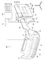
- FIG. 1 is a perspective view showing a configuration of a vehicle interior / exterior structure according to a first embodiment of the present invention.
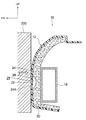
- FIG. 2 is a cross-sectional view taken along line F2-F2 of FIG.
- FIG. 3 is a cross-sectional view taken along line F3-F3 of FIG.
- FIG. 3 is a side cross-sectional view corresponding to FIG. 2, showing a state in which a collision body collides with the front bumper cover shown in FIG. 1.
- FIG. 4 is a side cross-sectional view corresponding to FIG. 3, showing a state in which a collision body collides with the front bumper cover shown in FIG. 1.
- It is a perspective view which shows the structure of the vehicle interior / exterior structure which concerns on 2nd embodiment of this invention.
- FIG. 7 is a cross-sectional view taken along line F7-F7 of FIG.
- FIG. 7 is a cross-sectional view taken along line F8-F8 of FIG.
- FIG. 10 is a cross-sectional view taken along line F10-F10 of FIG.
- FIG. 12 is a cross-sectional view taken along line F12-F12 of FIG. It is a perspective view which shows the structure of the vehicle interior / exterior structure which concerns on 5th embodiment of this invention.
- FIG. 2 shows the structure of the vehicle interior / exterior structure which concerns on 8th embodiment of this invention.
- an arrow UP, an arrow FR, and an arrow OUT shown in each figure indicate the vehicle vertical direction upper side, the vehicle front-rear direction front side, and the vehicle width direction outer side (left side), respectively.
- the vehicle interior / exterior structure 10 includes a front bumper cover 12 as a vehicle interior / exterior member, a pressure sensor 14, and a control unit 16 as a control unit. I have.
- the front bumper cover 12 is formed in a longitudinal shape in the vehicle width direction, and covers the bumper reinforcement 18 from the front side of the vehicle.
- the front bumper cover 12 includes a main body 20 and a skin material 22.
- the main body 20 is made of, for example, a foam material made of resin such as urethane, and is supported by a vehicle body such as a bumper reinforcement 18 or other body frame member (not shown).
- the front end portion 24 of the main body portion 20 is formed in a convex curved surface that is convex toward the front side of the vehicle, and the top portion 24 ⁇ / b> A as the outermost portion of the front end portion 24 has a vehicle outer side ( A recess 26 is formed in the front side of the vehicle.
- the recess 26 is formed in a longitudinal shape along the longitudinal direction of the front bumper cover 12 and is formed over the longitudinal direction of the front bumper cover 12.
- the skin material 22 is formed of an elastic material such as a painted resin film, for example, and covers the main body 20 from the front side of the vehicle so as to close the opening of the recess 26.
- the skin material 22 is in close contact with the main body 20 without any gaps, for example, by welding or the like.
- the skin material 22 closes the opening of the recess 26, so that a sealed space 28 is formed between the main body portion 20 and the skin material 22.
- the pressure sensor 14 shown in FIGS. 1 and 3 is connected to the above-described space portion 28 and the throttle portion 30 and is configured to output a signal corresponding to the internal pressure of the space portion 28 to the control unit 16. ing.
- the space portion 28 is formed with a substantially constant cross section, and the throttle portion 30 is formed with a cross section smaller than the space portion 28.
- the control unit 16 is based on a signal output from the pressure sensor 14, a signal output from the vehicle speed sensor 32, etc., and a front collision occupant protection device 34 provided in the vehicle shown in FIG. 1.
- the pedestrian protection device 36 is activated.
- the control unit 16 determines whether or not a front collision has occurred in the vehicle based on a signal output from the pressure sensor 14, a signal output from the vehicle speed sensor 32, or the like.
- the control unit 16 determines that a front collision has occurred in the vehicle, and in other cases, it is determined that no front collision has occurred in the vehicle.
- control unit 16 determines that a front collision has occurred in the vehicle, an operation signal is output from the control unit 16 to the occupant protection device 34 and the pedestrian protection device 36, and the occupant protection device 34 and The pedestrian protection device 36 is activated.
- an operation signal may be output from the control unit 16 to only one of the occupant protection device 34 and the pedestrian protection device 36, and the occupant protection device 34 and the pedestrian protection device may be output from the control unit 16.
- An activation signal may be output to both of the three.
- the front collision occupant protection device 34 and the pedestrian protection device 36 provided in the vehicle can be operated.
- a space 28 for detecting the collision of the colliding body is formed between the body portion 20 supported by the vehicle body such as the bumper reinforcement 18 and other vehicle body skeleton members (not shown) and the skin material 22. ing. Therefore, even if a member for receiving a force such as a vehicle skeleton member or a vehicle reinforcing member is not disposed behind the space portion 28, when a collision object collides with the front bumper cover 12, a reaction force is applied from the main body portion 20. As a result, the space 28 can be compressed and deformed. Thereby, the freedom degree of the setting position of the space part 28, ie, the setting position of the front collision detection area, can be improved.
- the bumper reinforcement 18 is disposed behind the space portion 28.
- the space portion 28 needs to be set at a position where the bumper reinforcement 18 is disposed behind the space portion 28. Absent.
- the main body portion 20 is formed of the foam material, the position of the space portion 28 can be freely set. Therefore, the degree of freedom of the setting position of the front collision detection area can be further improved.
- the space 28 is formed in a longitudinal shape, the front collision detection area can be enlarged.
- a front collision detection region can be set along the longitudinal direction of the front bumper cover 12.
- the connecting portion that connects the space portion 28 and the pressure sensor 14 is configured by the throttle portion 30 and the pressure is increased by the throttle portion 30, the pressure detection accuracy by the pressure sensor 14 can be improved.
- the space 28 is formed at the outermost part of the front bumper cover 12, that is, at the top 24 ⁇ / b> A at the front end 24 of the main body 20, the collision with the front bumper cover 12 is detected with higher accuracy. be able to.
- the space 28 is formed between the main body 20 and the skin material 22 and a dedicated chamber member or the like for detecting a collision is not required, the weight, size, and cost can be reduced. can do.
- the vehicle interior / exterior structure 40 according to the second embodiment of the present invention shown in FIGS. 6 to 8 has a configuration changed as follows with respect to the vehicle interior / exterior structure 10 according to the first embodiment described above.
- the main body portion 20 is formed with a concave portion 46 positioned at the lower portion of the front bumper cover 12 in addition to the above-described concave portion 26 positioned at the upper portion of the front bumper cover 12.
- the recess 46 is open to the front side of the vehicle, like the recess 26 described above.
- the recess 46 is formed in a longitudinal shape along the longitudinal direction of the front bumper cover 12 and is formed along the longitudinal direction of the front bumper cover 12. Further, the concave portion 46 is formed at the outermost portion (frontmost portion) in the lower portion of the main body portion 20, and both end sides thereof are bent toward the concave portion 26 and communicated with the concave portion 26.
- the front bumper cover 12 is formed with a sealed space 48 that communicates with the space 28 described above between the main body 20 and the skin material 22.
- the collision body 200 collides with the upper part of the front bumper cover 12 or the collision object 202 collides with the lower part of the front bumper cover 12.
- the portion 28 or the space portion 48 is compressed and deformed, the internal pressure of these space portions 28 and 48 increases.
- a signal corresponding to the internal pressure of the space portions 28 and 48 is output from the pressure sensor 14 to the control unit 16.
- control unit 16 determines that a front collision has occurred in the vehicle, an operation signal is sent from the control unit 16 to the occupant protection device 34 and the pedestrian protection device 36 as in the case of the first embodiment described above. In response to this, the occupant protection device 34 and the pedestrian protection device 36 are activated.
- a collision object collides with the upper part of the front bumper cover 12 or a collision object collides with the lower part of the front bumper cover 12. Even when one of them is compressed and deformed, the internal pressure of the space portions 28 and 48 can be detected by the common pressure sensor 14. Therefore, since it is not necessary to use a plurality of pressure sensors 14, the front collision detection area can be expanded while suppressing an increase in cost.
- the vehicle interior / exterior structure 50 includes a side door 52 as a vehicle interior / exterior member, a pressure sensor 54, and a control unit 56 as a control unit. And a hollow member 57.
- the side door 52 is provided on the side surface portion of the vehicle and is formed in a longitudinal shape in the vehicle front-rear direction.
- the side door 52 includes a main body portion 60 and a skin material 62.
- the main body 60 is made of, for example, a resin foam such as urethane, and its front end is fixed to the front pillar 58 so as to be rotatable.
- the main body 60 is fixed to the center pillar 59 when the side door 52 is closed.
- the outer portion 64 of the main body portion 60 is formed in a convex curved surface shape that protrudes outward of the vehicle.
- the skin material 62 is formed of an elastic material such as a coated resin film, for example, and covers the main body 60 from the outside of the vehicle.
- the hollow member 57 is formed of an elastic material made of resin, and is provided between the main body 60 and the skin material 62 in a state of being buried in the main body 60. Further, the hollow member 57 is disposed at the top 64 ⁇ / b> A as the outermost part in the outer side part 64.
- the hollow member 57 connects a pair of hollow portions 57A, 57B formed in a longitudinal shape along the vehicle longitudinal direction and a pair of hollow portions 57A, 57B extending in the vehicle vertical direction.
- the connecting portion 57 ⁇ / b> C is configured.
- the pair of hollow portions 57 ⁇ / b> A and 57 ⁇ / b> B are formed along the longitudinal direction of the side door 52.
- space portions 68A and 68B are formed inside the hollow portions 57A and 57B, and a communication path 68C is formed inside the connecting portion.
- the spaces 68A and 68B are communicated with each other through the communication path 68C.
- the pressure sensor 54 is connected to the space portion 68A and the throttle portion 70 described above, and is configured to output a signal corresponding to the internal pressure of the space portions 68A and 68B to the control unit 56.
- the space portions 68A and 68B are formed with a substantially constant cross section, and the throttle portion 70 is formed with a cross section smaller than the space portions 68A and 68B.
- control unit 56 operates a side collision occupant protection device 74 provided in the vehicle based on a signal output from the pressure sensor 54, a signal output from the vehicle speed sensor 32, or the like. Has been.
- the pressure value indicated by the signal output from the pressure sensor 54 exceeds a predetermined threshold value
- the vehicle speed value indicated by the signal output from the vehicle speed sensor 32 exceeds a predetermined threshold value.
- the control unit 56 it is determined that a side collision has occurred in the vehicle. Otherwise, it is determined that no side collision has occurred in the vehicle.
- control unit 56 determines that a side collision has occurred in the vehicle, an operation signal is output from the control unit 56 to the occupant protection device 74, and the occupant protection device 74 is operated accordingly.
- the side collision occupant protection device 74 provided in the vehicle can be operated.
- the space portions 68A and 68B for detecting the collision of the colliding body are formed inside a hollow member 57 provided between the main body portion 60 and the skin material 62. Therefore, even if a member that receives a force such as a vehicle skeleton member or a vehicle reinforcing member is not disposed behind the space portions 68A and 68B, the collision body collides with a portion of the side door 52 where the space portions 68A and 68B are located. In this case, since the reaction force can be obtained from the main body portion 60, the space portions 68A and 68B can be compressed and deformed. Thereby, the freedom degree of the setting position of space part 68A, 68B, ie, the setting position of a side collision detection area, can be improved.
- the main body 60 is formed of a foam material, the positions of the spaces 68A and 68B can be freely set. Accordingly, the degree of freedom of the set position of the side collision detection area can be further improved.
- the side collision detection region can be enlarged.
- a side collision detection region can be set along the longitudinal direction of the side door 52.
- the connecting portion that connects the space 68A and the pressure sensor 54 is constituted by the throttle portion 70, and the pressure is increased by the throttle portion 70, the pressure detection accuracy by the pressure sensor 54 can be improved.
- the space portions 68A and 68B are formed at the outermost portion of the side door 52, that is, the top portion 64A of the outer side portion 64 of the main body portion 60, it is detected more accurately that the colliding body has collided with the side door 52. be able to.
- the space portions 68A and 68B are formed in a portion close to the skin material 62, the collision detection accuracy can be improved.
- the space portions 68A and 68B may be configured by the concave portions and the skin material 62 formed in the main body portion 60, as in the first embodiment described above.
- the vehicle interior / exterior structure 80 according to the fourth embodiment of the present invention has the following configuration with respect to the vehicle interior / exterior structure 50 according to the third embodiment described above.
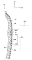
- the main body portion 60 is formed with a recess 86 at a position outside the top portion 64 ⁇ / b> A in the outer portion 64.
- the recess 86 opens to the outside of the vehicle.
- the skin material 62 is in close contact with the main body portion 60 by, for example, welding.
- the skin material 62 closes the opening of the recess 86, so that a sealed space 88 is formed between the main body 60 and the skin material 62.
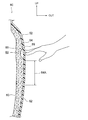
- the portion of the skin material 62 that closes the opening of the concave portion 86, that is, the portion of the space portion 88 outside the vehicle is configured as an operation portion 89.
- the operation unit 89 has the same size as a conventional door knob.
- the outer side portion of the side door 52 including the operation portion 89 has a flat configuration without a protruding portion like a conventional door knob.
- the pressure sensor 84 shown in FIG. 11 is connected to the above-described space portion 88 and the throttle portion 90, and is configured to output a signal corresponding to the internal pressure of the space portion 88 to the control unit 96.
- the space portion 88 is formed with a substantially constant cross section, and the throttle portion 90 is formed with a cross section smaller than the space portion 88.
- control unit 96 releases the lock between the side door 52 serving as the opening / closing body and the vehicle body based on a signal output from the pressure sensor 84, a signal output from the vehicle speed sensor 32, or the like.
- An opening / closing device 94 that opens and closes the device 92 and the side door 52 is operated.
- the control unit 96 determines whether or not the operation unit 89 has been pressed by the operator based on a signal output from the pressure sensor 84, a signal output from the vehicle speed sensor 32, or the like.
- the control unit 96 determines that the operation unit 89 has been pressed by the operator. Otherwise, it is determined that the operation unit 89 has not been pressed by the operator.
- the unlocking device 92 is activated and the side door 52 can be opened, or Then, the unlocking device 92 and the opening / closing device 94 are operated, and the side door 52 is automatically opened.
- the operation portion 89 is pressed by the operator while the side door 52 is in the open state, the opening / closing device 94 is activated and the side door 52 is automatically closed.
- an operation signal may be output from the control unit 96 to only one of the unlocking device 92 and the opening / closing device 94 when the operation unit 89 is pressed by the operator.
- the lock release device 92 and the opening / closing device 94 can be operated.
- the space part 88 is formed in the position outside the top part 64A in the outer part 64, the contact body suddenly contacts the outermost part (part where the top part 64A is located) of the side door 52.
- the operation of the unlocking device 92 and the opening / closing device 94 can be suppressed.
- the outer side portion of the side door 52 including the operation portion 89 has a flat structure without a projection like a conventional door knob, the appearance and aerodynamic characteristics of the side door 52 can be improved.
- the operation unit 89 can be set at an arbitrary position of the side door 52, the degree of freedom of the setting position of the operation unit 89 can be improved.
- main-body part 60 was formed with the foam material, you may be formed with the hard resin material.
- vehicle interior / exterior structure 80 may be applied to a vehicle interior member.
- a vehicle interior / exterior structure 100 includes a front bumper cover 12, a side door 52, a front fender panel 102 as a vehicle exterior part, a pressure sensor 14, and a first sensor.
- a pressure sensor 54 as a pressure sensor, a pressure sensor 84 as a second pressure sensor, a pressure sensor 104, and a control unit 106 as a control unit are provided.
- the front bumper cover 12 has the same configuration as that of the above-described second embodiment, and the side door 52 has a configuration in which the configurations of the above-described third and fourth embodiments are combined.
- the space portions 68A and 68B correspond to the first space portion in the present invention, and the space portion 88 corresponds to the second space portion in the present invention.
- the front fender panel 102 includes a main body 110 and a skin material 112, and has the same structure as the front bumper cover 12 and the side door 52 described above. That is, a space 118 is formed inside the front fender panel 102.
- the pressure sensor 104 is connected via the space portion 118 and the throttle portion 120 described above, and is configured to output a signal corresponding to the internal pressure of the space portion 118 to the control unit 106.
- the pressure sensors 14, 54, 84 are the same as those described in the second to fourth embodiments.
- control unit 106 is based on signals output from the pressure sensors 14, 54, 84, 104, signals output from the vehicle speed sensor 32, and the like. 34, 74, the pedestrian protection device 36, the lock release device 92, and the opening / closing device 94 are appropriately operated.
- the control unit 106 activates the occupant protection device 74 when it is determined that a side collision has occurred in the vehicle based on a signal output from the pressure sensor 104, a signal output from the vehicle speed sensor 32, or the like. It is supposed to be configured.
- the occupant protection devices 34 and 74 and the pedestrian protection device 36 can be operated accordingly.
- the operation unit 89 is pressed, the unlocking device 92 and the opening / closing device 94 can be appropriately operated.
- the space part 118 is formed in the front fender panel 102 and the side collision detection area is enlarged, the side collision detection accuracy can be improved.
- a vehicle interior / exterior structure 130 according to the sixth embodiment of the present invention shown in FIG. 14 includes a back door 132 as a vehicle exterior part and an opening / closing body, a rear bumper cover 133 as a vehicle exterior part, pressure sensors 134, 135A, 135B and a control unit 136 as a control unit.
- the back door 132 has a main body 140 and a skin material 142, and has the same structure as the side door 52 in the fourth embodiment described above.
- a space portion 138 is formed inside the back door 132, and a portion of the space portion 138 outside the vehicle is configured as an operation portion 139. Further, the space 138 is formed at a position deviating upward from the outermost part (the rearmost part) of the back door 132.
- the rear bumper cover 133 has the same structure as the above-described front bumper cover 12 (see FIG. 13), and space portions 148A and 148B independent from each other are formed therein.
- the pressure sensor 134 is connected to the space part 138 and the throttle part 150 described above, and is configured to output a signal corresponding to the internal pressure of the space part 138 to the control unit 136, respectively.
- the pressure sensors 135A and 135B are connected to the space portions 148A and 148B and the throttle portions 151A and 151B, respectively. Each of the pressure sensors 135A and 135B is configured to output a signal corresponding to the internal pressure of each of the space portions 148A and 148B to the control unit 136, respectively.
- the control unit 136 determines that the operation unit 139 has been pressed by the operator based on the signal output from the pressure sensor 134, the signal output from the vehicle speed sensor 32, or the like, as in the fourth embodiment described above. In this case, the lock release device 152 and the opening / closing device 154 are operated.
- the lock release device 152 and the opening / closing device 154 have the same configuration as the lock release device 92 and the opening / closing device 94 in the fourth embodiment described above.
- control unit 136 determines that a rear collision has occurred in the vehicle based on the signal output from the pressure sensors 135A and 135B, the signal output from the vehicle speed sensor 32, or the like, The occupant protection device 160 is activated.
- the occupant protection device 160 can be operated accordingly.
- the operation unit 139 is pressed, the unlocking device 92 and the opening / closing device 94 can be appropriately operated.
- the vehicle interior / exterior structure 160 according to the seventh embodiment of the present invention shown in FIG. 15 is modified in the following configuration from the vehicle interior / exterior structure 100 according to the fifth embodiment of the present invention described above.
- the space portion 68A and the space portion 88 are in communication. Further, the above-described pressure sensor 84 (see FIG. 13) is omitted from the side door 52.
- the control unit 166 is based on signals output from the pressure sensors 14, 54, 104, signals output from the vehicle speed sensor 32, etc., and occupant protection devices 34, 74, pedestrian protection device 36, lock
- the release device 92 and the opening / closing device 94 are configured to operate appropriately.
- the pressure value indicated by the signal output from the pressure sensor 54 at the time of a side collision is the operation unit 89 by the operator. Is greater than the pressure value indicated by the signal output from the pressure sensor 54 during the operation.
- control unit 166 based on the signal output from the pressure sensor 54, the signal output from the vehicle speed sensor 32, or the like, whether or not a side collision has occurred in the vehicle and the operation unit 89 is pressed by the operator. It is determined whether or not an operation has been performed.
- the control unit 166 determines that a side collision has occurred in the vehicle, and otherwise determines that no side collision has occurred in the vehicle.
- the pressure value indicated by the signal output from the pressure sensor 54 is less than the first threshold value and is smaller than the first threshold value and exceeds a predetermined second threshold value, and is output from the vehicle speed sensor 32.
- the vehicle speed value indicated by the signal is zero, it is determined in the control unit 166 that the operation unit 89 has been pressed by the operator, and in other cases, the operation unit 89 has been pressed by the operator. Judged not.
- control unit 166 determines that a side collision has occurred in the vehicle, an operation signal is output from the control unit 166 to the occupant protection device 74, and the occupant protection device 74 is operated accordingly.
- the side collision occupant protection device 74 provided in the vehicle can be operated.
- the operation unit 89 is pressed, the unlocking device 92 and the opening / closing device 94 can be appropriately operated.
- the pressure sensor 54 is used in common for the operation of the occupant protection device 74 and the operation of the lock release device 92 and the opening / closing device 94, an increase in cost can be suppressed.
- the space portion 88 communicates with the space portion 68A and the pressure sensor 54 is connected to the space portion 68A.
- the pressure sensor may be connected to the space portion 88. .
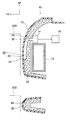
- the vehicle interior / exterior structure 160 according to the eighth embodiment of the present invention shown in FIG. 16 is a space on the vehicle front side inside the main body 20 with respect to the vehicle interior / exterior structure 10 according to the first embodiment of the present invention described above.
- the portion 28 is formed.
- a space portion may be formed inside the main body portion as in the eighth embodiment.
Landscapes
- Engineering & Computer Science (AREA)
- Mechanical Engineering (AREA)
- Body Structure For Vehicles (AREA)
- Vehicle Waterproofing, Decoration, And Sanitation Devices (AREA)
- Force Measurement Appropriate To Specific Purposes (AREA)
Abstract
Description
はじめに、本発明の第一実施形態について説明する。
次に、本発明の第二実施形態について説明する。
次に、本発明の第三実施形態について説明する。
次に、本発明の第四実施形態について説明する。
次に、本発明の第五実施形態について説明する。
次に、本発明の第六実施形態について説明する。
次に、本発明の第七実施形態について説明する。
次に、本発明の第八実施形態について説明する。
Claims (12)
- 車体に支持された樹脂製の本体部と、弾性材により形成されて前記本体部を覆う表皮材とを有すると共に、前記本体部と前記表皮材との間、又は、前記本体部の内部に空間部が形成された車両内外装部材と、
前記空間部の内部圧力に応じた信号を出力する圧力センサと、
を備えた車両内外装構造。 - 前記本体部は、発泡材により形成されている、
請求項1に記載の車両内外装構造。 - 前記空間部は、長手状に形成されている、
請求項1又は請求項2に記載の車両内外装構造。 - 前記車両内外装部材は、長手状に形成され、
前記空間部は、前記車両内外装部材の長手方向に亘って形成されている、
請求項3に記載の車両内外装構造。 - 前記空間部と前記圧力センサとを接続する接続部は、絞り部とされている、
請求項1~請求項4のいずれか一項に記載の車両内外装構造。 - 前記空間部は、互いに連通して複数形成され、
前記圧力センサは、前記複数の空間部のいずれか一つと接続されている、
請求項1~請求項5のいずれか一項に記載の車両内外装構造。 - 前記車両内外装部材は、車両外装部を構成し、
前記圧力センサから出力された信号に基づいて車両に衝突が生じたと判断した場合には、車両に備えられた乗員保護装置及び歩行者保護装置の少なくとも一方を作動させる制御部を備えた、
請求項1~請求項6のいずれか一項に記載の車両内外装構造。 - 前記空間部は、前記車両内外装部材の最外部に形成されている、
請求項7に記載の車両内外装構造。 - 前記車両内外装部材は、開閉体とされ、
前記車両内外装部材には、前記空間部の外側に操作部が形成され、
前記圧力センサから出力された信号に基づいて前記操作部が押圧操作されたと判断した場合には、前記開閉体と車体とのロック状態を解除するロック解除装置及び前記開閉体を開閉させる開閉装置の少なくとも一方を作動させる制御部を備えた、
請求項1~請求項6のいずれか一項に記載の車両内外装構造。 - 前記空間部は、前記開閉体の最外部から外れた位置に形成されている、
請求項9に記載の車両内外装構造。 - 前記空間部は、互いに連通して複数形成され、
前記圧力センサは、前記複数の空間部のいずれか一つと接続され、
前記車両内外装部材は、サイドドアとされると共に、前記複数の空間部のいずれか一つ又は他の一つの車両外側に操作部が形成された構成とされ、
前記圧力センサから出力された信号が示す圧力値が予め定められた第一閾値を超えていることを条件に、車両に側突が生じたと判断した場合には、車両に備えられた側突用の乗員保護装置を作動させ、前記圧力センサから出力された信号が示す圧力値が前記第一閾値未満で且つ前記第一閾値よりも小さく予め定められた第二閾値を超えていることを条件に、前記操作部が押圧操作されたと判断した場合には、前記サイドドアと車体とのロック状態を解除するロック解除装置及び前記サイドドアを開閉させる開閉装置の少なくとも一方を作動させる制御部を備えた、
請求項1~請求項6のいずれか一項に記載の車両内外装構造。 - 前記空間部は、互いに独立して形成された第一空間部及び第二空間部を有し、
前記圧力センサは、前記第一空間部の内部圧力に応じた信号を出力する第一圧力センサと、前記第二空間部の内部圧力に応じた信号を出力する第二圧力センサとを有し、
前記車両内外装部材は、サイドドアとされると共に、前記第二空間部の車両外側に操作部が形成された構成とされ、
前記第一圧力センサから出力された信号に基づいて車両に側突が生じたと判断した場合には、車両に備えられた側突用の乗員保護装置を作動させ、前記第二圧力センサから出力された信号に基づいて前記操作部が押圧操作されたと判断した場合には、前記サイドドアと車体とのロック状態を解除するロック解除装置及び前記サイドドアを開閉させる開閉装置の少なくとも一方を作動させる制御部を備えた、
請求項1~請求項5のいずれか一項に記載の車両内外装構造。
Priority Applications (5)
| Application Number | Priority Date | Filing Date | Title |
|---|---|---|---|
| US13/638,128 US8942891B2 (en) | 2010-04-01 | 2010-04-01 | Vehicle interior-exterior structure |
| CN201080065833.6A CN102892637B (zh) | 2010-04-01 | 2010-04-01 | 车辆内外装饰结构 |
| JP2012509198A JP5459391B2 (ja) | 2010-04-01 | 2010-04-01 | 車両内外装構造 |
| PCT/JP2010/056012 WO2011125147A1 (ja) | 2010-04-01 | 2010-04-01 | 車両内外装構造 |
| DE112010005436T DE112010005436T5 (de) | 2010-04-01 | 2010-04-01 | Fahrzeug-Innen-Aussen-Struktur |
Applications Claiming Priority (1)
| Application Number | Priority Date | Filing Date | Title |
|---|---|---|---|
| PCT/JP2010/056012 WO2011125147A1 (ja) | 2010-04-01 | 2010-04-01 | 車両内外装構造 |
Publications (1)
| Publication Number | Publication Date |
|---|---|
| WO2011125147A1 true WO2011125147A1 (ja) | 2011-10-13 |
Family
ID=44762135
Family Applications (1)
| Application Number | Title | Priority Date | Filing Date |
|---|---|---|---|
| PCT/JP2010/056012 Ceased WO2011125147A1 (ja) | 2010-04-01 | 2010-04-01 | 車両内外装構造 |
Country Status (5)
| Country | Link |
|---|---|
| US (1) | US8942891B2 (ja) |
| JP (1) | JP5459391B2 (ja) |
| CN (1) | CN102892637B (ja) |
| DE (1) | DE112010005436T5 (ja) |
| WO (1) | WO2011125147A1 (ja) |
Cited By (4)
| Publication number | Priority date | Publication date | Assignee | Title |
|---|---|---|---|---|
| CN102658807A (zh) * | 2012-05-14 | 2012-09-12 | 力帆实业(集团)股份有限公司 | 轿车防侧撞装置 |
| JP2015003589A (ja) * | 2013-06-20 | 2015-01-08 | 株式会社デンソー | 車両用制御装置 |
| US20150274118A1 (en) * | 2014-03-31 | 2015-10-01 | Ford Global Technologies, Llc | Impact tubing for pedestrian protection sensor for automotive vehicle |
| JP2016020133A (ja) * | 2014-07-14 | 2016-02-04 | トヨタ自動車株式会社 | 歩行者衝突検知センサを備えた車両用バンパ構造 |
Families Citing this family (13)
| Publication number | Priority date | Publication date | Assignee | Title |
|---|---|---|---|---|
| DE102013205490A1 (de) * | 2013-03-27 | 2014-10-02 | Bayerische Motoren Werke Aktiengesellschaft | Stoßfängeranordnung für einen Personenkraftwagen sowie Personenkraftwagen mit einer solchen Stoßfängeranordnung |
| DE102013208709A1 (de) * | 2013-05-13 | 2014-11-13 | Bayerische Motoren Werke Aktiengesellschaft | Verfahren zum Ermitteln von Eingangsdaten einer Fahrerassistenzeinheit |
| DE102013016239B4 (de) * | 2013-09-28 | 2021-06-17 | Daimler Ag | Fahrzeug |
| CN103587486A (zh) * | 2013-11-01 | 2014-02-19 | 安徽工贸职业技术学院 | 一种汽车防撞缓冲装置 |
| US20150368082A1 (en) * | 2014-06-23 | 2015-12-24 | The Boeing Company | Collision avoidance system for scissor lift |
| EP3197705B1 (de) * | 2014-09-25 | 2023-04-05 | Continental Automotive Technologies GmbH | In abstandssensoren integrierte lokalisierung von ladespulen |
| JP6107784B2 (ja) * | 2014-10-10 | 2017-04-05 | トヨタ自動車株式会社 | 歩行者衝突検知センサを備えた車両用バンパ構造 |
| JP6256427B2 (ja) * | 2015-08-10 | 2018-01-10 | トヨタ自動車株式会社 | 歩行者衝突検知センサを備えた車両用バンパ構造 |
| US10029735B2 (en) * | 2016-01-29 | 2018-07-24 | Nissan North America, Inc. | Vehicle body structure |
| DE102016122288A1 (de) * | 2016-11-21 | 2018-05-24 | Dr. Ing. H.C. F. Porsche Aktiengesellschaft | Fahrzeugfrontstruktur |
| US10137850B2 (en) * | 2017-01-11 | 2018-11-27 | Toyota Motor Engineering & Manufacturing North America, Inc. | Vehicle bumper collision indicator |
| WO2022002058A1 (zh) * | 2020-06-30 | 2022-01-06 | 北京三快在线科技有限公司 | 车身外壳和具有该车身外壳的车辆 |
| JP7812254B2 (ja) * | 2022-03-08 | 2026-02-09 | 株式会社Subaru | 衝突検知装置 |
Citations (8)
| Publication number | Priority date | Publication date | Assignee | Title |
|---|---|---|---|---|
| JPS59146247U (ja) * | 1983-03-22 | 1984-09-29 | 日本電気ホームエレクトロニクス株式会社 | 自動車の衝激防止用プロテクタ |
| JPH11310095A (ja) * | 1998-02-24 | 1999-11-09 | Toyota Central Res & Dev Lab Inc | 車両用衝突判別装置 |
| JP2001236869A (ja) * | 2000-02-22 | 2001-08-31 | Tokyo Sensor:Kk | 流体スイッチ装置 |
| JP2006117157A (ja) * | 2004-10-22 | 2006-05-11 | Denso Corp | 車両用障害物判別装置 |
| JP2006232126A (ja) * | 2005-02-25 | 2006-09-07 | Denso Corp | 乗員保護装置の起動装置 |
| JP2008525255A (ja) * | 2004-12-24 | 2008-07-17 | ダイムラー・アクチェンゲゼルシャフト | 自動車の衝突検出用の装置 |
| JP2009023410A (ja) * | 2007-07-17 | 2009-02-05 | Denso Corp | 衝突検出装置 |
| JP2009220787A (ja) * | 2008-03-18 | 2009-10-01 | Denso Corp | 衝突検知装置 |
Family Cites Families (11)
| Publication number | Priority date | Publication date | Assignee | Title |
|---|---|---|---|---|
| FR2694778B1 (fr) | 1992-08-11 | 1995-04-14 | Smh Management Services Ag | Dispositif de sécurité destiné à l'ouverture et/ou à la fermeture de porte notamment pour un véhicule automobile. |
| JP2001163130A (ja) | 1999-12-09 | 2001-06-19 | Araco Corp | 電動車両用非常停止装置 |
| US7422086B2 (en) * | 2003-03-18 | 2008-09-09 | Ford Global Technologies, Llc | Vehicle impact sensor using both accelerometer and pressure sensing for side impact detection |
| JP2005098016A (ja) * | 2003-09-26 | 2005-04-14 | Matsushita Electric Ind Co Ltd | ドアハンドル装置及びこれを備えたキーレスエントリー装置 |
| US7498927B1 (en) * | 2005-08-10 | 2009-03-03 | Fuji Jukogyo Kabushiki Kaisha | Security alarm |
| JP4816187B2 (ja) | 2006-03-27 | 2011-11-16 | 株式会社デンソー | 衝突検知手段 |
| JP4466690B2 (ja) * | 2007-07-17 | 2010-05-26 | 株式会社デンソー | 衝突検出装置 |
| JP4497182B2 (ja) * | 2007-07-23 | 2010-07-07 | 株式会社デンソー | 衝突検出装置 |
| JP4816665B2 (ja) | 2008-03-18 | 2011-11-16 | 株式会社デンソー | 車両用衝突検知装置 |
| DE102008017246B4 (de) | 2008-04-04 | 2018-06-28 | Dr. Ing. H.C. F. Porsche Aktiengesellschaft | Anordnung zur Aufprallerkennung |
| DE102009005525A1 (de) | 2008-07-03 | 2010-01-07 | Huf Hülsbeck & Fürst Gmbh & Co. Kg | Sicherheitssystem |
-
2010
- 2010-04-01 JP JP2012509198A patent/JP5459391B2/ja active Active
- 2010-04-01 DE DE112010005436T patent/DE112010005436T5/de active Granted
- 2010-04-01 CN CN201080065833.6A patent/CN102892637B/zh active Active
- 2010-04-01 WO PCT/JP2010/056012 patent/WO2011125147A1/ja not_active Ceased
- 2010-04-01 US US13/638,128 patent/US8942891B2/en active Active
Patent Citations (8)
| Publication number | Priority date | Publication date | Assignee | Title |
|---|---|---|---|---|
| JPS59146247U (ja) * | 1983-03-22 | 1984-09-29 | 日本電気ホームエレクトロニクス株式会社 | 自動車の衝激防止用プロテクタ |
| JPH11310095A (ja) * | 1998-02-24 | 1999-11-09 | Toyota Central Res & Dev Lab Inc | 車両用衝突判別装置 |
| JP2001236869A (ja) * | 2000-02-22 | 2001-08-31 | Tokyo Sensor:Kk | 流体スイッチ装置 |
| JP2006117157A (ja) * | 2004-10-22 | 2006-05-11 | Denso Corp | 車両用障害物判別装置 |
| JP2008525255A (ja) * | 2004-12-24 | 2008-07-17 | ダイムラー・アクチェンゲゼルシャフト | 自動車の衝突検出用の装置 |
| JP2006232126A (ja) * | 2005-02-25 | 2006-09-07 | Denso Corp | 乗員保護装置の起動装置 |
| JP2009023410A (ja) * | 2007-07-17 | 2009-02-05 | Denso Corp | 衝突検出装置 |
| JP2009220787A (ja) * | 2008-03-18 | 2009-10-01 | Denso Corp | 衝突検知装置 |
Cited By (6)
| Publication number | Priority date | Publication date | Assignee | Title |
|---|---|---|---|---|
| CN102658807A (zh) * | 2012-05-14 | 2012-09-12 | 力帆实业(集团)股份有限公司 | 轿车防侧撞装置 |
| JP2015003589A (ja) * | 2013-06-20 | 2015-01-08 | 株式会社デンソー | 車両用制御装置 |
| US20150274118A1 (en) * | 2014-03-31 | 2015-10-01 | Ford Global Technologies, Llc | Impact tubing for pedestrian protection sensor for automotive vehicle |
| US9221414B2 (en) * | 2014-03-31 | 2015-12-29 | Ford Global Technologies, Llc | Impact tubing for pedestrian protection sensor for automotive vehicle |
| RU2658531C2 (ru) * | 2014-03-31 | 2018-06-21 | Форд Глобал Технолоджис, ЛЛК | Система для минимизации травм объекта при столкновении с транспортным средством |
| JP2016020133A (ja) * | 2014-07-14 | 2016-02-04 | トヨタ自動車株式会社 | 歩行者衝突検知センサを備えた車両用バンパ構造 |
Also Published As
| Publication number | Publication date |
|---|---|
| JPWO2011125147A1 (ja) | 2013-07-08 |
| DE112010005436T5 (de) | 2013-04-04 |
| JP5459391B2 (ja) | 2014-04-02 |
| US20130013156A1 (en) | 2013-01-10 |
| CN102892637B (zh) | 2015-09-16 |
| US8942891B2 (en) | 2015-01-27 |
| CN102892637A (zh) | 2013-01-23 |
Similar Documents
| Publication | Publication Date | Title |
|---|---|---|
| JP5459391B2 (ja) | 車両内外装構造 | |
| US7614685B2 (en) | Vehicle side door structure | |
| US8491039B2 (en) | Vehicular rear impact sensor mounting structure | |
| US8033356B2 (en) | External airbag system of vehicle | |
| JP3553617B2 (ja) | 衝撃検知装置 | |
| WO2004058559A1 (ja) | 車両のフロントボデー構造 | |
| EP0807559B1 (en) | Collision sensing apparatus | |
| US9776664B2 (en) | Impact transmission structure | |
| JP5170140B2 (ja) | 車両用衝突検知装置 | |
| JP5205882B2 (ja) | 車両用ニーエアバッグ装置 | |
| JP5045313B2 (ja) | 車両用ニーエアバッグ装置 | |
| US6969110B2 (en) | Impact load transfer element | |
| JP4586505B2 (ja) | 車両衝突状態判断装置 | |
| JP5765243B2 (ja) | 車両側面衝突検出機構及び乗員保護システム | |
| JP2001080451A (ja) | 側突用エアバッグセンサの取付構造 | |
| JP2022190406A (ja) | 車両用バンパー | |
| JP7436963B2 (ja) | 車両のサイドドア構造及び衝突検出システム | |
| JP3716663B2 (ja) | エアバッグセンサの配設構造 | |
| JP5994666B2 (ja) | 歩行者衝突検出装置を備えた車両用バンパ | |
| JP5223251B2 (ja) | 車両の乗員保護装置 | |
| JP2008222095A (ja) | 側突センサ取付け構造 | |
| JP2513869Y2 (ja) | 車体側部のエアバッグ取付構造 | |
| JP2007196946A (ja) | 車両用衝突検出装置 | |
| JP6485246B2 (ja) | 車両用ドア | |
| GB2517139A (en) | A side door for a motor vehicle |
Legal Events
| Date | Code | Title | Description |
|---|---|---|---|
| WWE | Wipo information: entry into national phase |
Ref document number: 201080065833.6 Country of ref document: CN |
|
| 121 | Ep: the epo has been informed by wipo that ep was designated in this application |
Ref document number: 10849391 Country of ref document: EP Kind code of ref document: A1 |
|
| DPE2 | Request for preliminary examination filed before expiration of 19th month from priority date (pct application filed from 20040101) | ||
| WWE | Wipo information: entry into national phase |
Ref document number: 2012509198 Country of ref document: JP |
|
| WWE | Wipo information: entry into national phase |
Ref document number: 13638128 Country of ref document: US |
|
| WWE | Wipo information: entry into national phase |
Ref document number: 1120100054363 Country of ref document: DE Ref document number: 112010005436 Country of ref document: DE |
|
| 122 | Ep: pct application non-entry in european phase |
Ref document number: 10849391 Country of ref document: EP Kind code of ref document: A1 |