WO2011108215A1 - 基板収納装置 - Google Patents
基板収納装置 Download PDFInfo
- Publication number
- WO2011108215A1 WO2011108215A1 PCT/JP2011/000942 JP2011000942W WO2011108215A1 WO 2011108215 A1 WO2011108215 A1 WO 2011108215A1 JP 2011000942 W JP2011000942 W JP 2011000942W WO 2011108215 A1 WO2011108215 A1 WO 2011108215A1
- Authority
- WO
- WIPO (PCT)
- Prior art keywords
- storage device
- substrate storage
- air supply
- substrate
- exhaust
- Prior art date
- Legal status (The legal status is an assumption and is not a legal conclusion. Google has not performed a legal analysis and makes no representation as to the accuracy of the status listed.)
- Ceased
Links
Images





Classifications
-
- H—ELECTRICITY
- H10—SEMICONDUCTOR DEVICES; ELECTRIC SOLID-STATE DEVICES NOT OTHERWISE PROVIDED FOR
- H10P—GENERIC PROCESSES OR APPARATUS FOR THE MANUFACTURE OR TREATMENT OF DEVICES COVERED BY CLASS H10
- H10P72/00—Handling or holding of wafers, substrates or devices during manufacture or treatment thereof
- H10P72/10—Handling or holding of wafers, substrates or devices during manufacture or treatment thereof using carriers specially adapted therefor, e.g. front opening unified pods [FOUP]
- H10P72/19—Handling or holding of wafers, substrates or devices during manufacture or treatment thereof using carriers specially adapted therefor, e.g. front opening unified pods [FOUP] closed carriers
- H10P72/1906—Handling or holding of wafers, substrates or devices during manufacture or treatment thereof using carriers specially adapted therefor, e.g. front opening unified pods [FOUP] closed carriers specially adapted for containing masks, reticles or pellicles
-
- H—ELECTRICITY
- H10—SEMICONDUCTOR DEVICES; ELECTRIC SOLID-STATE DEVICES NOT OTHERWISE PROVIDED FOR
- H10P—GENERIC PROCESSES OR APPARATUS FOR THE MANUFACTURE OR TREATMENT OF DEVICES COVERED BY CLASS H10
- H10P72/00—Handling or holding of wafers, substrates or devices during manufacture or treatment thereof
- H10P72/10—Handling or holding of wafers, substrates or devices during manufacture or treatment thereof using carriers specially adapted therefor, e.g. front opening unified pods [FOUP]
-
- B—PERFORMING OPERATIONS; TRANSPORTING
- B65—CONVEYING; PACKING; STORING; HANDLING THIN OR FILAMENTARY MATERIAL
- B65D—CONTAINERS FOR STORAGE OR TRANSPORT OF ARTICLES OR MATERIALS, e.g. BAGS, BARRELS, BOTTLES, BOXES, CANS, CARTONS, CRATES, DRUMS, JARS, TANKS, HOPPERS, FORWARDING CONTAINERS; ACCESSORIES, CLOSURES, OR FITTINGS THEREFOR; PACKAGING ELEMENTS; PACKAGES
- B65D85/00—Containers, packaging elements or packages, specially adapted for particular articles or materials
-
- G—PHYSICS
- G03—PHOTOGRAPHY; CINEMATOGRAPHY; ANALOGOUS TECHNIQUES USING WAVES OTHER THAN OPTICAL WAVES; ELECTROGRAPHY; HOLOGRAPHY
- G03F—PHOTOMECHANICAL PRODUCTION OF TEXTURED OR PATTERNED SURFACES, e.g. FOR PRINTING, FOR PROCESSING OF SEMICONDUCTOR DEVICES; MATERIALS THEREFOR; ORIGINALS THEREFOR; APPARATUS SPECIALLY ADAPTED THEREFOR
- G03F1/00—Originals for photomechanical production of textured or patterned surfaces, e.g., masks, photo-masks, reticles; Mask blanks or pellicles therefor; Containers specially adapted therefor; Preparation thereof
- G03F1/68—Preparation processes not covered by groups G03F1/20 - G03F1/50
- G03F1/82—Auxiliary processes, e.g. cleaning or inspecting
-
- H—ELECTRICITY
- H10—SEMICONDUCTOR DEVICES; ELECTRIC SOLID-STATE DEVICES NOT OTHERWISE PROVIDED FOR
- H10P—GENERIC PROCESSES OR APPARATUS FOR THE MANUFACTURE OR TREATMENT OF DEVICES COVERED BY CLASS H10
- H10P72/00—Handling or holding of wafers, substrates or devices during manufacture or treatment thereof
- H10P72/10—Handling or holding of wafers, substrates or devices during manufacture or treatment thereof using carriers specially adapted therefor, e.g. front opening unified pods [FOUP]
- H10P72/19—Handling or holding of wafers, substrates or devices during manufacture or treatment thereof using carriers specially adapted therefor, e.g. front opening unified pods [FOUP] closed carriers
- H10P72/1924—Handling or holding of wafers, substrates or devices during manufacture or treatment thereof using carriers specially adapted therefor, e.g. front opening unified pods [FOUP] closed carriers characterised by atmosphere control
- H10P72/1926—Handling or holding of wafers, substrates or devices during manufacture or treatment thereof using carriers specially adapted therefor, e.g. front opening unified pods [FOUP] closed carriers characterised by atmosphere control characterised by the presence of atmosphere modifying elements inside or attached to the closed carrier
-
- Y—GENERAL TAGGING OF NEW TECHNOLOGICAL DEVELOPMENTS; GENERAL TAGGING OF CROSS-SECTIONAL TECHNOLOGIES SPANNING OVER SEVERAL SECTIONS OF THE IPC; TECHNICAL SUBJECTS COVERED BY FORMER USPC CROSS-REFERENCE ART COLLECTIONS [XRACs] AND DIGESTS
- Y10—TECHNICAL SUBJECTS COVERED BY FORMER USPC
- Y10T—TECHNICAL SUBJECTS COVERED BY FORMER US CLASSIFICATION
- Y10T137/00—Fluid handling
- Y10T137/8593—Systems
- Y10T137/85978—With pump
- Y10T137/86035—Combined with fluid receiver
Definitions
- the present invention relates to a substrate storage apparatus for storing and transporting a substrate such as a mask blank.
- a lithography technique using a photomask In order to form a fine circuit pattern on a semiconductor wafer or FPD substrate, a lithography technique using a photomask is known.
- a fine circuit pattern is reduced and transferred onto a semiconductor wafer by exposing an electromagnetic wave of an exposure light source to a substrate such as a semiconductor wafer on which a resist film is formed through a photomask having a circuit pattern formed thereon. .
- Such a photomask forms a circuit pattern by repeating a plurality of processes such as film formation, chemical mechanical polishing (CMP), and cleaning on a substrate surface called a mask blank in which a light-shielding film is formed on a light-transmitting substrate.
- CMP chemical mechanical polishing
- a mask blank in which a light-shielding film is formed on a light-transmitting substrate.
- Patent Document 1 As a storage container for storing, transporting and transporting such mask blanks cleanly, for example, those described in Patent Documents 1 and 2 below are known.
- the storage container described in Patent Document 1 has a ventilation hole provided with a filter at a corner of the container in order to prevent foreign substances from entering from the outside.
- the storage container described in Patent Document 2 introduces an inert gas into the container, diffuses it with a diffusion plate, and exhausts it in order to prevent the surface of the photomask or the like from changing with time.
- the present invention has been made in view of such problems, and an object of the present invention is to effectively prevent foreign matter from adhering to a stored substrate according to the use environment. It is to provide a substrate storage device.
- a substrate storage device for storing a substrate, an air supply unit for taking outside air into the substrate storage device, and an air supply unit facing the air supply unit.
- An exhaust portion disposed, a substrate mounting plate provided between the air supply portion and the exhaust portion, and having a communication hole communicating between them; an air supply filter provided in the air supply portion;
- a state sensor that detects a state inside the substrate storage device, a particle charging device, and a temperature control device, or a combination of two or more A substrate storage device is provided, wherein the substrate storage device is detachably provided.
- a substrate storage device for storing a substrate, wherein an air supply unit provided with an introduction port for introducing purge gas into the substrate storage device; An exhaust part disposed opposite to the air supply part, a substrate mounting plate provided between the air supply part and the exhaust part, and having a communication hole communicating therewith; and the air supply part or A fan provided in the exhaust unit, and a state sensor for detecting a state in the substrate storage device, a particle charging device, and a temperature control device, or a combination of two or more thereof, is detachably provided
- substrate storage apparatus characterized by this is provided.
- outside air is introduced from the air supply section through the filter by driving the fan, or purge gas is introduced from the introduction port and exhausted from the opposing exhaust section.
- purge gas is introduced from the introduction port and exhausted from the opposing exhaust section.
- the state sensor, the particle charging device, the temperature control device, or a combination thereof can be mounted in accordance with the use environment of the substrate storage device, so that foreign matter adheres without waste depending on the use environment.
- the prevention effect can be enhanced.
- the state sensor is, for example, any one of a temperature sensor, a charge sensor, a particle sensor, a vibration sensor, and a gas sensor, or a combination of two or more.
- a storage unit that stores the output of the state sensor and a control unit that determines whether or not the output of the state sensor stored in the storage unit exceeds a predetermined threshold value may be provided. If the output of the state sensor exceeds a predetermined threshold value, an abnormality has occurred, and it can be determined that foreign matter has adhered to the stored substrate.
- an outer container is provided so as to cover the substrate storage device, and a circulation path is formed between the substrate storage device and the outer container to return the exhaust from the exhaust unit to the air supply unit.
- a circulation path is formed between the substrate storage device and the outer container to return the exhaust from the exhaust unit to the air supply unit.
- an anti-vibration material can be provided between the substrate storage device and the outer container, and the circulation path can be formed between the anti-vibration materials. According to this, since the exhaust from the exhaust part returns to the air supply part through the circulation path, for example, it can be conveyed while maintaining the cleanliness in the outer container even in an environment outside the clean room.
- a side plate may be detachably provided between the air supply unit and the exhaust unit. According to this, for example, by removing the side plate, the substrate can be taken in and out from the side surface by the transfer arm or the like.
- a substrate storage device for storing a substrate, an air supply portion for taking outside air into the substrate storage device, and an air supply portion facing the air supply portion.
- the substrate mounting plate Provided on the air supply unit, the air supply unit and the exhaust unit, the substrate mounting plate having a communication hole communicating between them, and the air supply unit or the exhaust unit.
- a state sensor that detects a state in the substrate storage device, a particle charging device, and a temperature control device that warms the surface of the substrate, or a combination of two or more is detachably provided.
- a substrate storage device is provided in which an opening is provided between the exhaust unit and the air supply unit.
- the outside air is introduced from the air supply section through the filter by driving the fan, and is exhausted from the opposing exhaust section.
- a flow of air flowing from the air supply unit side to the exhaust unit side is formed around the substrate stored in the substrate storage device.
- the substrate can be easily put in and out from the opening on the side surface by a transfer arm or the like while preventing foreign matter from adhering to the substrate in the substrate storage device.
- the state sensor, the particle charging device, the temperature control device, or a combination thereof can be mounted in accordance with the use environment of the substrate storage device, so that foreign matter adheres without waste depending on the use environment.
- the prevention effect can be enhanced.
- an outer container is provided so as to cover the substrate storage device, and the outer container is provided with a closing plate that closes an opening between the exhaust portion and the air supply portion.
- a circulation path for returning the exhaust from the exhaust part to the air supply part may be formed between the outer container and the outer container.
- a vibration isolating material is provided between the substrate storage device and the outer container, and the circuit between the vibration isolating material is used as the circulation path.
- a vibration isolating material may be provided outside the substrate storage device or outside the outer container. According to this, for example, an impact when transported in an environment outside a clean room can be absorbed, so that even if a foreign substance adheres to the substrate storage device, it can be prevented from peeling off and adhering to the substrate.
- the present invention not only can foreign matter be effectively prevented from adhering to the substrate in the substrate storage device, but also a state sensor, a particle charging device, a temperature control device, or a combination thereof, depending on the use environment. Since it can be mounted, the effect of preventing foreign matter adhesion can be enhanced without waste according to the usage environment.
- FIG. 1 is an external perspective view showing a schematic configuration of a substrate storage device according to an embodiment of the present invention. It is a longitudinal cross-sectional view of the board
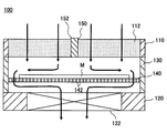
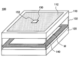
- FIG. 1 is a perspective view showing a configuration example of a substrate storage device according to the present embodiment
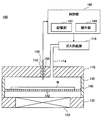
- FIG. 2 is a longitudinal sectional view of the substrate storage device.
- the appearance of the substrate storage apparatus 100 is box-shaped, and is configured so that a single mask blank M can be stored horizontally therein.
- the substrate storage apparatus 100 includes an air supply unit 110 that takes outside air into the inside, and an exhaust unit 120 that is provided opposite to the air supply unit 110 and exhausts the internal atmosphere.
- 1 shows an example in which the upper part of the substrate storage device 100 is configured by the air supply unit 110 and the lower part is configured by the exhaust unit 120.
- the configurations of the air supply unit 110 and the exhaust unit 120 are not limited to this.
- the air supply unit 110 and the exhaust unit 120 may be provided in part of the upper part and the lower part of the substrate storage device 100, respectively.
- a side wall 130 is provided between the air supply unit 110 and the exhaust unit 120 so as to surround the periphery of the substrate storage apparatus 100.
- the air supply unit 110 is provided with an air supply filter 112 that filters outside air taken into the substrate storage apparatus 100. By removing and taking in foreign matter contained in the outside air by the air supply filter 112, it is possible to prevent foreign matter from adhering to the mask blanks M in the substrate storage apparatus 100.
- Such an air supply filter 112 is composed of a particle removal filter that removes particles such as dust and dust contained in the outside air.
- the particle removal filter include a HEPA (High Efficiency Particulate Air Filter) filter and a ULPA (Ultra Low Penetration Air) filter.
- the exhaust unit 120 includes a fan 122 that exhausts the atmosphere in the substrate storage apparatus 100.
- a fan 122 that exhausts the atmosphere in the substrate storage apparatus 100.
- the case where one fan 122 is provided in the center of the exhaust part 120 is taken as an example.
- the number of fans 122 is not limited to the illustrated case, and two or more fans 122 may be provided.
- the fan 122 may be provided in the air supply unit 110. In this case, the fan 122 may be provided on the upper side of the air supply filter 112 or may be provided on the lower side.
- a substrate mounting plate 140 is provided between the air supply unit 110 and the exhaust unit 120.
- the mask blank M is placed on the upper part of the substrate placing plate 140.
- the substrate mounting plate 140 is provided so as to partition the internal space of the substrate storage device 100 into the air supply unit 110 side and the exhaust unit 120 side.
- the substrate mounting plate 140 is provided with a communication hole 142 that communicates the space on the air supply unit 110 side and the space on the exhaust unit 120 side.
- the substrate storage device 100 may be insufficient to form an air flow in the substrate storage device 100 as described above. For example, even if the foreign matter is minute, if it is charged or enters a large amount, the possibility of adhering to the mask blank M increases.
- the substrate storage apparatus 100 is provided with a state sensor for detecting an internal state, a particle charging device, a temperature control device, or a combination of two or more in a detachable manner, so as to suit the use environment.
- a state sensor for detecting an internal state
- a particle charging device for detecting an internal state
- a temperature control device for adjusting the temperature of the substrate storage apparatus 100 to the present embodiment.
- the substrate storage device 100 by providing a state sensor in the substrate storage device 100 and detecting the internal state, it is possible to determine whether or not the environment in which foreign matter is likely to adhere is determined.
- a particle charging device in the substrate storage device 100 to neutralize the foreign matter and the mask blank M or to control the charging polarity, it is possible to make it difficult for the foreign matter to adhere to the mask blank M.
- the substrate storage apparatus 100 equipped with the above-described state sensor, particle charging device, and temperature control device.
- the substrate storage apparatus 100 has a mounting hole 150 provided in the air supply unit 110, and a mounting part 152 provided in the state sensor, the particle charging device, and the temperature control device. It can be detachably mounted by attaching it to.
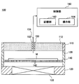
- FIG. 3 is a cross-sectional view showing a configuration example when only the state sensor 154 is mounted.
- FIG. 4 is a cross-sectional view showing a configuration example when the state sensor 154 and the particle charging device 156 are mounted in combination.
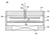
- FIG. 5 is a cross-sectional view showing a configuration example when the state sensor 154 and the temperature control device 158 are mounted in combination.
- the state sensor 154 is attached to the substrate storage device 100 by attaching the attachment portion 152 provided with the state sensor 154 to the attachment hole 150.
- the state sensor 154 detects the internal state of the substrate storage apparatus 100 (for example, temperature, charging degree, contamination degree, etc.). Examples of such a state sensor include a temperature sensor, a charging sensor, a particle sensor, a vibration sensor, and a gas sensor. These may be provided alone or in combination of two or more thereof.
- the temperature sensor detects the temperature of the inside of the substrate storage device 100, the mask blank M, and the like.
- the charge sensor detects the charge polarity and charge degree of foreign matter in the substrate storage device 100, mask blanks M, and the like.
- the particle sensor detects the amount of foreign matter in the substrate storage device 100.
- the vibration sensor detects large or fine vibrations. As the vibration sensor, an acceleration sensor may be used when detecting a large vibration, and an ultrasonic sensor may be used when detecting a small vibration.
- the state sensor 154 is connected to a control unit 160 that controls the entire substrate storage apparatus 100.
- the control unit 160 includes a storage unit 162, an operation unit 164, and the like.
- the storage unit 162 stores data detected from the state sensor 154 and the like.
- the operation unit 164 is provided with a power switch and the like.
- the control unit 160 determines whether foreign matter has adhered to the mask blanks M in the substrate storage device 100 and determines the usage environment of the substrate storage device 100. For example, when the internal state of the substrate storage device 100 such as the temperature and the charge degree changes, foreign matter easily adheres to the mask blanks M. Therefore, it is possible to determine whether or not foreign matter has adhered to the mask blank M by monitoring these internal states and detecting the change.
- control unit 160 when the control unit 160 takes in the output from the state sensor 154, the control unit 160 stores the output in the storage unit 162 and monitors the internal state of the substrate storage apparatus 100. When the output from the state sensor 154 exceeds a predetermined threshold value, it is determined that foreign matter is attached to the mask blank M.
- control unit 160 determines the usage environment of the substrate storage device 100 (for example, the usage environment in which foreign matter is charged, the usage environment in which the amount of foreign matter is large) based on the output from the state sensor 154, and the determination result is Accordingly, for example, it is determined whether or not the particle charging device 156 and the temperature control device 158 are to be mounted, which one is to be mounted, and which combination is to be mounted. For example, it is determined that the particle charging device 156 needs to be mounted in a usage environment in which a foreign object is charged, and the temperature control device 158 is determined to be mounted in a usage environment in which the amount of foreign matter is large. Note that this determination is not necessarily performed automatically, and the operator of the substrate storage device 100 may make the determination by looking at the determination result of the use environment.
- the particle charging device 156 is fixed to the mounting portion 152 so as to be spaced above the air supply filter 112 above the mask blank M.
- the mounting unit 152 is provided with a state sensor 154. According to this, both the state sensor 154 and the particle charging device 156 can be attached to the substrate storage device 100 by attaching the attachment portion 152 to the attachment hole 150.
- the particle charging device 156 can be composed of, for example, a soft X-ray source, a UV light source, an ionizer, or the like. By eliminating the charge inside the substrate storage device 100 with such a particle charging device 156, the charge of the foreign matter that has entered the substrate storage device 100 can be removed, so that it is effective that such foreign matter adheres to the mask blank M. Can be prevented.
- foreign matter may be charged with the same polarity as that of the mask blank M by generating ions with an ionizer. Thereby, it can prevent effectively that such a foreign material adheres to the mask blank M.
- a voltage having the same polarity as the foreign matter may be applied from the lower part of the mask blank M.
- the state sensor 154 may be a charge sensor, and the control unit 160 may detect the degree of charge, and the control unit 160 may control the output of the particle charging device 156 accordingly.
- the temperature control device 158 is fixed to the mounting portion 152 so as to be disposed above the mask blank M and spaced from the air supply filter 112.
- the mounting unit 152 is provided with a state sensor 154. According to this, by attaching the mounting part 152 to the mounting hole 150, both the state sensor 154 and the temperature control device 158 can be mounted on the substrate storage device 100.
- the temperature control device 158 can be composed of a heater, a heating lamp, or the like. By applying a temperature difference by the temperature control device 158 so that the surface temperature of the mask blank M becomes higher than the ambient temperature, a thermophoretic force acts on the foreign matter near the surface of the mask blank M in a direction away from the surface. In addition, since the thermophoretic force acting on the foreign matter increases as it approaches the surface of the mask blank M, it is possible to make it difficult for the foreign matter to adhere to the surface of the mask blank M.
- the temperature difference is preferably at least 5 ° C or more, more preferably 15 ° C or more. However, the temperature difference can be provided to the extent that the mask blanks M are not melted (for example, 500 ° C.).
- the temperature control device 158 is formed of a cooling device, and the temperature of the mask blank M is lower than the surface of the mask blank M, so that the surface of the mask blank M is relatively higher.
- the above temperature difference may be provided.
- the state sensor 154 may be a temperature sensor, and the controller 160 may detect the temperature, and the controller 160 may control the temperature of the temperature adjustment device 158 accordingly.
- the substrate storage device 100 is configured such that any one or a combination of the state sensor 154, the particle charging device 156, and the temperature control device 158 can be detachably provided.
- the effect of preventing foreign matter adhesion can be improved accurately without waste according to the usage environment.
- the mask blanks M that can be stored in the substrate storage apparatus 100 are formed by repeatedly performing a plurality of processes such as film formation, chemical mechanical polishing (CMP), and cleaning on the surface of the glass substrate that forms the substrate. Form. As a result, a photomask on which a circuit pattern is formed is manufactured.
- CMP chemical mechanical polishing
- any one or combination of the state sensor 154, the particle charging device 156, and the temperature control device 158 is selected and mounted in accordance with the environment of the clean room in which the substrate storage device 100 is used. As a result, it is possible to accurately enhance the effect of preventing foreign matter adhesion with lean equipment according to the clean room environment.
- EUV extreme ultraviolet
- the effect of transporting and storing using the substrate storage apparatus 100 according to the present embodiment Is extremely large.
- the charge and temperature can be controlled according to the use environment, so that the effect of preventing foreign matter adhesion can be further enhanced.
- the substrate storage device 100 may be able to prevent vibration by attaching a vibration isolating material. According to this, when a foreign substance adheres to the inside of the substrate storage apparatus 100, it is possible to prevent the foreign substance from being peeled off and attached to the surface of the mask blank M by vibration during conveyance.
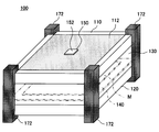
- a vibration isolator 170 is provided on the outer periphery of both the air supply unit 110 and the exhaust unit 120.
- the shape and mounting position of the vibration isolator 170 are not limited to this.
- the vibration isolator 172 having a shape extending from the air supply unit 110 to the exhaust unit 120 may be provided at four corners of the substrate storage apparatus 100.
- an outer container that can store the entire substrate storage apparatus 100 may be provided. According to this, for example, when the substrate storage device 100 is taken out of the clean room and transported by a truck or the like, the effect of preventing foreign matter adhesion of the mask blank M can be further enhanced. Specifically, for example, as shown in FIG. 8, an outer container 180 is provided so as to cover the substrate storage device 100.
- the vibration isolating effect when the entire outer container 180 is conveyed can be further enhanced.
- the vibration isolating material is not necessarily provided inside the outer container 180, and may be provided outside the outer container 180. Moreover, you may make it provide a vibration isolator in both the inner side and the outer side of the outer side container 180. FIG.
- vibration is detected by providing an anti-vibration sensor as the state sensor 154, it can be detected that large vibration has occurred.
- the vibration proof sensor may be monitored and it may be determined that the foreign matter of the mask blank M has adhered when a large vibration exceeding a predetermined threshold occurs.
- a circulation path 182 for returning the exhaust from the exhaust unit 120 to the air supply unit 110 may be formed between the substrate storage device 100 and the outer container 180.
- FIG. 8 is a specific example of the case where a vibration isolating material 172 as shown in FIG. 7 is provided between the substrate storage device 100 and the outer container 180 so that the circulation path 182 is provided between the vibration isolating materials 172.
- the effect of preventing foreign matter from adhering to the mask blanks M during conveyance of the outer container 180 can be enhanced.
- the foreign matter is removed by the air supply filter 112 by circulating through the circulation path 182, so that the inside of the outer container 180 can always be kept clean.
- an introduction port for introducing purge gas may be provided instead of taking outside air into the substrate storage apparatus 100.
- a purge gas such as dry air or nitrogen can be introduced from the introduction port.
- an introduction port 114 is provided in the air supply unit 110, and a purge gas supply source 116 is connected to the introduction port 114.
- the side wall 130 is airtightly provided between the air supply unit 110 and the exhaust unit 120 .
- the present invention is not limited to this.
- the side wall 130 may be detachably provided, or may be provided to be openable and closable. By providing the side wall 130 so that it can be opened and closed, the mask blanks M can be taken in and out from the side by a transfer arm (not shown).
- the side wall 130 may be provided on a part of the four side surfaces of the substrate storage apparatus 100, but is not necessarily provided.
- the side walls 130 may not be provided on all four side surfaces of the substrate storage device 100.
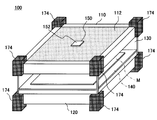
- the side surfaces may be opened such that the four corners of the air supply unit 110 and the exhaust unit 120 are supported by the support member 132. According to this, it becomes easy to take in and out the mask blanks M from the open side by a transfer arm or the like (not shown).
- the outside air enters not only from the air supply filter 112 but also from the opening on the side surface. In this case, a flow toward the exhaust unit 120 is always formed. Therefore, it is possible to prevent foreign matter from adhering to the mask blanks M.
- a mounting hole 150 similar to that shown in FIG. 1 is provided, and any one or two or more of the state sensor 154, the particle charging device 156, and the temperature control device 158 are provided. The combination can be provided detachably. Thereby, since an optimal function can be provided according to the use environment, even if foreign matter enters along with the outside air from the side surface, it is possible to effectively prevent foreign matter from adhering to the mask blank M.
- a vibration isolating material may be provided on the outside thereof.
- the vibration isolator 170 shown in FIG. 6 may be provided, or the vibration isolator 172 shown in FIG. 7 may be provided.
- a vibration isolator 174 may be provided at each of the four corners of the air supply unit 110 and the exhaust unit 120.
- an outer container that can store the entire substrate storage apparatus 100 may be provided. According to this, for example, when the substrate storage device 100 is taken out of the clean room and transported by a truck or the like, the effect of preventing foreign matter adhesion of the mask blank M can be further enhanced.
- an outer container 180 is provided so as to cover the substrate storage device 100.
- the vibration isolating effect when the entire outer container 180 is conveyed can be further enhanced.
- the outer container 180 is provided with a closing plate 184 that closes all the side openings when the substrate storage device 100 is stored, and the exhaust container 120 is provided between the substrate storage device 100 and the outer container 180.
- a circulation path 182 for returning the exhaust gas to the air supply unit 110 may be formed.
- a vibration isolator 174 as shown in FIG. 11 is provided between the substrate storage device 100 and the outer container 180, thereby forming a circulation path 182 between the anti-vibration members 174 on the outside of the closing plate 184. This is a specific example.
- the detachable configuration of the state sensor 154, the particle charging device 156, and the temperature control device 158 is not limited to the above embodiment.
- the present invention is not limited to this.
- the present invention may be applied to a substrate storage device for semiconductor wafers, FPD substrates, and photomasks.
- the present invention is applicable to a substrate storage device that stores and transports a substrate such as a mask blank.
- substrate storage device 110 air supply unit 112 air supply filter 114 introduction port 116 gas supply source 120 exhaust unit 122 fan 130 side wall 132 support member 140 substrate mounting plate 142 communication hole 150 mounting hole 152 mounting unit 154 state sensor 156 particle charging device 158 Temperature control device 160 Control unit 162 Storage unit 164 Operation unit 170,172,174 Antivibration material 180 Outer container 182 Circulation path 184 Blocking plate M Mask blanks
Landscapes
- Engineering & Computer Science (AREA)
- Mechanical Engineering (AREA)
- Physics & Mathematics (AREA)
- General Physics & Mathematics (AREA)
- Container, Conveyance, Adherence, Positioning, Of Wafer (AREA)
- Packaging Frangible Articles (AREA)
- Preparing Plates And Mask In Photomechanical Process (AREA)
- Packages (AREA)
Abstract
Description
先ず,本実施形態にかかる基板収納装置を図面を参照しながら説明する。ここでは,基板としてのマスクブランクスを1枚ずつ収納して搬送する基板収納装置を例に挙げる。図1は本実施形態にかかる基板収納装置の構成例を示す斜視図であり,図2は基板収納装置の縦断面図である。図1に示すように基板収納装置100の外観は箱状であり,その内部に1枚のマスクブランクスMを水平に収納できるように構成されている。
次に,上述した状態センサ,パーティクル帯電装置,温調装置を装着した基板収納装置100の具体例について説明する。例えば図1に示すように本実施形態にかかる基板収納装置100はその給気部110に装着孔150を設け,状態センサ,パーティクル帯電装置,温調装置に設けた装着部152をこの装着孔150に取り付けることによって着脱自在に装着できる。
110 給気部
112 給気フィルタ
114 導入ポート
116 ガス供給源
120 排気部
122 ファン
130 側壁
132 支持部材
140 基板載置板
142 連通孔
150 装着孔
152 装着部
154 状態センサ
156 パーティクル帯電装置
158 温調装置
160 制御部
162 記憶部
164 操作部
170,172,174 防振材
180 外側容器
182 循環路
184 閉塞板
M マスクブランクス
Claims (12)
- 基板を収納する基板収納装置であって,
前記基板収納装置内に外気を取り込む給気部と,
前記給気部に対向して配置された排気部と,
前記給気部と前記排気部との間に設けられ,これらの間を連通する連通孔を有する基板載置板と,
前記給気部に設けられた給気フィルタと,
前記給気部又は前記排気部に設けられたファンと,を備え,
前記基板収納装置内の状態を検出する状態センサと,パーティクル帯電装置と,温調装置とのいずれか又は2つ以上の組合せを着脱自在に設けたことを特徴とする基板収納装置。 - 前記状態センサは,温度センサ,帯電センサ,パーティクルセンサ,振動センサ,ガスセンサのいずれか又は2つ以上の組み合せであることを特徴とする請求項1に記載の基板収納装置。
- 前記状態センサの出力を記憶する記憶部と,
前記記憶部に記憶された前記状態センサの出力が所定の閾値を超えたか否かを判定する制御部と,
を設けたことを特徴とする請求項2に記載の基板収納装置。 - 前記基板収納装置を覆うように収納する外側容器を備え,
前記基板収納装置と前記外側容器との間に,前記排気部からの排気を前記給気部に戻す循環路を形成したことを特徴とする請求項1~3のいずれかに記載の基板収納装置。 - 前記基板収納装置と前記外側容器との間に防振材を設けて,前記防振材の間を前記循環路にしたことを特徴とする請求項4に記載の基板収納装置。
- 前記基板収納装置の外側又は前記外側容器の外側に防振材を設けたことを特徴とする請求項4に記載の基板収納装置。
- 前記給気部と前記排気部との間には,側板を着脱自在に設けたことを特徴とする請求項6に記載の基板収納容器。
- 基板を収納する基板収納装置であって,
前記基板収納装置内にパージガスを導入する導入ポートを設けた給気部と,
前記給気部に対向して配置された排気部と,
前記給気部と前記排気部との間に設けられ,これらの間を連通する連通孔を有する基板載置板と,
前記給気部又は前記排気部に設けられたファンと,を備え,
前記基板収納装置内の状態を検出する状態センサと,パーティクル帯電装置と,温調装置とのいずれか又は2つ以上の組合せを着脱自在に設けたことを特徴とする基板収納装置。 - 基板を収納する基板収納装置であって,
前記基板収納装置内に外気を取り込む給気部と,
前記給気部に対向して配置された排気部と,
前記給気部と前記排気部との間に設けられ,これらの間を連通する連通孔を有する基板載置板と,
前記給気部又は前記排気部に設けられたファンと,を備え,
前記基板収納装置内の状態を検出する状態センサと,パーティクル帯電装置と,温調装置とのいずれか又は2つ以上の組合せを着脱自在に設け,
前記排気部と前記給気部との間は開口していることを特徴とする基板収納装置。 - 前記基板収納装置を覆うように収納する外側容器を備え,
前記外側容器には,前記排気部と前記給気部との間は開口を閉塞する閉塞板を設け,
前記基板収納装置と前記外側容器との間に,前記排気部からの排気を前記給気部に戻す循環路を形成したことを特徴とする請求項9に記載の基板収納装置。 - 前記基板収納装置と前記外側容器との間に防振材を設けるとともに,前記防振材の間を前記循環路にしたことを特徴とする請求項10に記載の基板収納装置。
- 前記基板収納装置の外側又は前記外側容器の外側に防振材を設けたことを特徴とする請求項10に記載の基板収納装置。
Priority Applications (3)
| Application Number | Priority Date | Filing Date | Title |
|---|---|---|---|
| CN2011800065640A CN102714169A (zh) | 2010-03-04 | 2011-02-21 | 基板收纳装置 |
| KR1020127024269A KR101433068B1 (ko) | 2010-03-04 | 2011-02-21 | 기판 수납 장치 |
| US13/582,079 US20120325349A1 (en) | 2010-03-04 | 2011-02-21 | Substrate accommodation device |
Applications Claiming Priority (2)
| Application Number | Priority Date | Filing Date | Title |
|---|---|---|---|
| JP2010048380A JP5398595B2 (ja) | 2010-03-04 | 2010-03-04 | 基板収納装置 |
| JP2010-048380 | 2010-03-04 |
Publications (1)
| Publication Number | Publication Date |
|---|---|
| WO2011108215A1 true WO2011108215A1 (ja) | 2011-09-09 |
Family
ID=44541885
Family Applications (1)
| Application Number | Title | Priority Date | Filing Date |
|---|---|---|---|
| PCT/JP2011/000942 Ceased WO2011108215A1 (ja) | 2010-03-04 | 2011-02-21 | 基板収納装置 |
Country Status (5)
| Country | Link |
|---|---|
| US (1) | US20120325349A1 (ja) |
| JP (1) | JP5398595B2 (ja) |
| KR (1) | KR101433068B1 (ja) |
| CN (1) | CN102714169A (ja) |
| WO (1) | WO2011108215A1 (ja) |
Cited By (2)
| Publication number | Priority date | Publication date | Assignee | Title |
|---|---|---|---|---|
| CN103713468A (zh) * | 2013-12-24 | 2014-04-09 | 京东方科技集团股份有限公司 | 一种掩模板盒 |
| CN114326294A (zh) * | 2020-09-30 | 2022-04-12 | 家登精密工业股份有限公司 | 具有收容环境检测的基板收容装置 |
Families Citing this family (13)
| Publication number | Priority date | Publication date | Assignee | Title |
|---|---|---|---|---|
| JP2014157190A (ja) * | 2013-02-14 | 2014-08-28 | Toshiba Corp | 基板収納容器及び露光装置 |
| CN104973349A (zh) * | 2014-04-03 | 2015-10-14 | 四川虹视显示技术有限公司 | 玻璃基板储藏装置 |
| JP2016219620A (ja) * | 2015-05-21 | 2016-12-22 | ルネサスエレクトロニクス株式会社 | 半導体装置の製造方法およびそれに用いられるfoup |
| CN107615471B (zh) * | 2015-05-22 | 2021-09-28 | 未来儿股份有限公司 | 基板收纳容器 |
| JP2017157641A (ja) | 2016-02-29 | 2017-09-07 | キヤノン株式会社 | インプリント装置、インプリント方法、および物品の製造方法 |
| US9911634B2 (en) | 2016-06-27 | 2018-03-06 | Globalfoundries Inc. | Self-contained metrology wafer carrier systems |
| JP6855774B2 (ja) * | 2016-12-13 | 2021-04-07 | Tdk株式会社 | ウエハ搬送容器内雰囲気計測装置、ウエハ搬送容器、ウエハ搬送容器内清浄化装置及びウエハ搬送容器内清浄化方法 |
| JP2019192683A (ja) * | 2018-04-19 | 2019-10-31 | 株式会社ディスコ | 搬送機構 |
| KR102172073B1 (ko) * | 2018-09-28 | 2020-10-30 | 세메스 주식회사 | 기판 수납 장치 및 상기 기판 수납 장치를 이용한 기판 처리 장치 |
| JP7261000B2 (ja) * | 2018-12-03 | 2023-04-19 | キヤノン株式会社 | 容器、処理装置、異物除去方法、および物品の製造方法 |
| KR20210014824A (ko) | 2019-07-30 | 2021-02-10 | 삼성전자주식회사 | 마스크 저장 장치 |
| KR102242026B1 (ko) * | 2020-06-29 | 2021-04-19 | 피엠씨글로벌 주식회사 | 내부공간에 질소가스가 주입되는 포토마스크 케이스 |
| US12272573B2 (en) * | 2021-03-11 | 2025-04-08 | Taiwan Semiconductor Manufacturing Company, Ltd. | Load port and methods of operation |
Citations (11)
| Publication number | Priority date | Publication date | Assignee | Title |
|---|---|---|---|---|
| JPS55134239A (en) * | 1979-04-04 | 1980-10-18 | Toshiba Corp | Clean box |
| JPS63503259A (ja) * | 1985-12-23 | 1988-11-24 | アシスト テクノロジーズ インコーポレーテッド | 処理しようとする物品を収容する持ち運びできる容器 |
| JPS6411945U (ja) * | 1987-07-10 | 1989-01-23 | ||
| JPH047855A (ja) * | 1990-04-25 | 1992-01-13 | Hitachi Ltd | ウエハキヤリア |
| JP2001053136A (ja) * | 1999-08-06 | 2001-02-23 | Dainippon Printing Co Ltd | ケース |
| JP2001330620A (ja) * | 2000-03-14 | 2001-11-30 | Omron Corp | 振動・衝撃警報装置 |
| JP2002122382A (ja) * | 2000-01-28 | 2002-04-26 | Ebara Corp | 基板容器 |
| JP2002176097A (ja) * | 2000-12-05 | 2002-06-21 | Ebara Corp | 基板搬送容器およびその使用方法 |
| JP2004047929A (ja) * | 2002-05-13 | 2004-02-12 | Fujitsu Ltd | 分子汚染監視システム、保管搬送容器および分子汚染センサ |
| JP2005274181A (ja) * | 2004-03-23 | 2005-10-06 | Ebara Corp | 環境ボックス内のケミカルガスフィルタの消耗度測定方法及び湿度測定方法 |
| JP2005324913A (ja) * | 2004-05-13 | 2005-11-24 | Kyokuhei Glass Kako Kk | ガラス基板搬送用ボックスに用いる空気清浄具及びその使用方法 |
Family Cites Families (13)
| Publication number | Priority date | Publication date | Assignee | Title |
|---|---|---|---|---|
| JPS61160934A (ja) * | 1985-01-10 | 1986-07-21 | Canon Inc | 投影光学装置 |
| US5143552A (en) * | 1988-03-09 | 1992-09-01 | Tokyo Electron Limited | Coating equipment |
| US5064337A (en) * | 1988-07-19 | 1991-11-12 | Tokyo Electron Limited | Handling apparatus for transferring carriers and a method of transferring carriers |
| DE69228014T2 (de) * | 1991-01-29 | 1999-05-27 | Shinko Electric Co., Ltd., Tokio/Tokyo | Einheit zum luftdichten Aufbewahren von Halbleiterscheiben |
| JP2001092114A (ja) * | 2000-07-17 | 2001-04-06 | Yuukou Jushi Kk | フォトマスク等基板の収納ケース |
| KR100745867B1 (ko) * | 2000-08-23 | 2007-08-02 | 동경 엘렉트론 주식회사 | 수직열처리장치 및 피처리체를 운송하는 방법 |
| TW200520049A (en) * | 2003-10-21 | 2005-06-16 | Nikon Corp | Environment-controlling apparatus, device-producing apparatus, device-producing method, and exposure apparatus |
| JP2005167083A (ja) * | 2003-12-04 | 2005-06-23 | Daifuku Co Ltd | ガラス基板用の搬送設備 |
| US7224432B2 (en) * | 2004-05-14 | 2007-05-29 | Canon Kabushiki Kaisha | Stage device, exposure apparatus, and device manufacturing method |
| US8272827B2 (en) * | 2005-11-07 | 2012-09-25 | Bufano Michael L | Reduced capacity carrier, transport, load port, buffer system |
| JP4765607B2 (ja) * | 2005-12-19 | 2011-09-07 | 大日本印刷株式会社 | 耐衝撃性クリーン容器、試料移載システム |
| JP4756372B2 (ja) * | 2006-09-13 | 2011-08-24 | 株式会社ダイフク | 基板処理方法 |
| JP5171524B2 (ja) * | 2007-10-04 | 2013-03-27 | 株式会社日立ハイテクノロジーズ | 物体表面の欠陥検査装置および方法 |
-
2010
- 2010-03-04 JP JP2010048380A patent/JP5398595B2/ja not_active Expired - Fee Related
-
2011
- 2011-02-21 WO PCT/JP2011/000942 patent/WO2011108215A1/ja not_active Ceased
- 2011-02-21 CN CN2011800065640A patent/CN102714169A/zh active Pending
- 2011-02-21 US US13/582,079 patent/US20120325349A1/en not_active Abandoned
- 2011-02-21 KR KR1020127024269A patent/KR101433068B1/ko not_active Expired - Fee Related
Patent Citations (11)
| Publication number | Priority date | Publication date | Assignee | Title |
|---|---|---|---|---|
| JPS55134239A (en) * | 1979-04-04 | 1980-10-18 | Toshiba Corp | Clean box |
| JPS63503259A (ja) * | 1985-12-23 | 1988-11-24 | アシスト テクノロジーズ インコーポレーテッド | 処理しようとする物品を収容する持ち運びできる容器 |
| JPS6411945U (ja) * | 1987-07-10 | 1989-01-23 | ||
| JPH047855A (ja) * | 1990-04-25 | 1992-01-13 | Hitachi Ltd | ウエハキヤリア |
| JP2001053136A (ja) * | 1999-08-06 | 2001-02-23 | Dainippon Printing Co Ltd | ケース |
| JP2002122382A (ja) * | 2000-01-28 | 2002-04-26 | Ebara Corp | 基板容器 |
| JP2001330620A (ja) * | 2000-03-14 | 2001-11-30 | Omron Corp | 振動・衝撃警報装置 |
| JP2002176097A (ja) * | 2000-12-05 | 2002-06-21 | Ebara Corp | 基板搬送容器およびその使用方法 |
| JP2004047929A (ja) * | 2002-05-13 | 2004-02-12 | Fujitsu Ltd | 分子汚染監視システム、保管搬送容器および分子汚染センサ |
| JP2005274181A (ja) * | 2004-03-23 | 2005-10-06 | Ebara Corp | 環境ボックス内のケミカルガスフィルタの消耗度測定方法及び湿度測定方法 |
| JP2005324913A (ja) * | 2004-05-13 | 2005-11-24 | Kyokuhei Glass Kako Kk | ガラス基板搬送用ボックスに用いる空気清浄具及びその使用方法 |
Cited By (3)
| Publication number | Priority date | Publication date | Assignee | Title |
|---|---|---|---|---|
| CN103713468A (zh) * | 2013-12-24 | 2014-04-09 | 京东方科技集团股份有限公司 | 一种掩模板盒 |
| CN114326294A (zh) * | 2020-09-30 | 2022-04-12 | 家登精密工业股份有限公司 | 具有收容环境检测的基板收容装置 |
| TWI798778B (zh) * | 2020-09-30 | 2023-04-11 | 家登精密工業股份有限公司 | 具有收容環境偵測之基板收容裝置、偵測裝置及安裝偵測裝置至基板收容裝置的方法 |
Also Published As
| Publication number | Publication date |
|---|---|
| US20120325349A1 (en) | 2012-12-27 |
| JP2011186006A (ja) | 2011-09-22 |
| CN102714169A (zh) | 2012-10-03 |
| JP5398595B2 (ja) | 2014-01-29 |
| KR101433068B1 (ko) | 2014-08-22 |
| KR20130007577A (ko) | 2013-01-18 |
Similar Documents
| Publication | Publication Date | Title |
|---|---|---|
| JP5398595B2 (ja) | 基板収納装置 | |
| TWI780030B (zh) | 形成用於一半導體基板並具有低溼度值的一乾淨的環境的方法及系統 | |
| JP3425592B2 (ja) | 処理装置 | |
| JP4685584B2 (ja) | 塗布、現像装置 | |
| JP4354675B2 (ja) | 薄板状電子部品クリーン移載装置および薄板状電子製品製造システム | |
| CN102810461B (zh) | 基板处理设备和基板处理方法 | |
| CN103094164B (zh) | 基板处理系统和基板搬送方法 | |
| KR101295791B1 (ko) | 기판 처리 설비 및 기판 처리 방법 | |
| CN107039322A (zh) | 微环境装置 | |
| JP2009164369A (ja) | 被収容物搬送システム | |
| JP5002471B2 (ja) | 基板洗浄装置、基板洗浄方法、プログラム及びコンピュータ記憶媒体 | |
| US20100236405A1 (en) | Substrate transfer device and substrate transfer method | |
| JP2015146348A (ja) | Efemシステム | |
| JP2006005072A (ja) | 基板搬送保管容器及びその使用方法 | |
| CN114944350A (zh) | 用于微影罩幕检查的方法及系统 | |
| US7477353B2 (en) | Lithography apparatus, method of forming pattern and method of manufacturing semiconductor device | |
| JP2002083854A (ja) | 基板搬送装置 | |
| JP7316102B2 (ja) | ウエハ搬送装置 | |
| TW471008B (en) | Substrate transport device | |
| CN110313060B (zh) | 基板处理系统 | |
| JP4320158B2 (ja) | 局所クリーン化搬送室および局所クリーン化処理装置 | |
| JP4872448B2 (ja) | 塗布、現像装置、塗布、現像方法及び記憶媒体。 | |
| JP6036742B2 (ja) | 集塵用治具、基板処理装置及びパーティクル捕集方法。 | |
| KR101895932B1 (ko) | 포토 마스크 세정 설비의 냉각장치 | |
| JP4044203B2 (ja) | 基板処理装置 |
Legal Events
| Date | Code | Title | Description |
|---|---|---|---|
| WWE | Wipo information: entry into national phase |
Ref document number: 201180006564.0 Country of ref document: CN |
|
| 121 | Ep: the epo has been informed by wipo that ep was designated in this application |
Ref document number: 11750329 Country of ref document: EP Kind code of ref document: A1 |
|
| WWE | Wipo information: entry into national phase |
Ref document number: 13582079 Country of ref document: US |
|
| NENP | Non-entry into the national phase |
Ref country code: DE |
|
| ENP | Entry into the national phase |
Ref document number: 20127024269 Country of ref document: KR Kind code of ref document: A |
|
| 122 | Ep: pct application non-entry in european phase |
Ref document number: 11750329 Country of ref document: EP Kind code of ref document: A1 |