WO2011070703A1 - シリカ容器及びその製造方法 - Google Patents
シリカ容器及びその製造方法 Download PDFInfo
- Publication number
- WO2011070703A1 WO2011070703A1 PCT/JP2010/006179 JP2010006179W WO2011070703A1 WO 2011070703 A1 WO2011070703 A1 WO 2011070703A1 JP 2010006179 W JP2010006179 W JP 2010006179W WO 2011070703 A1 WO2011070703 A1 WO 2011070703A1
- Authority
- WO
- WIPO (PCT)
- Prior art keywords
- silica
- inner layer
- substrate
- raw material
- forming
- Prior art date
Links
Images


Classifications
-
- B—PERFORMING OPERATIONS; TRANSPORTING
- B65—CONVEYING; PACKING; STORING; HANDLING THIN OR FILAMENTARY MATERIAL
- B65D—CONTAINERS FOR STORAGE OR TRANSPORT OF ARTICLES OR MATERIALS, e.g. BAGS, BARRELS, BOTTLES, BOXES, CANS, CARTONS, CRATES, DRUMS, JARS, TANKS, HOPPERS, FORWARDING CONTAINERS; ACCESSORIES, CLOSURES, OR FITTINGS THEREFOR; PACKAGING ELEMENTS; PACKAGES
- B65D13/00—Containers having bodies formed by interconnecting two or more rigid, or substantially rigid, components made wholly or mainly of the same material, other than metal, plastics, wood, or substitutes therefor
- B65D13/02—Containers having bodies formed by interconnecting two or more rigid, or substantially rigid, components made wholly or mainly of the same material, other than metal, plastics, wood, or substitutes therefor of glass, pottery, or other ceramic material
-
- C—CHEMISTRY; METALLURGY
- C03—GLASS; MINERAL OR SLAG WOOL
- C03B—MANUFACTURE, SHAPING, OR SUPPLEMENTARY PROCESSES
- C03B19/00—Other methods of shaping glass
- C03B19/09—Other methods of shaping glass by fusing powdered glass in a shaping mould
- C03B19/095—Other methods of shaping glass by fusing powdered glass in a shaping mould by centrifuging, e.g. arc discharge in rotating mould
-
- C—CHEMISTRY; METALLURGY
- C30—CRYSTAL GROWTH
- C30B—SINGLE-CRYSTAL GROWTH; UNIDIRECTIONAL SOLIDIFICATION OF EUTECTIC MATERIAL OR UNIDIRECTIONAL DEMIXING OF EUTECTOID MATERIAL; REFINING BY ZONE-MELTING OF MATERIAL; PRODUCTION OF A HOMOGENEOUS POLYCRYSTALLINE MATERIAL WITH DEFINED STRUCTURE; SINGLE CRYSTALS OR HOMOGENEOUS POLYCRYSTALLINE MATERIAL WITH DEFINED STRUCTURE; AFTER-TREATMENT OF SINGLE CRYSTALS OR A HOMOGENEOUS POLYCRYSTALLINE MATERIAL WITH DEFINED STRUCTURE; APPARATUS THEREFOR
- C30B15/00—Single-crystal growth by pulling from a melt, e.g. Czochralski method
- C30B15/10—Crucibles or containers for supporting the melt
-
- C—CHEMISTRY; METALLURGY
- C03—GLASS; MINERAL OR SLAG WOOL
- C03B—MANUFACTURE, SHAPING, OR SUPPLEMENTARY PROCESSES
- C03B20/00—Processes specially adapted for the production of quartz or fused silica articles, not otherwise provided for
-
- C—CHEMISTRY; METALLURGY
- C03—GLASS; MINERAL OR SLAG WOOL
- C03C—CHEMICAL COMPOSITION OF GLASSES, GLAZES OR VITREOUS ENAMELS; SURFACE TREATMENT OF GLASS; SURFACE TREATMENT OF FIBRES OR FILAMENTS MADE FROM GLASS, MINERALS OR SLAGS; JOINING GLASS TO GLASS OR OTHER MATERIALS
- C03C3/00—Glass compositions
- C03C3/04—Glass compositions containing silica
- C03C3/06—Glass compositions containing silica with more than 90% silica by weight, e.g. quartz
-
- C—CHEMISTRY; METALLURGY
- C30—CRYSTAL GROWTH
- C30B—SINGLE-CRYSTAL GROWTH; UNIDIRECTIONAL SOLIDIFICATION OF EUTECTIC MATERIAL OR UNIDIRECTIONAL DEMIXING OF EUTECTOID MATERIAL; REFINING BY ZONE-MELTING OF MATERIAL; PRODUCTION OF A HOMOGENEOUS POLYCRYSTALLINE MATERIAL WITH DEFINED STRUCTURE; SINGLE CRYSTALS OR HOMOGENEOUS POLYCRYSTALLINE MATERIAL WITH DEFINED STRUCTURE; AFTER-TREATMENT OF SINGLE CRYSTALS OR A HOMOGENEOUS POLYCRYSTALLINE MATERIAL WITH DEFINED STRUCTURE; APPARATUS THEREFOR
- C30B29/00—Single crystals or homogeneous polycrystalline material with defined structure characterised by the material or by their shape
- C30B29/02—Elements
- C30B29/06—Silicon
-
- C—CHEMISTRY; METALLURGY
- C30—CRYSTAL GROWTH
- C30B—SINGLE-CRYSTAL GROWTH; UNIDIRECTIONAL SOLIDIFICATION OF EUTECTIC MATERIAL OR UNIDIRECTIONAL DEMIXING OF EUTECTOID MATERIAL; REFINING BY ZONE-MELTING OF MATERIAL; PRODUCTION OF A HOMOGENEOUS POLYCRYSTALLINE MATERIAL WITH DEFINED STRUCTURE; SINGLE CRYSTALS OR HOMOGENEOUS POLYCRYSTALLINE MATERIAL WITH DEFINED STRUCTURE; AFTER-TREATMENT OF SINGLE CRYSTALS OR A HOMOGENEOUS POLYCRYSTALLINE MATERIAL WITH DEFINED STRUCTURE; APPARATUS THEREFOR
- C30B35/00—Apparatus not otherwise provided for, specially adapted for the growth, production or after-treatment of single crystals or of a homogeneous polycrystalline material with defined structure
- C30B35/002—Crucibles or containers
-
- C—CHEMISTRY; METALLURGY
- C03—GLASS; MINERAL OR SLAG WOOL
- C03B—MANUFACTURE, SHAPING, OR SUPPLEMENTARY PROCESSES
- C03B2201/00—Type of glass produced
- C03B2201/06—Doped silica-based glasses
- C03B2201/30—Doped silica-based glasses doped with metals, e.g. Ga, Sn, Sb, Pb or Bi
- C03B2201/54—Doped silica-based glasses doped with metals, e.g. Ga, Sn, Sb, Pb or Bi doped with beryllium, magnesium or alkaline earth metals
-
- C—CHEMISTRY; METALLURGY
- C03—GLASS; MINERAL OR SLAG WOOL
- C03C—CHEMICAL COMPOSITION OF GLASSES, GLAZES OR VITREOUS ENAMELS; SURFACE TREATMENT OF GLASS; SURFACE TREATMENT OF FIBRES OR FILAMENTS MADE FROM GLASS, MINERALS OR SLAGS; JOINING GLASS TO GLASS OR OTHER MATERIALS
- C03C2201/00—Glass compositions
- C03C2201/06—Doped silica-based glasses
- C03C2201/30—Doped silica-based glasses containing metals
- C03C2201/54—Doped silica-based glasses containing metals containing beryllium, magnesium or alkaline earth metals
-
- Y—GENERAL TAGGING OF NEW TECHNOLOGICAL DEVELOPMENTS; GENERAL TAGGING OF CROSS-SECTIONAL TECHNOLOGIES SPANNING OVER SEVERAL SECTIONS OF THE IPC; TECHNICAL SUBJECTS COVERED BY FORMER USPC CROSS-REFERENCE ART COLLECTIONS [XRACs] AND DIGESTS
- Y02—TECHNOLOGIES OR APPLICATIONS FOR MITIGATION OR ADAPTATION AGAINST CLIMATE CHANGE
- Y02P—CLIMATE CHANGE MITIGATION TECHNOLOGIES IN THE PRODUCTION OR PROCESSING OF GOODS
- Y02P40/00—Technologies relating to the processing of minerals
- Y02P40/50—Glass production, e.g. reusing waste heat during processing or shaping
- Y02P40/57—Improving the yield, e-g- reduction of reject rates
Definitions
- the present invention relates to a silica container having silica as a main constituent and a method for producing the same, and more particularly to a low-cost, high dimensional accuracy, high heat-resistant silica container and a method for producing the same.
- Silica glass is a lens for projection exposure equipment (lithography equipment) for manufacturing large-scale integrated circuits (LSIs), prisms, photomasks and TFT substrates for displays, lamp tubes, window materials, reflectors, semiconductor industry cleaning containers, silicon Used as a semiconductor melting container.
- these silica glass raw materials must use expensive compounds such as silicon tetrachloride, and the silica glass melting temperature and processing temperature are about 2000 ° C., which is extremely high, resulting in high energy consumption and high cost. It was expensive. Therefore, conventionally, a method for producing silica glass using a relatively inexpensive powder raw material has been considered.
- Patent Document 1 at least two different silica glass particles, for example, silica glass fine powder and silica glass particles are mixed to form a water-containing suspension, then pressure-molded, and sintered at high temperature to contain silica.
- a method of obtaining a composite is shown.
- opaque silica is produced by preparing a mixed liquid (slurry) containing silica glass particles having a size of 100 ⁇ m or less and silica glass granules having a size of 100 ⁇ m or more, injecting the mixture into a mold, and then drying and sintering.
- a method of making a glass composite is shown.
- these conventional slip casting methods have a large shrinkage of the molded body in the drying process and the sintering process, and it has not been possible to produce a thick silica glass molded body with high dimensional accuracy.
- each of the methods for producing a silica glass molded body has problems. Therefore, even now, as a method for producing a silica crucible for producing single crystal silicon for LSI (for devices), the production methods described in Patent Document 3 and Patent Document 4 are used. In these methods, quartz powder or synthetic cristobalite powder treated with ultra-high purity is put into a rotating mold, and after molding, a carbon electrode is pushed in from the top and an electric discharge is applied to the carbon electrode to cause arc discharge. This is a method in which the quartz raw material powder is melted and sintered by raising the atmospheric temperature to the melting temperature range of quartz powder (estimated to be about 1800 to 2100 ° C.).
- Patent Document 5 discloses a method for improving the silicon melt etching resistance of a silica crucible for pulling a single crystal.
- Patent Document 5 shows the effect of applying a crystallization accelerator to the inner surface of a silica glass crucible.
- the crystallization accelerator alkaline earth metal elements Mg, Sr, Ca, Ba which are group 2a elements and Al of group 3b elements are shown.
- the silica glass crucible as shown in Patent Document 5 is not a bubble-free transparent silica glass layer having a complete inner surface portion of the crucible, but contains non-uniformly melted particles and minute bubbles of various dope elements. It was something to do.
- the pulled silicon single crystal often contains defects such as silica fine particles, voids, and pinholes as foreign matters. Further, there has been a problem that the fine bubbles existing inside the crucible are greatly expanded during the pulling of the silicon single crystal and the inner surface of the crucible is deformed.
- Patent Document 6 discloses a method of reducing bubbles in silica glass at the inner surface portion of a silica crucible for pulling up a single crystal and suppressing bubble expansion of the silica crucible in use.
- the silica crucible inner surface with less bubbles can be created by adding a hydrogen molecule concentration of 5 ⁇ 10 17 to 3 ⁇ 10 19 (molecules / cm 3 ) in the silica crucible raw material powder. ing.
- this method can reduce the bubble content on the inner surface of the silica crucible, the silicon melt etching resistance cannot be improved by crystallizing the inner surface of the silica crucible into cristobalite.
- hydrogen molecules doped in the raw material powder are gradually released to the outside during storage of the raw material powder, and there is a problem that the raw material powder containing hydrogen cannot be stored for a long time.
- Patent Document 7 discloses a method for reducing bubble growth when using a silica crucible for pulling silicon.
- a method of degassing from the outside while making the inside of the container molded body a hydrogen or helium gas atmosphere during arc discharge melting with a carbon electrode in crucible production is shown.
- this method can reduce the bubble content in the inner surface of the silica glass, but can reduce the OH group concentration contained in the silica crucible to a constant value, or when the silica crucible is used, the inner surface is finely cristobalite. The durability and heat resistance of the crucible could not be improved by crystallization.
- Patent Document 8 discloses a method for reducing the bubble content of a silica crucible for pulling up a silicon single crystal. In this, it is shown that hydrogen or / and helium gas is supplied to the powder compact of the container at the time of heating the crucible.
- helium gas or argon gas is supplied to the powder compact of the container at the time of heating in crucible manufacture, and then helium gas or argon gas is started and continued while arc melting is started and continued.
- the supply of hydrogen gas is stopped or the supply amount is reduced, and the supply of hydrogen gas is started.
- JP 2002-362932 A JP 2004-131380 A Japanese Patent Publication No.4-222861 Japanese Patent Publication No. 7-29871 JP-A-8-2932 JP 2007-326780 A JP-A-8-268727 Japanese Patent Laid-Open No. 9-20586 JP 2000-344536 A
- the present invention has been made in view of the problems as described above, and has a high dimensional accuracy and high heat resistance, and a silica container production method capable of producing a silica container mainly composed of silica at low cost, and An object is to provide such a silica container.
- the present invention has been made in order to solve the above-mentioned problems, and is formed on a substrate having rotational symmetry, silica as a main component, and containing bubbles at least in the outer peripheral portion, and the inner surface of the substrate.
- a method for producing a silica container comprising an inner layer made of transparent silica glass, wherein at least a raw material powder for forming the substrate has a particle size of 10 to 1000 ⁇ m and contains Li, Na, and K contained therein. The total concentration is 50 wt.
- the particle diameter is 10 to 1000 ⁇ m, and a total of at least one of Ca, Sr, and Ba is 50 to 2000 wt.
- a step of producing ppm-containing silica powder a step of charging the base material forming raw material powder into a mold, and temporarily forming the powder into a predetermined shape while rotating the mold to form a temporary molded body of the base; Introducing the inner layer forming raw material powder on the inner surface of the substrate temporary molded body, and forming the inner layer temporary molded body into a predetermined shape corresponding to the inner surface of the substrate temporary molded body, Hydrogen or helium or a mixed gas thereof at 10 vol.
- the outer peripheral portion of the base temporary molded body is a sintered body,
- a method for producing a silica container comprising a step of forming an inner peripheral portion of a temporary molded body of the base body and a temporary molded body of the inner layer as a molten glass body and forming the base body and the inner layer.
- the present invention also includes a substrate having rotational symmetry, having silica as a main component and containing bubbles in at least an outer peripheral portion, and an inner layer made of transparent silica glass formed on the inner surface of the substrate.
- a method for producing a silica container wherein at least a raw material powder for forming the substrate has a particle size of 10 to 1000 ⁇ m and a total concentration of Li, Na, and K contained is 50 wt.
- the particle diameter is 10 to 1000 ⁇ m, and a total of at least one of Ca, Sr, and Ba is 50 to 2000 wt.
- a step of producing ppm-containing silica powder a step of charging the base material forming raw material powder into a mold, and temporarily forming the powder into a predetermined shape while rotating the mold to form a temporary molded body of the base;
- the outer peripheral portion of the base temporary molded body is made a sintered body, and the inner peripheral portion of the base temporary molded body is a molten glass body.
- a step of forming the inner layer on the inner surface of the base body by heating at a high temperature from the inside by a discharge heating melting method in a gas atmosphere containing a ratio exceeding%.
- At least one of the steps by the discharge heating melting method can be performed while reducing the pressure from the outside of the substrate or the temporary molded body of the substrate through the mold.
- at least one of the steps by the discharge heating melting method can be performed while reducing the pressure from the outside of the substrate or the temporary molded body of the substrate through the mold. The dissolved gas in the manufactured silica container can be reduced more effectively.
- the inner layer forming raw material powder is made from 100 to 1000 wt. It is contained at a concentration of ppm, and Al is 10 to 100 wt. It is preferable to contain at a concentration of ppm. In this way, the inner layer forming raw material powder is made from 100 to 1000 wt. It is contained at a concentration of ppm, and Al is 10 to 100 wt. If it is contained at a concentration of ppm, the inner layer can be a silica glass layer having higher light transmittance and extremely few bubbles.
- the gas atmosphere containing hydrogen or helium or a mixed gas thereof is preferably set to a dew point temperature of 15 ° C. to ⁇ 15 ° C. and controlled within a range of ⁇ 2 ° C. of the set dew point temperature. If the dew point temperature of the gas atmosphere is set and controlled in this way, the OH group content and moisture (H 2 O) content in the silica container can be reduced to predetermined values while being low in cost. .
- the gas atmosphere containing hydrogen or helium or a mixed gas thereof has a content ratio of hydrogen or helium or a mixed gas thereof of 100 vol. % Is preferable.
- the content ratio of hydrogen, helium or a mixed gas thereof in the gas atmosphere is set to 100 vol. If it is set to%, generation
- the present invention has a rotational symmetry, has silica as a main component, contains bubbles in the outer peripheral portion, and includes a transparent silica glass in the inner peripheral portion, and is formed on the inner surface of the substrate.
- a silica container comprising an inner layer made of transparent silica glass, wherein the substrate has a total concentration of Li, Na, and K of 50 wt.
- the linear transmittance at a light wavelength of 600 nm of a 10 mm thick double-sided parallel optical polishing sample cut out from the transparent silica glass of the inner peripheral portion of the substrate is 91.8 to 93.2%, and the inner layer is , Li, Na, K total concentration is 100 wt.
- the 10 mm-thick double-sided parallel optical polishing sample cut from the inner layer has a linear transmittance of 91.8 to 93.2% at a light wavelength of 600 nm, and the sample cut from the inner layer is vacuum
- a silica container characterized in that the amount of water molecules released when heated to 1000 ° C. is less than 2 ⁇ 10 17 molecules / g.
- the container inner wall is provided with a high impurity diffusion preventing effect and durability, etc. when used at a high temperature. And generation of bubbles on the inner wall of the container can be effectively suppressed. As a result, it is possible to suppress the adverse effect of the bubbles generated on the inner wall of the silica container on the contents.
- the light transmittance value reflects the amount of bubbles in the glass and the uniform solubility of the doping element.
- the inner layer has Ba of 100 to 1000 wt. It is contained at a concentration of ppm, and Al is 10 to 100 wt. It is preferable to contain it at a concentration of ppm.
- the inner layer has a Ba content of 100 to 1000 wt. It is contained at a concentration of ppm, and Al is 10 to 100 wt. If it is contained at a concentration of ppm, the inner layer can be a silica glass layer having higher light transmittance and extremely few bubbles.
- the inner layer contains OH groups in an amount of 1 to 50 wt. ppm, each concentration of Li, Na, K is 20 wt. ppb or less, and each concentration of Ti, Cr, Mn, Fe, Ni, Cu, Zn, Zr, Mo, and W is 10 wt. It is preferably ppb or less. If the OH group concentration and the concentration of each metal contained in the inner layer are such concentrations, it is possible to more effectively reduce the contamination of impurities contained in the manufactured silica container.
- the method for producing a silica container according to the present invention a high impurity diffusion preventing effect and durability are obtained when the produced silica container is used at a high temperature, and the generation of bubbles on the inner wall of the silica container is effective. Can be suppressed.
- the silica container according to the present invention is a low-cost silica container having sufficient temperature uniformity, it has a high impurity diffusion preventing effect and durability on the inner wall of the container when used at a high temperature.
- the generation of bubbles on the inner wall of the container can be effectively suppressed. As a result, it is possible to suppress the adverse effect of the bubbles generated on the inner wall of the silica container on the contents.
- the production of the conventional silica container has problems in terms of dimensional accuracy and cost.
- a silica container manufactured by a conventional method for manufacturing a silica container for example, the incorporation of bubbles into a silicon single crystal in a silica crucible for growing a silicon single crystal, the discharge of bubbles into the contents There were problems such as adverse effects.
- the present inventors have studied in view of such problems, and have found the following problems.
- a silica container such as a crucible or boat for metal silicon melting and silicon single crystal or polycrystal production
- heat uniformity inside the container in a heated high temperature atmosphere is required.
- at least the silica container has a double structure, the outer side of the container is porous white opaque silica, and the inner side of the container is a thick colorless transparent silica glass substantially free of bubbles. .
- a second problem is to provide an action (impurity shielding action) for preventing diffusion of impurities. This is to suppress the adverse effect of contamination on the contents accommodated in the silica container due to the impurities contained in the silica container.
- impurity shielding action for preventing diffusion of impurities.
- impurity metal elements contained in a silica container at the time of production of silicon crystals such as alkali metal elements Li, Na, K, but particularly Ti, Cr, Mn, Fe, Ni, Cu, Zn, Zr, Mo, When W or the like is taken into the silicon crystal, the photoelectric conversion efficiency is lowered particularly in a silicon device for solar.
- the inner surface of the silica container is finely crystallized (glass ceramic) so that the impurities contained in the silica container do not diffuse into the silicon melt, thereby preventing the impurity from diffusing. Further, the quality of the fine crystallized portion on the inner surface of the silica container is such that each crystal size is fine and dense, so that the crystallized layer of fine cristobalite or the like is used.
- the third problem is to impart etching resistance by finely crystallizing the inner surface of the silica container with fine cristobalite or the like.
- the component (SiO 2 ) itself of the silica container is dissolved in the silicon melt, so that if oxygen element is taken into the silicon crystal, for example, in a silicon device for solar power, the photoelectric conversion efficiency is lowered. End up. Therefore, the inner surface of the silica container has the characteristic that it is difficult to dissolve in the silicon melt (having silicon melt etching resistance), that is, the inner surface of the container is similarly finely crystallized with fine cristobalite, etc.
- At least one of alkaline earth metal elements Ca, Sr, Ba as a crystallization accelerator is heterogeneously doped in the inner surface layer of the silica container, and the inner surface layer contains fine bubbles.
- the silicon crystal is produced, the contained gas is released from the bubbles, and these released gases are eluted into the silicon melt, so that the gas bubbles are taken into the silicon crystal and cause structural defects called pinholes and voids. . Therefore, it should be a thick silica glass layer that does not contain bubbles in the inner surface layer part of the silica container, is completely colorless and transparent as silica glass, and the alkali earth metal element is uniformly dissolved, and has high light transmittance. Is the fourth problem.
- the present invention solves the above four technical problems simultaneously at a lower cost than a silica container such as a conventional high-purity single crystal silicon pulling crucible using a high-purity silica raw material powder. It is necessary to solve this, and this is the fifth problem.
- silica container solar grade crucible
- metal silicon melting container used as a material for solar cells (solar power generation, solar power generation)
- the present invention is not limited to this, and can be widely applied to all silica containers used at high temperatures with silica as a main component.
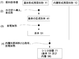
- FIG. 4 shows a schematic cross-sectional view of an example of a silica container according to the present invention.
- the silica container 71 according to the present invention has rotational symmetry, and the basic structure thereof includes a base 51 and an inner layer 56.
- the substrate 51 has rotational symmetry and has silica as a main component.
- substrate 51 contains a bubble in the outer peripheral part 51a of a base
- the inner peripheral portion 51b of the base includes transparent silica glass.
- the inner layer 56 is formed on the inner surface of the base 51 and is made of transparent silica glass.
- the total concentration of Li, Na, and K in the substrate 51 is 50 wt. ppm or less.
- the inner layer 56 contains at least one of Ca, Sr, and Ba at a total concentration of 50 to 2000 wt.
- the linear transmittance of a 10 mm-thick double-sided parallel optical polishing sample at a light wavelength of 600 nm is 91.8 to 93.2%, more preferably 92.4 to 93.2%. It is.
- the amount of water molecules released when the sample cut out from the inner layer 56 is heated to 1000 ° C. under vacuum is less than 2 ⁇ 10 17 molecules / g, preferably less than 1 ⁇ 10 17 molecules / g.
- the linear transmittance at a light wavelength of 600 nm of the double-sided parallel optical polishing sample having a thickness of 10 mm cut out from the inner peripheral portion 51b of the substrate 51 is 91.8 to 93.2%.
- silica container of the present invention may further include other layers as long as it has at least the base 51 and the inner layer 56.
- the silica container 71 configured in this manner has sufficient temperature uniformity at low cost. That is, among the silica containers, at least the outer peripheral side 51a of the substrate is made of a porous opaque silica body, and at least the inner layer 56 is made of a thick transparent silica glass body substantially free of bubbles, thereby increasing the silica container 71. When used under temperature, the uniformity of the temperature inside the silica container 71 can be enhanced.
- the silica container 71 when used at a high temperature of 1400 to 1600 ° C. by containing at least one of Ca, Sr and Ba, particularly Ba, in the inner layer 56 as described above, the surface of the silica glass The portion can be recrystallized with cristobalite or the like. As a result, diffusion elution of alkali metal elements such as Na, K and Li contained in the base 51 of the silica container 71 can be prevented. It is possible to reduce the etching of the inner surface of the silica container 71 due to the containment such as the metal silicon melt processed in step (b). Ba is also preferable from the viewpoint that it is difficult to be taken into the produced silicon single crystal.
- the generation of bubbles in the inner layer 56 and the inner peripheral portion 51b of the base body can be effectively suppressed.
- double-sided parallel optics having a thickness of 10 mm cut out from the inner layer 56 as described above.
- the light transmittance of the polished sample at a light wavelength of 600 nm is 91.8 to 93.2%. Further, the light transmittance is 92.4 to 93.2% when there are few bubbles and the alkaline earth metal element is uniformly dissolved. Of these, 93.2% of the upper limit is the theoretical maximum value in silica glass.
- the silica container having a linear transmittance of 91.8 to 93.2% at a light wavelength of 600 nm of a double-sided parallel optical polishing sample having a thickness of 10 mm cut out from the inner peripheral portion 51b of the substrate 51 is also provided.
- 71 can be provided.
- the length other than one side of 10 mm is not particularly limited as long as the linear transmittance can be measured with the 10 mm-thick double-sided parallel optical polishing sample cut out from each of the above layers.
- a linear transmittance can be measured by preparing a sample of 2 mm ⁇ 2 mm ⁇ 10 mm.
- the inner layer 56 is made of 10-100 wt. By containing at a concentration of ppm, an impurity diffusion preventing effect can be further added and an alkaline earth metal element such as Ba can be more uniformly dissolved. Therefore, generation
- the raw material powder (silica powder) for forming the inner layer 56 is preliminarily made to contain elements that promote crystallization such as Ca, Sr, Ba, etc., and the atmosphere gas when the raw material powder is melt-treated is hydrogen.
- the atmosphere gas when the raw material powder is melt-treated is hydrogen.
- helium or a mixed gas thereof is 10 vol. % (Hereinafter, this atmosphere may simply be abbreviated as “hydrogen / helium-containing atmosphere”), so that the inner layer 56 does not contain fine bubbles. .
- a linear transmittance at a light wavelength of 600 nm in a 10 mm thick double-sided parallel optical polished finish sample is in the range of 91.8 to 93.2%, preferably in the range of 92.4 to 93.2%.
- the total value of at least one of Ca, Sr, and Ba is 50 to 2000 wt.
- ppm of silica powder is heated and melted in an atmosphere containing hydrogen / helium to form a transparent silica glass layer, preferably Ba is 100 to 1000 wt. ppm and Al is 10 to 100 wt.
- the formation of a transparent silica glass layer by heating and melting ppm silica powder in a hydrogen / helium-containing atmosphere has not been shown in the prior art, and is what the present inventors have thought and demonstrated for the first time.
- the total value of alkaline earth elements Ca, Sr, Ba is 50 wt. If it is less than ppm, a bubble-free inner layer is obtained, but recrystallization of the inner surface is difficult to occur when the silica container is used at a high temperature, and 2000 wt. If the value exceeds ppm, the concentration is too high, and it becomes difficult to uniformly dissolve these alkaline earth elements in the inner layer without bubbles. When the alkaline earth element is only Ba, the Ba concentration is 100 to 1000 wt.
- the mixing ratio of hydrogen or helium in the hydrogen / helium-containing atmosphere is 10 vol. %.
- an inert gas such as nitrogen or a rare gas, but the total value of hydrogen and helium is set to 100 vol. % Is more preferable.
- a crystallization accelerator such as Ba in the fused silica glass with a uniform concentration without containing bubbles.
- hydrogen molecules (H 2 ) react with oxygen molecules (O 2 ) having a large molecular radius to generate water (H 2 O) having a relatively small molecular radius, thereby producing silica glass. It is presumed that it is easily diffused and released to the outside and prevents the generation of bubbles.
- the water molecule content should be less than 2 ⁇ 10 17 (molecules / g) as the amount of water vapor released under vacuum at 1000 ° C.
- hydrogen molecules themselves have a small molecular radius and a high diffusion rate in silica glass, so even if they remain in silica glass, they do not cause bubbles.
- helium molecules ie, helium atoms
- Helium molecules have a smaller molecular radius than hydrogen molecules, and the gas molecules contained in silica glass It is presumed that it is easily diffused and released to the outside and prevents the generation of bubbles.
- Helium molecules have a smaller molecular radius than hydrogen molecules and a high diffusion rate in silica glass, so even if they remain in silica glass, they do not cause bubbles.
- silica fine crystals are generated in a large amount and uniformly on the surface of the silica glass. is important.
- hydrogen at 10 vol. In silica glass that has been heated and melted in an atmosphere containing more than%, the detailed mechanism is unknown, but the growth rate of crystals such as cristobalite tends to be slow. Accordingly, silica powder containing Ba or the like is supplied with hydrogen at 10 vol.
- a silica container is prepared by heat-melting treatment in an atmosphere containing more than%, a fine and dense recrystallized layer can be formed when the silica container is used.
- the linear transmittance at a light wavelength of 600 nm of the double-sided parallel optical polishing sample having a thickness of 10 mm cut out from the inner peripheral portion 51b of the base 51 is 91.8 to 93.2%.
- a silica container 71 can be provided.
- the inner peripheral portion 51b of the base 51 can also have a colorless and transparent silica glass layer substantially free of bubbles, for example, for a long time such as continuous pulling of silicon single crystal (multiple pulling). Even under conditions where the operation increases the amount of etching of the inner wall of the container and the amount of etching of the inner layer 56, it can withstand long-term use.
- the colorless and transparent silica glass layer substantially free of bubbles has a thickness of the substrate 51. It is preferable that it is about half (about 5 mm when the thickness of the base 51 is 10 mm).
- the inner layer 56 of the silica container 71 contains 1 to 50 wt. ppm, each concentration of Li, Na, K is 20 wt. ppb or less, and each concentration of Ti, Cr, Mn, Fe, Ni, Cu, Zn, Zr, Mo, and W is 10 wt. It is preferably ppb or less. This is because, when the OH group concentration and the concentration of each metal contained in the inner layer 56 are such concentrations, the contamination of impurities contained in the silica container 71 can be more effectively reduced. However, the OH group is 50 wt. Exceeding ppm is not preferable because the heat resistance of the silica container is lowered.
- silica container of the present invention which can produce the silica container 71 as described above, will be described more specifically.
- a method for producing a silica container (solar grade crucible) that can be manufactured at low cost and can be used as a container for melting and single crystal pulling of metal silicon (Si), which is used as a material for photovoltaic power generation devices, etc. explain.
- FIG. 1 shows an outline of an example (first embodiment) of a method for producing a silica container 71 according to the present invention.
- a substrate forming raw material powder 11 and an inner layer forming raw material powder 12 which are silica particles are prepared.
- the substrate forming raw material powder 11 is the main constituent material of the substrate 51 in the silica container 71 (see FIG. 4) according to the present invention.
- the substrate-forming raw material powder 11 can be produced, for example, by pulverizing and sizing the silica lump as follows, but is not limited thereto.
- a natural silica lump (naturally produced crystal, quartz, silica, siliceous rock, opal stone, etc.) with a diameter of about 5 to 50 mm is heated in a temperature range of 600 to 1000 ° C. for about 1 to 10 hours in an air atmosphere.
- the natural silica mass is put into water, taken out after rapid cooling, and dried. This process facilitates the subsequent crushing and sizing process using a crusher or the like, but the process may proceed to the crushing process without performing the heating and quenching process.
- the natural silica lump is pulverized and sized by a crusher or the like, and the particle size is adjusted to 10 to 1000 ⁇ m, preferably 50 to 500 ⁇ m to obtain natural silica powder.
- this natural silica powder is put into a rotary kiln composed of a silica glass tube having an inclination angle, and the inside of the kiln is made into an atmosphere containing hydrogen chloride (HCl) or chlorine (Cl 2 ) gas, and is kept at 700 to 1100 ° C.
- the high-purity treatment is performed by heating for about 1 to 100 hours. However, in a product application that does not require high purity, the process may proceed to the next process without performing the purification process.
- the substrate forming raw material powder 11 obtained after the above steps is crystalline silica.
- amorphous silica glass scrap may be used as the substrate forming raw material powder 11. it can.
- the particle diameter of the substrate forming raw material powder 11 is preferably 10 to 1000 ⁇ m, and more preferably 50 to 500 ⁇ m.
- the silica purity of the substrate forming raw material powder 11 is 99.99 wt. % Or more, preferably 99.999 wt. % Or more is more preferable.
- the total value of Li, Na, and K is 50 wt. ppm or less.
- the silica purity of the substrate forming raw material powder 11 is 99.999 wt. Even if it is a thing with comparatively low purity as% or less, the manufactured silica container can fully prevent the impurity contamination to the accommodation to accommodate. Therefore, a silica container can be manufactured at a lower cost than before.
- the substrate forming raw material powder 11 further contains Al, preferably 10 to 500 wt. It is good also as what is contained in the range of ppm.
- Al can be contained by, for example, adding nitrate, acetate, carbonate, chloride or the like as a water or alcohol solution, putting silica powder into these solutions, immersing them, and then drying them.
- the inner layer forming raw material powder 12 is a main constituent material of the inner layer 56 in the silica container 71 (see FIG. 4) according to the present invention.
- the inner layer forming raw material powder 12 has a particle size of 10 to 1000 ⁇ m, and a total of at least one of Ca, Sr and Ba is 50 to 2000 wt.
- a silica powder containing ppm is prepared. An outline of an example of a method for producing such an inner layer forming raw material powder 12 is shown in FIG.
- a powder made of silica having a particle size of 10 to 1000 ⁇ m is prepared as a raw material base material.
- the material of the raw material powder for forming the inner layer of the silica container include highly purified natural quartz powder, natural quartz powder, synthetic cristobalite powder, and synthetic silica glass powder. Crystalline silica powder is preferable for the purpose of reducing the amount of bubbles in the transparent layer, or synthetic powder is preferable for the purpose of obtaining a high-purity transparent layer.
- the particle size is preferably 100 to 500 ⁇ m. Purity is silica component (SiO 2 ) 99.9999 wt.
- % Or more and the total concentration of alkali metal elements Li, Na, and K is 100 wt. ppb or less, each 20 wt. ppb or less, preferably 10 wt. More preferably, it is ppb or less.
- Each of Ti, V, Cr, Fe, Co, Ni, Cu, Zn, Mo, and W is 10 wt. ppb or less, preferably 5 wt. More preferably, it is ppb or less.
- an alkaline earth metal element is added to the silica powder as the raw material base material.
- at least one of calcium (Ca) and strontium (Sr) barium (Ba), preferably Ba is contained in the silica powder.
- an alkaline earth metal element chloride, acetate, nitrate, carbonate or the like that dissolves in water or alcohol is selected, and an aqueous solution or alcohol solution of this compound is prepared.
- the powder to which the specific element is added is obtained by dipping and then drying.
- the inner layer forming raw material powder 12 can be manufactured.
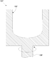
- FIG. 5 is a cross-sectional view showing an outline of a mold that can be depressurized as an example of a mold for temporarily forming the substrate forming raw material powder 11.
- the depressurizable mold 101 is made of, for example, a member such as graphite and has rotational symmetry.
- a decompression hole 103 is distributed and formed in the inner wall 102 of the mold 101 that can be decompressed.
- the decompression hole 103 is continuous with the decompression passage 104.
- a pressure-reducing passage 105 also passes through a rotary shaft 106 for rotating the pressure-reducible mold 101, and vacuuming can be performed from here.
- a porous filter (not shown) is preferably attached to the hole 103.
- a mold 101 ′ as shown in FIG. 6 may be used instead of the depressurizable mold 101 shown in FIG. 5.
- the mold 101 ' is made of a member such as graphite and has rotational symmetry. It has a rotation shaft 106 ′ for rotating the mold 101 ′, and the inner wall 102 ′ has no particular hole.
- the substrate forming raw material powder 11 is introduced into the inner wall 102 of the depressurizable mold 101, and the base forming raw material powder 11 is temporarily formed into a predetermined shape corresponding to the shape of the inner wall 102 of the depressurizable mold 101. Let it be a temporary molded body 41 (see FIG. 7). Specifically, while rotating the depressurizable mold 101, the substrate forming raw material powder 11 is gradually put into the inner wall 102 of the depressurizable mold 101 from a raw material powder hopper (not shown), and centrifugal force is used. To form into a container shape.
- the thickness of the temporary molded body 41 of the base body may be adjusted to a predetermined amount by bringing a plate-shaped inner mold (not shown) from the inside into contact with the rotating powder.
- the method for supplying the substrate forming raw material powder 11 to the depressurizable mold 101 is not particularly limited.
- a hopper provided with a stirring screw and a measuring feeder can be used.
- the substrate forming raw material powder 11 filled in the hopper is stirred with a stirring screw and supplied while adjusting the supply amount with a measuring feeder.
- the inner layer forming raw material powder 12 is introduced onto the inner surface of the substrate temporary molded body 41, and the substrate temporary Temporarily molding into a predetermined shape corresponding to the inner surface of the molded body 41 is used as an inner layer temporary molded body 46.
- the method is the same as that in the case of introducing the substrate forming raw material powder 11 described above. That is, while rotating the depressurizable mold 101, the inner layer forming raw material powder 12 is gradually introduced from the raw material powder hopper into the inner surface of the temporary molded body 41 of the base and formed into a container shape using centrifugal force ( (See FIG. 8).
- the base 51 and the inner layer 56 are formed by a discharge heating melting method.
- the pressure is reduced by the pressure reducing hole 103 formed in the depressurizable mold 101, thereby forming the temporary molded body 41 of the base body.
- the inner layer temporary molded body 46 is degassed by depressurization from the outer peripheral side of the base temporary molded body 41 and heated from the inside of the base temporary molded body 41 and the inner layer temporary molded body 46 by a discharge heating melting method. To do.
- the outer peripheral portion of the substrate temporary molded body 41 is used as a sintered body, and the inner portion of the substrate temporary molded body 41 and the inner layer temporary molded body 46 are used as molten glass bodies to form the substrate 51 and the inner layer 56. .
- the temporary molding body 41 and the inner layer temporary molding are performed by the electric discharge heating melting method without performing any particular pressure reduction.
- the base body 51 and the inner layer 56 are formed by heating from the inside of the body 46 at a high temperature.
- an embodiment in which the base 51 and the inner layer 56 are formed while reducing the pressure using the pressure-reducible mold 101 will be mainly described. However, the same applies to the case where the pressure is not reduced and the pressure is reduced.
- substrate 51 and the inner layer 56 can be formed by the process of.
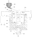
- the apparatus for forming the base 51 and the inner layer 56 includes a rotary motor (not shown), a discharge motor (not shown), and discharge heating melting (arc melting and arc discharge melting) in addition to the rotatable depressurizable mold 101 having rotational axis symmetry.
- a carbon electrode (carbon electrode) 212 serving as a heat source, an electric wire 212a, a high-voltage power supply unit 211, a lid 213, and the like.
- it includes components for adjusting the atmospheric gas supplied from the inside of the inner-layer temporary molded body 46, such as gas supply cylinders 411 and 412, a mixed gas supply pipe 420, a dehumidifier 430, a dew point thermometer 440, and the like. can do.
- hydrogen, helium, nitrogen or the like is supplied from the gas supply cylinders 411 and 412.
- a gas of 100% hydrogen when a gas of 100% hydrogen is used as the atmospheric gas, only one gas supply cylinder may be used.
- hydrogen or helium or a mixed gas thereof was added at 10 vol. It is also possible to prepare a gas (hydrogen / helium-containing atmosphere gas) contained in a ratio exceeding% in advance and supply this gas from a single gas cylinder.
- the dew point temperature is set to 15 ° C. to ⁇ 15 ° C. and the atmosphere is controlled in the range of ⁇ 2 ° C. of the set temperature. preferable. By doing in this way, it becomes possible to control the moisture content contained in the inner layer 56 and the OH group concentration combined with the silica glass network contained in the inner layer 56 to a constant value. Further, as the dew point temperature is lowered, OH groups can be reduced, and the concentration of OH groups is 1 to 50 wt. It is preferable to set it as ppm. However, the preferable dew point temperature can be determined depending on the use of the silica container.
- hydrogen is dehumidified to a predetermined dew point temperature or lower.
- helium or a mixed gas thereof is 10 vol.
- the atmosphere gas (hydrogen / helium-containing atmosphere gas) contained at a ratio exceeding% is started to be supplied from the inside of the base temporary molded body 41 and the inner layer temporary molded body 46. Specifically, as shown in FIG.
- hydrogen gas is supplied from a gas supply cylinder 411, and an inert gas other than hydrogen (for example, nitrogen (N 2 ), argon (Ar) is supplied from the gas supply cylinder 412. And helium (He)) are supplied and mixed, and supplied from the inside of the base temporary molded body 41 and the inner layer temporary molded body 46 through the mixed gas supply pipe 420.
- an inert gas other than hydrogen for example, nitrogen (N 2 ), argon (Ar) is supplied from the gas supply cylinder 412.
- helium (He) are supplied and mixed, and supplied from the inside of the base temporary molded body 41 and the inner layer temporary molded body 46 through the mixed gas supply pipe 420.
- symbol 510 shows the flow of mixed gas.
- the dew point temperature can be set by an appropriate dehumidifying device or the like, and an appropriate dew point thermometer or the like can be used to measure the dew point temperature.
- FIG. 9 shows a mode in which the dehumidifying device 430 and the dew point thermometer 440 are incorporated in the mixed gas supply pipe 420.
- the present invention is not limited to this, and the dew point temperature of the mixed gas can be set to a predetermined value range by dehumidification or the like. Good.
- the gas in the depressurizable mold 101 it is preferable to ventilate the gas in the depressurizable mold 101 as described above.
- This ventilation can be performed, for example, by letting the atmospheric gas in the depressurizable mold 101 escape from the gap of the lid 213 to the outside.
- symbol 520 shows the flow of atmospheric gas accompanying ventilation.
- the depressurizable mold 101 containing the base temporary molded body 41 and the inner layer temporary molded body 46 is rotated at a constant speed, and a degassing vacuum pump ( (Not shown) is activated, pressure is reduced from the outside of the temporary molded body 41 through the pressure reducing hole 103 and the pressure reducing passages 104 and 105, and charging is started between the carbon electrodes 212.
- a degassing vacuum pump (Not shown) is activated, pressure is reduced from the outside of the temporary molded body 41 through the pressure reducing hole 103 and the pressure reducing passages 104 and 105, and charging is started between the carbon electrodes 212.
- arc discharge (illustrated by reference numeral 220) is started between the carbon electrodes 212, the inner surface portions of the base temporary formed body 41 and the inner layer temporary formed body 46 are melted in a silica powder melting temperature range (about 1800 to 2000 ° C.). It is estimated) and melting starts from the outermost layer.
- the degree of vacuuming by the degassing vacuum pump increases (the pressure suddenly decreases), and the dissolved gas contained in the substrate forming raw material powder 11 and the inner layer forming raw material powder 12 is removed.
- the change to the fused silica glass layer proceeds from the inside to the outside while gassing.
- the timing of evacuation is important, and strong evacuation should not be performed before the inner surface layer inside the container is vitrified.
- the initial degree of decompression is not so high and the vacuuming is gradually strengthened as the inner surface is melted into glass.
- the inner layer and the inner half of the total thickness of the substrate are melted, the inner layer 56 is transparent silica glass, the inner peripheral side 51b of the substrate is a portion made of a transparent or translucent layer, and the outer peripheral portion of the substrate 51 (remaining) Heating by heating and depressurization by a vacuum pump are continued until 51a becomes sintered white opaque silica (opaque layer).
- the degree of vacuum is preferably 10 4 Pa or less, and more preferably 10 3 Pa or less. In this way, the silica container 71 of the present invention shown in FIG. 4 can be obtained.
- the inner layer forming step in the second embodiment as described later may be further performed once or a plurality of times so that the inner layer 56 is composed of a plurality of transparent silica glass layers having different purities and additives.
- FIG. 2 shows an outline of another example (second embodiment) of the method for producing the silica container 71 according to the present invention.
- the substrate forming raw material powder 11 and the inner layer forming raw material powder 12 which are silica particles are prepared. This step can be performed in the same manner as in the first embodiment described above.
- the base material forming powder 11 is introduced into a mold having rotational symmetry for molding.
- This step can also be performed in the same manner as in the first embodiment.
- the case where there is no need to perform discharge heating under reduced pressure is shown in FIG. A mold 101 ′ may be used.
- the substrate 51 is formed by a discharge heating melting method.
- the substrate temporary molded body 41 is replaced with the substrate temporary molded body 41 by reducing the pressure by the decompression hole 103 formed in the depressurizable mold 101. While depressurizing and degassing from the outer peripheral side, the substrate is heated from the inside of the temporary body of the base body by a discharge heating melting method. As a result, the outer peripheral portion of the base preform 41 is a sintered body, and the inner portion of the base preform 41 is a molten glass body to form the base 51.
- the substrate 51 is formed.
- substrate 51 is mainly demonstrated, reducing pressure using the mold 101 which can be pressure-reduced, However When not performing pressure reduction but performing at normal pressure, it is the same process except performing pressure reduction. Thus, the base 51 can be formed.
- the apparatus for forming the base 51 is a mold 101 that can be rotated and depressurized (or may be a mold 101 ′) having rotational axis symmetry.
- a rotation motor (not shown), and a carbon electrode (carbon electrode) 212 serving as a heat source for discharge heating melting (also referred to as arc melting or arc discharge melting), an electric wire 212a, a high-voltage power supply unit 211, a lid 213, and the like.
- the apparatus comprises components for adjusting the atmospheric gas supplied from the inside of the temporary molded body of the substrate, for example, gas supply cylinders 411 and 412, a mixed gas supply pipe 420, a dehumidifying device 430, a dew point thermometer 440, and the like. be able to.
- a hydrogen / helium-containing atmosphere that is set to a predetermined dew point temperature or less by dehumidification is used.
- the supply starts from the inside of the temporary molded body 41.
- hydrogen gas is supplied from a gas supply cylinder 411, and an inert gas other than hydrogen (for example, nitrogen (N 2 ), argon ( Ar) and helium (He)) are supplied and mixed, and supplied from the inside of the base preform 41 through the mixed gas supply pipe 420.
- symbol 510 shows the flow of mixed gas.
- the dew point temperature can be set by an appropriate dehumidifying device or the like, and an appropriate dew point thermometer or the like can be used to measure the dew point temperature.
- 10 and 11 show a mode in which the dehumidifying device 430 and the dew point thermometer 440 are incorporated in the mixed gas supply pipe 420, but the present invention is not limited to this, and the dew point temperature of the mixed gas is set to a predetermined value by dehumidification or the like. It only has to be in the range.
- the gas in the depressurizable mold 101 it is preferable to ventilate the gas in the depressurizable mold 101 as described above.
- This ventilation can be performed, for example, by letting the atmospheric gas in the depressurizable mold 101 escape from the gap of the lid 213 to the outside.
- symbol 520 shows the flow of atmospheric gas accompanying ventilation.
- the degassing vacuum pump (not shown) is started while rotating the depressurizable mold 101 containing the temporary molded body 41 of the base body at a constant speed. Then, the pressure is reduced from the outside of the temporary molded body 41 through the pressure reducing hole 103 and the pressure reducing passages 104 and 105, and charging is started between the carbon electrodes 212.
- the inner surface portion of the temporary body 41 of the base body becomes the melting temperature range of silica powder (estimated to be about 1800 to 2000 ° C.), and the outermost layer portion Melting begins from
- the degree of vacuuming by the degassing vacuum pump increases (the pressure suddenly decreases), and the fused silica glass layer degassed the dissolved gas contained in the substrate forming raw material powder 11.
- the timing of evacuation is important, and strong evacuation should not be performed before the inner surface layer inside the container is vitrified.
- the initial degree of decompression is not so high and the vacuuming is gradually strengthened as the inner surface is melted into glass. Then, the inner half of the entire thickness of the base body is melted, the inner peripheral side 51b of the base body becomes a portion made of a transparent or translucent layer, and the outer peripheral portion (the remaining outer half) 51a of the base body 51 is sintered white. Heating by applying electricity and depressurization by a vacuum pump are continued until opaque silica (opaque layer) is obtained.
- the degree of vacuum is preferably 10 4 Pa or less, and more preferably 10 3 Pa or less.
- the inner layer 56 is formed on the inner surface of the substrate 51 by heating at a high temperature from the inside.
- the inner layer 56 consist of several transparent silica glass layers from which purity and an additive differ by repeating this process.
- a method of forming the inner layer 56 will be described with reference to FIG.
- the apparatus for forming the inner layer 56 on the inner surface of the base 51 is the same as in the previous step, the rotatable depressurizable mold 101 on which the base 51 having rotational axis symmetry is installed, a rotary motor (not shown), And a raw material powder hopper 303 containing the inner layer forming raw material powder 12 for forming the inner layer 56, a stirring screw 304, a measuring feeder 305, a carbon electrode 212 serving as a heat source for discharge heating and melting, an electric wire 212a, a high voltage power supply unit 211, It consists of a lid 213 and the like.
- gas supply cylinders 411 and 412, a mixed gas supply pipe 420, a dehumidifier 430, a dew point thermometer 440, and the like may be further provided as in the previous step.
- the depressurizable mold 101 is set to a predetermined rotational speed, and a high voltage is gradually applied from the high-voltage power supply unit 211, and at the same time, the inner layer 56 is gradually formed from the raw material hopper 303.
- the inner layer forming raw material powder (high purity silica powder) 12 is sprayed from the upper part of the substrate 51.
- the discharge is started between the carbon electrodes 212, and the inside of the substrate 51 is in the silica powder melting temperature range (estimated to be about 1800 to 2000 ° C.), so that the dispersed inner layer forming raw material powder 12 is fused with silica.
- the particles adhere to the inner surface of the substrate 51.
- the carbon electrode 212, the raw material powder inlet, and the lid 213 installed in the upper opening of the base 51 have a mechanism that allows the position of the base 51 to be changed to some extent. By changing these positions, the base The inner layer 56 can be formed on the entire inner surface 51 with a uniform thickness.
- the step of forming the inner layer 56 by this discharge heating and melting method is preferably performed in an atmosphere set to a dew point temperature of 15 ° C. to ⁇ 15 ° C. and controlled within a range of ⁇ 2 ° C. of the set temperature.
- a dew point temperature 15 ° C. to ⁇ 15 ° C. and controlled within a range of ⁇ 2 ° C. of the set temperature.
- hydrogen gas is supplied from a gas supply cylinder 411, and an inert gas other than hydrogen (eg, nitrogen, argon, helium) is supplied from the gas supply cylinder 412 and mixed.
- the gas can be supplied from the inside of the base 51 through the mixed gas supply pipe 420.
- symbol 510 shows the flow of mixed gas.
- the gas in the depressurizable mold 101 can be ventilated. This ventilation can be performed, for example, by letting the atmospheric gas in the depressurizable mold 101 escape from the gap of the lid 213 to the outside.
- symbol 520 shows the flow of atmospheric gas accompanying ventilation.
- the silica container 71 according to the present invention shown in FIG. 4 can be manufactured.
- Example 1 In accordance with the method for producing a silica container of the present invention shown in FIG. 1 (first embodiment), a silica container was produced as follows.
- the purity of 99.999 wt. %, Natural quartz powder having a particle size of 50 to 500 ⁇ m was prepared.
- the raw material powder 12 for inner layer formation was prepared according to the procedure as shown in FIG. Specifically, first, a purity of 99.999 wt. %, And natural quartz powder having a particle diameter of 50 to 500 ⁇ m was prepared (FIG. 3 (1)).
- this natural quartz powder was immersed in an ethyl alcohol aqueous solution of barium nitrate having a predetermined concentration, and then heat-dried at 200 ° C. for 50 hours in a clean oven (FIG. 3 (2)).
- the raw material powder 12 for inner layer formation was obtained (FIG. 3 (3)).
- the substrate forming raw material powder 11 and the inner layer forming raw material powder 12 were integrally and temporarily formed as follows in a mold 101 as shown in FIG. First, while rotating a rotating cylindrical graphite depressurizable mold 101 having a decompression hole 103 formed in the inner wall 102, the substrate forming raw material powder 11 is introduced into the inner wall 102 of the mold to have a predetermined thickness. Then, the inner layer forming raw material powder 12 was added to form an inner layer temporary molded body 46 on the inner surface of the base temporary molded body 41 (see FIG. 8). Next, the atmosphere inside the temporary molded body 41 of the base and the temporary molded body 46 of the inner layer was changed to H 2 30 vol. %, He70 vol. % Of the mixed gas atmosphere.
- the dew point is 10 ° C. ⁇ 2 ° C., that is, in the range of 8 ° C. to 12 ° C., while gradually depressurizing and degassing the temporary molded body 41 of the base and the temporary molded body 46 of the inner layer with a vacuum pump from the outside of the mold 101.
- both temporary molded bodies were sintered and melted by the carbon electrode discharge heating melting method (arc discharge heating) (see FIG. 9).
- Example 2 In the same manner as in Example 1, except that the amount of Ba dope into the inner layer forming raw material powder 12 was approximately doubled, the silica container 71 was produced.
- Example 3 In the same manner as in Example 1, except that the amount of Ba dope into the inner layer forming raw material powder 12 was about four times the concentration, and Al was also doped at the same time, to produce a silica container 71.
- Example 4 As in Example 1, except that the amount of Ba dope into the inner layer forming raw material powder 12 was about 8 times the concentration and Al was also doped at the same time to produce a silica container 71.
- Example 5 As in Example 2, except that the atmosphere during heating under reduced pressure arc discharge of both temporary molded bodies was H 2 100 vol.
- the silica container 71 was manufactured as%.
- Example 6 As in Example 2, except that the atmosphere at the time of reduced-pressure arc discharge heating of both temporary molded bodies was H 2 50 vol. %, N 2 50 vol.
- the silica container 71 was manufactured as%.
- the silica container 71 was manufactured according to the method for manufacturing a silica container shown in FIG. 2 (second embodiment). First, the purity of 99.999 wt. %, Natural quartz powder having a particle size of 50 to 500 ⁇ m was prepared. Moreover, the raw material powder 12 for inner layer formation was prepared according to the procedure as shown in FIG. Specifically, first, a purity of 99.999 wt. %, And natural quartz powder having a particle diameter of 50 to 500 ⁇ m was prepared (FIG. 3 (1)). Next, this natural quartz powder was immersed in an ethyl alcohol aqueous solution of barium nitrate having a predetermined concentration, and then heat-dried at 200 ° C. for 50 hours in a clean oven (FIG. 3 (2)). Thus, the raw material powder 12 for inner layer formation was obtained (FIG. 3 (3)).
- the raw material powder 11 for substrate formation was temporarily formed in the mold 101 as shown in FIG. That is, while rotating a rotating cylindrical graphite depressurizable mold 101 having a decompression hole 103 formed in the inner wall 102, the substrate forming raw material powder 11 is introduced into the inner wall 102 of the mold to have a predetermined thickness. (See FIG. 7).
- the atmosphere inside the temporary molded body 41 of the base was changed to H 2 30 vol. %, He70 vol. % And the dew point temperature was controlled at 10 ° C. ⁇ 2 ° C.
- the base 51 was sintered and melted to form the base 51 by arc discharge heating under reduced pressure.
- the inner layer 56 was formed by arc discharge heating at normal pressure while spraying the inner layer forming raw material powder 12 from the upper part of the mold 101.
- the silica container 71 was manufactured.
- Example 8 As in Example 7, except that the atmosphere at the time of substrate formation was H 2 30 vol. %, N 2 70 vol.
- the silica container 71 was manufactured as%.
- Example 9 As in Example 2, except that the atmosphere during heating under reduced pressure arc discharge of both temporary molded bodies was H 2 15 vol. %, N 2 85 vol.
- the silica container 71 was manufactured as%.
- Example 10 As in Example 2, except that the atmosphere at the time of reduced-pressure arc discharge heating of both temporary molded bodies was He15 vol. %, N 2 85 vol.
- the silica container 71 was manufactured as%.
- a silica container (silica crucible) was produced in accordance with a conventional method.
- the raw material powder for forming the substrate and the raw material powder for forming the inner layer a particle diameter of 50 to 500 ⁇ m and a purity of 99.9999 wt. % High-purity quartz powder, particle size 50-300 ⁇ m, purity 99.9999 wt. % Cristobalite powder was prepared.
- the substrate is formed by atmospheric pressure arc heating in air that is not adjusted for humidity, and the inner layer is melted by atmospheric pressure arc heating in the same air while spraying raw material powder from the top of the mold. Formed.
- Comparative Example 3 As in Comparative Example 1, except that Ba is 3000 wt.
- the silica container was manufactured by performing high concentration dope with ppm.
- Comparative Example 4 Similar to Comparative Example 2, except that the raw material powder for substrate formation was purified to 99.99 wt. % Of the low-purity product, and the inner layer forming raw material powder was changed to high-purity synthetic cristobalite powder with Ba 100 wt. A silica container was produced using the ppm-doped material.
- Example 5 As in Example 2, except that the atmosphere at the time of reduced-pressure arc discharge heating of both the base and inner layer temporary molded bodies was H 2 5 vol. %, N 2 95 vol.
- the silica container 71 was manufactured as%.
- Example 6 (Comparative Example 6) As in Example 2, except that the atmosphere at the time of reduced-pressure arc discharge heating of both the base and inner layer temporary molded bodies was He5 vol. %, N 2 95 vol. The silica container 71 was manufactured as%.
- Particle size measurement method for each raw material powder Two-dimensional shape observation and area measurement of each raw material powder were performed with an optical microscope or an electron microscope. Next, assuming that the shape of the particle is a perfect circle, the diameter was calculated from the area value. This method was repeated statistically to obtain a value within the range of the particle size (in this range, 99 wt.% Or more of the raw material powder was included).
- Dew point temperature measurement Measured with a dew point thermometer. In addition, about each Example, it measured with the dew point thermometer 440 installed in the mixed gas supply pipe
- Impurity metal element concentration analysis When the impurity metal element concentration is relatively low (the glass is highly pure), plasma emission analysis (ICP-AES, Inductively Coupled Plasma-Atomic Emission Spectroscopy) or plasma mass spectrometry (ICP-MS, Inductively Coupled Pladded) When the impurity metal element concentration is relatively high (the glass is of low purity), atomic absorption spectrophotometry (AAS, Atomic Absorption Spectroscopy) was used.
- ICP-AES Inductively Coupled Plasma-Atomic Emission Spectroscopy
- ICP-MS Inductively Coupled Pladded
- Layer thickness measurement The thickness of the substrate and the inner layer was determined by measuring the cross section of the container at half the full height (200 mm height) of the side wall of the silica container.
- OH group concentration measurement Samples were cut and polished from the transparent portion of the substrate and the inner layer, and each was performed by infrared absorption spectrophotometry. Conversion to the OH group concentration follows the literature below. Dodd, D.D. M.M. and Fraser, D.A. B. (1966) “Optical determination of OH in fused silica.” Journal of Applied Physics, vol. 37, P.I. 3911.
- Water vapor gas emission measurement The amount of gas released from a granular silica glass sample adjusted to a particle size of 100 ⁇ m to 1 mm at 1000 ° C. under vacuum was measured with a mass spectrometer. Details follow the literature below. Water molecules H 2 O was expressed as the number of released molecules per unit weight (water molecules / g glass), assuming that all of the water molecules were released. Nasu, S .; et al. (1990) “Gas release of various kinds of vitreous silica”, Journal of Illuminating Engineering of Japan, vol. 74, no. 9, pp. 595-600.
- Light transmittance measurement A glass sample having dimensions of 5 mm ⁇ 5 mm ⁇ thickness of 11 mm was cut out from the inner layer, and both end faces were finished with a parallel optical polishing of 10 mm thickness (surface accuracy 1 / 20 ⁇ , wavelength 633 nm). After that, the visible light transmittance meter using a mercury lamp as a light source is used to measure the linear transmittance of the glass sample at 600 nm (the incident light is 100%, the reflection of the sample surface, the back reflection inside the sample, and the absorption of the sample itself). This is a value obtained by subtracting, and is called Optical transmission). The theoretical transmittance is a maximum of 93.2%. Since incident light is scattered by fine bubbles, fine particles, clusters, etc. in the glass sample, the value of light transmittance is determined by the fact that various dissolved elements are dissolved in the silica glass without bubbles and uniformly. It is effective for.
- Silicon single crystal continuous pulling (multi pulling) evaluation In the produced silica container, the purity was 99.9999999 wt. % Metal polysilicon was added, the temperature was raised to obtain a silicon melt, and then the silicon single crystal was pulled three times repeatedly (multi-pulling), and the success rate of single crystal growth was evaluated.
- the pulling conditions were as follows: the inside of the CZ apparatus was an argon (Ar) gas 100% atmosphere at a pressure of 10 3 Pa, the pulling rate was 1 mm / min, the rotation speed was 10 rpm, the silicon single crystal dimensions were 150 mm in diameter and 150 mm in length. The operation time for one batch was about 12 hours.
- the evaluation classification of the success rate of three times of single crystal growth was as follows. Successful 3 times ⁇ (Good) Successful ⁇ (Slightly bad) 1 time or less x (defect)
- etching resistance of silica containers From the silica container side wall of the lower part of the silica container after the multi-pulling of the silicon single crystal three times, the inner wall surface had all the thicknesses in the thickness direction so that the dimension of the inner wall surface was 100 mm ⁇ 100 mm. The sample was cut out as it was. Next, the etching amount of the inner wall portion of the inner layer was determined by measuring the sample cross section with a scale. The etched thickness of the inner layer is less than 3 mm ⁇ (good) The etched thickness of the inner layer is 3 mm to less than 5 mm. Etched thickness of inner layer is 5mm or more x (defect)
- Manufacturing cost (relative) evaluation of silica container The production cost of the silica container was evaluated. In particular, the total values of silica raw material costs, melting energy costs, etc. were relatively evaluated. Conventional production costs were based on Comparative Example 2. Low cost ⁇ (Less than 50% of conventional manufacturing cost) Medium cost ⁇ (50 to less than 100% of conventional manufacturing cost) Cost is high ⁇ (Conventional manufacturing cost is 100%)
- Tables 1 to 8 below summarize the production conditions, measured physical property values, and evaluation results of the silica containers produced in Examples 1 to 10 and Comparative Examples 1 to 6.
- the present invention is not limited to the above embodiment.
- the above embodiment is merely an example, and the present invention has the same configuration as that of the technical idea described in the claims of the present invention, and any device that exhibits the same function and effect is the present invention. It is included in the technical scope of the invention.
Priority Applications (5)
| Application Number | Priority Date | Filing Date | Title |
|---|---|---|---|
| KR1020117017618A KR101333190B1 (ko) | 2009-12-10 | 2010-10-19 | 실리카 용기 및 그 제조 방법 |
| CN201080006326.5A CN102301041B (zh) | 2009-12-10 | 2010-10-19 | 二氧化硅容器及其制造方法 |
| EP10835634.6A EP2511402A4 (en) | 2009-12-10 | 2010-10-19 | Silica vessel and process for production thereof |
| US13/145,063 US20110272322A1 (en) | 2009-12-10 | 2010-10-19 | Silica container and method for producing the same |
| US13/861,700 US9403620B2 (en) | 2009-12-10 | 2013-04-12 | Silica container and method for producing the same |
Applications Claiming Priority (2)
| Application Number | Priority Date | Filing Date | Title |
|---|---|---|---|
| JP2009280417A JP4951057B2 (ja) | 2009-12-10 | 2009-12-10 | シリカ容器及びその製造方法 |
| JP2009-280417 | 2009-12-10 |
Related Child Applications (2)
| Application Number | Title | Priority Date | Filing Date |
|---|---|---|---|
| US13/145,063 A-371-Of-International US20110272322A1 (en) | 2009-12-10 | 2010-10-19 | Silica container and method for producing the same |
| US13/861,700 Division US9403620B2 (en) | 2009-12-10 | 2013-04-12 | Silica container and method for producing the same |
Publications (1)
| Publication Number | Publication Date |
|---|---|
| WO2011070703A1 true WO2011070703A1 (ja) | 2011-06-16 |
Family
ID=44145271
Family Applications (1)
| Application Number | Title | Priority Date | Filing Date |
|---|---|---|---|
| PCT/JP2010/006179 WO2011070703A1 (ja) | 2009-12-10 | 2010-10-19 | シリカ容器及びその製造方法 |
Country Status (7)
| Country | Link |
|---|---|
| US (2) | US20110272322A1 (ko) |
| EP (1) | EP2511402A4 (ko) |
| JP (1) | JP4951057B2 (ko) |
| KR (1) | KR101333190B1 (ko) |
| CN (1) | CN102301041B (ko) |
| TW (1) | TWI405728B (ko) |
| WO (1) | WO2011070703A1 (ko) |
Cited By (2)
| Publication number | Priority date | Publication date | Assignee | Title |
|---|---|---|---|---|
| JP2011032147A (ja) * | 2009-08-05 | 2011-02-17 | Shinetsu Quartz Prod Co Ltd | シリカ容器及びその製造方法 |
| US20140283737A1 (en) * | 2012-01-13 | 2014-09-25 | Shin-Etsu Quartz Products Co., Ltd. | Single-crystal silicon pulling silica container and method for producing the same |
Families Citing this family (29)
| Publication number | Priority date | Publication date | Assignee | Title |
|---|---|---|---|---|
| JP4922355B2 (ja) * | 2009-07-15 | 2012-04-25 | 信越石英株式会社 | シリカ容器及びその製造方法 |
| JP5782996B2 (ja) * | 2011-11-01 | 2015-09-24 | 信越半導体株式会社 | 単結晶の製造方法 |
| MX2014010334A (es) | 2012-02-28 | 2014-09-22 | Corning Inc | Articulos de vidrio con revestimientos de baja friccion. |
| US10737973B2 (en) | 2012-02-28 | 2020-08-11 | Corning Incorporated | Pharmaceutical glass coating for achieving particle reduction |
| US11497681B2 (en) | 2012-02-28 | 2022-11-15 | Corning Incorporated | Glass articles with low-friction coatings |
| WO2013171937A1 (ja) | 2012-05-15 | 2013-11-21 | 信越石英株式会社 | 単結晶シリコン引き上げ用シリカ容器及びその製造方法 |
| EP2725122A4 (en) | 2012-05-16 | 2015-04-08 | Shinetsu Quartz Prod | SILICA CONTAINER FOR PREPARING SINGLE CRYSTALLINE SILICON AND METHOD FOR MANUFACTURING THE SAME |
| JP6257099B2 (ja) | 2012-06-07 | 2018-01-10 | コーニング インコーポレイテッド | 耐層間剥離性ガラス容器 |
| US10273048B2 (en) | 2012-06-07 | 2019-04-30 | Corning Incorporated | Delamination resistant glass containers with heat-tolerant coatings |
| US9034442B2 (en) | 2012-11-30 | 2015-05-19 | Corning Incorporated | Strengthened borosilicate glass containers with improved damage tolerance |
| US10117806B2 (en) | 2012-11-30 | 2018-11-06 | Corning Incorporated | Strengthened glass containers resistant to delamination and damage |
| CN105308435A (zh) * | 2013-06-30 | 2016-02-03 | 胜高股份有限公司 | 适于单晶硅提拉用石英玻璃坩埚的制造的石英粉的评估方法 |
| MX2017002898A (es) | 2014-09-05 | 2017-10-11 | Corning Inc | Artículos de vidrio y métodos para mejorar la confiabilidad de artículos de vidrio. |
| MX2017006945A (es) * | 2014-11-26 | 2017-08-16 | Corning Inc | Metodos para producir recipientes de vidrio fortalecidos y durables. |
| JP6480827B2 (ja) * | 2015-08-03 | 2019-03-13 | 信越石英株式会社 | 水素ドープシリカ粉の保管方法及びシリコン単結晶引上げ用石英ガラスるつぼの製造方法 |
| EP3150564B1 (en) | 2015-09-30 | 2018-12-05 | Corning Incorporated | Halogenated polyimide siloxane chemical compositions and glass articles with halogenated polylmide siloxane low-friction coatings |
| WO2017103121A2 (de) | 2015-12-18 | 2017-06-22 | Heraeus Quarzglas Gmbh & Co. Kg | Herstellung eines opaken quarzglaskörpers |
| EP3390304B1 (de) | 2015-12-18 | 2023-09-13 | Heraeus Quarzglas GmbH & Co. KG | Sprühgranulieren von siliziumdioxid bei der herstellung von quarzglas |
| JP6984897B2 (ja) | 2015-12-18 | 2021-12-22 | ヘレウス クワルツグラス ゲーエムベーハー ウント コンパニー カーゲー | 石英ガラス調製時のケイ素含有量の増大 |
| WO2017103153A1 (de) | 2015-12-18 | 2017-06-22 | Heraeus Quarzglas Gmbh & Co. Kg | Glasfasern und vorformen aus quarzglas mit geringem oh-, cl- und al-gehalt |
| CN109153593A (zh) | 2015-12-18 | 2019-01-04 | 贺利氏石英玻璃有限两合公司 | 合成石英玻璃粉粒的制备 |
| JP6940236B2 (ja) * | 2015-12-18 | 2021-09-22 | ヘレウス クワルツグラス ゲーエムベーハー ウント コンパニー カーゲー | 溶融炉内での露点監視による石英ガラス体の調製 |
| KR20180095622A (ko) | 2015-12-18 | 2018-08-27 | 헤래우스 크바르츠글라스 게엠베하 & 컴파니 케이지 | 내화성 금속으로 제조된 용융 도가니에서 실리카 유리 제품의 제조 |
| US11339076B2 (en) | 2015-12-18 | 2022-05-24 | Heraeus Quarzglas Gmbh & Co. Kg | Preparation of carbon-doped silicon dioxide granulate as an intermediate in the preparation of quartz glass |
| TWI794150B (zh) | 2015-12-18 | 2023-03-01 | 德商何瑞斯廓格拉斯公司 | 自二氧化矽顆粒製備石英玻璃體 |
| WO2017103166A2 (de) | 2015-12-18 | 2017-06-22 | Heraeus Quarzglas Gmbh & Co. Kg | Herstellung eines quarzglaskörpers in einem mehrkammerofen |
| KR102243264B1 (ko) * | 2018-12-13 | 2021-04-21 | 쿠어스택 가부시키가이샤 | 실리카 유리 도가니 및 그의 제조 방법 |
| JP7280160B2 (ja) * | 2018-12-13 | 2023-05-23 | モメンティブ・テクノロジーズ・山形株式会社 | シリカガラスルツボ |
| DE102020000701A1 (de) * | 2020-02-03 | 2021-08-05 | Siltronic Ag | Quarzglastiegel zur Herstellung von Siliciumkristallen und Verfahren zur Herstellung von Quarzglastiegel |
Citations (14)
| Publication number | Priority date | Publication date | Assignee | Title |
|---|---|---|---|---|
| JPH0422861A (ja) | 1990-05-17 | 1992-01-27 | Matsushita Seiko Co Ltd | 炭酸ガス検知装置 |
| JPH0729871A (ja) | 1993-06-25 | 1995-01-31 | Toshiba Corp | 表面処理方法および表面処理装置 |
| JPH082932A (ja) | 1994-06-20 | 1996-01-09 | Shinetsu Quartz Prod Co Ltd | 石英ガラスルツボとその製造方法 |
| JPH08268727A (ja) | 1994-11-15 | 1996-10-15 | General Electric Co <Ge> | 融解石英るつぼ及びその製造方法 |
| JPH0920586A (ja) | 1995-06-30 | 1997-01-21 | Toshiba Ceramics Co Ltd | シリコン単結晶引上げ用石英ガラスルツボの製造方法 |
| JP2000159593A (ja) * | 1998-11-24 | 2000-06-13 | Toshiba Ceramics Co Ltd | 石英ガラスるつぼの製造方法 |
| JP2000344536A (ja) | 1999-06-01 | 2000-12-12 | Toshiba Ceramics Co Ltd | 石英ガラスルツボおよびその製造方法 |
| JP2002362932A (ja) | 2001-03-24 | 2002-12-18 | Shinetsu Quartz Prod Co Ltd | SiO2含有複合材料の製造方法、その製造方法により得られる複合材料及び複合材料の使用 |
| JP2004002082A (ja) * | 2002-05-30 | 2004-01-08 | Japan Siper Quarts Corp | 石英ガラスルツボとその製造方法 |
| JP2004131380A (ja) | 2002-09-20 | 2004-04-30 | Heraeus Quarzglas Gmbh & Co Kg | 不透明石英ガラス複合材の製造方法、前記方法による複合材、およびその利用法 |
| JP2005145731A (ja) * | 2003-11-12 | 2005-06-09 | Kuramoto Seisakusho Co Ltd | 結晶化石英ルツボ |
| JP2007091532A (ja) * | 2005-09-29 | 2007-04-12 | Toshiba Ceramics Co Ltd | シリカガラスルツボ |
| JP2007326780A (ja) | 2007-09-18 | 2007-12-20 | Shinetsu Quartz Prod Co Ltd | シリコン単結晶引上げ用石英ガラスルツボの製造方法 |
| JP2008081398A (ja) * | 2006-09-28 | 2008-04-10 | Heraeus Shin-Etsu America Inc | バリウムドープされた内壁を有するシリカガラスるつぼ |
Family Cites Families (19)
| Publication number | Priority date | Publication date | Assignee | Title |
|---|---|---|---|---|
| US2038627A (en) * | 1935-07-18 | 1936-04-28 | Corning Glass Works | Method of making glass |
| US4935046A (en) | 1987-12-03 | 1990-06-19 | Shin-Etsu Handotai Company, Limited | Manufacture of a quartz glass vessel for the growth of single crystal semiconductor |
| EP0831060B1 (en) * | 1995-05-26 | 2003-12-03 | Mitsubishi Chemical Corporation | Synthetic quartz glass powder, quartz glass moldings, high purity tetraalkoxysilane, and production methods thereof |
| DE19962449C2 (de) * | 1999-12-22 | 2003-09-25 | Heraeus Quarzglas | Quarzglastiegel und Verfahren für seine Herstellung |
| JP4447738B2 (ja) * | 2000-05-31 | 2010-04-07 | 信越石英株式会社 | 多層構造の石英ガラスルツボの製造方法 |
| US20030012899A1 (en) * | 2001-07-16 | 2003-01-16 | Heraeus Shin-Etsu America | Doped silica glass crucible for making a silicon ingot |
| US7118789B2 (en) * | 2001-07-16 | 2006-10-10 | Heraeus Shin-Etsu America | Silica glass crucible |
| JP4117641B2 (ja) * | 2001-11-26 | 2008-07-16 | ジャパンスーパークォーツ株式会社 | 合成石英粉の処理方法およびその石英ガラス製品 |
| JP4453954B2 (ja) * | 2003-02-28 | 2010-04-21 | 信越石英株式会社 | シリコン単結晶引上げ用石英ガラスルツボの製造方法および該製造方法で製造された石英ガラスルツボ |
| JP2006021985A (ja) * | 2004-06-10 | 2006-01-26 | Kuramoto Seisakusho Co Ltd | 石英ルツボ |
| US7427327B2 (en) * | 2005-09-08 | 2008-09-23 | Heraeus Shin-Etsu America, Inc. | Silica glass crucible with barium-doped inner wall |
| JP4918473B2 (ja) * | 2007-12-14 | 2012-04-18 | ジャパンスーパークォーツ株式会社 | 高強度を有する大径シリコン単結晶インゴット引上げ用高純度石英ガラスルツボ |
| JP5106340B2 (ja) * | 2008-09-30 | 2012-12-26 | 信越石英株式会社 | シリカ容器及びその製造方法 |
| JP5167073B2 (ja) * | 2008-11-05 | 2013-03-21 | 信越石英株式会社 | シリカ容器及びその製造方法 |
| JP5118007B2 (ja) * | 2008-12-11 | 2013-01-16 | 信越石英株式会社 | シリカ容器及びその製造方法 |
| CN102224113B (zh) * | 2009-04-28 | 2013-11-13 | 信越石英株式会社 | 二氧化硅容器及其制造方法 |
| JP4903288B2 (ja) * | 2009-05-26 | 2012-03-28 | 信越石英株式会社 | シリカ容器及びその製造方法 |
| JP4951040B2 (ja) * | 2009-08-05 | 2012-06-13 | 信越石英株式会社 | シリカ容器及びその製造方法 |
| JP4969632B2 (ja) * | 2009-10-14 | 2012-07-04 | 信越石英株式会社 | シリカ粉及びシリカ容器並びにそれらの製造方法 |
-
2009
- 2009-12-10 JP JP2009280417A patent/JP4951057B2/ja active Active
-
2010
- 2010-10-19 US US13/145,063 patent/US20110272322A1/en not_active Abandoned
- 2010-10-19 KR KR1020117017618A patent/KR101333190B1/ko active IP Right Grant
- 2010-10-19 EP EP10835634.6A patent/EP2511402A4/en not_active Withdrawn
- 2010-10-19 WO PCT/JP2010/006179 patent/WO2011070703A1/ja active Application Filing
- 2010-10-19 CN CN201080006326.5A patent/CN102301041B/zh active Active
- 2010-10-27 TW TW099136790A patent/TWI405728B/zh active
-
2013
- 2013-04-12 US US13/861,700 patent/US9403620B2/en active Active
Patent Citations (14)
| Publication number | Priority date | Publication date | Assignee | Title |
|---|---|---|---|---|
| JPH0422861A (ja) | 1990-05-17 | 1992-01-27 | Matsushita Seiko Co Ltd | 炭酸ガス検知装置 |
| JPH0729871A (ja) | 1993-06-25 | 1995-01-31 | Toshiba Corp | 表面処理方法および表面処理装置 |
| JPH082932A (ja) | 1994-06-20 | 1996-01-09 | Shinetsu Quartz Prod Co Ltd | 石英ガラスルツボとその製造方法 |
| JPH08268727A (ja) | 1994-11-15 | 1996-10-15 | General Electric Co <Ge> | 融解石英るつぼ及びその製造方法 |
| JPH0920586A (ja) | 1995-06-30 | 1997-01-21 | Toshiba Ceramics Co Ltd | シリコン単結晶引上げ用石英ガラスルツボの製造方法 |
| JP2000159593A (ja) * | 1998-11-24 | 2000-06-13 | Toshiba Ceramics Co Ltd | 石英ガラスるつぼの製造方法 |
| JP2000344536A (ja) | 1999-06-01 | 2000-12-12 | Toshiba Ceramics Co Ltd | 石英ガラスルツボおよびその製造方法 |
| JP2002362932A (ja) | 2001-03-24 | 2002-12-18 | Shinetsu Quartz Prod Co Ltd | SiO2含有複合材料の製造方法、その製造方法により得られる複合材料及び複合材料の使用 |
| JP2004002082A (ja) * | 2002-05-30 | 2004-01-08 | Japan Siper Quarts Corp | 石英ガラスルツボとその製造方法 |
| JP2004131380A (ja) | 2002-09-20 | 2004-04-30 | Heraeus Quarzglas Gmbh & Co Kg | 不透明石英ガラス複合材の製造方法、前記方法による複合材、およびその利用法 |
| JP2005145731A (ja) * | 2003-11-12 | 2005-06-09 | Kuramoto Seisakusho Co Ltd | 結晶化石英ルツボ |
| JP2007091532A (ja) * | 2005-09-29 | 2007-04-12 | Toshiba Ceramics Co Ltd | シリカガラスルツボ |
| JP2008081398A (ja) * | 2006-09-28 | 2008-04-10 | Heraeus Shin-Etsu America Inc | バリウムドープされた内壁を有するシリカガラスるつぼ |
| JP2007326780A (ja) | 2007-09-18 | 2007-12-20 | Shinetsu Quartz Prod Co Ltd | シリコン単結晶引上げ用石英ガラスルツボの製造方法 |
Non-Patent Citations (3)
| Title |
|---|
| DODD, D. M.; FRASER, D. B.: "Optical determination of OH in fused silica", JOURNAL OF APPLIED PHYSICS, vol. 37, 1966, pages 3911 |
| NASU, S. ET AL.: "Gas release of various kinds of vitreous silica", JOURNAL OF ILLUMINATING ENGINEERING INSTITUTE OF JAPAN, vol. 74, no. 9, 1990, pages 595 - 600 |
| See also references of EP2511402A4 * |
Cited By (3)
| Publication number | Priority date | Publication date | Assignee | Title |
|---|---|---|---|---|
| JP2011032147A (ja) * | 2009-08-05 | 2011-02-17 | Shinetsu Quartz Prod Co Ltd | シリカ容器及びその製造方法 |
| US20140283737A1 (en) * | 2012-01-13 | 2014-09-25 | Shin-Etsu Quartz Products Co., Ltd. | Single-crystal silicon pulling silica container and method for producing the same |
| US9376761B2 (en) * | 2012-01-13 | 2016-06-28 | Shin-Etsu Quartz Products Co., Ltd. | Single-crystal silicon pulling silica container and method for producing the same |
Also Published As
| Publication number | Publication date |
|---|---|
| US20110272322A1 (en) | 2011-11-10 |
| CN102301041A (zh) | 2011-12-28 |
| KR101333190B1 (ko) | 2013-11-26 |
| CN102301041B (zh) | 2014-05-07 |
| US9403620B2 (en) | 2016-08-02 |
| EP2511402A4 (en) | 2017-06-07 |
| EP2511402A1 (en) | 2012-10-17 |
| JP4951057B2 (ja) | 2012-06-13 |
| JP2011121811A (ja) | 2011-06-23 |
| TW201119957A (en) | 2011-06-16 |
| US20130248408A1 (en) | 2013-09-26 |
| KR20110110250A (ko) | 2011-10-06 |
| TWI405728B (zh) | 2013-08-21 |
Similar Documents
| Publication | Publication Date | Title |
|---|---|---|
| JP4951057B2 (ja) | シリカ容器及びその製造方法 | |
| JP4969632B2 (ja) | シリカ粉及びシリカ容器並びにそれらの製造方法 | |
| JP4951040B2 (ja) | シリカ容器及びその製造方法 | |
| JP4907735B2 (ja) | シリカ容器及びその製造方法 | |
| JP4903288B2 (ja) | シリカ容器及びその製造方法 | |
| JP4922355B2 (ja) | シリカ容器及びその製造方法 | |
| EP2687623A1 (en) | Silica container for pulling up single crystal silicon, and method for manufacturing same | |
| JP5497247B1 (ja) | 単結晶シリコン引き上げ用シリカ容器及びその製造方法 | |
| JP5308594B1 (ja) | 単結晶シリコン引き上げ用シリカ容器及びその製造方法 | |
| JP5595615B2 (ja) | 単結晶シリコン引き上げ用シリカ容器及びその製造方法 |
Legal Events
| Date | Code | Title | Description |
|---|---|---|---|
| WWE | Wipo information: entry into national phase |
Ref document number: 201080006326.5 Country of ref document: CN |
|
| ENP | Entry into the national phase |
Ref document number: 20117017618 Country of ref document: KR Kind code of ref document: A |
|
| 121 | Ep: the epo has been informed by wipo that ep was designated in this application |
Ref document number: 10835634 Country of ref document: EP Kind code of ref document: A1 |
|
| NENP | Non-entry into the national phase |
Ref country code: DE |
|
| WWE | Wipo information: entry into national phase |
Ref document number: 2010835634 Country of ref document: EP |