EP3150564B1 - Halogenated polyimide siloxane chemical compositions and glass articles with halogenated polylmide siloxane low-friction coatings - Google Patents
Halogenated polyimide siloxane chemical compositions and glass articles with halogenated polylmide siloxane low-friction coatings Download PDFInfo
- Publication number
- EP3150564B1 EP3150564B1 EP15290254.0A EP15290254A EP3150564B1 EP 3150564 B1 EP3150564 B1 EP 3150564B1 EP 15290254 A EP15290254 A EP 15290254A EP 3150564 B1 EP3150564 B1 EP 3150564B1
- Authority
- EP
- European Patent Office
- Prior art keywords
- coated glass
- glass article
- chemical composition
- low
- friction
- Prior art date
- Legal status (The legal status is an assumption and is not a legal conclusion. Google has not performed a legal analysis and makes no representation as to the accuracy of the status listed.)
- Active
Links
- 239000011521 glass Substances 0.000 title claims description 421
- 238000000576 coating method Methods 0.000 title claims description 168
- 239000000203 mixture Substances 0.000 title claims description 143
- 239000000126 substance Substances 0.000 title claims description 133
- 239000004642 Polyimide Substances 0.000 title claims description 131
- 229920001721 polyimide Polymers 0.000 title claims description 131
- KPUWHANPEXNPJT-UHFFFAOYSA-N disiloxane Chemical class [SiH3]O[SiH3] KPUWHANPEXNPJT-UHFFFAOYSA-N 0.000 title claims description 71
- 239000011248 coating agent Substances 0.000 claims description 149
- 239000000178 monomer Substances 0.000 claims description 89
- 239000007822 coupling agent Substances 0.000 claims description 60
- BLRPTPMANUNPDV-UHFFFAOYSA-N Silane Chemical compound [SiH4] BLRPTPMANUNPDV-UHFFFAOYSA-N 0.000 claims description 42
- 229910000077 silane Inorganic materials 0.000 claims description 41
- -1 siloxane moiety Chemical group 0.000 claims description 39
- 229920000642 polymer Polymers 0.000 claims description 33
- 238000000034 method Methods 0.000 claims description 31
- 150000001412 amines Chemical class 0.000 claims description 29
- 238000010438 heat treatment Methods 0.000 claims description 27
- 125000003118 aryl group Chemical group 0.000 claims description 25
- 239000002904 solvent Substances 0.000 claims description 18
- 230000005540 biological transmission Effects 0.000 claims description 15
- 150000008064 anhydrides Chemical class 0.000 claims description 10
- GPXCORHXFPYJEH-UHFFFAOYSA-N 3-[[3-aminopropyl(dimethyl)silyl]oxy-dimethylsilyl]propan-1-amine Chemical group NCCC[Si](C)(C)O[Si](C)(C)CCCN GPXCORHXFPYJEH-UHFFFAOYSA-N 0.000 claims description 8
- BEKFRNOZJSYWKZ-UHFFFAOYSA-N 4-[2-(4-aminophenyl)-1,1,1,3,3,3-hexafluoropropan-2-yl]aniline Chemical group C1=CC(N)=CC=C1C(C(F)(F)F)(C(F)(F)F)C1=CC=C(N)C=C1 BEKFRNOZJSYWKZ-UHFFFAOYSA-N 0.000 claims description 8
- 238000000151 deposition Methods 0.000 claims description 6
- 150000002576 ketones Chemical class 0.000 claims description 6
- 239000007787 solid Substances 0.000 claims description 6
- 239000000758 substrate Substances 0.000 claims description 5
- QHHKLPCQTTWFSS-UHFFFAOYSA-N 5-[2-(1,3-dioxo-2-benzofuran-5-yl)-1,1,1,3,3,3-hexafluoropropan-2-yl]-2-benzofuran-1,3-dione Chemical group C1=C2C(=O)OC(=O)C2=CC(C(C=2C=C3C(=O)OC(=O)C3=CC=2)(C(F)(F)F)C(F)(F)F)=C1 QHHKLPCQTTWFSS-UHFFFAOYSA-N 0.000 claims description 4
- QTBSBXVTEAMEQO-UHFFFAOYSA-M Acetate Chemical compound CC([O-])=O QTBSBXVTEAMEQO-UHFFFAOYSA-M 0.000 claims description 3
- 238000006116 polymerization reaction Methods 0.000 claims description 3
- PXGOKWXKJXAPGV-UHFFFAOYSA-N Fluorine Chemical compound FF PXGOKWXKJXAPGV-UHFFFAOYSA-N 0.000 claims description 2
- 229920001577 copolymer Polymers 0.000 claims description 2
- 229910052731 fluorine Inorganic materials 0.000 claims description 2
- 239000011737 fluorine Substances 0.000 claims description 2
- 239000010410 layer Substances 0.000 description 76
- 239000000243 solution Substances 0.000 description 38
- 238000011082 depyrogenation Methods 0.000 description 30
- 238000012360 testing method Methods 0.000 description 27
- 238000007906 compression Methods 0.000 description 22
- 230000006835 compression Effects 0.000 description 22
- 230000000052 comparative effect Effects 0.000 description 21
- 239000000523 sample Substances 0.000 description 21
- 238000007669 thermal treatment Methods 0.000 description 19
- OKKJLVBELUTLKV-UHFFFAOYSA-N Methanol Chemical compound OC OKKJLVBELUTLKV-UHFFFAOYSA-N 0.000 description 18
- AFHIIJICYLMCSH-VOTSOKGWSA-N 5-amino-2-[(e)-2-(4-benzamido-2-sulfophenyl)ethenyl]benzenesulfonic acid Chemical compound OS(=O)(=O)C1=CC(N)=CC=C1\C=C\C(C(=C1)S(O)(=O)=O)=CC=C1NC(=O)C1=CC=CC=C1 AFHIIJICYLMCSH-VOTSOKGWSA-N 0.000 description 15
- 150000004985 diamines Chemical class 0.000 description 15
- 238000010943 off-gassing Methods 0.000 description 15
- SECXISVLQFMRJM-UHFFFAOYSA-N N-Methylpyrrolidone Chemical compound CN1CCCC1=O SECXISVLQFMRJM-UHFFFAOYSA-N 0.000 description 14
- 238000011282 treatment Methods 0.000 description 13
- KFZMGEQAYNKOFK-UHFFFAOYSA-N Isopropanol Chemical compound CC(C)O KFZMGEQAYNKOFK-UHFFFAOYSA-N 0.000 description 12
- 125000001931 aliphatic group Chemical group 0.000 description 11
- 238000004108 freeze drying Methods 0.000 description 11
- 229920005575 poly(amic acid) Polymers 0.000 description 11
- 239000000843 powder Substances 0.000 description 11
- 230000008569 process Effects 0.000 description 11
- NXDMHKQJWIMEEE-UHFFFAOYSA-N 4-(4-aminophenoxy)aniline;furo[3,4-f][2]benzofuran-1,3,5,7-tetrone Chemical compound C1=CC(N)=CC=C1OC1=CC=C(N)C=C1.C1=C2C(=O)OC(=O)C2=CC2=C1C(=O)OC2=O NXDMHKQJWIMEEE-UHFFFAOYSA-N 0.000 description 10
- 238000005259 measurement Methods 0.000 description 10
- 229920003223 poly(pyromellitimide-1,4-diphenyl ether) Polymers 0.000 description 10
- XLYOFNOQVPJJNP-UHFFFAOYSA-N water Substances O XLYOFNOQVPJJNP-UHFFFAOYSA-N 0.000 description 9
- XKRFYHLGVUSROY-UHFFFAOYSA-N Argon Chemical compound [Ar] XKRFYHLGVUSROY-UHFFFAOYSA-N 0.000 description 8
- 238000005299 abrasion Methods 0.000 description 8
- 238000006243 chemical reaction Methods 0.000 description 8
- 125000006159 dianhydride group Chemical class 0.000 description 8
- 238000004519 manufacturing process Methods 0.000 description 8
- 238000004806 packaging method and process Methods 0.000 description 8
- 238000004383 yellowing Methods 0.000 description 8
- 238000009835 boiling Methods 0.000 description 7
- 230000009477 glass transition Effects 0.000 description 7
- 239000000413 hydrolysate Substances 0.000 description 7
- 239000008194 pharmaceutical composition Substances 0.000 description 7
- XEKOWRVHYACXOJ-UHFFFAOYSA-N Ethyl acetate Chemical compound CCOC(C)=O XEKOWRVHYACXOJ-UHFFFAOYSA-N 0.000 description 6
- YXFVVABEGXRONW-UHFFFAOYSA-N Toluene Chemical compound CC1=CC=CC=C1 YXFVVABEGXRONW-UHFFFAOYSA-N 0.000 description 6
- 239000003814 drug Substances 0.000 description 6
- 239000007789 gas Substances 0.000 description 6
- 229910052736 halogen Inorganic materials 0.000 description 6
- 150000002367 halogens Chemical class 0.000 description 6
- 150000003839 salts Chemical class 0.000 description 6
- 150000004756 silanes Chemical class 0.000 description 6
- 239000002356 single layer Substances 0.000 description 6
- 241000894007 species Species 0.000 description 6
- 238000005496 tempering Methods 0.000 description 6
- SJECZPVISLOESU-UHFFFAOYSA-N 3-trimethoxysilylpropan-1-amine Chemical compound CO[Si](OC)(OC)CCCN SJECZPVISLOESU-UHFFFAOYSA-N 0.000 description 5
- ZMXDDKWLCZADIW-UHFFFAOYSA-N N,N-Dimethylformamide Chemical compound CN(C)C=O ZMXDDKWLCZADIW-UHFFFAOYSA-N 0.000 description 5
- GTDPSWPPOUPBNX-UHFFFAOYSA-N ac1mqpva Chemical compound CC12C(=O)OC(=O)C1(C)C1(C)C2(C)C(=O)OC1=O GTDPSWPPOUPBNX-UHFFFAOYSA-N 0.000 description 5
- 239000002585 base Substances 0.000 description 5
- 238000005342 ion exchange Methods 0.000 description 5
- 238000002156 mixing Methods 0.000 description 5
- 230000002829 reductive effect Effects 0.000 description 5
- 238000005728 strengthening Methods 0.000 description 5
- CSCPPACGZOOCGX-UHFFFAOYSA-N Acetone Chemical compound CC(C)=O CSCPPACGZOOCGX-UHFFFAOYSA-N 0.000 description 4
- GOLCXWYRSKYTSP-UHFFFAOYSA-N Arsenious Acid Chemical compound O1[As]2O[As]1O2 GOLCXWYRSKYTSP-UHFFFAOYSA-N 0.000 description 4
- IJGRMHOSHXDMSA-UHFFFAOYSA-N Atomic nitrogen Chemical compound N#N IJGRMHOSHXDMSA-UHFFFAOYSA-N 0.000 description 4
- VYPSYNLAJGMNEJ-UHFFFAOYSA-N Silicium dioxide Chemical compound O=[Si]=O VYPSYNLAJGMNEJ-UHFFFAOYSA-N 0.000 description 4
- GWEVSGVZZGPLCZ-UHFFFAOYSA-N Titan oxide Chemical compound O=[Ti]=O GWEVSGVZZGPLCZ-UHFFFAOYSA-N 0.000 description 4
- XLOMVQKBTHCTTD-UHFFFAOYSA-N Zinc monoxide Chemical compound [Zn]=O XLOMVQKBTHCTTD-UHFFFAOYSA-N 0.000 description 4
- MCMNRKCIXSYSNV-UHFFFAOYSA-N Zirconium dioxide Chemical compound O=[Zr]=O MCMNRKCIXSYSNV-UHFFFAOYSA-N 0.000 description 4
- 239000000853 adhesive Substances 0.000 description 4
- 230000001070 adhesive effect Effects 0.000 description 4
- 229910052786 argon Inorganic materials 0.000 description 4
- 239000008367 deionised water Substances 0.000 description 4
- 238000002845 discoloration Methods 0.000 description 4
- 239000000463 material Substances 0.000 description 4
- LLHKCFNBLRBOGN-UHFFFAOYSA-N propylene glycol methyl ether acetate Chemical compound COCC(C)OC(C)=O LLHKCFNBLRBOGN-UHFFFAOYSA-N 0.000 description 4
- 238000010926 purge Methods 0.000 description 4
- 230000000717 retained effect Effects 0.000 description 4
- FZHAPNGMFPVSLP-UHFFFAOYSA-N silanamine Chemical compound [SiH3]N FZHAPNGMFPVSLP-UHFFFAOYSA-N 0.000 description 4
- 239000005361 soda-lime glass Substances 0.000 description 4
- 238000003756 stirring Methods 0.000 description 4
- XOLBLPGZBRYERU-UHFFFAOYSA-N tin dioxide Chemical compound O=[Sn]=O XOLBLPGZBRYERU-UHFFFAOYSA-N 0.000 description 4
- 231100000331 toxic Toxicity 0.000 description 4
- 230000002588 toxic effect Effects 0.000 description 4
- LVACOMKKELLCHJ-UHFFFAOYSA-N 3-trimethoxysilylpropylurea Chemical compound CO[Si](OC)(OC)CCCNC(N)=O LVACOMKKELLCHJ-UHFFFAOYSA-N 0.000 description 3
- CNODSORTHKVDEM-UHFFFAOYSA-N 4-trimethoxysilylaniline Chemical compound CO[Si](OC)(OC)C1=CC=C(N)C=C1 CNODSORTHKVDEM-UHFFFAOYSA-N 0.000 description 3
- HEMHJVSKTPXQMS-UHFFFAOYSA-M Sodium hydroxide Chemical compound [OH-].[Na+] HEMHJVSKTPXQMS-UHFFFAOYSA-M 0.000 description 3
- ZMANZCXQSJIPKH-UHFFFAOYSA-N Triethylamine Chemical compound CCN(CC)CC ZMANZCXQSJIPKH-UHFFFAOYSA-N 0.000 description 3
- 238000013019 agitation Methods 0.000 description 3
- 239000003708 ampul Substances 0.000 description 3
- 239000007864 aqueous solution Substances 0.000 description 3
- 229910052799 carbon Inorganic materials 0.000 description 3
- 230000008859 change Effects 0.000 description 3
- 239000008199 coating composition Substances 0.000 description 3
- 150000001875 compounds Chemical class 0.000 description 3
- 230000007423 decrease Effects 0.000 description 3
- 230000008021 deposition Effects 0.000 description 3
- 229940079593 drug Drugs 0.000 description 3
- 230000007613 environmental effect Effects 0.000 description 3
- 238000000806 fluorine-19 nuclear magnetic resonance spectrum Methods 0.000 description 3
- 150000002500 ions Chemical class 0.000 description 3
- 238000000879 optical micrograph Methods 0.000 description 3
- 238000002360 preparation method Methods 0.000 description 3
- 238000012545 processing Methods 0.000 description 3
- 238000000425 proton nuclear magnetic resonance spectrum Methods 0.000 description 3
- 239000011347 resin Substances 0.000 description 3
- 229920005989 resin Polymers 0.000 description 3
- 238000000926 separation method Methods 0.000 description 3
- 239000003039 volatile agent Substances 0.000 description 3
- ZWEHNKRNPOVVGH-UHFFFAOYSA-N 2-Butanone Chemical compound CCC(C)=O ZWEHNKRNPOVVGH-UHFFFAOYSA-N 0.000 description 2
- RZVAJINKPMORJF-UHFFFAOYSA-N Acetaminophen Chemical compound CC(=O)NC1=CC=C(O)C=C1 RZVAJINKPMORJF-UHFFFAOYSA-N 0.000 description 2
- ZOXJGFHDIHLPTG-UHFFFAOYSA-N Boron Chemical compound [B] ZOXJGFHDIHLPTG-UHFFFAOYSA-N 0.000 description 2
- OKTJSMMVPCPJKN-UHFFFAOYSA-N Carbon Chemical group [C] OKTJSMMVPCPJKN-UHFFFAOYSA-N 0.000 description 2
- FXHOOIRPVKKKFG-UHFFFAOYSA-N N,N-Dimethylacetamide Chemical compound CN(C)C(C)=O FXHOOIRPVKKKFG-UHFFFAOYSA-N 0.000 description 2
- 239000004677 Nylon Substances 0.000 description 2
- 239000002250 absorbent Substances 0.000 description 2
- 230000002745 absorbent Effects 0.000 description 2
- 150000001242 acetic acid derivatives Chemical class 0.000 description 2
- 239000002253 acid Substances 0.000 description 2
- 125000004423 acyloxy group Chemical group 0.000 description 2
- 239000003463 adsorbent Substances 0.000 description 2
- 239000005354 aluminosilicate glass Substances 0.000 description 2
- 239000012300 argon atmosphere Substances 0.000 description 2
- QVGXLLKOCUKJST-UHFFFAOYSA-N atomic oxygen Chemical compound [O] QVGXLLKOCUKJST-UHFFFAOYSA-N 0.000 description 2
- 230000008901 benefit Effects 0.000 description 2
- 150000001555 benzenes Chemical class 0.000 description 2
- 229910052796 boron Inorganic materials 0.000 description 2
- 239000005388 borosilicate glass Substances 0.000 description 2
- 230000015556 catabolic process Effects 0.000 description 2
- 239000000919 ceramic Substances 0.000 description 2
- 239000013626 chemical specie Substances 0.000 description 2
- 238000012669 compression test Methods 0.000 description 2
- 238000004090 dissolution Methods 0.000 description 2
- 238000001704 evaporation Methods 0.000 description 2
- 238000011049 filling Methods 0.000 description 2
- 230000001939 inductive effect Effects 0.000 description 2
- 230000036512 infertility Effects 0.000 description 2
- 229910010272 inorganic material Inorganic materials 0.000 description 2
- 239000011147 inorganic material Substances 0.000 description 2
- 229910052500 inorganic mineral Inorganic materials 0.000 description 2
- 239000007788 liquid Substances 0.000 description 2
- 238000011068 loading method Methods 0.000 description 2
- 239000011707 mineral Substances 0.000 description 2
- 210000003739 neck Anatomy 0.000 description 2
- 229910052757 nitrogen Inorganic materials 0.000 description 2
- 231100000252 nontoxic Toxicity 0.000 description 2
- 230000003000 nontoxic effect Effects 0.000 description 2
- 229920001778 nylon Polymers 0.000 description 2
- 238000006384 oligomerization reaction Methods 0.000 description 2
- 239000001301 oxygen Substances 0.000 description 2
- 229910052760 oxygen Inorganic materials 0.000 description 2
- 238000009512 pharmaceutical packaging Methods 0.000 description 2
- 239000002244 precipitate Substances 0.000 description 2
- 239000002243 precursor Substances 0.000 description 2
- 239000000047 product Substances 0.000 description 2
- YKYONYBAUNKHLG-UHFFFAOYSA-N propyl acetate Chemical compound CCCOC(C)=O YKYONYBAUNKHLG-UHFFFAOYSA-N 0.000 description 2
- 239000005297 pyrex Substances 0.000 description 2
- 239000000377 silicon dioxide Substances 0.000 description 2
- 229920002545 silicone oil Polymers 0.000 description 2
- 239000011124 type III (regular soda lime glass) Substances 0.000 description 2
- 230000004580 weight loss Effects 0.000 description 2
- WYTZZXDRDKSJID-UHFFFAOYSA-N (3-aminopropyl)triethoxysilane Chemical compound CCO[Si](OCC)(OCC)CCCN WYTZZXDRDKSJID-UHFFFAOYSA-N 0.000 description 1
- CRSBYNFDIUEGMW-UHFFFAOYSA-N (carbamoylamino)silylurea Chemical compound NC(=O)N[SiH2]NC(N)=O CRSBYNFDIUEGMW-UHFFFAOYSA-N 0.000 description 1
- 238000004293 19F NMR spectroscopy Methods 0.000 description 1
- 238000005160 1H NMR spectroscopy Methods 0.000 description 1
- GSVMCEUQHZAFKG-UHFFFAOYSA-N 2-triethoxysilylaniline Chemical compound CCO[Si](OCC)(OCC)C1=CC=CC=C1N GSVMCEUQHZAFKG-UHFFFAOYSA-N 0.000 description 1
- QKWSWOAGYACAGD-UHFFFAOYSA-N 3-(3-triethoxysilylpropoxy)aniline Chemical compound CCO[Si](OCC)(OCC)CCCOC1=CC=CC(N)=C1 QKWSWOAGYACAGD-UHFFFAOYSA-N 0.000 description 1
- HUPGCAGBHBJUJC-UHFFFAOYSA-N 3-(3-trimethoxysilylpropoxy)aniline Chemical compound CO[Si](OC)(OC)CCCOC1=CC=CC(N)=C1 HUPGCAGBHBJUJC-UHFFFAOYSA-N 0.000 description 1
- XUSNPFGLKGCWGN-UHFFFAOYSA-N 3-[4-(3-aminopropyl)piperazin-1-yl]propan-1-amine Chemical compound NCCCN1CCN(CCCN)CC1 XUSNPFGLKGCWGN-UHFFFAOYSA-N 0.000 description 1
- OKHIGGWUISQLMG-UHFFFAOYSA-N 3-diethoxysilylpropan-1-amine Chemical compound CCO[SiH](OCC)CCCN OKHIGGWUISQLMG-UHFFFAOYSA-N 0.000 description 1
- VJAVYPBHLPJLSN-UHFFFAOYSA-N 3-dimethoxysilylpropan-1-amine Chemical compound CO[SiH](OC)CCCN VJAVYPBHLPJLSN-UHFFFAOYSA-N 0.000 description 1
- LVNLBBGBASVLLI-UHFFFAOYSA-N 3-triethoxysilylpropylurea Chemical compound CCO[Si](OCC)(OCC)CCCNC(N)=O LVNLBBGBASVLLI-UHFFFAOYSA-N 0.000 description 1
- JTXUAHIMULPXKY-UHFFFAOYSA-N 3-trihydroxysilylpropan-1-amine Chemical compound NCCC[Si](O)(O)O JTXUAHIMULPXKY-UHFFFAOYSA-N 0.000 description 1
- WKBOTKDWSSQWDR-UHFFFAOYSA-N Bromine atom Chemical compound [Br] WKBOTKDWSSQWDR-UHFFFAOYSA-N 0.000 description 1
- YSFKHWPKLQVDJF-UHFFFAOYSA-N CCO[SiH](CCCOc1cccc(N)c1)OCC Chemical compound CCO[SiH](CCCOc1cccc(N)c1)OCC YSFKHWPKLQVDJF-UHFFFAOYSA-N 0.000 description 1
- CJTFIKFQPUKLAV-UHFFFAOYSA-N CO[SiH](CCCOc1cccc(N)c1)OC Chemical compound CO[SiH](CCCOc1cccc(N)c1)OC CJTFIKFQPUKLAV-UHFFFAOYSA-N 0.000 description 1
- ZUGOSPHJWZAGBH-UHFFFAOYSA-N CO[SiH](OC)C=C Chemical compound CO[SiH](OC)C=C ZUGOSPHJWZAGBH-UHFFFAOYSA-N 0.000 description 1
- 239000004215 Carbon black (E152) Substances 0.000 description 1
- ZAMOUSCENKQFHK-UHFFFAOYSA-N Chlorine atom Chemical compound [Cl] ZAMOUSCENKQFHK-UHFFFAOYSA-N 0.000 description 1
- 239000005046 Chlorosilane Substances 0.000 description 1
- 239000004262 Ethyl gallate Substances 0.000 description 1
- 238000005033 Fourier transform infrared spectroscopy Methods 0.000 description 1
- 101000801643 Homo sapiens Retinal-specific phospholipid-transporting ATPase ABCA4 Proteins 0.000 description 1
- UFHFLCQGNIYNRP-UHFFFAOYSA-N Hydrogen Chemical compound [H][H] UFHFLCQGNIYNRP-UHFFFAOYSA-N 0.000 description 1
- GWKLKUKWVADVSF-UHFFFAOYSA-N N'-(3-diethoxysilylpropyl)ethane-1,2-diamine Chemical compound CCO[SiH](OCC)CCCNCCN GWKLKUKWVADVSF-UHFFFAOYSA-N 0.000 description 1
- UVLGRAWHNPVHMR-UHFFFAOYSA-N N-(3-diethoxysilylpropyl)aniline Chemical compound CCO[SiH](OCC)CCCNC1=CC=CC=C1 UVLGRAWHNPVHMR-UHFFFAOYSA-N 0.000 description 1
- ISIJTNKFVCLMLI-UHFFFAOYSA-N N-(3-dimethoxysilylpropyl)aniline Chemical compound C1(=CC=CC=C1)NCCC[SiH](OC)OC ISIJTNKFVCLMLI-UHFFFAOYSA-N 0.000 description 1
- 238000005481 NMR spectroscopy Methods 0.000 description 1
- KKCBUQHMOMHUOY-UHFFFAOYSA-N Na2O Inorganic materials [O-2].[Na+].[Na+] KKCBUQHMOMHUOY-UHFFFAOYSA-N 0.000 description 1
- 241000047703 Nonion Species 0.000 description 1
- CTQNGGLPUBDAKN-UHFFFAOYSA-N O-Xylene Chemical compound CC1=CC=CC=C1C CTQNGGLPUBDAKN-UHFFFAOYSA-N 0.000 description 1
- 102100033617 Retinal-specific phospholipid-transporting ATPase ABCA4 Human genes 0.000 description 1
- 239000006087 Silane Coupling Agent Substances 0.000 description 1
- 229910002808 Si–O–Si Inorganic materials 0.000 description 1
- ATJFFYVFTNAWJD-UHFFFAOYSA-N Tin Chemical compound [Sn] ATJFFYVFTNAWJD-UHFFFAOYSA-N 0.000 description 1
- RTAQQCXQSZGOHL-UHFFFAOYSA-N Titanium Chemical compound [Ti] RTAQQCXQSZGOHL-UHFFFAOYSA-N 0.000 description 1
- PVPNINDNDCHTSS-UHFFFAOYSA-N [amino(diethoxy)silyl]benzene Chemical compound CCO[Si](N)(OCC)C1=CC=CC=C1 PVPNINDNDCHTSS-UHFFFAOYSA-N 0.000 description 1
- BFFRBIGYUTVKCA-UHFFFAOYSA-N [amino(dimethoxy)silyl]benzene Chemical compound CO[Si](N)(OC)C1=CC=CC=C1 BFFRBIGYUTVKCA-UHFFFAOYSA-N 0.000 description 1
- 150000001335 aliphatic alkanes Chemical class 0.000 description 1
- 239000003513 alkali Substances 0.000 description 1
- 239000005358 alkali aluminosilicate glass Substances 0.000 description 1
- 229910000272 alkali metal oxide Inorganic materials 0.000 description 1
- 229910000287 alkaline earth metal oxide Inorganic materials 0.000 description 1
- 150000001336 alkenes Chemical class 0.000 description 1
- 150000001345 alkine derivatives Chemical class 0.000 description 1
- PNEYBMLMFCGWSK-UHFFFAOYSA-N aluminium oxide Inorganic materials [O-2].[O-2].[O-2].[Al+3].[Al+3] PNEYBMLMFCGWSK-UHFFFAOYSA-N 0.000 description 1
- 150000001408 amides Chemical group 0.000 description 1
- 125000003277 amino group Chemical group 0.000 description 1
- BFNBIHQBYMNNAN-UHFFFAOYSA-N ammonium sulfate Chemical compound N.N.OS(O)(=O)=O BFNBIHQBYMNNAN-UHFFFAOYSA-N 0.000 description 1
- 229910052921 ammonium sulfate Inorganic materials 0.000 description 1
- 235000011130 ammonium sulphate Nutrition 0.000 description 1
- 238000004458 analytical method Methods 0.000 description 1
- 238000013459 approach Methods 0.000 description 1
- 150000004982 aromatic amines Chemical class 0.000 description 1
- 229910001423 beryllium ion Inorganic materials 0.000 description 1
- GDTBXPJZTBHREO-UHFFFAOYSA-N bromine Substances BrBr GDTBXPJZTBHREO-UHFFFAOYSA-N 0.000 description 1
- 229910052794 bromium Inorganic materials 0.000 description 1
- 239000000872 buffer Substances 0.000 description 1
- BRPQOXSCLDDYGP-UHFFFAOYSA-N calcium oxide Chemical compound [O-2].[Ca+2] BRPQOXSCLDDYGP-UHFFFAOYSA-N 0.000 description 1
- 239000000292 calcium oxide Substances 0.000 description 1
- ODINCKMPIJJUCX-UHFFFAOYSA-N calcium oxide Inorganic materials [Ca]=O ODINCKMPIJJUCX-UHFFFAOYSA-N 0.000 description 1
- 235000013877 carbamide Nutrition 0.000 description 1
- 150000001732 carboxylic acid derivatives Chemical group 0.000 description 1
- 125000003636 chemical group Chemical group 0.000 description 1
- 239000000460 chlorine Substances 0.000 description 1
- 229910052801 chlorine Inorganic materials 0.000 description 1
- KOPOQZFJUQMUML-UHFFFAOYSA-N chlorosilane Chemical compound Cl[SiH3] KOPOQZFJUQMUML-UHFFFAOYSA-N 0.000 description 1
- 229910052681 coesite Inorganic materials 0.000 description 1
- 238000001816 cooling Methods 0.000 description 1
- 229920001795 coordination polymer Polymers 0.000 description 1
- 229910052593 corundum Inorganic materials 0.000 description 1
- 229910052906 cristobalite Inorganic materials 0.000 description 1
- 238000006731 degradation reaction Methods 0.000 description 1
- 238000003795 desorption Methods 0.000 description 1
- 238000003745 diagnosis Methods 0.000 description 1
- GAURFLBIDLSLQU-UHFFFAOYSA-N diethoxy(methyl)silicon Chemical compound CCO[Si](C)OCC GAURFLBIDLSLQU-UHFFFAOYSA-N 0.000 description 1
- 238000003618 dip coating Methods 0.000 description 1
- 230000006806 disease prevention Effects 0.000 description 1
- 238000004821 distillation Methods 0.000 description 1
- XMKVMJPCDLDMTQ-UHFFFAOYSA-N ethenyl(diethoxy)silane Chemical compound CCO[SiH](C=C)OCC XMKVMJPCDLDMTQ-UHFFFAOYSA-N 0.000 description 1
- FWDBOZPQNFPOLF-UHFFFAOYSA-N ethenyl(triethoxy)silane Chemical compound CCO[Si](OCC)(OCC)C=C FWDBOZPQNFPOLF-UHFFFAOYSA-N 0.000 description 1
- NKSJNEHGWDZZQF-UHFFFAOYSA-N ethenyl(trimethoxy)silane Chemical compound CO[Si](OC)(OC)C=C NKSJNEHGWDZZQF-UHFFFAOYSA-N 0.000 description 1
- 230000008020 evaporation Effects 0.000 description 1
- 239000006025 fining agent Substances 0.000 description 1
- 239000005292 fiolax Substances 0.000 description 1
- 238000007524 flame polishing Methods 0.000 description 1
- 238000004686 fractography Methods 0.000 description 1
- ANSXAPJVJOKRDJ-UHFFFAOYSA-N furo[3,4-f][2]benzofuran-1,3,5,7-tetrone Chemical compound C1=C2C(=O)OC(=O)C2=CC2=C1C(=O)OC2=O ANSXAPJVJOKRDJ-UHFFFAOYSA-N 0.000 description 1
- 239000000499 gel Substances 0.000 description 1
- 229930195733 hydrocarbon Natural products 0.000 description 1
- 150000002430 hydrocarbons Chemical class 0.000 description 1
- 230000007062 hydrolysis Effects 0.000 description 1
- 238000006460 hydrolysis reaction Methods 0.000 description 1
- 230000003301 hydrolyzing effect Effects 0.000 description 1
- 238000005286 illumination Methods 0.000 description 1
- PNDPGZBMCMUPRI-UHFFFAOYSA-N iodine Chemical compound II PNDPGZBMCMUPRI-UHFFFAOYSA-N 0.000 description 1
- 239000012948 isocyanate Substances 0.000 description 1
- 150000002513 isocyanates Chemical class 0.000 description 1
- 239000005367 kimax Substances 0.000 description 1
- 238000010030 laminating Methods 0.000 description 1
- 238000002386 leaching Methods 0.000 description 1
- 230000000670 limiting effect Effects 0.000 description 1
- 239000012669 liquid formulation Substances 0.000 description 1
- 238000001819 mass spectrum Methods 0.000 description 1
- 230000007246 mechanism Effects 0.000 description 1
- 238000002483 medication Methods 0.000 description 1
- 229910052751 metal Inorganic materials 0.000 description 1
- 239000002184 metal Substances 0.000 description 1
- 229910044991 metal oxide Inorganic materials 0.000 description 1
- 150000004706 metal oxides Chemical class 0.000 description 1
- 125000002496 methyl group Chemical group [H]C([H])([H])* 0.000 description 1
- BFXIKLCIZHOAAZ-UHFFFAOYSA-N methyltrimethoxysilane Chemical compound CO[Si](C)(OC)OC BFXIKLCIZHOAAZ-UHFFFAOYSA-N 0.000 description 1
- 230000000116 mitigating effect Effects 0.000 description 1
- BYURCDANQKFTAN-UHFFFAOYSA-N n'-(3-dimethoxysilylpropyl)ethane-1,2-diamine Chemical compound CO[SiH](OC)CCCNCCN BYURCDANQKFTAN-UHFFFAOYSA-N 0.000 description 1
- INJVFBCDVXYHGQ-UHFFFAOYSA-N n'-(3-triethoxysilylpropyl)ethane-1,2-diamine Chemical compound CCO[Si](OCC)(OCC)CCCNCCN INJVFBCDVXYHGQ-UHFFFAOYSA-N 0.000 description 1
- QNHNSPNFZFBEQR-UHFFFAOYSA-N n'-(3-trihydroxysilylpropyl)ethane-1,2-diamine Chemical compound NCCNCCC[Si](O)(O)O QNHNSPNFZFBEQR-UHFFFAOYSA-N 0.000 description 1
- PHQOGHDTIVQXHL-UHFFFAOYSA-N n'-(3-trimethoxysilylpropyl)ethane-1,2-diamine Chemical compound CO[Si](OC)(OC)CCCNCCN PHQOGHDTIVQXHL-UHFFFAOYSA-N 0.000 description 1
- LIBWSLLLJZULCP-UHFFFAOYSA-N n-(3-triethoxysilylpropyl)aniline Chemical compound CCO[Si](OCC)(OCC)CCCNC1=CC=CC=C1 LIBWSLLLJZULCP-UHFFFAOYSA-N 0.000 description 1
- KBJFYLLAMSZSOG-UHFFFAOYSA-N n-(3-trimethoxysilylpropyl)aniline Chemical compound CO[Si](OC)(OC)CCCNC1=CC=CC=C1 KBJFYLLAMSZSOG-UHFFFAOYSA-N 0.000 description 1
- 230000003287 optical effect Effects 0.000 description 1
- 239000011368 organic material Substances 0.000 description 1
- 239000003960 organic solvent Substances 0.000 description 1
- 150000001282 organosilanes Chemical class 0.000 description 1
- 230000003647 oxidation Effects 0.000 description 1
- 238000007254 oxidation reaction Methods 0.000 description 1
- 230000001590 oxidative effect Effects 0.000 description 1
- 230000036961 partial effect Effects 0.000 description 1
- 239000011129 pharmaceutical packaging material Substances 0.000 description 1
- 125000001997 phenyl group Chemical group [H]C1=C([H])C([H])=C(*)C([H])=C1[H] 0.000 description 1
- 230000000704 physical effect Effects 0.000 description 1
- 239000004033 plastic Substances 0.000 description 1
- 229920003023 plastic Polymers 0.000 description 1
- 239000002861 polymer material Substances 0.000 description 1
- FGIUAXJPYTZDNR-UHFFFAOYSA-N potassium nitrate Chemical class [K+].[O-][N+]([O-])=O FGIUAXJPYTZDNR-UHFFFAOYSA-N 0.000 description 1
- 238000002203 pretreatment Methods 0.000 description 1
- 150000003141 primary amines Chemical group 0.000 description 1
- 125000002924 primary amino group Chemical group [H]N([H])* 0.000 description 1
- WGYKZJWCGVVSQN-UHFFFAOYSA-N propylamine Chemical group CCCN WGYKZJWCGVVSQN-UHFFFAOYSA-N 0.000 description 1
- 239000011253 protective coating Substances 0.000 description 1
- 102000004169 proteins and genes Human genes 0.000 description 1
- 108090000623 proteins and genes Proteins 0.000 description 1
- 238000000746 purification Methods 0.000 description 1
- 239000002510 pyrogen Substances 0.000 description 1
- 229920005604 random copolymer Polymers 0.000 description 1
- 230000001105 regulatory effect Effects 0.000 description 1
- 239000013557 residual solvent Substances 0.000 description 1
- 238000001878 scanning electron micrograph Methods 0.000 description 1
- 230000003678 scratch resistant effect Effects 0.000 description 1
- 238000006748 scratching Methods 0.000 description 1
- 230000002393 scratching effect Effects 0.000 description 1
- 150000003335 secondary amines Chemical group 0.000 description 1
- 150000004819 silanols Chemical class 0.000 description 1
- 230000003595 spectral effect Effects 0.000 description 1
- 238000004611 spectroscopical analysis Methods 0.000 description 1
- 239000007921 spray Substances 0.000 description 1
- 230000003068 static effect Effects 0.000 description 1
- 229910052682 stishovite Inorganic materials 0.000 description 1
- 239000006058 strengthened glass Substances 0.000 description 1
- 238000000859 sublimation Methods 0.000 description 1
- 230000008022 sublimation Effects 0.000 description 1
- 230000003746 surface roughness Effects 0.000 description 1
- 239000000725 suspension Substances 0.000 description 1
- 239000010936 titanium Substances 0.000 description 1
- 229910052719 titanium Inorganic materials 0.000 description 1
- 229910052905 tridymite Inorganic materials 0.000 description 1
- CPUDPFPXCZDNGI-UHFFFAOYSA-N triethoxy(methyl)silane Chemical compound CCO[Si](C)(OCC)OCC CPUDPFPXCZDNGI-UHFFFAOYSA-N 0.000 description 1
- 239000011123 type I (borosilicate glass) Substances 0.000 description 1
- 239000011125 type II (treated soda lime glass) Substances 0.000 description 1
- 150000003672 ureas Chemical class 0.000 description 1
- 238000009834 vaporization Methods 0.000 description 1
- 230000008016 vaporization Effects 0.000 description 1
- 125000000391 vinyl group Chemical group [H]C([*])=C([H])[H] 0.000 description 1
- 229920002554 vinyl polymer Polymers 0.000 description 1
- 238000005406 washing Methods 0.000 description 1
- 239000008096 xylene Substances 0.000 description 1
- 229910001845 yogo sapphire Inorganic materials 0.000 description 1
Images


Classifications
-
- C—CHEMISTRY; METALLURGY
- C03—GLASS; MINERAL OR SLAG WOOL
- C03C—CHEMICAL COMPOSITION OF GLASSES, GLAZES OR VITREOUS ENAMELS; SURFACE TREATMENT OF GLASS; SURFACE TREATMENT OF FIBRES OR FILAMENTS MADE FROM GLASS, MINERALS OR SLAGS; JOINING GLASS TO GLASS OR OTHER MATERIALS
- C03C17/00—Surface treatment of glass, not in the form of fibres or filaments, by coating
- C03C17/001—General methods for coating; Devices therefor
- C03C17/003—General methods for coating; Devices therefor for hollow ware, e.g. containers
- C03C17/005—Coating the outside
-
- A—HUMAN NECESSITIES
- A61—MEDICAL OR VETERINARY SCIENCE; HYGIENE
- A61J—CONTAINERS SPECIALLY ADAPTED FOR MEDICAL OR PHARMACEUTICAL PURPOSES; DEVICES OR METHODS SPECIALLY ADAPTED FOR BRINGING PHARMACEUTICAL PRODUCTS INTO PARTICULAR PHYSICAL OR ADMINISTERING FORMS; DEVICES FOR ADMINISTERING FOOD OR MEDICINES ORALLY; BABY COMFORTERS; DEVICES FOR RECEIVING SPITTLE
- A61J1/00—Containers specially adapted for medical or pharmaceutical purposes
- A61J1/14—Details; Accessories therefor
- A61J1/1468—Containers characterised by specific material properties
-
- B—PERFORMING OPERATIONS; TRANSPORTING
- B65—CONVEYING; PACKING; STORING; HANDLING THIN OR FILAMENTARY MATERIAL
- B65D—CONTAINERS FOR STORAGE OR TRANSPORT OF ARTICLES OR MATERIALS, e.g. BAGS, BARRELS, BOTTLES, BOXES, CANS, CARTONS, CRATES, DRUMS, JARS, TANKS, HOPPERS, FORWARDING CONTAINERS; ACCESSORIES, CLOSURES, OR FITTINGS THEREFOR; PACKAGING ELEMENTS; PACKAGES
- B65D23/00—Details of bottles or jars not otherwise provided for
- B65D23/02—Linings or internal coatings
-
- B—PERFORMING OPERATIONS; TRANSPORTING
- B65—CONVEYING; PACKING; STORING; HANDLING THIN OR FILAMENTARY MATERIAL
- B65D—CONTAINERS FOR STORAGE OR TRANSPORT OF ARTICLES OR MATERIALS, e.g. BAGS, BARRELS, BOTTLES, BOXES, CANS, CARTONS, CRATES, DRUMS, JARS, TANKS, HOPPERS, FORWARDING CONTAINERS; ACCESSORIES, CLOSURES, OR FITTINGS THEREFOR; PACKAGING ELEMENTS; PACKAGES
- B65D23/00—Details of bottles or jars not otherwise provided for
- B65D23/08—Coverings or external coatings
- B65D23/0807—Coatings
- B65D23/0814—Coatings characterised by the composition of the material
-
- C—CHEMISTRY; METALLURGY
- C03—GLASS; MINERAL OR SLAG WOOL
- C03C—CHEMICAL COMPOSITION OF GLASSES, GLAZES OR VITREOUS ENAMELS; SURFACE TREATMENT OF GLASS; SURFACE TREATMENT OF FIBRES OR FILAMENTS MADE FROM GLASS, MINERALS OR SLAGS; JOINING GLASS TO GLASS OR OTHER MATERIALS
- C03C17/00—Surface treatment of glass, not in the form of fibres or filaments, by coating
- C03C17/28—Surface treatment of glass, not in the form of fibres or filaments, by coating with organic material
- C03C17/30—Surface treatment of glass, not in the form of fibres or filaments, by coating with organic material with silicon-containing compounds
-
- C—CHEMISTRY; METALLURGY
- C03—GLASS; MINERAL OR SLAG WOOL
- C03C—CHEMICAL COMPOSITION OF GLASSES, GLAZES OR VITREOUS ENAMELS; SURFACE TREATMENT OF GLASS; SURFACE TREATMENT OF FIBRES OR FILAMENTS MADE FROM GLASS, MINERALS OR SLAGS; JOINING GLASS TO GLASS OR OTHER MATERIALS
- C03C17/00—Surface treatment of glass, not in the form of fibres or filaments, by coating
- C03C17/28—Surface treatment of glass, not in the form of fibres or filaments, by coating with organic material
- C03C17/32—Surface treatment of glass, not in the form of fibres or filaments, by coating with organic material with synthetic or natural resins
-
- C—CHEMISTRY; METALLURGY
- C08—ORGANIC MACROMOLECULAR COMPOUNDS; THEIR PREPARATION OR CHEMICAL WORKING-UP; COMPOSITIONS BASED THEREON
- C08G—MACROMOLECULAR COMPOUNDS OBTAINED OTHERWISE THAN BY REACTIONS ONLY INVOLVING UNSATURATED CARBON-TO-CARBON BONDS
- C08G73/00—Macromolecular compounds obtained by reactions forming a linkage containing nitrogen with or without oxygen or carbon in the main chain of the macromolecule, not provided for in groups C08G12/00 - C08G71/00
- C08G73/06—Polycondensates having nitrogen-containing heterocyclic rings in the main chain of the macromolecule
- C08G73/10—Polyimides; Polyester-imides; Polyamide-imides; Polyamide acids or similar polyimide precursors
- C08G73/1057—Polyimides containing other atoms than carbon, hydrogen, nitrogen or oxygen in the main chain
- C08G73/106—Polyimides containing other atoms than carbon, hydrogen, nitrogen or oxygen in the main chain containing silicon
-
- C—CHEMISTRY; METALLURGY
- C08—ORGANIC MACROMOLECULAR COMPOUNDS; THEIR PREPARATION OR CHEMICAL WORKING-UP; COMPOSITIONS BASED THEREON
- C08L—COMPOSITIONS OF MACROMOLECULAR COMPOUNDS
- C08L79/00—Compositions of macromolecular compounds obtained by reactions forming in the main chain of the macromolecule a linkage containing nitrogen with or without oxygen or carbon only, not provided for in groups C08L61/00 - C08L77/00
- C08L79/04—Polycondensates having nitrogen-containing heterocyclic rings in the main chain; Polyhydrazides; Polyamide acids or similar polyimide precursors
- C08L79/08—Polyimides; Polyester-imides; Polyamide-imides; Polyamide acids or similar polyimide precursors
-
- C—CHEMISTRY; METALLURGY
- C03—GLASS; MINERAL OR SLAG WOOL
- C03C—CHEMICAL COMPOSITION OF GLASSES, GLAZES OR VITREOUS ENAMELS; SURFACE TREATMENT OF GLASS; SURFACE TREATMENT OF FIBRES OR FILAMENTS MADE FROM GLASS, MINERALS OR SLAGS; JOINING GLASS TO GLASS OR OTHER MATERIALS
- C03C2217/00—Coatings on glass
- C03C2217/70—Properties of coatings
- C03C2217/78—Coatings specially designed to be durable, e.g. scratch-resistant
-
- C—CHEMISTRY; METALLURGY
- C03—GLASS; MINERAL OR SLAG WOOL
- C03C—CHEMICAL COMPOSITION OF GLASSES, GLAZES OR VITREOUS ENAMELS; SURFACE TREATMENT OF GLASS; SURFACE TREATMENT OF FIBRES OR FILAMENTS MADE FROM GLASS, MINERALS OR SLAGS; JOINING GLASS TO GLASS OR OTHER MATERIALS
- C03C2218/00—Methods for coating glass
- C03C2218/10—Deposition methods
- C03C2218/11—Deposition methods from solutions or suspensions
- C03C2218/111—Deposition methods from solutions or suspensions by dipping, immersion
-
- Y—GENERAL TAGGING OF NEW TECHNOLOGICAL DEVELOPMENTS; GENERAL TAGGING OF CROSS-SECTIONAL TECHNOLOGIES SPANNING OVER SEVERAL SECTIONS OF THE IPC; TECHNICAL SUBJECTS COVERED BY FORMER USPC CROSS-REFERENCE ART COLLECTIONS [XRACs] AND DIGESTS
- Y10—TECHNICAL SUBJECTS COVERED BY FORMER USPC
- Y10T—TECHNICAL SUBJECTS COVERED BY FORMER US CLASSIFICATION
- Y10T428/00—Stock material or miscellaneous articles
- Y10T428/13—Hollow or container type article [e.g., tube, vase, etc.]
- Y10T428/131—Glass, ceramic, or sintered, fused, fired, or calcined metal oxide or metal carbide containing [e.g., porcelain, brick, cement, etc.]
- Y10T428/1317—Multilayer [continuous layer]
- Y10T428/1321—Polymer or resin containing [i.e., natural or synthetic]
Definitions
- the present specification generally relates to coatings and, more specifically, to low-friction coatings applied to glass containers such as pharmaceutical packages.
- glass has been used as the preferred material for packaging pharmaceuticals because of its hermeticity, optical clarity, and excellent chemical durability relative to other materials. Specifically, the glass used in pharmaceutical packaging must have adequate chemical durability so as not to affect the stability of the pharmaceutical compositions contained therein. Glasses having suitable chemical durability include those glass compositions within the ASTM standard 'Type 1B' which have a proven history of chemical durability.
- WO2013130724 discloses a coated glass article comprising: a glass container comprising a first surface and a second surface opposite the first surface; and a low-friction coating bonded to at least a portion of the first surface of the glass container, the low-friction coating in one embodiment comprising a polyimide.
- US 2002016434 discloses a polyimide chemical composition for coating a transparent substrate, the polyimide chemical composition formed from the polymerization of: a first monomer comprising an amine terminated siloxane (diaminodimethylpolysiloxane); a second monomer comprising a halogenated aromatic anhydride (6FDA see ⁇ 42); and a third monomer comprising an aromatic amine (HAB, BAPP see ⁇ 42) 5 wherein the polyimide chemical composition is soluble in a fully imidized form in a ketone (see claim 1 claim 5).
- glass breakage is a safety concern for the end user, as the broken package and/or the contents of the package may injure the end user. Further, non-catastrophic breakage (i.e., when the glass cracks but does not break) may cause the contents to lose their sterility which, in turn, may result in costly product recalls.
- the high processing speeds utilized in the manufacture and filling of glass pharmaceutical packages may result in mechanical damage on the surface of the package, such as abrasions, as the packages come into contact with processing equipment, handling equipment, and/or other packages.
- This mechanical damage significantly decreases the strength of the glass pharmaceutical package resulting in an increased likelihood that cracks will develop in the glass, potentially compromising the sterility of the pharmaceutical contained in the package or causing the complete failure of the package.
- One approach to improving the mechanical durability of the glass package is to thermally and/or chemically temper the glass package.
- Thermal tempering strengthens glass by inducing a surface compressive stress during rapid cooling after forming. This technique works well for glass articles with flat geometries (such as windows), glass articles with thicknesses greater than about 2 mm, and glass compositions with high thermal expansion.
- pharmaceutical glass packages typically have complex geometries (vial, tubular, ampoule, etc.), thin walls (sometimes between about 1-1.5 mm), and are produced from low expansion glasses, making glass pharmaceutical packages unsuitable for strengthening by thermal tempering.
- Chemical tempering also strengthens glass by the introduction of surface compressive stress. The stress is introduced by submerging the article in a molten salt bath.
- tempering techniques improve the ability of the strengthened glass to withstand blunt impacts, these techniques are less effective in improving the resistance of the glass to abrasions, such as scratches, which may occur during manufacturing, shipping and handling.
- a coated glass article may comprise a glass container which may comprise a first surface and a second surface opposite the first surface, and a low-friction coating bonded to at least a portion of the first surface of the glass container.
- the low-friction coating may comprise a polyimide chemical composition.
- the polyimide chemical composition may be halogenated and the polyimide chemical composition may comprise a siloxane moiety.
- a polyimide chemical composition may be formed from the polymerization of a first monomer which may comprise an amine terminated siloxane, a second monomer which may comprise a halogenated aromatic dianhydride, and a third monomer which may comprise an aromatic halogenated diamine.
- the polyimide chemical composition may be soluble in a fully imidized form in an acetate, a ketone, or mixtures thereof.
- a glass article may be coated by a method comprising depositing a low-friction coating onto a first surface of the glass article.
- the low-friction coating may comprise a polyimide chemical composition, wherein the polyimide chemical composition is halogenated and wherein the polyimide chemical composition comprises a siloxane moiety.
- Such coated glass articles may be glass containers suitable for use in various packaging applications including, without limitation, as pharmaceutical packages.
- the low-friction coating are thermally stable when, after initial application, they are exposed to high temperatures such as those utilized during a depyrogenation process.
- the coated glass articles described herein may sufficiently retain their low coefficient of friction following a thermal treatment and may not substantially yellow in color following such a thermal treatment.
- These pharmaceutical packages may or may not contain a pharmaceutical composition.
- the low-friction coatings may comprise polyimides which can be applied in fully imidized form (e.g., not as a polyamic acid) onto the glass articles.
- the polyimides described herein may be halogenated, such as fluorinated, and may comprise siloxane moieties. Such polyimides may be referred to as halogenated polyimide siloxanes throughout the present disclosure.
- low-friction coatings glass articles with low-friction coatings, and methods for forming the same will be described in further detail herein with specific reference to the appended drawings. While embodiments of the low-friction coatings described herein are applied to the outer surface of a glass container, it should be understood that the low-friction coatings described may be used as a coating on a wide variety of materials, including non-glass materials and on substrates other than containers including, without limitation, glass display panels and the like.
- a low-friction coating may be applied to a surface of a glass article, such as a container that may be used as a pharmaceutical package.
- the low-friction coating may provide advantageous properties to the coated glass article such as a reduced coefficient of friction and increased damage resistance.
- the reduced coefficient of friction may impart improved strength and durability to the glass article by mitigating frictive damage to the glass.
- the low-friction coating may maintain the aforementioned improved strength and durability characteristics following exposure to elevated temperatures and other conditions, such as those experienced during packaging and pre-packaging steps utilized in packaging pharmaceuticals, such as, for example, depyrogentation, autoclaving and the like. Accordingly, the low-friction coatings and glass articles with the low-friction coating may be thermally stable.
- the low-friction coating may generally comprise a halogenated polyimide siloxane, such as a single layer of a halogenated polyimide siloxane.
- a coupling agent such as a urea-functionalized silane, may be included in the low-friction coating along with the halogenated polyimide siloxane.
- the coupling agent may be disposed in a coupling agent layer positioned on the surface of the glass article and the halogenated polyimide siloxane may be disposed in a polymer layer positioned over the coupling agent layer.
- the coupling agent and the halogenated polyimide siloxane composition may be mixed in a single layer.
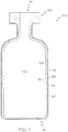
- FIG. 1 schematically depicts a cross section of a coated glass article, specifically a coated glass container 100.
- the coated glass container 100 comprises a glass body 102 and a low-friction coating 120.
- the glass body 102 has a glass container wall 104 extending between an exterior surface 108 (i.e., a first surface) and an interior surface 110 (i.e., a second surface).
- the interior surface 110 of the glass container wall 104 defines an interior volume 106 of the coated glass container 100.
- a low-friction coating 120 is positioned on at least a portion of the exterior surface 108 of the glass body 102. In some embodiments, the low-friction coating 120 may be positioned on substantially the entire exterior surface 108 of the glass body 102.
- the low-friction coating 120 has an outer surface 122 and a glass body contacting surface 124 at the interface of the glass body 102 and the low-friction coating 120.
- the low-friction coating 120 may be bonded to the glass body 102 at the exterior surface 108.
- the coated glass container 100 is a pharmaceutical package.
- the glass body 102 may be in the shape of a vial, ampoule, ampul, bottle, flask, phial, beaker, bucket, carafe, vat, syringe body, or the like.
- the coated glass container 100 may be used for containing any composition, and in one embodiment, may be used for containing a pharmaceutical composition.
- a pharmaceutical composition may include any chemical substance intended for use in the medical diagnosis, cure, treatment, or prevention of disease. Examples of pharmaceutical compositions include, but are not limited to, medicines, drugs, medications, medicaments, remedies, and the like.
- the pharmaceutical composition may be in the form of a liquid, solid, gel, suspension, powder, or the like.
- the low-friction coating 120 comprises a single layered structure sometimes referred to herein as a mono-layer structure.
- the low-friction coating 120 may have a substantially homogenous composition of a one or more polymers such as a halogenated polyimide siloxane.
- the low-friction coating 120 may comprise the halogenated polyimide siloxane in an amount of, for example, at least about 50 wt.%, at least about 60 wt.%, at least about 70 wt.%, at least about 80 wt.%, at least about 90 wt.%, at least about 95 wt.%, at least about 99 wt.%, or may consist essentially of the halogenated polyimide siloxane (e.g., at least about 99.5 wt.% of the low-friction coating 120 is a halogenated polyimide siloxane).
- a halogenated polyimide siloxane chemical composition and a coupling agent may be substantially mixed in a single layer to form the low-friction coating 120.
- the low-friction coating 120 may be a mixture of coupling agent and halogenated polyimide siloxane where the low-friction coating 120 comprises from, for example, 30 wt.% to 70 wt.% halogenated polyimide siloxane and 30 wt.% to 70 wt.% coupling agent.
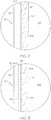
- the low-friction coating 120 comprises a bi-layered structure.
- FIG. 2 shows a cross section of a coated glass container 100, where the low-friction coating comprises a polymer layer 170 and a coupling agent layer 180.
- a polymer chemical composition such as a halogenated polyimide siloxane, may be contained in polymer layer 170 and a coupling agent may be contained in a coupling agent layer 180.
- the coupling agent layer 180 may be in direct contact with the exterior surface 108 of the glass container wall 104.
- the polymer layer 170 may be in direct contact with the coupling agent layer 180 and may form the outer surface 122 of the low-friction coating 120.
- the coupling agent layer 180 is bonded to the glass wall 104 and the polymer layer 170 is bonded to the coupling agent layer 180 at an interface 174.
- the polymer layer 170 may comprise the halogenated polyimide siloxane in an amount of, for example, at least about 50 wt.%, at least about 60 wt.%, at least about 70 wt.%, at least about 80 wt.%, at least about 90 wt.%, at least about 95 wt.%, at least about 99 wt.%, or may consist essentially of the halogenated polyimide siloxane (e.g., at least about 99.5 wt.% of the polymer layer 170 is a halogenated polyimide siloxane).
- the coupling agent layer 180 may comprise one or more coupling agents in an amount of, for example, at least about 50 wt.%, at least about 60 wt.%, at least about 70 wt.%, at least about 80 wt.%, at least about 90 wt.%, at least about 95 wt.%, at least about 99 wt.%, or may consist essentially of the one or more coupling agents (e.g., at least about 99.5 wt.% of the coupling agent layer 180 is a coupling agent).
- the polymer layer may be positioned over the coupling agent layer, meaning that the polymer layer 170 is in an outer layer relative to the coupling agent layer 180, and the glass wall 104.
- a first layer positioned "over" a second layer means that the first layer could be in direct contact with the second layer or separated from the second layer, such as with a third layer disposed between the first and second layers.
- the low-friction coating 120 applied to the glass body 102 may have a thickness of less than or equal to about 100 ⁇ m, less than or equal to about 10 ⁇ m, less than or equal to about 8 ⁇ m, less than or equal to about 6 ⁇ m, less than or equal to about 4 ⁇ m, less than or equal to about 3 ⁇ m, less than or equal to about 2 ⁇ m, or even less than or equal to about 1 ⁇ m.
- the thickness of the low-friction coating 120 may be less than or equal to about 800 nm, less than or equal to about 600 nm, less than or equal to about 400 nm 300 nm, less than or equal to about 200 nm, or even less than or equal to about 100 nm thick.
- the low-friction coating 120 may be less than about 90 nm thick, less than about 80 nm thick, less than about 70 nm thick, less than about 60 nm thick, less than about 50 nm, or even less than about 25 nm thick. In some embodiments, the low-friction coating 120 may not be of uniform thickness over the entirety of the glass body 102.
- the coated glass container 100 may have a thicker low-friction coating 120 in some areas, due to the process of contacting the glass body 102 with one or more coating solutions that form the low-friction coating 120.
- the low-friction coating 120 may have a non-uniform thickness. For example, the coating thickness may be varied over different regions of a coated glass container 100, which may promote protection in a selected region.
- each layer may have a thickness of less than about 100 ⁇ m, less than or equal to about 10 ⁇ m, less than or equal to about 8 ⁇ m, less than or equal to about 6 ⁇ m, less than or equal to about 4 ⁇ m, less than or equal to about 3 ⁇ m, less than or equal to about 2 ⁇ m, or even less than or equal to about 1 ⁇ m.
- the thickness of each layer may be less than or equal to about 0.5 ⁇ m, or even less than or equal to about 100 nm.
- each layer may be less than about 90 nm thick, less than about 80 nm thick, less than about 70 nm thick, less than about 60 nm thick, less than about 50 nm, or even less than about 25 nm thick.
- the low-friction coating 120 includes a polymer halogenated polyimide siloxane chemical composition.
- the halogenated polyimide siloxane may be formed from thermally stable halogenated polyimide siloxanes, such as halogenated polyimide siloxanes that do not substantially degrade at temperatures in the range of from 200 °C to 400 °C, including 250 °C, 300 °C, and 350 °C. These halogenated polyimide siloxanes may be applied with or without a coupling agent.
- halogenated polyimide siloxanes refer to polyimides which are halogenated and comprise a siloxane moiety.
- a “siloxane moiety” refers to a Si-O-Si bonded chemical group.
- One or more monomers of the halogenated polyimide siloxane may comprise such a siloxane moiety.
- a "halogenated” compound is a compound which includes one or more halogen molecules such as, but not limited to, fluorine, chlorine, bromine, and/or iodine, where the halogen may sometimes replace a hydrogen molecule in a hydrocarbon.
- the halogenated polyimide siloxanes may be formed from, for example, the reaction of one or more diamine monomer compositions with one or more dianhydride monomer compositions.
- Many polyimides are not stable in solution in a polyimide form, and are present in solution as polyamic acids, which are non-cylized polyimide precursors which are formed from diamine monomers and dianhydride monomers.
- the halogenated polyimide siloxanes of the present disclosure may be stable as fully imidized polyimide chemical species.
- the halogenated polyimide siloxanes may be deposited onto the glass articles in a fully imidized state and may not require a curing step to imidize, such as may be necessary for a polyamic acid that is deposited onto the glass article.
- the fully imidized halogenated polyimide siloxane may be cured, such as with a heat treatment about 300 °C for about 30 minutes or less.
- a curing may occur following the deposition of a coupling agent layer and a polymer layer, or following the deposition of a mixed polymer and coupling agent layer. Without being bound by theory, it is believed that a curing step may promote adhesion of the halogenated polyimide siloxane to the glass body, in both embodiments where a coupling agent is utilized and where a coupling agent is not utilized.
- polyamic acids must be cured to become imidized chemical species.
- Such curing may comprise heating the polyamic acid at 300 °C for about 30 minutes or less, or at a temperature higher than 300 °C, such as at least 320 °C, 340 °C, 360 °C, 380 °C, or 400 °C for a shorter time. It is believed, without being bound by theory, that the curing step imidizes a polyamic acid by reaction of carboxylic acid moieties and amide moieties to form a polyimide.
- halogenated polyimide siloxanes described herein may be soluble in a fully imidized form in a non-toxic and low boiling point solvent.
- non-toxic and low boiling point solvents may include acetates or ketones, such as, but not limited to, ethyl acetate, propyleneglycol methyl ether acetate, toluene, acetone, 2-butanone, and mixtures thereof.
- acetates or ketones such as, but not limited to, ethyl acetate, propyleneglycol methyl ether acetate, toluene, acetone, 2-butanone, and mixtures thereof.
- solvents such as acetates and ketones may be due to the combination of at least one amine terminated siloxane unit, at least one fluorinated aromatic dianhydride, and at least one aromatic fluorinated diamine in the polymer.
- the halogenated polyimide siloxane may be a copolymer comprising one or more of a first monomer comprising an amine terminated siloxane, a second monomer comprising a halogenated anhydride (such as a halogenated dianhydride), and a third monomer comprising a halogenated amine (such as a halogenated diamine).
- the halogenated polyimide siloxane may additionally comprise other monomers.
- the second monomer, the third monomer, or both may be fluorinated.
- the second monomer may comprise a fluorinated aromatic dianhydride
- the third monomer may comprise an aromatic fluorinated diamine.
- a monomer that is referred to as an "amine” may comprise 1, 2, 3, or even more amine moieties.
- an “anhydride” monomer may comprise 1, 2, 3, or even more anhydride moieties.
- polyimides may generally be formed from dianhydrides and diamines, the dianhydrides and diamines may comprise additional anhydride or amine moieties, respectively.
- the first monomer comprising an amine terminated siloxane may be 1,3-Bis(3-aminopropyl)-1,1,3,3-tetramethyl disiloxane, which is structurally depicted in Chemical Structure #1, below.
- 1,3-Bis(3-aminopropyl)-1,1,3,3-tetramethyl disiloxane may be referred to herein in an abbreviated form as "BADS".
- the second monomer comprising a halogenated dianhydride may be 4,4'-(Hexafluoroisopropylidene) diphthalic anhydride, which is structurally depicted in Chemical Structure #2, below.
- 4,4'-(Hexafluoroisopropylidene) diphthalic anhydride may be referred to herein in an abbreviated form as "6FDA".
- the third monomer comprising a halogenated diamine may be 2,2-Bis(4-aminophenyl) hexafluoropropane, which is structurally depicted in Chemical Structure #3, below.
- 2,2-Bis(4-aminophenyl) hexafluoropropane may be referred to herein in an abbreviated form as "6F".
- the halogenated polyimide siloxane may consist of the first monomer comprising an amine terminated siloxane, the second monomer comprising a halogenated dianhydride, and the third monomer comprising a halogenated diamine.
- the halogenated polyimide siloxane may consist of the three monomers listed in Chemical Structure #1, Chemical Structure #2, and Chemical Structure #3.
- Such a halogenated polyimide siloxane formed from Chemical Structure #1, Chemical Structure #2, and Chemical Structure #3 has the structure shown in Chemical Structure #4, below.
- Such a halogenated polyimide siloxane formed from Chemical Structure #1, Chemical Structure #2, and Chemical Structure #3 may be referred to herein in an abbreviated form as "Silimide-6F".
- 6FDA monomers are polymerized with 6F and BADS monomers, where the sum of the 6F and BADS monomers is about equal to the amount of 6FDA monomers present in the halogenated polyimide siloxane.
- the ratio of 6F monomers to BADS monomers is represented by the ratio of n to m.
- the ratio of 6F monomers to BADS monomers may be from about 9:1 to about 1:9, such as from about 8:2 to about 2:8, from about 7:3 to about 3:7, or from about 6:4 to about 4:6, such as about 1:1.
- the ratio of 6F monomers to BADS monomers may be from about 9:1 to about 6:1, or from about 8:1 to about 7:1, such as about 3:1. Additionally, it should be understood that the above recited ratios of 6F to BADS may apply generally as ratios for any amine terminated siloxane monomers to halogenated diamine monomers that are utilized to form halogenated polyimide siloxanes.
- the ratio of halogenated diamine monomers to amine terminated siloxane monomers is high, such as greater than about 9:1, then the resistance to discoloration (especially yellowing) at high temperature is acceptable, the glass transition temperature of the halogenated polyimide siloxane is high, but the adhesion of the coating may be degraded.
- the ratio is low, such as less than about 1:9, the halogenated polyimide siloxane may exhibit good adhesion on glass but may thermally degrade at lower temperatures, have a lower glass transition temperature, and may have visible discoloration (yellowing) when cured or exposed to thermal treatments such as depyrogenation.
- the halogenated polyimide siloxanes described herein may have a glass transition temperature of from about 50 °C to about 300 °C.
- a polyimide formed from 6FDA and 6F in a 1:1 molar ratio may have a glass transition temperature of about 300 °C
- a polyimide formed from 6FDA and BADS in a 1:1 molar ratio may have a glass transition temperature of about 50 °C.
- it is believed that a polyimide formed from 6FDA, BADS, and 6F will have a glass transition temperature that is between about 50 °C and about 300 °C, where the glass transition temperature is a function of the ratio of BADS to 6F.
- halogenated diamine In additional to the amine terminated siloxane, halogenated diamine, and halogenated dianhydride, other monomers may be present in the halogenated polyimide siloxane.
- monomers that are not amine terminated siloxanes, halogenated diamine, or halogenated dianhydrides may make up as much as 5% of monomers, 10% of monomers, 20% of monomers, or even at least about 30% of monomers of the halogenated polyimide siloxane.
- additional monomers may be incorporated for enhanced solubility in solvents.
- the halogenated polyimide siloxane may comprise halogenated dianhydride monomers in an amount of at least about 20% of the total monomers, at least about 30% of the total monomers, at least about 40% of the total monomers, at least about 45% of the total monomers, or even 50% the total of monomers.
- the halogenated polyimide siloxane may comprise halogenated diamine monomers in an amount of at least about 10% of the total monomers, at least about 15% of the total monomers, at least about 20% of the total monomers, at least about 23% of the total monomers, or even 25% the total of monomers.
- the halogenated polyimide siloxane may comprise amine terminated siloxane monomers in an amount of at least about 10% of the total monomers, at least about 15% of the total monomers, at least about 20% of the total monomers, at least about 23% of the total monomers, or even 25% the total of monomers.
- the percentages of a specific monomer in a polyimide refers to a molar ratio of the number of monomer units of a particular monomer divided by the total number of monomers in the polyimide chain.
- the halogenated polyimide siloxane may include a monomer which includes the joined double benzene moiety depicted in Chemical Structure #5.
- "A” may represent -C(CH 3 ) 2 -, -SO 2 -, -S-, or -O-, and "a” represents 0 or 1 (0 meaning the benzenes are directly connected without an "A" group).
- the halogenated polyimide siloxane may be a random copolymer.
- the halogenated polyimide siloxanes described herein may have a number average molar mass (M n ) of about 19 Da, such as from about 18 Da to about 20 Da, from about 17 Da to about 21 Da, from about 16 Da to about 22 Da, or from about 15 Da to about 23 Da.
- M n number average molar mass
- the Silimide-6F polyimide of Chemical Structure #4 may have a M n equal to about 19 Da when m:n is about 3:1 (referred to herein as "Silimide-6F 25/75").
- the halogenated polyimide siloxanes described herein may have a weight average molar mass (M w ) of about 40 Da, such as from about 39 Da to about 41 Da, from about 38 Da to about 42 Da, from about 36 Da to about 44 Da, or from about 30 Da to about 50 Da.
- M w weight average molar mass
- the Silimide-6F polyimide of Chemical Structure #4 may have a M w equal to about 19 Da when m:n is about 3:1.
- the halogenated polyimide siloxanes described herein may have a polydispersity index of about 2.15, such as from about 2.0 to about 2.3, from about 1.8 to about 2.5, or from about 1.5 to about 2.8.
- the Silimide-6F polyimide of Chemical Structure #4 may have a polydispersity index of about 2.15 when m:n is about 3:1.
- the low-friction coating 120 comprises a coupling agent.
- the coupling agent may improve the adherence or bonding of the halogenated polyimide siloxanes to the glass body 102, and is generally disposed between the glass body 102 and the halogenated polyimide siloxanes or mixed with the halogenated polyimide siloxanes.
- Adhesion refers to the strength of adherence or bonding of the low friction coating prior to and following a treatment applied to the coated glass container, such as a thermal treatment. Thermal treatments include, without limitation, autoclaving, depyrogenation, lyophilization, or the like. It should be understood that the curing processes described herein are separate from the heating treatments described herein, such as those heating treatments similar or identical to processes in the pharmaceutical packaging industry, such as depyrogenation or the heating treatments used to define thermal stability, as described herein.
- the coupling agent may comprise at least one silane chemical composition.
- a "silane" chemical composition is any chemical composition comprising a silane moiety, including functional organosilanes, as well as silanols formed from silanes in aqueous solutions.
- the silane chemical compositions of the coupling agent may be aromatic or aliphatic.
- the at least one silane chemical composition may comprise an amine moiety, such as a primary amine moiety or a secondary amine moiety.
- the coupling agent may comprise hydrolysates and/or oligomers of such silanes, such as one or more silsesquioxane chemical compositions that are formed from the one or more silane chemical compositions.
- the silsesquioxane chemical compositions may comprise a full cage structure, partial cage structure, or no cage structure.
- the coupling agent may comprise any number of different chemical compositions, such as one chemical composition, two different chemical compositions, or more than two different chemical compositions including oligomers formed from more than one monomeric chemical composition.
- the coupling agent may comprise at least one of (1) a first silane chemical composition, hydrolysate thereof, or oligomer thereof, and (2) a chemical composition formed from the oligomerization of at least the first silane chemical composition and a second silane chemical composition.
- the coupling agent comprises a first and second silane.
- a "first" silane chemical composition and a "second" silane chemical composition are silanes having different chemical compositions.
- the first silane chemical composition may be an aromatic or an aliphatic chemical composition, may optionally comprise an amine moiety, and may optionally be an alkoxysilane.
- the second silane chemical composition may be an aromatic or an aliphatic chemical composition, may optionally comprise an amine moiety, and may optionally be an alkoxysilane.
- the coupling agent may comprise a silane chemical composition, hydrolysate thereof, or oligomer thereof.
- the coupling agent may comprise at least one of (1) a mixture of the first silane chemical composition and a second silane chemical composition, and (2) a chemical composition formed from the oligomerization of at least the first silane chemical composition and the second silane chemical composition.
- the first silane chemical composition, second silane chemical composition, or both may be aromatic chemical compositions.
- an aromatic chemical composition contains one or more six-carbon rings characteristic of the benzene series and related organic moieties.
- the aromatic silane chemical composition may be an alkoxysilane such as, but not limited to, a dialkoxysilane chemical composition, hydrolysate thereof, or oligomer thereof, or a trialkoxysilane chemical composition, hydrolysate thereof, or oligomer thereof.
- the aromatic silane may comprise an amine moiety, and may be an alkoxysilane comprising an amine moiety.
- the aromatic silane chemical composition may be an aromatic alkoxysilane chemical composition, an aromatic acyloxysilane chemical composition, an aromatic halogen silane chemical composition, or an aromatic aminosilane chemical composition.
- the aromatic silane chemical composition may be selected from the group consisting of aminophenyl, 3-(m-aminophenoxy) propyl, N-phenylaminopropyl, or (chloromethy) phenyl substituted alkoxy, acyloxy, halogen, or amino silanes.
- the aromatic alkoxysilane may be, but is not limited to, aminophenyltrimethoxy silane (sometimes referred to herein as "APhTMS"), aminophenyldimethoxy silane, aminophenyltriethoxy silane, aminophenyldiethoxy silane, 3-(m-aminophenoxy) propyltrimethoxy silane, 3-(m-aminophenoxy) propyldimethoxy silane, 3-(m-aminophenoxy) propyltriethoxy silane, 3-(m-aminophenoxy) propyldiethoxy silane, N-phenylaminopropyltrimethoxysilane, N-phenylaminopropyldimethoxysilane, N-phenylaminopropyltriethoxysilane, N-phenylaminopropyldiethoxysilane, hydrolysates thereof, or oligomerized chemical composition thereof.
- the aromatic silane chemical composition is, but is not limited
- the first silane chemical composition, second silane chemical composition, or both may be aliphatic chemical compositions.
- an aliphatic chemical composition is non-aromatic, such as a chemical composition having an open chain structure, such as, but not limited to, alkanes, alkenes, and alkynes.
- the coupling agent may comprise a chemical composition that is an alkoxysilane and may be an aliphatic alkoxysilane such as, but not limited to, a dialkoxysilane chemical composition, a hydrolysate thereof, or an oligomer thereof, or a trialkoxysilane chemical composition, a hydrolysate thereof, or an oligomer thereof.
- the aliphatic silane may comprise an amine moiety, and may be an alkoxysilane comprising an amine moiety, such as an aminoalkyltrialkoxysilane.
- an aliphatic silane chemical composition may be selected from the group consisting of 3-aminopropyl, N-(2-aminoethyl)-3-aminopropyl, vinyl, methyl, N-phenylaminopropyl, (N-phenylamino)methyl, N-(2-Vinylbenzylaminoethyl)-3-aminopropyl substituted alkoxy, acyloxy, halogen, or amino silanes, hydrolysates thereof, or oligomers thereof.
- Aminoalkyltrialkoxysilanes include, but are not limited to, 3-aminopropyltrimethoxy silane (sometimes referred to herein as "GAPS"), 3-aminopropyldimethoxy silane, 3-aminopropyltriethoxy silane, 3-aminopropyldiethoxy silane, N-(2-aminoethyl)-3-aminopropyltrimethoxysilane, N-(2-aminoethyl)-3-aminopropyldimethoxysilane, N-(2-aminoethyl)-3-aminopropyltriethoxysilane, N-(2-aminoethyl)-3-aminopropyldiethoxysilane, hydrolysates thereof, and oligomerized chemical composition thereof.
- GAPS 3-aminopropyltrimethoxy silane
- 3-aminopropyltriethoxy silane sometimes referred to herein
- the aliphatic alkoxysilane chemical composition may not contain an amine moiety, such as an alkyltrialkoxysilane or alkylbialkoxysilane.
- alkyltrialkoxysilanes or alkylbialkoxysilanes include, but are not limited to, vinyltrimethoxy silane, vinyldimethoxy silane, vinyltriethoxy silane, vinyldiethoxy silane, methyltrimethoxysilane, methyltdimethoxysilane, methyltriethoxysilane, methyldiethoxysilane, hydrolysates thereof, or oligomerized chemical composition thereof.
- the aliphatic silane chemical composition is 3-aminopropyltrimethoxy silane.
- amino bis silanes such as, but not limited to bis((3-triethoxysilyl)propyl)amine or bis((3-trimethoxysilyl)propyl)amine.
- the coupling agent may comprise a urea-functionalized silane and may be devoid of amino groups and aromatic groups. Without being bound by theory, it is believed that such urea-functionalized silane layers do not undergo any discoloration and thus prevent yellowing of the protective coating when exposed to thermal treatments such as depyrogenation. Additionally, urea-functionalized silane coupling agents may be less expensive than amino-functionalized silanes and aliphatic silanes may be less expensive than aromatic silanes. Thus, an aliphatic urea-functionalized silane may be desirable over some amino-functionalized aromatic silanes.
- urea-functionalized silanes include 1-[3-(Trimethoxysilyl)propyl]urea, 1-(3-(Triethoxysilyl)propyl)urea, Bis(ureido)silane, and ureas prepared from isocyanates or amino silanes.
- the coupling agent may comprise a chemical composition that is an aminoalkylsilsesquioxane.
- the coupling agent comprises aminopropylsilsesquioxane (APS) oligomer (commercially available as an aqueous solution from Gelest).
- the aromatic silane chemical composition is a chlorosilane chemical composition.
- the coupling agent may comprise chemical composition that are hydrolyzed analogs of aminoalkoxysilanes such as, but not limited to, (3-Aminopropyl)silantriol, N-(2-Aminoethyl)-3-aminopropyl-silantriol and/or mixtures thereof.
- the coupling agent may be an inorganic material, such as metal and/or a ceramic film.
- suitable inorganic materials used as the coupling agent include titanates, zirconates, tin, titanium, and/or oxides thereof.
- the low-friction coating 120 may be applied in a single deposition step (in cases where the low-friction coating 120 comprises a single layer as in FIG. 2 ) or may be applied in a multi-stage process, wherein the glass body 102 is contacted with the coupling agent solution to form the coupling agent layer 180 (as described above), and optionally dried, and then contacted with a polymer chemical composition solution, such as a halogenated polyimide siloxane in solution, such as by a submersion process, or alternatively, the polymer layer 170 may be applied by a spray or other suitable means, and optionally dried.
- a polymer chemical composition solution such as a halogenated polyimide siloxane in solution
- the glass articles, such as glass containers, to which the low-friction coating 120 may be applied may be formed from a variety of different glass compositions.
- the specific composition of the glass article may be selected according to the specific application such that the glass has a desired set of physical properties.
- the glass containers may be formed from a glass composition which has a coefficient of thermal expansion in the range from about 25x10 -7 /°C to 80x10 -7 /°C.
- the glass body 102 is formed from alkali aluminosilicate glass compositions which are amenable to strengthening by ion exchange.
- Such compositions generally include a combination of SiO 2 , Al 2 O 3 , at least one alkaline earth oxide, and one or more alkali oxides, such as Na 2 O and/or K 2 O.
- the glass composition may be free from boron and compounds containing boron.
- the glass compositions may further comprise minor amounts of one or more additional oxides such as, for example, SnO 2 , ZrO 2 , ZnO, TiO 2 , As 2 O 3 , or the like. These components may be added as fining agents and/or to further enhance the chemical durability of the glass composition.
- the glass surface may comprise a metal oxide coating comprising SnO 2 , ZrO 2 , ZnO, TiO 2 , As 2 O 3 , or the like.
- the glass body 102 is strengthened such as by ion-exchange strengthening, herein referred to as "ion-exchanged glass".
- the glass body 102 may have a compressive stress of greater than or equal to about 300 MPa or even greater than or equal to about 350 MPa.
- the compressive stress may be in a range from about 300 MPa to about 900 MPa.
- the compressive stress in the glass may be less than 300 MPa or greater than 900 MPa.
- the glass body 102 may have a depth of layer greater than or equal to 20 ⁇ m.
- the depth of layer may be greater than 50 ⁇ m or even greater than or equal to 75 ⁇ m. In still other embodiments, the depth of the layer may be up to or greater than 100 ⁇ m.
- the ion-exchange strengthening may be performed in a molten salt bath maintained at temperatures from about 350 °C to about 500 °C. To achieve the desired compressive stress, the glass container (uncoated) may be immersed in the salt bath for less than about 30 hours or even less than about 20 hours. For example, in one embodiment the glass container is immersed in a 100% KNO 3 salt bath at 450 °C for about 8 hours.
- the glass body 102 may be formed from an ion exchangeable glass composition described in pending U.S. Patent Application Serial No. 13/660894 filed October 25, 2012 and entitled "Glass Compositions with Improved Chemical and Mechanical Durability” assigned to Corning, Incorporated.
- coated glass containers 100 described herein may be formed from other glass compositions including, without limitation, ion-exchangeable glass compositions and non-ion exchangeable glass compositions.
- the glass container may be formed from Type 1B glass compositions such as, for example, Schott Type 1B aluminosilicate glass.
- the glass article may be formed from a glass composition which meets the criteria for pharmaceutical glasses described by regulatory agencies such as the USP (United States Pharmacopoeia), the EP (European Pharmacopeia), and the JP (Japanese Pharmacopeia) based on their hydrolytic resistance.
- USP 660 and EP 7 borosilicate glasses meet the Type I criteria and are routinely used for parenteral packaging. Examples of borosilicate glass include, but not limited to Corning® Pyrex® 7740, 7800 and Wheaton 180, 200, and 400, Schott Duran, Schott Fiolax, KIMAX® N-51A, Gerrescheimer GX-51 Flint and others.
- Soda-lime glass meets the Type III criteria and is acceptable in packaging of dry powders which are subsequently dissolved to make solutions or buffers.
- Type III glasses are also suitable for packaging liquid formulations that prove to be insensitive to alkali.
- Examples of Type III soda lime glass include Wheaton 800 and 900.
- De-alkalized soda-lime glasses have higher levels of sodium hydroxide and calcium oxide and meet the Type II criteria. These glasses are less resistant to leaching than Type I glasses but more resistant than Type III glasses.
- Type II glasses can be used for products that remain below a pH of 7 for their shelf life. Examples include ammonium sulfate treated soda lime glasses.
- These pharmaceutical glasses have varied chemical compositions and have a coefficient of linear thermal expansion (CTE) in the range of 20-85 x 10 -7 °C -1 .
- the glass body 102 of the coated glass containers 100 may take on a variety of different forms.
- the glass bodies described herein may be used to form coated glass containers 100 such as vials, ampoules, cartridges, syringe bodies and/or any other glass container for storing pharmaceutical compositions.
- the ability to chemically strengthen the glass containers prior to coating can be utilized to further improve the mechanical durability of the glass containers.
- the glass containers may be ion exchange strengthened prior to application of the low-friction coating.
- other strengthening methods such as heat tempering, flame polishing, and laminating, as described in U.S. Patent No. 7,201,965 , could be used to strengthen the glass before coating.
- Various properties of the coated glass containers may be measured when the coated glass containers are in an as-coated condition (i.e., following application of the coating without any additional treatments other than curing if applicable) or following one or more processing treatments, such as those similar or identical to treatments performed on a pharmaceutical filling line, including, without limitation, washing, lyophilization, depyrogenation, autoclaving, or the like.
- Depyrogentation is a process wherein pyrogens are removed from a substance.
- Depyrogenation of glass articles can be performed by a thermal treatment applied to a sample in which the sample is heated to an elevated temperature for a period of time.
- depyrogenation may include heating a glass container to a temperature of between about 250 °C and about 380 °C for a time period from about 30 seconds to about 72 hours, including, without limitation, 20 minutes, 30 minutes 40 minutes, 1 hour, 2 hours, 4 hours, 8 hours, 12 hours, 24 hours, 48 hours, and 72 hours.
- the glass container is cooled to room temperature.
- One conventional depyrogenation condition commonly employed in the pharmaceutical industry is thermal treatment at a temperature of about 250 °C for about 30 minutes. However, it is contemplated that the time of thermal treatment may be reduced if higher temperatures are utilized.
- the coated glass containers, as described herein may be exposed to elevated temperatures for a period of time. The elevated temperatures and time periods of heating described herein may or may not be sufficient to depyrogenate a glass container. However, it should be understood that some of the temperatures and times of heating described herein are sufficient to dehydrogenate a coated glass container, such as the coated glass containers described herein.
- the coated glass containers may be exposed to temperatures of about 260 °C, about 270 °C, about 280 °C, about 290 °C, about 300 °C, about 310 °C, about 320 °C, about 330 °C, about 340 °C, about 350 °C, about 360 °C, about 370 °C, about 380 °C, about 390 °C, or about 400 °C, for a period of time of 30 minutes.
- lyophilization conditions i.e., freeze drying refer to a process in which a sample is filled with a liquid that contains protein and then frozen at -100 °C, followed by water sublimation for 20 hours at -15 °C under vacuum.
- autoclave conditions refer to steam purging a sample for 10 minutes at 100 °C, followed by a 20 minute dwelling period wherein the sample is exposed to a 121°C environment, followed by 30 minutes of heat treatment at 121°C.
- the coefficient of friction ( ⁇ ) of the portion of the coated glass container with the low-friction coating may have a lower coefficient of friction than a surface of an uncoated glass container formed from a same glass composition.
- a coefficient of friction ( ⁇ ) is a quantitative measurement of the friction between two surfaces and is a function of the mechanical and chemical properties of the first and second surfaces, including surface roughness, as well as environmental conditions such as, but not limited to, temperature and humidity.
- a coefficient of friction measurement for coated glass container 100 is reported as the coefficient of friction between the outer surface of a first glass container (having an outer diameter of between about 16.00 mm and about 17.00 mm) and the outer surface of second glass container which is identical to the first glass container, wherein the first and second glass containers have the same body and the same coating composition (when applied) and have been exposed to the same environments prior to fabrication, during fabrication, and after fabrication.
- the coefficient of friction refers to the maximum coefficient of friction measured with a normal load of 30 N measured on a vial-on-vial testing jig, as described herein.
- a coated glass container which exhibits a maximum coefficient of friction at a specific applied load will also exhibit the same or better (i.e., lower) maximum coefficient of friction at a lesser load. For example, if a coated glass container exhibits a maximum coefficient of friction of 0.5 or lower under an applied load of 50 N, the coated glass container will also exhibit a maximum coefficient of friction of 0.5 or lower under an applied load of 25 N.
- the coefficient of friction of the glass containers is measured with a vial-on-vial testing jig.
- the testing jig 200 is schematically depicted in FIG. L.
- the same apparatus may also be used to measure the frictive force between two glass containers positioned in the jig.
- the vial-on-vial testing jig 200 comprises a first clamp 212 and a second clamp 222 arranged in a cross configuration.
- the first clamp 212 comprises a first securing arm 214 attached to a first base 216.
- the first securing arm 214 attaches to the first glass container 210 and holds the first glass container 210 stationary relative to the first clamp 212.
- the second clamp 222 comprises a second securing arm 224 attached to a second base 226.
- the second securing arm 224 attaches to the second glass container 220 and holds it stationary relative to the second clamp 222.
- the first glass container 210 is positioned on the first clamp 212 and the second glass container 220 is positioned of the second clamp 222 such that the long axis of the first glass container 210 and the long axis of the second glass container 220 are positioned at about a 90° angle relative to one another and on a horizontal plane defined by the x-y axis.
- a first glass container 210 is positioned in contact with the second glass container 220 at a contact point 230.
- a normal force is applied in a direction orthogonal to the horizontal plane defined by the x-y axis.
- the normal force may be applied by a static weight or other force applied to the second clamp 222 upon a stationary first clamp 212.
- a weight may be positioned on the second base 226 and the first base 216 may be placed on a stable surface, thus inducing a measurable force between the first glass container 210 and the second glass container 220 at the contact point 230.
- the force may be applied with a mechanical apparatus, such as a UMT (universal mechanical tester) machine.
- the first clamp 212 or second clamp 222 may be moved relative to the other in a direction which is at a 45° angle with the long axis of the first glass container 210 and the second glass container 220.
- the first clamp 212 may be held stationary and the second clamp 222 may be moved such that the second glass container 220 moves across the first glass container 210 in the direction of the x-axis.
- R. L. De Rosa et al. in "Scratch Resistant Polyimide Coatings for Alumino Silicate Glass surfaces” in The Journal of Adhesion, 78: 113-127, 2002 .
- the force required to move the second clamp 222 and the normal force applied to first and second glass containers 210, 220 are measured with load cells and the coefficient of friction is calculated as the quotient of the frictive force and the normal force.
- the jig is operated in an environment of 25 °C and 50% relative humidity.
- the portion of the coated glass container with the low-friction coating has a coefficient of friction of less than or equal to about 0.7 relative to a like-coated glass container, as determined with the vial-on-vial jig described above. In other embodiments, the coefficient of friction may be less than or equal to about 0.6, or even less than or equal to about 0.5. In some embodiments, the portion of the coated glass container with the low-friction coating has a coefficient of friction of less than or equal to about 0.4 or even less than or equal to about 0.3. Coated glass containers with coefficients of friction less than or equal to about 0.7 generally exhibit improved resistance to frictive damage and, as a result, have improved mechanical properties. For example, conventional glass containers (without a low-friction coating) may have a coefficient of friction of greater than 0.7.
- the coefficient of friction of the portion of the coated glass container with the low-friction coating is at least 20% less than a coefficient of friction of a surface of an uncoated glass container formed from a same glass composition.
- the coefficient of friction of the portion of the coated glass container with the low-friction coating may be at least 20% less, at least 25% less, at least 30% less, at least 40% less, or even at least 50% less than a coefficient of friction of a surface of an uncoated glass container formed from a same glass composition.
- the portion of the coated glass container with the low-friction coating may have a coefficient of friction of less than or equal to about 0.7 after exposure to a temperature of about 260 °C, about 270 °C, about 280 °C, about 290 °C, about 300 °C, about 310 °C, about 320 °C, about 330 °C, about 340 °C, about 350 °C, about 360 °C, about 370 °C, about 380 °C, about 390 °C, or about 400 °C, for a period of time of 30 minutes.
- the portion of the coated glass container with the low-friction coating may have a coefficient of friction of less than or equal to about 0.7, (i.e., less than or equal to about 0.6, less than or equal to about 0.5, less than or equal to about 0.4, or even less than or equal to about 0.3) after exposure to a temperature of about 260 °C, about 270 °C, about 280 °C, about 290 °C, about 300 °C, about 310 °C, about 320 °C, about 330 °C, about 340 °C, about 350 °C, about 360 °C, about 370 °C, about 380 °C, about 390 °C, or about 400 °C, for a period of time of 30 minutes.
- the coefficient of friction of the portion of the coated glass container with the low-friction coating may not increase by more than about 30% after exposure to a temperature of about 260 °C for 30 minutes. In other embodiments, coefficient of friction of the portion of the coated glass container with the low-friction coating may not increase by more than about 30% (i.e., about 25%, about 20%, about 15%, or event about 10%) after exposure to a temperature of about 260 °C, about 270 °C, about 280 °C, about 290 °C, about 300 °C, about 310 °C, about 320 °C, about 330 °C, about 340 °C, about 350 °C, about 360 °C, about 370 °C, about 380 °C, about 390 °C, or about 400 °C, for a period of time of 30 minutes.
- coefficient of friction of the portion of the coated glass container with the low-friction coating may not increase by more than about 0.5 (i.e., about 0.45, about .04, about 0.35, about 0.3, about 0.25, about 0.2, about 0.15, about 0.1, or event about 0.5) after exposure to a temperature of about 260 °C, about 270 °C, about 280 °C, about 290 °C, about 300 °C, about 310 °C, about 320 °C, about 330 °C, about 340 °C, about 350 °C, about 360 °C, about 370 °C, about 380 °C, about 390 °C, or about 400 °C, for a period of time of 30 minutes.
- the coefficient of friction of the portion of the coated glass container with the low-friction coating may not increase at all after exposure to a temperature of about 260 °C, about 270 °C, about 280 °C, about 290 °C, about 300 °C, about 310 °C, about 320 °C, about 330 °C, about 340 °C, about 350 °C, about 360 °C, about 370 °C, about 380 °C, about 390 °C, or about 400 °C, for a period of time of 30 minutes.
- the portion of the coated glass container with the low-friction coating may have a coefficient of friction of less than or equal to about 0.7 after being submerged in a water bath at a temperature of about 70 °C for 10 minutes. In other embodiments, the portion of the coated glass container with the low-friction coating may have a coefficient of friction of less than or equal to about 0.7, (i.e., less than or equal to about 0.6, less than or equal to about 0.5, less than or equal to about 0.4, or even less than or equal to about 0.3) after being submerged in a water bath at a temperature of about 70 °C for 5 minutes, 10 minutes, 20 minutes, 30 minutes, 40 minutes, 50 minutes, or even 1 hour.
- the coefficient of friction of the portion of the coated glass container with the low-friction coating may not increase by more than about 30% after being submerged in a water bath at a temperature of about 70 °C for 10 minutes. In other embodiments, coefficient of friction of the portion of the coated glass container with the low-friction coating may not increase by more than about 30% (i.e., about 25%, about 20%, about 15%, or event about 10%) after being submerged in a water bath at a temperature of about 70 °C for 5 minutes, 10 minutes, 20 minutes, 30 minutes, 40 minutes, 50 minutes, or even 1 hour.
- the coefficient of friction of the portion of the coated glass container with the low-friction coating may not increase at all after being submerged in a water bath at a temperature of about 70 °C for 5 minutes, 10 minutes, 20 minutes, 30 minutes, 40 minutes, 50 minutes, or even 1 hour.
- the portion of the coated glass container with the low-friction coating may have a coefficient of friction of less than or equal to about 0.7 after exposure to lyophilization conditions. In other embodiments, the portion of the coated glass container with the low-friction coating may have a coefficient of friction of less than or equal to about 0.7, (i.e., less than or equal to about 0.6, less than or equal to about 0.5, less than or equal to about 0.4, or even less than or equal to about 0.3) after exposure to lyophilization conditions. In some embodiments, the coefficient of friction of the portion of the coated glass container with the low-friction coating may not increase by more than about 30% after exposure to lyophilization conditions.
- coefficient of friction of the portion of the coated glass container with the low-friction coating may not increase by more than about 30% (i.e., about 25%, about 20%, about 15%, or event about 10%) after exposure to lyophilization conditions. In some embodiments, the coefficient of friction of the portion of the coated glass container with the low-friction coating may not increase at all after exposure to lyophilization conditions.
- the portion of the coated glass container with the low-friction coating may have a coefficient of friction of less than or equal to about 0.7 after exposure to autoclave conditions. In other embodiments, the portion of the coated glass container with the low-friction coating may have a coefficient of friction of less than or equal to about 0.7, (i.e., less than or equal to about 0.6, less than or equal to about 0.5, less than or equal to about 0.4, or even less than or equal to about 0.3) after exposure to autoclave conditions. In some embodiments, the coefficient of friction of the portion of the coated glass container with the low-friction coating may not increase by more than about 30% after exposure to autoclave conditions.
- coefficient of friction of the portion of the coated glass container with the low-friction coating may not increase by more than about 30% (i.e., about 25%, about 20%, about 15%, or event about 10%) after exposure to autoclave conditions. In some embodiments, the coefficient of friction of the portion of the coated glass container with the low-friction coating may not increase at all after exposure to autoclave conditions.
- the coated glass containers described herein have a horizontal compression strength.
- the horizontal compression strength is measured by positioning the coated glass container 100 horizontally between two parallel platens which are oriented in parallel to the long axis of the glass container. A mechanical load is then applied to the coated glass container 100 with the platens in the direction perpendicular to the long axis of the glass container.
- the load rate for vial compression is 0.5 in/min, meaning that the platens move towards each other at a rate of 0.5 in/min.
- the horizontal compression strength is measured at 25 °C and 50% relative humidity.
- a measurement of the horizontal compression strength can be given as a failure probability at a selected normal compression load. As used herein, failure occurs when the glass container ruptures under a horizontal compression in least 50% of samples.
- a coated glass container may have a horizontal compression strength at least 10%, 20%, or 30% greater than an uncoated vial.
- the horizontal compression strength measurement may also be performed on an abraded glass container.
- operation of the testing jig 200 may create damage on the coated glass container outer surface 122, such as a surface scratch or abrasion that weakens the strength of the coated glass container 100.
- the glass container is then subjected to the horizontal compression procedure described above, wherein the container is placed between two platens with the scratch pointing outward parallel to the platens.
- the scratch can be characterized by the selected normal pressure applied by a vial-on-vial jig and the scratch length.
- scratches for abraded glass containers for the horizontal compression procedure are characterized by a scratch length of 20 mm created by a normal load of 30 N.
- the coated glass containers can be evaluated for horizontal compression strength following a heat treatment.
- the heat treatment may be exposure to a temperature of about 260 °C, about 270 °C, about 280 °C, about 290 °C, about 300 °C, about 310 °C, about 320 °C, about 330 °C, about 340 °C, about 350 °C, about 360 °C, about 370 °C, about 380 °C, about 390 °C, or about 400 °C, for a period of time of 30 minutes.
- the horizontal compression strength of the coated glass container is not reduced by more than about 20%, 30%, or even 40% after being exposed to a heat treatment, such as those described above, and then being abraded, as described above. In one embodiment, the horizontal compression strength of the coated glass container is not reduced by more than about 20% after being exposed to a heat treatment of about 260 °C, about 270 °C, about 280 °C, about 290 °C, about 300 °C, about 310 °C, about 320 °C, about 330 °C, about 340 °C, about 350 °C, about 360 °C, about 370 °C, about 380 °C, about 390 °C, or about 400 °C, for a period of time of 30 minutes, and then being abraded.
- the coated glass articles described herein may be thermally stable after heating to a temperature of at least 260 °C for a time period of 30 minutes.
- thermally stable means that the low friction coating applied to the glass article remains substantially intact on the surface of the glass article after exposure to the elevated temperatures such that, after exposure, the mechanical properties of the coated glass article, specifically the coefficient of friction and the horizontal compression strength, are only minimally affected, if at all. This indicates that the low friction coating remains adhered to the surface of the glass following elevated temperature exposure and continues to protect the glass article from mechanical insults such as abrasions, impacts and the like.
- a coated glass article is considered to be thermally stable if the coated glass article meets both a coefficient of friction standard and a horizontal compression strength standard after heating to the specified temperature and remaining at that temperature for the specified time.
- the coefficient of friction standard is met, the coefficient of friction of a first coated glass article is determined in as-received condition (i.e., prior to any thermal exposure) using the testing jig depicted in FIG. 4 and a 30 N applied load.
- a second coated glass article i.e., a glass article having the same glass composition and the same coating composition as the first coated glass article
- the coefficient of friction of the second glass article is determined using the testing jig depicted in FIG. L to abrade the coated glass article with a 30 N applied load resulting in an abraded (i.e., a "scratch") having a length of approximately 20 mm. If the coefficient of friction of the second coated glass article is less than 0.7 and the surface of the glass of the second glass article in the abraded area does not have any observable damage, then the coefficient of friction standard is met for purposes of determining the thermal stability of the low friction coating.
- observation damage means that the surface of the glass in the abraded area of the glass article contains less than six glass checks per 0.5 cm of length of the abraded area when observed with a Nomarski or differential interference contrast (DIC) spectroscopy microscope at a magnification of 100X with LED or halogen light sources.
- DIC differential interference contrast
- a first coated glass article is abraded in the testing jig depicted in FIG. L under a 30 N load to form a 20 mm scratch.
- the first coated glass article is then subjected to a horizontal compression test, as described herein, and the retained strength of the first coated glass article is determined.
- a second coated glass article i.e., a glass article having the same glass composition and the same coating composition as the first coated glass article
- the second coated glass article is abraded in the testing jig depicted in FIG. L under a 30 N load.
- the second coated glass article is then subjected to a horizontal compression test, as described herein, and the retained strength of the second coated glass article is determined. If the retained strength of the second coated glass article does not decrease by more than about 20% relative to the first coated glass article then the horizontal compression strength standard is met for purposes of determining the thermal stability of the low friction coating.
- the coated glass containers are considered to be thermally stable if the coefficient of friction standard and the horizontal compression strength standard are met after exposing the coated glass containers to a temperature of at least about 260 °C for a time period of about 30 minutes (i.e., the coated glass containers are thermally stable at a temperature of at least about 260 °C for a time period of about 30 minutes).
- the thermal stability may also be assessed at temperatures from about 260 °C up to about 400 °C.
- the coated glass containers will be considered to be thermally stable if the standards are met at a temperature of at least about 270 °C or even about 280 °C for a time period of about 30 minutes.
- the coated glass containers will be considered to be thermally stable if the standards are met at a temperature of at least about 290 °C or even about 300 °C for a time period of about 30 minutes. In further embodiments, the coated glass containers will be considered to be thermally stable if the standards are met at a temperature of at least about 310 °C or even about 320 °C for a time period of about 30 minutes. In still other embodiments, the coated glass containers will be considered to be thermally stable if the standards are met at a temperature of at least about 330 °C or even about 340 °C for a time period of about 30 minutes.
- the coated glass containers will be considered to be thermally stable if the standards are met at a temperature of at least about 350 °C or even about 360 °C for a time period of about 30 minutes. In some other embodiments, the coated glass containers will be considered to be thermally stable if the standards are met at a temperature of at least about 370 °C or even about 380 °C for a time period of about 30 minutes. In still other embodiments, the coated glass containers will be considered to be thermally stable if the standards are met at a temperature of at least about 390 °C or even about 400 °C for a time period of about 30 minutes.
- the coated glass containers disclosed herein may also be thermally stable over a range of temperatures, meaning that the coated glass containers are thermally stable by meeting the coefficient of friction standard and horizontal compression strength standard at each temperature in the range.
- the coated, glass containers may be thermally stable from at least about 260 °C to a temperature of less than or equal to about 400 °C.
- the coated glass containers may be thermally stable in a range from at least about 260 °C to about 350 °C.
- the coated glass containers may be thermally stable from at least about 280 °C to a temperature of less than or equal to about 350 °C.
- the coated glass containers may be thermally stable from at least about 290 °C to about 340 °C. In another embodiment, the coated glass container may be thermally stable at a range of temperatures of about 300 °C to about 380 °C. In another embodiment, the coated glass container may be thermally stable at a range of temperatures from about 320 °C to about 360 °C.
- the coated glass containers described herein have a four point bend strength.
- a glass tube that is the precursor to the coated glass container 100 is utilized for the measurement.
- the glass tube has a diameter that is the same as the glass container but does not include a glass container base or a glass container mouth (i.e., prior to forming the tube into a glass container).
- the glass tube is then subjected to a four point bend stress test to induce mechanical failure. The test is performed at 50% relative humidity with outer contact members spaced apart by 9" and inner contact members spaced apart by 3" at a loading rate of 10 mm/min.
- the four point bend stress measurement may also be performed on a coated and abraded tube. Operation of the testing jig 200 may create an abrasion on the tube surface such as a surface scratch that weakens the strength of the tube, as described in the measurement of the horizontal compression strength of an abraded vial.
- the glass tube is then subjected to a four point bend stress test to induce mechanical failure. The test is performed at 25 °C and at 50% relative humidity using outer probes spaced apart by 9" and inner contact members spaced apart by 3" at a loading rate of 10 mm/min, while the tube is positioned such that the scratch is put under tension during the test.
- the four point bend strength of a glass tube with a low-friction coating after abrasion shows on average at least 10%, 20%, or even 50% higher mechanical strength than that for an uncoated glass tube abraded under the same conditions.
- the coefficient of friction of the abraded area of the coated glass container 100 does not increase by more than about 20% following another abrasion by an identical glass container with a 30 N normal force at the same spot, or does not increase at all. In other embodiments, after the coated glass container 100 is abraded by an identical glass container with a 30 N normal force, the coefficient of friction of the abraded area of the coated glass container 100 does not increase by more than about 15% or even 10% following another abrasion by an identical glass container with a 30 N normal force at the same spot, or does not increase at all. However, it is not necessary that all embodiments of the coated glass container 100 display such properties.
- Mass loss refers to a measurable property of the coated glass container 100 which relates to the amount of volatiles liberated from the coated glass container 100 when the coated glass container is exposed to a selected elevated temperature for a selected period of time. Mass loss is generally indicative of the mechanical degradation of the coating due to thermal exposure. Since the glass body of the coated glass container does not exhibit measureable mass loss at the temperatures reported, the mass loss test, as described in detail herein, yields mass loss data for only the low-friction coating that is applied to the glass container. Multiple factors may affect mass loss. For example, the amount of organic material that can be removed from the coating may affect mass loss. The breakdown of carbon backbones and side chains in a polymer will result in a theoretical 100% removal of the coating.
- Organometallic polymer materials typically lose their entire organic component, but the inorganic component remains behind. Thus, mass loss results are normalized based upon how much of the coating is organic and inorganic (e.g., % silica of the coating) upon complete theoretical oxidation.
- a coated sample such as a coated glass vial
- a coated sample is initially heated to 150 °C and held at this temperature for 30 minutes to dry the coating, effectively driving off H 2 O from the coating.
- the sample is then heated from 150 °C to 350 °C at a ramp rate of 10 °C/min in an oxidizing environment, such as air.
- the low-friction coating has a mass loss of less than about 5% of its mass when heated from a temperature of 150 °C to 350 °C at a ramp rate of about 10 °C/minute.
- the low-friction coating has a mass loss of less than about 3% or even less than about 2% when heated from a temperature of 150 °C to 350 °C at a ramp rate of about 10 °C/minute. In some other embodiments, the low-friction coating has a mass loss of less than about 1.5% when heated from a temperature of 150 °C to 350 °C at a ramp rate of about 10 °C/minute. In some other embodiments, the low-friction coating loses substantially none of its mass when heated from a temperature of 150 °C to 350 °C at a ramp rate of about 10 °C/minute.
- Mass loss results are based on a procedure wherein the weight of a coated glass container is compared before and after a heat treatment, such as a ramping temperature of 10°/minute from 150 °C to 350 °C, as described herein.
- the difference in weight between the pre-heat treatment and post-heat treatment vial is the weight loss of the coating, which can be standardized as a percent weight loss of the coating such that the pre-heat treatment weight of the coating (weight not including the glass body of the container and following the preliminary heating step) is known by comparing the weight on an uncoated glass container with a pre-treatment coated glass container.
- the total mass of coating may be determined by a total organic carbon test or other like means.
- Outgassing refers to a measurable property of the coated glass container 100 which relates to the amount of volatiles liberated from the coated glass container 100 when the coated glass container is exposed to a selected elevated temperature for a selected period of time. Outgassing measurements are reported herein as an amount by weight of volatiles liberated per the surface area of the glass container having the coating during exposure to the elevated temperature for a time period. Since the glass body of the coated glass container does not exhibit measureable outgassing at the temperatures reported for outgassing, the outgassing test, as described in detail above, yields outgassing data for substantially only the low-friction coating that is applied to the glass container.
- Outgassing results are based on a procedure wherein a coated glass container 100 is placed in a glass sample chamber 402 of the apparatus 400 depicted in FIG. M.
- a background sample of the empty sample chamber is collected prior to each sample run.
- the sample chamber is held under a constant 100 ml/min air purge as measured by rotometer 406 while the furnace 404 is heated to 350 °C and held at that temperature for 1 hour to collect the chamber background sample.
- the coated glass container 100 is positioned in the sample chamber 402 and the sample chamber 402 is held under a constant 100 ml/min air purge and heated to an elevated temperature and held at temperature for a period of time to collect a sample from a coated glass container 100.
- the glass sample chamber is made of Pyrex, limiting the maximum temperature of the analysis to 600 °C.
- a Carbotrap 300 adsorbent trap 408 is assembled on the exhaust port of the sample chamber to adsorb the resulting volatile species as they are released from the sample and are swept over the absorbent resin by the air purge gas 410 where the volatile species are adsorbed.
- the absorbent resin is then placed directly into a Gerstel Thermal Desorption unit coupled directly to a Hewlett Packard 5890 Series II gas chromatograph/Hewlett Packard 5989 MS engine.
- Outgassing species are thermally desorbed at 350° C from the adsorbent resin and cryogenically focused at the head of a non-polar gas chromatographic column (DB-5MS).
- the temperature within the gas chromatograph is increased at a rate of 10° C/min to a final temperature of 325° C, so as to provide for the separation and purification of volatile and semi-volatile organic species.
- the mechanism of separation has been demonstrated to be based on the heats of vaporization of different organic species resulting in, essentially, a boiling point or distillation chromatogram.
- purified species are analyzed by traditional electron impact ionization mass spectrometric protocols. By operating under standardized conditions, the resulting mass spectra may be compared with existing mass spectral libraries.
- the coated glass containers described herein exhibit an outgassing of less than or equal to about 54.6 ng/cm 2 , less than or equal to about 27.3 ng/cm 2 , or even less than or equal to about 5.5 ng/cm 2 during exposure to elevated temperature of about, 250 °C, about 275 °C, about 300 °C, about 320 °C, about 360 °C, or even about 400 °C for time periods of about 15 minutes, about 30 minutes, about 45 minutes, or about 1 hour.
- the coated glass containers may be thermally stable in a specified range of temperatures, meaning that the coated containers exhibit a certain outgassing, as described above, at every temperature within the specified range.
- the coated glass containers Prior to outgassing measurements, the coated glass containers may be in as-coated condition (i.e., immediately following application of the low-friction coating) or following any one of depyrogenation, lyophilization, or autoclaving. In some embodiments, the coated glass container 100 may exhibit substantially no outgassing.
- outgassing data may be used to determine mass loss of the low-friction coating.
- a pre-heat treatment coating mass can be determined by the thickness of the coating (determined by SEM image or other manner), the density of low-friction coating, and the surface area of the coating. Thereafter, the coated glass container can be subjected to the outgassing procedure, and mass loss can be determined by finding the ratio of the mass expelled in outgassing to the pre-heat treatment mass.
- the transparency and color of the coated container may be assessed by measuring the light transmission of the container within a range of wavelengths between 400-700 nm using a spectrophotometer. The measurements are performed such that a light beam is directed normal to the container wall such that the beam passes through the low-friction coating twice, first when entering the container and then when exiting it.
- the light transmission through the coated glass container may be greater than or equal to about 55% of a light transmission through an uncoated glass container for wavelengths from about 400 nm to about 700 nm.
- a light transmission can be measured before a thermal treatment or after a thermal treatment, such as the heat treatments described herein.
- the light transmission may be greater than or equal to about 55% of a light transmission through an uncoated glass container.
- the light transmission through the coated glass container is greater than or equal to about 55%, about 60%, about 65%, about 70%, about 75%, about 80%, or even about 90% of a light transmission through an uncoated glass container for wavelengths from about 400 nm to about 700 nm.
- a light transmission can be measured before an environmental treatment, such as a thermal treatment described herein, or after an environmental treatment.
- an environmental treatment such as a thermal treatment described herein
- the light transmission through the coated glass container is greater than or equal to about 55%, about 60%, about 65%, about 70%, about 75%, about 80%, or even about 90% of a light transmission through an uncoated glass container for wavelengths from about 400 nm to about 700 nm.
- the yellowing caused by exposure to heat treatments can be measured by x and y coordinates according to the CEI 1931 color space, such as shown in FIG. 11 . Change in x and y coordinates following depyrogenation conditions may evidence yellowing of the coated glass article.
- the coated glass container 100 may be perceived as colorless and transparent to the naked human eye when viewed at any angle.
- the low-friction coating 120 may have a perceptible tint, such as when the low-friction coating 120 comprises a polyimide formed from poly(pyromellitic dianhydride-co-4,4'-oxydianiline) amic acid commercially available from Aldrich.
- the coated glass container 100 may have a low-friction coating 120 that is capable of receiving an adhesive label. That is, the coated glass container 100 may receive an adhesive label on the coated surface such that the adhesive label is securely attached.
- the ability of attachment of an adhesive label is not a requirement for all embodiments of the coated glass containers 100 described herein.
- a fluorinated polyimide siloxane referred to herein as "Silimide-6F 50/50" was prepared in powder form from 2,2-Bis(4-aminophenyl)hexafluoropropane (6F), 1,3-bis(3-aminopropyl)-1,1,3,3-tetramethyl-disiloxane (BADS), and 4'4'-(Hexafluoroisopropylidene) diphthalic Anhydride (6FDA).
- the molar ratio of 6F:BADS:6FDA was 1:1:2.
- 2,2-Bis(4-aminophenyl)hexafluoropropane (3.75g, 11.2 mmol) was weighed in a 250 ml three necks round bottom flask containing N-methyl pyrrolidone (50 ml), equipped with two septa, a DeanStarck trap equipped with an oil bubbler filled with mineral or silicone oil.
- the flask was purged with argon gas and after complete dissolution 1,3-bis(3-aminopropyl)-1,1,3,3-tetramethyl-disiloxane (2.8g, 11.2mmol) was added and the solution was stirred.
- This polyimide was found to be soluble in various solvents including fast or moderate evaporation rate solvents such as ethyl acetate, propyleneglycol methyl ether acetate, toluene, acetone, 2-butanone, etc.
- FIG. D shows the 1H-NMR spectrum of the fluorinated polyimide siloxane chemical composition that was formed as Example 1.
- Reference numbers 504, 506, 508, 510, and 512 depict the portions of the 1H-NMR spectrum that correspond to like moieties in the formed fluorinated polyimide siloxane.
- FIG. E shows the 19F-NMR spectrum of the fluorinated polyimide siloxane chemical composition that was formed as Example 1.
- Reference numbers 514 and 516 depict the portions of the 19F-NMR spectrum that correspond to like moieties in the formed fluorinated polyimide siloxane.
- Glass vials were formed from the glass composition of Composition E in Table 1 of U.S. Patent Application No. 13/660,394 entitled "Glass Compositions with Improved Chemical and Mechanical Durability.” The glass vials were subsequently ion-exchange strengthened prior to application of a coating, as is described in U.S. Patent Application No. 13/660,394 .
- a 23.5 wt. % aminopropylsilsesquioxane aqueous solution (available as AB127715 from ABCR) was diluted with methanol to obtain a 2% wt/v silsesquioxane solution.
- the vials were washed with de-ionized water, blown dry with nitrogen, and finally cleaned by exposure to an oxygen plasma for 15 seconds prior to coating. Then the vials were dip coated with the 2 % solution of the silsesquioxane solution prepared above (withdrawing speed was 80 cm/min). The silsesquioxane coated vials were dried at room temperature for 10 minutes. The vials were then dipped into the Silimide-6F 50/50 solution prepared by dissolving 2.5 g Silimide-6F powder, as synthesized in Example 1, in 100 ml n-propyl acetate solvent (withdrawing speed was 20 cm/min.)
- the coatings were cured by placing the coated vials into a preheated furnace at 360° C for 30 minutes.
- FIG. 10 depicts the coefficient of friction (on the y-axis) of coated glass containers at loads of up to 30 N (x-axis) for the coated glass container of Example 2 as cured and following depyrogenation for 12 hours at 360 °C.
- Example 2 Ion-exchanged vials as described in Example 2 were coated successively with a 3-aminopropyltrimethoxy silane ("GAPS") layer and Silimide-6F 50/50 prepared in Example 1.
- GAPS 3-aminopropyltrimethoxy silane
- the coating procedure was identical to that described in Example 2 except that the silsesquioxane tie layer of Example 2 was replaced by a GAPS hydrolysate prepared by mixing 0.51g GAPS (0.0028mol) weighted in a 15 ml centrifuge tube with 0.075 ml de-ionized water (0.0042 mol) and 20 ⁇ l of 37 wt.% HCl. The solution was stirred overnight and then was diluted with methanol to obtain a final 2% Wt/V solution of GAPS coating solution.
- TMSPU Trimethoxysilylpropyl
- Silimide-6F fluroinated polyimide siloxane
- TMSPU 1-[3-(Trimethoxysilyl)propyl]urea
- Silimide-6F 50/50 prepared in Example 1.
- the coating procedure was identical to that described in Example 2 except that the silsesquioxane tie layer of Example 2 was replaced by a TMSPU prepared by mixing 0.622 g TMSPU (0.0028 mol) placed in a 15 ml plastic tube with 0.060 ml de-ionized water (0.0033 mol) and 20 ⁇ l of 37 wt.% HCl. The solution was stirred overnight and then was diluted with methanol to obtain a final 2% Wt/V solution.
- FIG. 11 depicts X-Y color coordinates for the coated glass containers of Example 4 after depyrogenation for 12 hours at 360 °C.
- Points 536 and 538 represent the color data of Example 4 (where point 538 is as cured and point 536 is following depyrogenation) and points 540 and 542 represent the color of an uncoated glass container (as cured and following depyrogenation).
- the McAdams ellipse shows that Example 4 did not have a color change detectable by the human eye.
- a fluorinated polyimide siloxane referred to herein as "Silimide-6F 25/75" was prepared in powder form from 2,2-Bis(4-aminophenyl)hexafluoropropane (6F), 1,3-bis(3-aminopropyl)-1,1,3,3-tetramethyl-disiloxane (BADS), and 4'4'-(Hexafluoroisopropylidene) diphthalic Anhydride (6FDA).
- the molar ratio of 6F:BADS:6FDA was 1:3:4.
- Glass vials were coated with a layer of the fluorinated polyimide siloxane (Silimide-6F 50/50) from Example 1.
- the Silimide-6F was deposited directly onto the glass vial (i.e., without an intermediate coupling agent layer).
- Ion-exchanged vials as described in Example 2 were washed with de-ionized water, blown dry with nitrogen, and finally cleaned by exposure to an oxygen plasma for 15 seconds prior coating.
- the vials were then dipped into a Silimide 6F 50:50 solution prepared by dissolving 2.5 g Silimide-6F 50:50 powder, as synthesized in Example 1, in 100 ml propylene glycol methyl ether acetate, (DOWANOLTM PMA) solvent (withdrawing speed was 20 cm/min). Thereafter, the coatings were cured by placing the coated vials into a preheated furnace at 360° C for 15 minutes.
- DOWANOLTM PMA propylene glycol methyl ether acetate
- the vials coated with the Silimide-6F 50:50 had no visible color.
- the coating exhibited a low coefficient of friction in vial-to-vial contact tests (COF of 0.30 to 0.35) and very good glass protection.
- the performances of coating against scratch was also evaluated after a series of depyrogenations at different temperatures.
- Silimide-6F 50:50 kept retained about the same properties (COF ⁇ 0.50 and good glass protection) after 4 hrs at 270 °C, 12 hrs at 300 °C and autoclave treatment (20 min 121 °C). No decrease of performances was observed after these post treatments and no discoloration was observed, whatever thermal treatment applied.
- Glass vials were coated with a layer of the fluorinated polyimide siloxane (Silimide-6F 25/75) from Example 5.
- the Silimide-6F 25/75 was deposited directly onto the glass vial (i.e., without an intermediate coupling agent layer).
- Ion-exchanged vials as described in Example 2 were coated with a Silimide-6F 25/75 prepared in Example 5.
- the coating procedure was identical to that described in Example 6 except that the Silimide-6F 50/50 coating of Example 6 was replaced by a Silimide-6F 25/75 coating prepared by dissolving 2.50 g Silimide-6F 25:75 powder in 100 ml propylene glycol methyl ether Acetate, (DOWANOLTM PMA), solvent.
- Dip coating was made at 40 cm/min to obtain the same thickness as that of the Silimide-6F 50:50 coating of Example 6 (about 50 nm thick as measured with ZYGO on microscope slides coated and cured in same experimental conditions).
- the curing step of the coated vials was similar to the one described in Example 6.
- the coating obtained from Silimide-6F 25:75 exhibited about the same low coefficient of friction and same good glass protection as Example 6 with the Silimide-6F 50:50 coating.
- the properties of this coating were also maintained after the same series of depyrogenations and autoclave treatment. Samples even survived depyrogenation of 12 hours at 360 °C, with no or only few checks into glass substrate after scratch test under a 30 N load.
- FIG. 8 depicts the coefficient of friction (on the y-axis) of coated glass containers of Example 7 at loads of up to 30 N (x-axis) following various thermal treatments.
- Reference number 562 corresponds to COF after depyrogenation for 12 hours at 360 °C
- reference number 564 corresponds to COF after depyrogenation for 12 hours at 300 °C
- reference number 566 corresponds to COF after depyrogenation for 4 hours at 270 °C
- reference number 568 corresponds to COF after curing for 15 minutes at 360 °C
- reference number 570 corresponds to COF after autoclave for 20 minutes at 121 °C.
- FIG. 13 shows optical micrograph images of coated glass containers following COF testing after for various thermal treatments and as cured for the coated glass container of Example 7.
- a polyimide siloxane was prepared from 1 monomer parts 4'4'-(Hexafluoroisopropylidene) diphthalic Anhydride (6FDA) to 1 monomer parts 2,2-Bis(4-aminophenyl)hexafluoropropane (6F). Preparation of the polymer was similar to that described in Example 1. Thereafter, ion-exchanged glass vials described in Example 2 were coated with the synthesized monomer in a process similar as that described in Example 6.
- a polyimide siloxane was prepared from 1 monomer parts 4'4'-(Hexafluoroisopropylidene) diphthalic Anhydride (6FDA) to 1 monomer parts 1,3-bis(3-aminopropyl)-1,1,3,3-tetramethyl-disiloxane (BADS).
- 6FDA Long Term Evolution
- BADS 1,3-bis(3-aminopropyl)-1,1,3,3-tetramethyl-disiloxane
- Preparation of the polymer was similar to that described in Example 1.
- Preparation of the polymer was similar to that described in Example 1.
- ion-exchanged glass vials described in Example 2 were coated with the synthesized monomer in a process similar as that described in Example 6.
- FIG. 9 depicts mass loss as measured by a TGA as described herein for the polymers of Examples 1, 5, 8, and 9.
- Reference number 552 corresponds to the polymer of Example 8
- reference number 554 corresponds to the polymer of Example 5
- reference number 556 corresponds to the polymer of Example 1
- reference number 558 corresponds to the polymer of Example 9.
- Example 9 99.5 % 458 °C 492 °C
- Example 8 97.2 % 311 °C 391 °C
- PMDA-ODA Poly(pyromellitic dianhydride-co-4,4'-oxydianiline) amic acid
- PMDA-ODA Poly(pyromellitic dianhydride-co-4,4'-oxydianiline) amic acid
- a set of vials was coated successively coated with a mixture of APhTMS, and GAPS layer by coating with 0.5 % PMDA-ODA polyamic acid salt in methanol.
- the coated vials were cured for 15 min at 360 °C and depyrogenated 12 hrs at 360 °C. Samples undepyrogenated (as-cured) and depyrogenated were scratched in vial-on-vial jig at 30 N normal loads.
- the vials coated with the solution of poly(pyromellitic dianhydride-co-4,4'oxydianiline) exhibited a low coefficient of friction in vial-to-vial contact tests and were yellow in color.
- FIG. 10 depicts the coefficient of friction (on the y-axis) of coated glass containers at loads of up to 30 N (x-axis) for the coated glass container of Comparative Example A as cured and following depyrogenation for 12 hours at 360 °C.
- Glass vials were coated with a layer of TMSPU and a layer of PMDA-ODA.
- the TMSPU tie layer was prepared as described in Example 4 and PMDA-ODA solution was prepared as described in Comparative Example A. Withdrawing speed were 80 cm/min and 20 cm/min for the TMSPU and the PMDA-ODA coatings, respectively.
- the coated vials were cured for 15 min at 360 °C and depyrogenated 12 hours at 360 °C. Samples undepyrogenated (as-cured) and depyrogenated were scratched in vial-on-vial jig at 30 N normal loads.
- the vials coated with the solution of poly(pyromellitic dianhydride-co-4,4'oxydianiline) and TMSPU tie layer exhibited an unacceptably high coefficient of friction. The high coefficient of friction may be ascribed to a poor adhesion of the PMDA-ODA to the TMSPU tie layer.
- FIG. 10 depicts the coefficient of friction (on the y-axis) of coated glass containers at loads of up to 30 N (x-axis) for the coated glass container of Comparative Example B as cured and following depyrogenation for 12 hours at 360 °C.
- Glass vials were coated with a layer of APhTMS and GAPS, and a layer of the fluorinated polyimide siloxane (Silimide-6F 50/50) from Example 1.
- the coating procedure of the APhTMS/GAPS mixed layer was identical to that described in Comparative Example A. Following coating of the APhTMS/GAPS layer, Silimide-6F 50/50 of was applied as described in Example 2, except over a APhTMS/GAPS layer instead of a APS layer.
- FIG. 11 depicts X-Y color coordinates for the coated glass containers of Comparative Example C after depyrogenation for 12 hours at 360 °C.
- Points 533 and 534 represent the color data of Comparative Example C (where point 534 is as cured and point 532 is following depyrogenation) and points 540 and 542 represent the color of an uncoated glass container (before and after depyrogenation).
- the McAdams ellipse shows that Comparative Example C had a color change detectable by the human eye.
- Table 2 shown below, shows COF and yellowing index for various examples, where for COF testing, two sample vials for each example were tested.
- the yellowness index was also determined according to ASTM E313 tesing method.
- the yellowing index reported in Table 2 is for D65 illumination at a 2° observer angle. Comparative Examples A and C had visible yellowing and Comparative Example B had a significantly increased COF following depyrogentation.
- Coated articles described herein may have a yellow index of less than or equal to about 10, 8, or even 6.
- Example 2 0.32 / 0.34 0.35 / 0.41 2.47
- Example 3 0.32 / 0.33 0.34 / 0.37 4.25
- Example 4 0.31 / 0.33 0.34 / 0.39 1.55 Comparative Example A 0.13 / 0.17 0.17 / 0.21 18.05
- Comparative Example B 0.29 / 0.34 0.76 / 3.21 3.8
- Comparative Example C 0.28 / 0.31 0.24 / 0.27 11.88
- FIG. 12 depicts the coefficient of friction (on the y-axis) of coated glass containers of Comparative Example D at loads of up to 30 N (x-axis) following various thermal treatments.
- Reference number 572 corresponds to COF after depyrogenation for 12 hours at 360 °C
- reference number 574 corresponds to COF after depyrogenation for 12 hours at 300 °C
- reference number 576 corresponds to COF after depyrogenation for 4 hours at 270 °C
- reference number 578 corresponds to COF after curing for 15 minutes at 360 °C
- reference number 580 corresponds to COF after autoclave for 20 minutes at 121 °C.
- FIG. 13 shows optical micrograph images of coated glass containers following COF testing after for various thermal treatments and as cured for the coated glass container of Comparative Example D.
- the glass containers with low frictive coatings described herein exhibit improved resistance to mechanical damage as a result of the application of the low frictive coating and, as such, the glass containers have enhanced mechanical durability. This property makes the glass containers well suited for use in various applications including, without limitation, pharmaceutical packaging materials.
Description
- The present specification generally relates to coatings and, more specifically, to low-friction coatings applied to glass containers such as pharmaceutical packages.
- Historically, glass has been used as the preferred material for packaging pharmaceuticals because of its hermeticity, optical clarity, and excellent chemical durability relative to other materials. Specifically, the glass used in pharmaceutical packaging must have adequate chemical durability so as not to affect the stability of the pharmaceutical compositions contained therein. Glasses having suitable chemical durability include those glass compositions within the ASTM standard 'Type 1B' which have a proven history of chemical durability.
WO2013130724 discloses a coated glass article comprising: a glass container comprising a first surface and a second surface opposite the first surface; and a low-friction coating bonded to at least a portion of the first surface of the glass container, the low-friction coating in one embodiment comprising a polyimide.
US 2002016434 discloses a polyimide chemical composition for coating a transparent substrate, the polyimide chemical composition formed from the polymerization of: a first monomer comprising an amine terminated siloxane (diaminodimethylpolysiloxane); a second monomer comprising a halogenated aromatic anhydride (6FDA see § 42); and a third monomer comprising an aromatic amine (HAB, BAPP see § 42) 5 wherein the polyimide chemical composition is soluble in a fully imidized form in a ketone (seeclaim 1 claim 5).. - However, use of glass for such applications is limited by the mechanical performance of the glass. In the pharmaceutical industry, glass breakage is a safety concern for the end user, as the broken package and/or the contents of the package may injure the end user. Further, non-catastrophic breakage (i.e., when the glass cracks but does not break) may cause the contents to lose their sterility which, in turn, may result in costly product recalls.
- Specifically, the high processing speeds utilized in the manufacture and filling of glass pharmaceutical packages may result in mechanical damage on the surface of the package, such as abrasions, as the packages come into contact with processing equipment, handling equipment, and/or other packages. This mechanical damage significantly decreases the strength of the glass pharmaceutical package resulting in an increased likelihood that cracks will develop in the glass, potentially compromising the sterility of the pharmaceutical contained in the package or causing the complete failure of the package.
- One approach to improving the mechanical durability of the glass package is to thermally and/or chemically temper the glass package. Thermal tempering strengthens glass by inducing a surface compressive stress during rapid cooling after forming. This technique works well for glass articles with flat geometries (such as windows), glass articles with thicknesses greater than about 2 mm, and glass compositions with high thermal expansion. However, pharmaceutical glass packages typically have complex geometries (vial, tubular, ampoule, etc.), thin walls (sometimes between about 1-1.5 mm), and are produced from low expansion glasses, making glass pharmaceutical packages unsuitable for strengthening by thermal tempering. Chemical tempering also strengthens glass by the introduction of surface compressive stress. The stress is introduced by submerging the article in a molten salt bath. As ions from the glass are replaced by larger ions from the molten salt, a compressive stress is induced in the surface of the glass. The advantage of chemical tempering is that it can be used on complex geometries, thin samples, and is relatively insensitive to the thermal expansion characteristics of the glass substrate.
- However, while the aforementioned tempering techniques improve the ability of the strengthened glass to withstand blunt impacts, these techniques are less effective in improving the resistance of the glass to abrasions, such as scratches, which may occur during manufacturing, shipping and handling.
- Accordingly, a need exists for alternative glass articles which have improved resistance to mechanical damage.
- According to one embodiment, a coated glass article may comprise a glass container which may comprise a first surface and a second surface opposite the first surface, and a low-friction coating bonded to at least a portion of the first surface of the glass container. The low-friction coating may comprise a polyimide chemical composition. The polyimide chemical composition may be halogenated and the polyimide chemical composition may comprise a siloxane moiety.
- In another embodiment, a polyimide chemical composition may be formed from the polymerization of a first monomer which may comprise an amine terminated siloxane, a second monomer which may comprise a halogenated aromatic dianhydride, and a third monomer which may comprise an aromatic halogenated diamine. The polyimide chemical composition may be soluble in a fully imidized form in an acetate, a ketone, or mixtures thereof.
- In yet another embodiment, a glass article may be coated by a method comprising depositing a low-friction coating onto a first surface of the glass article. The low-friction coating may comprise a polyimide chemical composition, wherein the polyimide chemical composition is halogenated and wherein the polyimide chemical composition comprises a siloxane moiety.
- Additional features and advantages of the polyimides that may be used for coating glass article, coated glass articles, and methods and processes for manufacturing the same will be set forth in the detailed description which follows, and in part will be readily apparent to those skilled in the art from that description or recognized by practicing the embodiments described herein, including the detailed description which follows, the claims, as well as the appended drawings.
- It is to be understood that both the foregoing general description and the following detailed description describe various embodiments and are intended to provide an overview or framework for understanding the nature and character of the claimed subject matter. The accompanying drawings are included to provide a further understanding of the various embodiments, and are incorporated into and constitute a part of this specification. The drawings illustrate the various embodiments described herein, and together with the description serve to explain the principles and operations of the claimed subject matter.
-
-
FIG. 1 schematically depicts a cross section of a glass container with a low-friction coating, according to one or more embodiments shown and described herein; -
FIG. 2 schematically depicts a cross section of a glass container with a mono-layer low-friction coating, according to one or more embodiments shown and described herein; -
FIG. 3 schematically depicts a cross section of a glass container with a low-friction coating comprising a polymer layer and a coupling agent layer, according to one or more embodiments shown and described herein; -
FIG. 4 schematically depicts a testing jig for determining the coefficient of friction between two surfaces, according to one or more embodiments shown and described herein; -
FIG. 5 schematically depicts an apparatus for testing the mass loss of a coating on a glass container, according to one or more embodiments shown and described herein; -
FIG. 6 depicts a 1H-NMR spectrum of a fluorinated polyimide siloxane chemical composition, according to one or more embodiments shown and described herein; -
FIG. 7 depicts a 19F-NMR spectrum of a fluorinated polyimide siloxane chemical composition, according to one or more embodiments shown and described herein; -
FIG. 8 graphically depicts coefficient of friction data for coated glass containers, according to one or more embodiments shown and described herein; -
FIG. 9 graphically depicts mass loss data for coated glass containers, according to one or more embodiments shown and described herein; -
FIG. 10 graphically depicts coefficient of friction data for coated glass containers, according to one or more embodiments shown and described herein; -
FIG. 11 graphically depicts color data for glass containers comprising fluorinated polyimide siloxane coatings, according to one or more embodiments shown and described herein; -
FIG. 12 graphically depicts coefficient of friction data for coated glass containers, according to one or more embodiments shown and described herein; and -
FIG. 13 shows optical micrograph images of coated glass containers following scratching after on a vial-on-vial jig various thermal treatments, according to one or more embodiments shown and described herein. - Reference will now be made in detail to various embodiments of polyimide compositions, low-friction coatings on glass articles, glass articles with low-friction coatings, and methods for producing the same, examples of which are schematically depicted in the figures. Such coated glass articles may be glass containers suitable for use in various packaging applications including, without limitation, as pharmaceutical packages. In embodiments, the low-friction coating are thermally stable when, after initial application, they are exposed to high temperatures such as those utilized during a depyrogenation process. For example, the coated glass articles described herein may sufficiently retain their low coefficient of friction following a thermal treatment and may not substantially yellow in color following such a thermal treatment. These pharmaceutical packages may or may not contain a pharmaceutical composition. In embodiments, the low-friction coatings may comprise polyimides which can be applied in fully imidized form (e.g., not as a polyamic acid) onto the glass articles. In embodiments, the polyimides described herein may be halogenated, such as fluorinated, and may comprise siloxane moieties. Such polyimides may be referred to as halogenated polyimide siloxanes throughout the present disclosure.
- Various embodiments of the low-friction coatings, glass articles with low-friction coatings, and methods for forming the same will be described in further detail herein with specific reference to the appended drawings. While embodiments of the low-friction coatings described herein are applied to the outer surface of a glass container, it should be understood that the low-friction coatings described may be used as a coating on a wide variety of materials, including non-glass materials and on substrates other than containers including, without limitation, glass display panels and the like.
- Generally, a low-friction coating may be applied to a surface of a glass article, such as a container that may be used as a pharmaceutical package. The low-friction coating may provide advantageous properties to the coated glass article such as a reduced coefficient of friction and increased damage resistance. The reduced coefficient of friction may impart improved strength and durability to the glass article by mitigating frictive damage to the glass. Further, the low-friction coating may maintain the aforementioned improved strength and durability characteristics following exposure to elevated temperatures and other conditions, such as those experienced during packaging and pre-packaging steps utilized in packaging pharmaceuticals, such as, for example, depyrogentation, autoclaving and the like. Accordingly, the low-friction coatings and glass articles with the low-friction coating may be thermally stable.
- The low-friction coating may generally comprise a halogenated polyimide siloxane, such as a single layer of a halogenated polyimide siloxane. In another embodiment, a coupling agent, such as a urea-functionalized silane, may be included in the low-friction coating along with the halogenated polyimide siloxane. In some embodiments, the coupling agent may be disposed in a coupling agent layer positioned on the surface of the glass article and the halogenated polyimide siloxane may be disposed in a polymer layer positioned over the coupling agent layer. In other embodiments, the coupling agent and the halogenated polyimide siloxane composition may be mixed in a single layer.
-
FIG. 1 schematically depicts a cross section of a coated glass article, specifically acoated glass container 100. Thecoated glass container 100 comprises aglass body 102 and a low-friction coating 120. Theglass body 102 has aglass container wall 104 extending between an exterior surface 108 (i.e., a first surface) and an interior surface 110 (i.e., a second surface). Theinterior surface 110 of theglass container wall 104 defines aninterior volume 106 of thecoated glass container 100. A low-friction coating 120 is positioned on at least a portion of theexterior surface 108 of theglass body 102. In some embodiments, the low-friction coating 120 may be positioned on substantially the entireexterior surface 108 of theglass body 102. The low-friction coating 120 has anouter surface 122 and a glassbody contacting surface 124 at the interface of theglass body 102 and the low-friction coating 120. The low-friction coating 120 may be bonded to theglass body 102 at theexterior surface 108. - In one embodiment, the
coated glass container 100 is a pharmaceutical package. For example, theglass body 102 may be in the shape of a vial, ampoule, ampul, bottle, flask, phial, beaker, bucket, carafe, vat, syringe body, or the like. Thecoated glass container 100 may be used for containing any composition, and in one embodiment, may be used for containing a pharmaceutical composition. A pharmaceutical composition may include any chemical substance intended for use in the medical diagnosis, cure, treatment, or prevention of disease. Examples of pharmaceutical compositions include, but are not limited to, medicines, drugs, medications, medicaments, remedies, and the like. The pharmaceutical composition may be in the form of a liquid, solid, gel, suspension, powder, or the like. - Now referring to
FIGS. 1 and2 , in one embodiment, the low-friction coating 120 comprises a single layered structure sometimes referred to herein as a mono-layer structure. For example, the low-friction coating 120 may have a substantially homogenous composition of a one or more polymers such as a halogenated polyimide siloxane. The low-friction coating 120 may comprise the halogenated polyimide siloxane in an amount of, for example, at least about 50 wt.%, at least about 60 wt.%, at least about 70 wt.%, at least about 80 wt.%, at least about 90 wt.%, at least about 95 wt.%, at least about 99 wt.%, or may consist essentially of the halogenated polyimide siloxane (e.g., at least about 99.5 wt.% of the low-friction coating 120 is a halogenated polyimide siloxane). In another embodiment, a halogenated polyimide siloxane chemical composition and a coupling agent may be substantially mixed in a single layer to form the low-friction coating 120. For example, the low-friction coating 120 may be a mixture of coupling agent and halogenated polyimide siloxane where the low-friction coating 120 comprises from, for example, 30 wt.% to 70 wt.% halogenated polyimide siloxane and 30 wt.% to 70 wt.% coupling agent. - Now referring to
FIGS. 1 and3 , in one embodiment, the low-friction coating 120 comprises a bi-layered structure.FIG. 2 shows a cross section of acoated glass container 100, where the low-friction coating comprises apolymer layer 170 and acoupling agent layer 180. A polymer chemical composition, such as a halogenated polyimide siloxane, may be contained inpolymer layer 170 and a coupling agent may be contained in acoupling agent layer 180. Thecoupling agent layer 180 may be in direct contact with theexterior surface 108 of theglass container wall 104. Thepolymer layer 170 may be in direct contact with thecoupling agent layer 180 and may form theouter surface 122 of the low-friction coating 120. In some embodiments thecoupling agent layer 180 is bonded to theglass wall 104 and thepolymer layer 170 is bonded to thecoupling agent layer 180 at aninterface 174. Thepolymer layer 170 may comprise the halogenated polyimide siloxane in an amount of, for example, at least about 50 wt.%, at least about 60 wt.%, at least about 70 wt.%, at least about 80 wt.%, at least about 90 wt.%, at least about 95 wt.%, at least about 99 wt.%, or may consist essentially of the halogenated polyimide siloxane (e.g., at least about 99.5 wt.% of thepolymer layer 170 is a halogenated polyimide siloxane). Thecoupling agent layer 180 may comprise one or more coupling agents in an amount of, for example, at least about 50 wt.%, at least about 60 wt.%, at least about 70 wt.%, at least about 80 wt.%, at least about 90 wt.%, at least about 95 wt.%, at least about 99 wt.%, or may consist essentially of the one or more coupling agents (e.g., at least about 99.5 wt.% of thecoupling agent layer 180 is a coupling agent). - In some other embodiments, the polymer layer may be positioned over the coupling agent layer, meaning that the
polymer layer 170 is in an outer layer relative to thecoupling agent layer 180, and theglass wall 104. As used herein, a first layer positioned "over" a second layer means that the first layer could be in direct contact with the second layer or separated from the second layer, such as with a third layer disposed between the first and second layers. - The low-
friction coating 120 applied to theglass body 102 may have a thickness of less than or equal to about 100 µm, less than or equal to about 10 µm, less than or equal to about 8 µm, less than or equal to about 6 µm, less than or equal to about 4 µm, less than or equal to about 3 µm, less than or equal to about 2 µm, or even less than or equal to about 1 µm. In some embodiments, the thickness of the low-friction coating 120 may be less than or equal to about 800 nm, less than or equal to about 600 nm, less than or equal to about 400nm 300 nm, less than or equal to about 200 nm, or even less than or equal to about 100 nm thick. In other embodiments, the low-friction coating 120 may be less than about 90 nm thick, less than about 80 nm thick, less than about 70 nm thick, less than about 60 nm thick, less than about 50 nm, or even less than about 25 nm thick. In some embodiments, the low-friction coating 120 may not be of uniform thickness over the entirety of theglass body 102. For example, thecoated glass container 100 may have a thicker low-friction coating 120 in some areas, due to the process of contacting theglass body 102 with one or more coating solutions that form the low-friction coating 120. In some embodiments, the low-friction coating 120 may have a non-uniform thickness. For example, the coating thickness may be varied over different regions of acoated glass container 100, which may promote protection in a selected region. - In embodiments which include at least two layers, such as the
polymer layer 170, andcoupling agent layer 180, each layer may have a thickness of less than about 100 µm, less than or equal to about 10 µm, less than or equal to about 8 µm, less than or equal to about 6 µm, less than or equal to about 4 µm, less than or equal to about 3 µm, less than or equal to about 2 µm, or even less than or equal to about 1 µm. In some embodiments, the thickness of each layer may be less than or equal to about 0.5 µm, or even less than or equal to about 100 nm. In other embodiments, each layer may be less than about 90 nm thick, less than about 80 nm thick, less than about 70 nm thick, less than about 60 nm thick, less than about 50 nm, or even less than about 25 nm thick. - As noted herein, the low-
friction coating 120 includes a polymer halogenated polyimide siloxane chemical composition. The halogenated polyimide siloxane may be formed from thermally stable halogenated polyimide siloxanes, such as halogenated polyimide siloxanes that do not substantially degrade at temperatures in the range of from 200 °C to 400 °C, including 250 °C, 300 °C, and 350 °C. These halogenated polyimide siloxanes may be applied with or without a coupling agent. As used herein, "halogenated polyimide siloxanes" refer to polyimides which are halogenated and comprise a siloxane moiety. A "siloxane moiety" refers to a Si-O-Si bonded chemical group. One or more monomers of the halogenated polyimide siloxane may comprise such a siloxane moiety. A "halogenated" compound is a compound which includes one or more halogen molecules such as, but not limited to, fluorine, chlorine, bromine, and/or iodine, where the halogen may sometimes replace a hydrogen molecule in a hydrocarbon. - The halogenated polyimide siloxanes may be formed from, for example, the reaction of one or more diamine monomer compositions with one or more dianhydride monomer compositions. Many polyimides are not stable in solution in a polyimide form, and are present in solution as polyamic acids, which are non-cylized polyimide precursors which are formed from diamine monomers and dianhydride monomers. However, the halogenated polyimide siloxanes of the present disclosure may be stable as fully imidized polyimide chemical species. In embodiments, the halogenated polyimide siloxanes may be deposited onto the glass articles in a fully imidized state and may not require a curing step to imidize, such as may be necessary for a polyamic acid that is deposited onto the glass article. In embodiments, the fully imidized halogenated polyimide siloxane may be cured, such as with a heat treatment about 300 °C for about 30 minutes or less. In some embodiments, a curing may occur following the deposition of a coupling agent layer and a polymer layer, or following the deposition of a mixed polymer and coupling agent layer. Without being bound by theory, it is believed that a curing step may promote adhesion of the halogenated polyimide siloxane to the glass body, in both embodiments where a coupling agent is utilized and where a coupling agent is not utilized.
- Generally, polyamic acids must be cured to become imidized chemical species. Such curing may comprise heating the polyamic acid at 300 °C for about 30 minutes or less, or at a temperature higher than 300 °C, such as at least 320 °C, 340 °C, 360 °C, 380 °C, or 400 °C for a shorter time. It is believed, without being bound by theory, that the curing step imidizes a polyamic acid by reaction of carboxylic acid moieties and amide moieties to form a polyimide.
- As noted above, many conventional polyimides are not soluble in an imidized form, and may only be dissolved in a solution in a polyamic acid form. Furthermore, if a convention fully imidized polyimide can be dissolved in a solvent, such solvents may be toxic or high boiling point solvents. It is difficult, and may be dangerous, to handle such toxic or high boiling point solvents in a manufacturing setting with large volumes of the toxic or high boiling point solvents present during large scale manufacturing of glass articles, such as coated glass containers. Examples of toxic or high boiling point solvents include N,N-Dimethylacetamide (DMAc), N,N-Dimethylformamide (DMF), and 1-Methyl-2-pyrrolidinone (NMP) solvents, or mixtures thereof.
- The halogenated polyimide siloxanes described herein may be soluble in a fully imidized form in a non-toxic and low boiling point solvent. Such non-toxic and low boiling point solvents may include acetates or ketones, such as, but not limited to, ethyl acetate, propyleneglycol methyl ether acetate, toluene, acetone, 2-butanone, and mixtures thereof. Without being bound by theory, it is believed that the improved solubility and compatibility with solvents such as acetates and ketones may be due to the combination of at least one amine terminated siloxane unit, at least one fluorinated aromatic dianhydride, and at least one aromatic fluorinated diamine in the polymer.
- In embodiments, the halogenated polyimide siloxane may be a copolymer comprising one or more of a first monomer comprising an amine terminated siloxane, a second monomer comprising a halogenated anhydride (such as a halogenated dianhydride), and a third monomer comprising a halogenated amine (such as a halogenated diamine). The halogenated polyimide siloxane may additionally comprise other monomers. In embodiments, the second monomer, the third monomer, or both, may be fluorinated. In embodiments, the second monomer may comprise a fluorinated aromatic dianhydride, and/or the third monomer may comprise an aromatic fluorinated diamine. As used herein, a monomer that is referred to as an "amine" may comprise 1, 2, 3, or even more amine moieties. Also, as used herein, an "anhydride" monomer may comprise 1, 2, 3, or even more anhydride moieties. For example, while polyimides may generally be formed from dianhydrides and diamines, the dianhydrides and diamines may comprise additional anhydride or amine moieties, respectively.
- In one embodiment the first monomer comprising an amine terminated siloxane may be 1,3-Bis(3-aminopropyl)-1,1,3,3-tetramethyl disiloxane, which is structurally depicted in
Chemical Structure # 1, below. 1,3-Bis(3-aminopropyl)-1,1,3,3-tetramethyl disiloxane may be referred to herein in an abbreviated form as "BADS".
- In one embodiment, the second monomer comprising a halogenated dianhydride may be 4,4'-(Hexafluoroisopropylidene) diphthalic anhydride, which is structurally depicted in
Chemical Structure # 2, below. 4,4'-(Hexafluoroisopropylidene) diphthalic anhydride may be referred to herein in an abbreviated form as "6FDA".
- In one embodiment, the third monomer comprising a halogenated diamine may be 2,2-Bis(4-aminophenyl) hexafluoropropane, which is structurally depicted in Chemical Structure #3, below. 2,2-Bis(4-aminophenyl) hexafluoropropane may be referred to herein in an abbreviated form as "6F".

- In one embodiment, the halogenated polyimide siloxane may consist of the first monomer comprising an amine terminated siloxane, the second monomer comprising a halogenated dianhydride, and the third monomer comprising a halogenated diamine. For example, the halogenated polyimide siloxane may consist of the three monomers listed in
Chemical Structure # 1,Chemical Structure # 2, and Chemical Structure #3. Such a halogenated polyimide siloxane formed fromChemical Structure # 1,Chemical Structure # 2, and Chemical Structure #3 has the structure shown in Chemical Structure #4, below. Such a halogenated polyimide siloxane formed fromChemical Structure # 1,Chemical Structure # 2, and Chemical Structure #3 may be referred to herein in an abbreviated form as "Silimide-6F".
- In Chemical Structure #4, 6FDA monomers are polymerized with 6F and BADS monomers, where the sum of the 6F and BADS monomers is about equal to the amount of 6FDA monomers present in the halogenated polyimide siloxane. In Chemical Structure #4, the ratio of 6F monomers to BADS monomers is represented by the ratio of n to m. In embodiments, the ratio of 6F monomers to BADS monomers may be from about 9:1 to about 1:9, such as from about 8:2 to about 2:8, from about 7:3 to about 3:7, or from about 6:4 to about 4:6, such as about 1:1. In other embodiments, the ratio of 6F monomers to BADS monomers may be from about 9:1 to about 6:1, or from about 8:1 to about 7:1, such as about 3:1. Additionally, it should be understood that the above recited ratios of 6F to BADS may apply generally as ratios for any amine terminated siloxane monomers to halogenated diamine monomers that are utilized to form halogenated polyimide siloxanes.
- Without being bound by theory, it is believed that when the ratio of halogenated diamine monomers to amine terminated siloxane monomers is high, such as greater than about 9:1, then the resistance to discoloration (especially yellowing) at high temperature is acceptable, the glass transition temperature of the halogenated polyimide siloxane is high, but the adhesion of the coating may be degraded. When the ratio is low, such as less than about 1:9, the halogenated polyimide siloxane may exhibit good adhesion on glass but may thermally degrade at lower temperatures, have a lower glass transition temperature, and may have visible discoloration (yellowing) when cured or exposed to thermal treatments such as depyrogenation.
- The halogenated polyimide siloxanes described herein may have a glass transition temperature of from about 50 °C to about 300 °C. For example, a polyimide formed from 6FDA and 6F in a 1:1 molar ratio may have a glass transition temperature of about 300 °C, and a polyimide formed from 6FDA and BADS in a 1:1 molar ratio may have a glass transition temperature of about 50 °C. Without being bound by theory, it is believed that a polyimide formed from 6FDA, BADS, and 6F will have a glass transition temperature that is between about 50 °C and about 300 °C, where the glass transition temperature is a function of the ratio of BADS to 6F.
- In additional to the amine terminated siloxane, halogenated diamine, and halogenated dianhydride, other monomers may be present in the halogenated polyimide siloxane. For example, monomers that are not amine terminated siloxanes, halogenated diamine, or halogenated dianhydrides may make up as much as 5% of monomers, 10% of monomers, 20% of monomers, or even at least about 30% of monomers of the halogenated polyimide siloxane. Such additional monomers may be incorporated for enhanced solubility in solvents.
- While additional monomers may be incorporated into the halogenated polyimide siloxane, the halogenated polyimide siloxane may comprise halogenated dianhydride monomers in an amount of at least about 20% of the total monomers, at least about 30% of the total monomers, at least about 40% of the total monomers, at least about 45% of the total monomers, or even 50% the total of monomers. The halogenated polyimide siloxane may comprise halogenated diamine monomers in an amount of at least about 10% of the total monomers, at least about 15% of the total monomers, at least about 20% of the total monomers, at least about 23% of the total monomers, or even 25% the total of monomers. The halogenated polyimide siloxane may comprise amine terminated siloxane monomers in an amount of at least about 10% of the total monomers, at least about 15% of the total monomers, at least about 20% of the total monomers, at least about 23% of the total monomers, or even 25% the total of monomers. As used herein, the percentages of a specific monomer in a polyimide refers to a molar ratio of the number of monomer units of a particular monomer divided by the total number of monomers in the polyimide chain.
- In some embodiments, the halogenated polyimide siloxane may include a monomer which includes the joined double benzene moiety depicted in
Chemical Structure # 5. InChemical Structure # 5, "A" may represent -C(CH3)2-, -SO2-, -S-, or -O-, and "a" represents 0 or 1 (0 meaning the benzenes are directly connected without an "A" group).
- In embodiments, the halogenated polyimide siloxane may be a random copolymer. The halogenated polyimide siloxanes described herein may have a number average molar mass (Mn) of about 19 Da, such as from about 18 Da to about 20 Da, from about 17 Da to about 21 Da, from about 16 Da to about 22 Da, or from about 15 Da to about 23 Da. For example, the Silimide-6F polyimide of Chemical Structure #4 may have a Mn equal to about 19 Da when m:n is about 3:1 (referred to herein as "Silimide-
6F 25/75"). The halogenated polyimide siloxanes described herein may have a weight average molar mass (Mw) of about 40 Da, such as from about 39 Da to about 41 Da, from about 38 Da to about 42 Da, from about 36 Da to about 44 Da, or from about 30 Da to about 50 Da. For example, the Silimide-6F polyimide of Chemical Structure #4 may have a Mw equal to about 19 Da when m:n is about 3:1. The halogenated polyimide siloxanes described herein may have a polydispersity index of about 2.15, such as from about 2.0 to about 2.3, from about 1.8 to about 2.5, or from about 1.5 to about 2.8. For example, the Silimide-6F polyimide of Chemical Structure #4 may have a polydispersity index of about 2.15 when m:n is about 3:1. - As noted herein, in some embodiments, the low-
friction coating 120 comprises a coupling agent. The coupling agent may improve the adherence or bonding of the halogenated polyimide siloxanes to theglass body 102, and is generally disposed between theglass body 102 and the halogenated polyimide siloxanes or mixed with the halogenated polyimide siloxanes. Adhesion, as used herein, refers to the strength of adherence or bonding of the low friction coating prior to and following a treatment applied to the coated glass container, such as a thermal treatment. Thermal treatments include, without limitation, autoclaving, depyrogenation, lyophilization, or the like. It should be understood that the curing processes described herein are separate from the heating treatments described herein, such as those heating treatments similar or identical to processes in the pharmaceutical packaging industry, such as depyrogenation or the heating treatments used to define thermal stability, as described herein. - In one embodiment, the coupling agent may comprise at least one silane chemical composition. As used herein, a "silane" chemical composition is any chemical composition comprising a silane moiety, including functional organosilanes, as well as silanols formed from silanes in aqueous solutions. The silane chemical compositions of the coupling agent may be aromatic or aliphatic. In some embodiments, the at least one silane chemical composition may comprise an amine moiety, such as a primary amine moiety or a secondary amine moiety. Furthermore, the coupling agent may comprise hydrolysates and/or oligomers of such silanes, such as one or more silsesquioxane chemical compositions that are formed from the one or more silane chemical compositions. The silsesquioxane chemical compositions may comprise a full cage structure, partial cage structure, or no cage structure.
- The coupling agent may comprise any number of different chemical compositions, such as one chemical composition, two different chemical compositions, or more than two different chemical compositions including oligomers formed from more than one monomeric chemical composition. In one embodiment, the coupling agent may comprise at least one of (1) a first silane chemical composition, hydrolysate thereof, or oligomer thereof, and (2) a chemical composition formed from the oligomerization of at least the first silane chemical composition and a second silane chemical composition. In another embodiment, the coupling agent comprises a first and second silane. As used herein, a "first" silane chemical composition and a "second" silane chemical composition are silanes having different chemical compositions. The first silane chemical composition may be an aromatic or an aliphatic chemical composition, may optionally comprise an amine moiety, and may optionally be an alkoxysilane. Similarly, the second silane chemical composition may be an aromatic or an aliphatic chemical composition, may optionally comprise an amine moiety, and may optionally be an alkoxysilane.
- For example, in one embodiment, only one silane chemical composition is applied as the coupling agent. In such an embodiment, the coupling agent may comprise a silane chemical composition, hydrolysate thereof, or oligomer thereof.
- In another embodiment, multiple silane chemical compositions may be applied as the coupling agent. In such an embodiment, the coupling agent may comprise at least one of (1) a mixture of the first silane chemical composition and a second silane chemical composition, and (2) a chemical composition formed from the oligomerization of at least the first silane chemical composition and the second silane chemical composition.
- Referring to the embodiments described above, the first silane chemical composition, second silane chemical composition, or both, may be aromatic chemical compositions. As used herein, an aromatic chemical composition contains one or more six-carbon rings characteristic of the benzene series and related organic moieties. The aromatic silane chemical composition may be an alkoxysilane such as, but not limited to, a dialkoxysilane chemical composition, hydrolysate thereof, or oligomer thereof, or a trialkoxysilane chemical composition, hydrolysate thereof, or oligomer thereof. In some embodiments, the aromatic silane may comprise an amine moiety, and may be an alkoxysilane comprising an amine moiety. In another embodiment, the aromatic silane chemical composition may be an aromatic alkoxysilane chemical composition, an aromatic acyloxysilane chemical composition, an aromatic halogen silane chemical composition, or an aromatic aminosilane chemical composition. In another embodiment, the aromatic silane chemical composition may be selected from the group consisting of aminophenyl, 3-(m-aminophenoxy) propyl, N-phenylaminopropyl, or (chloromethy) phenyl substituted alkoxy, acyloxy, halogen, or amino silanes. For example, the aromatic alkoxysilane may be, but is not limited to, aminophenyltrimethoxy silane (sometimes referred to herein as "APhTMS"), aminophenyldimethoxy silane, aminophenyltriethoxy silane, aminophenyldiethoxy silane, 3-(m-aminophenoxy) propyltrimethoxy silane, 3-(m-aminophenoxy) propyldimethoxy silane, 3-(m-aminophenoxy) propyltriethoxy silane, 3-(m-aminophenoxy) propyldiethoxy silane, N-phenylaminopropyltrimethoxysilane, N-phenylaminopropyldimethoxysilane, N-phenylaminopropyltriethoxysilane, N-phenylaminopropyldiethoxysilane, hydrolysates thereof, or oligomerized chemical composition thereof. In an exemplary embodiment, the aromatic silane chemical composition may be aminophenyltrimethoxy silane.
- Referring again to the embodiments described above, the first silane chemical composition, second silane chemical composition, or both, may be aliphatic chemical compositions. As used herein, an aliphatic chemical composition is non-aromatic, such as a chemical composition having an open chain structure, such as, but not limited to, alkanes, alkenes, and alkynes. For example, in some embodiments, the coupling agent may comprise a chemical composition that is an alkoxysilane and may be an aliphatic alkoxysilane such as, but not limited to, a dialkoxysilane chemical composition, a hydrolysate thereof, or an oligomer thereof, or a trialkoxysilane chemical composition, a hydrolysate thereof, or an oligomer thereof. In some embodiments, the aliphatic silane may comprise an amine moiety, and may be an alkoxysilane comprising an amine moiety, such as an aminoalkyltrialkoxysilane. In one embodiment, an aliphatic silane chemical composition may be selected from the group consisting of 3-aminopropyl, N-(2-aminoethyl)-3-aminopropyl, vinyl, methyl, N-phenylaminopropyl, (N-phenylamino)methyl, N-(2-Vinylbenzylaminoethyl)-3-aminopropyl substituted alkoxy, acyloxy, halogen, or amino silanes, hydrolysates thereof, or oligomers thereof. Aminoalkyltrialkoxysilanes, include, but are not limited to, 3-aminopropyltrimethoxy silane (sometimes referred to herein as "GAPS"), 3-aminopropyldimethoxy silane, 3-aminopropyltriethoxy silane, 3-aminopropyldiethoxy silane, N-(2-aminoethyl)-3-aminopropyltrimethoxysilane, N-(2-aminoethyl)-3-aminopropyldimethoxysilane, N-(2-aminoethyl)-3-aminopropyltriethoxysilane, N-(2-aminoethyl)-3-aminopropyldiethoxysilane, hydrolysates thereof, and oligomerized chemical composition thereof. In other embodiments, the aliphatic alkoxysilane chemical composition may not contain an amine moiety, such as an alkyltrialkoxysilane or alkylbialkoxysilane. Such alkyltrialkoxysilanes or alkylbialkoxysilanes include, but are not limited to, vinyltrimethoxy silane, vinyldimethoxy silane, vinyltriethoxy silane, vinyldiethoxy silane, methyltrimethoxysilane, methyltdimethoxysilane, methyltriethoxysilane, methyldiethoxysilane, hydrolysates thereof, or oligomerized chemical composition thereof. In an exemplary embodiment, the aliphatic silane chemical composition is 3-aminopropyltrimethoxy silane. Also contemplated herein as coupling agent compositions are amino bis silanes such as, but not limited to bis((3-triethoxysilyl)propyl)amine or bis((3-trimethoxysilyl)propyl)amine.
- In one embodiment, the coupling agent may comprise a urea-functionalized silane and may be devoid of amino groups and aromatic groups. Without being bound by theory, it is believed that such urea-functionalized silane layers do not undergo any discoloration and thus prevent yellowing of the protective coating when exposed to thermal treatments such as depyrogenation. Additionally, urea-functionalized silane coupling agents may be less expensive than amino-functionalized silanes and aliphatic silanes may be less expensive than aromatic silanes. Thus, an aliphatic urea-functionalized silane may be desirable over some amino-functionalized aromatic silanes. Examples of urea-functionalized silanes include 1-[3-(Trimethoxysilyl)propyl]urea, 1-(3-(Triethoxysilyl)propyl)urea, Bis(ureido)silane, and ureas prepared from isocyanates or amino silanes.
- In another embodiment, the coupling agent may comprise a chemical composition that is an aminoalkylsilsesquioxane. In one embodiment the coupling agent comprises aminopropylsilsesquioxane (APS) oligomer (commercially available as an aqueous solution from Gelest). In one embodiment, the aromatic silane chemical composition is a chlorosilane chemical composition. In another embodiment, the coupling agent may comprise chemical composition that are hydrolyzed analogs of aminoalkoxysilanes such as, but not limited to, (3-Aminopropyl)silantriol, N-(2-Aminoethyl)-3-aminopropyl-silantriol and/or mixtures thereof.
- In another embodiment, the coupling agent may be an inorganic material, such as metal and/or a ceramic film. Non-limiting examples of suitable inorganic materials used as the coupling agent include titanates, zirconates, tin, titanium, and/or oxides thereof.
- Referring again to
FIGS. 1 ,2 and 3 , the low-friction coating 120 may be applied in a single deposition step (in cases where the low-friction coating 120 comprises a single layer as inFIG. 2 ) or may be applied in a multi-stage process, wherein theglass body 102 is contacted with the coupling agent solution to form the coupling agent layer 180 (as described above), and optionally dried, and then contacted with a polymer chemical composition solution, such as a halogenated polyimide siloxane in solution, such as by a submersion process, or alternatively, thepolymer layer 170 may be applied by a spray or other suitable means, and optionally dried. A description of suitable deposition methods for the low-friction coating 120 described herein may be found inU.S. Patent Application No. 13/780,740 entitled "Glass Articles with Low-Friction Coatings," which is incorporated by reference in its entirety herein. - The glass articles, such as glass containers, to which the low-
friction coating 120 may be applied may be formed from a variety of different glass compositions. The specific composition of the glass article may be selected according to the specific application such that the glass has a desired set of physical properties. - The glass containers may be formed from a glass composition which has a coefficient of thermal expansion in the range from about 25x10-7/°C to 80x10-7/°C. For example, in some embodiments described herein, the
glass body 102 is formed from alkali aluminosilicate glass compositions which are amenable to strengthening by ion exchange. Such compositions generally include a combination of SiO2, Al2O3, at least one alkaline earth oxide, and one or more alkali oxides, such as Na2O and/or K2O. In some of these embodiments, the glass composition may be free from boron and compounds containing boron. In some other embodiments the glass compositions may further comprise minor amounts of one or more additional oxides such as, for example, SnO2, ZrO2, ZnO, TiO2, As2O3, or the like. These components may be added as fining agents and/or to further enhance the chemical durability of the glass composition. In another embodiment, the glass surface may comprise a metal oxide coating comprising SnO2, ZrO2, ZnO, TiO2, As2O3, or the like. - In some embodiments described herein, the
glass body 102 is strengthened such as by ion-exchange strengthening, herein referred to as "ion-exchanged glass". For example, theglass body 102 may have a compressive stress of greater than or equal to about 300 MPa or even greater than or equal to about 350 MPa. In some embodiments, the compressive stress may be in a range from about 300 MPa to about 900 MPa. However, it should be understood that, in some embodiments, the compressive stress in the glass may be less than 300 MPa or greater than 900 MPa. In some embodiments, theglass body 102 may have a depth of layer greater than or equal to 20 µm. In some of these embodiments, the depth of layer may be greater than 50 µm or even greater than or equal to 75 µm. In still other embodiments, the depth of the layer may be up to or greater than 100 µm. The ion-exchange strengthening may be performed in a molten salt bath maintained at temperatures from about 350 °C to about 500 °C. To achieve the desired compressive stress, the glass container (uncoated) may be immersed in the salt bath for less than about 30 hours or even less than about 20 hours. For example, in one embodiment the glass container is immersed in a 100% KNO3 salt bath at 450 °C for about 8 hours. - In one particularly exemplary embodiment, the
glass body 102 may be formed from an ion exchangeable glass composition described in pendingU.S. Patent Application Serial No. 13/660894 filed October 25, 2012 - However it should be understood that the
coated glass containers 100 described herein may be formed from other glass compositions including, without limitation, ion-exchangeable glass compositions and non-ion exchangeable glass compositions. For example, in some embodiments the glass container may be formed from Type 1B glass compositions such as, for example, Schott Type 1B aluminosilicate glass. - In some embodiments described herein, the glass article may be formed from a glass composition which meets the criteria for pharmaceutical glasses described by regulatory agencies such as the USP (United States Pharmacopoeia), the EP (European Pharmacopeia), and the JP (Japanese Pharmacopeia) based on their hydrolytic resistance. Per USP 660 and
EP 7, borosilicate glasses meet the Type I criteria and are routinely used for parenteral packaging. Examples of borosilicate glass include, but not limited to Corning® Pyrex® 7740, 7800 andWheaton Wheaton - When the coated glass articles described herein are glass containers, the
glass body 102 of thecoated glass containers 100 may take on a variety of different forms. For example, the glass bodies described herein may be used to formcoated glass containers 100 such as vials, ampoules, cartridges, syringe bodies and/or any other glass container for storing pharmaceutical compositions. Moreover, the ability to chemically strengthen the glass containers prior to coating can be utilized to further improve the mechanical durability of the glass containers. Accordingly, it should be understood that, in at least one embodiment, the glass containers may be ion exchange strengthened prior to application of the low-friction coating. Alternatively, other strengthening methods such as heat tempering, flame polishing, and laminating, as described inU.S. Patent No. 7,201,965 , could be used to strengthen the glass before coating. - Various properties of the coated glass containers (i.e., coefficient of friction, horizontal compression strength, 4-point bend strength) may be measured when the coated glass containers are in an as-coated condition (i.e., following application of the coating without any additional treatments other than curing if applicable) or following one or more processing treatments, such as those similar or identical to treatments performed on a pharmaceutical filling line, including, without limitation, washing, lyophilization, depyrogenation, autoclaving, or the like.
- Depyrogentation is a process wherein pyrogens are removed from a substance. Depyrogenation of glass articles, such as pharmaceutical packages, can be performed by a thermal treatment applied to a sample in which the sample is heated to an elevated temperature for a period of time. For example, depyrogenation may include heating a glass container to a temperature of between about 250 °C and about 380 °C for a time period from about 30 seconds to about 72 hours, including, without limitation, 20 minutes, 30
minutes 40 minutes, 1 hour, 2 hours, 4 hours, 8 hours, 12 hours, 24 hours, 48 hours, and 72 hours. Following the thermal treatment, the glass container is cooled to room temperature. One conventional depyrogenation condition commonly employed in the pharmaceutical industry is thermal treatment at a temperature of about 250 °C for about 30 minutes. However, it is contemplated that the time of thermal treatment may be reduced if higher temperatures are utilized. The coated glass containers, as described herein, may be exposed to elevated temperatures for a period of time. The elevated temperatures and time periods of heating described herein may or may not be sufficient to depyrogenate a glass container. However, it should be understood that some of the temperatures and times of heating described herein are sufficient to dehydrogenate a coated glass container, such as the coated glass containers described herein. For example, as described herein, the coated glass containers may be exposed to temperatures of about 260 °C, about 270 °C, about 280 °C, about 290 °C, about 300 °C, about 310 °C, about 320 °C, about 330 °C, about 340 °C, about 350 °C, about 360 °C, about 370 °C, about 380 °C, about 390 °C, or about 400 °C, for a period of time of 30 minutes. - As used herein, lyophilization conditions (i.e., freeze drying) refer to a process in which a sample is filled with a liquid that contains protein and then frozen at -100 °C, followed by water sublimation for 20 hours at -15 °C under vacuum.
- As used herein, autoclave conditions refer to steam purging a sample for 10 minutes at 100 °C, followed by a 20 minute dwelling period wherein the sample is exposed to a 121°C environment, followed by 30 minutes of heat treatment at 121°C.
- The coefficient of friction (µ) of the portion of the coated glass container with the low-friction coating may have a lower coefficient of friction than a surface of an uncoated glass container formed from a same glass composition. A coefficient of friction (µ) is a quantitative measurement of the friction between two surfaces and is a function of the mechanical and chemical properties of the first and second surfaces, including surface roughness, as well as environmental conditions such as, but not limited to, temperature and humidity. As used herein, a coefficient of friction measurement for
coated glass container 100 is reported as the coefficient of friction between the outer surface of a first glass container (having an outer diameter of between about 16.00 mm and about 17.00 mm) and the outer surface of second glass container which is identical to the first glass container, wherein the first and second glass containers have the same body and the same coating composition (when applied) and have been exposed to the same environments prior to fabrication, during fabrication, and after fabrication. Unless otherwise denoted herein, the coefficient of friction refers to the maximum coefficient of friction measured with a normal load of 30 N measured on a vial-on-vial testing jig, as described herein. However, it should be understood that a coated glass container which exhibits a maximum coefficient of friction at a specific applied load will also exhibit the same or better (i.e., lower) maximum coefficient of friction at a lesser load. For example, if a coated glass container exhibits a maximum coefficient of friction of 0.5 or lower under an applied load of 50 N, the coated glass container will also exhibit a maximum coefficient of friction of 0.5 or lower under an applied load of 25 N. - In the embodiments described herein, the coefficient of friction of the glass containers (both coated and uncoated) is measured with a vial-on-vial testing jig. The
testing jig 200 is schematically depicted in FIG. L. The same apparatus may also be used to measure the frictive force between two glass containers positioned in the jig. The vial-on-vial testing jig 200 comprises afirst clamp 212 and asecond clamp 222 arranged in a cross configuration. Thefirst clamp 212 comprises afirst securing arm 214 attached to afirst base 216. Thefirst securing arm 214 attaches to thefirst glass container 210 and holds thefirst glass container 210 stationary relative to thefirst clamp 212. Similarly, thesecond clamp 222 comprises asecond securing arm 224 attached to asecond base 226. Thesecond securing arm 224 attaches to thesecond glass container 220 and holds it stationary relative to thesecond clamp 222. Thefirst glass container 210 is positioned on thefirst clamp 212 and thesecond glass container 220 is positioned of thesecond clamp 222 such that the long axis of thefirst glass container 210 and the long axis of thesecond glass container 220 are positioned at about a 90° angle relative to one another and on a horizontal plane defined by the x-y axis. - A
first glass container 210 is positioned in contact with thesecond glass container 220 at acontact point 230. A normal force is applied in a direction orthogonal to the horizontal plane defined by the x-y axis. The normal force may be applied by a static weight or other force applied to thesecond clamp 222 upon a stationaryfirst clamp 212. For example, a weight may be positioned on thesecond base 226 and thefirst base 216 may be placed on a stable surface, thus inducing a measurable force between thefirst glass container 210 and thesecond glass container 220 at thecontact point 230. Alternatively, the force may be applied with a mechanical apparatus, such as a UMT (universal mechanical tester) machine. - The
first clamp 212 orsecond clamp 222 may be moved relative to the other in a direction which is at a 45° angle with the long axis of thefirst glass container 210 and thesecond glass container 220. For example, thefirst clamp 212 may be held stationary and thesecond clamp 222 may be moved such that thesecond glass container 220 moves across thefirst glass container 210 in the direction of the x-axis. A similar setup is described by R. L. De Rosa et al., in "Scratch Resistant Polyimide Coatings for Alumino Silicate Glass surfaces" in The Journal of Adhesion, 78: 113-127, 2002. To measure the coefficient of friction, the force required to move thesecond clamp 222 and the normal force applied to first andsecond glass containers - In the embodiments described herein, the portion of the coated glass container with the low-friction coating has a coefficient of friction of less than or equal to about 0.7 relative to a like-coated glass container, as determined with the vial-on-vial jig described above. In other embodiments, the coefficient of friction may be less than or equal to about 0.6, or even less than or equal to about 0.5. In some embodiments, the portion of the coated glass container with the low-friction coating has a coefficient of friction of less than or equal to about 0.4 or even less than or equal to about 0.3. Coated glass containers with coefficients of friction less than or equal to about 0.7 generally exhibit improved resistance to frictive damage and, as a result, have improved mechanical properties. For example, conventional glass containers (without a low-friction coating) may have a coefficient of friction of greater than 0.7.
- In some embodiments described herein, the coefficient of friction of the portion of the coated glass container with the low-friction coating, is at least 20% less than a coefficient of friction of a surface of an uncoated glass container formed from a same glass composition. For example, the coefficient of friction of the portion of the coated glass container with the low-friction coating may be at least 20% less, at least 25% less, at least 30% less, at least 40% less, or even at least 50% less than a coefficient of friction of a surface of an uncoated glass container formed from a same glass composition.
- In some embodiments, the portion of the coated glass container with the low-friction coating may have a coefficient of friction of less than or equal to about 0.7 after exposure to a temperature of about 260 °C, about 270 °C, about 280 °C, about 290 °C, about 300 °C, about 310 °C, about 320 °C, about 330 °C, about 340 °C, about 350 °C, about 360 °C, about 370 °C, about 380 °C, about 390 °C, or about 400 °C, for a period of time of 30 minutes. In other embodiments, the portion of the coated glass container with the low-friction coating may have a coefficient of friction of less than or equal to about 0.7, (i.e., less than or equal to about 0.6, less than or equal to about 0.5, less than or equal to about 0.4, or even less than or equal to about 0.3) after exposure to a temperature of about 260 °C, about 270 °C, about 280 °C, about 290 °C, about 300 °C, about 310 °C, about 320 °C, about 330 °C, about 340 °C, about 350 °C, about 360 °C, about 370 °C, about 380 °C, about 390 °C, or about 400 °C, for a period of time of 30 minutes. In some embodiments, the coefficient of friction of the portion of the coated glass container with the low-friction coating may not increase by more than about 30% after exposure to a temperature of about 260 °C for 30 minutes. In other embodiments, coefficient of friction of the portion of the coated glass container with the low-friction coating may not increase by more than about 30% (i.e., about 25%, about 20%, about 15%, or event about 10%) after exposure to a temperature of about 260 °C, about 270 °C, about 280 °C, about 290 °C, about 300 °C, about 310 °C, about 320 °C, about 330 °C, about 340 °C, about 350 °C, about 360 °C, about 370 °C, about 380 °C, about 390 °C, or about 400 °C, for a period of time of 30 minutes. In other embodiments, coefficient of friction of the portion of the coated glass container with the low-friction coating may not increase by more than about 0.5 (i.e., about 0.45, about .04, about 0.35, about 0.3, about 0.25, about 0.2, about 0.15, about 0.1, or event about 0.5) after exposure to a temperature of about 260 °C, about 270 °C, about 280 °C, about 290 °C, about 300 °C, about 310 °C, about 320 °C, about 330 °C, about 340 °C, about 350 °C, about 360 °C, about 370 °C, about 380 °C, about 390 °C, or about 400 °C, for a period of time of 30 minutes. In some embodiments, the coefficient of friction of the portion of the coated glass container with the low-friction coating may not increase at all after exposure to a temperature of about 260 °C, about 270 °C, about 280 °C, about 290 °C, about 300 °C, about 310 °C, about 320 °C, about 330 °C, about 340 °C, about 350 °C, about 360 °C, about 370 °C, about 380 °C, about 390 °C, or about 400 °C, for a period of time of 30 minutes.
- In some embodiments, the portion of the coated glass container with the low-friction coating may have a coefficient of friction of less than or equal to about 0.7 after being submerged in a water bath at a temperature of about 70 °C for 10 minutes. In other embodiments, the portion of the coated glass container with the low-friction coating may have a coefficient of friction of less than or equal to about 0.7, (i.e., less than or equal to about 0.6, less than or equal to about 0.5, less than or equal to about 0.4, or even less than or equal to about 0.3) after being submerged in a water bath at a temperature of about 70 °C for 5 minutes, 10 minutes, 20 minutes, 30 minutes, 40 minutes, 50 minutes, or even 1 hour. In some embodiments, the coefficient of friction of the portion of the coated glass container with the low-friction coating may not increase by more than about 30% after being submerged in a water bath at a temperature of about 70 °C for 10 minutes. In other embodiments, coefficient of friction of the portion of the coated glass container with the low-friction coating may not increase by more than about 30% (i.e., about 25%, about 20%, about 15%, or event about 10%) after being submerged in a water bath at a temperature of about 70 °C for 5 minutes, 10 minutes, 20 minutes, 30 minutes, 40 minutes, 50 minutes, or even 1 hour. In some embodiments, the coefficient of friction of the portion of the coated glass container with the low-friction coating may not increase at all after being submerged in a water bath at a temperature of about 70 °C for 5 minutes, 10 minutes, 20 minutes, 30 minutes, 40 minutes, 50 minutes, or even 1 hour.
- In some embodiments, the portion of the coated glass container with the low-friction coating may have a coefficient of friction of less than or equal to about 0.7 after exposure to lyophilization conditions. In other embodiments, the portion of the coated glass container with the low-friction coating may have a coefficient of friction of less than or equal to about 0.7, (i.e., less than or equal to about 0.6, less than or equal to about 0.5, less than or equal to about 0.4, or even less than or equal to about 0.3) after exposure to lyophilization conditions. In some embodiments, the coefficient of friction of the portion of the coated glass container with the low-friction coating may not increase by more than about 30% after exposure to lyophilization conditions. In other embodiments, coefficient of friction of the portion of the coated glass container with the low-friction coating may not increase by more than about 30% (i.e., about 25%, about 20%, about 15%, or event about 10%) after exposure to lyophilization conditions. In some embodiments, the coefficient of friction of the portion of the coated glass container with the low-friction coating may not increase at all after exposure to lyophilization conditions.
- In some embodiments, the portion of the coated glass container with the low-friction coating may have a coefficient of friction of less than or equal to about 0.7 after exposure to autoclave conditions. In other embodiments, the portion of the coated glass container with the low-friction coating may have a coefficient of friction of less than or equal to about 0.7, (i.e., less than or equal to about 0.6, less than or equal to about 0.5, less than or equal to about 0.4, or even less than or equal to about 0.3) after exposure to autoclave conditions. In some embodiments, the coefficient of friction of the portion of the coated glass container with the low-friction coating may not increase by more than about 30% after exposure to autoclave conditions. In other embodiments, coefficient of friction of the portion of the coated glass container with the low-friction coating may not increase by more than about 30% (i.e., about 25%, about 20%, about 15%, or event about 10%) after exposure to autoclave conditions. In some embodiments, the coefficient of friction of the portion of the coated glass container with the low-friction coating may not increase at all after exposure to autoclave conditions.
- The coated glass containers described herein have a horizontal compression strength. Referring to
FIG. 1 , the horizontal compression strength, as described herein, is measured by positioning the coatedglass container 100 horizontally between two parallel platens which are oriented in parallel to the long axis of the glass container. A mechanical load is then applied to thecoated glass container 100 with the platens in the direction perpendicular to the long axis of the glass container. The load rate for vial compression is 0.5 in/min, meaning that the platens move towards each other at a rate of 0.5 in/min. The horizontal compression strength is measured at 25 °C and 50% relative humidity. A measurement of the horizontal compression strength can be given as a failure probability at a selected normal compression load. As used herein, failure occurs when the glass container ruptures under a horizontal compression in least 50% of samples. In some embodiments, a coated glass container may have a horizontal compression strength at least 10%, 20%, or 30% greater than an uncoated vial. - Referring now to
FIGS. 1 and4 , the horizontal compression strength measurement may also be performed on an abraded glass container. Specifically, operation of thetesting jig 200 may create damage on the coated glass containerouter surface 122, such as a surface scratch or abrasion that weakens the strength of thecoated glass container 100. The glass container is then subjected to the horizontal compression procedure described above, wherein the container is placed between two platens with the scratch pointing outward parallel to the platens. The scratch can be characterized by the selected normal pressure applied by a vial-on-vial jig and the scratch length. Unless identified otherwise, scratches for abraded glass containers for the horizontal compression procedure are characterized by a scratch length of 20 mm created by a normal load of 30 N. - The coated glass containers can be evaluated for horizontal compression strength following a heat treatment. The heat treatment may be exposure to a temperature of about 260 °C, about 270 °C, about 280 °C, about 290 °C, about 300 °C, about 310 °C, about 320 °C, about 330 °C, about 340 °C, about 350 °C, about 360 °C, about 370 °C, about 380 °C, about 390 °C, or about 400 °C, for a period of time of 30 minutes. In some embodiments, the horizontal compression strength of the coated glass container is not reduced by more than about 20%, 30%, or even 40% after being exposed to a heat treatment, such as those described above, and then being abraded, as described above. In one embodiment, the horizontal compression strength of the coated glass container is not reduced by more than about 20% after being exposed to a heat treatment of about 260 °C, about 270 °C, about 280 °C, about 290 °C, about 300 °C, about 310 °C, about 320 °C, about 330 °C, about 340 °C, about 350 °C, about 360 °C, about 370 °C, about 380 °C, about 390 °C, or about 400 °C, for a period of time of 30 minutes, and then being abraded.
- The coated glass articles described herein may be thermally stable after heating to a temperature of at least 260 °C for a time period of 30 minutes. The phrase "thermally stable," as used herein, means that the low friction coating applied to the glass article remains substantially intact on the surface of the glass article after exposure to the elevated temperatures such that, after exposure, the mechanical properties of the coated glass article, specifically the coefficient of friction and the horizontal compression strength, are only minimally affected, if at all. This indicates that the low friction coating remains adhered to the surface of the glass following elevated temperature exposure and continues to protect the glass article from mechanical insults such as abrasions, impacts and the like.
- In the embodiments described herein, a coated glass article is considered to be thermally stable if the coated glass article meets both a coefficient of friction standard and a horizontal compression strength standard after heating to the specified temperature and remaining at that temperature for the specified time. To determine if the coefficient of friction standard is met, the coefficient of friction of a first coated glass article is determined in as-received condition (i.e., prior to any thermal exposure) using the testing jig depicted in
FIG. 4 and a 30 N applied load. A second coated glass article (i.e., a glass article having the same glass composition and the same coating composition as the first coated glass article) is thermally exposed under the prescribed conditions and cooled to room temperature. Thereafter, the coefficient of friction of the second glass article is determined using the testing jig depicted in FIG. L to abrade the coated glass article with a 30 N applied load resulting in an abraded (i.e., a "scratch") having a length of approximately 20 mm. If the coefficient of friction of the second coated glass article is less than 0.7 and the surface of the glass of the second glass article in the abraded area does not have any observable damage, then the coefficient of friction standard is met for purposes of determining the thermal stability of the low friction coating. The term "observable damage," as used herein means that the surface of the glass in the abraded area of the glass article contains less than six glass checks per 0.5 cm of length of the abraded area when observed with a Nomarski or differential interference contrast (DIC) spectroscopy microscope at a magnification of 100X with LED or halogen light sources. A standard definition of a glass check or glass checking is described in G. D. Quinn, "NIST Recommended Practice Guide: Fractography of Ceramics and Glasses," NIST special publication 960-17 (2006). - To determine if the horizontal compression strength standard is met, a first coated glass article is abraded in the testing jig depicted in FIG. L under a 30 N load to form a 20 mm scratch. The first coated glass article is then subjected to a horizontal compression test, as described herein, and the retained strength of the first coated glass article is determined. A second coated glass article (i.e., a glass article having the same glass composition and the same coating composition as the first coated glass article) is thermally exposed under the prescribed conditions and cooled to room temperature. Thereafter, the second coated glass article is abraded in the testing jig depicted in FIG. L under a 30 N load. The second coated glass article is then subjected to a horizontal compression test, as described herein, and the retained strength of the second coated glass article is determined. If the retained strength of the second coated glass article does not decrease by more than about 20% relative to the first coated glass article then the horizontal compression strength standard is met for purposes of determining the thermal stability of the low friction coating.
- In the embodiments described herein, the coated glass containers are considered to be thermally stable if the coefficient of friction standard and the horizontal compression strength standard are met after exposing the coated glass containers to a temperature of at least about 260 °C for a time period of about 30 minutes (i.e., the coated glass containers are thermally stable at a temperature of at least about 260 °C for a time period of about 30 minutes). The thermal stability may also be assessed at temperatures from about 260 °C up to about 400 °C. For example, in some embodiments, the coated glass containers will be considered to be thermally stable if the standards are met at a temperature of at least about 270 °C or even about 280 °C for a time period of about 30 minutes. In still other embodiments, the coated glass containers will be considered to be thermally stable if the standards are met at a temperature of at least about 290 °C or even about 300 °C for a time period of about 30 minutes. In further embodiments, the coated glass containers will be considered to be thermally stable if the standards are met at a temperature of at least about 310 °C or even about 320 °C for a time period of about 30 minutes. In still other embodiments, the coated glass containers will be considered to be thermally stable if the standards are met at a temperature of at least about 330 °C or even about 340 °C for a time period of about 30 minutes. In yet other embodiments, the coated glass containers will be considered to be thermally stable if the standards are met at a temperature of at least about 350 °C or even about 360 °C for a time period of about 30 minutes. In some other embodiments, the coated glass containers will be considered to be thermally stable if the standards are met at a temperature of at least about 370 °C or even about 380 °C for a time period of about 30 minutes. In still other embodiments, the coated glass containers will be considered to be thermally stable if the standards are met at a temperature of at least about 390 °C or even about 400 °C for a time period of about 30 minutes.
- The coated glass containers disclosed herein may also be thermally stable over a range of temperatures, meaning that the coated glass containers are thermally stable by meeting the coefficient of friction standard and horizontal compression strength standard at each temperature in the range. For example, in the embodiments described herein, the coated, glass containers may be thermally stable from at least about 260 °C to a temperature of less than or equal to about 400 °C. In some embodiments, the coated glass containers may be thermally stable in a range from at least about 260 °C to about 350 °C. In some other embodiments, the coated glass containers may be thermally stable from at least about 280 °C to a temperature of less than or equal to about 350 °C. In still other embodiments, the coated glass containers may be thermally stable from at least about 290 °C to about 340 °C. In another embodiment, the coated glass container may be thermally stable at a range of temperatures of about 300 °C to about 380 °C. In another embodiment, the coated glass container may be thermally stable at a range of temperatures from about 320 °C to about 360 °C.
- The coated glass containers described herein have a four point bend strength. To measure the four point bend strength of a glass container, a glass tube that is the precursor to the
coated glass container 100 is utilized for the measurement. The glass tube has a diameter that is the same as the glass container but does not include a glass container base or a glass container mouth (i.e., prior to forming the tube into a glass container). The glass tube is then subjected to a four point bend stress test to induce mechanical failure. The test is performed at 50% relative humidity with outer contact members spaced apart by 9" and inner contact members spaced apart by 3" at a loading rate of 10 mm/min. - The four point bend stress measurement may also be performed on a coated and abraded tube. Operation of the
testing jig 200 may create an abrasion on the tube surface such as a surface scratch that weakens the strength of the tube, as described in the measurement of the horizontal compression strength of an abraded vial. The glass tube is then subjected to a four point bend stress test to induce mechanical failure. The test is performed at 25 °C and at 50% relative humidity using outer probes spaced apart by 9" and inner contact members spaced apart by 3" at a loading rate of 10 mm/min, while the tube is positioned such that the scratch is put under tension during the test. - In some embodiments, the four point bend strength of a glass tube with a low-friction coating after abrasion shows on average at least 10%, 20%, or even 50% higher mechanical strength than that for an uncoated glass tube abraded under the same conditions.
- In some embodiments, after the
coated glass container 100 is abraded by an identical glass container with a 30 N normal force, the coefficient of friction of the abraded area of thecoated glass container 100 does not increase by more than about 20% following another abrasion by an identical glass container with a 30 N normal force at the same spot, or does not increase at all. In other embodiments, after thecoated glass container 100 is abraded by an identical glass container with a 30 N normal force, the coefficient of friction of the abraded area of thecoated glass container 100 does not increase by more than about 15% or even 10% following another abrasion by an identical glass container with a 30 N normal force at the same spot, or does not increase at all. However, it is not necessary that all embodiments of thecoated glass container 100 display such properties. - Mass loss refers to a measurable property of the
coated glass container 100 which relates to the amount of volatiles liberated from the coatedglass container 100 when the coated glass container is exposed to a selected elevated temperature for a selected period of time. Mass loss is generally indicative of the mechanical degradation of the coating due to thermal exposure. Since the glass body of the coated glass container does not exhibit measureable mass loss at the temperatures reported, the mass loss test, as described in detail herein, yields mass loss data for only the low-friction coating that is applied to the glass container. Multiple factors may affect mass loss. For example, the amount of organic material that can be removed from the coating may affect mass loss. The breakdown of carbon backbones and side chains in a polymer will result in a theoretical 100% removal of the coating. Organometallic polymer materials typically lose their entire organic component, but the inorganic component remains behind. Thus, mass loss results are normalized based upon how much of the coating is organic and inorganic (e.g., % silica of the coating) upon complete theoretical oxidation. - To determine the mass loss, a coated sample, such as a coated glass vial, is initially heated to 150 °C and held at this temperature for 30 minutes to dry the coating, effectively driving off H2O from the coating. The sample is then heated from 150 °C to 350 °C at a ramp rate of 10 °C/min in an oxidizing environment, such as air. For purposes of mass loss determination, only the data collected from 150 °C to 350 °C is considered. In some embodiments, the low-friction coating has a mass loss of less than about 5% of its mass when heated from a temperature of 150 °C to 350 °C at a ramp rate of about 10 °C/minute. In other embodiments, the low-friction coating has a mass loss of less than about 3% or even less than about 2% when heated from a temperature of 150 °C to 350 °C at a ramp rate of about 10 °C/minute. In some other embodiments, the low-friction coating has a mass loss of less than about 1.5% when heated from a temperature of 150 °C to 350 °C at a ramp rate of about 10 °C/minute. In some other embodiments, the low-friction coating loses substantially none of its mass when heated from a temperature of 150 °C to 350 °C at a ramp rate of about 10 °C/minute.
- Mass loss results are based on a procedure wherein the weight of a coated glass container is compared before and after a heat treatment, such as a ramping temperature of 10°/minute from 150 °C to 350 °C, as described herein. The difference in weight between the pre-heat treatment and post-heat treatment vial is the weight loss of the coating, which can be standardized as a percent weight loss of the coating such that the pre-heat treatment weight of the coating (weight not including the glass body of the container and following the preliminary heating step) is known by comparing the weight on an uncoated glass container with a pre-treatment coated glass container. Alternatively, the total mass of coating may be determined by a total organic carbon test or other like means.
- Outgassing refers to a measurable property of the
coated glass container 100 which relates to the amount of volatiles liberated from the coatedglass container 100 when the coated glass container is exposed to a selected elevated temperature for a selected period of time. Outgassing measurements are reported herein as an amount by weight of volatiles liberated per the surface area of the glass container having the coating during exposure to the elevated temperature for a time period. Since the glass body of the coated glass container does not exhibit measureable outgassing at the temperatures reported for outgassing, the outgassing test, as described in detail above, yields outgassing data for substantially only the low-friction coating that is applied to the glass container. Outgassing results are based on a procedure wherein acoated glass container 100 is placed in aglass sample chamber 402 of theapparatus 400 depicted in FIG. M. A background sample of the empty sample chamber is collected prior to each sample run. The sample chamber is held under a constant 100 ml/min air purge as measured byrotometer 406 while thefurnace 404 is heated to 350 °C and held at that temperature for 1 hour to collect the chamber background sample. Thereafter, thecoated glass container 100 is positioned in thesample chamber 402 and thesample chamber 402 is held under a constant 100 ml/min air purge and heated to an elevated temperature and held at temperature for a period of time to collect a sample from acoated glass container 100. The glass sample chamber is made of Pyrex, limiting the maximum temperature of the analysis to 600 °C. A Carbotrap 300adsorbent trap 408 is assembled on the exhaust port of the sample chamber to adsorb the resulting volatile species as they are released from the sample and are swept over the absorbent resin by theair purge gas 410 where the volatile species are adsorbed. The absorbent resin is then placed directly into a Gerstel Thermal Desorption unit coupled directly to a Hewlett Packard 5890 Series II gas chromatograph/Hewlett Packard 5989 MS engine. Outgassing species are thermally desorbed at 350° C from the adsorbent resin and cryogenically focused at the head of a non-polar gas chromatographic column (DB-5MS). The temperature within the gas chromatograph is increased at a rate of 10° C/min to a final temperature of 325° C, so as to provide for the separation and purification of volatile and semi-volatile organic species. The mechanism of separation has been demonstrated to be based on the heats of vaporization of different organic species resulting in, essentially, a boiling point or distillation chromatogram. Following separation, purified species are analyzed by traditional electron impact ionization mass spectrometric protocols. By operating under standardized conditions, the resulting mass spectra may be compared with existing mass spectral libraries. - In some embodiments, the coated glass containers described herein exhibit an outgassing of less than or equal to about 54.6 ng/cm2, less than or equal to about 27.3 ng/cm2, or even less than or equal to about 5.5 ng/cm2 during exposure to elevated temperature of about, 250 °C, about 275 °C, about 300 °C, about 320 °C, about 360 °C, or even about 400 °C for time periods of about 15 minutes, about 30 minutes, about 45 minutes, or about 1 hour. Furthermore, the coated glass containers may be thermally stable in a specified range of temperatures, meaning that the coated containers exhibit a certain outgassing, as described above, at every temperature within the specified range. Prior to outgassing measurements, the coated glass containers may be in as-coated condition (i.e., immediately following application of the low-friction coating) or following any one of depyrogenation, lyophilization, or autoclaving. In some embodiments, the
coated glass container 100 may exhibit substantially no outgassing. - In some embodiments, outgassing data may be used to determine mass loss of the low-friction coating. A pre-heat treatment coating mass can be determined by the thickness of the coating (determined by SEM image or other manner), the density of low-friction coating, and the surface area of the coating. Thereafter, the coated glass container can be subjected to the outgassing procedure, and mass loss can be determined by finding the ratio of the mass expelled in outgassing to the pre-heat treatment mass.
- The transparency and color of the coated container may be assessed by measuring the light transmission of the container within a range of wavelengths between 400-700 nm using a spectrophotometer. The measurements are performed such that a light beam is directed normal to the container wall such that the beam passes through the low-friction coating twice, first when entering the container and then when exiting it. In some embodiments, the light transmission through the coated glass container may be greater than or equal to about 55% of a light transmission through an uncoated glass container for wavelengths from about 400 nm to about 700 nm. As described herein, a light transmission can be measured before a thermal treatment or after a thermal treatment, such as the heat treatments described herein. For example, for each wavelength of from about 400 nm to about 700 nm, the light transmission may be greater than or equal to about 55% of a light transmission through an uncoated glass container. In other embodiments, the light transmission through the coated glass container is greater than or equal to about 55%, about 60%, about 65%, about 70%, about 75%, about 80%, or even about 90% of a light transmission through an uncoated glass container for wavelengths from about 400 nm to about 700 nm.
- As described herein, a light transmission can be measured before an environmental treatment, such as a thermal treatment described herein, or after an environmental treatment. For example, following a heat treatment of about 260 °C, about, 270 °C, about 280 °C, about 290 °C, about 300 °C, about 310 °C, about 320 °C, about 330 °C, about 340 °C, about 350 °C, about 360 °C, about 370 °C, about 380 °C, about 390 °C, or about 40 0 °C, for a period of time of 30 minutes, or after exposure to lyophilization conditions, or after exposure to autoclave conditions, the light transmission through the coated glass container is greater than or equal to about 55%, about 60%, about 65%, about 70%, about 75%, about 80%, or even about 90% of a light transmission through an uncoated glass container for wavelengths from about 400 nm to about 700 nm.
- The yellowing caused by exposure to heat treatments can be measured by x and y coordinates according to the CEI 1931 color space, such as shown in
FIG. 11 . Change in x and y coordinates following depyrogenation conditions may evidence yellowing of the coated glass article. - In some embodiments, the
coated glass container 100 may be perceived as colorless and transparent to the naked human eye when viewed at any angle. In some other embodiments, the low-friction coating 120 may have a perceptible tint, such as when the low-friction coating 120 comprises a polyimide formed from poly(pyromellitic dianhydride-co-4,4'-oxydianiline) amic acid commercially available from Aldrich. - In some embodiments, the
coated glass container 100 may have a low-friction coating 120 that is capable of receiving an adhesive label. That is, thecoated glass container 100 may receive an adhesive label on the coated surface such that the adhesive label is securely attached. However, the ability of attachment of an adhesive label is not a requirement for all embodiments of thecoated glass containers 100 described herein. - The various embodiments of glass containers with low-friction coatings will be further clarified by the following examples. The examples are illustrative in nature, and should not be understood to limit the subject matter of the present disclosure.
- A fluorinated polyimide siloxane referred to herein as "Silimide-6F 50/50" was prepared in powder form from 2,2-Bis(4-aminophenyl)hexafluoropropane (6F), 1,3-bis(3-aminopropyl)-1,1,3,3-tetramethyl-disiloxane (BADS), and 4'4'-(Hexafluoroisopropylidene) diphthalic Anhydride (6FDA). The molar ratio of 6F:BADS:6FDA was 1:1:2.
- First, 2,2-Bis(4-aminophenyl)hexafluoropropane (3.75g, 11.2 mmol) was weighed in a 250 ml three necks round bottom flask containing N-methyl pyrrolidone (50 ml), equipped with two septa, a DeanStarck trap equipped with an oil bubbler filled with mineral or silicone oil. The flask was purged with argon gas and after
complete dissolution 1,3-bis(3-aminopropyl)-1,1,3,3-tetramethyl-disiloxane (2.8g, 11.2mmol) was added and the solution was stirred. After about 15 minutes of stirring, 4'4'-(Hexafluoroisopropylidene) diphthalic Anhydride, (10.00 g., 22.5 mmol) was added quickly under argon atmosphere at room temperature. After about 30 minutes of mixing at a temperature not exceeding 60 °C, the resulting low viscosity solution was slowly heated to 190 °C under continuous gentle argon flow. The reaction solution was allowed to stir at 190 °C for 3 hours with a total of about 5 ml distillates (water and N-methyl pyrrolidone) to allow the imidization to occur. The moderately viscous, orange-golden reaction solution was cooled to room temperature. 50 ml of fresh NMP was added to this orange-golden reaction solution to reduce the viscosity and this low viscosity solution was added dropwise into 2-propanol (2000 ml) under moderate agitation. The white precipitate was filtered using a 50 µm aperture nylon mesh screen. The solid collected was suspended in isopropyl alcohol and filtered one more time. Finally the wet solid was dried under vacuum until a free flowing powder was obtained. The polymer powder was stored in the fridge at 4 °C before use. - This polyimide was found to be soluble in various solvents including fast or moderate evaporation rate solvents such as ethyl acetate, propyleneglycol methyl ether acetate, toluene, acetone, 2-butanone, etc.
- The formed polyimide was analyzed using 1H-NMR spectroscopy. FIG. D shows the 1H-NMR spectrum of the fluorinated polyimide siloxane chemical composition that was formed as Example 1.
Reference numbers - The formed polyimide was also analyzed using 19F-NMR spectroscopy. FIG. E shows the 19F-NMR spectrum of the fluorinated polyimide siloxane chemical composition that was formed as Example 1.
Reference numbers - Glass vials were coated with a layer of aminopropyl silsesquioxane and a layer of the fluorinated polyimide siloxane (Silimide-6F 50/50) of Example 1.
- Glass vials were formed from the glass composition of Composition E in Table 1 of
U.S. Patent Application No. 13/660,394 entitled "Glass Compositions with Improved Chemical and Mechanical Durability." The glass vials were subsequently ion-exchange strengthened prior to application of a coating, as is described inU.S. Patent Application No. 13/660,394 . - A 23.5 wt. % aminopropylsilsesquioxane aqueous solution (available as AB127715 from ABCR) was diluted with methanol to obtain a 2% wt/v silsesquioxane solution.
- The vials were washed with de-ionized water, blown dry with nitrogen, and finally cleaned by exposure to an oxygen plasma for 15 seconds prior to coating. Then the vials were dip coated with the 2 % solution of the silsesquioxane solution prepared above (withdrawing speed was 80 cm/min). The silsesquioxane coated vials were dried at room temperature for 10 minutes. The vials were then dipped into the Silimide-6F 50/50 solution prepared by dissolving 2.5 g Silimide-6F powder, as synthesized in Example 1, in 100 ml n-propyl acetate solvent (withdrawing speed was 20 cm/min.)
- Thereafter, the coatings were cured by placing the coated vials into a preheated furnace at 360° C for 30 minutes.
- After curing, the vials coated with the Silimide-6F had no visible color. The coating exhibited a low coefficient of friction in vial-to-vial contact tests and very good glass protection.
FIG. 10 depicts the coefficient of friction (on the y-axis) of coated glass containers at loads of up to 30 N (x-axis) for the coated glass container of Example 2 as cured and following depyrogenation for 12 hours at 360 °C. - Glass vials were coated with a layer of 3-aminopropyltrimethoxy silane and a layer of the fluorinated polyimide siloxane (Silimide-6F) from Example 1.
- Ion-exchanged vials as described in Example 2 were coated successively with a 3-aminopropyltrimethoxy silane ("GAPS") layer and Silimide-6F 50/50 prepared in Example 1. The coating procedure was identical to that described in Example 2 except that the silsesquioxane tie layer of Example 2 was replaced by a GAPS hydrolysate prepared by mixing 0.51g GAPS (0.0028mol) weighted in a 15 ml centrifuge tube with 0.075 ml de-ionized water (0.0042 mol) and 20 µl of 37 wt.% HCl. The solution was stirred overnight and then was diluted with methanol to obtain a final 2% Wt/V solution of GAPS coating solution.
- Glass vials were coated with a layer of 1-[3-(Trimethoxysilyl)propyl]urea ("TMSPU") and a layer of the fluroinated polyimide siloxane (Silimide-6F) from Example 1.
- Ion-exchanged vials as described in Example 2 were coated successively with a 1-[3-(Trimethoxysilyl)propyl]urea (TMSPU) layer and Silimide-6F 50/50 prepared in Example 1. The coating procedure was identical to that described in Example 2 except that the silsesquioxane tie layer of Example 2 was replaced by a TMSPU prepared by mixing 0.622 g TMSPU (0.0028 mol) placed in a 15 ml plastic tube with 0.060 ml de-ionized water (0.0033 mol) and 20 µl of 37 wt.% HCl. The solution was stirred overnight and then was diluted with methanol to obtain a final 2% Wt/V solution.
-
FIG. 11 depicts X-Y color coordinates for the coated glass containers of Example 4 after depyrogenation for 12 hours at 360 °C. Points point 538 is as cured andpoint 536 is following depyrogenation) and points 540 and 542 represent the color of an uncoated glass container (as cured and following depyrogenation). The McAdams ellipse shows that Example 4 did not have a color change detectable by the human eye. - A fluorinated polyimide siloxane referred to herein as "Silimide-
6F 25/75" was prepared in powder form from 2,2-Bis(4-aminophenyl)hexafluoropropane (6F), 1,3-bis(3-aminopropyl)-1,1,3,3-tetramethyl-disiloxane (BADS), and 4'4'-(Hexafluoroisopropylidene) diphthalic Anhydride (6FDA). The molar ratio of 6F:BADS:6FDA was 1:3:4. - First 2,2-Bis(4-aminophenyl)hexafluoropropane (5.61g, 16.8 mmol) was weighed in a 250 ml three neck round bottom flask containing N-methyl pyrrolidone (50 ml), equipped with two septa, a DeanStarck trap equipped with oil bubblers filled with mineral or silicone oil. The flask was purged with argon gas and after complete dissolution, 1,3-bis(3-aminopropyl)-1,1,3,3-tetramethyl-disiloxane (1.39g, 5.59 mmol) was added and the solution was stirred. After about 15 min stirring, 4,4'-(Hexafluoroisopropylidene) diphthalic Anhydride, (10.00 g., 22.5 mmol) was added quickly under argon atmosphere at room temperature. After about 30 min of mixing at a temperature not exceeding 60 °C, the resulting low viscosity solution was slowly heated to 190 °C under continuous gentle argon flow. The reaction solution was allowed to stir at 190 °C for 3 hours with a total of about 5 ml distillates (water and N-methyl pyrrolidone) to allow the imidization to occur. The moderately viscous, orange-golden reaction solution was cooled to room temperature. 50 ml of fresh NMP was added to this orange-golden reaction solution to reduce the viscosity and this low viscosity solution was added dropwise into 2-propanol (2000 ml) under moderate agitation. The white precipitate was filtered using a 50 µm aperture nylon mesh screen. The solid collected was suspended in isopropyl alcohol and filtered one more time. Finally the wet solid was dried under vacuum until a free flowing powder was obtained. The polymer composition and purity (presence of monomers and residual solvent) was checked by NMR and FTIR. The polymer powder was stored in the fridge at 4 °C before use.
- Glass vials were coated with a layer of the fluorinated polyimide siloxane (Silimide-6F 50/50) from Example 1. The Silimide-6F was deposited directly onto the glass vial (i.e., without an intermediate coupling agent layer).
- Ion-exchanged vials as described in Example 2 were washed with de-ionized water, blown dry with nitrogen, and finally cleaned by exposure to an oxygen plasma for 15 seconds prior coating. The vials were then dipped into a Silimide 6F 50:50 solution prepared by dissolving 2.5 g Silimide-6F 50:50 powder, as synthesized in Example 1, in 100 ml propylene glycol methyl ether acetate, (DOWANOL™ PMA) solvent (withdrawing speed was 20 cm/min). Thereafter, the coatings were cured by placing the coated vials into a preheated furnace at 360° C for 15 minutes.
- After curing, the vials coated with the Silimide-6F 50:50 had no visible color. The coating exhibited a low coefficient of friction in vial-to-vial contact tests (COF of 0.30 to 0.35) and very good glass protection. The performances of coating against scratch was also evaluated after a series of depyrogenations at different temperatures. Silimide-6F 50:50 kept retained about the same properties (COF < 0.50 and good glass protection) after 4 hrs at 270 °C, 12 hrs at 300 °C and autoclave treatment (20 min 121 °C). No decrease of performances was observed after these post treatments and no discoloration was observed, whatever thermal treatment applied.
- Glass vials were coated with a layer of the fluorinated polyimide siloxane (Silimide-
6F 25/75) from Example 5. The Silimide-6F 25/75 was deposited directly onto the glass vial (i.e., without an intermediate coupling agent layer). - Ion-exchanged vials as described in Example 2 were coated with a Silimide-
6F 25/75 prepared in Example 5. The coating procedure was identical to that described in Example 6 except that the Silimide-6F 50/50 coating of Example 6 was replaced by a Silimide-6F 25/75 coating prepared by dissolving 2.50 g Silimide-6F 25:75 powder in 100 ml propylene glycol methyl ether Acetate, (DOWANOL™ PMA), solvent. Dip coating was made at 40 cm/min to obtain the same thickness as that of the Silimide-6F 50:50 coating of Example 6 (about 50 nm thick as measured with ZYGO on microscope slides coated and cured in same experimental conditions). The curing step of the coated vials was similar to the one described in Example 6. The coating obtained from Silimide-6F 25:75 exhibited about the same low coefficient of friction and same good glass protection as Example 6 with the Silimide-6F 50:50 coating. The properties of this coating were also maintained after the same series of depyrogenations and autoclave treatment. Samples even survived depyrogenation of 12 hours at 360 °C, with no or only few checks into glass substrate after scratch test under a 30 N load. -
FIG. 8 depicts the coefficient of friction (on the y-axis) of coated glass containers of Example 7 at loads of up to 30 N (x-axis) following various thermal treatments.Reference number 562 corresponds to COF after depyrogenation for 12 hours at 360 °C,reference number 564 corresponds to COF after depyrogenation for 12 hours at 300 °C,reference number 566 corresponds to COF after depyrogenation for 4 hours at 270 °C,reference number 568 corresponds to COF after curing for 15 minutes at 360 °C, andreference number 570 corresponds to COF after autoclave for 20 minutes at 121 °C. -
FIG. 13 shows optical micrograph images of coated glass containers following COF testing after for various thermal treatments and as cured for the coated glass container of Example 7. - A polyimide siloxane was prepared from 1 monomer parts 4'4'-(Hexafluoroisopropylidene) diphthalic Anhydride (6FDA) to 1
monomer parts 2,2-Bis(4-aminophenyl)hexafluoropropane (6F). Preparation of the polymer was similar to that described in Example 1. Thereafter, ion-exchanged glass vials described in Example 2 were coated with the synthesized monomer in a process similar as that described in Example 6. - A polyimide siloxane was prepared from 1 monomer parts 4'4'-(Hexafluoroisopropylidene) diphthalic Anhydride (6FDA) to 1
monomer parts 1,3-bis(3-aminopropyl)-1,1,3,3-tetramethyl-disiloxane (BADS). Preparation of the polymer was similar to that described in Example 1. Preparation of the polymer was similar to that described in Example 1. Thereafter, ion-exchanged glass vials described in Example 2 were coated with the synthesized monomer in a process similar as that described in Example 6. -
FIG. 9 depicts mass loss as measured by a TGA as described herein for the polymers of Examples 1, 5, 8, and 9.Reference number 552 corresponds to the polymer of Example 8,reference number 554 corresponds to the polymer of Example 5,reference number 556 corresponds to the polymer of Example 1, andreference number 558 corresponds to the polymer of Example 9. The data ofFIG. 9 is further depicted in Table 1, below.Table 1 % mass @ 360 °C T°C @ mass loss = 1 % T°C @ mass loss = 5% Example 9 99.5 % 458 °C 492 °C Example 5 99.2 % 367 °C 429°C Example 1 96.9% 330 °C 380 °C Example 8 97.2 % 311 °C 391 °C - Glass vials were coated with a layer of mixed aminophenyltrimethoxy silane ("APhTMS") and 3-aminopropyltrimethoxy silane ("GAPS"), and a layer of Poly(pyromellitic dianhydride-co-4,4'-oxydianiline).
- Poly(pyromellitic dianhydride-co-4,4'-oxydianiline) amic acid ("PMDA-ODA") was used as a comparative polyimide. Since the fully imidized form of this polyimide is insoluble in organic solvent and since its polyamic acid form is not soluble in fast evaporating solvents, the PMDA-ODA was converted into its polyamic acid salt by mixing 10 g PMDA-ODA polyamic acid solution (12.0 wt. % ± 0.5 wt. % [80% NMP/20% xylene] available from Sigma Aldrich) with 1.16 g of triethylamine. After vigorous agitation, 28.84 g of methanol were added to form 3 % wt solution.
- To prepare the mixed APhTMS and GAPS coating, to 100 ml of a 25:75 v/v water/methanol mixture were added 1g GAPS and 1g APHTMS. The final solution has a total silane concentration of 2% wt/v. This solution was prepared 24 hours before use to allow silane hydrolysis to occur.
- A set of vials was coated successively coated with a mixture of APhTMS, and GAPS layer by coating with 0.5 % PMDA-ODA polyamic acid salt in methanol. The coated vials were cured for 15 min at 360 °C and depyrogenated 12 hrs at 360 °C. Samples undepyrogenated (as-cured) and depyrogenated were scratched in vial-on-vial jig at 30 N normal loads.
- The vials coated with the solution of poly(pyromellitic dianhydride-co-4,4'oxydianiline) exhibited a low coefficient of friction in vial-to-vial contact tests and were yellow in color.
-
FIG. 10 depicts the coefficient of friction (on the y-axis) of coated glass containers at loads of up to 30 N (x-axis) for the coated glass container of Comparative Example A as cured and following depyrogenation for 12 hours at 360 °C. - Glass vials were coated with a layer of TMSPU and a layer of PMDA-ODA.
- The TMSPU tie layer was prepared as described in Example 4 and PMDA-ODA solution was prepared as described in Comparative Example A. Withdrawing speed were 80 cm/min and 20 cm/min for the TMSPU and the PMDA-ODA coatings, respectively. The coated vials were cured for 15 min at 360 °C and depyrogenated 12 hours at 360 °C. Samples undepyrogenated (as-cured) and depyrogenated were scratched in vial-on-vial jig at 30 N normal loads. The vials coated with the solution of poly(pyromellitic dianhydride-co-4,4'oxydianiline) and TMSPU tie layer exhibited an unacceptably high coefficient of friction. The high coefficient of friction may be ascribed to a poor adhesion of the PMDA-ODA to the TMSPU tie layer.
-
FIG. 10 depicts the coefficient of friction (on the y-axis) of coated glass containers at loads of up to 30 N (x-axis) for the coated glass container of Comparative Example B as cured and following depyrogenation for 12 hours at 360 °C. - Glass vials were coated with a layer of APhTMS and GAPS, and a layer of the fluorinated polyimide siloxane (Silimide-6F 50/50) from Example 1.
- The coating procedure of the APhTMS/GAPS mixed layer was identical to that described in Comparative Example A. Following coating of the APhTMS/GAPS layer, Silimide-6F 50/50 of was applied as described in Example 2, except over a APhTMS/GAPS layer instead of a APS layer.
-
FIG. 11 depicts X-Y color coordinates for the coated glass containers of Comparative Example C after depyrogenation for 12 hours at 360 °C. Points 533 and 534 represent the color data of Comparative Example C (wherepoint 534 is as cured andpoint 532 is following depyrogenation) and points 540 and 542 represent the color of an uncoated glass container (before and after depyrogenation). The McAdams ellipse shows that Comparative Example C had a color change detectable by the human eye. - Table 2, shown below, shows COF and yellowing index for various examples, where for COF testing, two sample vials for each example were tested. The yellowness index was also determined according to ASTM E313 tesing method. The yellowing index reported in Table 2 is for D65 illumination at a 2° observer angle. Comparative Examples A and C had visible yellowing and Comparative Example B had a significantly increased COF following depyrogentation. Coated articles described herein may have a yellow index of less than or equal to about 10, 8, or even 6.
Table 2 Example COF as cured COF after depyrogenation for 12 hours at 360 °C Yellow Index Example 2 0.32 / 0.34 0.35 / 0.41 2.47 Example 3 0.32 / 0.33 0.34 / 0.37 4.25 Example 4 0.31 / 0.33 0.34 / 0.39 1.55 Comparative Example A 0.13 / 0.17 0.17 / 0.21 18.05 Comparative Example B 0.29 / 0.34 0.76 / 3.21 3.8 Comparative Example C 0.28 / 0.31 0.24 / 0.27 11.88 - Glass vials were coated with a layer of PMDA-ODA. The PMDA-ODA was deposited directly onto the glass vial (i.e., without an intermediate coupling agent layer). The PMDA solution was made similar to that in Comparative Example A and was applied directly onto the glass vial similar to the process in Comparative Example A.
-
FIG. 12 depicts the coefficient of friction (on the y-axis) of coated glass containers of Comparative Example D at loads of up to 30 N (x-axis) following various thermal treatments.Reference number 572 corresponds to COF after depyrogenation for 12 hours at 360 °C,reference number 574 corresponds to COF after depyrogenation for 12 hours at 300 °C,reference number 576 corresponds to COF after depyrogenation for 4 hours at 270 °C,reference number 578 corresponds to COF after curing for 15 minutes at 360 °C, andreference number 580 corresponds to COF after autoclave for 20 minutes at 121 °C. -
FIG. 13 shows optical micrograph images of coated glass containers following COF testing after for various thermal treatments and as cured for the coated glass container of Comparative Example D. - It should now be understood that the glass containers with low frictive coatings described herein exhibit improved resistance to mechanical damage as a result of the application of the low frictive coating and, as such, the glass containers have enhanced mechanical durability. This property makes the glass containers well suited for use in various applications including, without limitation, pharmaceutical packaging materials.
Claims (20)
- A coated glass article comprising:a glass container comprising a first surface and a second surface opposite the first surface; anda low-friction coating bonded to at least a portion of the first surface of the glass container, the low-friction coating comprising a polyimide chemical composition, wherein the polyimide chemical composition is halogenated and wherein the polyimide chemical composition comprises a siloxane moiety.
- The coated glass article of claim 1, wherein the polyimide chemical structure is halogenated by comprising fluorine.
- The coated glass article of claim 1, wherein the polyimide chemical composition is a copolymer formed from at least:a first monomer comprising an amine terminated siloxane;a second monomer comprising a halogenated anhydride; anda third monomer comprising a halogenated amine.
- The coated glass article of claim 3, wherein the first monomer is 1,3-Bis(3-aminopropyl)-1,1,3,3-tetramethyl disiloxane.
- The coated glass article of claim 3, wherein the second monomer is 4,4'-(Hexafluoroisopropylidene) diphthalic anhydride.
- The coated glass article of claim 3, wherein the thrid monomer is 2,2-Bis(4-aminophenyl) hexafluoropropane.
- The coated glass article of claim 1, wherein the portion of the first surface of the coated glass container with the low-friction coating has a coefficient of friction of less than or equal to about 0.7.
- The coated glass article of claim 7, wherein the coated glass article retains the coefficient of friction of less than or equal to about 0.7 following a heat treatment at a temperature of at least about 280 °C for 30 minutes.
- The coated glass article of claim 1, wherein a light transmission through the coated glass article is greater than or equal to about 55% of a light transmission through an uncoated glass article for each wavelength from about 400 nm to about 700 nm.
- The coated glass article of claim 9, wherein the coated glass article retains the light transmission through the coated glass article of greater than or equal to about 55% of the light transmission through the uncoated glass container for each wavelength from about 400 nm to about 700 nm following a heat treatment at a temperature of at least about 280 °C for 30 minutes.
- The coated glass article of claim 1, wherein the low-friction coating has a mass loss of less than about 5% of its mass when heated from a temperature of 150 °C to 350 °C at a ramp rate of about 10 °C/minute.
- The coated glass article of claim 1, wherein the first surface is an exterior surface of the glass container.
- The coated glass article of claim 1, wherein the low-friction coating further comprises a coupling agent.
- The coated glass article of claim 13, wherein the coupling agent comprises a urea-functionalized silane.
- The coated glass article of claim 13, wherein the low-friction coating comprises:a coupling agent layer in direct contact with the first surface of the glass container, the coupling agent layer comprising the coupling agent; anda polymer layer in direct contact with the coupling agent layer, the polymer layer comprising the halogenated polyimide siloxane chemical composition.
- The coated glass article of claim 1, wherein the glass article comprises ion-exchanged glass.
- A polyimide chemical composition for coating a transparent substrate, the polyimide chemical composition formed from the polymerization of:a first monomer comprising an amine terminated siloxane;a second monomer comprising a halogenated aromatic anhydride; anda third monomer comprising an aromatic halogenated amine;wherein the polyimide chemical composition is soluble in a fully imidized form in an acetate, a ketone, or mixtures thereof.
- The polyimide chemical composition of claim 1.7, wherein the polyimide chemical composition is fully imidized and is dissolved in a solvent chosen from an acetate, a ketone, or mixtures thereof.
- The polyimide chemical composition of claim 17, wherein the polyimide chemical composition is a solid.
- A method for coating a glass article, the method comprising:
depositing a low-friction coating onto a first surface of the glass article, the low-friction coating comprising a polyimide chemical composition, wherein the polyimide chemical composition is halogenated and wherein the polyimide chemical composition comprises a siloxane moiety.
Priority Applications (9)
| Application Number | Priority Date | Filing Date | Title |
|---|---|---|---|
| EP15290254.0A EP3150564B1 (en) | 2015-09-30 | 2015-09-30 | Halogenated polyimide siloxane chemical compositions and glass articles with halogenated polylmide siloxane low-friction coatings |
| CA3000184A CA3000184C (en) | 2015-09-30 | 2016-09-29 | Halogenated polyimide siloxane chemical compositions and glass articles with halogenated polyimide siloxane low-friction coatings |
| JP2018516120A JP6867377B2 (en) | 2015-09-30 | 2016-09-29 | Halogenated Polyimide Siloxane Chemical Compositions and Glass Articles with Halogenated Polyimide Siloxane Low Friction Coating |
| RU2018111021A RU2726719C1 (en) | 2015-09-30 | 2016-09-29 | Chemical composition of halogenated polyimide siloxane and glass articles with coatings with low friction coefficient from halogenated polyimide siloxane |
| CN201680057620.6A CN108137392B (en) | 2015-09-30 | 2016-09-29 | Halogenated polyimide siloxane chemical composition and glass product with halogenated polyimide siloxane low-friction coating |
| PCT/US2016/054384 WO2017059036A1 (en) | 2015-09-30 | 2016-09-29 | Halogenated polyimide siloxane chemical compositions and glass articles with halogenated polyimide siloxane low-friction coatings |
| MX2018003895A MX2018003895A (en) | 2015-09-30 | 2016-09-29 | Halogenated polyimide siloxane chemical compositions and glass articles with halogenated polyimide siloxane low-friction coatings. |
| US15/280,101 US11208348B2 (en) | 2015-09-30 | 2016-09-29 | Halogenated polyimide siloxane chemical compositions and glass articles with halogenated polyimide siloxane low-friction coatings |
| TW105131531A TWI701226B (en) | 2015-09-30 | 2016-09-30 | Halogenated polyimide siloxane chemical compositions and glass articles with halogenated polyimide siloxane low-friction coatings |
Applications Claiming Priority (1)
| Application Number | Priority Date | Filing Date | Title |
|---|---|---|---|
| EP15290254.0A EP3150564B1 (en) | 2015-09-30 | 2015-09-30 | Halogenated polyimide siloxane chemical compositions and glass articles with halogenated polylmide siloxane low-friction coatings |
Publications (2)
| Publication Number | Publication Date |
|---|---|
| EP3150564A1 EP3150564A1 (en) | 2017-04-05 |
| EP3150564B1 true EP3150564B1 (en) | 2018-12-05 |
Family
ID=54360358
Family Applications (1)
| Application Number | Title | Priority Date | Filing Date |
|---|---|---|---|
| EP15290254.0A Active EP3150564B1 (en) | 2015-09-30 | 2015-09-30 | Halogenated polyimide siloxane chemical compositions and glass articles with halogenated polylmide siloxane low-friction coatings |
Country Status (9)
| Country | Link |
|---|---|
| US (1) | US11208348B2 (en) |
| EP (1) | EP3150564B1 (en) |
| JP (1) | JP6867377B2 (en) |
| CN (1) | CN108137392B (en) |
| CA (1) | CA3000184C (en) |
| MX (1) | MX2018003895A (en) |
| RU (1) | RU2726719C1 (en) |
| TW (1) | TWI701226B (en) |
| WO (1) | WO2017059036A1 (en) |
Families Citing this family (4)
| Publication number | Priority date | Publication date | Assignee | Title |
|---|---|---|---|---|
| EP3246298A1 (en) * | 2016-05-12 | 2017-11-22 | Corning Incorporated | Pharmaceutical glass coating for achieving particle reduction |
| EP3560897B1 (en) * | 2018-04-26 | 2021-11-24 | Schott AG | Process for making a functionalised hollow body, having a layer of glass, including a superposition of one or more siloxanes and contacting with a plasma |
| KR20230028365A (en) * | 2020-06-17 | 2023-02-28 | 코닝 인코포레이티드 | How to Coat Glass Articles |
| WO2022051645A2 (en) | 2020-09-04 | 2022-03-10 | Corning Incorporated | Ultraviolet light-blocking coated pharmaceutical packages |
Family Cites Families (366)
| Publication number | Priority date | Publication date | Assignee | Title |
|---|---|---|---|---|
| CA853121A (en) | 1970-10-06 | P. Poole James | Method of strengthening glass and increasing the scratch resistance of the surface thereof | |
| US2644802A (en) | 1950-06-30 | 1953-07-07 | Du Pont | Tetrafluoroethylene polymer compositions containing polyorganosiloxane lubricants |
| GB702292A (en) | 1950-09-13 | 1954-01-13 | Pfizer & Co C | Improvements in or relating to liquid containers |
| NL85087C (en) | 1951-10-09 | |||
| GB720778A (en) | 1952-03-04 | 1954-12-29 | Bayer Ag | A process of rendering materials hydrophobic |
| NL231998A (en) | 1957-10-18 | |||
| US3179634A (en) | 1962-01-26 | 1965-04-20 | Du Pont | Aromatic polyimides and the process for preparing them |
| NL279298A (en) | 1962-03-23 | |||
| US3287311A (en) | 1963-01-03 | 1966-11-22 | Du Pont | Polyimide containing tio2, articles, and process of making |
| US3323889A (en) | 1963-04-16 | 1967-06-06 | Owens Illinois Inc | Method for increasing scratch resistance of a glass surface with a pyrolyzing treatment and a coating of an olefin polymer |
| US3395069A (en) | 1964-10-15 | 1968-07-30 | Dow Corning | Bonding of organic resins to siliceous materials |
| US3441432A (en) | 1965-08-19 | 1969-04-29 | Owens Illinois Inc | Method of rendering glass surfaces abrasion and scratch resistant |
| US3900329A (en) | 1965-12-07 | 1975-08-19 | Owens Illinois Inc | Glass compositions |
| US3445267A (en) | 1966-01-12 | 1969-05-20 | Dow Corning | Treatment of glass with silsesquioxanes to improve durability of subsequent silicone treatments to washing |
| US3844754A (en) | 1966-02-23 | 1974-10-29 | Owens Illinois Inc | Process of ion exchange of glass |
| FR93015E (en) | 1966-04-19 | 1969-01-31 | Ball Brothers Co Inc | A method and apparatus for depositing a coating in the form of vapor on glass objects. |
| FR2033431A5 (en) | 1969-02-24 | 1970-12-04 | Autolubrification Aps | Coating glass with fluorocarbons |
| US3577256A (en) | 1969-06-26 | 1971-05-04 | Owens Illinois Inc | Scratch and abrasion resistant coatings for glass |
| US3674690A (en) | 1969-07-08 | 1972-07-04 | Us Air Force | Air drying silicone resin bonded dry film lubricant |
| GB1267855A (en) | 1969-08-08 | 1972-03-22 | Owens Illinois Inc | Method of coating glass surface and products produced thereby |
| DE1954314A1 (en) | 1969-10-29 | 1971-05-06 | Basf Ag | Nitrogen-containing polycondensates prepd - in aromatic sulphonic acids |
| US3958073A (en) | 1970-01-29 | 1976-05-18 | Fidenza S.A. Vetraria S.P.A. | Properties of glass surfaces |
| US3607186A (en) | 1970-04-08 | 1971-09-21 | Corning Glass Works | Method and apparatus for forming hollow articles from sheet glass |
| US3801361A (en) | 1971-09-17 | 1974-04-02 | Owens Illinois Inc | Coated glass surface |
| US3772061A (en) | 1971-10-14 | 1973-11-13 | Liberty Glass Co | Containers and methods of preparing |
| US4065317A (en) | 1971-10-28 | 1977-12-27 | Nippon Electric Glass Company, Ltd. | Novel glass compositions |
| US3811921A (en) | 1971-12-09 | 1974-05-21 | Owens Illinois Inc | Method of coating glass surface and products produced thereby |
| US3819346A (en) | 1972-05-08 | 1974-06-25 | Glass Container Mfg Inst Inc | Method for applying an inorganic tin coating to a glass surface |
| SU504719A1 (en) * | 1972-06-01 | 1976-02-28 | Ленинградский Филиал Всесоюзного Научно-Исследовательского Института Медицинского Приборостения | The method of processing products |
| US3878960A (en) | 1972-06-12 | 1975-04-22 | Platmanufaktur Ab | Glass container with a shrunk-on plastic protective cover |
| US4093759A (en) | 1972-12-23 | 1978-06-06 | Toyo Ink Manufacturing Co., Ltd. | Glass container coated with polyurethane |
| US3791809A (en) | 1973-01-12 | 1974-02-12 | Owens Illinois Inc | Method of strengthening glass articles using powdered salts for ion exchange |
| JPS49115088A (en) | 1973-03-08 | 1974-11-02 | ||
| US4030904A (en) | 1973-09-10 | 1977-06-21 | United Glass, Ltd. | Surface coating of glass containers while annealing |
| US4238041A (en) | 1973-12-07 | 1980-12-09 | Bodelind Bo T | Glass container with a fixed plastic protective layer |
| US3926604A (en) | 1974-02-19 | 1975-12-16 | Glass Container Manufacturers | Method for applying an inorganic titanium coating to a glass surface |
| GB1436658A (en) | 1974-04-18 | 1976-05-19 | Ici Ltd | Treatment of glass containers |
| DE2609931C3 (en) | 1975-03-13 | 1978-07-20 | Owens-Illinois, Inc., Toledo, Ohio (V.St.A.) | Process for producing a protective polymeric coating on a glass surface, which holds glass fragments in place, as well as glass containers |
| US4056651A (en) | 1975-03-18 | 1977-11-01 | United Technologies Corporation | Moisture and heat resistant coating for glass fibers |
| US4086373A (en) | 1975-04-02 | 1978-04-25 | Owens-Illinois, Inc. | Protective polymeric coating for glass substrate |
| US4065589A (en) | 1975-06-09 | 1977-12-27 | Owens-Illinois, Inc. | Polymeric coating for protection of glass substrate |
| DE2611170C3 (en) | 1975-06-19 | 1978-08-31 | Owens-Illinois, Inc., Toledo, Ohio (V.St.A.) | Process for producing a protective polymeric coating on a glass surface that holds broken glass in place, and glass containers |
| US4056208A (en) | 1976-08-11 | 1977-11-01 | George Wyatt Prejean | Caustic-resistant polymer coatings for glass |
| US4130677A (en) | 1977-10-21 | 1978-12-19 | E. I. Du Pont De Nemours And Company | Process for applying to glass an organic coating having controlled bond strength |
| US4164402A (en) | 1978-02-27 | 1979-08-14 | Yamamura Glass Co., Ltd. | Strengthening of thin-walled, light glass containers |
| US4395527A (en) * | 1978-05-17 | 1983-07-26 | M & T Chemicals Inc. | Siloxane-containing polymers |
| US4264658A (en) | 1978-07-10 | 1981-04-28 | Owens-Illinois, Inc. | Three-component polymeric coating for glass substrate |
| US4215165A (en) | 1978-07-17 | 1980-07-29 | Chemische Werke Huls Aktiengesellschaft | Method for coating of glass surfaces |
| GB2043040B (en) | 1978-12-07 | 1982-12-15 | Tokyo Ohka Kogyo Co Ltd | Method for preventing leaching of contaminants from solid surfaces |
| US4214886A (en) | 1979-04-05 | 1980-07-29 | Corning Glass Works | Forming laminated sheet glass |
| JPS56819A (en) | 1979-05-17 | 1981-01-07 | Mitui Toatsu Chem Inc | Thermosetting polyurethane resin and coating agent |
| JPS5663845A (en) | 1979-10-26 | 1981-05-30 | Nippon Kogaku Kk <Nikon> | Inorganic substance product having surface layer rendered hydrophilic and its manufacture |
| US4431692A (en) | 1980-02-15 | 1984-02-14 | Owens-Illinois, Inc. | Process for making glass surfaces abrasion-resistant and article produced thereby |
| SU990700A1 (en) | 1980-03-03 | 1983-01-23 | Белорусский технологический институт им.С.М.Кирова | Glass for chemical laboratory glassware |
| JPS5738346A (en) | 1980-08-11 | 1982-03-03 | Ishizuka Glass Ltd | Tempered glass container |
| US4315573A (en) | 1980-10-06 | 1982-02-16 | Owens-Illinois, Inc. | Method of strengthening glass containers and articles so made |
| US4351882A (en) | 1981-01-13 | 1982-09-28 | E. I. Du Pont De Nemours And Company | Article coated with fluoropolymer finish with improved durability |
| JPS56155044A (en) | 1981-03-25 | 1981-12-01 | Ishizuka Glass Ltd | Glass bottle coated with protecting film |
| RO83460B1 (en) | 1981-11-17 | 1984-03-30 | Institutul De Chimie | Packaging bottles showing a high fastness to acids |
| US4386164A (en) | 1981-12-14 | 1983-05-31 | Owens-Illinois, Inc. | Barium-free Type I, Class B laboratory soda-alumina-borosilicate glass |
| JPS58156553A (en) | 1982-03-09 | 1983-09-17 | Toshiba Glass Co Ltd | Glass lens for fog lamp colored with polyimide resin |
| FR2561234A1 (en) | 1984-03-16 | 1985-09-20 | Bouvet Vernis | PROCESS FOR TREATING GLASS CONTAINERS WITH A PROTECTIVE VARNISH AND PROTECTIVE VARNISH USED |
| US4654235A (en) | 1984-04-13 | 1987-03-31 | Chemical Fabrics Corporation | Novel wear resistant fluoropolymer-containing flexible composites and method for preparation thereof |
| JPS6147932A (en) | 1984-08-15 | 1986-03-08 | Nissan Chem Ind Ltd | Liquid crystal display element |
| US4603061A (en) | 1984-08-23 | 1986-07-29 | The United States Of America As Represented By The National Aeronautics And Space Administration | Process for preparing highly optically transparent/colorless aromatic polyimide film |
| US4595548A (en) | 1984-08-23 | 1986-06-17 | The United States Of America As Represented By The Administrator Of The National Aeronautics And Space Administration | Process for preparing essentially colorless polyimide film containing phenoxy-linked diamines |
| EP0176062A3 (en) | 1984-09-27 | 1987-07-15 | Dow Corning Corporation | Silane bonding agents for high temperature applications and method therefor |
| US4696994A (en) | 1984-12-14 | 1987-09-29 | Ube Industries, Ltd. | Transparent aromatic polyimide |
| US4668268A (en) | 1984-12-20 | 1987-05-26 | M&T Chemicals Inc. | Coating hood with air flow guide for minimizing deposition of coating compound on finish of containers |
| US4680373A (en) | 1984-12-31 | 1987-07-14 | General Electric Company | Process for the production of a random copolymer containing repeating polyimide units and repeating polyetherimide units |
| US4558110A (en) | 1985-02-01 | 1985-12-10 | General Electric Company | Crystalline silicone-imide copolymers |
| JPS60254022A (en) | 1985-03-05 | 1985-12-14 | Sharp Corp | Liquid crystal display element |
| US4620985A (en) | 1985-03-22 | 1986-11-04 | The D. L. Auld Company | Circumferential groove coating method for protecting a glass bottle |
| US4767414A (en) | 1985-05-16 | 1988-08-30 | Becton, Dickinson And Company | Ionizing plasma lubricant method |
| JPS6247623A (en) | 1985-08-27 | 1987-03-02 | Toshiba Corp | Liquid crystal display device |
| JPS6268828A (en) | 1985-09-19 | 1987-03-28 | Youbea Le-Ron Kogyo Kk | Transparent cassette liner |
| JPH0768347B2 (en) | 1985-09-25 | 1995-07-26 | 株式会社日立製作所 | Organosilicon-terminated polyimide precursor and method for producing polyimide |
| JPS62140257A (en) | 1985-12-13 | 1987-06-23 | Mitsubishi Chem Ind Ltd | Substrate for optical disk |
| JPH0637609B2 (en) | 1986-01-24 | 1994-05-18 | マサチユ−セツツ インスチチユ−ト オブ テクノロジ− | Adhesion promoter |
| JPS62231222A (en) * | 1986-03-31 | 1987-10-09 | Nitto Electric Ind Co Ltd | Solution for forming orientation film of liquid crystal |
| US4749614A (en) | 1986-04-10 | 1988-06-07 | International Business Machines Corporation | Process for coating fibers, use thereof, and product |
| US4689085A (en) | 1986-06-30 | 1987-08-25 | Dow Corning Corporation | Coupling agent compositions |
| FR2613846B1 (en) | 1987-04-10 | 1990-10-26 | Commissariat Energie Atomique | BISTABLE FERROELECTRIC LIQUID CRYSTAL DISPLAY DEVICE |
| JPS63270330A (en) | 1987-04-24 | 1988-11-08 | Ishizuka Glass Ltd | Method for improving thermal resistance of soda-lime glass vessel |
| JP2632696B2 (en) | 1987-04-28 | 1997-07-23 | 大日本インキ化学工業株式会社 | How to improve the mechanical strength of glass containers |
| CA1333785C (en) | 1987-04-28 | 1995-01-03 | Yutaka Hashimoto | Method of increasing the dynamical strength of glass container |
| US4842889A (en) | 1987-08-03 | 1989-06-27 | Becton, Dickinson And Company | Method for preparing lubricated surfaces |
| US4860906A (en) | 1987-09-14 | 1989-08-29 | Bloomfield Industries, Inc. | Glass container with safety coating |
| FR2625450B1 (en) | 1988-01-05 | 1992-05-07 | Corning Glass Works | ARTICLE PROVIDED WITH AN ADHESIVE COATING HAVING IMPROVED SUBSTRATE AUDIT AND DURABILITY, ITS MANUFACTURE AND COMPOSITION IMPLEMENTED |
| JPH0749482B2 (en) | 1988-02-26 | 1995-05-31 | チッソ株式会社 | Method for producing silicon-containing polyimide having low hygroscopicity and high adhesiveness and its precursor |
| JPH01279058A (en) | 1988-04-20 | 1989-11-09 | Moon Star Co | Glass bottle with macromolecule protective film |
| US4988288A (en) | 1988-05-13 | 1991-01-29 | Despatch Industries, Inc. | Material heating oven |
| US4882210A (en) | 1988-09-26 | 1989-11-21 | The West Company | Glass container |
| US5024922A (en) | 1988-11-07 | 1991-06-18 | Moss Mary G | Positive working polyamic acid/imide and diazoquinone photoresist with high temperature pre-bake |
| DE68928268T2 (en) | 1988-11-07 | 1998-03-19 | Brandt Mfg Systems Inc | METHOD FOR APPLYING A LABEL TO A CONTAINER |
| US5112658A (en) | 1988-11-16 | 1992-05-12 | Ensign-Bickford Optics Company | Coating compositions for glass containers |
| US5049421A (en) | 1989-01-30 | 1991-09-17 | Dresser Industries, Inc. | Transducer glass bonding technique |
| US4923960A (en) * | 1989-02-27 | 1990-05-08 | Hoechst Celanese Corp. | Polyamide-imide polymers having fluorine-containing linking groups |
| JP2601717B2 (en) | 1989-02-27 | 1997-04-16 | ハニー化成株式会社 | Glass laminate |
| US4931539A (en) | 1989-03-06 | 1990-06-05 | E. I. Du Pont De Nemours And Company | Highly-soluble, amorphous siloxane polyimides |
| US5281690A (en) | 1989-03-30 | 1994-01-25 | Brewer Science, Inc. | Base-soluble polyimide release layers for use in microlithographic processing |
| US5246782A (en) | 1990-12-10 | 1993-09-21 | The Dow Chemical Company | Laminates of polymers having perfluorocyclobutane rings and polymers containing perfluorocyclobutane rings |
| US5036145A (en) | 1989-07-10 | 1991-07-30 | Armstrong World Industries, Inc. | Alkoxysilane and alkoxysilane terminated polyamic or polyimide lacquer composition |
| US5124618A (en) | 1989-11-16 | 1992-06-23 | Matsushita Electronics Corporation | Shatter-proof fluorescent lamp |
| US5108819A (en) | 1990-02-14 | 1992-04-28 | Eli Lilly And Company | Thin film electrical component |
| DE69113291T3 (en) | 1990-02-20 | 1999-08-26 | Ishizuka Glass | Method and device for manufacturing glass containers. |
| US5137751A (en) * | 1990-03-09 | 1992-08-11 | Amoco Corporation | Process for making thick multilayers of polyimide |
| US5427862A (en) | 1990-05-08 | 1995-06-27 | Amoco Corporation | Photocurable polyimide coated glass fiber |
| US5206337A (en) * | 1990-05-10 | 1993-04-27 | Sumitomo Bakelite Company Limited | Solvent-soluble polyimidesiloxane oligomer and process for producing the same |
| US5002359A (en) | 1990-05-22 | 1991-03-26 | W. L. Gore & Associates, Inc. | Buffered insulated optical waveguide fiber cable |
| US5252703A (en) | 1990-06-01 | 1993-10-12 | Ube Industries, Ltd. | Polyimidosiloxane resin and composition thereof and method of applying same |
| DK146790D0 (en) | 1990-06-15 | 1990-06-15 | Meadox Surgimed As | PROCEDURE FOR THE PREPARATION OF A FERTILIZER COATING COATING AND MEDICAL INSTRUMENT WITH COATING COATING |
| JP2706998B2 (en) | 1990-08-03 | 1998-01-28 | 信越化学工業株式会社 | Polyamic acid copolymer and method for producing the same |
| US6013333A (en) | 1990-08-30 | 2000-01-11 | Elf Atochem North America, Inc. | Method for strengthening a brittle oxide substrate |
| JPH04156402A (en) | 1990-10-19 | 1992-05-28 | Dainippon Printing Co Ltd | Color filter |
| US5114757A (en) | 1990-10-26 | 1992-05-19 | Linde Harold G | Enhancement of polyimide adhesion on reactive metals |
| US5230429A (en) | 1990-12-13 | 1993-07-27 | Etheredge Iii Robert W | Tamper-evident injectable drug vial |
| WO1992011138A1 (en) | 1990-12-24 | 1992-07-09 | Tsukihoshi Kasei Kabushiki Kaisha | Resin laminate for covering glass |
| GB2252333B (en) | 1991-01-29 | 1995-07-19 | Spectra Physics Scanning Syst | Improved scanner window |
| DE4113655A1 (en) | 1991-04-26 | 1992-10-29 | Basf Lacke & Farben | HAFTVERMITTLER |
| GB9111261D0 (en) | 1991-05-24 | 1991-07-17 | Univ Sheffield | A method of strenghthening glass |
| US5209981A (en) * | 1991-06-13 | 1993-05-11 | Occidental Chemical Corporation | Polyimidesiloxane extended block copolymers |
| ATE145661T1 (en) | 1991-07-22 | 1996-12-15 | Daikyo Gomu Seiko Kk | CONTAINERS FOR HYGIENIC ITEMS |
| US5310862A (en) | 1991-08-20 | 1994-05-10 | Toray Industries, Inc. | Photosensitive polyimide precursor compositions and process for preparing same |
| DE4128634A1 (en) | 1991-08-29 | 1993-03-04 | Mueller Klaus Peter Dr Ing | Protective coating material for returnable glass bottles - contains aq. acrylate] dispersion, melamine resin, reactive silicone adhesion promoter, thickener and organic pigments |
| DE4130414A1 (en) | 1991-09-10 | 1993-04-29 | Zentralinstitut Fuer Anorganis | Calcium-contg. silicate glass used for coating glass containers - has firmly adhering surface layer of organic polymer contg. reactive gps. and e.g. organo-phosphonate contg. reactive gps. |
| US5232783A (en) | 1991-09-10 | 1993-08-03 | General Electric Company | Abrasion resistant coatings for glass articles |
| US5306537A (en) | 1991-12-20 | 1994-04-26 | The Standard Products Company | Wear resistant coating for glass run channel |
| GB2265021B (en) | 1992-03-10 | 1996-02-14 | Nippon Steel Chemical Co | Photosensitive materials and their use in forming protective layers for printed circuit and process for preparation of printed circuit |
| US6391459B1 (en) | 1992-04-20 | 2002-05-21 | Dsm N.V. | Radiation curable oligomers containing alkoxylated fluorinated polyols |
| JP3126577B2 (en) * | 1993-12-02 | 2001-01-22 | パーカー加工株式会社 | Method for producing polyimide block copolymer and solution composition thereof |
| US5337537A (en) | 1992-12-28 | 1994-08-16 | Soughan John J | Granulable container means and method |
| US5482768A (en) | 1993-05-14 | 1996-01-09 | Asahi Glass Company Ltd. | Surface-treated substrate and process for its production |
| TW283163B (en) | 1993-08-19 | 1996-08-11 | Nissan Chemical Ind Ltd | |
| SE9303357L (en) | 1993-10-12 | 1995-04-13 | Plm Ab | Methods of preparing a glass article with protective coatings of polymeric material |
| CA2132783C (en) | 1993-10-18 | 2001-12-25 | Leonard Pinchuk | Lubricious silicone surface modification |
| JP3342758B2 (en) | 1993-11-26 | 2002-11-11 | 鬼怒川ゴム工業株式会社 | Smooth surface structure of rubber molded product |
| RU2071492C1 (en) | 1994-02-09 | 1997-01-10 | Андрейчикова Галина Емельяновна | Composition for coating |
| JP2871440B2 (en) | 1994-02-15 | 1999-03-17 | 日本板硝子株式会社 | Manufacturing method of chemically strengthened glass |
| US5488092A (en) | 1994-04-26 | 1996-01-30 | Gencorp Inc. | Low VOC, primerless, polyurethane compostions |
| KR100216242B1 (en) | 1994-05-17 | 1999-08-16 | 안도 타미노리 | Glazing layer forming composition for hot coating of oven refractory and method of forming glazing layer |
| US5498758A (en) | 1994-05-20 | 1996-03-12 | Alltrista Corporation | Method for the cold end coating of glassware using a vaporizer having an internal flow path from a reservoir of liquid coating material to a vapor deposition chamber |
| JP2974576B2 (en) | 1994-05-25 | 1999-11-10 | リンテック株式会社 | Slippery hard coat film and method for producing the same |
| JPH083510A (en) | 1994-06-20 | 1996-01-09 | Nippon Zeon Co Ltd | New coating material and molded article having coating layer |
| JPH08151564A (en) | 1994-11-30 | 1996-06-11 | Asahi Glass Co Ltd | Surface-treating agent for vessel and surface-treated vessel |
| JPH08337654A (en) | 1995-06-14 | 1996-12-24 | Matsushita Electric Ind Co Ltd | Production of chemisorption film, and chemisorption fluid used therefor |
| US5851200A (en) | 1995-08-09 | 1998-12-22 | Tetsuro Higashikawa | Syringe, its sealing structure and sealing method and sliding valve for syringe |
| DE19536708C1 (en) | 1995-09-30 | 1996-10-31 | Jenaer Glaswerk Gmbh | Boro-silicate glass contg. zirconium and lithium oxide(s) |
| US5938919A (en) | 1995-12-22 | 1999-08-17 | Phenomenex | Fused silica capillary columns protected by flexible shielding |
| IL116815A0 (en) | 1996-01-18 | 1996-05-14 | Hadasit Med Res Service | Carpule for an interligamentary syringe |
| US5888591A (en) | 1996-05-06 | 1999-03-30 | Massachusetts Institute Of Technology | Chemical vapor deposition of fluorocarbon polymer thin films |
| ZA976079B (en) | 1996-06-13 | 1998-03-02 | South African Breweries Ltd | A coating composition. |
| DE19632664B4 (en) | 1996-08-14 | 2004-09-23 | Schott Glas | Glass vials with an overmolded plastic coating, process for its production and device for carrying out the process |
| US6214429B1 (en) | 1996-09-04 | 2001-04-10 | Hoya Corporation | Disc substrates for information recording discs and magnetic discs |
| JP4663824B2 (en) | 1996-12-31 | 2011-04-06 | ハイ スループット ジェノミクス インコーポレイテッド | Multiplexed molecular analyzer and method |
| DE29702816U1 (en) | 1997-02-18 | 1997-04-10 | Schott Glaswerke | Sterilizable glass container for medical purposes, in particular for storing pharmaceutical or diagnostic products |
| US5908542A (en) | 1997-07-02 | 1999-06-01 | Gould Electronics Inc. | Metal foil with improved bonding to substrates and method for making the foil |
| US6627377B1 (en) | 1997-10-13 | 2003-09-30 | Pi R&D Co., Ltd. | Positive photosensitive poliymide composition |
| US6346315B1 (en) | 1997-10-20 | 2002-02-12 | Henry Sawatsky | House wares and decorative process therefor |
| JPH11171593A (en) | 1997-12-11 | 1999-06-29 | Shin Etsu Chem Co Ltd | Rubbing flaw concealing agent for glass container and glass container |
| US6048911A (en) | 1997-12-12 | 2000-04-11 | Borden Chemical, Inc. | Coated optical fibers |
| US6358519B1 (en) | 1998-02-16 | 2002-03-19 | Ruth S. Waterman | Germ-resistant communication and data transfer/entry products |
| US6482509B2 (en) | 1998-03-06 | 2002-11-19 | Novo Nordisk A/S | Coating system providing low friction |
| WO1999046128A1 (en) | 1998-03-10 | 1999-09-16 | Diamonex, Incorporated | Highly wear-resistant thermal print heads with silicon-doped diamond-like carbon protective coatings |
| US6171652B1 (en) | 1998-05-26 | 2001-01-09 | Brij P. Singh | Method for modifying surfaces with ultra thin films |
| DE29823500U1 (en) | 1998-07-11 | 1999-07-29 | Schott Glas | Universal container for medical purposes |
| US6986868B2 (en) | 1998-11-20 | 2006-01-17 | Coloplast A/S | Method for sterilizing a medical device having a hydrophilic coating |
| US6232428B1 (en) | 1999-01-19 | 2001-05-15 | I.S.T. Corporation | Essentially colorless, transparent polyimide coatings and films |
| JP2000211644A (en) | 1999-01-27 | 2000-08-02 | Asahi Beer Packs:Kk | Zirconium oxide-coated glass bottle, and its manufacture |
| JP2000219621A (en) | 1999-01-28 | 2000-08-08 | Taiyo Yakuhin Kogyo Kk | Liquid pharmaceutical preparation containing sulfate- containing compound |
| JP3657453B2 (en) | 1999-02-04 | 2005-06-08 | 日本板硝子株式会社 | Information processing recording medium |
| DE19906240A1 (en) | 1999-02-15 | 2000-08-17 | Schott Glas | Glass composition used, e.g., as container glass for chemically aggressive liquids contains a high amount of zirconium oxide |
| DE19921303C1 (en) | 1999-05-07 | 2000-10-12 | Schott Glas | Medical glass container, for holding pharmaceutical or medical diagnostic solution, has an inner PECVD non-stick layer containing silicon, oxygen, carbon and hydrogen |
| JP4253403B2 (en) | 1999-07-23 | 2009-04-15 | オリンパス株式会社 | Spherical measuring device |
| DE19940706A1 (en) | 1999-08-27 | 2001-03-08 | Schott Glas | Lockable glass container with an overmolded plastic coating and method for its production |
| JP2001072441A (en) | 1999-08-31 | 2001-03-21 | Mihara Ryoju Engineering Kk | Production of colored glass bottle and colored glass bottle |
| GB9920772D0 (en) | 1999-09-03 | 1999-11-03 | Nycomed Amersham Plc | Improved container composition for radiopharmaceutical agents |
| JP2001131485A (en) | 1999-10-29 | 2001-05-15 | Sumitomo Osaka Cement Co Ltd | Coating for forming transparent electroconductive film and transparent electroconductive film |
| JP2001192239A (en) | 1999-12-28 | 2001-07-17 | Asahi Techno Glass Corp | Method for manufacturing strengthened glass, strengthened glass and glass substrate |
| JP2001180969A (en) | 1999-12-28 | 2001-07-03 | Central Glass Co Ltd | Manufacturing method of lithium-containing glass with high young's modulus and its glass product |
| JP2003520145A (en) | 2000-01-19 | 2003-07-02 | ケムファブ コーポレイション | Non-curl reinforced composite membranes with different sides, methods of manufacture and uses |
| US6277950B1 (en) | 2000-01-26 | 2001-08-21 | National Science Council | Organic-soluble aromatic polyimides, organic solutions and preparation thereof |
| FR2806076B1 (en) | 2000-03-08 | 2002-09-20 | Saint Gobain Vitrage | TRANSPARENT SUBSTRATE COATED WITH A POLYMER LAYER |
| JP3984407B2 (en) | 2000-04-25 | 2007-10-03 | 東洋ガラス株式会社 | Glass products |
| US6797396B1 (en) | 2000-06-09 | 2004-09-28 | 3M Innovative Properties Company | Wrinkle resistant infrared reflecting film and non-planar laminate articles made therefrom |
| JP2002003241A (en) | 2000-06-19 | 2002-01-09 | Central Glass Co Ltd | Glass for press molding and glass substrate for information recording media |
| JP2002012666A (en) * | 2000-06-29 | 2002-01-15 | Shin Etsu Chem Co Ltd | Polyimidesilicone resin, method for producing the same and composition thereof |
| DE10036832C1 (en) | 2000-07-28 | 2001-12-13 | Schott Glas | Applying heat fixed lubricant layer onto inner wall of cylindrical medical containers comprises applying lubricant, homogenizing to layer and selectively heat-fixing lubricant layer using IR radiation |
| JP4546699B2 (en) | 2000-08-18 | 2010-09-15 | ノートン ヘルスケアー リミテッド | Spray equipment |
| EP1193185A1 (en) | 2000-10-02 | 2002-04-03 | Heineken Technical Services B.V. | Glass container with improved coating |
| US6472068B1 (en) | 2000-10-26 | 2002-10-29 | Sandia Corporation | Glass rupture disk |
| US6444783B1 (en) | 2000-12-21 | 2002-09-03 | E. I. Du Pont De Nemours And Company | Melt-processible semicrystalline block copolyimides |
| JP2001236634A (en) | 2001-01-04 | 2001-08-31 | Nippon Sheet Glass Co Ltd | Magnetic disk substrate comprising glass composition for chemical strengthening and magnetic disk medium |
| JP2001229526A (en) | 2001-01-04 | 2001-08-24 | Nippon Sheet Glass Co Ltd | Magnetic disk substrate consisting of glass composition for chemical strengthening and magnetic disk medium |
| WO2002061469A2 (en) | 2001-01-15 | 2002-08-08 | 3M Innovative Properties Company | Multilayer infrared reflecting film with high and smooth transmission in visible wavelength region and laminate articles made therefrom |
| JP2004536693A (en) | 2001-04-19 | 2004-12-09 | ゼネラル・エレクトリック・カンパニイ | Spin coating medium |
| US6660386B2 (en) | 2001-05-21 | 2003-12-09 | Polymer Ventures, L.L.C. | Flame activated primer for polyolefinic coatings |
| CN2483332Y (en) | 2001-05-29 | 2002-03-27 | 简济廉 | Covered with film type explosion-proof glass bottle |
| JP3995902B2 (en) | 2001-05-31 | 2007-10-24 | Hoya株式会社 | Glass substrate for information recording medium and magnetic information recording medium using the same |
| GB0117879D0 (en) | 2001-07-21 | 2001-09-12 | Common Services Agency | Storage of liquid compositions |
| US6737105B2 (en) | 2001-07-27 | 2004-05-18 | Vtec Technologies, Inc. | Multilayered hydrophobic coating and method of manufacturing the same |
| JP2003053259A (en) | 2001-08-20 | 2003-02-25 | Nippon Paint Co Ltd | Glass container coating method |
| EP1443029A4 (en) | 2001-11-05 | 2007-08-01 | Asahi Glass Co Ltd | Glass ceramic composition |
| JP2003146699A (en) | 2001-11-08 | 2003-05-21 | Toyo Glass Co Ltd | Coating device for glass bottle |
| GB0127942D0 (en) | 2001-11-21 | 2002-01-16 | Weston Medical Ltd | Needleless injector drug capsule and a method for filing thereof |
| JP2002249340A (en) | 2001-11-30 | 2002-09-06 | Hoya Corp | Cover glass for semiconductor package |
| US7087307B2 (en) | 2001-12-28 | 2006-08-08 | Nippon Sheet Glass Company, Limited | Glass sheet and glass sheet photoelectric converter device |
| JP4464626B2 (en) | 2002-05-17 | 2010-05-19 | 日本山村硝子株式会社 | Glass surface treatment coating composition and glass product |
| DE10236728A1 (en) | 2002-08-09 | 2004-02-26 | Schott Glas | Easy to clean device |
| US7215473B2 (en) | 2002-08-17 | 2007-05-08 | 3M Innovative Properties Company | Enhanced heat mirror films |
| DE20220582U1 (en) | 2002-08-24 | 2003-11-13 | Schott Glas | Aluminum-free borosilicate glass used in the production of ampoules and bottles in the pharmaceutical industry and for laboratory devices and equipment includes oxides of silicon and boron |
| JP2004099638A (en) | 2002-09-04 | 2004-04-02 | Shin Etsu Chem Co Ltd | Imide silicone resin and method for producing the same |
| RU2220219C1 (en) | 2002-11-28 | 2003-12-27 | Открытое акционерное общество "Научно-производственное объединение "Сатурн" | High-temperature antifriction material for coating |
| US7781062B2 (en) | 2003-01-10 | 2010-08-24 | Mitsubishi Rayon Co., Ltd. | Multilayer structure polymer and resin composition together with acrylic resin film material, acrylic resin laminate film, photocurable acrylic resin film or sheet, laminate film or sheet and laminate molding obtained by laminating thereof |
| US7344783B2 (en) | 2003-07-09 | 2008-03-18 | Shell Oil Company | Durable hydrophobic surface coatings using silicone resins |
| TWI296569B (en) | 2003-08-27 | 2008-05-11 | Mitsui Chemicals Inc | Polyimide metal laminated matter |
| WO2005042428A2 (en) | 2003-10-29 | 2005-05-12 | Saint-Gobain Glass France | Tempered glass for thermal insulation |
| JP4483331B2 (en) | 2004-02-17 | 2010-06-16 | チッソ株式会社 | Diamine having silsesquioxane skeleton and polymer using the same |
| DE102004008772A1 (en) | 2004-02-23 | 2005-09-08 | Institut für Neue Materialien Gemeinnützige GmbH | Abrasion resistant and alkali resistant low energy surface coatings or moldings |
| DE102004011009A1 (en) | 2004-03-08 | 2005-09-29 | Schott Ag | Surface-modified, multi-component glass articles, e.g. light bulbs, optical elements or containers, having surface atoms replaced by other atoms to improve properties, e.g. chemical resistance or hardness |
| KR100971865B1 (en) * | 2004-06-23 | 2010-07-22 | 히다치 가세고교 가부시끼가이샤 | Prepreg for printed wiring board, metal foil clad laminate and printed wiring board, and, method for manufacturing multi-layer printed wiring board |
| JP2006100379A (en) | 2004-09-28 | 2006-04-13 | Kaneka Corp | Heat sink |
| JP5029014B2 (en) | 2004-09-29 | 2012-09-19 | 日本電気硝子株式会社 | Semiconductor sealing glass, semiconductor sealing outer tube, and semiconductor electronic component |
| FR2876626B1 (en) | 2004-10-19 | 2007-01-05 | Arkema Sa | USE OF A FLUORINATED POLYMER FOR PROTECTING THE SURFACE OF AN INORGANIC MATERIAL AGAINST CORROSION |
| US20060099360A1 (en) | 2004-11-05 | 2006-05-11 | Pepsico, Inc. | Dip, spray, and flow coating process for forming coated articles |
| US7201965B2 (en) | 2004-12-13 | 2007-04-10 | Corning Incorporated | Glass laminate substrate having enhanced impact and static loading resistance |
| FR2879619B1 (en) | 2004-12-16 | 2007-07-13 | Arkema Sa | ADHESIVE COMPOSITION BASED ON ETHYLENE COPOLYMERS, USEFUL FOR EXTRUSION-COATING AND EXTRUSION-LAMINATION ON VARIOUS SUBSTANCES |
| DE102005007743A1 (en) | 2005-01-11 | 2006-07-20 | Merck Patent Gmbh | Printable medium for the etching of silicon dioxide and silicon nitride layers |
| JP2006291049A (en) | 2005-04-12 | 2006-10-26 | Mitsui Chemicals Inc | Water-dispersion composition for protective coating agent for glass bottle |
| US20060233675A1 (en) | 2005-04-13 | 2006-10-19 | Stein Israel M | Glass test tube having protective outer shield |
| WO2006112286A1 (en) | 2005-04-14 | 2006-10-26 | Mitsubishi Gas Chemical Company, Inc. | Process for producing polyimide film |
| CN104758961A (en) | 2005-05-02 | 2015-07-08 | 科洛普拉斯特公司 | A method for sterilising a medical device having a hydrophilic coating |
| ES2515093T3 (en) | 2005-06-10 | 2014-10-29 | Arkema Inc. | Scratch masking coating for glass containers |
| US7781493B2 (en) | 2005-06-20 | 2010-08-24 | Dow Global Technologies Inc. | Protective coating for window glass |
| CA2614154C (en) | 2005-07-07 | 2014-01-14 | Arkema Inc. | Method of strengthening a brittle oxide substrate with a weatherable coating |
| US20080214777A1 (en) | 2005-08-02 | 2008-09-04 | Srs Technologies | Heteropolymeric Polyimide Polymer Compositions |
| DE102005040266A1 (en) | 2005-08-24 | 2007-03-01 | Schott Ag | Method and device for inside plasma treatment of hollow bodies |
| US20070082135A1 (en) | 2005-10-06 | 2007-04-12 | Vincent Lee | Coating glass containers and labels |
| FR2893022B1 (en) | 2005-11-10 | 2007-12-21 | Saint Gobain Emballage Sa | PROCESS FOR REINFORCING HOLLOW GLASS ARTICLES |
| JP2007137713A (en) | 2005-11-17 | 2007-06-07 | Fujifilm Corp | Surface anti-fogging and anti-soiling tempered glass, and method for producing the same |
| US20070116907A1 (en) | 2005-11-18 | 2007-05-24 | Landon Shayne J | Insulated glass unit possessing room temperature-cured siloxane sealant composition of reduced gas permeability |
| US8234883B2 (en) | 2005-11-29 | 2012-08-07 | Ppg Industries Ohio, Inc. | Apparatus and method for tempering glass sheets |
| JPWO2007069494A1 (en) | 2005-12-16 | 2009-05-21 | コニカミノルタビジネステクノロジーズ株式会社 | Transparent member and reading glass |
| US8025915B2 (en) | 2006-01-11 | 2011-09-27 | Schott Ag | Method of preparing a macromolecule deterrent surface on a pharmaceutical package |
| US20080221263A1 (en) | 2006-08-31 | 2008-09-11 | Subbareddy Kanagasabapathy | Coating compositions for producing transparent super-hydrophobic surfaces |
| EP1976575A2 (en) | 2006-01-31 | 2008-10-08 | Angiotech BioCoatings, Corp. | Lubricious echogenic coatings |
| US20070178256A1 (en) | 2006-02-01 | 2007-08-02 | Landon Shayne J | Insulated glass unit with sealant composition having reduced permeability to gas |
| US7569653B2 (en) | 2006-02-01 | 2009-08-04 | Momentive Performance Materials Inc. | Sealant composition having reduced permeability to gas |
| EP1889654A1 (en) | 2006-02-03 | 2008-02-20 | Wockhardt Limited | Silicone oil-in-water emulsions-formulation, production and use |
| JP4813546B2 (en) | 2006-02-21 | 2011-11-09 | 日本山村硝子株式会社 | Aqueous coating composition and glass product |
| US8110242B2 (en) | 2006-03-24 | 2012-02-07 | Zimmer, Inc. | Methods of preparing hydrogel coatings |
| KR100630309B1 (en) | 2006-04-13 | 2006-10-02 | (주)한국나노글라스 | The tempered glass for protecting a portable telephone LCD and the manufacturing method the tempered glass |
| EP2022767B1 (en) | 2006-05-19 | 2011-04-06 | Toyo-sasaki Glass Co., Ltd. | Crystal glass article |
| US9399000B2 (en) | 2006-06-20 | 2016-07-26 | Momentive Performance Materials, Inc. | Fused quartz tubing for pharmaceutical packaging |
| US20070293388A1 (en) | 2006-06-20 | 2007-12-20 | General Electric Company | Glass articles and method for making thereof |
| FR2903417B1 (en) | 2006-07-07 | 2012-11-09 | Arkema France | ADHESION ACTIVATOR FOR APPLICATION TO ELASTOMERIC OR PA THERMOPLASTIC POLYMER SUBSTRATE AND SURFACE TREATMENT METHOD AND BONDING ASSEMBLY THEREOF |
| EP2042540B1 (en) | 2006-07-18 | 2012-02-08 | Mitsubishi Gas Chemical Company, Inc. | Polyimide resin |
| US8084103B2 (en) | 2006-08-15 | 2011-12-27 | Sakhrani Vinay G | Method for treating a hydrophilic surface |
| JP5551439B2 (en) | 2006-09-15 | 2014-07-16 | ベクトン・ディキンソン・アンド・カンパニー | Medical parts having a coated surface exhibiting low friction and methods for reducing stiction |
| EP2061529B1 (en) | 2006-09-15 | 2013-07-24 | Becton, Dickinson & Company | Medical components having coated surfaces exhibiting low friction and methods of reducing sticktion |
| WO2008050500A1 (en) | 2006-09-29 | 2008-05-02 | Nippon Electric Glass Co., Ltd. | Protective plate for portable equipment display device |
| US20080114096A1 (en) | 2006-11-09 | 2008-05-15 | Hydromer, Inc. | Lubricious biopolymeric network compositions and methods of making same |
| CN100421018C (en) | 2006-11-17 | 2008-09-24 | 北京京东方光电科技有限公司 | Structure of TFT LCD array base plate and manufacturing method of the same |
| CN101190969B (en) | 2006-11-17 | 2010-05-19 | 长兴化学工业股份有限公司 | Precursor composition for polyimide and application thereof |
| KR101361593B1 (en) | 2006-12-20 | 2014-02-21 | 다우 코닝 코포레이션 | Glass substrates coated or laminated with multiple layers of cured silicone resin compositions |
| JP2008195602A (en) | 2007-01-16 | 2008-08-28 | Nippon Electric Glass Co Ltd | Method for manufacturing tempered glass substrate and tempered glass substrate |
| JP5808069B2 (en) | 2007-02-16 | 2015-11-10 | 日本電気硝子株式会社 | Glass substrate for solar cell |
| US20100249309A1 (en) | 2007-04-05 | 2010-09-30 | Menachem Lewin | Nanocomposites and their surfaces |
| TWI491649B (en) | 2007-04-13 | 2015-07-11 | Ube Industries | Polyimide film with smoothness |
| KR101451197B1 (en) | 2007-06-07 | 2014-10-15 | 니폰 덴키 가라스 가부시키가이샤 | Hardened glass substrate, and method for production thereof |
| EP2155761B1 (en) | 2007-06-15 | 2013-08-14 | Mayaterials, Inc. | Multi-functional silsesquioxanes for novel coating applications |
| JP5467490B2 (en) | 2007-08-03 | 2014-04-09 | 日本電気硝子株式会社 | Method for producing tempered glass substrate and tempered glass substrate |
| US9045619B2 (en) | 2007-08-22 | 2015-06-02 | Datalase Ltd. | Laser-sensitive coating composition |
| KR101225842B1 (en) | 2007-08-27 | 2013-01-23 | 코오롱인더스트리 주식회사 | Colorless polyimide film |
| EP2031124A1 (en) | 2007-08-27 | 2009-03-04 | Nederlandse Organisatie voor Toegepast-Natuuurwetenschappelijk Onderzoek TNO | Coating having low friction characteristics |
| US8053492B2 (en) | 2007-09-07 | 2011-11-08 | Nexolve Corporation | Polymeric coating for protecting objects |
| US8017698B2 (en) | 2007-09-07 | 2011-09-13 | Nexolve Corporation | Solar panel with polymeric cover |
| JP4871414B2 (en) | 2007-09-07 | 2012-02-08 | ネクソルブ・コーポレイシヨン | Polyimide polymer with oligomeric silsesquioxane |
| US8048938B2 (en) | 2007-09-07 | 2011-11-01 | Nexolve Corporation | Reflective film for thermal control |
| US8309627B2 (en) | 2007-09-07 | 2012-11-13 | Nexolve Corporation | Polymeric coating for the protection of objects |
| JP5743125B2 (en) | 2007-09-27 | 2015-07-01 | 日本電気硝子株式会社 | Tempered glass and tempered glass substrate |
| TWI349013B (en) | 2007-10-03 | 2011-09-21 | Univ Nat Taiwan | Polyimide-titania hybrid materials and method of preparing thin films |
| JP2009108181A (en) | 2007-10-30 | 2009-05-21 | Sumitomo Chemical Co Ltd | Polymer composition, film and container |
| FR2924432B1 (en) | 2007-11-30 | 2010-10-22 | Cray Valley Sa | AQUEOUS DISPERSION OF STRUCTURED CORE / BARK POLYMER, PROCESS FOR PREPARING THE SAME AND APPLICATION THEREOF IN COATINGS |
| US10023776B2 (en) | 2007-12-21 | 2018-07-17 | Saint-Gobain Performance Plastics Corporation | Preparation of a self-bonding thermoplastic elastomer using an in situ adhesion promoter |
| US8048471B2 (en) | 2007-12-21 | 2011-11-01 | Innovatech, Llc | Marked precoated medical device and method of manufacturing same |
| US8513371B2 (en) | 2007-12-31 | 2013-08-20 | Bridgestone Corporation | Amino alkoxy-modified silsesquioxanes and method of preparation |
| JP2011510904A (en) | 2008-02-05 | 2011-04-07 | コーニング インコーポレイテッド | Damage-resistant glass articles for use as cover plates for electronic devices |
| US7566632B1 (en) | 2008-02-06 | 2009-07-28 | International Business Machines Corporation | Lock and key structure for three-dimensional chip connection and process thereof |
| US8121452B2 (en) | 2008-02-20 | 2012-02-21 | Hitachi Cable, Ltd. | Method for fabricating a hollow fiber |
| JP5243064B2 (en) | 2008-03-03 | 2013-07-24 | テルモ株式会社 | Medical container |
| DE102008016436A1 (en) | 2008-03-31 | 2009-10-01 | Ems-Patent Ag | Polyamide molding compound for paint-free, tough housings with a high-gloss surface |
| US20110226658A1 (en) | 2008-05-23 | 2011-09-22 | Hospira, Inc. | Packaged Iron Sucrose Products |
| WO2010005715A2 (en) | 2008-06-16 | 2010-01-14 | The Texas A & M University System | Glass hardening methods and compositions |
| FR2932807B1 (en) | 2008-06-20 | 2011-12-30 | Arkema France | POLYAMIDE, COMPOSITION COMPRISING SUCH POLYAMIDE AND USES THEREOF |
| JP5867953B2 (en) | 2008-06-27 | 2016-02-24 | 日本電気硝子株式会社 | Tempered glass and tempered glass |
| US8324304B2 (en) | 2008-07-30 | 2012-12-04 | E I Du Pont De Nemours And Company | Polyimide resins for high temperature wear applications |
| JP5614607B2 (en) | 2008-08-04 | 2014-10-29 | 日本電気硝子株式会社 | Tempered glass and method for producing the same |
| EP2334613A1 (en) | 2008-08-21 | 2011-06-22 | Corning Inc. | Durable glass housings/enclosures for electronic devices |
| JP2010168270A (en) | 2008-12-26 | 2010-08-05 | Hoya Corp | Glass substrate and method for manufacturing the same |
| JP5622069B2 (en) | 2009-01-21 | 2014-11-12 | 日本電気硝子株式会社 | Tempered glass, tempered glass and method for producing tempered glass |
| US8535761B2 (en) | 2009-02-13 | 2013-09-17 | Mayaterials, Inc. | Silsesquioxane derived hard, hydrophobic and thermally stable thin films and coatings for tailorable protective and multi-structured surfaces and interfaces |
| CN201390409Y (en) | 2009-02-27 | 2010-01-27 | 金治平 | Glass container |
| KR101771871B1 (en) * | 2009-03-10 | 2017-08-25 | 닛산 가가쿠 고교 가부시키 가이샤 | Polyimide precursor, polyimide, and liquid-crystal alignment material |
| CA2749354A1 (en) | 2009-03-30 | 2010-10-14 | F. Hoffmann-La Roche Ag | A method for avoiding glass fogging |
| US8444186B2 (en) | 2009-04-20 | 2013-05-21 | S & B Technical Products, Inc. | Seal and restraint system for plastic pipe with low friction coating |
| CN201404453Y (en) | 2009-04-29 | 2010-02-17 | 山东省药用玻璃股份有限公司 | Novel light medical glass bottle |
| CA2760808A1 (en) | 2009-05-06 | 2010-11-11 | 3M Innovative Properties Company | Medicinal inhalation devices and components thereof |
| US7985188B2 (en) | 2009-05-13 | 2011-07-26 | Cv Holdings Llc | Vessel, coating, inspection and processing apparatus |
| JP5739877B2 (en) | 2009-05-27 | 2015-06-24 | エーティーエムアイ ビーヴィービーエー | Disposable membrane |
| KR20120038392A (en) | 2009-05-29 | 2012-04-23 | 디아이씨 가부시끼가이샤 | Thermosetting resin composite and cured product thereof |
| JP5791878B2 (en) | 2009-06-12 | 2015-10-07 | ショット・アーゲー | Boron-deficient neutral glass with titanium oxide and zirconium oxide |
| CN101585666B (en) | 2009-06-22 | 2011-08-31 | 浙江新康药用玻璃有限公司 | Inner surface coating technique of medicinal glass bottle |
| JP5667053B2 (en) | 2009-06-30 | 2015-02-12 | ソルピー工業株式会社 | Polyimide composition soluble in organic solvent containing PMDA, DADE, BPDA and 9,9-bis (4-aminophenyl) fluorene component and method for producing the same |
| US20110045219A1 (en) | 2009-08-18 | 2011-02-24 | Bayer Materialscience Llc | Coating compositions for glass substrates |
| US8148487B2 (en) * | 2009-08-19 | 2012-04-03 | Ppg Industries Ohio, Inc. | Polysiloxane coating with hybrid copolymer |
| CN102695683A (en) | 2009-08-21 | 2012-09-26 | 迈图高新材料公司 | Fused quartz tubing for pharmaceutical packaging |
| CN101717189B (en) | 2009-08-28 | 2011-06-08 | 武汉力诺太阳能集团股份有限公司 | High chemical resistance borosilicate glass and purpose thereof |
| EP2298825A1 (en) | 2009-09-17 | 2011-03-23 | Bayer MaterialScience AG | Hydrophilic polyurethane ureae dispersions |
| TW201113233A (en) | 2009-10-06 | 2011-04-16 | Guo Chun Ying | Method of coating noble metal nanoparticle in glassware |
| TWI466949B (en) | 2009-10-15 | 2015-01-01 | Ind Tech Res Inst | Polyamic acid resin composition and polyimide film prepared therefrom |
| TW201121914A (en) | 2009-10-20 | 2011-07-01 | Asahi Glass Co Ltd | Glass sheet for cu-in-ga-se solar cells, and solar cells using same |
| DE102009050568A1 (en) | 2009-10-23 | 2011-04-28 | Schott Ag | Cover disk for a signaling system in railway areas and street area and for display- and traffic light device in traffic and scoreboard, comprises a substrate on which a coating is applied and which is a soda-lime glass disk |
| DE102009051852B4 (en) | 2009-10-28 | 2013-03-21 | Schott Ag | Borless glass and its use |
| US9597458B2 (en) | 2009-10-29 | 2017-03-21 | W. L. Gore & Associates, Inc. | Fluoropolymer barrier materials for containers |
| JP4951057B2 (en) | 2009-12-10 | 2012-06-13 | 信越石英株式会社 | Silica container and method for producing the same |
| CN102092940A (en) | 2009-12-11 | 2011-06-15 | 肖特公开股份有限公司 | Aluminum silicate glass for touch screen |
| EP2336093A1 (en) | 2009-12-14 | 2011-06-22 | Arkema Vlissingen B.V. | Process for scratch masking of glass containers |
| JP2011132061A (en) | 2009-12-24 | 2011-07-07 | Asahi Glass Co Ltd | Glass substrate for information recording medium and magnetic disk |
| EP2519291A1 (en) | 2009-12-31 | 2012-11-07 | Becton Dickinson France | Medical components having coated surfaces exhibiting low friction and/or low gas/liquid permeability |
| JP5652742B2 (en) | 2010-02-12 | 2015-01-14 | 日本電気硝子株式会社 | Tempered plate glass and manufacturing method thereof |
| US9063268B2 (en) | 2010-02-24 | 2015-06-23 | Corning Incorporated | Dual coated optical fibers and methods for forming the same |
| CN102167507B (en) | 2010-02-26 | 2016-03-16 | 肖特玻璃科技(苏州)有限公司 | For the thin lithium aluminosilicate glass of 3D tight mould pressing |
| CN102167509A (en) | 2010-02-26 | 2011-08-31 | 肖特玻璃科技(苏州)有限公司 | Chemical toughened glass capable of carrying out subsequent cutting |
| CN201694531U (en) | 2010-03-11 | 2011-01-05 | 黄灿荣 | Breakage-proof protective film of glass bottle |
| JP4808827B1 (en) | 2010-03-30 | 2011-11-02 | 東洋ガラス株式会社 | Method for treating inner surface of glass container and glass container |
| CN101831175A (en) | 2010-04-01 | 2010-09-15 | 辽宁科技大学 | Colorless and transparent polyimide nano-composite material membrane and preparation method thereof |
| US8993723B2 (en) | 2010-04-28 | 2015-03-31 | Atyr Pharma, Inc. | Innovative discovery of therapeutic, diagnostic, and antibody compositions related to protein fragments of alanyl-tRNA synthetases |
| JP5051329B2 (en) | 2010-05-19 | 2012-10-17 | 旭硝子株式会社 | Glass for chemical strengthening and glass plate for display device |
| US8802603B2 (en) | 2010-06-17 | 2014-08-12 | Becton, Dickinson And Company | Medical components having coated surfaces exhibiting low friction and low reactivity |
| EP2588287A4 (en) | 2010-07-01 | 2018-01-17 | Inmold Biosystems A/S | Method and apparatus for producing a nanostructured or smooth polymer article |
| CN102336910B (en) | 2010-07-14 | 2015-04-08 | 株式会社Lg化学 | Low temperature curable polyimide resin and method of preparing the same |
| WO2012006748A1 (en) | 2010-07-16 | 2012-01-19 | Gevartis Ag | Method for improving heat-protection glazings by preventing glass corrosion caused by alkaline glass attack and by priming |
| FR2963328B1 (en) | 2010-07-30 | 2013-11-29 | Disposable Lab | DISPOSABLE PACKAGING ARTICLE |
| US8973401B2 (en) | 2010-08-06 | 2015-03-10 | Corning Incorporated | Coated, antimicrobial, chemically strengthened glass and method of making |
| US20120052302A1 (en) | 2010-08-24 | 2012-03-01 | Matusick Joseph M | Method of strengthening edge of glass article |
| FR2964646B1 (en) | 2010-09-13 | 2014-06-13 | Sgd Sa | GLASS CONTAINER AND METHOD OF MANUFACTURING THE SAME |
| AU2011312187A1 (en) | 2010-10-06 | 2013-05-02 | Allergan, Inc. | System for storage and subsequent handling of botulinum toxin |
| CN202006114U (en) | 2010-12-03 | 2011-10-12 | 成都威邦科技有限公司 | Glass test tube not easy to be broken |
| US9833308B2 (en) | 2010-12-23 | 2017-12-05 | Mayo Foundation For Medical Education And Research | Vessel dissection and harvesting apparatus, systems and methods |
| WO2012125736A2 (en) | 2011-03-14 | 2012-09-20 | Sio2 Medical Products, Inc. | Detection of mechanical stress on coated articles |
| FR2973804B1 (en) | 2011-04-08 | 2014-06-13 | Seb Sa | SOL-GEL COATING COMPRISING A FLUORATED LOAD AND CULINARY ARTICLE PROVIDED WITH SUCH COATING |
| JP5504487B2 (en) | 2011-04-22 | 2014-05-28 | 東洋ガラス株式会社 | Aqueous coating agent, glass container coating method and glass container |
| US9346709B2 (en) | 2011-05-05 | 2016-05-24 | Corning Incorporated | Glass with high frictive damage resistance |
| JP5736993B2 (en) | 2011-06-15 | 2015-06-17 | 日立化成デュポンマイクロシステムズ株式会社 | Photosensitive resin composition, method for producing patterned cured film, and electronic component |
| US9474688B2 (en) | 2011-10-25 | 2016-10-25 | Corning Incorporated | Delamination resistant pharmaceutical glass containers containing active pharmaceutical ingredients |
| WO2013101444A1 (en) | 2011-12-30 | 2013-07-04 | Corning Incorporated | Media and methods for etching glass |
| US9725357B2 (en) | 2012-10-12 | 2017-08-08 | Corning Incorporated | Glass articles having films with moderate adhesion and retained strength |
| CN107540242B (en) * | 2012-02-28 | 2020-11-20 | 康宁股份有限公司 | Glass article with low friction coating |
| US10273048B2 (en) | 2012-06-07 | 2019-04-30 | Corning Incorporated | Delamination resistant glass containers with heat-tolerant coatings |
| US9034442B2 (en) * | 2012-11-30 | 2015-05-19 | Corning Incorporated | Strengthened borosilicate glass containers with improved damage tolerance |
| US9365694B2 (en) | 2012-07-27 | 2016-06-14 | Samsung Electronics Co., Ltd. | Composition including polyimide block copolymer and inorganic particles, method of preparing same, article including same, and display device including the article |
| US9850347B2 (en) | 2012-08-01 | 2017-12-26 | Toray Industries, Inc. | Polyamic acid resin composition, polyimide film using same, and method for producing said polyimide film |
| US10117806B2 (en) | 2012-11-30 | 2018-11-06 | Corning Incorporated | Strengthened glass containers resistant to delamination and damage |
| CN104194618B (en) * | 2014-08-13 | 2017-01-11 | 南京理工大学 | Silicon-containing polyimide coating adhesive with high adhesion and preparation method of silicon-containing polyimide coating adhesive |
| US10065884B2 (en) | 2014-11-26 | 2018-09-04 | Corning Incorporated | Methods for producing strengthened and durable glass containers |
-
2015
- 2015-09-30 EP EP15290254.0A patent/EP3150564B1/en active Active
-
2016
- 2016-09-29 WO PCT/US2016/054384 patent/WO2017059036A1/en active Application Filing
- 2016-09-29 MX MX2018003895A patent/MX2018003895A/en active IP Right Grant
- 2016-09-29 JP JP2018516120A patent/JP6867377B2/en active Active
- 2016-09-29 RU RU2018111021A patent/RU2726719C1/en active
- 2016-09-29 US US15/280,101 patent/US11208348B2/en active Active
- 2016-09-29 CA CA3000184A patent/CA3000184C/en active Active
- 2016-09-29 CN CN201680057620.6A patent/CN108137392B/en active Active
- 2016-09-30 TW TW105131531A patent/TWI701226B/en active
Non-Patent Citations (1)
| Title |
|---|
| None * |
Also Published As
| Publication number | Publication date |
|---|---|
| CN108137392B (en) | 2021-11-23 |
| US20170088459A1 (en) | 2017-03-30 |
| CA3000184A1 (en) | 2017-04-06 |
| JP2018532676A (en) | 2018-11-08 |
| TW201731795A (en) | 2017-09-16 |
| TWI701226B (en) | 2020-08-11 |
| CA3000184C (en) | 2023-08-15 |
| EP3150564A1 (en) | 2017-04-05 |
| MX2018003895A (en) | 2019-04-01 |
| WO2017059036A1 (en) | 2017-04-06 |
| JP6867377B2 (en) | 2021-04-28 |
| RU2726719C1 (en) | 2020-07-15 |
| US11208348B2 (en) | 2021-12-28 |
| CN108137392A (en) | 2018-06-08 |
Similar Documents
| Publication | Publication Date | Title |
|---|---|---|
| US20210212895A1 (en) | Glass articles with low-friction coatings | |
| US11772846B2 (en) | Glass articles with mixed polymer and metal oxide coatings | |
| US11208348B2 (en) | Halogenated polyimide siloxane chemical compositions and glass articles with halogenated polyimide siloxane low-friction coatings | |
| US11091389B2 (en) | Methods for making coated glass articles such as coated glass containers | |
| US11724963B2 (en) | Pharmaceutical packages with coatings comprising polysilazane | |
| KR102658016B1 (en) | Glass articles with mixed polymer and metal oxide coatings |
Legal Events
| Date | Code | Title | Description |
|---|---|---|---|
| PUAI | Public reference made under article 153(3) epc to a published international application that has entered the european phase |
Free format text: ORIGINAL CODE: 0009012 |
|
| STAA | Information on the status of an ep patent application or granted ep patent |
Free format text: STATUS: THE APPLICATION HAS BEEN PUBLISHED |
|
| AK | Designated contracting states |
Kind code of ref document: A1 Designated state(s): AL AT BE BG CH CY CZ DE DK EE ES FI FR GB GR HR HU IE IS IT LI LT LU LV MC MK MT NL NO PL PT RO RS SE SI SK SM TR |
|
| AX | Request for extension of the european patent |
Extension state: BA ME |
|
| STAA | Information on the status of an ep patent application or granted ep patent |
Free format text: STATUS: REQUEST FOR EXAMINATION WAS MADE |
|
| 17P | Request for examination filed |
Effective date: 20171003 |
|
| RBV | Designated contracting states (corrected) |
Designated state(s): AL AT BE BG CH CY CZ DE DK EE ES FI FR GB GR HR HU IE IS IT LI LT LU LV MC MK MT NL NO PL PT RO RS SE SI SK SM TR |
|
| GRAP | Despatch of communication of intention to grant a patent |
Free format text: ORIGINAL CODE: EPIDOSNIGR1 |
|
| STAA | Information on the status of an ep patent application or granted ep patent |
Free format text: STATUS: GRANT OF PATENT IS INTENDED |
|
| INTG | Intention to grant announced |
Effective date: 20180126 |
|
| GRAS | Grant fee paid |
Free format text: ORIGINAL CODE: EPIDOSNIGR3 |
|
| GRAJ | Information related to disapproval of communication of intention to grant by the applicant or resumption of examination proceedings by the epo deleted |
Free format text: ORIGINAL CODE: EPIDOSDIGR1 |
|
| GRAL | Information related to payment of fee for publishing/printing deleted |
Free format text: ORIGINAL CODE: EPIDOSDIGR3 |
|
| STAA | Information on the status of an ep patent application or granted ep patent |
Free format text: STATUS: REQUEST FOR EXAMINATION WAS MADE |
|
| INTC | Intention to grant announced (deleted) | ||
| GRAP | Despatch of communication of intention to grant a patent |
Free format text: ORIGINAL CODE: EPIDOSNIGR1 |
|
| STAA | Information on the status of an ep patent application or granted ep patent |
Free format text: STATUS: GRANT OF PATENT IS INTENDED |
|
| INTG | Intention to grant announced |
Effective date: 20180706 |
|
| GRAA | (expected) grant |
Free format text: ORIGINAL CODE: 0009210 |
|
| STAA | Information on the status of an ep patent application or granted ep patent |
Free format text: STATUS: THE PATENT HAS BEEN GRANTED |
|
| AK | Designated contracting states |
Kind code of ref document: B1 Designated state(s): AL AT BE BG CH CY CZ DE DK EE ES FI FR GB GR HR HU IE IS IT LI LT LU LV MC MK MT NL NO PL PT RO RS SE SI SK SM TR |
|
| REG | Reference to a national code |
Ref country code: GB Ref legal event code: FG4D |
|
| REG | Reference to a national code |
Ref country code: CH Ref legal event code: EP |
|
| REG | Reference to a national code |
Ref country code: AT Ref legal event code: REF Ref document number: 1072833 Country of ref document: AT Kind code of ref document: T Effective date: 20181215 |
|
| REG | Reference to a national code |
Ref country code: IE Ref legal event code: FG4D |
|
| REG | Reference to a national code |
Ref country code: DE Ref legal event code: R096 Ref document number: 602015020807 Country of ref document: DE |
|
| REG | Reference to a national code |
Ref country code: NL Ref legal event code: MP Effective date: 20181205 |
|
| REG | Reference to a national code |
Ref country code: AT Ref legal event code: MK05 Ref document number: 1072833 Country of ref document: AT Kind code of ref document: T Effective date: 20181205 |
|
| REG | Reference to a national code |
Ref country code: LT Ref legal event code: MG4D |
|
| PG25 | Lapsed in a contracting state [announced via postgrant information from national office to epo] |
Ref country code: FI Free format text: LAPSE BECAUSE OF FAILURE TO SUBMIT A TRANSLATION OF THE DESCRIPTION OR TO PAY THE FEE WITHIN THE PRESCRIBED TIME-LIMIT Effective date: 20181205 Ref country code: BG Free format text: LAPSE BECAUSE OF FAILURE TO SUBMIT A TRANSLATION OF THE DESCRIPTION OR TO PAY THE FEE WITHIN THE PRESCRIBED TIME-LIMIT Effective date: 20190305 Ref country code: LT Free format text: LAPSE BECAUSE OF FAILURE TO SUBMIT A TRANSLATION OF THE DESCRIPTION OR TO PAY THE FEE WITHIN THE PRESCRIBED TIME-LIMIT Effective date: 20181205 Ref country code: HR Free format text: LAPSE BECAUSE OF FAILURE TO SUBMIT A TRANSLATION OF THE DESCRIPTION OR TO PAY THE FEE WITHIN THE PRESCRIBED TIME-LIMIT Effective date: 20181205 Ref country code: LV Free format text: LAPSE BECAUSE OF FAILURE TO SUBMIT A TRANSLATION OF THE DESCRIPTION OR TO PAY THE FEE WITHIN THE PRESCRIBED TIME-LIMIT Effective date: 20181205 Ref country code: ES Free format text: LAPSE BECAUSE OF FAILURE TO SUBMIT A TRANSLATION OF THE DESCRIPTION OR TO PAY THE FEE WITHIN THE PRESCRIBED TIME-LIMIT Effective date: 20181205 Ref country code: AT Free format text: LAPSE BECAUSE OF FAILURE TO SUBMIT A TRANSLATION OF THE DESCRIPTION OR TO PAY THE FEE WITHIN THE PRESCRIBED TIME-LIMIT Effective date: 20181205 Ref country code: NO Free format text: LAPSE BECAUSE OF FAILURE TO SUBMIT A TRANSLATION OF THE DESCRIPTION OR TO PAY THE FEE WITHIN THE PRESCRIBED TIME-LIMIT Effective date: 20190305 |
|
| PG25 | Lapsed in a contracting state [announced via postgrant information from national office to epo] |
Ref country code: GR Free format text: LAPSE BECAUSE OF FAILURE TO SUBMIT A TRANSLATION OF THE DESCRIPTION OR TO PAY THE FEE WITHIN THE PRESCRIBED TIME-LIMIT Effective date: 20190306 Ref country code: RS Free format text: LAPSE BECAUSE OF FAILURE TO SUBMIT A TRANSLATION OF THE DESCRIPTION OR TO PAY THE FEE WITHIN THE PRESCRIBED TIME-LIMIT Effective date: 20181205 Ref country code: AL Free format text: LAPSE BECAUSE OF FAILURE TO SUBMIT A TRANSLATION OF THE DESCRIPTION OR TO PAY THE FEE WITHIN THE PRESCRIBED TIME-LIMIT Effective date: 20181205 Ref country code: SE Free format text: LAPSE BECAUSE OF FAILURE TO SUBMIT A TRANSLATION OF THE DESCRIPTION OR TO PAY THE FEE WITHIN THE PRESCRIBED TIME-LIMIT Effective date: 20181205 |
|
| PG25 | Lapsed in a contracting state [announced via postgrant information from national office to epo] |
Ref country code: NL Free format text: LAPSE BECAUSE OF FAILURE TO SUBMIT A TRANSLATION OF THE DESCRIPTION OR TO PAY THE FEE WITHIN THE PRESCRIBED TIME-LIMIT Effective date: 20181205 |
|
| PG25 | Lapsed in a contracting state [announced via postgrant information from national office to epo] |
Ref country code: CZ Free format text: LAPSE BECAUSE OF FAILURE TO SUBMIT A TRANSLATION OF THE DESCRIPTION OR TO PAY THE FEE WITHIN THE PRESCRIBED TIME-LIMIT Effective date: 20181205 Ref country code: PT Free format text: LAPSE BECAUSE OF FAILURE TO SUBMIT A TRANSLATION OF THE DESCRIPTION OR TO PAY THE FEE WITHIN THE PRESCRIBED TIME-LIMIT Effective date: 20190405 Ref country code: PL Free format text: LAPSE BECAUSE OF FAILURE TO SUBMIT A TRANSLATION OF THE DESCRIPTION OR TO PAY THE FEE WITHIN THE PRESCRIBED TIME-LIMIT Effective date: 20181205 |
|
| PG25 | Lapsed in a contracting state [announced via postgrant information from national office to epo] |
Ref country code: SK Free format text: LAPSE BECAUSE OF FAILURE TO SUBMIT A TRANSLATION OF THE DESCRIPTION OR TO PAY THE FEE WITHIN THE PRESCRIBED TIME-LIMIT Effective date: 20181205 Ref country code: RO Free format text: LAPSE BECAUSE OF FAILURE TO SUBMIT A TRANSLATION OF THE DESCRIPTION OR TO PAY THE FEE WITHIN THE PRESCRIBED TIME-LIMIT Effective date: 20181205 Ref country code: SM Free format text: LAPSE BECAUSE OF FAILURE TO SUBMIT A TRANSLATION OF THE DESCRIPTION OR TO PAY THE FEE WITHIN THE PRESCRIBED TIME-LIMIT Effective date: 20181205 Ref country code: EE Free format text: LAPSE BECAUSE OF FAILURE TO SUBMIT A TRANSLATION OF THE DESCRIPTION OR TO PAY THE FEE WITHIN THE PRESCRIBED TIME-LIMIT Effective date: 20181205 Ref country code: IS Free format text: LAPSE BECAUSE OF FAILURE TO SUBMIT A TRANSLATION OF THE DESCRIPTION OR TO PAY THE FEE WITHIN THE PRESCRIBED TIME-LIMIT Effective date: 20190405 |
|
| REG | Reference to a national code |
Ref country code: DE Ref legal event code: R097 Ref document number: 602015020807 Country of ref document: DE |
|
| PLBE | No opposition filed within time limit |
Free format text: ORIGINAL CODE: 0009261 |
|
| STAA | Information on the status of an ep patent application or granted ep patent |
Free format text: STATUS: NO OPPOSITION FILED WITHIN TIME LIMIT |
|
| PG25 | Lapsed in a contracting state [announced via postgrant information from national office to epo] |
Ref country code: SI Free format text: LAPSE BECAUSE OF FAILURE TO SUBMIT A TRANSLATION OF THE DESCRIPTION OR TO PAY THE FEE WITHIN THE PRESCRIBED TIME-LIMIT Effective date: 20181205 Ref country code: DK Free format text: LAPSE BECAUSE OF FAILURE TO SUBMIT A TRANSLATION OF THE DESCRIPTION OR TO PAY THE FEE WITHIN THE PRESCRIBED TIME-LIMIT Effective date: 20181205 |
|
| 26N | No opposition filed |
Effective date: 20190906 |
|
| PG25 | Lapsed in a contracting state [announced via postgrant information from national office to epo] |
Ref country code: TR Free format text: LAPSE BECAUSE OF FAILURE TO SUBMIT A TRANSLATION OF THE DESCRIPTION OR TO PAY THE FEE WITHIN THE PRESCRIBED TIME-LIMIT Effective date: 20181205 |
|
| PG25 | Lapsed in a contracting state [announced via postgrant information from national office to epo] |
Ref country code: MC Free format text: LAPSE BECAUSE OF FAILURE TO SUBMIT A TRANSLATION OF THE DESCRIPTION OR TO PAY THE FEE WITHIN THE PRESCRIBED TIME-LIMIT Effective date: 20181205 |
|
| REG | Reference to a national code |
Ref country code: CH Ref legal event code: PL |
|
| PG25 | Lapsed in a contracting state [announced via postgrant information from national office to epo] |
Ref country code: IE Free format text: LAPSE BECAUSE OF NON-PAYMENT OF DUE FEES Effective date: 20190930 Ref country code: LU Free format text: LAPSE BECAUSE OF NON-PAYMENT OF DUE FEES Effective date: 20190930 Ref country code: LI Free format text: LAPSE BECAUSE OF NON-PAYMENT OF DUE FEES Effective date: 20190930 Ref country code: CH Free format text: LAPSE BECAUSE OF NON-PAYMENT OF DUE FEES Effective date: 20190930 |
|
| REG | Reference to a national code |
Ref country code: BE Ref legal event code: MM Effective date: 20190930 |
|
| PG25 | Lapsed in a contracting state [announced via postgrant information from national office to epo] |
Ref country code: BE Free format text: LAPSE BECAUSE OF NON-PAYMENT OF DUE FEES Effective date: 20190930 |
|
| PG25 | Lapsed in a contracting state [announced via postgrant information from national office to epo] |
Ref country code: CY Free format text: LAPSE BECAUSE OF FAILURE TO SUBMIT A TRANSLATION OF THE DESCRIPTION OR TO PAY THE FEE WITHIN THE PRESCRIBED TIME-LIMIT Effective date: 20181205 |
|
| PG25 | Lapsed in a contracting state [announced via postgrant information from national office to epo] |
Ref country code: HU Free format text: LAPSE BECAUSE OF FAILURE TO SUBMIT A TRANSLATION OF THE DESCRIPTION OR TO PAY THE FEE WITHIN THE PRESCRIBED TIME-LIMIT; INVALID AB INITIO Effective date: 20150930 Ref country code: MT Free format text: LAPSE BECAUSE OF FAILURE TO SUBMIT A TRANSLATION OF THE DESCRIPTION OR TO PAY THE FEE WITHIN THE PRESCRIBED TIME-LIMIT Effective date: 20181205 |
|
| PG25 | Lapsed in a contracting state [announced via postgrant information from national office to epo] |
Ref country code: MK Free format text: LAPSE BECAUSE OF FAILURE TO SUBMIT A TRANSLATION OF THE DESCRIPTION OR TO PAY THE FEE WITHIN THE PRESCRIBED TIME-LIMIT Effective date: 20181205 |
|
| P01 | Opt-out of the competence of the unified patent court (upc) registered |
Effective date: 20230520 |
|
| PGFP | Annual fee paid to national office [announced via postgrant information from national office to epo] |
Ref country code: IT Payment date: 20230914 Year of fee payment: 9 Ref country code: GB Payment date: 20230810 Year of fee payment: 9 |
|
| PGFP | Annual fee paid to national office [announced via postgrant information from national office to epo] |
Ref country code: FR Payment date: 20230808 Year of fee payment: 9 Ref country code: DE Payment date: 20230808 Year of fee payment: 9 |