WO2011040441A1 - 熱伝導性封止部材およびエレクトロルミネッセンス素子 - Google Patents
熱伝導性封止部材およびエレクトロルミネッセンス素子 Download PDFInfo
- Publication number
- WO2011040441A1 WO2011040441A1 PCT/JP2010/066913 JP2010066913W WO2011040441A1 WO 2011040441 A1 WO2011040441 A1 WO 2011040441A1 JP 2010066913 W JP2010066913 W JP 2010066913W WO 2011040441 A1 WO2011040441 A1 WO 2011040441A1
- Authority
- WO
- WIPO (PCT)
- Prior art keywords
- layer
- sealing member
- conductive sealing
- polyimide
- insulating layer
- Prior art date
- Legal status (The legal status is an assumption and is not a legal conclusion. Google has not performed a legal analysis and makes no representation as to the accuracy of the status listed.)
- Ceased
Links
Images







Classifications
-
- B—PERFORMING OPERATIONS; TRANSPORTING
- B32—LAYERED PRODUCTS
- B32B—LAYERED PRODUCTS, i.e. PRODUCTS BUILT-UP OF STRATA OF FLAT OR NON-FLAT, e.g. CELLULAR OR HONEYCOMB, FORM
- B32B15/00—Layered products comprising a layer of metal
- B32B15/04—Layered products comprising a layer of metal comprising metal as the main or only constituent of a layer, which is next to another layer of the same or of a different material
- B32B15/08—Layered products comprising a layer of metal comprising metal as the main or only constituent of a layer, which is next to another layer of the same or of a different material of synthetic resin
-
- C—CHEMISTRY; METALLURGY
- C09—DYES; PAINTS; POLISHES; NATURAL RESINS; ADHESIVES; COMPOSITIONS NOT OTHERWISE PROVIDED FOR; APPLICATIONS OF MATERIALS NOT OTHERWISE PROVIDED FOR
- C09J—ADHESIVES; NON-MECHANICAL ASPECTS OF ADHESIVE PROCESSES IN GENERAL; ADHESIVE PROCESSES NOT PROVIDED FOR ELSEWHERE; USE OF MATERIALS AS ADHESIVES
- C09J7/00—Adhesives in the form of films or foils
- C09J7/20—Adhesives in the form of films or foils characterised by their carriers
- C09J7/29—Laminated material
-
- H—ELECTRICITY
- H10—SEMICONDUCTOR DEVICES; ELECTRIC SOLID-STATE DEVICES NOT OTHERWISE PROVIDED FOR
- H10K—ORGANIC ELECTRIC SOLID-STATE DEVICES
- H10K50/00—Organic light-emitting devices
- H10K50/80—Constructional details
- H10K50/84—Passivation; Containers; Encapsulations
- H10K50/842—Containers
- H10K50/8423—Metallic sealing arrangements
-
- H—ELECTRICITY
- H10—SEMICONDUCTOR DEVICES; ELECTRIC SOLID-STATE DEVICES NOT OTHERWISE PROVIDED FOR
- H10K—ORGANIC ELECTRIC SOLID-STATE DEVICES
- H10K50/00—Organic light-emitting devices
- H10K50/80—Constructional details
- H10K50/84—Passivation; Containers; Encapsulations
- H10K50/842—Containers
- H10K50/8426—Peripheral sealing arrangements, e.g. adhesives, sealants
-
- H—ELECTRICITY
- H10—SEMICONDUCTOR DEVICES; ELECTRIC SOLID-STATE DEVICES NOT OTHERWISE PROVIDED FOR
- H10K—ORGANIC ELECTRIC SOLID-STATE DEVICES
- H10K50/00—Organic light-emitting devices
- H10K50/80—Constructional details
- H10K50/84—Passivation; Containers; Encapsulations
- H10K50/846—Passivation; Containers; Encapsulations comprising getter material or desiccants
-
- H—ELECTRICITY
- H10—SEMICONDUCTOR DEVICES; ELECTRIC SOLID-STATE DEVICES NOT OTHERWISE PROVIDED FOR
- H10K—ORGANIC ELECTRIC SOLID-STATE DEVICES
- H10K50/00—Organic light-emitting devices
- H10K50/80—Constructional details
- H10K50/87—Arrangements for heating or cooling
-
- H—ELECTRICITY
- H10—SEMICONDUCTOR DEVICES; ELECTRIC SOLID-STATE DEVICES NOT OTHERWISE PROVIDED FOR
- H10K—ORGANIC ELECTRIC SOLID-STATE DEVICES
- H10K59/00—Integrated devices, or assemblies of multiple devices, comprising at least one organic light-emitting element covered by group H10K50/00
- H10K59/80—Constructional details
- H10K59/87—Passivation; Containers; Encapsulations
- H10K59/871—Self-supporting sealing arrangements
- H10K59/8721—Metallic sealing arrangements
-
- H—ELECTRICITY
- H10—SEMICONDUCTOR DEVICES; ELECTRIC SOLID-STATE DEVICES NOT OTHERWISE PROVIDED FOR
- H10K—ORGANIC ELECTRIC SOLID-STATE DEVICES
- H10K59/00—Integrated devices, or assemblies of multiple devices, comprising at least one organic light-emitting element covered by group H10K50/00
- H10K59/80—Constructional details
- H10K59/87—Passivation; Containers; Encapsulations
- H10K59/871—Self-supporting sealing arrangements
- H10K59/8722—Peripheral sealing arrangements, e.g. adhesives, sealants
-
- H—ELECTRICITY
- H10—SEMICONDUCTOR DEVICES; ELECTRIC SOLID-STATE DEVICES NOT OTHERWISE PROVIDED FOR
- H10K—ORGANIC ELECTRIC SOLID-STATE DEVICES
- H10K59/00—Integrated devices, or assemblies of multiple devices, comprising at least one organic light-emitting element covered by group H10K50/00
- H10K59/80—Constructional details
- H10K59/87—Passivation; Containers; Encapsulations
- H10K59/874—Passivation; Containers; Encapsulations including getter material or desiccant
-
- H—ELECTRICITY
- H10—SEMICONDUCTOR DEVICES; ELECTRIC SOLID-STATE DEVICES NOT OTHERWISE PROVIDED FOR
- H10K—ORGANIC ELECTRIC SOLID-STATE DEVICES
- H10K59/00—Integrated devices, or assemblies of multiple devices, comprising at least one organic light-emitting element covered by group H10K50/00
- H10K59/80—Constructional details
- H10K59/8794—Arrangements for heating and cooling
-
- C—CHEMISTRY; METALLURGY
- C09—DYES; PAINTS; POLISHES; NATURAL RESINS; ADHESIVES; COMPOSITIONS NOT OTHERWISE PROVIDED FOR; APPLICATIONS OF MATERIALS NOT OTHERWISE PROVIDED FOR
- C09J—ADHESIVES; NON-MECHANICAL ASPECTS OF ADHESIVE PROCESSES IN GENERAL; ADHESIVE PROCESSES NOT PROVIDED FOR ELSEWHERE; USE OF MATERIALS AS ADHESIVES
- C09J2203/00—Applications of adhesives in processes or use of adhesives in the form of films or foils
- C09J2203/326—Applications of adhesives in processes or use of adhesives in the form of films or foils for bonding electronic components such as wafers, chips or semiconductors
-
- C—CHEMISTRY; METALLURGY
- C09—DYES; PAINTS; POLISHES; NATURAL RESINS; ADHESIVES; COMPOSITIONS NOT OTHERWISE PROVIDED FOR; APPLICATIONS OF MATERIALS NOT OTHERWISE PROVIDED FOR
- C09J—ADHESIVES; NON-MECHANICAL ASPECTS OF ADHESIVE PROCESSES IN GENERAL; ADHESIVE PROCESSES NOT PROVIDED FOR ELSEWHERE; USE OF MATERIALS AS ADHESIVES
- C09J2400/00—Presence of inorganic and organic materials
- C09J2400/10—Presence of inorganic materials
- C09J2400/16—Metal
- C09J2400/163—Metal in the substrate
-
- C—CHEMISTRY; METALLURGY
- C09—DYES; PAINTS; POLISHES; NATURAL RESINS; ADHESIVES; COMPOSITIONS NOT OTHERWISE PROVIDED FOR; APPLICATIONS OF MATERIALS NOT OTHERWISE PROVIDED FOR
- C09J—ADHESIVES; NON-MECHANICAL ASPECTS OF ADHESIVE PROCESSES IN GENERAL; ADHESIVE PROCESSES NOT PROVIDED FOR ELSEWHERE; USE OF MATERIALS AS ADHESIVES
- C09J2433/00—Presence of (meth)acrylic polymer
-
- C—CHEMISTRY; METALLURGY
- C09—DYES; PAINTS; POLISHES; NATURAL RESINS; ADHESIVES; COMPOSITIONS NOT OTHERWISE PROVIDED FOR; APPLICATIONS OF MATERIALS NOT OTHERWISE PROVIDED FOR
- C09J—ADHESIVES; NON-MECHANICAL ASPECTS OF ADHESIVE PROCESSES IN GENERAL; ADHESIVE PROCESSES NOT PROVIDED FOR ELSEWHERE; USE OF MATERIALS AS ADHESIVES
- C09J2467/00—Presence of polyester
-
- C—CHEMISTRY; METALLURGY
- C09—DYES; PAINTS; POLISHES; NATURAL RESINS; ADHESIVES; COMPOSITIONS NOT OTHERWISE PROVIDED FOR; APPLICATIONS OF MATERIALS NOT OTHERWISE PROVIDED FOR
- C09J—ADHESIVES; NON-MECHANICAL ASPECTS OF ADHESIVE PROCESSES IN GENERAL; ADHESIVE PROCESSES NOT PROVIDED FOR ELSEWHERE; USE OF MATERIALS AS ADHESIVES
- C09J2479/00—Presence of polyamine or polyimide
- C09J2479/08—Presence of polyamine or polyimide polyimide
-
- C—CHEMISTRY; METALLURGY
- C09—DYES; PAINTS; POLISHES; NATURAL RESINS; ADHESIVES; COMPOSITIONS NOT OTHERWISE PROVIDED FOR; APPLICATIONS OF MATERIALS NOT OTHERWISE PROVIDED FOR
- C09J—ADHESIVES; NON-MECHANICAL ASPECTS OF ADHESIVE PROCESSES IN GENERAL; ADHESIVE PROCESSES NOT PROVIDED FOR ELSEWHERE; USE OF MATERIALS AS ADHESIVES
- C09J2479/00—Presence of polyamine or polyimide
- C09J2479/08—Presence of polyamine or polyimide polyimide
- C09J2479/086—Presence of polyamine or polyimide polyimide in the substrate
-
- C—CHEMISTRY; METALLURGY
- C09—DYES; PAINTS; POLISHES; NATURAL RESINS; ADHESIVES; COMPOSITIONS NOT OTHERWISE PROVIDED FOR; APPLICATIONS OF MATERIALS NOT OTHERWISE PROVIDED FOR
- C09J—ADHESIVES; NON-MECHANICAL ASPECTS OF ADHESIVE PROCESSES IN GENERAL; ADHESIVE PROCESSES NOT PROVIDED FOR ELSEWHERE; USE OF MATERIALS AS ADHESIVES
- C09J2483/00—Presence of polysiloxane
-
- Y—GENERAL TAGGING OF NEW TECHNOLOGICAL DEVELOPMENTS; GENERAL TAGGING OF CROSS-SECTIONAL TECHNOLOGIES SPANNING OVER SEVERAL SECTIONS OF THE IPC; TECHNICAL SUBJECTS COVERED BY FORMER USPC CROSS-REFERENCE ART COLLECTIONS [XRACs] AND DIGESTS
- Y10—TECHNICAL SUBJECTS COVERED BY FORMER USPC
- Y10T—TECHNICAL SUBJECTS COVERED BY FORMER US CLASSIFICATION
- Y10T428/00—Stock material or miscellaneous articles
- Y10T428/24—Structurally defined web or sheet [e.g., overall dimension, etc.]
- Y10T428/24942—Structurally defined web or sheet [e.g., overall dimension, etc.] including components having same physical characteristic in differing degree
Definitions
- the present invention relates to a sealing member used for sealing an electroluminescent element, for example.
- the structure of the electroluminescence (hereinafter sometimes abbreviated as EL) element is based on a laminated structure in which a light emitting layer and a layer having other functions are laminated as required between a pair of electrodes.
- EL elements have low resistance to moisture, and shrinkage and dark spots are generated due to the influence of moisture.
- shrink refers to a phenomenon in which the non-light-emitting area expands as time passes so that the light-emitting area contracts.
- a dark spot refers to a non-light-emitting region such as a black spot generated immediately after manufacturing an EL element. This dark spot may also expand over time. That is, the EL element deteriorates with time due to the presence of moisture.
- the EL element is mainly sealed with a sealing member or a sealing structure, and various studies have been made conventionally.
- the EL element does not have a luminous efficiency of 100%, part of the energy generated by recombination becomes heat. Then, due to the sealing, heat generated as a loss during light emission inevitably stays inside the EL element.
- EL elements are generally vulnerable to heat. For this reason, if the heat stays in the EL element for a long time or in a large amount, there is a possibility that unevenness of light emission, shortening of the life due to heat, and destruction of the EL element itself may occur in the worst case. This problem is particularly noticeable in the case of EL elements for lighting applications.
- gas may be generated from members constituting the element, and the element may be deteriorated by the outgas generated inside the element.
- the problem that requires such moisture intrusion prevention and heat dissipation function is not limited to only EL elements, that is, not limited to elements that convert electricity into light, such as organic thin-film solar cells and solid-state imaging elements. This also occurs in common with elements that convert light into electricity.
- a sealing member is attached to the EL element via an adhesive, or members constituting the sealing structure are sequentially formed on the EL element.
- an adhesive is applied on the sealing member or EL element, the sealing member is attached to the EL element, and then the adhesive is cured. Since an adhesive is applied on the EL element, a sealing structure is formed on the EL element, and the adhesive is then cured, the manufacturing process is complicated.
- the present invention has been made in view of the above circumstances, and provides a thermally conductive sealing member that has a high moisture barrier property, has a heat dissipation property, and can seal an element by a simple method. This is the main purpose.
- the present invention is formed on a metal base material, an insulating layer formed on the metal base material, having thermal conductivity and containing at least polyimide, and the insulating layer,
- a heat conductive sealing member comprising an adhesive layer having heat resistance.
- the adhesive layer since the adhesive layer is formed, the adhesive layer follows the unevenness of the object to be sealed by attaching the adhesive layer of the thermally conductive sealing member to the object to be sealed such as an EL element. And a heat conductive sealing member and a to-be-sealed thing can be stuck. Therefore, the object to be sealed can be sealed by a simple method without requiring a complicated process.
- an insulating layer containing polyimide having a relatively high thermal conductivity among the resins is formed on the metal base material excellent in thermal conductivity and gas barrier properties, the moisture blocking property is high, Heat can be conducted or radiated quickly. Therefore, for example, when used in an EL element, the light emission characteristics can be stably maintained over a long period of time, uniform light emission without light emission unevenness can be realized, and the lifetime can be shortened and the element destruction can be reduced. Is possible.
- the insulating layer is preferably composed mainly of polyimide.
- polyimide As a main component, an insulating layer having excellent insulation and heat resistance can be obtained.
- polyimide As a main component, the insulating layer can be thinned, the thermal conductivity of the insulating layer is improved, and a thermally conductive sealing member having more excellent thermal conductivity can be obtained.
- a release layer is preferably formed on the adhesive layer. This is because the heat conductive sealing member of the present invention can be easily handled.
- the release layer preferably has a gas barrier property. This is because the storage stability of the heat conductive sealing member of the present invention is improved.
- the thickness of the insulating layer is preferably in the range of 0.5 ⁇ m to 100 ⁇ m. This is because if the thickness of the insulating layer is too thin, the insulating property is lowered, and if it is too thick, the thermal conductivity may be lowered.
- the hygroscopic expansion coefficient of the insulating layer is preferably in the range of 0 ppm /% RH to 15 ppm /% RH. This is because the insulating layer preferably has low water absorption.
- the linear thermal expansion coefficient of the insulating layer is preferably in the range of 0 ppm / ° C. to 30 ppm / ° C. If the linear thermal expansion coefficient of the insulating layer is within the above range, the linear thermal expansion coefficient of the insulating layer and the metal base material can be made close, and the warpage of the thermally conductive sealing member can be suppressed and the insulating layer and the metal can be suppressed. This is because the adhesion of the substrate can be improved.
- the difference between the linear thermal expansion coefficient of the insulating layer and the linear thermal expansion coefficient of the metal substrate is preferably 15 ppm / ° C. or less.
- the closer the linear thermal expansion coefficient between the insulating layer and the metal base material is the more the warpage of the heat conductive sealing member can be suppressed, and the higher the adhesion between the insulating layer and the metal base material becomes.
- the 5% weight reduction temperature of the pressure-sensitive adhesive constituting the pressure-sensitive adhesive layer is preferably 80 ° C. or higher.
- the adhesive layer preferably contains a curable adhesive.
- the curable pressure-sensitive adhesive exhibits adhesiveness during the production of the element and gradually cures after the production of the element, so that workability and element stability are improved. It becomes possible to obtain compatible EL elements.
- the adhesive layer preferably contains a polyimide resin. This is because the polyimide resin is excellent in heat resistance and thermal conductivity.
- the above-mentioned pressure-sensitive adhesive layer may contain an acrylic resin.
- Acrylic resins have relatively high heat resistance, are general-purpose pressure-sensitive adhesives, and are advantageous in terms of cost. Further, among the pressure-sensitive adhesives, the versatility is particularly high, and since many commercially available products and developed products are available, they can be selected according to the intended characteristics.
- the said adhesion layer may contain the polyester-type resin. Polyester resins have the advantage of higher heat resistance and adhesive strength than acrylic resins.
- the adhesive layer may contain a silicone resin. Silicone resins have the advantage of higher heat resistance than acrylic resins.
- the glass transition temperature (Tg) of the pressure-sensitive adhesive constituting the pressure-sensitive adhesive layer is preferably 100 ° C. or lower. This is because when the Tg is high, the adhesive layer hardly follows the unevenness of the sealed object when the thermally conductive sealing member of the present invention is attached to the sealed object.
- the storage elastic modulus in the room temperature of the said adhesion layer is 1.0 * 10 ⁇ 2 > Pa or more and 1.0 * 10 ⁇ 7 > Pa or less.
- the storage elastic modulus at room temperature of the pressure-sensitive adhesive layer is in the above range, practically sufficient pressure-sensitive adhesiveness and good unevenness followability can be obtained.
- the storage elastic modulus at room temperature is smaller than the above range, the adhesive layer becomes brittle and easily causes cohesive failure.
- corrugation is hard to be expressed.
- the adhesive layer may contain a hygroscopic agent. This is because moisture penetration from the outside can be more effectively prevented by moisture absorption by the moisture absorbent in the insulating layer.
- the said insulating layer and the said adhesion layer do not exist in the surface in which the said insulating layer and the said adhesion layer of the said metal substrate are formed,
- the metal substrate in which the said metal substrate is exposed It is preferable to have an exposed region.
- the sealing resin portion is made of metal without an insulating layer or an adhesive layer. It becomes possible to make it adhere
- the sealing resin part in the exposed area of the metal substrate, it is possible to divide the EL elements in the plane or to seal them in a multi-faceted state with high productivity. There is an advantage that the element can be manufactured stably. Further, the metal substrate exposed region can also be a through hole for penetrating the insulating layer and the adhesive layer and electrically conducting to the metal substrate.
- the insulating layer is formed except for an outer edge portion of the metal substrate.
- polyimide generally has a hygroscopic property. For this reason, moisture may permeate into the element from the end face of the insulating layer during manufacturing or driving, and the element performance may be degraded. Therefore, it is preferable that the insulating layer is not formed on the outer edge portion of the metal base in order to seal the element so that the end face of the insulating layer is not exposed.
- the adhesive layer may be formed except for the outer edge of the metal substrate.
- the adhesive layer does not contain a hygroscopic agent as described later, the adhesive layer is preferably formed excluding the outer edge portion of the metal substrate in order to prevent moisture from entering from the end face of the adhesive layer. .
- a moisture-proof portion may be formed on the outer edge portion of the metal substrate. This is because moisture can be effectively prevented from entering from the outside.
- the moisture permeability of the moisture-proof portion is 1.0 ⁇ 10 ⁇ 1 g / m 2 / day or less.
- the metal substrate preferably has irregularities on the contact surface with air. This is because heat diffusion becomes good and heat dissipation can be improved.
- the present invention also provides a transparent substrate, a transparent electrode layer formed on the transparent substrate, an EL layer formed on the transparent electrode layer and including at least a light emitting layer, and a back electrode formed on the EL layer.
- EL element having a layer and a heat conductive sealing member formed to cover the transparent electrode layer, the EL layer, and the back electrode layer, wherein the heat conductive sealing member is a metal group
- An adhesive layer formed on the metal base material and having thermal conductivity and containing at least polyimide; and an adhesive layer formed on the insulating layer and having heat resistance. Is bonded to the transparent substrate so as to cover the transparent electrode layer, the EL layer, and the back electrode layer.
- the adhesive layer is adhered to the transparent substrate so as to cover the transparent electrode layer, the EL layer, and the back electrode layer, and the adhesive layer follows the steps formed by the transparent electrode layer, the EL layer, and the back electrode layer. Therefore, the heat conductive sealing member can be brought into close contact with substantially no air layer (gas layer). Therefore, the EL element can be sealed by a simple method without requiring a complicated process.
- a sealing resin portion is formed on the transparent substrate so as to surround the outer periphery of the thermally conductive sealing member. This is because moisture can be effectively prevented from entering from the outside.
- the sealing resin portion may contain a hygroscopic agent. This is because moisture penetration from the outside can be more effectively prevented by moisture absorption by the moisture absorbent in the sealing resin portion.
- the back electrode layer may be transparent, and a white reflective layer may be formed between the back electrode layer and the thermally conductive sealing member. This is because light emitted from the EL layer can be diffusely reflected by the white reflective layer, and the angle dependency of the emitted color caused by the interference effect can be alleviated.
- the predetermined insulating layer and the adhesive layer are laminated on the metal substrate, there is an effect that the EL element can be easily sealed.
- thermally conductive sealing member and the EL element of the present invention will be described in detail.
- the thermally conductive sealing member of the present invention is formed on a metal base material and the metal base material, has heat conductivity, and includes an insulating layer containing at least polyimide and the heat insulating layer, and is heat resistant. It has the adhesive layer which has property.
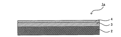
- FIG. 1 is a schematic cross-sectional view showing an example of the thermally conductive sealing member of the present invention.
- a heat conductive sealing member 1 a illustrated in FIG. 1 is formed on a metal base 2, a metal base 2, an insulating layer 3 having thermal conductivity and containing at least polyimide, and an insulating layer 3. And an adhesive layer 4 having heat resistance.
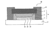
- FIG. 2 is a schematic cross-sectional view showing an example of an EL element sealed using the thermally conductive sealing member of the present invention.
- 2 includes a transparent substrate 21, a transparent electrode layer 22 formed on the transparent substrate 21, an EL layer 23 formed on the transparent electrode layer 22 and having at least a light emitting layer, and an EL layer.
- a back electrode layer 24 formed on the heat conductive sealing member 1a formed so as to cover the transparent electrode layer 22, the EL layer 23, and the back electrode layer 24, and a heat conductive seal on the transparent substrate 21.
- a sealing resin portion 25 formed so as to surround the outer periphery of the stopper member 1a, and the adhesive layer 4 of the heat conductive sealing member 1a covers the transparent electrode layer 22, the EL layer 23, and the back electrode layer 24. In this way, it is adhered to the transparent substrate 21.
- a metal substrate is excellent in thermal conductivity and gas barrier properties.
- the insulating layer contains polyimide.
- polyimide is smaller than metal, but has a relatively high thermal conductivity in the resin.
- the pressure-sensitive adhesive used for the pressure-sensitive adhesive layer is inferior in thermal conductivity compared to metal and polyimide, but has higher thermal conductivity than air.
- the pressure-sensitive adhesive is flexible at room temperature and has high followability to unevenness, and can adhere to an EL element having unevenness on the surface.
- the adhesive layer is more efficient for generating heat from the light emitting layer to the metal substrate. Play a role to tell. Therefore, the thermally conductive sealing member of the present invention has a high moisture barrier property and can conduct or radiate heat quickly.
- the adhesive layer is transparent when the adhesive layer of the thermally conductive sealing member is attached to a transparent substrate that supports the EL element.
- the adhesive layer is adhered to the transparent substrate so as to cover the transparent electrode layer, the EL layer, and the back electrode layer, and the thermally conductive sealing member and the transparent substrate There will be no gap between them. Therefore, heat conductivity is high, adverse effects due to heat generation can be suppressed, uniform light emission without light emission unevenness can be realized, lifetime can be shortened, and element destruction can be reduced.
- the heat conductive sealing member is excellent in gas barrier properties, it is possible to reduce moisture permeation from the heat conductive sealing member side, and to stably maintain the light emission characteristics over a long period of time. be able to.
- a heat conductive sealing member, a transparent electrode layer, an EL layer, and a back electrode layer are attached by sticking the adhesion layer of a heat conductive sealing member to the transparent substrate which supports EL element.
- the EL element can be sealed by a simple method without requiring a complicated process.
- the adhesive layer of the thermally conductive sealing member can be attached to the transparent substrate supporting the EL element at a low temperature such as room temperature, which is advantageous for sealing an EL element that is vulnerable to heat. Also, it has an advantage that it is easy to handle.
- the insulating layer is made of polyimide, and polyimide generally has excellent heat resistance.
- the adhesive layer has heat resistance. That is, in the thermally conductive sealing member of the present invention, both the insulating layer and the adhesive layer have heat resistance. Therefore, for example, when an EL element is sealed using the heat conductive sealing member of the present invention, deterioration of the insulating layer and the adhesive layer due to heat generation can be suppressed.
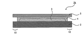
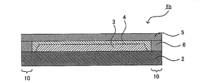
- FIG. 3 is a schematic sectional view showing another example of the thermally conductive sealing member of the present invention.
- the heat conductive sealing member 1b illustrated in FIG. 3 is formed on the metal base material 2, the metal base material 2, and has heat conductivity and includes at least a polyimide-containing insulating layer 3 and the insulating layer 3. And has a heat-resistant adhesive layer 4 and a release layer 5 formed on the adhesive layer 4.
- a release layer may be formed as illustrated in FIG. Also in this case, the peeling layer is peeled off from the thermally conductive sealing member to expose the adhesive layer, and the adhesive layer of the thermally conductive sealing member is attached to a transparent substrate that supports the EL element, as illustrated in FIG. Thus, the EL element 20 can be sealed.
- Insulating layer The insulating layer in the present invention is formed on a metal substrate, has thermal conductivity, and contains at least polyimide.
- the insulating layer has an insulating property.
- the volume resistance of the insulating layer is preferably 1.0 ⁇ 10 9 ⁇ ⁇ m or more, more preferably 1.0 ⁇ 10 10 ⁇ ⁇ m or more, and 1.0 ⁇ 10 11. More preferably, it is ⁇ ⁇ m or more.
- the volume resistance can be measured by a method based on standards such as JIS K6911, JIS C2318, and ASTM D257.
- the insulating layer has thermal conductivity.
- the insulating layer contains polyimide, and the thermal conductivity of the insulating layer is usually about 0.1 W / mK to 1.0 W / mK.
- the larger the thermal conductivity the better.
- the larger the thermal conductivity the better the thermal conductivity at the same film thickness.
- the thermal conductivity can be measured by a laser flash method, a hot wire method, a flat plate heat flow meter method, a temperature gradient method, or the like, and is appropriately selected according to the material of the insulating layer.
- the insulating layer contains polyimide, and preferably contains polyimide as a main component.
- polyimide has water absorption. Since many semiconductor materials used in EL elements, organic thin-film solar cells, solid-state imaging elements, etc. are vulnerable to moisture, the insulating layer preferably has a relatively low water absorption in order to reduce moisture inside the element. .
- One index of water absorption is the hygroscopic expansion coefficient. Therefore, it is preferable that the hygroscopic expansion coefficient of the insulating layer is as small as possible. Specifically, it is preferably in the range of 0 ppm /% RH to 15 ppm /% RH, more preferably 0 ppm /% RH to 12 ppm /% RH.
- the hygroscopic expansion coefficient of the insulating layer is in the above range, the water absorption of the insulating layer can be made sufficiently small, and the heat conductive sealing member can be easily stored. When sealing an element, the process becomes simple.
- the smaller the hygroscopic expansion coefficient of the insulating layer the better the dimensional stability of the insulating layer.
- the thermal conductive sealing member warps as the humidity rises due to the difference in expansion coefficient from the metal base material where the hygroscopic expansion coefficient is almost zero. Adhesiveness may decrease.
- the hygroscopic expansion coefficient is measured as follows. First, a film having only an insulating layer is produced. Insulating layer film can be made by using a heat-resistant film (Upilex S 50S (manufactured by Ube Industries, Ltd.)) or a glass substrate and then peeling off the insulating layer film, Further, there is a method of obtaining an insulating layer film by preparing an insulating layer film and then removing the metal by etching. Next, the obtained insulating layer film is cut into a width of 5 mm and a length of 20 mm to obtain an evaluation sample.
- a heat-resistant film Upilex S 50S (manufactured by Ube Industries, Ltd.)
- the hygroscopic expansion coefficient is measured by a humidity variable mechanical analyzer (Thermo Plus TMA8310 (manufactured by Rigaku Corporation)). For example, the temperature is kept constant at 25 ° C., and the sample is first stabilized in a humidity of 15% RH. After maintaining the state for approximately 30 minutes to 2 hours, the humidity of the measurement site is 20%. RH and hold for 30 minutes to 2 hours until the sample is stable. After that, the humidity is changed to 50% RH, and the difference between the sample length when it becomes stable and the sample length when it becomes stable at 20% RH is the change in humidity (in this case 50-20). 30) and the value divided by the sample length is the hygroscopic expansion coefficient (CHE). At the time of measurement, the tensile weight is set to 1 g / 25000 ⁇ m 2 so that the weight per cross-sectional area of the evaluation sample becomes the same.
- Thermo Plus TMA8310 manufactured by Rigaku Corporation
- the linear thermal expansion coefficient of the insulating layer is preferably 15 ppm / ° C. or less, more preferably 10 ppm / ° C. or less, more preferably from the viewpoint of dimensional stability. Is 5 ppm / ° C. or less.
- the heat conductive sealing member of the present invention is preferably flat in the temperature environment in the range of 0 ° C. to 100 ° C.
- the thermally conductive sealing member will warp due to changes in the thermal environment.
- the heat-conductive sealing member is flat means that the heat-conductive sealing member is cut into a strip shape having a width of 10 mm and a length of 50 mm, and one short side of the obtained sample is placed on a horizontal and smooth table. It means that the flying distance from the surface of the other short side of the sample is 1.0 mm or less.
- the linear thermal expansion coefficient of the insulating layer is preferably in the range of 0 ppm / ° C. to 30 ppm / ° C., more preferably in the range of 0 ppm / ° C. to 25 ppm / ° C., from the viewpoint of dimensional stability. More preferably, it is in the range of 0 ppm / ° C. to 10 ppm / ° C.
- the linear thermal expansion coefficient is measured as follows. First, a film having only an insulating layer is produced. The method for producing the insulating layer film is as described above. Next, the obtained insulating layer film is cut into a width of 5 mm and a length of 20 mm to obtain an evaluation sample.
- the linear thermal expansion coefficient is measured by a thermomechanical analyzer (for example, Thermo Plus TMA8310 (manufactured by Rigaku Corporation)). The measurement conditions are 10 ° C./min for the rate of temperature increase, 1 g / 25,000 ⁇ m 2 of tensile load so that the weight per cross-sectional area of the evaluation sample is the same, and the average linear thermal expansion within the range of 100 ° C. to 200 ° C.
- the coefficient is the linear thermal expansion coefficient (CTE).
- the polyimide constituting the insulating layer is not particularly limited as long as it satisfies the above characteristics.
- the structure of polyimide it is possible to control insulation and thermal conductivity, and to control the hygroscopic expansion coefficient and linear thermal expansion coefficient.
- the polyimide is preferably a polyimide containing an aromatic skeleton from the viewpoint of making the linear thermal expansion coefficient, hygroscopic expansion coefficient, and thermal conductivity of the insulating layer suitable for the thermally conductive sealing member of the present invention.
- polyimides polyimides containing aromatic skeletons are derived from their rigid and highly planar skeletons, which have excellent heat resistance and insulation properties in thin films, high thermal conductivity, and low linear thermal expansion coefficient.
- the insulating layer of the heat conductive sealing member of the present invention is preferably used.
- polyimide Since polyimide is required to have low hygroscopic expansion and low linear thermal expansion, it is preferable that the polyimide contains a repeating unit represented by the following formula (I). Such polyimide exhibits high heat resistance and insulation properties derived from its rigid skeleton, and exhibits linear thermal expansion equivalent to that of metal. Furthermore, the hygroscopic expansion coefficient can be reduced.
- R 1 is a tetravalent organic group
- R 2 is a divalent organic group
- R 1 and R 2 that are repeated may be the same or different.
- n is a natural number of 1 or more.
- R 1 is generally a structure derived from tetracarboxylic dianhydride
- R 2 is a structure derived from diamine.
- tetracarboxylic dianhydrides applicable to polyimide include ethylene tetracarboxylic dianhydride, butane tetracarboxylic dianhydride, cyclobutane tetracarboxylic dianhydride, cyclopentane tetracarboxylic dianhydride, pyro Merit acid dianhydride, 3,3 ′, 4,4′-benzophenone tetracarboxylic dianhydride, 2,2 ′, 3,3′-benzophenone tetracarboxylic dianhydride, 3,3 ′, 4,4 '-Biphenyltetracarboxylic dianhydride, 2,2', 3,3'-biphenyltetracarboxylic dianhydride, 2,2 ', 6,6'-biphenyltetracarboxylic dianhydride, 2,2- Bis (3,4-dicarboxyphenyl) propane dianhydride, 2,2-bis (2,
- the tetracarboxylic dianhydride preferably used from the viewpoint of the heat resistance of polyimide, the coefficient of linear thermal expansion, etc. is an aromatic tetracarboxylic dianhydride.
- Particularly preferred tetracarboxylic dianhydrides include pyromellitic dianhydride, merophanic dianhydride, 3,3 ′, 4,4′-benzophenone tetracarboxylic dianhydride, 3,3 ′, 4.
- 4′-biphenyltetracarboxylic dianhydride 2,3,3 ′, 4′-biphenyltetracarboxylic dianhydride, 2,3,2 ′, 3′-biphenyltetracarboxylic dianhydride, 2, 2 ′, 6,6′-biphenyltetracarboxylic dianhydride, bis (3,4-dicarboxyphenyl) ether dianhydride, 2,2-bis (3,4-dicarboxyphenyl) -1,1, Examples thereof include 1,3,3,3-hexafluoropropane dianhydride and bis (3,4-dicarboxyphenyl) ether dianhydride.
- 3,3 ′, 4,4′-biphenyltetracarboxylic dianhydride, 2,3,3 ′, 4′-biphenyltetracarboxylic dianhydride, 2, 3,2 ′, 3′-biphenyltetracarboxylic dianhydride and bis (3,4-dicarboxyphenyl) ether dianhydride are particularly preferred.
- a tetracarboxylic dianhydride into which fluorine is introduced is used as the tetracarboxylic dianhydride to be used in combination, the hygroscopic expansion coefficient of polyimide decreases.
- a polyimide precursor having a skeleton containing fluorine is difficult to dissolve in a basic aqueous solution, and it is necessary to perform development with a mixed solution of an organic solvent such as alcohol and a basic aqueous solution.
- pyromellitic dianhydride merophanic dianhydride, 3,3 ′, 4,4′-biphenyltetracarboxylic dianhydride, 2,3,3 ′, 4′-biphenyltetracarboxylic dianhydride
- rigid tetracarboxylic dianhydrides such as 2,3,2 ′, 3′-biphenyltetracarboxylic dianhydride and 1,4,5,8-naphthalenetetracarboxylic dianhydride are used, This is preferable because the linear thermal expansion coefficient is small.
- 3,3 ′, 4,4′-biphenyltetracarboxylic dianhydride and 2,3,3 ′, 4′-biphenyltetracarboxylic acid are used from the viewpoint of the balance between the linear thermal expansion coefficient and the hygroscopic expansion coefficient.
- the dianhydride, 2,3,2 ′, 3′-biphenyltetracarboxylic dianhydride is particularly preferred.
- the transparency of the polyimide precursor is improved, so that it becomes a highly sensitive photosensitive polyimide precursor.
- the heat resistance and insulation of polyimide tend to be inferior compared to aromatic polyimide.
- polyimide contains any structure of the above formula, it is derived from these rigid skeletons and exhibits low linear thermal expansion and low hygroscopic expansion. Furthermore, there is an advantage that it is easily available on the market and is low cost.
- the polyimide having the structure as described above is a polyimide that exhibits high heat resistance and a low linear thermal expansion coefficient. Therefore, the content of the structure represented by the above formula is preferably closer to 100 mol% of R 1 in the above formula (I), but at least 33% or more of R 1 in the above formula (I) is contained. do it. Among them, the content of the structure represented by the above formula is preferably 50 mol% or more, more preferably 70 mol% or more, of R 1 in the above formula (I).
- a diamine component applicable to polyimide can also be used alone or in combination of two or more diamines.
- the diamine component used is not particularly limited, and examples thereof include p-phenylenediamine, m-phenylenediamine, o-phenylenediamine, 3,3′-diaminodiphenyl ether, 3,4′-diaminodiphenyl ether, 4,4 ′.
- a diamine obtained by substituting some or all of the hydrogen atoms on the aromatic ring of the diamine with a substituent selected from a fluoro group, a methyl group, a methoxy group, a trifluoromethyl group, or a trifluoromethoxy group may be used. it can.
- any one or more of ethynyl group, benzocyclobuten-4′-yl group, vinyl group, allyl group, cyano group, isocyanate group, and isopropenyl group serving as a crosslinking point may be used. Even if it introduce
- the diamine can be selected depending on the desired physical properties. If a rigid diamine such as p-phenylenediamine is used, the polyimide has a low expansion coefficient.
- rigid diamines include p-phenylenediamine, m-phenylenediamine, 1,4-diaminonaphthalene, 1,5-diaminonaphthalene, 2, 6 as diamines in which two amino groups are bonded to the same aromatic ring. -Diaminonaphthalene, 2,7-diaminonaphthalene, 1,4-diaminoanthracene and the like.
- diamines in which two or more aromatic rings are bonded by a single bond, and two or more amino groups are each bonded directly or as part of a substituent on a separate aromatic ring for example, Some are represented by the following formula (II). Specific examples include benzidine and the like.
- a is 0 or a natural number of 1 or more, and the amino group is bonded to the meta position or the para position with respect to the bond between the benzene rings.
- a diamine having a substituent at a position where the amino group on the benzene ring is not substituted and which does not participate in the bond with another benzene ring can also be used. These substituents are monovalent organic groups, but they may be bonded to each other.
- polyimide precursors containing fluorine, particularly polyamic acid are difficult to dissolve in a basic aqueous solution, and when an insulating layer is partially formed on a metal substrate, alcohol or the like may be used during processing of the insulating layer. It may be necessary to develop with a mixed solution with an organic solvent.
- the adhesion to the metal substrate is improved and the elastic modulus of the polyimide is lowered.
- the glass transition temperature can be lowered.
- the selected diamine is preferably an aromatic diamine from the viewpoint of heat resistance.
- the diamine may be an aliphatic diamine or siloxane within a range not exceeding 60 mol%, preferably not exceeding 40 mol%.
- Non-aromatic diamines such as diamines may be used.
- R 3 is a divalent organic group, an oxygen atom, a sulfur atom, or a sulfone group
- R 4 and R 5 are a monovalent organic group or a halogen atom.
- polyimide contains any structure of the above formula, it is derived from these rigid skeletons and exhibits low linear thermal expansion and low hygroscopic expansion. Furthermore, there is an advantage that it is easily available on the market and is low cost.
- the heat resistance of a polyimide improves and a linear thermal expansion coefficient becomes small. Therefore, the closer to 100 mol% of R2 in the formula (I), the better, but it is sufficient to contain at least 33% of R2 in the formula (I).
- the content of the structure represented by the above formula is preferably 50 mol% or more, more preferably 70 mol% or more, of R2 in the above formula (I).
- the insulating layer should just contain the polyimide which has a repeating unit represented by the above-mentioned formula (I), and if necessary, this polyimide and another adhesive polyimide are laminated. They may be combined or combined to be used as an insulating layer.
- the polyimide having the repeating unit represented by the above formula (I) may be obtained using a photosensitive polyimide or a photosensitive polyimide precursor.
- the photosensitive polyimide can be obtained using a known method. For example, an ethylenic double bond may be introduced into the carboxyl group of polyamic acid by an ester bond or an ionic bond, and a photoradical initiator may be mixed into the resulting polyimide precursor to form a solvent-developed negative photosensitive polyimide precursor. it can.
- a naphthoquinone diazide compound is added to polyamic acid or a partially esterified product thereof to obtain an alkali development positive photosensitive polyimide precursor
- an nifedipine compound is added to polyamic acid to form an alkali development negative photosensitive polyimide precursor.
- a photobase generator can be added to the polyamic acid to obtain an alkali development negative photosensitive polyimide precursor.
- photosensitive polyimide precursors are added with 15% to 35% of a photosensitizing component based on the weight of the polyimide component. Therefore, even if heating is performed at 300 ° C. to 400 ° C. after pattern formation, residues derived from the photosensitizing component remain in the polyimide. Since these residuals cause the linear thermal expansion coefficient and the hygroscopic expansion coefficient to increase, the reliability of the EL element is higher when the photosensitive polyimide precursor is used than when the non-photosensitive polyimide precursor is used. Tend to decrease. However, a photosensitive polyimide precursor obtained by adding a photobase generator to polyamic acid can form a pattern even if the amount of photobase generator added as an additive is 15% or less.
- the polyimide precursor used for polyimide can be developed with a basic aqueous solution, from the viewpoint of ensuring the safety of the work environment and reducing process costs when partially forming the insulating layer on the metal substrate. preferable. Since the basic aqueous solution can be obtained at a low cost and the waste liquid treatment cost and the facility cost for ensuring work safety are low, production at a lower cost is possible.
- the insulating layer should just contain a polyimide, it is preferable to have a polyimide as a main component especially.
- a polyimide By using polyimide as a main component, an insulating layer having excellent insulating properties and heat resistance can be obtained.
- polyimide By using polyimide as a main component, the insulating layer can be thinned, the thermal conductivity of the insulating layer is improved, and a thermally conductive sealing member having more excellent thermal conductivity can be obtained.
- that an insulating layer has a polyimide as a main component means that an insulating layer contains a polyimide to the extent which satisfy
- the content of polyimide in the insulating layer is 75% by mass or more, preferably 90% by mass or more, and it is particularly preferable that the insulating layer is made of only polyimide. If the content of the polyimide in the insulating layer is in the above range, it is possible to exhibit sufficient characteristics to achieve the object of the present invention. The characteristics such as property are improved.
- the insulating layer may contain additives such as a leveling agent, a plasticizer, a surfactant, and an antifoaming agent as necessary.
- the thickness of the insulating layer is not particularly limited as long as it has both insulating properties and thermal conductivity. Specifically, it is preferably in the range of 0.3 ⁇ m to 100 ⁇ m, more preferably 0. Within the range of 5 ⁇ m to 50 ⁇ m, more preferably within the range of 1 ⁇ m to 20 ⁇ m. This is because if the thickness of the insulating layer is too thin, sufficient insulation may not be obtained, and if the thickness of the insulating layer is too thick, the thermal conductivity may decrease.
- the insulating layer may contain a hygroscopic agent. This is because moisture penetration from the outside can be more effectively prevented by moisture absorption by the moisture absorbent in the insulating layer. Thereby, when an EL element is produced using the thermally conductive sealing member of the present invention, deterioration of element performance can be further suppressed.
- the hygroscopic agent is not particularly limited as long as it has at least a function of adsorbing moisture, but among them, it is a compound that chemically adsorbs moisture and maintains a solid state even when it absorbs moisture. Is preferred. Examples of such compounds include metal oxides, metal inorganic acid salts, and organic acid salts. In particular, alkaline earth metal oxides and sulfates are preferred. Examples of the alkaline earth metal oxide include calcium oxide, barium oxide, magnesium oxide, and strontium oxide. Examples of the sulfate include lithium sulfate, sodium sulfate, gallium sulfate, titanium sulfate, and nickel sulfate.
- hygroscopic organic compounds such as silica gel and polyvinyl alcohol can also be used.
- calcium oxide, barium oxide, and silica gel are particularly preferable. This is because these hygroscopic agents are highly hygroscopic.
- the content of the hygroscopic agent is not particularly limited, but is preferably in the range of 5 to 80 parts by mass, more preferably 5 parts per 100 parts by mass of the total amount of the hygroscopic agent and the polyimide. It is in the range of 60 parts by mass to 60 parts by mass, more preferably in the range of 5 to 50 parts by mass.
- the insulating layer may be formed on the entire surface of the metal substrate, or may be partially formed on the metal substrate. Especially, it is preferable that the insulating layer is partially formed on the metal base material. That is, it is preferable that the metal substrate exposed region where the insulating layer and the adhesive layer are not present and the metal substrate is exposed is provided on the surface of the metal substrate where the insulating layer and the adhesive layer are formed. . By having such a metal substrate exposed region, when the EL element is sealed using the thermally conductive sealing member of the present invention, the sealing resin portion is made of metal without an insulating layer or an adhesive layer.
- the sealing resin part in the exposed area of the metal substrate it is possible to divide the EL elements in the plane or to seal them in a multi-faceted state with high productivity. There is an advantage that an element can be manufactured.
- the metal substrate exposed region can also be a through-hole for penetrating the insulating layer and the adhesive layer and electrically connecting to the metal substrate.
- FIG. 4A is a top view
- FIG. 4B is a cross-sectional view taken along line AA of FIG. 4A.
- the adhesive layer and the release layer are omitted.
- an insulating layer is formed on the entire surface of the metal base and the end face of the insulating layer is exposed, generally polyimide has a water absorption property. Since it is relatively high, moisture may enter from the end face of the insulating layer during manufacturing or driving. This moisture deteriorates the device performance or changes the dimensions of the insulating layer. Therefore, an insulating layer is not formed on the outer edge portion of the metal substrate, and it is preferable to reduce as much as possible the portion where the insulating layer containing polyimide is directly exposed to the outside air.
- a method for forming the insulating layer for example, a method of applying a polyimide solution or a polyimide precursor solution on a metal substrate can be used.
- a method of applying a polyimide precursor solution is preferable. This is because polyimide generally has poor solubility in a solvent.
- polyimide having high solubility in a solvent is inferior in physical properties such as heat resistance, linear thermal expansion coefficient, and hygroscopic expansion coefficient.
- a coating method for example, a spin coating method, a die coating method, a dip coating method, a bar coating method, a gravure printing method, a screen printing method, or the like can be used.
- a polyimide film when forming a laminate of a metal substrate and an insulating layer, can be used.
- a polyimide film When using a polyimide film, a laminated body of a metal substrate and an insulating layer can be obtained by vapor-depositing a metal material on the polyimide film.
- a printing method, a photolithography method, a direct processing method using a laser, or the like can be used as the forming method.
- a photolithography method for example, after forming a polyamic acid, which is a polyimide precursor, on a metal substrate, a photosensitive resin film is formed on the polyamic acid film, and a photosensitive resin film pattern is formed by a photolithography method.
- a method of removing the photosensitive resin film pattern and imidizing the polyamic acid simultaneously with the formation of the photosensitive resin film pattern, A method of developing the film, and then removing the photosensitive resin film pattern and imidizing the polyamic acid; forming a photosensitive resin film pattern on the insulating layer in the state of a laminate of a metal substrate and an insulating layer; After etching the insulating layer along the pattern by wet etching or dry etching, photosensitive resin Method of removing a turn; patterning one metal substrate of a laminate in which a metal substrate, an insulating layer, and a metal substrate are laminated, etching the insulating layer using the pattern as a mask, and then removing the metal pattern Method: The method of forming the pattern of an insulating layer directly on a metal base material using photosensitive polyimide or a photosensitive polyimide precursor is mentioned. Examples of the printing method include
- Adhesive layer The adhesive layer in this invention is formed on an insulating layer, and has heat resistance.
- the heat resistance of the adhesive layer heating in the production process of the heat conductive sealing member of the present invention, or in the case of sealing the EL element using the heat conductive sealing member of the present invention, the production process of the EL element As long as it can withstand the heating in step 1 and the heat generation of the EL element, it is preferable that no gas is generated from the adhesive layer at the process temperature.
- the 5% weight reduction temperature of the pressure-sensitive adhesive constituting the pressure-sensitive adhesive layer is preferably 80 ° C. or higher, more preferably 100 ° C. or higher, and further preferably 120 ° C. or higher.
- the pressure-sensitive adhesive is decomposed by heat generated during light emission of the EL element, and there is a possibility that the element characteristics are deteriorated by a substance generated at the decomposition. Moreover, the adhesiveness of the pressure-sensitive adhesive layer itself is lowered due to thermal deterioration, the adhesion with the element is deteriorated, and the element may be peeled off.
- the 5% weight loss temperature was measured by raising the temperature at a heating rate of 10 ° C./min in a nitrogen atmosphere using a thermogravimetric analyzer or a differential thermobalance (for example, Thermo Plus TG8120 (manufactured by Rigaku Corporation)). Value.
- the adhesive layer is bonded to the transparent substrate so as to cover the transparent electrode layer, the EL layer, and the back electrode layer when, for example, the EL element is sealed using the heat-resistant sealing member of the present invention, Provide irregularity tracking.
- the storage elastic modulus at room temperature of the pressure-sensitive adhesive layer is preferably 1.0 ⁇ 10 2 Pa or more and 1.0 ⁇ 10 7 Pa or less, and 1.0 ⁇ 10 3 Pa or more and 1.0 ⁇ still more preferably 10 6 Pa or less, even more preferably at most 1.0 ⁇ 10 4 Pa or more 1.0 ⁇ 10 6 Pa.
- room temperature means 25 degreeC.
- the storage elastic modulus at room temperature of the pressure-sensitive adhesive layer is in the above range, practically sufficient pressure-sensitive adhesiveness and good unevenness followability can be obtained.
- the storage elastic modulus at room temperature is smaller than the above range, the adhesive layer becomes brittle and easily causes cohesive failure.
- corrugation is hard to be expressed.
- the storage elastic modulus is an index of hardness / softness.
- the level difference due to the The storage elastic modulus is a value measured by using a dynamic viscoelasticity measuring apparatus (for example, RSA3 (manufactured by TA Instruments) under conditions of a frequency of 1 Hz and a temperature rising rate of 5 ° C./min.
- a dynamic viscoelasticity measuring apparatus for example, RSA3 (manufactured by TA Instruments) under conditions of a frequency of 1 Hz and a temperature rising rate of 5 ° C./min.
- the glass transition temperature (Tg) of the adhesive which comprises an adhesion layer is 100 degrees C or less, More preferably, it is 50 degrees C or less, More preferably, it is 30 degrees C or less.
- Tg of the adhesive the temperature at which the adhesive layer of the thermally conductive sealing member is attached to the transparent substrate supporting the EL element. If it is lower than this, it will be difficult to follow the unevenness. Accordingly, the Tg of the pressure-sensitive adhesive is preferably relatively low, and particularly preferably room temperature or lower. If Tg of an adhesive is the said range, the temperature at the time of sticking the adhesion layer of a heat conductive sealing member on the transparent substrate which supports an EL element can be made low.
- the adhesive layer usually has an insulating property.
- the volume resistance of the insulating layer is preferably 1.0 ⁇ 10 7 ⁇ ⁇ m or more, more preferably 1.0 ⁇ 10 8 ⁇ ⁇ m or more, and 1.0 ⁇ 10 9. More preferably, it is ⁇ ⁇ m or more.
- the volume resistance can be measured by a method based on standards such as JIS K6911, JIS C2318, and ASTM D257.
- the pressure-sensitive adhesive used in the pressure-sensitive adhesive layer is not particularly limited as long as it satisfies the above-described characteristics and does not adversely affect the EL layer when the heat-resistant sealing member of the present invention is used in an EL element.
- thermosetting resins such as polyimide resins, silicone resins, epoxy resins, acrylic resins, rubber resins, polyester resins, photocurable resins, and acid-modified resins such as polyethylene and polypropylene And thermoplastic resins.
- thermosetting resins and photocurable resins are preferable.
- the polyimide resin is excellent in heat resistance and thermal conductivity. Acrylic resins have higher heat resistance than rubber resins, are general-purpose adhesives, and are advantageous in terms of cost.
- polyester resins have the advantage of higher heat resistance and adhesive strength than acrylic resins.
- Silicone resins have the advantage of higher heat resistance than acrylic resins.
- polyimide resins and silicone resins are preferable.
- a non-silicone resin is preferable, and a polyimide resin is preferable because of excellent heat resistance and thermal conductivity.
- the pressure-sensitive adhesive may be a curable pressure-sensitive adhesive.
- the curable pressure-sensitive adhesive means an adhesive that has adhesiveness during the production of the element and is cured after the element is produced.
- the curable pressure-sensitive adhesive has an advantage that the adhesiveness to an object to be sealed becomes stronger.
- the thermally conductive sealing member of the present invention is applied to a flexible EL element, if a curable adhesive is used, a crack occurs in the cured portion of the adhesive layer when the element is bent, and the element deteriorates. There is a case to let you.
- the curable pressure-sensitive adhesive the above-mentioned thermosetting resin or photocurable resin can be used.
- the polyimide resin preferably contains a repeating unit represented by the following formula (III).
- R 6 is a tetravalent organic group
- R 7 is a divalent organic group
- R 6 and R 7 that are repeated may be the same or different from each other.
- It is a natural number of 1 or more.
- R 6 is generally a structure derived from tetracarboxylic dianhydride
- R 7 is a structure derived from diamine.
- the diamine applied to the polyimide resin preferably includes at least an aliphatic diamine.
- the aliphatic diamine refers to an aliphatic diamine in which the carbon atom bonded to the nitrogen atom of the amino group connecting the two amino groups is an aliphatic carbon.
- the aromatic diamine refers to an aromatic diamine in which the carbon atom is aromatic. It is a group carbon.
- aromatic acid dianhydride is an aromatic acid dianhydride
- an aliphatic acid dianhydride is an aliphatic structure at the site where two acid anhydride groups are connected. That's it.
- Examples of the polyimide resin having a repeating unit represented by the above formula (III) include a tetracarboxylic dianhydride represented by the following formula (1), a tetracarboxylic acid represented by the following formula (2), and the tetra A tetracarboxylic acid component composed of one or more compounds selected from carboxylic acid derivatives, and an aliphatic diamine represented by the following formula (3): the number of moles of the tetracarboxylic acid component is larger than the number of moles of the aliphatic diamine.
- Compound (B) obtained by mixing and heat-reacting polyimide (A) by mixing so as to be excessive, polyimide (A), and aromatic diamine represented by the following formula (4).
- thermosetting polymer comprising a bifunctional crosslinker such as a bismaleimide compound represented by the following formula (5), a bifunctional epoxy compound, or a bifunctional acrylate. It is preferably obtained by curing the bromide resin composition.
- a bifunctional crosslinker such as a bismaleimide compound represented by the following formula (5), a bifunctional epoxy compound, or a bifunctional acrylate. It is preferably obtained by curing the bromide resin composition.
- R 11 is a tetravalent organic group.
- R 11 is a tetravalent organic group, and Y 1 to Y 4 are independently hydrogen or a hydrocarbon group having 1 to 8 carbon atoms.
- X 1 is a divalent organic group having 1 to 221 carbon atoms in which an aliphatic group or an alicyclic group is directly bonded to an amino group, and an aromatic group is part of the structure thereof.
- X 2 is a divalent organic group having 6 to 27 carbon atoms in which an aromatic ring is directly bonded to an amino group, and an aliphatic group or an alicyclic group is part of the structure thereof. And may contain other substituents.
- Z is a divalent organic group.
- R 6 in formula (III) is R 11 in formula (1)
- R 7 in formula (III) is X 1 in formula (3) or X 2 in formula (4).
- thermosetting polyimide resin composition and the polyimide resin are obtained by a method including the following steps (1) to (4).
- -Step (1) Step of synthesizing polyimide (A) by heating reaction of tetracarboxylic acid component and aliphatic diamine-Step (2): Polyimide (A) synthesized in step (1) and aromatic diamine Step (3) for synthesizing polyimide (B) by heating reaction: The polyimide (B) synthesized in step (2) and a bifunctional cross-linking agent are blended and mixed at room temperature, thermosetting Step / Step (4) for Producing a Polyimide Resin Composition: Step for Obtaining a Polyimide Resin by Heat-curing the Thermosetting Polyimide Resin Composition Obtained in Step (3)
- examples of the aliphatic tetracarboxylic dianhydrides include 1,2,4,5-cyclohexanetetracarboxylic dianhydride, 1,2,3, 4-butanetetracarboxylic dianhydride, 1,2,3,4-cyclobutanetetracarboxylic dianhydride, 1,2,3,4-cyclopentanetetracarboxylic dianhydride, bicyclo [2.2.2 And oct-7-ene-2,3,5,6-tetracarboxylic dianhydride, dicyclohexyltetracarboxylic dianhydride and the like.
- examples of the aromatic tetracarboxylic dianhydride include pyromellitic dianhydride, 3,3 ′, 4,4′-biphenyltetracarboxylic acid dianhydride.
- aliphatic tetracarboxylic acids and derivatives thereof include, for example, 1,2,4,5-cyclohexanetetracarboxylic acid, 1,2,3,4 -Butanetetracarboxylic acid, 1,2,3,4-cyclobutanetetracarboxylic acid, 1,2,3,4-cyclopentanetetracarboxylic acid, bicyclo [2.2.2] oct-7-ene-2,3 , 5,6-tetracarboxylic acid, dicyclohexyltetracarboxylic acid, and the like, and esters thereof with alcohols having 1 to 8 carbon atoms.
- aromatic tetracarboxylic acids and derivatives thereof include, for example, pyromellitic acid, 3,3 ′, 4,4′-biphenyltetracarboxylic acid, 2, 3,3 ′, 4′-biphenyltetracarboxylic acid, 2,2-bis (3,4-dicarboxyphenyl) propane, 2,2-bis (2,3-dicarboxyphenyl) propane, 2,2-bis (3,4-dicarboxyphenyl) -1,1,1,3,3,3-hexafluoropropane, 2,2-bis (2,3-dicarboxyphenyl) -1,1,1,3,3 , 3-hexafluoropropane, bis (3,4-dicarboxyphenyl) sulfone, bis (3,4-dicarboxyphenyl) ether, bis (2,3-dicarboxyphenyl) ether, 3,3 , 4,4
- tetracarboxylic acids and derivatives of the tetracarboxylic acids those having a structure derived from cyclohexane or those having a structure derived from benzene are preferred, and more preferably derived from cyclohexane.
- Those having a structure are preferred, and particularly preferred is 1,2,4,5-cyclohexanetetracarboxylic dianhydride or 1,2,4,5-cyclohexanetetracarboxylic acid. Two or more types can be mixed and used.
- the aliphatic diamine of the above formula (3) is a diamine in which an aliphatic group or an alicyclic group is directly bonded to an amino group.
- X 1 of the aliphatic diamine of the formula (3) is preferably a divalent organic group having 1 to 221 carbon atoms, and part of its structure contains an aromatic group, an ether group, and other substituents. May be.
- the aliphatic diamine is a polyoxyalkylene diamine because adhesiveness is obtained in addition to flexibility.
- adheresiveness refers to the property of adhering by applying a slight pressure at room temperature for a short time without using water, solvent, heat, etc. Time This refers to the force required to peel off the adherend after applying a slight pressure to it.
- polyoxyalkylene diamine examples include polyoxypropylene diamine represented by the following formula (7), polyoxyethylene diamine represented by the following formula (8), and represented by the following formula (9).
- examples include polyoxybutylene diamine and copolymers thereof, and a polyoxypropylenediamine having a skeleton derived from propylene oxide and ethylene oxide represented by the following formula (6) as a polyoxypropylenediamine or copolymer of formula (7)
- Alkylene diamine is preferable for obtaining a polyimide resin having good adhesiveness.
- n 1 is the degree of polymerization of propylene oxide units.
- n 2 is the degree of polymerization of ethylene oxide units.
- n 3 is the degree of polymerization of the butylene oxide unit.
- the polyoxyalkylene diamine preferably has the following molecular weight in order to obtain a polyimide resin having good adhesiveness.
- the molecular weight of the polyoxyalkylenediamine of the above formula (6) is preferably 300 to 4000 (degree of polymerization of propylene oxide (a + c) is 1.0 to 9.4 (c is not 0), degree of polymerization of ethylene oxide (b) 3.7 to 79.8), more preferably 600 to 2000 (the degree of polymerization of propylene oxide (a + c) is 3.6 to 6.0 (c is not 0), the degree of polymerization of ethylene oxide (b) Is 9.0 to 38.7).
- the molecular weight of the polyoxypropylene diamine of the above formula (7) is preferably 230 to 4000 (degree of polymerization n 1 of propylene oxide is 2.6 to 68.0), more preferably 600 to 2000 (degree of polymerization of propylene oxide). n1 is 8.7 to 33.0).
- the molecular weight of the polyoxyethylenediamine of the above formula (8) is preferably 300 to 4000 (the degree of polymerization n 2 of ethylene oxide is 5.5 to 89.5), more preferably 600 to 2000 (the degree of polymerization n 2 of ethylene oxide is 2). 12.3-44.1).
- the molecular weight of the polyoxybutylene diamine of formula (9) is preferably 200-4000 (polymerization degree n 3 is from 1.6 to 54.3 butylene oxide), more preferably from 600 to 2000 (degree of polymerization of butylene oxide n 3 is 7.1 to 26.6).
- diamines other than polyoxyalkylene diamine for example, 4,4′-diaminodicyclohexylmethane, isophoronediamine, ethylenediamine, tetramethylenediamine, norbornanediamine, paraxylylenediamine
- diamines other than polyoxyalkylene diamine for example, 4,4′-diaminodicyclohexylmethane, isophoronediamine, ethylenediamine, tetramethylenediamine, norbornanediamine, paraxylylenediamine
- examples include 1,3-bis (aminomethyl) cyclohexane, 1,3-diaminocyclohexane, hexamethylenediamine, metaxylylenediamine, 4,4′-methylenebis (cyclohexylamine), bicyclohexyldiamine, and siloxane diamines. it can.
- diamine having an alicyclic structure such as 4,4'-diaminodicyclohexylmethane, isophoronediamine, 1,3-diaminocyclohexane, etc. from the viewpoint of easy high molecular weight and excellent heat resistance.
- diamines can be used alone or in admixture of two or more.
- the polyimide (A) which is the reaction product of the above step (1) is a tetra-compound composed of an aliphatic diamine and one or more compounds selected from tetracarboxylic dianhydrides, tetracarboxylic acids or derivatives of the tetracarboxylic acids. It is obtained by a method of adding a carboxylic acid component and causing an imidization reaction.
- the polyimide (A) which is the reaction product of the above step (1) is a tetracarboxylic dianhydride represented by the above formula (1), a tetracarboxylic acid represented by the above formula (2) or the tetracarboxylic acid.
- the tetracarboxylic acid component comprising one or more compounds selected from the above derivatives is preferably in a ratio of 1.01 mol to 2 mol, more preferably 1 mol to 1 mol of the aliphatic diamine represented by the above formula (3). Is preferably synthesized by blending at a ratio of 1.5 mol or more and 2 mol or less.
- both ends of the reaction product in the above step (1) are not groups derived from the tetracarboxylic acid component. It is not preferable to react with an aromatic diamine described later.
- tetracarboxylic acid components When one or more of the tetracarboxylic acid components are blended in a ratio of more than 2 moles with respect to 1 mole of the aliphatic diamine, a large amount of unreacted tetracarboxylic acid components remain and monomer components remain, resulting in a decrease in heat resistance. There is a risk of causing.
- the polyimide (A) can be obtained by performing a thermal imidization reaction in the absence of a solvent, but various organic solvents may be used. Specifically, one or more solvents such as N, N-dimethylacetamide, N-methyl-2-pyrrolidone, N, N-dimethylformamide, dimethyl sulfoxide, hexamethylphosphoramide, tetramethylene sulfone are used. it can. In particular, N-methyl-2-pyrrolidone and N, N-dimethylacetamide are preferably used as the solvent. Further, xylene or toluene may be added in order to perform azeotropic dehydration. After the synthesis of the polyimide (A), it can be diluted with a low-boiling solvent such as tetrahydrofuran, acetone or methanol.
- a low-boiling solvent such as tetrahydrofuran, acetone or methanol.
- the aliphatic diamine may be used by dissolving in an organic solvent as described above, if necessary.
- the reaction temperature of the imidization reaction is preferably 150 to 200 ° C, and particularly preferably 180 to 200 ° C. When the temperature is lower than 150 ° C., the molecular weight is not sufficiently increased and a practical polyimide cannot be synthesized. If it is higher than 200 ° C., it is not economically preferable due to cost.
- the reaction time is preferably 1 to 12 hours, particularly 3 to 6 hours. When the time is shorter than 1 hour, the molecular weight is not sufficiently increased and a practical polyimide cannot be synthesized. If it is longer than 12 hours, it is not economically preferable due to cost problems.
- the imidization reaction may be performed by adding toluene or xylene as an azeotropic solvent. The formation of polyimide can be confirmed by characteristic absorption of imide rings near 1770 and 1700 cm ⁇ 1 by IR spectrum.
- the polyimide (B) in the above step (2) is obtained by a method in which an aromatic diamine is blended with the polyimide (A) obtained in the above step (1) and imidized.
- the aromatic diamine represented by the above formula (4) is preferably in a ratio of 0.02 mol to 2 mol, more preferably 1 mol, with respect to 1 mol of the aliphatic diamine used when the polyimide (A) is produced. It synthesize
- the aromatic diamine is blended in a ratio larger than 2 moles with respect to 1 mole of the aliphatic diamine, the ratio of the unreacted aromatic diamine increases, and the flexibility of the polyimide resin obtained in the subsequent steps is lowered. .
- the aromatic diamine of the above formula (4) is a diamine in which an aromatic ring is directly bonded to an amino group.
- X 2 is preferably a divalent organic group having 6 to 27 carbon atoms, and an aliphatic group, an alicyclic group, or other substituents may be included in a part of the structure.
- Examples of the aromatic diamine of the above formula (4) include 3,4'-diaminodiphenyl ether, 4,4'-diaminodiphenyl ether, 4,4'-diaminodiphenylmethane, 4,4'-diaminodiphenylsulfone, and m-phenylene.
- 4,4′-diaminodiphenyl ether is preferred, and these can be used alone or in admixture of two or more.
- the polyimide (B) can be obtained by performing a thermal imidization reaction in the absence of a solvent, but various organic solvents may be used. Specifically, high boiling point solvents such as N, N-dimethylacetamide, N-methyl-2-pyrrolidone, N, N-dimethylformamide, dimethyl sulfoxide, hexamethylphosphoramide, tetramethylene sulfone, and low such as tetrahydrofuran and acetone. One or more boiling solvents can be used. In particular, N-methyl-2-pyrrolidone and N, N-dimethylacetamide are preferably used as the solvent.
- xylene or toluene may be added in order to perform azeotropic dehydration.
- a low-boiling solvent such as tetrahydrofuran, acetone or methanol.
- the aromatic diamine may be used by dissolving it in an organic solvent as described above, if necessary.
- the reaction temperature of the imidization reaction is preferably 150 to 200 ° C, and particularly preferably 180 to 200 ° C. When the temperature is lower than 150 ° C., the molecular weight is not sufficiently increased and a practical polyimide cannot be synthesized. If it is higher than 200 ° C., it is economically unpreferable due to cost.
- the reaction time is preferably 1 to 12 hours, particularly 3 to 6 hours. If it is shorter than 1 hour, the molecular weight is not sufficiently increased and a practical polyimide cannot be synthesized. If it is longer than 12 hours, it is not economically preferable because of cost.
- the imidization reaction may be performed by adding toluene or xylene as an azeotropic solvent.
- thermosetting polyimide resin composition is obtained by blending polyimide (B) and a bifunctional crosslinking agent and mixing them at room temperature.
- the bifunctional crosslinking agent is preferably a bismaleimide compound or a bifunctional epoxy compound represented by the above formula (5) from the viewpoint of heat resistance. Examples of the bismaleimide compound of the above formula (5) include the following.
- a bismaleimide compound in which both ends of polyoxyalkylene diamine are sealed with maleic anhydride can also be used.
- N, N ′-(4,4′-diphenylmethane) bismaleimide represented by the following formula (10), N, N ′-[4,4′-bis ( 3-methyl-5-ethylphenyl) methane] bismaleimide.
- thermosetting polyimide resin composition in the step (3), the bismaleimide compound represented by the above formula (5) is used with respect to 1 mol of the aliphatic diamine used in producing the polyimide (A).
- a thermosetting polyimide resin composition giving a flexible polyimide resin is obtained. It is done.
- the bismaleimide compound is blended at a ratio of less than 0.25 mol with respect to 1 mol of the aliphatic diamine used when the polyimide (A) is produced, the crosslinking density of the polyimide resin is low and the strength is insufficient.
- the tetracarboxylic acid component is blended in a ratio of 1.01 mol to 2 mol with respect to 1 mol of the aliphatic diamine, and the aromatic diamine is mixed in a ratio of 0.02 mol to 2 mol with respect to 1 mol of the aliphatic diamine.
- the bismaleimide compound is blended in a ratio larger than 4 moles with respect to 1 mole of the aliphatic diamine, the flexibility of the polyimide resin is lowered.
- Examples of the solvent used for the production of the thermosetting polyimide resin composition in the above step (3) include N, N-dimethylacetamide, N-methyl-2-pyrrolidone, N, N-dimethylformamide, and hexamethylphosphoramide.
- Examples include amide solvents, ketone solvents such as methyl ethyl ketone and acetone, cyclic ether solvents such as 1,4-dioxane and tetrahydrofuran, and acetonitrile.
- an amide solvent such as N, N-dimethylacetamide, N-methyl-2-pyrrolidone, N, N-dimethylformamide, hexamethylphosphoramide and the like.
- thermosetting polyimide resin composition in the above step (3) is obtained by the following method.
- the polyimide (B) obtained in the step (2) and the bifunctional crosslinking agent are dissolved in a solvent and mixed until a uniform liquid is obtained.
- the amount of the solvent in the thermosetting polyimide resin composition is preferably an amount that provides a viscosity capable of casting.
- the mixing temperature is preferably 0 ° C. to 80 ° C., more preferably 20 ° C. to 60 ° C. When the mixing temperature is lower than 0 ° C., the bifunctional cross-linking agent is difficult to dissolve and it is difficult to form a uniform liquid. When the mixing temperature is higher than 80 ° C., it is cured from a liquid state to a solid state during mixing.
- Adhesive polyimide resin may be obtained by thermosetting the obtained thermosetting polyimide resin composition, cast on a metal substrate on which an insulating layer is formed, or on a release layer to form a film, When cured, an adhesive layer containing a polyimide resin is obtained.
- the curing temperature is preferably 150 ° C. to 250 ° C. When the temperature is lower than 150 ° C., the uncured portion remains and the adhesive strength becomes too high, and when the release layer is attached to the adhesive layer, cohesive failure occurs when the release layer is peeled off, resulting in an adhesive residue. If it is higher than 250 ° C., it is economically unpreferable due to cost.
- the curing time is preferably 0.5 to 10 hours.
- (Acrylic resin) For the pressure-sensitive adhesive made of an acrylic resin, a (meth) acrylic acid alkyl ester polymer or a copolymer with another copolymerizable monomer is usually used.
- alkyl ester of (meth) acrylic acid alkyl ester include methyl ester, ethyl ester, butyl ester, 2-ethylhexyl ester, octyl ester, isononyl ester and the like.
- copolymerizable monomers include (meth) acrylic acid hydroxyhexyl ester (for example, hydroxyethyl ester, hydroxybutyl ester, hydroxyhexyl ester, etc.), (meth) acrylic acid glycidyl ester, (meth) acrylic acid. , Itaconic acid, maleic anhydride, (meth) acrylic acid amide, (meth) acrylic acid N-hydroxymethylamide, (meth) acrylic acid alkylaminoalkyl ester (for example, dimethylaminoethyl methacrylate), vinyl acetate, styrene, Examples include acrylonitrile.
- Examples of the adhesive made of acrylic resin include a thermosetting adhesive containing a thermosetting component and a radiation curable adhesive containing a radiation curable component.
- thermosetting type curing component examples include those having two or more functional groups such as isocyanate group (polyisocyanate) and epoxy group (epoxy resin) in the molecule, or 1,6-hexanediol diacrylate, A polyfunctional acrylate such as ethylene glycol diacrylate or a cross-linking agent such as a metal chelate compound is used. Note that the present invention is not particularly limited to these. Further, the blending amount of the crosslinking agent in the pressure-sensitive adhesive layer is preferably within the range of 0.2 to 10 parts by weight of the pressure-sensitive adhesive composition. When the amount is less than the above range, the crosslinking density may be low and curing may be insufficient. Moreover, when a compounding quantity exceeds the said range, a crosslinking density will become high too much and adhesive force may be unable to be maintained.
- the radiation curing component a reactive polymer having a carbon-carbon double bond in the molecule can be applied.
- the radiation curable component include trimethylolpropane tri (meth) acrylate, pentaerythritol tri (meth) acrylate, tetraethylene glycol di (meth) acrylate, 1,6-hexanediol di (meth) acrylate, neopentyl glycol diester.
- Examples include esterified products of (meth) acrylic acid and polyhydric alcohols, ester acrylate oligomers, 2-propenyl di-3-butenyl cyanurate, 2-hydroxyethylbis (2-acryloxyethyl) isocyanurate or isocyanurate compounds. It is done.
- a photopolymerization initiator for example, Irgacure 184, Irgacure 651, Irgacure 369, Irgacure 1800 (Ciba Specialty Chemicals), Chivacure TPO, Chivacure 107, Chivacure 173, Chivacure 1256 (Chitech), etc.
- a photopolymerization initiator for example, Irgacure 184, Irgacure 651, Irgacure 369, Irgacure 1800 (Ciba Specialty Chemicals), Chivacure TPO, Chivacure 107, Chivacure 173, Chivacure 1256 (Chitech), etc.
- polyester resin For the pressure-sensitive adhesive made of a polyester-based resin, a polyester resin having as its main component a copolyester obtained by polycondensation of an acid component and a polyol component is used.
- the polycondensation reaction is performed by a general known reaction such as a direct esterification method or a transesterification method.
- polyester resin examples include terephthalic acid, isophthalic acid, phthalic anhydride, ⁇ -naphthalenedicarboxylic acid, 5-sodium sulfoisophthalic acid, 5-potassium sulfoisophthalic acid and esters thereof, pimelic acid, suberic acid, Aliphatic dicarboxylic acids such as azelaic acid, sebacic acid, undecylene acid, dodecanedicarboxylic acid and esters thereof, and alicyclic dicarboxylic acids such as 1,4 cyclohexahydrophthalic anhydride are used. Of these, terephthalic acid, isophthalic acid and sebacic acid are preferred.
- the alcohol component of the polyester resin includes 1,2-propylene glycol, polytetramethylene oxide glycol, ethylene glycol, 1,3-propylene glycol, 1,3-butanediol, 1,4-butanediol, 1, 5-pentanediol, 1,6-hexanediol, 1,8-octanediol, 1,9-nonanediol, neopentyl glycol, 3-methylpentanediol, 2,2,3-trimethylpentanediol, diethylene glycol, triethylene Aliphatic glycols such as glycol and dipropylene glycol, alicyclic glycols such as 1,4-cyclohexanediol and 1,4-cyclohexanedimethanol, and aromatic glycols such as bisphenol A are used. Of these, 1,2-propylene glycol, polytetramethylene oxide glycol,
- the polyester resin can be produced by a conventionally known method for producing a polyester resin.
- a saturated polyester resin “Polyester” (registered trademark) XI-0001, XI-0002, and XI-1001 manufactured by Nippon Synthetic Chemical Industry Co., Ltd.
- XI-1002, XI-1003, XI-1004, and NP101 can be used.
- crosslinking agent examples include those having two or more functional groups such as isocyanate group (polyisocyanate) and epoxy group (epoxy resin) in the molecule, or 1,6-hexanediol diacrylate, triethylene glycol.
- a polyfunctional acrylate such as diacrylate or a metal chelate compound is used. Note that the present invention is not limited to these.
- the pressure-sensitive adhesive made of a silicone resin contains a silicone copolymer as the silicone resin.
- the silicone copolymer include addition polymerization type silicone copolymers having a vinylsilyl group (Si—CH ⁇ CH 2 group), a hydrosilyl group (Si—H group), and the like.
- the addition polymerization type silicone copolymer include SD4560, SD4570, SD4580, SD4584, SD4585, SD4585, SD4592, BY24-740 (manufactured by Toray Dow Corning), X-40-3068, X-40-3102, X -40-3103 and X-40-3104 (manufactured by Shin-Etsu Chemical) are used. Note that the present invention is not particularly limited to these.
- SRX212 manufactured by Dow Corning Toray
- CAT-PL-50T manufactured by Shin-Etsu Chemical
- the present invention is not limited to these.
- a compounding quantity of a catalyst 0.1 weight part or more of the said adhesive composition is preferable. This is because if the amount is less than the above range, the reaction of the silicone polymer may not be accelerated.
- a crosslinking agent may be added.
- the crosslinking agent for example, BY24-741, RD-1, and RD-2 (manufactured by Toray Dow Corning) are used. Note that the present invention is not limited to these.
- the amount of the crosslinking agent added is preferably in the range of 0.1 to 3 parts by weight of the pressure-sensitive adhesive composition. This is because when the blending amount is less than the above range, the effect of adding the crosslinking agent cannot be obtained remarkably. Moreover, if the blending amount exceeds the above range, the crosslinking density becomes too high, and as a result, the adhesive force cannot be maintained.
- the resin composition used for the adhesive layer preferably contains an additive that initiates a curing reaction during dehydration baking in the process of forming the adhesive layer.
- additives include a thermal base generator and a photobase generator.
- the adhesive layer may contain an antioxidant.
- an antioxidant When the amount of addition of the antioxidant increases, the heat resistance of the pressure-sensitive adhesive layer is improved, but the possibility that the reliability of the EL element is reduced due to the transfer of the antioxidant in the pressure-sensitive adhesive layer to the EL layer is increased. Therefore, the content of the antioxidant is preferably as small as possible in balance with heat resistance.
- the adhesive layer may contain a hygroscopic agent. This is because moisture penetration from the outside can be more effectively prevented by moisture absorption by the moisture absorbent in the adhesive layer. Thereby, when an EL element is produced using the thermally conductive sealing member of the present invention, deterioration of element performance can be further suppressed.
- the hygroscopic agent is the same as that described in the section of the insulating layer, and a description thereof is omitted here.
- the content of the hygroscopic agent is not particularly limited, but is preferably in the range of 5 to 80 parts by mass, more preferably 5 parts per 100 parts by mass of the total amount of the hygroscopic agent and the resin. It is in the range of 60 parts by mass to 60 parts by mass, more preferably in the range of 5 to 50 parts by mass.
- the content of the hygroscopic agent in the adhesive layer may be uniform or non-uniform. Especially, it is preferable that the hygroscopic agent contains only in the outer edge part of the adhesion layer.
- an EL element is sealed using the heat-resistant sealing member of the present invention
- the hygroscopic agent is contained in the part of the adhesive layer that contacts the back electrode layer, the surface of the adhesive layer is roughened by the hygroscopic agent, and the EL This is because the layer may be damaged. That is, when the EL element is sealed using the heat-resistant sealing member of the present invention, for example, it is preferable that a hygroscopic agent is contained in the portion of the adhesive layer that does not contact the back electrode layer.
- the adhesive layer may have a function as a white reflective layer.
- the thermally conductive sealing member of the present invention is used for an EL element, light emission from the EL layer is diffusely reflected on the surface of the pressure-sensitive adhesive layer, which is a white reflective layer. This is because it can be relaxed.
- the thickness of the pressure-sensitive adhesive layer is not particularly limited as long as it has both concave and convex followability and thermal conductivity. Specifically, the thickness is preferably in the range of 0.1 ⁇ m to 30 ⁇ m, more preferably 0.00. It is in the range of 5 ⁇ m to 20 ⁇ m, more preferably in the range of 1 ⁇ m to 10 ⁇ m. This is because if the thickness of the pressure-sensitive adhesive layer is too thin, sufficient follow-up capability may not be obtained, and if the thickness of the pressure-sensitive adhesive layer is too thick, the thermal conductivity may be reduced.
- the adhesive layer may be formed on the entire surface of the metal substrate, or may be partially formed on the metal substrate. Especially, it is preferable that the adhesion layer is partially formed on the metal base material. That is, as described in the section of the insulating layer, the metal base on which the insulating layer and the adhesive layer of the metal substrate are formed and the insulating layer and the adhesive layer are not present and the metal substrate is exposed. It is preferable that a material exposed region is provided.
- the adhesive layer is partially formed on the metal substrate, and the adhesive layer is made of polyimide resin and does not contain a hygroscopic agent, as illustrated in FIG. 5, the adhesive layer 4 Is preferably formed excluding the outer edge 10 of the metal substrate 2.
- the adhesive layer when an EL element is produced using the thermally conductive sealing member of the present invention, if the adhesive layer is formed on the entire surface of the metal base and the end surface of the adhesive layer is exposed, the polyimide resin generally absorbs water. Therefore, moisture may enter from the end face of the adhesive layer during manufacturing or driving. This moisture deteriorates the device performance or changes the size of the adhesive layer. Therefore, when the adhesive layer is made of a polyimide resin and does not contain a hygroscopic agent, it is preferable that the adhesive layer is not formed on the outer edge portion of the metal substrate.
- a method of applying a resin composition can be used.
- the resin composition it may be applied on the insulating layer or on the release layer.
- a resin composition is apply
- the application method is not particularly limited as long as it can be applied with a uniform thickness. For example, spin coating method, die coating method, dip coating method, bar coating method, gravure printing method, screen printing method. Etc. can be used.
- the forming method may be a printing method, a photolithography method, a method of directly processing with a laser, a method of punching out a processing sheet, or the like. Can do.
- the processing sheet with the adhesive layer formed on the release sheet is punched out, the release layer is pasted on the adhesive layer, and the release sheet is peeled off from the adhesive layer.
- a laminate of the layer and the adhesive layer that can be formed excluding the outer edge of the metal substrate can be obtained.
- the release sheet used in this case a general sheet can be used.
- Metal substrate in the present invention supports the insulating layer and the adhesive layer.
- the linear thermal expansion coefficient of the metal substrate is preferably in the range of 0 ppm / ° C. to 25 ppm / ° C., more preferably in the range of 0 ppm / ° C. to 18 ppm / ° C., more preferably from the viewpoint of dimensional stability. Is in the range of 0 ppm / ° C. to 12 ppm / ° C., particularly preferably in the range of 0 ppm / ° C. to 7 ppm / ° C.
- the measuring method of the said linear thermal expansion coefficient it is the same as the measuring method of the linear thermal expansion coefficient of the said insulating layer except cut
- the metal material constituting the metal substrate examples include aluminum, copper, copper alloy, phosphor bronze, stainless steel (SUS), gold, gold alloy, nickel, nickel alloy, silver, silver alloy, tin, tin alloy, and titanium. , Iron, iron alloy, zinc, molybdenum and the like.
- SUS is preferable when applied to a large element.
- SUS is excellent in durability, oxidation resistance, and heat resistance, and has a smaller linear thermal expansion coefficient and superior dimensional stability than copper and the like.
- SUS304 and SUS430 are easily available. From the viewpoint of heat dissipation, copper and aluminum are preferable. However, copper is easily oxidized and deteriorated, and aluminum has a portion with low heat resistance and inferior chemical resistance, so that the process is limited.
- the shape of the metal substrate is not particularly limited, and may be, for example, a foil shape or a plate shape. As illustrated in FIG. 6, the shape of the metal substrate 2 is uneven on the contact surface with air. The shape which has this may be sufficient.
- a metal base material has an unevenness
- the thermal diffusion becomes good and the heat dissipation can be improved.
- a method of forming irregularities for example, a method of directly embossing, etching, sandblasting, frosting, stamping, etc. on the surface of a metal substrate, a method of forming an irregularity pattern using a photoresist, etc. Examples thereof include a plating method and a method of bonding a metal layer having a foil shape or a plate shape and a metal layer having irregularities on the surface.
- embossing for example, a rolling roll having irregularities on the surface may be used.
- medical agent is selected according to the kind of metal base material.
- a method of laminating a metal layer such as a foil or plate and a metal layer having irregularities on the surface for example, joining the metal layers together by brazing, welding, soldering, or an adhesive such as an epoxy resin
- the metal layers can be bonded to each other via.
- the metal layer having a foil shape or a plate shape and the metal layer having irregularities on the surface may be made of the same metal material or different metal materials.
- embossing and etching are preferably used from the viewpoint of cost.
- the size and shape of the unevenness are not particularly limited as long as the surface area of the metal substrate in contact with air can be increased.
- the width, height, pitch, etc. of the unevenness are appropriately selected according to the type of the metal substrate, the use of the heat conductive sealing member, and the like. For example, a range suitable for heat conduction can be obtained by simulation.
- the thickness of the metal substrate is not particularly limited as long as it has thermal conductivity, and is appropriately selected according to the use of the thermally conductive sealing member of the present invention.
- the thicker the metal substrate the better the heat diffusion in the surface direction.
- the thinner the metal substrate the richer the flexibility.
- the thermally conductive sealing member of the present invention has flexibility, it is sufficient that it has both thermal conductivity and flexibility, and specifically, it is preferably in the range of 1 ⁇ m to 1000 ⁇ m. More preferably, it is in the range of 2 ⁇ m to 300 ⁇ m, and still more preferably in the range of 5 ⁇ m to 50 ⁇ m.
- the thickness of the metal substrate is too thin, the heat dissipation function cannot be sufficiently exhibited, or the gas barrier property against water vapor is lowered. Moreover, when the thickness of a metal base material is too thick, flexibility will fall, it will become heavy, and cost will become high.
- a general method can be used, which is appropriately selected according to the type of metal material, the thickness of the metal substrate, and the like.
- a method of obtaining a single metal substrate or a method of obtaining a laminate of a metal substrate and an insulating layer by vapor-depositing a metal material on an insulating layer made of a polyimide film may be used.
- a method of obtaining a metal base material alone is preferable.
- the metal foil when the metal base material is a metal foil, the metal foil may be a rolled foil or an electrolytic foil, but because of its good gas barrier properties Rolled foil is preferred.
- release layer In the present invention, a release layer is preferably formed on the adhesive layer. This is because the heat conductive sealing member of the present invention can be easily handled.
- the release layer preferably has a gas barrier property. This is because moisture absorption of the insulating layer and the adhesive layer can be suppressed, and the thermally conductive sealing member of the present invention can be stably stored.
- the gas barrier property of the release layer should be such that the moisture absorption of the insulating layer and the adhesive layer can be suppressed until the thermally conductive sealing member of the present invention is used for sealing an organic EL element, for example. That's fine.
- the release layer preferably has a barrier property against water, and the water vapor permeability of the release layer may be 1.0 ⁇ 10 ⁇ 1 g / m 2 / day or less, preferably 1.
- the water vapor transmission rate is a value measured using a water vapor transmission rate measuring device Permatran 3/31 (manufactured by MOCON, USA) under the condition of 40 ° C. and 100% Rh.
- the release layer is not particularly limited as long as it has releasability and satisfies a predetermined gas barrier property.
- the material of the base film is not particularly limited as long as it can be formed into a film.
- polystyrene such as polyethylene resin, polypropylene resin, cyclic polyolefin resin, syndiotactic polystyrene resin, etc.
- acrylonitrile-styrene copolymer AS resin
- acrylonitrile-butadiene-styrene copolymer ABS resin
- polyvinyl chloride resin fluorine resin
- poly (meth) acrylic resin polycarbonate resin
- polyester resins such as terephthalate or polyethylene naphthalate
- polyamide resins such as various nylons, polyimide resins, polyamideimide resins, polyarylphthalate resins, silicone resins, polysulfone resins, polyphenyle Sulfide resins, polyether sulfone resins, polyurethane resins, acetal resins, and cellulose resins, and other various kinds of resins.
- a composite material in which organic or inorganic fine particles or powders are mixed with these resins may be used.
- the thickness of the base film is not particularly limited as long as the peelability is obtained, and can be approximately the same as the thickness of the base film in a general gas barrier film. If the thickness of the base film is large, the flexibility is lowered, and if the thickness of the base film is thin, the strength may be inferior although it depends on the material constituting the base film.
- the material of the gas barrier layer is not particularly limited as long as it has gas barrier properties, and any of inorganic materials and organic materials can be used.
- the inorganic material used for the gas barrier layer include inorganic oxides, inorganic oxynitrides, inorganic nitrides, and metals. These can be used alone or in combination of two or more.
- the inorganic oxide include silicon oxide, aluminum oxide, magnesium oxide, titanium oxide, tin oxide, and indium oxide alloy.
- Examples of the inorganic oxynitride include silicon oxynitride.
- the inorganic nitride include silicon nitride, aluminum nitride, and titanium nitride.
- the metal examples include aluminum, silver, tin, chromium, nickel, and titanium.
- a material containing nitride When a material containing nitride is used as the inorganic material, it often exhibits releasability with respect to the adhesive layer and can be used as a material having both gas barrier properties and releasability.
- the organic material used for the gas barrier layer include epoxy / silicate, polyvinyl alcohol (PVA), and ethylene-vinyl alcohol copolymer (EVOH). PVA and EVOH can be used alone or in a mixture.
- the gas barrier layer may be a single layer or a laminate of a plurality of layers.
- the thickness of the gas barrier layer is not particularly limited as long as it provides a peelability and a gas barrier property, and is appropriately selected according to the material of the gas barrier layer, and is approximately the same as the gas barrier layer in a general gas barrier film. It can be. If the thickness of the gas barrier layer is large, flexibility may be reduced or cracks may be generated. If the thickness of the gas barrier layer is thin, sufficient gas barrier properties may not be obtained.
- the formation method of the gas barrier layer may be a dry method or a wet method, and is appropriately selected depending on the material.
- a dry method is usually used, and a vacuum film-forming method is preferable, and plasma CVD is particularly considered in consideration of the heat resistance of the resin film itself when forming the gas barrier layer on the resin film. The method is preferred.
- a wet method is usually used.
- metal material which comprises metal foil for example, aluminum, copper, copper alloy, phosphor bronze, stainless steel (SUS), gold, gold alloy, nickel, nickel alloy, silver, silver alloy, tin, tin alloy, Titanium, iron, iron alloy, zinc, molybdenum, etc. are mentioned.
- the surface of the metal foil may be subjected to a release treatment.
- the thickness of the metal foil is not particularly limited as long as the peelability can be obtained, and can be approximately the same as the metal foil used for a general gas barrier film. When the thickness of the metal foil is thick, the flexibility is lowered, and when the thickness of the metal foil is thin, sufficient gas barrier properties may not be obtained.
- the material of the base film can be used as the material.
- a composite material obtained by mixing organic or inorganic fine particles or powder with the resin used for the base film can be used.
- the moisture-proof part 6 may be formed in the outer edge part 10 of the metal base material 2 so that it may illustrate in FIG. This is because moisture entry from the outside can be prevented by forming the moisture-proof portion. Further, when the EL element is sealed using the thermally conductive sealing member of the present invention, as illustrated in FIG. 8, when the thermally conductive sealing member does not have a release layer, the heat conduction is performed.
- the release layer is peeled off from the thermally conductive sealing member so that the transparent electrode layer 22, the EL layer 23, and the back electrode layer 24
- the EL element 20 can be sealed only by being attached to the laminated transparent substrate 21, and the EL element can be sealed by a simple method without requiring a complicated process.
- the moisture permeability of the moisture-proof part is preferably 1.0 ⁇ 10 ⁇ 1 g / m 2 / day or less.
- the measuring method of water-vapor-permeation rate it is the same as that of the method described in the term of the said peeling layer.
- the constituent material of the moisture-proof part is not particularly limited as long as it has a function of preventing moisture from entering, for example, thermosetting type such as polyimide resin, silicone resin, epoxy resin, acrylic resin, etc. Examples thereof include a resin and a photocurable resin.
- the moisture-proof part may contain a hygroscopic agent. This is because moisture permeation from the outside can be more effectively prevented by moisture absorption by the moisture absorbent in the moisture-proof portion. Thereby, when an EL element is produced using the thermally conductive sealing member of the present invention, deterioration of element performance can be further suppressed.
- the hygroscopic agent is the same as that described in the section of the insulating layer, and a description thereof is omitted here.
- the content of the hygroscopic agent is not particularly limited, but is preferably in the range of 5 to 80 parts by mass, more preferably 5 parts per 100 parts by mass of the total amount of the hygroscopic agent and the resin. It is in the range of 60 parts by mass to 60 parts by mass, more preferably in the range of 5 to 50 parts by mass.
- the moisture-proof portion may be formed in a single layer or double in the outer edge portion of the metal substrate.
- the moisture-proof part includes a first moisture-proof part containing a hygroscopic agent and a second moisture-containing resin that is formed on the outer periphery of the first moisture-proof part and has a lower water vapor transmission rate than the first moisture-proof part and has adhesiveness. You may have a moisture-proof part.
- the thickness of the moisture-proof part is usually about the same as the total thickness of the insulating layer and the adhesive layer.
- a method for forming the moisture-proof portion a method of applying a resin composition can be used. When applying the resin composition, it may be applied on a metal substrate or on a release layer. Moreover, when employ
- the application method is not particularly limited as long as it can be applied to a predetermined portion, and for example, a gravure printing method, a screen printing method, a tisspencer method, or the like can be used.
- seat for a process, etc. can be used.
- the processing sheet in which the moisture-proof part is formed on the release sheet is die-cut, the release layer is pasted on the moisture-proof part, and the release sheet is peeled off from the moisture-proof part.
- a laminate having a moisture-proof portion formed on the layer can be obtained.
- a general sheet can be used as the release sheet used in this case.
- an intermediate layer may be formed between the metal substrate and the insulating layer.
- an intermediate layer made of an oxide film in which a metal constituting the metal substrate is oxidized may be formed between the metal substrate and the insulating layer.
- This oxide film is formed by oxidizing the metal substrate surface.
- the said oxide film may be formed also in the surface on the opposite side to the surface in which the insulating layer of the metal base material is formed.
- the thermally conductive sealing member when the release layer is not formed, is preferably wound in a roll shape with the adhesive layer on the inside and the metal substrate on the outside. This is because handling becomes easy.
- the heat conductive sealing member of the present invention may be a single wafer or may be long. Moreover, the heat conductive sealing member of this invention may have flexibility and does not need to have it.
- the thermally conductive sealing member of the present invention is used for an element that needs to prevent moisture from entering and impart a heat dissipation function.
- Specific examples include semiconductor elements such as EL elements, organic thin film solar cells, and solid-state imaging elements. Especially, it is suitable for the EL element for illumination uses.
- the EL element of the present invention is formed on a transparent substrate, a transparent electrode layer formed on the transparent substrate, an EL layer formed on the transparent electrode layer and including at least a light emitting layer, and the EL layer.
- An EL element comprising a back electrode layer, and the transparent electrode layer, the EL layer, and a thermally conductive sealing member formed so as to cover the back electrode layer
- the thermally conductive sealing member comprises: A metal base material, an insulating layer formed on the metal base material, having thermal conductivity and containing at least polyimide; and an adhesive layer formed on the insulating layer and having heat resistance, and An adhesive layer is bonded to the transparent substrate so as to cover the transparent electrode layer, the EL layer, and the back electrode layer.
- FIG. 2 is a schematic cross-sectional view showing an example of the EL element of the present invention.
- 2 includes a transparent substrate 21, a transparent electrode layer 22 formed on the transparent substrate 21, an EL layer 23 formed on the transparent electrode layer 22 and having at least a light emitting layer, and an EL layer.
- a back electrode layer 24 formed on the heat conductive sealing member 1a formed so as to cover the transparent electrode layer 22, the EL layer 23, and the back electrode layer 24, and a heat conductive seal on the transparent substrate 21.
- a sealing resin portion 25 formed so as to surround the outer periphery of the stopper member 1a.
- the heat conductive sealing member 1a is formed on the metal base material 2 and the metal base material 2, has heat conductivity, and is formed on the insulating layer 3 containing at least polyimide, and the heat resistance. It has the adhesive layer 4 which has property.
- the adhesive layer 4 of the thermally conductive sealing member 1a is bonded to the transparent substrate 21 so as to cover the transparent electrode layer 22, the EL layer 23, and the back electrode layer 24.
- the EL element 20 illustrated in FIG. 2 can be obtained using, for example, the heat conductive sealing member 1a shown in FIG. 1 or the heat conductive sealing member 1b shown in FIG.
- FIGS. 9 and 10 are schematic cross-sectional views showing other examples of the EL element of the present invention.
- the configuration of the heat conductive sealing member 1 a is different from the EL element 20 illustrated in FIG. 2.
- the insulating layer 3 is formed except for the outer edge portion of the metal base 2.
- the EL element 20 illustrated in FIG. 9 can be obtained by using, for example, the heat conductive sealing member 1b shown in FIG.
- the insulating layer 3 and the adhesive layer 4 are formed except for the outer edge portion of the metal base 2.
- the EL element 20 illustrated in FIG. 10 can be obtained using, for example, the heat conductive sealing member 1b illustrated in FIG.
- FIG. 8 is a schematic sectional view showing another example of the EL element of the present invention.
- the EL element 20 illustrated in FIG. 8 is different from the EL element 20 illustrated in FIG. 2 in that the sealing resin portion is not formed and the configuration of the heat conductive sealing member 1a.
- An EL element 20 illustrated in FIG. 8 includes a transparent substrate 21, a transparent electrode layer 22 formed on the transparent substrate 21, an EL layer 23 formed on the transparent electrode layer 22 and having at least a light emitting layer, and an EL layer.
- the heat conductive sealing member 1a is formed on the metal base 2 except the outer edge portion of the metal base 2 on the metal base 2, has heat conductivity, and includes an insulating layer 3 containing at least polyimide.
- the heat-resistant adhesive layer 4 is formed on the insulating layer 3 excluding the outer edge portion of the metal substrate 2, and the moisture-proof portion 6 is formed on the outer edge portion of the metal substrate 2.
- the adhesion layer 4 of the heat conductive sealing member 1a is adhere
- the EL element 20 illustrated in FIG. 8 can be obtained using, for example, the heat conductive sealing member 1b shown in FIG.
- FIG. 11 is a schematic cross-sectional view showing another example of the EL element of the present invention.
- the configuration of the thermally conductive sealing member 1a is different from the EL element 20 illustrated in FIG.
- the heat conductive sealing member 1a illustrated in FIG. 11 is formed on the metal base material 2 and the metal base material 2 except for the outer edge portion of the metal base material 2, has heat conductivity, and contains at least polyimide.
- An insulating layer 3 that is formed on the insulating layer 3 excluding the outer edge portion of the metal substrate 2 and has a heat-resistant adhesive layer 4 and a moisture-proof portion 6 that is formed on the outer edge portion of the metal substrate 2. is doing.
- the EL element 20 illustrated in FIG. 11 can be obtained using, for example, the heat conductive sealing member 1b illustrated in FIG.
- the moisture blocking property is high, and heat can be quickly conducted or radiated. Therefore, the light emission characteristics can be stably maintained over a long period of time, uniform light emission without light emission unevenness can be realized, and the lifetime can be shortened and the element destruction can be reduced.
- a heat conductive sealing member, a transparent electrode layer, EL layer, and a back electrode layer are laminated
- the EL element can be sealed by a simple method without requiring a complicated process.
- the adhesion layer of a heat conductive sealing member can be affixed on the transparent substrate which supports EL element at room temperature, it is advantageous to sealing of an EL element weak to heat, and handling is easy. It also has the advantage of being. Furthermore, according to the present invention, deterioration of the insulating layer and the adhesive layer due to heat generation can be suppressed.
- the EL layer in the present invention is formed on the transparent electrode layer and includes at least a light emitting layer.
- the light emitting layer constituting the EL layer may be an organic light emitting layer or an inorganic light emitting layer. In the case of an organic light emitting layer, it becomes an organic EL element, and in the case of an inorganic light emitting layer, it becomes an inorganic EL element.
- the light emitting layer is preferably an organic light emitting layer. This is because the organic light emitting layer is more significantly deteriorated by heat generation than the inorganic light emitting layer.
- a light emitting layer is an organic light emitting layer is demonstrated.
- the EL layer has one or more organic layers including at least the organic light emitting layer. That is, the EL layer is a layer including at least an organic light-emitting layer, and the layer configuration is a layer having one or more organic layers.
- the EL layer often has one or two organic layers, It is possible to further increase the number of layers by devising an organic material so that the solubility in a solvent is different or by combining a vacuum deposition method.
- the layer formed in the EL layer other than the organic light emitting layer examples include a hole injection layer, a hole transport layer, an electron injection layer, and an electron transport layer.
- the hole injection layer and the hole transport layer may be integrated.
- the electron injection layer and the electron transport layer may be integrated.
- the layer formed in the EL layer can be re-used by preventing holes or electrons from penetrating like the carrier blocking layer, and further preventing exciton diffusion and confining excitons in the light emitting layer. Examples thereof include a layer for increasing the coupling efficiency.
- the EL layer often has a laminated structure in which various layers are laminated, and there are many types of laminated structures.
- Each layer constituting the EL layer can be the same as that used for a general organic EL element.
- the transparent electrode layer in the present invention is formed on a transparent substrate.
- the material of the transparent electrode layer is not particularly limited as long as it is a conductive material capable of forming a transparent electrode.
- ITO indium tin oxide
- IZO indium zinc oxide
- tin oxide zinc oxide
- Conductive oxides such as indium oxide and aluminum zinc oxide (AZO) can be used.
- the formation method and thickness of the transparent electrode layer can be the same as those of an electrode in a general EL element.
- the back electrode layer in the present invention is formed on the EL layer.
- the back electrode layer may or may not have transparency.
- the back electrode layer has transparency. This is because light emitted from the EL layer can be efficiently reflected by the white reflective layer.
- the material of the back electrode layer is not particularly limited as long as it is a conductive material, and is appropriately selected depending on the presence or absence of transparency.
- a conductive material For example, Au, Ta, W, Pt, Ni, Pd, Simple metals such as Cr, Cu, Mo, alkali metals and alkaline earth metals, oxides of these metals, Al alloys such as AlLi, AlCa and AlMg, Mg alloys such as MgAg, Ni alloys, Cr alloys and alkali metals And alloys such as alloys of alkaline earth metals.
- These conductive materials may be used alone, in combination of two or more kinds, or may be laminated using two or more kinds.
- conductive oxides such as indium tin oxide (ITO), indium zinc oxide (IZO), tin oxide, zinc oxide, indium oxide, and aluminum zinc oxide (AZO) can also be used.
- the formation method and thickness of the back electrode layer can be the same as those of an electrode in a general EL element.
- the transparent substrate used for this invention supports a transparent electrode layer, EL layer, and a back electrode layer.
- the material for the transparent substrate include inorganic materials such as quartz and glass; polycarbonate (PC), polyethylene terephthalate (PET), polybutylene terephthalate (PBT), polyphenylene sulfide (PPS), polyimide (PI), and polyamideimide (PAI). ), Polyethersulfone (PES), polyetherimide (PEI), polyetheretherketone (PEEK), and the like; and those obtained by adding inorganic fine particles or inorganic fibers to these polymer materials Can do.
- the thickness of the transparent substrate is appropriately selected depending on the material of the transparent substrate and the use of the EL element. Specifically, it is about 0.005 mm to 5 mm.
- the sealing resin part may be formed so that the outer periphery of a heat conductive sealing member may be enclosed on a transparent substrate. It is because the penetration
- the constituent material of the sealing resin portion is not particularly limited as long as it has a function of preventing moisture from entering.
- polyimide resin silicone resin, epoxy resin, acrylic resin, etc.
- thermosetting resin and photocurable resin thermosetting resin and photocurable resin.
- the sealing resin part may contain a hygroscopic agent. This is because moisture penetration from the outside can be more effectively prevented by moisture absorption by the moisture absorbent in the sealing resin portion.
- the hygroscopic agent is the same as that described in the section of the insulating layer, and a description thereof is omitted here.
- the content of the hygroscopic agent is not particularly limited, but is preferably in the range of 5 to 80 parts by mass, more preferably 5 parts per 100 parts by mass of the total amount of the hygroscopic agent and the resin. It is in the range of 60 parts by mass to 60 parts by mass, more preferably in the range of 5 to 50 parts by mass.
- the thickness and width of the sealing resin portion are not particularly limited as long as they can prevent moisture from entering from the outside, and are appropriately selected according to the use of the EL element.
- a method for forming the sealing resin portion a method of applying a resin composition on a transparent substrate can be used.
- the application method is not particularly limited as long as it can be applied to a predetermined portion, and for example, a gravure printing method, a screen printing method, a tisspencer method, or the like can be used.
- a white reflective layer 26 may be formed between the back electrode layer 24 and the adhesive layer 4 of the thermally conductive sealing member 1a. This is because light emitted from the EL layer can be diffusely reflected by the white reflective layer, and the angle dependency of the emitted color caused by the interference effect can be alleviated.
- the white reflective layer usually contains a white pigment and a binder.
- the white pigment include calcium oxide, barium sulfate, zinc oxide, barium stearate, silver flakes, silicates, alumina, zirconium oxide, zirconium zirconium sulfate, kaolin, mica, and titanium dioxide.
- Non-film-forming polymer particles made of styrene or the like can also be used. These may be used alone or in combination. Among these, titanium dioxide is preferably used.
- the binder include an alkali-permeable polymer matrix, and specific examples include gelatin, polyvinyl alcohol, and cellulose derivatives such as hydroxyethyl cellulose and carboxymethyl cellulose.
- the white pigment: binder mass ratio can be, for example, 1: 1 to 20: 1.
- the EL element of the present invention is obtained by sticking a heat conductive sealing member on a transparent substrate on which a transparent electrode layer, an EL layer, and a back electrode layer are laminated.
- the thermally conductive sealing member has a release layer
- the release layer is peeled off and then attached.
- As a method of sticking the heat conductive sealing member air bubbles do not enter between the transparent substrate on which the transparent electrode layer, the EL layer and the back electrode layer are laminated, and the adhesive layer of the heat conductive sealing member.
- the method is not particularly limited as long as it is a method capable of attaching a heat conductive sealing member, and is appropriately selected depending on the form of the heat conductive sealing member.
- the atmosphere may be air or vacuum.
- the present invention is not limited to the above embodiment.
- the above-described embodiment is an exemplification, and the present invention has the same configuration as the technical idea described in the claims of the present invention. It is included in the technical scope of the invention.
- Acid dianhydrides include 3,3 ′, 4,4′-biphenyltetracarboxylic dianhydride (BPDA), pyromellitic dianhydride (PMDA), p-phenylenebistrimellitic acid monoester dianhydride (TAHQ), p-biphenylenebistrimellitic acid monoester dianhydride (BPTME) was used.
- Diamines include 4,4'-diaminodiphenyl ether (ODA), paraphenylenediamine (PPD), 1,4-Bis (4-aminophenoxy) benzene (4APB), 2,2'-Dimethyl-4,4'-diaminobiphenyl.
- ODA 4,4'-diaminodiphenyl ether
- PPD paraphenylenediamine
- APB 1,4-Bis (4-aminophenoxy) benzene
- the polyimide precursor solutions 1 to 12, 15 to 17 and the polyimide precursor solution Z are applied onto a heat-resistant film (Upilex S 50S: manufactured by Ube Industries) on a glass, and a hot plate at 80 ° C. After drying for 10 minutes above, the film was peeled off from the heat-resistant film to obtain a film having a film thickness of 15 ⁇ m to 20 ⁇ m. Thereafter, the film is fixed to a metal frame, heat-treated in a nitrogen atmosphere at 350 ° C. for 1 hour (temperature increase rate 10 ° C./min, natural cooling), and polyimide 1 to 12, 15 having a film thickness of 9 ⁇ m to 15 ⁇ m.
- a heat-resistant film Upilex S 50S: manufactured by Ube Industries
- the film is fixed to a metal frame, and heat-treated in a nitrogen atmosphere at 350 ° C. for 1 hour (temperature increase rate: 10 ° C./min, natural cooling), and photosensitive polyimide 1 and photosensitive polyimide having a film thickness of 6 ⁇ m. 2 films were obtained.
- the film produced by the above method was cut into a width of 5 mm and a length of 20 mm and used as an evaluation sample.
- the linear thermal expansion coefficient was measured by a thermomechanical analyzer Thermo Plus TMA8310 (manufactured by Rigaku Corporation). The measurement conditions are as follows: the observation length of the evaluation sample is 15 mm, the heating rate is 10 ° C./min, the tensile load is 1 g / 25000 ⁇ m 2 so that the weight per cross-sectional area of the evaluation sample is the same, and 100 ° C. to 200 ° C.
- the average linear thermal expansion coefficient in the range was defined as the linear thermal expansion coefficient (CTE).
- ⁇ Hygroscopic expansion coefficient> The film produced by the above method was cut into a width of 5 mm and a length of 20 mm and used as an evaluation sample.
- the hygroscopic expansion coefficient was measured with a humidity variable mechanical analyzer Thermo Plus TMA8310 modified (manufactured by Rigaku Corporation). The temperature is kept constant at 25 ° C. First, the sample is stabilized in a humidity of 15% RH. After maintaining this state for approximately 30 minutes to 2 hours, the humidity of the measurement site is set to 20% RH. Further, this state was maintained for 30 minutes to 2 hours until the sample became stable.
- the humidity is changed to 50% Rh, and the difference between the sample length when it becomes stable and the sample length when it becomes stable at 20% RH is the change in humidity (in this case, 50-20). 30) and the value divided by the sample length was taken as the hygroscopic expansion coefficient (CHE).
- the tensile load was 1 g / 25000 ⁇ m 2 so that the weight per cross-sectional area of the evaluation sample was the same.
- This sample was fixed to the SUS plate surface with only one of the short sides of the sample with Kapton tape, heated in an oven at 100 ° C. for 1 hour, and then in the oven heated to 100 ° C., the short side on the opposite side of the sample
- the distance from the SUS plate was measured.
- a sample having a distance of 0 mm or more and 0.5 mm or less was evaluated as “ ⁇ ”
- a sample of more than 0.5 mm and 1.0 mm or less was evaluated as ⁇
- a sample of 1.0 mm or more was determined as “X”.
- this sample is fixed to the surface of the SUS plate with only one of the short sides of the sample with Kapton tape and left in a constant temperature and humidity chamber at 23 ° C.
- thermosetting polyimide resin composition polyimide 13 was prepared as follows, and polyimide 14 was further prepared.
- polyimide 13 After the reaction, it was confirmed that there was no distillation of water, and the mixture was allowed to cool to room temperature (23 ° C.) to obtain a reaction product (polyimide 13). The presence or absence of the formation of polyimide 13 was determined by confirming the IR spectrum and confirming the characteristic absorption of the imide ring at ⁇ (C ⁇ O) 1770 and 1706 cm ⁇ 1 . Next, 12.08 g (0.060 mol) of 4,4′-diaminodiphenyl ether and 9.74 g of N-methyl-2-pyrrolidone are added to polyimide 13, and the temperature is raised to 200 ° C. to carry out an imidization reaction for 3 hours. And the product water was separated in a Dean-Stark apparatus.
- thermosetting polyimide resin compositions 1 to 6 (Preparation of thermosetting polyimide resin compositions 1 to 6) Thermosetting polyimide resin compositions 1 to 6 were prepared using the polyimide 14. The heat resistance, rubber elasticity, and glass transition temperature of the cured product using the thermosetting polyimide resin compositions 1 to 6 were measured. First, N, N ′-(4,4′-diphenylmethane) bismaleimide as a crosslinking agent is mixed with polyimide 14 under a nitrogen stream, and an antioxidant is added in a blending amount (weight ratio) shown in Table 3 below. Mixed to obtain a mixture.
- antioxidants A1 to A3 were used as the antioxidant.
- the types of antioxidants added to each mixture are as shown in Table 3 below.
- Antioxidant A1 Hindered phenol antioxidant (Ciba Japan, IRGANOX 1010)
- Antioxidant A2 hindered phenol antioxidant (Ciba Japan Co., Ltd., IRGANOX 1098)
- the glass transition temperature of the cured product obtained by curing the thermosetting polyimide resin compositions 1 to 6 at 200 ° C. for 30 minutes is based on the peak top value of loss tangent (tan ⁇ ) regardless of the sample (based on the DMA method) ), ⁇ 43.0 ° C., and the storage elastic modulus at 25 ° C. was in the range of 2.5 ⁇ 10 5 Pa to 4.0 ⁇ 10 5 Pa. Further, the 5% weight loss temperature of the thermosetting polyimide resin compositions 1 to 6 was within the range of 290 ° C. to 300 ° C. for each sample.
- the storage elastic modulus at 25 ° C. is 1.3 ⁇ 10 5 Pa. Met.
- decrease temperature of the adhesion layer was 320 degreeC.
- Adhesive (main agent) manufactured by Nippon Synthetic Chemical Co., Ltd., trade name: Polyester NP-201, solid content 50 wt%)
- Adhesive resin composition 2 was prepared by mixing parts by mass. The pressure-sensitive adhesive resin composition 2 was applied so that the dry film thickness was about 25 ⁇ m, and after drying, aged at room temperature for 7 days to obtain a pressure-sensitive adhesive layer.
- the glass transition temperature of the cured product is ⁇ 20 ° C. based on the peak top value of loss tangent (tan ⁇ ) (based on the DMA method), and the storage elastic modulus at 25 ° C. is 8.0 ⁇ 10 5 Pa. Met.
- the 5% weight reduction temperature of the adhesive layer was 280 ° C.
- the storage elastic modulus at 25 ° C. is 1.2 ⁇ 10 5 Pa. Met.
- decrease temperature of the adhesive layer was 340 degreeC.
- the polyimide precursor solution 1 was coated on a SUS304-HTA foil (manufactured by Toyo Seiki Co., Ltd.) having a thickness of 18 ⁇ m cut into a 15 cm square with a die coater, and dried in an oven at 80 ° C. in the atmosphere for 60 minutes. Then, on the polyimide precursor film, the resist precursor is developed so that the resist is removed with a width of 15 mm from the outer edge of the SUS foil, and the polyimide precursor film is developed at the same time as the development. Heat treatment was performed at 350 ° C.
- the laminated body 1P was stably flat even with respect to changes in temperature and humidity environment.
- a resist pattern was formed on the polyimide film of the laminate 10 so that the resist was removed with a width of 15 mm from the outer edge of the SUS foil. After removing the exposed portion of the polyimide film using a polyimide etching solution TPE-3000 (manufactured by Toray Engineering), the resist pattern was peeled off to obtain a laminate 10P from which the insulating layer at the outer edge was removed. The laminated body 10P was ensured to be stable and flat with respect to changes in temperature and humidity environment.
- insulating layer 4 (insulating layer pattern)
- the photosensitive polyimide precursor solutions 1 and 2 were each coated with a die coater on a SUS304-HTA foil (manufactured by Toyo Seiki Co., Ltd.) having a thickness of 18 ⁇ m cut into a 15 cm square, and 60 ° C. in an oven at 80 ° C. in the air. Dried for minutes. Then, after masking the outer edge of the SUS foil with a width of 15 mm (so as not to be irradiated with ultraviolet rays), and exposure to 2000 mJ / cm 2 in terms of illuminance at a wavelength of 365 nm with a high-pressure mercury lamp, after heating at 170 ° C.
- thermally conductive sealing members 1-1, 1 -2, 1-3, 1-4, 1-5, 1-6, 2-1, 2-2, 2-3, 2-4, 2-5, 2-6, 3-1, 3-2 3-3, 3-4, 3-5, 3-6, 5-1, 5-2, 5-3, 5-4, 5-5, 5-6, 6-1, 6-2, 6 -3, 6-4, 6-5, 6-6, 8-1, 8-2, 8-3, 8-4, 8-5, 8-6, 9-1, 9-2, 9-3 9-4, 9-5, 9-6, 10-1, 10-2, 10-3, 10-4, 10 It was 5,10-6.
- the film was heated in the atmosphere at 200 ° C. for 30 minutes so as to have a film thickness of 2 ⁇ m to form a pressure-sensitive adhesive layer, thereby obtaining thermally conductive sealing members 1H-4 and 1H′-4.
- a barrier film having a barrier layer deposited on a polyethylene terephthalate film was attached to these thermally conductive sealing members so that the barrier layer was in close contact with the adhesive layer. All of the above-mentioned heat conductive sealing members were stable and ensured flatness against changes in temperature and humidity environment.
- a barrier film having a barrier layer deposited on a polyethylene terephthalate film was attached to these thermally conductive sealing members so that the barrier layer was in close contact with the adhesive layer. All of the above-mentioned heat conductive sealing members were stable and ensured flatness against changes in temperature and humidity environment.
- thermosetting polyimide resin compositions 2, 4 and 6 were applied by bar coating so that the thickness after drying was 2 ⁇ m, and then 80 ° C. for 30 minutes in an air oven. It was made to dry on condition of this.
- the film is cut into the same area as the insulating layers in the laminated body 1P, laminated body 10P, and laminated bodies 11 and 12, and pasted so as to overlap the insulating layers of the laminated body 1P, laminated body 10P, and laminated bodies 11 and 12.
- the release film is peeled off and heat-treated at 200 ° C. for 30 minutes in the atmosphere.
- a barrier film having a barrier layer deposited on a polyethylene terephthalate film was attached to these thermally conductive sealing members so that the barrier layer was in close contact with the adhesive layer. All of the above-mentioned heat conductive sealing members were stable and ensured flatness against changes in temperature and humidity environment.
- the adhesive resin composition 1 is applied to the laminate 1 by bar coating so that the film thickness after aging is about 2 ⁇ m, and after drying, the adhesive layer is aged at room temperature for 7 days. After forming, heat-conductive sealing member 1-1 ′ was obtained by heating at 150 ° C. for 60 minutes in the atmosphere.
- the adhesive resin composition 2 is applied to the laminate 1 by bar coating so that the film thickness after aging is about 2 ⁇ m, dried, and then aged for 7 days at room temperature. After forming, heat-conductive sealing member 1-2 ′ was obtained by heating at 150 ° C. for 60 minutes in the atmosphere.
- the laminate 1 is coated with the adhesive resin composition 3 by bar coating so that the film thickness after aging is about 2 ⁇ m, and is dried by heating at 100 ° C. for 3 minutes. After forming the layer, heating was performed in the atmosphere at 200 ° C. for 30 minutes to obtain a heat conductive sealing member 1-3 ′.
- a heat conductive sealing member 1P-4P-A having a moisture-proof portion formed on the outer edge of the SUS foil was obtained.
- the heat conductive sealing member 1P-4P-A was stable and flat even with changes in temperature and humidity environment.
- an epoxy resin sealing resin was applied to the outer edge of the laminate from which the 1P-4P SUS foil was exposed using a dispenser, and then a release film was attached to the surface on which the adhesive layer was formed.
- a thermally conductive sealing member 1P-4P-Aa having a double moistureproof portion formed on the outer edge of the SUS foil was obtained.
- the heat conductive sealing member 1P-4P-Aa was ensured to be flat even with changes in temperature and humidity environment.
- the above-described thermally conductive sealing member was cut into a 20 mm square and used.
- the thermally conductive sealing member (1P-4, 1P-4P) having a patterned insulating layer or adhesive layer the size of the thermally conductive member is 20 mm square, and the insulating layer or adhesive layer is made of SUS foil. It was assumed that 5 mm was removed from the outer edge.
- the above-described thermally conductive sealing member was cut into a 100 mm square and used.
- ⁇ -NPD was vacuum-deposited to a thickness of 20 nm at a deposition rate of 1.0 ⁇ / sec under a vacuum degree of 10 ⁇ 5 Pa to form a hole transport layer.
- Alq 3 Tris- (8-hydroxyquinoline) aluminum
- C545t is used as the green light-emitting dopant
- Alq 3 and C545t are formed on the hole transport layer
- the C545t concentration is 3 wt%.
- a light emitting layer was formed by vacuum deposition to a thickness of 35 nm at a deposition rate of 1 sec / sec under a vacuum degree of 10 ⁇ 5 Pa.
- Alq 3 was vacuum-deposited to a thickness of 10 nm at a deposition rate of 1.0 ⁇ / sec under a vacuum degree of 10 ⁇ 5 Pa to form an electron transport layer.
- Alq 3 and LiF were co-evaporated to form a film with a thickness of 15 nm at a deposition rate of 0.1 ⁇ / sec under a vacuum degree of 10 ⁇ 5 Pa, thereby forming an electron injection layer.
- vacuum deposition was performed so that the film thickness was 200 nm at a deposition rate of 5.0 ⁇ / sec under a vacuum degree of 10 ⁇ 5 Pa.
- the device After formation of the cathode, the device was transported from the vacuum deposition apparatus to a glove box in a nitrogen atmosphere with a moisture concentration of 0.1 ppm or less. Also, the barrier film of the heat conductive sealing member 1-4 as shown in FIG. 3 was peeled off and dried by heating in a glove box. Then, the element and the thermally conductive sealing member were aligned and bonded so that the insulating layer of the thermally conductive sealing member was disposed on the light emitting portion. An epoxy resin was applied from the outside and cured from ultraviolet rays to obtain an organic EL element (referred to as an organic EL element 1) as shown in FIG.
- an organic EL element 1 an organic EL element 1
- An epoxy resin is applied from the outside, and the epoxy resin is cured by irradiating ultraviolet rays from both the upper and lower directions while shielding the light emitting area with a photomask, thereby obtaining an organic EL element (organic EL element 3) as shown in FIG. )
- An epoxy resin is applied from the outside, and the epoxy resin is cured by irradiating ultraviolet rays from both the upper and lower directions while shielding the light emitting area with a photomask, thereby obtaining an organic EL element (organic EL element 5 as shown in FIG. 11). )
- the electron injection layer was formed in the same manner as in Preparation 1 of the organic EL element.
- Mg: Ag was co-evaporated so as to have a volume ratio of 9: 1 to form a second electron injection layer.
- a transparent conductive film made of IZO was formed on the second electron injection layer by a counter target sputtering method to form a cathode having a thickness of 150 nm.
- a paste made of calcium oxide was applied to the portion corresponding to the light emitting area on the cathode, and dried under reduced pressure at 100 ° C. for 1 hour in an environment where the water concentration was 0.1 ppm or less.
- the barrier film of the heat conductive sealing member 1P-4P was peeled off and dried by heating in a glove box. Then, the element and the thermally conductive sealing member were aligned and bonded so that the insulating layer of the thermally conductive sealing member was disposed on the light emitting portion. An epoxy resin was applied from the outside and cured from ultraviolet rays to obtain an organic EL element 6.
- organic EL element 7 (solid insulating layer / solid adhesive layer)
- ITO substrate in which ITO was patterned in a line shape having a width of 52 mm as an anode on a glass substrate was prepared.
- a positive resist (TFRH manufactured by Tokyo Ohka Kogyo Co., Ltd.) was applied on the ITO substrate by a spin coating method so as to have a dry film thickness of 1 ⁇ m, and then baked at 120 ° C. for 2 minutes. Thereafter, ultraviolet light of 365 nm was irradiated through a photomask so that the light emitting area became 50 mm ⁇ .
- the resist was developed with an organic alkaline developer NMD3 (manufactured by Tokyo Ohka Kogyo Co., Ltd.) for 30 seconds, and baked at 240 ° C. for 30 minutes to form an EL insulating layer. Subsequently, it carried out similarly to the said manufacture 1 of the organic EL element, it formed to the cathode, the element was sealed, and the organic EL element 7 was obtained.
- NMD3 organic alkaline developer manufactured by Tokyo Ohka Kogyo Co., Ltd.
- the cathode was formed in the same manner as in Preparation 1 of the organic EL element.
- a cap-shaped glass sealing member processed by etching so as to be wider than the light emitting area was prepared.
- An epoxy resin was applied to the bank of the sealing member and bonded to the element in a glove box in a nitrogen atmosphere with a moisture concentration of 1 ppm or less.
- the light emitting area was shielded by a photomask and then irradiated with ultraviolet rays to cure the epoxy resin, thereby obtaining an organic EL element A.
- the cathode was formed in the same manner as in Preparation 1 of the organic EL element.
- a cap-shaped glass sealing member processed by etching so as to be wider than the light emitting area was prepared.
- An epoxy resin is applied to the bank of the sealing member, and a moisture absorbing sheet made of calcium oxide is attached to the recessed portion of the cap of the sealing member in a glove box under a nitrogen atmosphere with a moisture concentration of 1 ppm or less.
- the member and the element were bonded, the light emitting area was shielded by a photomask, and then irradiated with ultraviolet rays to cure the epoxy resin, thereby obtaining an organic EL element B.
- An organic EL element 12 was prepared in the same manner as in Preparation 1 of the organic EL element, except that the heat conductive sealing member 1-3 ′ was used instead of the heat conductive sealing member 1-4.
- FIGS. 13 (a) and 13 (b) show a photograph of the organic EL element A and the organic EL element 1, respectively, at 80 ° C. high temperature storage test and the light emission state after 200 hours.
- FIGS. 13 (a) and 13 (b) show a photograph of the organic EL element A and the organic EL element 1, respectively, at 80 ° C. high temperature storage test and the light emission state after 200 hours.
- FIG. 14 (a) and 14 (b) show photographs of the light emitting state of the organic EL element B and the organic EL element 4, respectively, at 80 ° C. high temperature storage test and after 200 hours.
- the organic EL elements 1 to 3 have no decrease in the light emitting area from the edge of the light emitting area even after storage for 200 hours.
- the generation of black spots in the light emitting area was the same as that in the organic EL element A, and it was confirmed that the release of moisture from the sealing member was extremely small.
- thermocouple unevenness and heat dissipation With respect to the organic EL elements 7 to 9 and the organic EL element C having a light emitting area of 50 mm ⁇ , the in-plane temperature unevenness and the heat radiation property 10 minutes after lighting at 3000 cd / m 2 within 50 mm ⁇ were evaluated. About temperature unevenness, the temperature of arbitrary nine places of the light emission area was measured from the glass substrate side which is a light emission surface at room temperature 26.5 degreeC using K thermocouple. Regarding the heat dissipation characteristics, the temperature at the center of the light emitting area was measured from both sides of the sealing member side and the light emitting surface side at a room temperature of 26.5 ° C. using a K thermocouple.
- the organic EL elements 7 to 9 were superior in temperature unevenness and heat dissipation compared to the organic EL element C. From the results of the organic EL elements 7 to 9, it can be expected that an even greater heat dissipation effect can be expected by making the shape of the SUS foil uneven as shown in FIG. 6, that is, by introducing a heat sink. confirmed. Moreover, although the temperature of the organic EL element C having the glass sealing member and having no heat conductive sealing member rose to 10 minutes after the panel was turned on, the organic EL element 7 having the heat conductive sealing member was 8 minutes. Thus, the organic EL element 8 was in a steady state in 7 minutes, and the organic EL element 9 was in a steady state in 6 minutes, confirming the heat dissipation effect. Therefore, it was confirmed that the heat conductive sealing member of the example of the present invention functions well for heat dissipation and soaking of the organic EL element as compared with the conventional glass sealing member.
Landscapes
- Physics & Mathematics (AREA)
- Optics & Photonics (AREA)
- Chemical & Material Sciences (AREA)
- Organic Chemistry (AREA)
- Electroluminescent Light Sources (AREA)
- Photovoltaic Devices (AREA)
Abstract
Description
EL素子への水分の浸入を防止する手法としては、EL素子を封止部材または封止構造によって封止するのが主流であり、従来から種々の検討がなされている。
また、上記粘着層がポリエステル系樹脂を含有していてもよい。ポリエステル系樹脂は、アクリル系樹脂よりも耐熱性および粘着力が高いという利点を有する。
さらに、上記粘着層がシリコーン系樹脂を含有していてもよい。シリコーン系樹脂は、アクリル系樹脂よりも耐熱性が高いという利点がある。
まず、本発明の熱伝導性封止部材について説明する。
本発明の熱伝導性封止部材は、金属基材と、上記金属基材上に形成され、熱伝導性を有し、少なくともポリイミドを含有する絶縁層と、上記絶縁層上に形成され、耐熱性を有する粘着層とを有することを特徴とするものである。
図1は、本発明の熱伝導性封止部材の一例を示す概略断面図である。図1に例示する熱伝導性封止部材1aは、金属基材2と、金属基材2上に形成され、熱伝導性を有し、少なくともポリイミドを含有する絶縁層3と、絶縁層3上に形成され、耐熱性を有する粘着層4とを有している。
このような本発明の熱伝導性封止部材を用いて例えばEL素子を封止する際、熱伝導性封止部材の粘着層をEL素子を支持する透明基板に貼り付けると、粘着層が透明電極層とEL層と背面電極層とによる段差に追従し、粘着層が透明電極層とEL層と背面電極層とを覆うように透明基板に接着され、熱伝導性封止部材と透明基板との間には隙間が存在しないことになる。よって、熱伝導性が高く、発熱による悪影響を抑制することができ、発光ムラのない均一な発光を実現し、かつ寿命の短縮や素子破壊を低減することができる。また、この場合、熱伝導性封止部材はガスバリア性に優れるため、熱伝導性封止部材側からの水分の透過を低減することができ、発光特性を長期間に亘って安定して維持することができる。
このように本発明によれば、熱伝導性封止部材の粘着層をEL素子を支持する透明基板に貼り付けることで、熱伝導性封止部材と、透明電極層、EL層および背面電極層が積層された透明基板とを密着させることができ、煩雑な工程を要することなく簡便な方法でEL素子を封止することができる。また本発明においては、例えば室温などの低い温度で熱伝導性封止部材の粘着層をEL素子を支持する透明基板に貼り付けることができるので、熱に弱いEL素子の封止に有利であり、取り扱いが容易であるという利点も有する。
本発明における絶縁層は、金属基材上に形成され、熱伝導性を有し、少なくともポリイミドを含むことを特徴とするものである。
なお、体積抵抗は、JIS K6911、JIS C2318、ASTM D257 などの規格に準拠する手法で測定することが可能である。
なお、熱伝導率は、レーザーフラッシュ法、熱線法、平板熱流計法、温度傾斜法などにより測定が可能であり、絶縁層の材料に応じて適宜選択される。
なお、熱伝導性封止部材が平坦であるとは、熱伝導性封止部材を幅10mm、長さ50mmの短冊状に切り出し、得られたサンプルの一方の短辺を水平で平滑な台上に固定した際に、サンプルのもう一方の短辺の台表面からの浮上距離が1.0mm以下であることをいう。
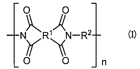
式(I)において、一般に、R1は、テトラカルボン酸二無水物由来の構造であり、R2はジアミン由来の構造である。
これらは単独あるいは2種以上混合して用いられる。
なかでも、吸湿膨張係数を低減させる観点から、3,3’,4,4’-ビフェニルテトラカルボン酸二無水物、2,3,3’,4’-ビフェニルテトラカルボン酸二無水物、2,3,2’,3’-ビフェニルテトラカルボン酸二無水物、ビス(3,4-ジカルボキシフェニル)エーテル二無水物が特に好ましい。
また、ピロメリット酸二無水物、メロファン酸二無水物、3,3’,4,4’-ビフェニルテトラカルボン酸二無水物、2,3,3’,4’-ビフェニルテトラカルボン酸二無水物、2,3,2’,3’-ビフェニルテトラカルボン酸二無水物、1,4,5,8-ナフタレンテトラカルボン酸二無水物などの剛直なテトラカルボン酸二無水物を用いると、ポリイミドの線熱膨張係数が小さくなるので好ましい。なかでも、線熱膨張係数と吸湿膨張係数とのバランスの観点から、3,3’,4,4’-ビフェニルテトラカルボン酸二無水物、2,3,3’,4’-ビフェニルテトラカルボン酸二無水物、2,3,2’,3’-ビフェニルテトラカルボン酸二無水物が特に好ましい。
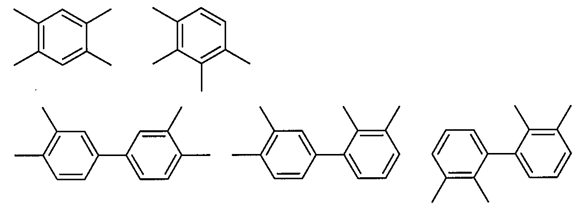
上記のような構造を有するポリイミドは、高耐熱性、低線熱膨張係数を示すポリイミドである。そのため、上記式で表わされる構造の含有量は上記式(I)中のR1のうち100モル%に近ければ近いほど好ましいが、少なくとも上記式(I)中のR1のうち33%以上含有すればよい。中でも、上記式で表わされる構造の含有量は上記式(I)中のR1のうち50モル%以上であることが好ましく、さらに70モル%以上であることが好ましい。
さらに目的に応じ、架橋点となるエチニル基、ベンゾシクロブテン-4’-イル基、ビニル基、アリル基、シアノ基、イソシアネート基、及びイソプロペニル基のいずれか1種または2種以上を、上記ジアミンの芳香環上水素原子の一部もしくは全てに置換基として導入しても使用することができる。
さらに、2つ以上の芳香族環が単結合により結合し、2つ以上のアミノ基がそれぞれ別々の芳香族環上に直接または置換基の一部として結合しているジアミンが挙げられ、例えば、下記式(II)により表されるものがある。具体例としては、ベンジジン等が挙げられる。
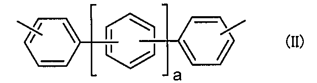
さらに、上記式(II)において、他のベンゼン環との結合に関与せず、ベンゼン環上のアミノ基が置換していない位置に置換基を有するジアミンも用いることができる。これら置換基は、1価の有機基であるがそれらは互いに結合していてもよい。具体例としては、2,2’-ジメチル-4,4’-ジアミノビフェニル、2,2’-ジトリフルオロメチル-4,4’-ジアミノビフェニル、3,3’-ジクロロ-4,4’-ジアミノビフェニル、3,3’-ジメトキシ-4,4’-ジアミノビフェニル、3,3’-ジメチル-4,4’-ジアミノビフェニル等が挙げられる。
また、芳香環の置換基としてフッ素を導入すると吸湿膨張係数を低減させることができる。しかしながら、フッ素を含むポリイミド前駆体、特にポリアミック酸は、塩基性水溶液に溶解しにくく、金属基材上に絶縁層を部分的に形成する場合には、絶縁層の加工の際に、アルコールなどの有機溶媒との混合溶液で現像する必要がある場合がある。
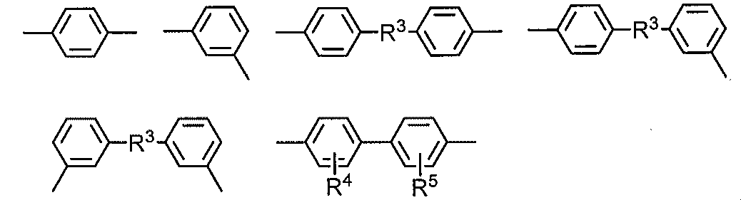
ポリイミドが上記式のいずれかの構造を含むと、これら剛直な骨格に由来し、低線熱膨張および低吸湿膨張を示す。さらには、市販で入手が容易であり、低コストであるというメリットもある。
上記のような構造を有する場合、ポリイミドの耐熱性が向上し、線熱膨張係数が小さくなる。そのため、上記式(I)中のR2のうち100モル%に近ければ近いほど好ましいが、上記式(I)中のR2のうち少なくとも33%以上含有すればよい。中でも上記式で表わされる構造の含有量は上記式(I)中のR2のうち50モル%以上であることが好ましく、さらに70モル%以上であることが好ましい。
なお、絶縁層がポリイミドを主成分とするとは、上述の特性を満たす程度に、絶縁層がポリイミドを含有することをいう。具体的には、絶縁層中のポリイミドの含有量が75質量%以上の場合をいい、好ましくは90質量%以上であり、特に絶縁層がポリイミドのみからなることが好ましい。絶縁層中のポリイミドの含有量が上記範囲であれば、本発明の目的を達成するのに十分な特性を示すことが可能であり、ポリイミドの含有量が多いほど、ポリイミド本来の耐熱性や絶縁性などの特性が良好となる。
絶縁層が金属基材上に部分的に形成されている場合には、中でも、図4(a)、(b)に例示するように、絶縁層3は、金属基材2の外縁部10を除いて形成されていることが好ましい。なお、図4(a)は上面図、図4(b)は図4(a)のA-A線断面図であり、図4(a)において粘着層および剥離層は省略されている。本発明の熱伝導性封止部材を用いて例えばEL素子を作製した場合、金属基材の全面に絶縁層が形成されており絶縁層の端面が露出していると、一般にポリイミドは吸水性が比較的高いため、製造時や駆動時に絶縁層の端面から水分が浸入するおそれがある。この水分によって、素子性能が劣化したり、絶縁層の寸法が変化したりする。そのため、金属基材の外縁部には絶縁層が形成されておらず、直接外気にポリイミドを含有する絶縁層が曝される部分をできる限り少なくすることが好ましいのである。
塗布方法としては、例えば、スピンコート法、ダイコート法、ディップコート法、バーコート法、グラビア印刷法、スクリーン印刷法などを用いることができる。
本発明における粘着層は、絶縁層上に形成され、耐熱性を有するものである。
なお、5%重量減少温度は、熱重量分析装置または示差熱天秤(例えばThermo Plus TG8120(リガク社製))を用い、窒素雰囲気下、10℃/分の昇温速度で昇温し、測定した値である。
なお、貯蔵弾性率は、動的粘弾性測定装置(例えば、RSA3 (TAインスツルメンツ社製)を用い、周波数1Hz、昇温速度5℃/分の条件で測定した値である。
なお、体積抵抗は、JIS K6911、JIS C2318、ASTM D257 などの規格に準拠する手法で測定することが可能である。
ポリイミド系樹脂としては、下記式(III)で表される繰り返し単位を含むことが好ましい。
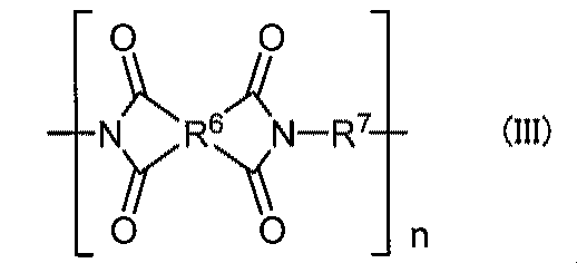
式(III)において、一般に、R6は、テトラカルボン酸二無水物由来の構造であり、R7はジアミン由来の構造である。
同様に、テトラカルボン酸二無水物についても、2つの酸無水物基が接続する部位の構造が芳香族であるものが芳香族酸二無水物、脂肪族であるものが脂肪族酸二無水物という。

(式(2)中、R11は4価の有機基であり、Y1~Y4は独立して水素または炭素数1~8の炭化水素基である。)
(式(3)中、X1は、アミノ基に脂肪族基または脂環基が直接結合している炭素数1~221の2価の有機基であり、その構造の一部に芳香族基、エーテル基、その他の置換基を含んでいてもよい。)
(式(4)中、X2は、アミノ基に芳香族環が直接結合している炭素数6~27の2価の有機基であり、その構造の一部に脂肪族基、脂環基、その他の置換基を含んでいてもよい。)
(式(5)中、Zは2価の有機基である。)
ここで、式(III)におけるR6は式(1)におけるR11であり、式(III)におけるR7は式(3)におけるX1または式(4)におけるX2である。
・工程(1):テトラカルボン酸成分と脂肪族ジアミンとを加熱反応させてポリイミド(A)を合成する工程
・工程(2):工程(1)で合成したポリイミド(A)と芳香族ジアミンとを加熱反応させてポリイミド(B)を合成する工程
・工程(3):工程(2)で合成したポリイミド(B)と2官能性の架橋剤とを配合して室温で混合し、熱硬化性ポリイミド樹脂組成物を製造する工程
・工程(4):工程(3)で得られた熱硬化性ポリイミド樹脂組成物を加熱硬化させて、ポリイミド系樹脂を得る工程

(式(7)中、n1はプロピレンオキシド単位の重合度である。)
(式(8)中、n2はエチレンオキシド単位の重合度である。)
(式(9)中、n3はブチレンオキシド単位の重合度である。)
上記式(5)のビスマレイミド化合物は以下のものが挙げられる。N,N’-(4,4’-ジフェニルメタン)ビスマレイミド、N,N’-(4,4’-ジフェニルオキシ)ビスマレイミド、N,N’-(4,4’-ジフェニルスルホン)ビスマレイミド、N,N’-p-フェニレンビスマレイミド、N,N’-m-フェニレンビスマレイミド、N,N’-2,4-トリレンビスマレイミド、N,N’-2,6-トリレンビスマレイミド、N,N’-エチレンビスマレイミド、N,N’-ヘキサメチレンビスマレイミド、N,N’-{4,4’-〔2,2’-ビス(4’’,4’’’-フェノキシフェニル)イソプロピリデン〕}ビスマレイミド、N,N’-{4,4’-〔2,2’-ビス(4’’,4’’’-フェノキシフェニル)ヘキサフルオロイソプロピリデン〕}ビスマレイミド、N,N’-〔4,4’-ビス(3,5-ジメチルフェニル)メタン〕ビスマレイミド、N,N’-〔4,4’-ビス(3,5-ジエチルフェニル)メタン〕ビスマレイミド、N,N’-〔4,4’-(3-メチル-5-エチルフェニル)メタン〕ビスマレイミド、N,N’-〔4,4’-ビス(3,5-ジイソプロピルフェニル)メタン〕ビスマレイミド、N,N’-(4,4’-ジシクロヘキシルメタン)ビスマレイミド、N,N’-p―キシリレンビスマレイミド、N,N’-m―キシリレンビスマレイミド、N,N’-(1,3-ジメチレンシクロヘキサン)ビスマレイミド、N,N’-(1,4-ジメチレンシクロヘキサン)ビスマレイミド等である。また、ポリオキシアルキレンジアミンの両末端が無水マレイン酸で封止されたビスマレイミド化合物を用いることもできる。例えば、ポリオキシエチレンジアミンの両末端が無水マレイン酸で封止されたビスマレイミド化合物、ポリオキシプロピレンジアミンの両末端が無水マレイン酸で封止されたビスマレイミド化合物、ポリオキシブチレンジアミンの両末端が無水マレイン酸で封止された化合物が挙げられる。この中で好ましいのは下記式(10)で表されるN,N’―(4,4’―ジフェニルメタン)ビスマレイミド、下記式(11)のN,N’-〔4,4’-ビス(3-メチル-5-エチルフェニル)メタン〕ビスマレイミドである。
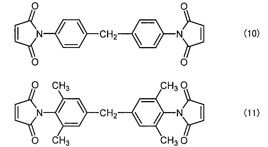
アクリル系樹脂からなる粘着剤には、通常、(メタ)アクリル酸アルキルエステルの重合体または他の共重合性モノマーとの共重合体が用いられる。(メタ)アクリル酸アルキルエステルのアルキルエステルとしては、例えば、メチルエステル、エチルエステル、ブチルエステル、2-エチルヘキシルエステル、オクチルエステル、イソノニルエステル等が挙げられる。また、他の共重合性モノマーとしては、(メタ)アクリル酸のヒドロキシヘキシルエステル(例えば、ヒドロキシエチルエステル、ヒドロキシブチルエステル、ヒドロキシヘキシルエステル等)、(メタ)アクリル酸グリシジルエステル、(メタ)アクリル酸、イタコン酸、無水マレイン酸、(メタ)アクリル酸アミド、(メタ)アクリル酸N-ヒドロキシメチルアミド、(メタ)アクリル酸アルキルアミノアルキルエステル(例えば、ジメチルアミノエチルメタクリレート等)、酢酸ビニル、スチレン、アクリロニトリル等が挙げられる。
また、粘着層中の上記架橋剤の配合量としては、粘着剤組成の0.2重量部~10重量部の範囲内であることが好ましい。配合量が上記範囲未満の場合、架橋密度が低く硬化が不十分となる場合がある。また、配合量が上記範囲を超えると、架橋密度が高くなり過ぎ、粘着力が維持できない場合がある。
これら成分に光重合開始剤(例えば、イルガキュア184、イルガキュア651、イルガキュア369、イルガキュア1800(チバ・スペシャリティ・ケミカルズ社)、Chivacure TPO、Chivacure 107、Chivacure 173、Chivacure 1256(チャイテック社)等)を0.001重量部~5.0重量部程度添加し用いられる。
また、放射線硬化成分を含む粘着剤に光重合開始剤の代わりに熱重合開始剤を用いることにより、熱硬化型粘着剤として用いることもできる。
ポリエステル系樹脂からなる粘着剤には、ポリエステル樹脂として、酸成分とポリオール成分とを重縮合させた共重合ポリエステルをその主成分としたものが用いられる。重縮合反応は直接エステル化法やエステル交換法等の一般的な公知の反応によって行われる。
ポリエステル系樹脂の酸成分としては、テレフタル酸、イソフタル酸、無水フタル酸、α-ナフタレンジカルボン酸、5-ナトリウムスルホイソフタル酸、5-カリウムスルホイソフタル酸およびこれらのエステル類、ピメリン酸、スベリン酸、アゼライン酸、セバシン酸、ウンデシレン酸、ドデカンジカルボン酸およびこれらのエステル類等の脂肪族ジカルボン酸や1,4シクロヘキサヒドロ無水フタル酸等の脂環式ジカルボン酸が用いられる。中でも、テレフタル酸、イソフタル酸およびセバシン酸が好ましい。これらは単独または2種以上を混合して使用することができる。
また、ポリエステル系樹脂のアルコール成分としては、1,2-プロピレングリコール、ポリテトラメチレンオキシドグリコール、エチレングリコール、1,3-プロピレングリコール、1,3-ブタンジオール、1,4-ブタンジオール、1,5-ペンタンジオール、1,6-ヘキサンジオール、1,8-オクタンジオール、1,9-ノナンジオール、ネオペンチルグリコール、3-メチルペンタンジオール、2,2,3-トリメチルペンタンジオール、ジエチレングリコール、トリエチレングリコール、ジプロピレングリコール等の脂肪族グリコール、1,4-シクロヘキサンジオール、1,4-シクロヘキサンジメタノール等の脂環式グリコール、およびビスフェノールAなどの芳香族グリコールが用いられる。中でも、1,2-プロピレングリコール、ポリテトラメチレンオキシドグリコール、エチレングリコールおよび1,4-ブタンジオールが好ましい。これらは単独または2種以上を混合または重合して使用することができる。
シリコーン系樹脂からなる粘着剤は、シリコーン系樹脂として、シリコーン共重合体を含有する。シリコーン共重合体としては、ビニルシリル基(Si-CH=CH2基)やハイドロシリル基(Si-H基)などを有する付加重合型シリコーン共重合体が挙げられる。付加重合型シリコーン共重合体としては、例えば、SD4560、SD4570、SD4580、SD4584、SD4585、SD4585、SD4592、BY24-740(東レ・ダウコーニング製)、X-40-3068、X-40-3102、X-40-3103、X-40-3104(信越化学製)が使用される。なお、特にこれらに限定されるものではない。
粘着層に用いられる樹脂組成物を後硬化させる場合には、樹脂組成物が、粘着層の形成過程での脱水ベークの際に硬化反応が開始するような添加剤を含有していることが好ましい。このような添加剤としては、例えば熱塩基発生剤または光塩基発生剤が挙げられる。
なお、吸湿剤については、上記絶縁層の項に記載したものと同様であるので、ここでの説明は省略する。
粘着層が金属基材上に部分的に形成されている場合であって、粘着層がポリイミド系樹脂からなり吸湿剤を含有していない場合には、図5に例示するように、粘着層4は金属基材2の外縁部10を除いて形成されていることが好ましい。本発明の熱伝導性封止部材を用いて例えばEL素子を作製した場合、金属基材の全面に粘着層が形成されており粘着層の端面が露出していると、一般にポリイミド系樹脂は吸水性を示すため、製造時や駆動時に粘着層の端面から水分が浸入するおそれがある。この水分によって、素子性能が劣化したり、粘着層の寸法が変化したりする。そのため、粘着層がポリイミド系樹脂からなり吸湿剤を含有していない場合には、金属基材の外縁部には粘着層が形成されていないことが好ましいのである。
また、粘着層を金属基材の外縁部を除いて形成する場合、その形成方法としては、印刷法、フォトリソグラフィー法、レーザーで直接加工する方法、加工用シートを型抜きする方法などを用いることができる。加工用シートを型抜きする方法の場合、剥離シート上に粘着層が形成された加工用シートを型抜きし、粘着層上に剥離層を貼付し、粘着層から剥離シートを剥がすことで、剥離層と金属基材の外縁部を除いて形成することが可能な粘着層との積層体を得ることができる。この場合に用いられる剥離シートとしては一般的なものを使用することができる。
本発明における金属基材は、上記の絶縁層および粘着層を支持するものである。
凹凸の形成方法としては、例えば金属基材の表面に直接、エンボス加工、エッチング加工、サンドブラスト加工、フロスト加工、スタンプ加工などの加工を施す方法、フォトレジスト等を用いて凹凸パターンを形成する方法、めっき方法、箔状や板状等の金属層と表面に凹凸を有する金属層とを貼り合わせる方法が挙げられる。エンボス加工の場合、例えば表面に凹凸を有する圧延ロールを用いてもよい。エッチング加工の場合、金属基材の種類に応じて薬剤が選択される。箔状や板状等の金属層と表面に凹凸を有する金属層とを貼り合わせる方法の場合、例えば、ロウ付け、溶接、半田等により金属層同士を接合する、あるいは、エポキシ樹脂等の接着剤を介して金属層同士を貼り合わせることができる。この場合、箔状や板状等の金属層と表面に凹凸を有する金属層とは、同じ金属材料で構成されていてもよく、異なる金属材料で構成されていてもよい。
中でも、コスト面から、エンボス加工、エッチング加工が好ましく用いられる。
本発明においては、上記粘着層上に剥離層が形成されていることが好ましい。本発明の熱伝導性封止部材の取り扱いが容易になるからである。
ガスバリア層に用いられる無機材料としては、例えば、無機酸化物、無機酸化窒化物、無機窒化物、金属を挙げることができる。これらは1種または2種以上を組み合わせて使用することができる。無機酸化物としては、酸化ケイ素、酸化アルミニウム、酸化マグネシウム、酸化チタン、酸化スズ、酸化インジウム合金が挙げられる。無機酸化窒化物としては、酸化窒化ケイ素が挙げられる。無機窒化物としては、窒化ケイ素、窒化アルミニウム、窒化チタンが挙げられる。金属としては、アルミニウム、銀、錫、クロム、ニッケル、チタンが挙げられる。無機材料として窒化物を含む材料を利用すると、粘着層に対して離型性を示す場合が多く、ガスバリア性と離型性を兼ね備えた材料として使用できる。
一方、ガスバリア層に用いられる有機材料としては、例えば、エポキシ/シリケート、ポリビニルアルコール(PVA)、エチレン-ビニルアルコール共重合体(EVOH)を挙げることができる。PVAおよびEVOHは単独または混合物で使用することができる。
ガスバリア層は、単層であってもよく複数層が積層されたものであってもよい。
また、共押し出しフィルムの場合、材料としては、上記基材フィルムに用いられる樹脂に有機物または無機物の微粒子や粉体を混合したコンポジット材料などを使用することができる。
本発明においては、図7に例示するように、金属基材2の外縁部10に防湿部6が形成されていてもよい。防湿部が形成されていることによって、外部からの水分の浸入を防ぐことができるからである。また、本発明の熱伝導性封止部材を用いてEL素子を封止する際には、図8に例示するように、熱伝導性封止部材が剥離層を有さない場合には熱伝導性封止部材を直接、あるいは熱伝導性封止部材が剥離層を有する場合には熱伝導性封止部材から剥離層を剥がして、透明電極層22とEL層23と背面電極層24とが積層された透明基板21に貼り付けるだけでEL素子20の封止が可能であり、煩雑な工程を要することなく簡便な方法でEL素子を封止することができる。
吸湿剤の含有量は、特に限定されるものではないが、吸湿剤と樹脂の合計量100質量部に対して、5質量部~80質量部の範囲内であることが好ましく、より好ましくは5質量部~60質量部の範囲内、さらに好ましくは5質量部~50質量部の範囲内である。
防湿部の形成方法としては、樹脂組成物を塗布する方法を用いることができる。樹脂組成物を塗布する際には、金属基材上に塗布してもよく剥離層上に塗布してもよい。また、後述するように加工用シートを型抜きする方法を採用する場合には、剥離シート上に樹脂組成物を塗布する。塗布方法としては、所定の部分に塗布することができる方法であれば特に限定されるものではなく、例えば、グラビア印刷法、スクリーン印刷法、ティスペンサー法などを用いることができる。
また、防湿部を金属基材の外縁部に形成するに際しては、印刷法、フォトリソグラフィー法、レーザーで直接加工する方法、加工用シートを型抜きする方法などを用いることができる。加工用シートを型抜きする方法の場合、剥離シート上に防湿部が形成された加工用シートを型抜きし、防湿部上に剥離層を貼付し、防湿部から剥離シートを剥がすことで、剥離層上に防湿部が形成された積層体を得ることができる。この場合に用いられる剥離シートとしては一般的なものを使用することができる。
本発明においては、金属基材と絶縁層との間に中間層が形成されていてもよい。例えば、金属基材および絶縁層の間に、金属基材を構成する金属が酸化された酸化膜からなる中間層が形成されていてもよい。これにより、金属基材と絶縁層との密着性を高めることができる。この酸化膜は、金属基材表面が酸化されることで形成される。
また、金属基材の絶縁層が形成されている面とは反対側の面にも上記酸化膜が形成されていてもよい。
本発明の熱伝導性封止部材は、水分の浸入防止および放熱機能の付与が必要となる素子に用いられる。具体的には、EL素子、有機薄膜太陽電池、固体撮像素子などの半導体素子が挙げられる。中でも、照明用途のEL素子に好適である。
次に、本発明のEL素子について説明する。
本発明のEL素子は、透明基板と、上記透明基板上に形成された透明電極層と、上記透明電極層上に形成され、少なくとも発光層を含むEL層と、上記EL層上に形成された背面電極層と、上記透明電極層、上記EL層、および上記背面電極層を覆うように形成された熱伝導性封止部材とを有するEL素子であって、上記熱伝導性封止部材が、金属基材と、上記金属基材上に形成され、熱伝導性を有し、少なくともポリイミドを含有する絶縁層と、上記絶縁層上に形成され、耐熱性を有する粘着層とを有し、上記粘着層が上記透明電極層、上記EL層、および上記背面電極層を覆うように上記透明基板に接着されていることを特徴とするものである。
図2は、本発明のEL素子の一例を示す概略断面図である。図2に例示するEL素子20は、透明基板21と、透明基板21上に形成された透明電極層22と、透明電極層22上に形成され、少なくとも発光層を有するEL層23と、EL層23上に形成された背面電極層24と、透明電極層22、EL層23および背面電極層24を覆うように形成された熱伝導性封止部材1aと、透明基板21上に熱伝導性封止部材1aの外周を囲むように形成された封止樹脂部25とを備えている。熱伝導性封止部材1aは、金属基材2と、金属基材2上に形成され、熱伝導性を有し、少なくともポリイミドを含有する絶縁層3と、絶縁層3上に形成され、耐熱性を有する粘着層4とを有している。そして、熱伝導性封止部材1aの粘着層4が透明電極層22、EL層23および背面電極層24を覆うように透明基板21に接着されている。図2に例示するEL素子20は、例えば図1に示す熱伝導性封止部材1aあるいは図3に示す熱伝導性封止部材1bを用いて得ることができる。
また本発明によれば、熱伝導性封止部材の粘着層をEL素子を支持する透明基板に貼り付けることで、熱伝導性封止部材と、透明電極層、EL層および背面電極層が積層された透明基板とを密着させることができ、煩雑な工程を要することなく簡便な方法でEL素子を封止することが可能である。また本発明においては、室温で熱伝導性封止部材の粘着層をEL素子を支持する透明基板に貼り付けることができるので、熱に弱いEL素子の封止に有利であり、取り扱いが容易であるという利点も有する。
さらに本発明によれば、発熱による絶縁層および粘着層の劣化を抑制することもできる。
本発明におけるEL層は、透明電極層上に形成され、少なくとも発光層を含むものである。
EL層を構成する発光層は、有機発光層であってもよく、無機発光層であってもよい。有機発光層の場合には有機EL素子となり、無機発光層の場合には無機EL素子となる。中でも、発光層は有機発光層であることが好ましい。有機発光層は無機発光層よりも発熱による劣化が顕著であるからである。
以下、発光層が有機発光層である場合について説明する。
発光層が有機発光層である場合、EL層は、少なくとも有機発光層を含む1層もしくは複数層の有機層を有するものである。すなわち、EL層とは、少なくとも有機発光層を含む層であり、その層構成が有機層1層以上の層をいう。通常、塗布法でEL層を形成する場合は、溶媒との関係で多数の層を積層することが困難であることから、EL層は1層もしくは2層の有機層を有する場合が多いが、溶媒への溶解性が異なるように有機材料を工夫したり、真空蒸着法を組み合わせたりすることにより、さらに多数層とすることも可能である。
このようにEL層は種々の層を積層した積層構造を有することが多く、積層構造としては多くの種類がある。
本発明における透明電極層は、透明基板上に形成されるものである。
透明電極層の材料としては、透明電極を形成可能な導電性材料であれば特に限定されるものではなく、例えば、酸化インジウム錫(ITO)、酸化インジウム亜鉛(IZO)、酸化錫、酸化亜鉛、酸化インジウム、酸化アルミニウム亜鉛(AZO)等の導電性酸化物を用いることができる。
透明電極層の形成方法および厚みとしては、一般的なEL素子における電極と同様とすることができる。
本発明における背面電極層は、EL層上に形成されるものである。
背面電極層は透明性を有していてもよく有さなくてもよい。中でも、背面電極層上に白色反射層が形成されている場合には、背面電極層は透明性を有していることが好ましい。EL層からの発光を白色反射層で効率良く反射することができるからである。
本発明に用いられる透明基板は、透明電極層、EL層および背面電極層を支持するものである。
透明基板の材料としては、例えば、石英、ガラス等の無機材料;ポリカーボネート(PC)、ポリエチレンテレフタレート(PET)、ポリブチレンテレフタレート(PBT)、ポリフェニレンスルフィド(PPS)、ポリイミド(PI)、ポリアミドイミド(PAI)、ポリエーテルスルホン(PES)、ポリエーテルイミド(PEI)、ポリエーテルエーテルケトン(PEEK)等の高分子材料;およびこれらの高分子材料に無機微粒子や無機物の繊維などを添加したものを挙げることができる。
透明基板の厚みとしては、透明基板の材料およびEL素子の用途により適宜選択される。具体的に、0.005mm~5mm程度である。
本発明においては、透明基板上に熱伝導性封止部材の外周を囲むように封止樹脂部が形成されていてもよい。封止樹脂部が形成されていることによって、外部からの水分の浸入を防ぐことができるからである。
本発明においては、図12に例示するように、背面電極層24と熱伝導性封止部材1aの粘着層4との間に白色反射層26が形成されていてもよい。EL層からの発光を白色反射層で拡散反射することができ、干渉効果により発生する発光色の角度依存性を緩和することができるからである。
白色顔料としては、例えば、酸化カルシウム、硫酸バリウム、酸化亜鉛、ステアリン酸バリウム、銀フレーク、ケイ酸塩類、アルミナ、酸化ジルコニウム、ジルコニウム硫酸ソーダ、カオリン、雲母、二酸化チタンなどが挙げられる。また、スチレンなどからなる非造膜性のポリマー粒子なども使用することができる。これらは、単独で用いてもよく混合して用いてもよい。中でも、二酸化チタンが好ましく用いられる。
また、バインダーとしては、例えば、アルカリ浸透性の高分子マトリックスを挙げることができ、具体的には、ゼラチン、ポリビニルアルコールや、ヒドロキシエチルセルロース、カルボキシルメチルセルロースなどのセルロース誘導体を挙げることができる。
白色顔料:バインダーの質量比は、例えば、1:1~20:1とすることができる。
本発明のEL素子は、透明電極層とEL層と背面電極層とが積層された透明基板上に熱伝導性封止部材を貼付することにより得られる。熱伝導性封止部材が剥離層を有する場合には、剥離層を剥がした後に、貼付する。
熱伝導性封止部材を貼付する方法としては、透明電極層、EL層および背面電極層が積層された透明基板と、熱伝導性封止部材の粘着層との間に気泡が入らないように、熱伝導性封止部材を貼付することができる方法であれば特に限定されるものではなく、熱伝導性封止部材の形態によって適宜選択される。雰囲気としては、大気中であってもよく真空中であってもよい。
[製造例1]
4,4’-ジアミノジフェニルエーテル(ODA) 4.0g(20mmol)とパラフェニレンジアミン(PPD) 8.65g(80mmol)とを500mlのセパラブルフラスコに投入し、200gの脱水されたN-メチル-2-ピロリドン(NMP)に溶解させ、窒素気流下、オイルバスによって液温が50℃になるように熱電対でモニターし加熱しながら撹拌した。それらが完全に溶解したことを確認した後、そこへ、30分かけて3,3’,4,4’-ビフェニルテトラカルボン酸二無水物(BPDA) 29.1g(99mmol)を少しずつ添加し、添加終了後、50℃で5時間撹拌した。その後室温まで冷却し、ポリイミド前駆体溶液1を得た。
反応温度および溶液の濃度が、17重量%~19重量%になるようにNMPの量を調整した以外は、製造例1と同様の方法で下記の表1に示す配合比でポリイミド前駆体溶液2~12、15~17およびポリイミド前駆体溶液Z(比較例)を合成した。
酸二無水物としては、3,3’,4,4’-ビフェニルテトラカルボン酸二無水物(BPDA)、ピロメリット酸二無水物(PMDA)、p-フェニレンビストリメリット酸モノエステル酸二無水物(TAHQ)、p-ビフェニレンビストリメリット酸モノエステル酸二無水物(BPTME)を用いた。ジアミンとしては、4,4’-ジアミノジフェニルエーテル(ODA)、パラフェニレンジアミン(PPD)、1,4-Bis(4-aminophenoxy)benzene(4APB)、2,2'-Dimethyl-4,4'-diaminobiphenyl(TBHG)、2,2'-Bis(trifluoromethyl)-4,4'-diaminobiphenyl(TFMB)の1種または2種を用いた。

感光性ポリイミドとするために、上記ポリイミド前駆体溶液1に{[(4,5-dimethoxy-2-nitrobenzyl) oxy]carbonyl} 2,6-dimethyl piperidine (DNCDP)を溶液の固形分の15重量%添加し、感光性ポリイミド前駆体溶液1とした。
[製造例14]
感光性ポリイミドとするために、上記ポリイミド前駆体溶液1に、2-ヒドロキシ-5-メトキシ-桂皮酸とピペリジンとから合成したアミド化合物(HMCP)を溶液の固形分の10重量%添加し、感光性ポリイミド前駆体溶液2とした。

上記ポリイミド前駆体溶液1~12、15~17およびポリイミド前駆体溶液Zを、ガラス上に貼り付けた耐熱フィルム(ユーピレックスS 50S:宇部興産(株)製)上に塗布し、80℃のホットプレート上で10分乾燥させた後、耐熱フィルムから剥離し、膜厚15μm~20μmのフィルムを得た。その後、そのフィルムを金属製の枠に固定し、窒素雰囲気下、350℃、1時間熱処理し(昇温速度 10℃/分、自然放冷)、膜厚9μm~15μmのポリイミド1~12、15~17およびポリイミドZ(比較例)のフィルムを得た。
また、上記感光性ポリイミド前駆体溶液1および2を、ガラス上に貼り付けた耐熱フィルム(ユーピレックスS 50S:宇部興産(株)製)上に塗布し、100℃のホットプレート上で10分乾燥させた後、高圧水銀灯により365nmの波長の照度換算で2000mJ/cm2露光後、ホットプレート上で170℃、10分加熱した後、耐熱フィルムより剥離し、膜厚10μmのフィルムを得た。その後、そのフィルムを金属製の枠に固定し、窒素雰囲気下、350℃、1時間熱処理し(昇温速度 10℃/分、自然放冷)、膜厚6μmの感光性ポリイミド1および感光性ポリイミド2のフィルムを得た。
上記の手法により作製したフィルムを幅5mm×長さ20mmに切断し、評価サンプルとして用いた。線熱膨張係数は、熱機械的分析装置Thermo Plus TMA8310(リガク社製)によって測定した。測定条件は、評価サンプルの観測長を15mm、昇温速度を10℃/min、評価サンプルの断面積当たりの加重が同じになるように引張り加重を1g/25000μm2とし、100℃~200℃の範囲の平均の線熱膨張係数を線熱膨張係数(C.T.E.)とした。
上記の手法により作製したフィルムを幅5mm×長さ20mmに切断し、評価サンプルとして用いた。吸湿膨張係数は、湿度可変機械的分析装置Thermo Plus TMA8310改(リガク社製)によって測定した。温度を25℃で一定とし、まず、湿度を15%RHの環境下でサンプルが安定となった状態とし、概ね30分~2時間その状態を保持した後、測定部位の湿度を20%RHとし、さらにサンプルが安定になるまで30分~2時間その状態を保持した。その後、湿度を50%Rhに変化させ、それが安定となった際のサンプル長と20%RHで安定となった状態でのサンプル長との違いを、湿度の変化(この場合、50-20の30)で割り、その値をサンプル長で割った値を吸湿膨張係数(C.H.E.)とした。評価サンプルの断面積当たりの加重が同じになるように引張り加重を1g/25000μm2とした。
厚さ18μmのSUS304-HTA箔(東洋精箔製)上に、上記のポリイミド前駆体溶液1~12、15~17およびZ、ならびに感光性ポリイミド前駆体溶液1,2を用い、イミド化後の膜厚が10μm±1μmになるように線熱膨張係数評価のサンプル作成と同様のプロセス条件で、ポリイミド1~12およびZのポリイミド膜、ならびに感光性ポリイミド1,2のポリイミド膜を形成した。その後、SUS304箔およびポリイミド膜の積層体を幅10mm×長さ50mmに切断し、基板反り評価用のサンプルとした。
同様にこのサンプルを、SUS板表面にサンプルの短辺の片方のみをカプトンテープにより固定し、23℃85%Rhの状態の恒温恒湿槽に1時間静置したときの、サンプルの反対側の短辺のSUS板からの距離を測定した。そのときの距離が、0mm以上0.5mm以下のサンプルを○、0.5mm超1.0mm以下のサンプルを△、1.0mm超のサンプルを×と判断した。
これらの評価結果を以下に示す。
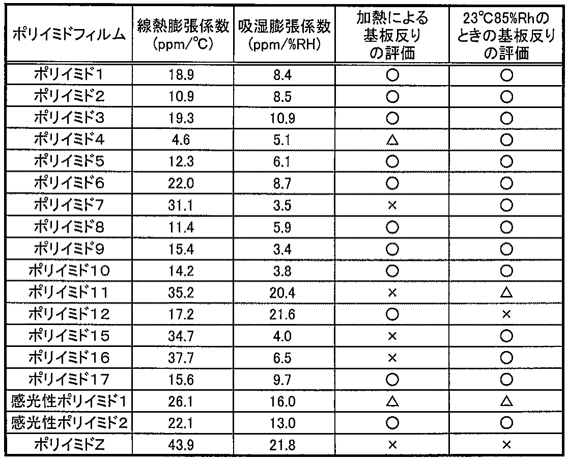
また、表2より、ポリイミド膜の吸湿膨張係数が小さいほど高湿環境下での積層体の反りが小さいことがわかる。
[製造例1](ポリイミド系粘着剤)
まず、熱硬化性ポリイミド樹脂組成物を調製するために、次のようにポリイミド13を調製し、さらにポリイミド14を調製した。
1,2,4,5-シクロヘキサンテトラカルボン酸二無水物20.35g(0.090モル)、ポリオキシプロピレンジアミン(三井化学ファイン社製、ジェファーミンD2000)118.81g(0.060モル)、N-メチル-2-ピロリドン91.50gを窒素気流下で加え合わせ、200℃に昇温して3時間イミド化反応を行い、ディーンスターク装置を用いて生成水を分離した。反応後、水の留出がないことを確認し、室温(23℃)まで放冷し反応物(ポリイミド13)を得た。ポリイミド13の生成の有無は、IRスペクトルを確認して、ν(C=O)1770、1706cm-1のイミド環の特性吸収を確認することで判定した。次に、ポリイミド13に、4,4’―ジアミノジフェニルエーテル12.08g(0.060モル)、N-メチル-2-ピロリドン9.74gを加え、200℃に昇温して3時間イミド化反応を行い、ディーンスターク装置で生成水を分離した。イミド化反応後、水の留出が止まったのを確認し、反応生成物溶液を室温まで放冷し、反応生成物溶液中に反応物(ポリイミド14)を得た。ポリイミド14の生成有無は、IRスペクトルから確認した。
上記ポリイミド14を用いて、熱硬化性ポリイミド樹脂組成物1~6を調製した。そして、熱硬化性ポリイミド樹脂組成物1~6を用いた硬化物に基づき、その耐熱性とゴム弾性とガラス転移温度とを測定した。
まず、窒素気流下、ポリイミド14に架橋剤のN,N’-(4,4’-ジフェニルメタン)ビスマレイミドを混合するとともに、これに酸化防止剤を下記表3に示す配合量(重量比)で混合させて混合物を得た。次いで、混合物を、N,N’-ジメチルアセトアミド(DMAc)と1,3-ジオキソランとの混合液(混合液の混合比率は、体積比率でDMAc:1,3-ジオキソラン=50%:50%とした。)を用いて、固形分濃度(重量%)が25%となるように希釈し、室温で1時間攪拌し完全に溶解させ、熱硬化性ポリイミド樹脂組成物1~6を得た。
酸化防止剤A1:ヒンダートフェノール系酸化防止剤(チバ・ジャパン株式会社製、IRGANOX1010)
酸化防止剤A2:ヒンダートフェノール系酸化防止剤(チバ・ジャパン株式会社製、IRGANOX1098)
酸化防止剤A3:ヒンダートフェノール系酸化防止剤(チバ・ジャパン株式会社製、IRGANOX1010)と1,2,3-ベンゾトリアゾールとの併用(配合比率は、ヒンダートフェノール系酸化防止剤:1,2,3-ベンゾトリアゾール=2(重量部):1(重量部))

粘着剤(主剤)(綜研化学(株)製、商品名;SK-2094)100質量部、架橋剤(綜研化学(株)製、商品名;E-5XM)1質量部を混合することにより粘着性樹脂組成物1を調製した。粘着性樹脂組成物1を、乾燥膜厚が25μm程度になるように塗工し、乾燥後、室温で7日間、エージングすることで粘着層を得た。硬化物のガラス転移温度は、損失正接(tanδ)のピークトップの値に基づくと(DMA法に基づくと)、-4℃であり、25℃における貯蔵弾性率は、1.3×10⁵Paであった。また、粘着層の5%重量減少温度は、320℃であった。
粘着剤(主剤)(日本合成化学(株)製、商品名;ポリエスターNP-201、固形分50wt%)100質量部、架橋剤(日本ポリウレタン工業(株)製、商品名;コロネートL)5質量部を混合することにより粘着性樹脂組成物2を調製した。粘着性樹脂組成物2を、乾燥膜厚が25μm程度になるように塗工し、乾燥後、室温で7日間、エージングすることで粘着層を得た。硬化物のガラス転移温度は、損失正接(tanδ)のピークトップの値に基づくと(DMA法に基づくと)、-20℃であり、25℃における貯蔵弾性率は、8.0×10⁵Paであった。また、粘着層の5%重量減少温度は、280℃であった。
粘着剤(主剤)(東レ・ダウ コーニング・シリコーン(株)製、商品名;SD4570、固形分60wt%)100質量部、硬化剤(東レ・ダウ コーニング・シリコーン(株)製、商品名;SRX212)0.9質量部を混合することにより粘着性樹脂組成物3を調製した。粘着性樹脂組成物3を、乾燥膜厚が25μm程度になるように塗工し、100℃で3分間加熱することにより粘着層を得た。硬化物のガラス転移温度は、損失正接(tanδ)のピークトップの値に基づくと(DMA法に基づくと)、-15℃であり、25℃における貯蔵弾性率は、1.2×10⁵Paであった。また、粘着剤層の5%重量減少温度は、340℃であった。
[製造例]
(1)絶縁層の形成
(絶縁層の形成1(絶縁層ベタ))
15cm角に切り出した厚さ18μmのSUS304-HTA箔(東洋精箔製)上に、上記ポリイミド前駆体溶液1~10をダイコーターでコーティングし、80℃のオーブン中、大気下で60分乾燥させた後、窒素雰囲気下、350℃、1時間熱処理し(昇温速度 10℃/分、自然放冷)、膜厚6μm~12μmのポリイミド1~10のポリイミド膜を形成し、積層体1~10を得た。
積層体1~10のうち、積層体1,2,3,5,6,8,9,10は、温度や湿度環境の変化に対しても安定して平坦性が確保されていた。一方、積層体4,7は、反りが目立った。
15cm角に切り出した厚さ18μmのSUS304-HTA箔(東洋精箔製)上に、上記ポリイミド前駆体溶液1をダイコーターでコーティングし、80℃のオーブン中、大気下で60分乾燥させた。その後、ポリイミド前駆体膜上に、SUS箔の外縁部より15mm幅でレジストが除去されるように、レジスト製版し現像と同時にポリイミド前駆体膜を現像し、その後、レジストパターンを剥離したのち、窒素雰囲気下、350℃、1時間熱処理し(昇温速度 10℃/分、自然放冷)、外縁部の絶縁層が除去された積層体1Pを得た。
積層体1Pは、温度や湿度環境の変化に対しても安定して平坦性が確保されていた。
上記積層体10のポリイミド膜上に、SUS箔の外縁部より15mm幅でレジストが除去されるように、レジストパターンを形成した。ポリイミド膜が露出している部分を、ポリイミドエッチング液TPE-3000(東レエンジニアリング製)を用いて除去後、レジストパターンを剥離し、外縁部の絶縁層が除去された積層体10Pを得た。
積層体10Pは、温度や湿度環境の変化に対しても安定して平坦性が確保されていた。
15cm角に切り出した厚さ18μmのSUS304-HTA箔(東洋精箔製)上に、上記感光性ポリイミド前駆体溶液1および2をそれぞれダイコーターでコーティングし、80℃のオーブン中、大気下で60分乾燥させた。その後、SUS箔の外縁部より15mm幅で(紫外線が照射されないように)マスクし、高圧水銀灯により365nmの波長の照度換算で2000mJ/cm2露光後、ホットプレート上で170℃、10分加熱した後、窒素雰囲気下、350℃、1時間熱処理し(昇温速度 10℃/分、自然放冷)、膜厚3μmの感光性ポリイミド1および感光性ポリイミド2のポリイミド膜を形成し、積層体11および12を得た。
積層体11および12は、温度や湿度環境の変化に対しても安定して平坦性が確保されていた。
(金属基材の作製1)
まず、上記積層体1の両面にドライフィルムレジストをラミネートした。次いで、積層体1のSUS箔側から200μm幅のラインアンドスペース(L/S)で筋状にレジストが除去されるように露光し、積層体1の絶縁層側から全面露光した後、レジスト製版を行った。その後、塩化第二鉄溶液を用いて、レジストの開口部にてSUS箔の厚みが9μm残存するようにSUS箔をハーフエッチングした後、レジストパターンを剥離することにより、SUS箔が200μm幅でハーフエッチングされた積層体1Hを得た。
まず、上記積層体1の両面にドライフィルムレジストをラミネートした。次いで、積層体1のSUS箔側から50μm角のラインアンドスペース(L/S)で等間隔にレジストが除去されるように露光し、積層体1の絶縁層側から全面露光した後、レジスト製版を行った。その後、塩化第二鉄溶液を用いて、レジストの開口部にてSUS箔の厚みが9μm残存するようにSUS箔をハーフエッチングした後、レジストパターンを剥離することにより、SUS箔が50μm角でハーフエッチングされた積層体1H′を得た。
(粘着層の形成1(絶縁層ベタ/粘着層ベタ))
上記積層体1,2,3,5,6,8,9,10に対して、上記熱硬化性ポリイミド樹脂組成物1~6を、適宜DMAc:1,3-ジオキソラン=50%:50%の混合溶液で希釈し、ダイコート法により塗布し、熱処理後、2μmの膜厚になるように大気中200℃で30分加熱し、粘着層を形成し、熱伝導性封止部材1-1、1-2、1-3、1-4、1-5、1-6、2-1、2-2、2-3、2-4、2-5、2-6、3-1、3-2、3-3、3-4、3-5、3-6、5-1、5-2、5-3、5-4、5-5、5-6、6-1、6-2、6-3、6-4、6-5、6-6、8-1、8-2、8-3、8-4、8-5、8-6、9-1、9-2、9-3、9-4、9-5、9-6、10-1、10-2、10-3、10-4、10-5、10-6とした。
また、上記積層体1H,1H′に対して、上記熱硬化性ポリイミド樹脂組成物4を、適宜DMAc:1,3-ジオキソラン=50%:50%の混合溶液で希釈し、ダイコート法により塗布し、熱処理後、2μmの膜厚になるように大気中200℃で30分加熱し、粘着層を形成し、熱伝導性封止部材1H-4、1H′-4とした。
これらの熱伝導性封止部材に、ポリエチレンテレフタラートフィルム上にバリア層が蒸着されたバリアフィルムを、バリア層が粘着層と密着するように貼り付けた。
上述の熱伝導性封止部材はいずれも、温度や湿度環境の変化に対しても安定して平坦性が確保されていた。
上記積層体1P、積層体10P、積層体11および12について、上記熱硬化性ポリイミド樹脂組成物2、4および6を、適宜DMAc:1,3-ジオキソラン=50%:50%の混合溶液で希釈し、ダイコート法により塗布し、熱処理後、2μmの膜厚になるように大気中200℃で30分加熱し、粘着層を形成し、熱伝導性封止部材1P-2、1P-4、1P-6、10P-2、10P-4、10P-6、11-2、11-4、11-6、12-2、12-4、12-6とした。
これらの熱伝導性封止部材に、ポリエチレンテレフタラートフィルム上にバリア層が蒸着されたバリアフィルムを、バリア層が粘着層と密着するように貼り付けた。
上述の熱伝導性封止部材はいずれも、温度や湿度環境の変化に対しても安定して平坦性が確保されていた。
ポリエチレンテレフタラート製の剥離フィルム上に、乾燥後の厚みが2μmになるように上記熱硬化性ポリイミド樹脂組成物2、4および6を、バーコートにより塗布し、大気中オーブンにより80℃、30分の条件で乾燥させた。そのフィルムを、上記積層体1P、積層体10P、積層体11および12における絶縁層と同じ面積に切り出し、積層体1P、積層体10P、積層体11および12の絶縁層に重なるように貼り付け、剥離フィルムを剥がし、大気中200℃で30分加熱処理し、熱伝導性封止部材1P-2P、1P-4P、1P-6P、10P-2P、10P-4P、10P-6P、11-2P、11-4P、11-6P、12-2P、12-4P、12-6Pとした。
これらの熱伝導性封止部材に、ポリエチレンテレフタラートフィルム上にバリア層が蒸着されたバリアフィルムを、バリア層が粘着層と密着するように貼り付けた。
上述の熱伝導性封止部材はいずれも、温度や湿度環境の変化に対しても安定して平坦性が確保されていた。
上記積層体1に対して、上記粘着性樹脂組成物1を、エージング後の膜厚が2μm程度になるようにバーコートにより塗工し、乾燥後、室温で7日間、エージングすることで粘着層を形成した後、大気中150℃で60分加熱することにより、熱伝導性封止部材1-1′を得た。
上記積層体1に対して、上記粘着性樹脂組成物2を、エージング後の膜厚が2μm程度になるようにバーコートにより塗工し、乾燥後、室温で7日間、エージングすることで粘着層を形成した後、大気中150℃で60分加熱することにより、熱伝導性封止部材1-2′を得た。
上記積層体1に対して、上記粘着性樹脂組成物3を、エージング後の膜厚が2μm程度になるようにバーコートにより塗工し、100℃で3分間加熱することにより乾燥することで粘着層を形成した後、大気中200℃で30分加熱することにより、熱伝導性封止部材1-3′を得た。
(防湿部の形成1(絶縁層パターン/粘着層パターン/一重の防湿部))
上記積層体1P-4Pの粘着層上に、この粘着層と同じ大きさの剥離フィルムを貼り付けた。次いで、上記積層体の1P-4PのSUS箔が露出している外縁部に、スクリーン印刷によって、酸化カルシウムを練り込んだペーストを枠状に塗布した。その後、粘着層上の剥離フィルムを剥がし、水分濃度を1ppm以下にした窒素雰囲気下のグローブボックス内で200℃にて乾燥させた後、粘着層が形成されている面に剥離フィルムを貼り付け、防湿部がSUS箔の外縁部に形成された熱伝導性封止部材1P-4P-Aを得た。
熱伝導性封止部材1P-4P-Aは、温度や湿度環境の変化に対しても安定して平坦性が確保されていた。
上記積層体1P-4Pの粘着層上に、この粘着層と同じ大きさの剥離フィルムを貼り付けた。次に、上記積層体の1P-4PのSUS箔が露出している外縁部に、さらに外縁部にSUS箔が露出する部分を空けて、スクリーン印刷によって、酸化カルシウムを練り込んだペーストを枠状に塗布した。続いて、粘着層上の剥離フィルムを剥がし、水分濃度を1ppm以下にした窒素雰囲気下のグローブボックス内で200℃にて乾燥させた。次いで、上記積層体の1P-4PのSUS箔が露出している外縁部に、ディスペンサーによりエポキシ樹脂製の封止樹脂を塗布した後、粘着層が形成されている面に剥離フィルムを貼り付け、二重の防湿部がSUS箔の外縁部に形成された熱伝導性封止部材1P-4P-A-aを得た。
熱伝導性封止部材1P-4P-A-aは、温度や湿度環境の変化に対しても安定して平坦性が確保されていた。
以下、有機EL素子の作製1~6および8~10においては、上述の熱伝導性封止部材を20mm角に切り出して使用した。パターン状の絶縁層や粘着層を有する熱伝導性封止部材(1P-4,1P-4P)については、熱伝導性部材の大きさが20mm角であり、絶縁層や粘着層がSUS箔の外縁部より5mm除去されたものとした。
また、有機EL素子の作製7については、上述の熱伝導性封止部材を100mm角に切り出して使用した。
まず、ガラス基板上に陽極としてITOが2mm幅のライン状にパターニングされたITO基板を準備した。そのITO基板上に、α-NPD(N,N'-di[(1-naphthyl)-N,N'-diphenyl]-1,1'-biphenyl)-4,4'-diamine)とMoO3とを体積比4:1で真空度10-5Paの条件下、共蒸着により1.0Å/secの蒸着速度で膜厚40nmとなるように成膜し、正孔注入層を形成した。次に、α-NPDを真空度10-5Paの条件下、1.0Å/secの蒸着速度で膜厚20nmとなるように真空蒸着し、正孔輸送層を形成した。次に、ホスト材料としてAlq3(Tris-(8-hydroxyquinoline)aluminium)を用い、緑色発光ドーパントとしてC545tを用いて、上記正孔輸送層上に、Alq3およびC545tを、C545t濃度が3wt%となるように、真空度10-5Paの条件下、蒸着速度1Å/secで35nmの厚さに真空蒸着により成膜し、発光層を形成した。次に、Alq3を真空度10-5Paの条件下、1.0Å/secの蒸着速度で膜厚10nmとなるように真空蒸着し、電子輸送層を形成した。次に、Alq3およびLiFを共蒸着にて、真空度10-5Paの条件下、蒸着速度0.1Å/secで15nmの厚さに真空蒸着により成膜し、電子注入層を形成した。最後に、陰極としてAlを用いて、真空度10-5Paの条件下、5.0Å/secの蒸着速度で膜厚200nmとなるように真空蒸着した。
陰極の形成後、真空蒸着装置から水分濃度0.1ppm以下の窒素雰囲気下にしたグローブボックスへ素子を搬送した。また、図3に示すような上記熱伝導性封止部材1-4のバリアフィルムを剥がし、グローブボックス中で加熱乾燥させた。その後、素子と熱伝導性封止部材とを、発光部上に熱伝導性封止部材の絶縁層が配置されるように位置合わせし、貼り合わせた。その外側からエポキシ樹脂を塗布し、紫外線より硬化させ、図2に示すような有機EL素子(有機EL素子1とする。)を得た。
上記有機EL素子の作製1と同様にして陰極まで形成した後、真空蒸着装置から水分濃度0.1ppm以下の窒素雰囲気下にしたグローブボックスへ素子を搬送した。また、図4に示すような上記熱伝導性封止部材1P-4のバリアフィルムを剥がし、グローブボックス中で加熱乾燥させた。その後、素子と熱伝導性封止部材とを、発光部上に熱伝導性封止部材の絶縁層が配置されるように位置合わせし、貼り合わせた。その外側からエポキシ樹脂を塗布し、紫外線により硬化させ、図9に示すような有機EL素子(有機EL素子2とする。)を得た。
上記有機EL素子の作製1と同様にして陰極まで形成した後、真空蒸着装置から水分濃度0.1ppm以下の窒素雰囲気下にしたグローブボックスへ素子を搬送した。また、図5に示すような上記熱伝導性封止部材1P-4Pのバリアフィルムを剥がし、グローブボックス中で加熱乾燥させた。その後、素子と熱伝導性封止部材とを、発光部上に熱伝導性封止部材の絶縁層が配置されるように位置合わせし、貼り合わせた。その外側からエポキシ樹脂を塗布し、発光エリアをフォトマスクにて遮光しながら紫外線を上下両方向から照射してエポキシ樹脂を硬化させ、図10に示すような有機EL素子(有機EL素子3とする。)を得た。
上記有機EL素子の作製1と同様にして陰極まで形成した後、真空蒸着装置から水分濃度0.1ppm以下の窒素雰囲気下にしたグローブボックスへ素子を搬送した。グローブボックス内で上記熱伝導性封止部材1P-4P-Aの剥離フィルムを剥がし、発光部上に熱伝導性封止部材の絶縁層が配置されるように位置合わせし、素子に貼り付けた。その外側からエポキシ樹脂を塗布し、紫外線により硬化させ、図11に示すような有機EL素子(有機EL素子4とする。)を得た。
上記有機EL素子の作製1と同様にして陰極まで形成した後、真空蒸着装置から水分濃度0.1ppm以下の窒素雰囲気下にしたグローブボックスへ素子を搬送した。グローブボックス内で上記熱伝導性封止部材1P-4P-A-aの剥離フィルムを剥がし、発光部上に熱伝導性封止部材の絶縁層が配置されるように位置合わせし、素子に貼り付けた。その外側からエポキシ樹脂を塗布し、発光エリアをフォトマスクにて遮光しながら紫外線を上下両方向から照射してエポキシ樹脂を硬化させ、図11に示すような有機EL素子(有機EL素子5とする。)を得た。
上記有機EL素子の作製1と同様にして電子注入層まで形成した。電子注入層上に、Mg:Agを体積比9:1となるように共蒸着し、第2電子注入層を形成した。次に、第2電子注入層上に、IZOからなる透明導電膜を対向ターゲット式スパッタリング法により成膜し、膜厚150nmの陰極を形成した。
次いで、陰極上に、発光エリアに該当する箇所に、酸化カルシウムからなるペーストを塗布し、水分濃度が0.1ppm以下となるような環境下、100℃1時間、減圧乾燥させた。
次に、上記熱伝導性封止部材1P-4Pのバリアフィルムを剥がし、グローブボックス中で加熱乾燥させた。その後、素子と熱伝導性封止部材とを、発光部上に熱伝導性封止部材の絶縁層が配置されるように位置合わせし、貼り合わせた。その外側からエポキシ樹脂を塗布し、紫外線より硬化させ、有機EL素子6を得た。
まず、ガラス基板上に陽極としてITOが52mm幅のライン状にパターニングされたITO基板を準備した。次に、そのITO基板上に、ポジ型レジスト(東京応化社製TFRH)を乾燥膜厚が1μmになるようにスピンコート法にて塗布した後、120℃で2分ベーキングした。その後、発光エリアが50mm□になるよう、フォトマスクを介して365nmの紫外光を照射した。レジストを有機アルカリ現像液NMD3(東京応化社製)を用いて30秒現像した後、240℃で30分ベーキングすることによりEL用絶縁層を形成した。次いで、上記有機EL素子の作製1と同様にして、陰極まで形成し、素子を封止し、有機EL素子7を得た。
上記有機EL素子の作製1と同様にして陰極まで形成した。
発光エリアよりも広くなるようにエッチングで加工した、キャップ形状のガラス製の封止部材を準備した。この封止部材の土手にエポキシ樹脂を塗布し、水分濃度を1ppm以下にした窒素雰囲気下のグローブボックス内で、素子と貼り合せた。発光エリアをフォトマスクにより遮光した上で、紫外線を照射し、エポキシ樹脂を硬化させ、有機EL素子Aを得た。
上記有機EL素子の作製1と同様にして陰極まで形成した。
発光エリアよりも広くなるようにエッチングで加工した、キャップ形状のガラス製の封止部材を準備した。この封止部材の土手にエポキシ樹脂を塗布し、水分濃度を1ppm以下にした窒素雰囲気下のグローブボックス内で、封止部材のキャップの窪み部分に酸化カルシウムからなる吸湿シートを貼り、この封止部材と素子とを貼り合せ、発光エリアをフォトマスクにより遮光した上で、紫外線を照射し、エポキシ樹脂を硬化させ、有機EL素子Bを得た。
上記有機EL素子の作製7と同様にして陰極まで形成した。
その後、上記有機EL素子の作製8と同様にして素子を封止し、有機EL素子Cを得た。
上記有機EL素子の作製7において、熱伝導性封止部材1-4の代わりに熱伝導性封止部材1H-4を用いたこと以外は、同様にして有機EL素子8を作製した。
上記有機EL素子の作製7において、熱伝導性封止部材1-4の代わりに熱伝導性封止部材1H′-4を用いたこと以外は、同様にして有機EL素子9を作製した。
上記有機EL素子の作製1において、熱伝導性封止部材1-4の代わりに熱伝導性封止部材1-1′を用いたこと以外は、同様にして有機EL素子10を作製した。
上記有機EL素子の作製1において、熱伝導性封止部材1-4の代わりに熱伝導性封止部材1-2′を用いたこと以外は、同様にして有機EL素子11を作製した。
上記有機EL素子の作製1において、熱伝導性封止部材1-4の代わりに熱伝導性封止部材1-3′を用いたこと以外は、同様にして有機EL素子12を作製した。
有機EL素子1~12(本発明例)および有機EL素子A~C(比較例)を比較した。評価結果を表4に示す。
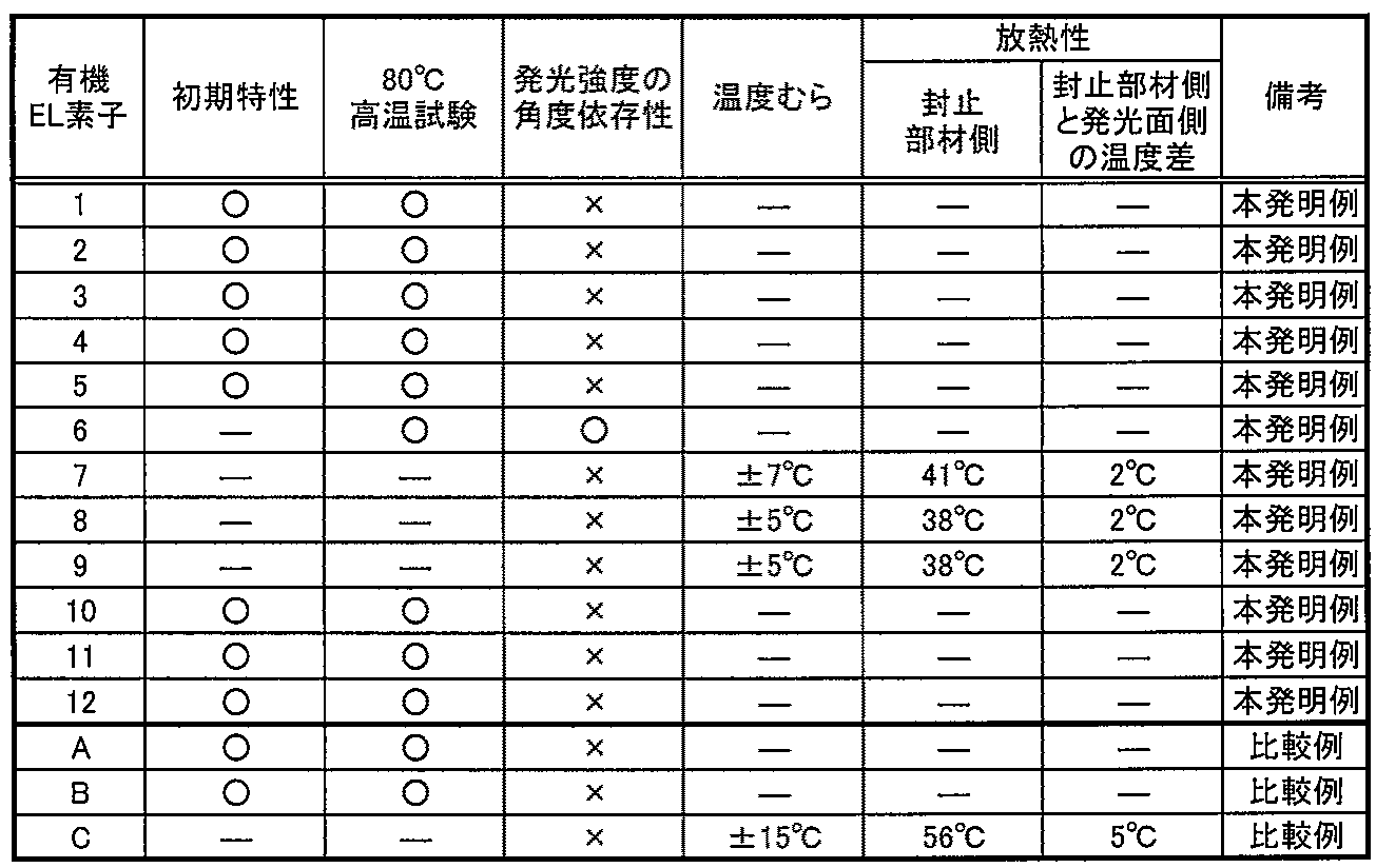
有機EL素子1~5、10~12および有機EL素子A、Bについて、初期特性として、電圧を0Vから15Vまで0.2V刻みに上昇させ、そのときの電流値および輝度値を測定した。いずれの有機EL素子もほぼ同等の良好な特性を示した。
(80℃高温保存試験)
有機EL素子1~6、10~12および有機EL素子A、Bについて、80℃高温保存試験を行い、封止部材からの水分放出の有無を調査した。図13(a)、(b)にそれぞれ有機EL素子Aおよび有機EL素子1の80℃高温保存試験、200時間後の発光状態の写真を示す。また、図14(a)、(b)にそれぞれ有機EL素子Bおよび有機EL素子4の80℃高温保存試験、200時間後の発光状態の写真を示す。吸湿剤を用いてない有機EL素子1~3および有機EL素子Aを比較すると、有機EL素子1~3では、200時間保管後においても、発光エリアのエッジ部からの発光エリアの減少が無いことを確認され、また発光エリア中に発生する黒点の発生は有機EL素子Aと同様の発生となり、封止部材からの水分の放出が極めて少ないことが確認された。
(発光強度の角度依存性)
有機EL素子1~12および有機EL素子A~Cについて、発光面正面を0度として85度までの発光強度の角度依存性を調査した。有機EL素子6では、酸化カルシウム層が発光層にて発した光を拡散させることにより、発光面正面を0度として85度までの発光強度の角度依存性が無いことが確認された。
(温度むらおよび放熱性)
発光エリアを50mm□とした有機EL素子7~9および有機EL素子Cについて、50mm□内の3000cd/m2にて点灯させてから10分後の面内の温度むらおよび放熱性を評価した。温度むらについては、K熱電対を用い、室温26.5℃にて、発光面であるガラス基板側から、発光エリアの任意の9箇所の温度を測定した。放熱特性については、K熱電対を用い、室温26.5℃にて、封止部材側および発光面側の両側から、発光エリアの中心部の温度を測定した。有機EL素子7~9は、有機EL素子Cと比較し、温度むらおよび放熱性が共に優れていた。有機EL素子7~9の結果から、図6に示すようにSUS箔の形状を空気との接触面に凹凸を有する形状とする、すなわちヒートシンクを導入することにより、さらに大きい放熱効果を期待できることを確認した。また、ガラス製の封止部材を有し熱伝導性封止部材がない有機EL素子Cはパネル点灯10分後まで温度上昇したが、熱伝導性封止部材を有する有機EL素子7では8分で定常状態、有機EL素子8では7分で定常状態、有機EL素子9では6分で定常状態となり、放熱の効果が確認された。
よって、本発明例の熱伝導性封止部材は、従来のガラス製の封止部材と比較し、有機EL素子の放熱や均熱に、良好に機能することが確認された。
2 … 金属基材
3 … 絶縁層
4 … 粘着層
5 … 剥離層
6 … 防湿部
10 … 外縁部
20 … EL素子
21 … 透明基板
22 … 透明電極層
23 … EL層
24 … 背面電極層
25 … 封止樹脂部
Claims (22)
- 金属基材と、前記金属基材上に形成され、熱伝導性を有し、少なくともポリイミドを含有する絶縁層と、前記絶縁層上に形成され、耐熱性を有する粘着層とを有することを特徴とする熱伝導性封止部材。
- 前記絶縁層がポリイミドを主成分とすることを特徴とする請求の範囲第1項に記載の熱伝導性封止部材。
- 前記粘着層上に剥離層が形成されていることを特徴とする請求の範囲第1項または第2項に記載の熱伝導性封止部材。
- 前記剥離層がガスバリア性を有することを特徴とする請求の範囲第3項に記載の熱伝導性封止部材。
- 前記絶縁層の厚みが0.5μm~100μmの範囲内であることを特徴とする請求の範囲第1項から第4項までのいずれかに記載の熱伝導性封止部材。
- 前記絶縁層の吸湿膨張係数が0ppm/%RH~15ppm/%RHの範囲内であることを特徴とする請求の範囲第1項から第5項までのいずれかに記載の熱伝導性封止部材。
- 前記絶縁層の線熱膨張係数が0ppm/℃~30ppm/℃の範囲内であることを特徴とする請求の範囲第1項から第6項までのいずれかに記載の熱伝導性封止部材。
- 前記絶縁層の線熱膨張係数と前記金属基材の線熱膨張係数との差が15ppm/℃以下であることを特徴とする請求の範囲第1項から第7項までのいずれかに記載の熱伝導性封止部材。
- 前記粘着層を構成する粘着剤の5%重量減少温度が80℃以上であることを特徴とする請求の範囲第1項から第8項までのいずれかに記載の熱伝導性封止部材。
- 前記粘着層が硬化型粘着剤を含有することを特徴とする請求の範囲第1項から第9項までのいずれかに記載の熱伝導性封止部材。
- 前記粘着層がポリイミド系樹脂を含有することを特徴とする請求の範囲第1項から第10項までのいずれかに記載の熱伝導性封止部材。
- 前記粘着層がアクリル系樹脂を含有することを特徴とする請求の範囲第1項から第10項までのいずれかに記載の熱伝導性封止部材。
- 前記粘着層がポリエステル系樹脂を含有することを特徴とする請求の範囲第1項から第10項までのいずれかに記載の熱伝導性封止部材。
- 前記粘着層がシリコーン系樹脂を含有することを特徴とする請求の範囲第1項から第10項までのいずれかに記載の熱伝導性封止部材。
- 前記粘着層を構成する粘着剤のガラス転移温度(Tg)が100℃以下であることを特徴とする請求の範囲第1項から第14項までのいずれかに記載の熱伝導性封止部材。
- 前記粘着層の室温での貯蔵弾性率が1.0×10²Pa以上1.0×10⁷Pa以下であることを特徴とする請求の範囲第1項から第15項までのいずれかに記載の熱伝導性封止部材。
- 前記粘着層が吸湿剤を含有することを特徴とする請求の範囲第1項から第16項までのいずれかに記載の熱伝導性封止部材。
- 前記金属基材が、空気との接触面に凹凸を有することを特徴とする請求の範囲第1項から第17項までのいずれかに記載の熱伝導性封止部材。
- 透明基板と、前記透明基板上に形成された透明電極層と、前記透明電極層上に形成され、少なくとも発光層を含むエレクトロルミネッセンス層と、前記エレクトロルミネッセンス層上に形成された背面電極層と、前記透明電極層、前記エレクトロルミネッセンス層、および前記背面電極層を覆うように形成された熱伝導性封止部材とを有するエレクトロルミネッセンス素子であって、
前記熱伝導性封止部材が、金属基材と、前記金属基材上に形成され、熱伝導性を有し、少なくともポリイミドを含有する絶縁層と、前記絶縁層上に形成され、耐熱性を有する粘着層とを有し、前記粘着層が記透明電極層、前記エレクトロルミネッセンス層、および前記背面電極層を覆うように前記透明基板に接着されていることを特徴とするエレクトロルミネッセンス素子。 - 前記透明基板上に前記熱伝導性封止部材の外周を囲むように封止樹脂部が形成されていることを特徴とする請求の範囲第19項に記載のエレクトロルミネッセンス素子。
- 前記封止樹脂部が吸湿剤を含有することを特徴とする請求の範囲第20項に記載のエレクトロルミネッセンス素子。
- 前記背面電極層が透明性を有し、前記背面電極層と前記熱伝導性封止部材との間に白色反射層が形成されていることを特徴とする請求の範囲第19項から第21項までのいずれかに記載のエレクトロルミネッセンス素子。
Priority Applications (2)
| Application Number | Priority Date | Filing Date | Title |
|---|---|---|---|
| JP2011534269A JP5673546B2 (ja) | 2009-09-30 | 2010-09-29 | 熱伝導性封止部材およびエレクトロルミネッセンス素子 |
| US13/496,973 US9647242B2 (en) | 2009-09-30 | 2010-09-29 | Heat-conductive sealing member and electroluminescent element |
Applications Claiming Priority (4)
| Application Number | Priority Date | Filing Date | Title |
|---|---|---|---|
| JP2009228711 | 2009-09-30 | ||
| JP2009-228711 | 2009-09-30 | ||
| JP2010-090947 | 2010-04-09 | ||
| JP2010090947 | 2010-04-09 |
Publications (1)
| Publication Number | Publication Date |
|---|---|
| WO2011040441A1 true WO2011040441A1 (ja) | 2011-04-07 |
Family
ID=43826257
Family Applications (1)
| Application Number | Title | Priority Date | Filing Date |
|---|---|---|---|
| PCT/JP2010/066913 Ceased WO2011040441A1 (ja) | 2009-09-30 | 2010-09-29 | 熱伝導性封止部材およびエレクトロルミネッセンス素子 |
Country Status (3)
| Country | Link |
|---|---|
| US (1) | US9647242B2 (ja) |
| JP (1) | JP5673546B2 (ja) |
| WO (1) | WO2011040441A1 (ja) |
Cited By (15)
| Publication number | Priority date | Publication date | Assignee | Title |
|---|---|---|---|---|
| KR20140136902A (ko) * | 2013-05-21 | 2014-12-01 | 주식회사 엘지화학 | 봉지 필름 및 이를 이용한 유기전자장치의 봉지 방법 |
| WO2015194156A1 (ja) * | 2014-06-19 | 2015-12-23 | パナソニックIpマネジメント株式会社 | 発光装置 |
| KR101585731B1 (ko) * | 2013-12-24 | 2016-01-14 | 주식회사 포스코 | 유기전자소자용 봉지재, 상기 봉지재의 제조방법, 상기 봉지재를 이용한 유기전자소자의 봉지방법 및 봉지된 유기전자소자 |
| JP2017052268A (ja) * | 2015-06-17 | 2017-03-16 | 長興材料工業股▲ふん▼有限公司Eternal Materials Co.,Ltd. | 金属張積層板、その製造方法、並びに、それを用いるフレキシブル回路基板の製造方法 |
| JP2017208236A (ja) * | 2016-05-18 | 2017-11-24 | 双葉電子工業株式会社 | 乾燥剤組成物、封止構造、及び有機el素子 |
| JP2017212437A (ja) * | 2016-05-18 | 2017-11-30 | 株式会社半導体エネルギー研究所 | 剥離方法、表示装置、モジュール、及び電子機器 |
| JP2018511157A (ja) * | 2015-01-29 | 2018-04-19 | モメンティブ・パフォーマンス・マテリアルズ・コリア・カンパニー・リミテッドMomentive Performance Materials Korea Co.,Ltd | 有機電子素子封止材用組成物およびこれを用いて形成された封止材 |
| JPWO2018088387A1 (ja) * | 2016-11-10 | 2019-10-03 | リンテック株式会社 | ガスバリア性積層シート、ガスバリア性積層シートの製造方法、及び電子部材又は光学部材 |
| WO2019189930A1 (ja) * | 2018-03-30 | 2019-10-03 | 東洋製罐グループホールディングス株式会社 | 有機エレクトロニクスデバイス用封止材 |
| JP2021084994A (ja) * | 2019-11-29 | 2021-06-03 | Hdマイクロシステムズ株式会社 | 樹脂組成物、硬化物の製造方法、硬化物、カバーコート層、表面保護膜及び電子部品 |
| JP2022021714A (ja) * | 2020-07-22 | 2022-02-03 | 味の素株式会社 | 封止用シートおよびポリマー組成物層 |
| US11637009B2 (en) | 2016-10-07 | 2023-04-25 | Semiconductor Energy Laboratory Co., Ltd. | Cleaning method of glass substrate, manufacturing method of semiconductor device, and glass substrate |
| US11712040B2 (en) | 2012-01-12 | 2023-08-01 | Fbsciences Holdings, Inc. | Modulation of plant biology |
| GB2623616A (en) * | 2022-10-17 | 2024-04-24 | Lg Display Co Ltd | Electroluminescent display device |
| TWI865668B (zh) * | 2019-11-29 | 2024-12-11 | 日商艾曲迪微系統股份有限公司 | 樹脂組成物、硬化物的製造方法、硬化物、覆蓋塗層、表面保護膜和電子零件 |
Families Citing this family (15)
| Publication number | Priority date | Publication date | Assignee | Title |
|---|---|---|---|---|
| KR101474630B1 (ko) * | 2012-01-06 | 2014-12-19 | 주식회사 엘지화학 | 봉지용 필름 |
| JP6105063B2 (ja) * | 2012-08-03 | 2017-03-29 | エルジー・ケム・リミテッド | 接着フィルム及びこれを利用した有機電子装置の封止製品 |
| DE102012109140B4 (de) | 2012-09-27 | 2021-06-24 | Pictiva Displays International Limited | Optoelektronisches Bauelement und Verfahren zum Herstellen eines optoelektronischen Bauelementes |
| DE102014202945B4 (de) * | 2014-02-18 | 2017-01-05 | Fraunhofer-Gesellschaft zur Förderung der angewandten Forschung e.V. | Verfahren zum Herstellen eines organischen elektronischen Bauelementes und organisches elektronisches Bauelement |
| CN106415875B (zh) * | 2014-03-27 | 2018-12-25 | 株式会社Lg化学 | 封装膜及包括该封装膜的有机电子装置 |
| EP3176225B1 (en) * | 2014-07-29 | 2020-02-19 | Boe Technology Group Co. Ltd. | Functional material, preparation method therefor, organic light-emitting diode display panel |
| US9541764B2 (en) * | 2014-07-29 | 2017-01-10 | Boe Technology Group Co., Ltd. | Functional material and method for preparing the same, three-dimensional display raster and display device |
| EP3176227B1 (en) * | 2014-07-29 | 2020-01-01 | Boe Technology Group Co. Ltd. | Sealing material and display panel |
| KR101829971B1 (ko) * | 2015-02-17 | 2018-02-19 | 주식회사 엘지화학 | 봉지 필름 |
| KR101810855B1 (ko) * | 2015-04-21 | 2017-12-20 | 도레이 카부시키가이샤 | 적층 부재 및 터치 패널 |
| JP2017009725A (ja) * | 2015-06-19 | 2017-01-12 | ソニー株式会社 | 表示装置 |
| KR102343734B1 (ko) * | 2017-07-12 | 2021-12-28 | 삼성디스플레이 주식회사 | 표시장치 |
| KR102333188B1 (ko) * | 2018-05-14 | 2021-11-30 | 주식회사 엘지화학 | 방열특성이 우수한 플렉서블 디스플레이 소자 기판용 폴리이미드 필름 |
| CN109346622A (zh) * | 2018-10-19 | 2019-02-15 | 武汉华星光电半导体显示技术有限公司 | Oled阵列基板及其制作方法 |
| JP2021114430A (ja) * | 2020-01-21 | 2021-08-05 | 日本航空電子工業株式会社 | コネクタ |
Citations (9)
| Publication number | Priority date | Publication date | Assignee | Title |
|---|---|---|---|---|
| JP2001203076A (ja) * | 1999-11-09 | 2001-07-27 | Semiconductor Energy Lab Co Ltd | 発光装置及びその作製方法 |
| JP2004079292A (ja) * | 2002-08-13 | 2004-03-11 | Matsushita Electric Works Ltd | 有機電界発光素子用封止部材 |
| JP2005259573A (ja) * | 2004-03-12 | 2005-09-22 | Nippon Seiki Co Ltd | 有機elパネルとその製造方法 |
| JP2006128022A (ja) * | 2004-11-01 | 2006-05-18 | Seiko Epson Corp | 発光装置、発光装置の製造方法、及び電子機器 |
| JP2006147528A (ja) * | 2004-10-22 | 2006-06-08 | Seiko Epson Corp | 有機エレクトロルミネッセンス装置の製造方法、及び有機エレクトロルミネッセンス装置 |
| JP2007099951A (ja) * | 2005-10-05 | 2007-04-19 | Dainippon Printing Co Ltd | 低膨張性ポリイミド、樹脂組成物及び物品 |
| JP2007254743A (ja) * | 2002-06-17 | 2007-10-04 | Sekisui Chem Co Ltd | 有機エレクトロルミネッセンス素子封止用接着剤、有機エレクトロルミネッセンス素子封止用粘着テープ、有機エレクトロルミネッセンス素子封止用両面粘着テープ、有機エレクトロルミネッセンス素子の封止方法、及び、有機エレクトロルミネッセンス素子 |
| JP2008010211A (ja) * | 2006-06-27 | 2008-01-17 | Matsushita Electric Works Ltd | 有機エレクトロルミネッセンス発光装置及び有機エレクトロルミネッセンス照明装置 |
| WO2009054168A1 (ja) * | 2007-10-22 | 2009-04-30 | Sharp Kabushiki Kaisha | 表示装置及びその製造方法 |
Family Cites Families (9)
| Publication number | Priority date | Publication date | Assignee | Title |
|---|---|---|---|---|
| JPH0454198U (ja) | 1990-09-14 | 1992-05-08 | ||
| JP4447269B2 (ja) * | 2003-08-29 | 2010-04-07 | 大日本印刷株式会社 | ガスバリア性フィルムを用いた光学フィルター及び有機elディスプレイ |
| JP2005093358A (ja) | 2003-09-19 | 2005-04-07 | Fuji Photo Film Co Ltd | 交流動作エレクトロルミネッセンス素子およびその製造方法 |
| JP2006255918A (ja) | 2005-03-15 | 2006-09-28 | Toray Ind Inc | 光学用フィルム積層体 |
| JP2006286220A (ja) | 2005-03-31 | 2006-10-19 | Nippon Zeon Co Ltd | 有機エレクトロルミネッセンス素子 |
| JP2006331695A (ja) | 2005-05-23 | 2006-12-07 | Matsushita Electric Works Ltd | 有機発光素子用封止部材及び有機発光素子 |
| JP2006331694A (ja) | 2005-05-23 | 2006-12-07 | Matsushita Electric Works Ltd | 有機発光素子及び有機発光素子用基板 |
| JP5144041B2 (ja) | 2006-07-26 | 2013-02-13 | パナソニック株式会社 | 有機エレクトロルミネッセンス発光装置及び有機エレクトロルミネッセンス照明装置 |
| JP4861206B2 (ja) | 2007-01-26 | 2012-01-25 | パナソニック電工株式会社 | 有機エレクトロルミネッセンス発光装置及び有機エレクトロルミネッセンス照明装置 |
-
2010
- 2010-09-29 JP JP2011534269A patent/JP5673546B2/ja not_active Expired - Fee Related
- 2010-09-29 WO PCT/JP2010/066913 patent/WO2011040441A1/ja not_active Ceased
- 2010-09-29 US US13/496,973 patent/US9647242B2/en active Active
Patent Citations (9)
| Publication number | Priority date | Publication date | Assignee | Title |
|---|---|---|---|---|
| JP2001203076A (ja) * | 1999-11-09 | 2001-07-27 | Semiconductor Energy Lab Co Ltd | 発光装置及びその作製方法 |
| JP2007254743A (ja) * | 2002-06-17 | 2007-10-04 | Sekisui Chem Co Ltd | 有機エレクトロルミネッセンス素子封止用接着剤、有機エレクトロルミネッセンス素子封止用粘着テープ、有機エレクトロルミネッセンス素子封止用両面粘着テープ、有機エレクトロルミネッセンス素子の封止方法、及び、有機エレクトロルミネッセンス素子 |
| JP2004079292A (ja) * | 2002-08-13 | 2004-03-11 | Matsushita Electric Works Ltd | 有機電界発光素子用封止部材 |
| JP2005259573A (ja) * | 2004-03-12 | 2005-09-22 | Nippon Seiki Co Ltd | 有機elパネルとその製造方法 |
| JP2006147528A (ja) * | 2004-10-22 | 2006-06-08 | Seiko Epson Corp | 有機エレクトロルミネッセンス装置の製造方法、及び有機エレクトロルミネッセンス装置 |
| JP2006128022A (ja) * | 2004-11-01 | 2006-05-18 | Seiko Epson Corp | 発光装置、発光装置の製造方法、及び電子機器 |
| JP2007099951A (ja) * | 2005-10-05 | 2007-04-19 | Dainippon Printing Co Ltd | 低膨張性ポリイミド、樹脂組成物及び物品 |
| JP2008010211A (ja) * | 2006-06-27 | 2008-01-17 | Matsushita Electric Works Ltd | 有機エレクトロルミネッセンス発光装置及び有機エレクトロルミネッセンス照明装置 |
| WO2009054168A1 (ja) * | 2007-10-22 | 2009-04-30 | Sharp Kabushiki Kaisha | 表示装置及びその製造方法 |
Cited By (25)
| Publication number | Priority date | Publication date | Assignee | Title |
|---|---|---|---|---|
| US12193442B2 (en) | 2012-01-12 | 2025-01-14 | Fbsciences Holdings, Inc. | Modulation of plant biology |
| US11712040B2 (en) | 2012-01-12 | 2023-08-01 | Fbsciences Holdings, Inc. | Modulation of plant biology |
| KR101589374B1 (ko) | 2013-05-21 | 2016-01-28 | 주식회사 엘지화학 | 봉지 필름 및 이를 이용한 유기전자장치의 봉지 방법 |
| KR20140136902A (ko) * | 2013-05-21 | 2014-12-01 | 주식회사 엘지화학 | 봉지 필름 및 이를 이용한 유기전자장치의 봉지 방법 |
| KR101585731B1 (ko) * | 2013-12-24 | 2016-01-14 | 주식회사 포스코 | 유기전자소자용 봉지재, 상기 봉지재의 제조방법, 상기 봉지재를 이용한 유기전자소자의 봉지방법 및 봉지된 유기전자소자 |
| WO2015194156A1 (ja) * | 2014-06-19 | 2015-12-23 | パナソニックIpマネジメント株式会社 | 発光装置 |
| JP2018511157A (ja) * | 2015-01-29 | 2018-04-19 | モメンティブ・パフォーマンス・マテリアルズ・コリア・カンパニー・リミテッドMomentive Performance Materials Korea Co.,Ltd | 有機電子素子封止材用組成物およびこれを用いて形成された封止材 |
| JP2017052268A (ja) * | 2015-06-17 | 2017-03-16 | 長興材料工業股▲ふん▼有限公司Eternal Materials Co.,Ltd. | 金属張積層板、その製造方法、並びに、それを用いるフレキシブル回路基板の製造方法 |
| US10475820B2 (en) | 2016-05-18 | 2019-11-12 | Semiconductor Energy Laboratory Co., Ltd. | Peeling method, display device, module, and electronic device |
| JP2017208236A (ja) * | 2016-05-18 | 2017-11-24 | 双葉電子工業株式会社 | 乾燥剤組成物、封止構造、及び有機el素子 |
| CN107452899A (zh) * | 2016-05-18 | 2017-12-08 | 株式会社半导体能源研究所 | 剥离方法、显示装置、模块及电子设备 |
| JP2017212437A (ja) * | 2016-05-18 | 2017-11-30 | 株式会社半導体エネルギー研究所 | 剥離方法、表示装置、モジュール、及び電子機器 |
| US12437985B2 (en) | 2016-10-07 | 2025-10-07 | Semiconductor Energy Laboratory Co., Ltd. | Cleaning method of glass substrate, manufacturing method of semiconductor device, and glass substrate |
| US11637009B2 (en) | 2016-10-07 | 2023-04-25 | Semiconductor Energy Laboratory Co., Ltd. | Cleaning method of glass substrate, manufacturing method of semiconductor device, and glass substrate |
| JPWO2018088387A1 (ja) * | 2016-11-10 | 2019-10-03 | リンテック株式会社 | ガスバリア性積層シート、ガスバリア性積層シートの製造方法、及び電子部材又は光学部材 |
| JP7080180B2 (ja) | 2016-11-10 | 2022-06-03 | リンテック株式会社 | ガスバリア性積層シート、ガスバリア性積層シートの製造方法、及び電子部材又は光学部材 |
| WO2019189930A1 (ja) * | 2018-03-30 | 2019-10-03 | 東洋製罐グループホールディングス株式会社 | 有機エレクトロニクスデバイス用封止材 |
| JP2019179705A (ja) * | 2018-03-30 | 2019-10-17 | 東洋製罐グループホールディングス株式会社 | 有機エレクトロニクスデバイス用封止材 |
| JP2021084994A (ja) * | 2019-11-29 | 2021-06-03 | Hdマイクロシステムズ株式会社 | 樹脂組成物、硬化物の製造方法、硬化物、カバーコート層、表面保護膜及び電子部品 |
| TWI865668B (zh) * | 2019-11-29 | 2024-12-11 | 日商艾曲迪微系統股份有限公司 | 樹脂組成物、硬化物的製造方法、硬化物、覆蓋塗層、表面保護膜和電子零件 |
| JP7451970B2 (ja) | 2019-11-29 | 2024-03-19 | Hdマイクロシステムズ株式会社 | 樹脂組成物、硬化物の製造方法、硬化物、カバーコート層、表面保護膜及び電子部品 |
| JP7528605B2 (ja) | 2020-07-22 | 2024-08-06 | 味の素株式会社 | 封止用シートおよびポリマー組成物層 |
| JP2022021714A (ja) * | 2020-07-22 | 2022-02-03 | 味の素株式会社 | 封止用シートおよびポリマー組成物層 |
| GB2623616A (en) * | 2022-10-17 | 2024-04-24 | Lg Display Co Ltd | Electroluminescent display device |
| GB2623616B (en) * | 2022-10-17 | 2025-10-15 | Lg Display Co Ltd | Electroluminescent display device |
Also Published As
| Publication number | Publication date |
|---|---|
| US20120181914A1 (en) | 2012-07-19 |
| US9647242B2 (en) | 2017-05-09 |
| JP5673546B2 (ja) | 2015-02-18 |
| JPWO2011040441A1 (ja) | 2013-02-28 |
Similar Documents
| Publication | Publication Date | Title |
|---|---|---|
| JP5673546B2 (ja) | 熱伝導性封止部材およびエレクトロルミネッセンス素子 | |
| JP2011222334A (ja) | 熱伝導性封止部材および素子 | |
| WO2011126083A1 (ja) | 熱伝導性封止部材およびそれにより封止された電子デバイス | |
| CN102481764B (zh) | 玻璃/树脂层叠体、及使用其的电子设备 | |
| CN114207520B (zh) | 感光性树脂组合物、感光性片、固化膜、固化膜的制造方法、层间绝缘膜及电子部件 | |
| JP6094044B2 (ja) | 放熱基板およびそれを用いた素子 | |
| JP2013077521A (ja) | 電磁波剥離性フレキシブルデバイス用基板およびそれを用いた電子素子の製造方法 | |
| TWI549200B (zh) | 電子元件用積層基板,電子元件,有機電致發光顯示裝置,電子紙及電子元件用積層基板之製造方法 | |
| JP5422878B2 (ja) | 半導体用接着組成物、それを用いた半導体装置および半導体装置の製造方法 | |
| CN107722268A (zh) | 聚酰亚胺前体、聚酰亚胺及透明聚酰亚胺膜的制造方法 | |
| JP6032254B2 (ja) | パワーモジュール用金属配線付基板、パワーモジュール及びパワーモジュール用基板、並びにパワーモジュール用金属配線付基板の製造方法 | |
| CN108138013A (zh) | 临时粘合用层叠体膜、使用临时粘合用层叠体膜的基板加工体及层叠基板加工体的制造方法、以及使用它们的半导体器件的制造方法 | |
| CN103168077A (zh) | 树脂组合物、层叠体及其制造方法、结构体及其制造方法以及电子器件的制造方法 | |
| CN112368641A (zh) | 感光性树脂组合物、感光性片材、以及它们的固化膜及其制造方法、电子部件 | |
| JP3979792B2 (ja) | 静電チャック装置用接着シート及び静電チャック装置 | |
| CN108431135A (zh) | 树脂组合物、树脂的制造方法、树脂膜的制造方法和电子设备的制造方法 | |
| CN109679094B (zh) | 聚酰亚胺前体及聚酰亚胺、层叠体、可挠性器件 | |
| TWI786055B (zh) | 聚醯亞胺前體及由所述聚醯亞胺前體生成的聚醯亞胺 | |
| WO2022210154A1 (ja) | 積層体および半導体装置の製造方法 | |
| JP2023021385A (ja) | 半導体装置の製造方法、及び、樹脂シート | |
| JP2026026198A (ja) | 樹脂シート | |
| TW201840415A (zh) | 阻氣性薄膜及密封體 | |
| JP5292793B2 (ja) | 半導体用接着シート、それを用いた半導体装置および半導体装置の製造方法 | |
| JP2011153325A (ja) | 除塵用基板に好適な耐熱性樹脂 | |
| JP4820615B2 (ja) | 基板処理装置の除塵用基板及びそれを用いた除塵方法 |
Legal Events
| Date | Code | Title | Description |
|---|---|---|---|
| 121 | Ep: the epo has been informed by wipo that ep was designated in this application |
Ref document number: 10820556 Country of ref document: EP Kind code of ref document: A1 |
|
| WWE | Wipo information: entry into national phase |
Ref document number: 2011534269 Country of ref document: JP |
|
| WWE | Wipo information: entry into national phase |
Ref document number: 13496973 Country of ref document: US |
|
| NENP | Non-entry into the national phase |
Ref country code: DE |
|
| 122 | Ep: pct application non-entry in european phase |
Ref document number: 10820556 Country of ref document: EP Kind code of ref document: A1 |