WO2011126083A1 - 熱伝導性封止部材およびそれにより封止された電子デバイス - Google Patents
熱伝導性封止部材およびそれにより封止された電子デバイス Download PDFInfo
- Publication number
- WO2011126083A1 WO2011126083A1 PCT/JP2011/058836 JP2011058836W WO2011126083A1 WO 2011126083 A1 WO2011126083 A1 WO 2011126083A1 JP 2011058836 W JP2011058836 W JP 2011058836W WO 2011126083 A1 WO2011126083 A1 WO 2011126083A1
- Authority
- WO
- WIPO (PCT)
- Prior art keywords
- insulating layer
- sealing member
- polyimide
- conductive sealing
- layer
- Prior art date
Links
- 238000007789 sealing Methods 0.000 title claims abstract description 319
- 229910052751 metal Inorganic materials 0.000 claims abstract description 141
- 239000002184 metal Substances 0.000 claims abstract description 141
- 229920005989 resin Polymers 0.000 claims abstract description 138
- 239000011347 resin Substances 0.000 claims abstract description 138
- 239000000758 substrate Substances 0.000 claims abstract description 135
- 230000004888 barrier function Effects 0.000 claims abstract description 103
- 239000010410 layer Substances 0.000 claims description 510
- 229920001721 polyimide Polymers 0.000 claims description 239
- 239000004642 Polyimide Substances 0.000 claims description 181
- 239000012790 adhesive layer Substances 0.000 claims description 60
- 239000000463 material Substances 0.000 claims description 45
- 230000005606 hygroscopic expansion Effects 0.000 claims description 31
- 230000002093 peripheral effect Effects 0.000 claims description 11
- 238000009751 slip forming Methods 0.000 claims description 11
- 238000009413 insulation Methods 0.000 abstract description 14
- 230000017525 heat dissipation Effects 0.000 abstract description 13
- 239000010408 film Substances 0.000 description 116
- 238000000034 method Methods 0.000 description 105
- GTDPSWPPOUPBNX-UHFFFAOYSA-N ac1mqpva Chemical compound CC12C(=O)OC(=O)C1(C)C1(C)C2(C)C(=O)OC1=O GTDPSWPPOUPBNX-UHFFFAOYSA-N 0.000 description 80
- -1 polyethylene terephthalate Polymers 0.000 description 80
- 150000004985 diamines Chemical class 0.000 description 45
- 239000002585 base Substances 0.000 description 44
- 239000011888 foil Substances 0.000 description 44
- 239000009719 polyimide resin Substances 0.000 description 44
- 239000002243 precursor Substances 0.000 description 44
- UHOVQNZJYSORNB-UHFFFAOYSA-N Benzene Chemical compound C1=CC=CC=C1 UHOVQNZJYSORNB-UHFFFAOYSA-N 0.000 description 42
- 238000004519 manufacturing process Methods 0.000 description 42
- 229910052757 nitrogen Inorganic materials 0.000 description 40
- 239000003822 epoxy resin Substances 0.000 description 36
- 229920000647 polyepoxide Polymers 0.000 description 36
- 125000003118 aryl group Chemical group 0.000 description 35
- 239000000203 mixture Substances 0.000 description 34
- 239000007789 gas Substances 0.000 description 30
- 238000002360 preparation method Methods 0.000 description 30
- 239000003230 hygroscopic agent Substances 0.000 description 29
- 239000002253 acid Substances 0.000 description 28
- 229920001187 thermosetting polymer Polymers 0.000 description 28
- 239000000243 solution Substances 0.000 description 27
- 230000000052 comparative effect Effects 0.000 description 26
- 238000010438 heat treatment Methods 0.000 description 26
- 229920003192 poly(bis maleimide) Polymers 0.000 description 24
- 239000002904 solvent Substances 0.000 description 22
- XLYOFNOQVPJJNP-UHFFFAOYSA-N water Substances O XLYOFNOQVPJJNP-UHFFFAOYSA-N 0.000 description 22
- 239000004820 Pressure-sensitive adhesive Substances 0.000 description 21
- 238000010521 absorption reaction Methods 0.000 description 21
- 238000011156 evaluation Methods 0.000 description 21
- SECXISVLQFMRJM-UHFFFAOYSA-N N-Methylpyrrolidone Chemical compound CN1CCCC1=O SECXISVLQFMRJM-UHFFFAOYSA-N 0.000 description 20
- 150000004984 aromatic diamines Chemical class 0.000 description 19
- 239000012299 nitrogen atmosphere Substances 0.000 description 19
- 150000000000 tetracarboxylic acids Chemical class 0.000 description 19
- 239000000853 adhesive Substances 0.000 description 18
- 230000001070 adhesive effect Effects 0.000 description 18
- 229910052731 fluorine Inorganic materials 0.000 description 18
- 238000006243 chemical reaction Methods 0.000 description 16
- 239000011521 glass Substances 0.000 description 16
- 125000000951 phenoxy group Chemical group [H]C1=C([H])C([H])=C(O*)C([H])=C1[H] 0.000 description 16
- 125000001997 phenyl group Chemical group [H]C1=C([H])C([H])=C(*)C([H])=C1[H] 0.000 description 16
- 238000006116 polymerization reaction Methods 0.000 description 16
- RTZKZFJDLAIYFH-UHFFFAOYSA-N Diethyl ether Chemical compound CCOCC RTZKZFJDLAIYFH-UHFFFAOYSA-N 0.000 description 15
- 230000015572 biosynthetic process Effects 0.000 description 15
- 238000002156 mixing Methods 0.000 description 15
- YCKRFDGAMUMZLT-UHFFFAOYSA-N Fluorine atom Chemical compound [F] YCKRFDGAMUMZLT-UHFFFAOYSA-N 0.000 description 14
- 239000011737 fluorine Substances 0.000 description 14
- 238000001771 vacuum deposition Methods 0.000 description 14
- XQUPVDVFXZDTLT-UHFFFAOYSA-N 1-[4-[[4-(2,5-dioxopyrrol-1-yl)phenyl]methyl]phenyl]pyrrole-2,5-dione Chemical compound O=C1C=CC(=O)N1C(C=C1)=CC=C1CC1=CC=C(N2C(C=CC2=O)=O)C=C1 XQUPVDVFXZDTLT-UHFFFAOYSA-N 0.000 description 13
- VYPSYNLAJGMNEJ-UHFFFAOYSA-N Silicium dioxide Chemical compound O=[Si]=O VYPSYNLAJGMNEJ-UHFFFAOYSA-N 0.000 description 13
- 239000003963 antioxidant agent Substances 0.000 description 13
- 125000000962 organic group Chemical group 0.000 description 13
- 229920005575 poly(amic acid) Polymers 0.000 description 13
- 125000006158 tetracarboxylic acid group Chemical group 0.000 description 13
- FXHOOIRPVKKKFG-UHFFFAOYSA-N N,N-Dimethylacetamide Chemical compound CN(C)C(C)=O FXHOOIRPVKKKFG-UHFFFAOYSA-N 0.000 description 12
- ZMXDDKWLCZADIW-UHFFFAOYSA-N N,N-Dimethylformamide Chemical compound CN(C)C=O ZMXDDKWLCZADIW-UHFFFAOYSA-N 0.000 description 12
- YXFVVABEGXRONW-UHFFFAOYSA-N Toluene Chemical compound CC1=CC=CC=C1 YXFVVABEGXRONW-UHFFFAOYSA-N 0.000 description 12
- 125000003277 amino group Chemical group 0.000 description 12
- 238000003860 storage Methods 0.000 description 12
- WYURNTSHIVDZCO-UHFFFAOYSA-N Tetrahydrofuran Chemical group C1CCOC1 WYURNTSHIVDZCO-UHFFFAOYSA-N 0.000 description 11
- 230000003078 antioxidant effect Effects 0.000 description 11
- 239000011651 chromium Substances 0.000 description 11
- 150000001875 compounds Chemical class 0.000 description 11
- 239000007787 solid Substances 0.000 description 11
- CSCPPACGZOOCGX-UHFFFAOYSA-N Acetone Chemical compound CC(C)=O CSCPPACGZOOCGX-UHFFFAOYSA-N 0.000 description 10
- ZUOUZKKEUPVFJK-UHFFFAOYSA-N diphenyl Chemical compound C1=CC=CC=C1C1=CC=CC=C1 ZUOUZKKEUPVFJK-UHFFFAOYSA-N 0.000 description 10
- VNWKTOKETHGBQD-UHFFFAOYSA-N methane Chemical compound C VNWKTOKETHGBQD-UHFFFAOYSA-N 0.000 description 10
- 230000008569 process Effects 0.000 description 10
- 125000002723 alicyclic group Chemical group 0.000 description 9
- WPYMKLBDIGXBTP-UHFFFAOYSA-N benzoic acid Chemical compound OC(=O)C1=CC=CC=C1 WPYMKLBDIGXBTP-UHFFFAOYSA-N 0.000 description 9
- 230000001588 bifunctional effect Effects 0.000 description 9
- 125000001931 aliphatic group Chemical group 0.000 description 8
- 239000007864 aqueous solution Substances 0.000 description 8
- BRPQOXSCLDDYGP-UHFFFAOYSA-N calcium oxide Chemical compound [O-2].[Ca+2] BRPQOXSCLDDYGP-UHFFFAOYSA-N 0.000 description 8
- ODINCKMPIJJUCX-UHFFFAOYSA-N calcium oxide Inorganic materials [Ca]=O ODINCKMPIJJUCX-UHFFFAOYSA-N 0.000 description 8
- 239000000292 calcium oxide Substances 0.000 description 8
- 239000007795 chemical reaction product Substances 0.000 description 8
- 238000000151 deposition Methods 0.000 description 8
- 238000005530 etching Methods 0.000 description 8
- 125000001153 fluoro group Chemical group F* 0.000 description 8
- 229920000139 polyethylene terephthalate Polymers 0.000 description 8
- 239000005020 polyethylene terephthalate Substances 0.000 description 8
- 125000001424 substituent group Chemical group 0.000 description 8
- 238000002834 transmittance Methods 0.000 description 8
- CBCKQZAAMUWICA-UHFFFAOYSA-N 1,4-phenylenediamine Chemical compound NC1=CC=C(N)C=C1 CBCKQZAAMUWICA-UHFFFAOYSA-N 0.000 description 7
- IAYPIBMASNFSPL-UHFFFAOYSA-N Ethylene oxide Chemical compound C1CO1 IAYPIBMASNFSPL-UHFFFAOYSA-N 0.000 description 7
- PXHVJJICTQNCMI-UHFFFAOYSA-N Nickel Chemical compound [Ni] PXHVJJICTQNCMI-UHFFFAOYSA-N 0.000 description 7
- GOOHAUXETOMSMM-UHFFFAOYSA-N Propylene oxide Chemical compound CC1CO1 GOOHAUXETOMSMM-UHFFFAOYSA-N 0.000 description 7
- 230000008901 benefit Effects 0.000 description 7
- 125000004432 carbon atom Chemical group C* 0.000 description 7
- 239000003431 cross linking reagent Substances 0.000 description 7
- 230000006870 function Effects 0.000 description 7
- 239000007769 metal material Substances 0.000 description 7
- 239000011259 mixed solution Substances 0.000 description 7
- 239000003960 organic solvent Substances 0.000 description 7
- 239000011342 resin composition Substances 0.000 description 7
- IJGRMHOSHXDMSA-UHFFFAOYSA-N Atomic nitrogen Chemical compound N#N IJGRMHOSHXDMSA-UHFFFAOYSA-N 0.000 description 6
- OKKJLVBELUTLKV-UHFFFAOYSA-N Methanol Chemical compound OC OKKJLVBELUTLKV-UHFFFAOYSA-N 0.000 description 6
- 239000004734 Polyphenylene sulfide Substances 0.000 description 6
- 230000005540 biological transmission Effects 0.000 description 6
- 239000004305 biphenyl Substances 0.000 description 6
- WKDNYTOXBCRNPV-UHFFFAOYSA-N bpda Chemical compound C1=C2C(=O)OC(=O)C2=CC(C=2C=C3C(=O)OC(C3=CC=2)=O)=C1 WKDNYTOXBCRNPV-UHFFFAOYSA-N 0.000 description 6
- 229910052802 copper Inorganic materials 0.000 description 6
- 239000010949 copper Substances 0.000 description 6
- 230000008021 deposition Effects 0.000 description 6
- 238000011161 development Methods 0.000 description 6
- 230000018109 developmental process Effects 0.000 description 6
- 230000000694 effects Effects 0.000 description 6
- 238000002347 injection Methods 0.000 description 6
- 239000007924 injection Substances 0.000 description 6
- 239000007788 liquid Substances 0.000 description 6
- 229920000069 polyphenylene sulfide Polymers 0.000 description 6
- 239000000047 product Substances 0.000 description 6
- 238000007650 screen-printing Methods 0.000 description 6
- 238000012360 testing method Methods 0.000 description 6
- 239000010409 thin film Substances 0.000 description 6
- 125000002023 trifluoromethyl group Chemical group FC(F)(F)* 0.000 description 6
- WNXJIVFYUVYPPR-UHFFFAOYSA-N 1,3-dioxolane Chemical compound C1COCO1 WNXJIVFYUVYPPR-UHFFFAOYSA-N 0.000 description 5
- HLBLWEWZXPIGSM-UHFFFAOYSA-N 4-Aminophenyl ether Chemical compound C1=CC(N)=CC=C1OC1=CC=C(N)C=C1 HLBLWEWZXPIGSM-UHFFFAOYSA-N 0.000 description 5
- RYGMFSIKBFXOCR-UHFFFAOYSA-N Copper Chemical compound [Cu] RYGMFSIKBFXOCR-UHFFFAOYSA-N 0.000 description 5
- 239000000654 additive Substances 0.000 description 5
- 229910052782 aluminium Inorganic materials 0.000 description 5
- XAGFODPZIPBFFR-UHFFFAOYSA-N aluminium Chemical compound [Al] XAGFODPZIPBFFR-UHFFFAOYSA-N 0.000 description 5
- 239000012298 atmosphere Substances 0.000 description 5
- 235000010290 biphenyl Nutrition 0.000 description 5
- 238000001816 cooling Methods 0.000 description 5
- 238000007334 copolymerization reaction Methods 0.000 description 5
- 238000001723 curing Methods 0.000 description 5
- 230000007423 decrease Effects 0.000 description 5
- 238000007607 die coating method Methods 0.000 description 5
- 238000007646 gravure printing Methods 0.000 description 5
- 150000003949 imides Chemical group 0.000 description 5
- 229910010272 inorganic material Inorganic materials 0.000 description 5
- 239000011147 inorganic material Substances 0.000 description 5
- 238000005259 measurement Methods 0.000 description 5
- 238000012545 processing Methods 0.000 description 5
- 229920002050 silicone resin Polymers 0.000 description 5
- 239000000126 substance Substances 0.000 description 5
- DZIHTWJGPDVSGE-UHFFFAOYSA-N 4-[(4-aminocyclohexyl)methyl]cyclohexan-1-amine Chemical compound C1CC(N)CCC1CC1CCC(N)CC1 DZIHTWJGPDVSGE-UHFFFAOYSA-N 0.000 description 4
- NVKGJHAQGWCWDI-UHFFFAOYSA-N 4-[4-amino-2-(trifluoromethyl)phenyl]-3-(trifluoromethyl)aniline Chemical group FC(F)(F)C1=CC(N)=CC=C1C1=CC=C(N)C=C1C(F)(F)F NVKGJHAQGWCWDI-UHFFFAOYSA-N 0.000 description 4
- 239000004925 Acrylic resin Substances 0.000 description 4
- 229920000178 Acrylic resin Polymers 0.000 description 4
- IAZDPXIOMUYVGZ-UHFFFAOYSA-N Dimethylsulphoxide Chemical compound CS(C)=O IAZDPXIOMUYVGZ-UHFFFAOYSA-N 0.000 description 4
- XEEYBQQBJWHFJM-UHFFFAOYSA-N Iron Chemical compound [Fe] XEEYBQQBJWHFJM-UHFFFAOYSA-N 0.000 description 4
- CTQNGGLPUBDAKN-UHFFFAOYSA-N O-Xylene Chemical compound CC1=CC=CC=C1C CTQNGGLPUBDAKN-UHFFFAOYSA-N 0.000 description 4
- 239000004696 Poly ether ether ketone Substances 0.000 description 4
- 239000004372 Polyvinyl alcohol Substances 0.000 description 4
- XLOMVQKBTHCTTD-UHFFFAOYSA-N Zinc monoxide Chemical compound [Zn]=O XLOMVQKBTHCTTD-UHFFFAOYSA-N 0.000 description 4
- 239000002250 absorbent Substances 0.000 description 4
- 230000002745 absorbent Effects 0.000 description 4
- 150000004982 aromatic amines Chemical class 0.000 description 4
- QVQLCTNNEUAWMS-UHFFFAOYSA-N barium oxide Chemical compound [Ba]=O QVQLCTNNEUAWMS-UHFFFAOYSA-N 0.000 description 4
- 238000009835 boiling Methods 0.000 description 4
- 229910052799 carbon Inorganic materials 0.000 description 4
- 238000000576 coating method Methods 0.000 description 4
- 230000006866 deterioration Effects 0.000 description 4
- JAONJTDQXUSBGG-UHFFFAOYSA-N dialuminum;dizinc;oxygen(2-) Chemical compound [O-2].[O-2].[O-2].[O-2].[O-2].[Al+3].[Al+3].[Zn+2].[Zn+2] JAONJTDQXUSBGG-UHFFFAOYSA-N 0.000 description 4
- 230000009477 glass transition Effects 0.000 description 4
- GNOIPBMMFNIUFM-UHFFFAOYSA-N hexamethylphosphoric triamide Chemical compound CN(C)P(=O)(N(C)C)N(C)C GNOIPBMMFNIUFM-UHFFFAOYSA-N 0.000 description 4
- 230000005525 hole transport Effects 0.000 description 4
- 229910052759 nickel Inorganic materials 0.000 description 4
- 239000011368 organic material Substances 0.000 description 4
- 125000004430 oxygen atom Chemical group O* 0.000 description 4
- 230000035515 penetration Effects 0.000 description 4
- 229920002120 photoresistant polymer Polymers 0.000 description 4
- 230000000704 physical effect Effects 0.000 description 4
- 229920002530 polyetherether ketone Polymers 0.000 description 4
- 229920001955 polyphenylene ether Polymers 0.000 description 4
- 229920002451 polyvinyl alcohol Polymers 0.000 description 4
- 238000007639 printing Methods 0.000 description 4
- KIDHWZJUCRJVML-UHFFFAOYSA-N putrescine Chemical compound NCCCCN KIDHWZJUCRJVML-UHFFFAOYSA-N 0.000 description 4
- 229910052703 rhodium Inorganic materials 0.000 description 4
- YLQBMQCUIZJEEH-UHFFFAOYSA-N tetrahydrofuran Natural products C=1C=COC=1 YLQBMQCUIZJEEH-UHFFFAOYSA-N 0.000 description 4
- 125000000876 trifluoromethoxy group Chemical group FC(F)(F)O* 0.000 description 4
- 239000008096 xylene Substances 0.000 description 4
- VLDPXPPHXDGHEW-UHFFFAOYSA-N 1-chloro-2-dichlorophosphoryloxybenzene Chemical compound ClC1=CC=CC=C1OP(Cl)(Cl)=O VLDPXPPHXDGHEW-UHFFFAOYSA-N 0.000 description 3
- ZWEHNKRNPOVVGH-UHFFFAOYSA-N 2-Butanone Chemical compound CCC(C)=O ZWEHNKRNPOVVGH-UHFFFAOYSA-N 0.000 description 3
- UCFMKTNJZCYBBJ-UHFFFAOYSA-N 3-[1-(2,3-dicarboxyphenyl)ethyl]phthalic acid Chemical compound C=1C=CC(C(O)=O)=C(C(O)=O)C=1C(C)C1=CC=CC(C(O)=O)=C1C(O)=O UCFMKTNJZCYBBJ-UHFFFAOYSA-N 0.000 description 3
- DFSUKONUQMHUKQ-UHFFFAOYSA-N 3-[2-(2,3-dicarboxyphenyl)-1,1,1,3,3,3-hexafluoropropan-2-yl]phthalic acid Chemical compound OC(=O)C1=CC=CC(C(C=2C(=C(C(O)=O)C=CC=2)C(O)=O)(C(F)(F)F)C(F)(F)F)=C1C(O)=O DFSUKONUQMHUKQ-UHFFFAOYSA-N 0.000 description 3
- PAHZZOIHRHCHTH-UHFFFAOYSA-N 3-[2-(2,3-dicarboxyphenyl)propan-2-yl]phthalic acid Chemical compound C=1C=CC(C(O)=O)=C(C(O)=O)C=1C(C)(C)C1=CC=CC(C(O)=O)=C1C(O)=O PAHZZOIHRHCHTH-UHFFFAOYSA-N 0.000 description 3
- LJMPOXUWPWEILS-UHFFFAOYSA-N 3a,4,4a,7a,8,8a-hexahydrofuro[3,4-f][2]benzofuran-1,3,5,7-tetrone Chemical compound C1C2C(=O)OC(=O)C2CC2C(=O)OC(=O)C21 LJMPOXUWPWEILS-UHFFFAOYSA-N 0.000 description 3
- AVCOFPOLGHKJQB-UHFFFAOYSA-N 4-(3,4-dicarboxyphenyl)sulfonylphthalic acid Chemical compound C1=C(C(O)=O)C(C(=O)O)=CC=C1S(=O)(=O)C1=CC=C(C(O)=O)C(C(O)=O)=C1 AVCOFPOLGHKJQB-UHFFFAOYSA-N 0.000 description 3
- IWXCYYWDGDDPAC-UHFFFAOYSA-N 4-[(3,4-dicarboxyphenyl)methyl]phthalic acid Chemical compound C1=C(C(O)=O)C(C(=O)O)=CC=C1CC1=CC=C(C(O)=O)C(C(O)=O)=C1 IWXCYYWDGDDPAC-UHFFFAOYSA-N 0.000 description 3
- GEYAGBVEAJGCFB-UHFFFAOYSA-N 4-[2-(3,4-dicarboxyphenyl)propan-2-yl]phthalic acid Chemical compound C=1C=C(C(O)=O)C(C(O)=O)=CC=1C(C)(C)C1=CC=C(C(O)=O)C(C(O)=O)=C1 GEYAGBVEAJGCFB-UHFFFAOYSA-N 0.000 description 3
- JCRRFJIVUPSNTA-UHFFFAOYSA-N 4-[4-(4-aminophenoxy)phenoxy]aniline Chemical compound C1=CC(N)=CC=C1OC(C=C1)=CC=C1OC1=CC=C(N)C=C1 JCRRFJIVUPSNTA-UHFFFAOYSA-N 0.000 description 3
- QHHKLPCQTTWFSS-UHFFFAOYSA-N 5-[2-(1,3-dioxo-2-benzofuran-5-yl)-1,1,1,3,3,3-hexafluoropropan-2-yl]-2-benzofuran-1,3-dione Chemical compound C1=C2C(=O)OC(=O)C2=CC(C(C=2C=C3C(=O)OC(=O)C3=CC=2)(C(F)(F)F)C(F)(F)F)=C1 QHHKLPCQTTWFSS-UHFFFAOYSA-N 0.000 description 3
- WFDIJRYMOXRFFG-UHFFFAOYSA-N Acetic anhydride Chemical compound CC(=O)OC(C)=O WFDIJRYMOXRFFG-UHFFFAOYSA-N 0.000 description 3
- WEVYAHXRMPXWCK-UHFFFAOYSA-N Acetonitrile Chemical compound CC#N WEVYAHXRMPXWCK-UHFFFAOYSA-N 0.000 description 3
- 239000004593 Epoxy Substances 0.000 description 3
- LFQSCWFLJHTTHZ-UHFFFAOYSA-N Ethanol Chemical compound CCO LFQSCWFLJHTTHZ-UHFFFAOYSA-N 0.000 description 3
- 229920000219 Ethylene vinyl alcohol Polymers 0.000 description 3
- 229910000990 Ni alloy Inorganic materials 0.000 description 3
- 239000004743 Polypropylene Substances 0.000 description 3
- 239000004793 Polystyrene Substances 0.000 description 3
- BQCADISMDOOEFD-UHFFFAOYSA-N Silver Chemical compound [Ag] BQCADISMDOOEFD-UHFFFAOYSA-N 0.000 description 3
- UCKMPCXJQFINFW-UHFFFAOYSA-N Sulphide Chemical compound [S-2] UCKMPCXJQFINFW-UHFFFAOYSA-N 0.000 description 3
- ATJFFYVFTNAWJD-UHFFFAOYSA-N Tin Chemical compound [Sn] ATJFFYVFTNAWJD-UHFFFAOYSA-N 0.000 description 3
- RTAQQCXQSZGOHL-UHFFFAOYSA-N Titanium Chemical compound [Ti] RTAQQCXQSZGOHL-UHFFFAOYSA-N 0.000 description 3
- 229920001646 UPILEX Polymers 0.000 description 3
- 230000000996 additive effect Effects 0.000 description 3
- 230000002411 adverse Effects 0.000 description 3
- 239000003513 alkali Substances 0.000 description 3
- 239000003795 chemical substances by application Substances 0.000 description 3
- 239000004020 conductor Substances 0.000 description 3
- GEQHKFFSPGPGLN-UHFFFAOYSA-N cyclohexane-1,3-diamine Chemical compound NC1CCCC(N)C1 GEQHKFFSPGPGLN-UHFFFAOYSA-N 0.000 description 3
- 230000018044 dehydration Effects 0.000 description 3
- 238000006297 dehydration reaction Methods 0.000 description 3
- 238000009792 diffusion process Methods 0.000 description 3
- KZTYYGOKRVBIMI-UHFFFAOYSA-N diphenyl sulfone Chemical compound C=1C=CC=CC=1S(=O)(=O)C1=CC=CC=C1 KZTYYGOKRVBIMI-UHFFFAOYSA-N 0.000 description 3
- 238000004049 embossing Methods 0.000 description 3
- 125000001495 ethyl group Chemical group [H]C([H])([H])C([H])([H])* 0.000 description 3
- 239000010419 fine particle Substances 0.000 description 3
- 230000020169 heat generation Effects 0.000 description 3
- 238000005338 heat storage Methods 0.000 description 3
- NAQMVNRVTILPCV-UHFFFAOYSA-N hexane-1,6-diamine Chemical compound NCCCCCCN NAQMVNRVTILPCV-UHFFFAOYSA-N 0.000 description 3
- 125000004435 hydrogen atom Chemical group [H]* 0.000 description 3
- 238000003384 imaging method Methods 0.000 description 3
- 229910003437 indium oxide Inorganic materials 0.000 description 3
- PJXISJQVUVHSOJ-UHFFFAOYSA-N indium(iii) oxide Chemical compound [O-2].[O-2].[O-2].[In+3].[In+3] PJXISJQVUVHSOJ-UHFFFAOYSA-N 0.000 description 3
- 238000002329 infrared spectrum Methods 0.000 description 3
- 238000010030 laminating Methods 0.000 description 3
- FPYJFEHAWHCUMM-UHFFFAOYSA-N maleic anhydride Chemical compound O=C1OC(=O)C=C1 FPYJFEHAWHCUMM-UHFFFAOYSA-N 0.000 description 3
- QSHDDOUJBYECFT-UHFFFAOYSA-N mercury Chemical compound [Hg] QSHDDOUJBYECFT-UHFFFAOYSA-N 0.000 description 3
- 229910052753 mercury Inorganic materials 0.000 description 3
- 150000002739 metals Chemical class 0.000 description 3
- 125000002496 methyl group Chemical group [H]C([H])([H])* 0.000 description 3
- 229910052750 molybdenum Inorganic materials 0.000 description 3
- 150000004767 nitrides Chemical class 0.000 description 3
- 238000010943 off-gassing Methods 0.000 description 3
- 239000012044 organic layer Substances 0.000 description 3
- 238000000059 patterning Methods 0.000 description 3
- 238000000206 photolithography Methods 0.000 description 3
- 229920001155 polypropylene Polymers 0.000 description 3
- 229920002223 polystyrene Polymers 0.000 description 3
- 239000001294 propane Substances 0.000 description 3
- 229910052709 silver Inorganic materials 0.000 description 3
- 239000004332 silver Substances 0.000 description 3
- 238000003786 synthesis reaction Methods 0.000 description 3
- 229910052718 tin Inorganic materials 0.000 description 3
- XOLBLPGZBRYERU-UHFFFAOYSA-N tin dioxide Chemical compound O=[Sn]=O XOLBLPGZBRYERU-UHFFFAOYSA-N 0.000 description 3
- 229910001887 tin oxide Inorganic materials 0.000 description 3
- 239000010936 titanium Substances 0.000 description 3
- 229910052719 titanium Inorganic materials 0.000 description 3
- WZCQRUWWHSTZEM-UHFFFAOYSA-N 1,3-phenylenediamine Chemical compound NC1=CC=CC(N)=C1 WZCQRUWWHSTZEM-UHFFFAOYSA-N 0.000 description 2
- MXPYJVUYLVNEBB-UHFFFAOYSA-N 2-[2-(2-carboxybenzoyl)oxycarbonylbenzoyl]oxycarbonylbenzoic acid Chemical compound OC(=O)C1=CC=CC=C1C(=O)OC(=O)C1=CC=CC=C1C(=O)OC(=O)C1=CC=CC=C1C(O)=O MXPYJVUYLVNEBB-UHFFFAOYSA-N 0.000 description 2
- SMDGQEQWSSYZKX-UHFFFAOYSA-N 3-(2,3-dicarboxyphenoxy)phthalic acid Chemical compound OC(=O)C1=CC=CC(OC=2C(=C(C(O)=O)C=CC=2)C(O)=O)=C1C(O)=O SMDGQEQWSSYZKX-UHFFFAOYSA-N 0.000 description 2
- GWHLJVMSZRKEAQ-UHFFFAOYSA-N 3-(2,3-dicarboxyphenyl)phthalic acid Chemical compound OC(=O)C1=CC=CC(C=2C(=C(C(O)=O)C=CC=2)C(O)=O)=C1C(O)=O GWHLJVMSZRKEAQ-UHFFFAOYSA-N 0.000 description 2
- LJGHYPLBDBRCRZ-UHFFFAOYSA-N 3-(3-aminophenyl)sulfonylaniline Chemical compound NC1=CC=CC(S(=O)(=O)C=2C=C(N)C=CC=2)=C1 LJGHYPLBDBRCRZ-UHFFFAOYSA-N 0.000 description 2
- ZBMISJGHVWNWTE-UHFFFAOYSA-N 3-(4-aminophenoxy)aniline Chemical compound C1=CC(N)=CC=C1OC1=CC=CC(N)=C1 ZBMISJGHVWNWTE-UHFFFAOYSA-N 0.000 description 2
- RNLHGQLZWXBQNY-UHFFFAOYSA-N 3-(aminomethyl)-3,5,5-trimethylcyclohexan-1-amine Chemical compound CC1(C)CC(N)CC(C)(CN)C1 RNLHGQLZWXBQNY-UHFFFAOYSA-N 0.000 description 2
- RHRNYXVSZLSRRP-UHFFFAOYSA-N 3-(carboxymethyl)cyclopentane-1,2,4-tricarboxylic acid Chemical compound OC(=O)CC1C(C(O)=O)CC(C(O)=O)C1C(O)=O RHRNYXVSZLSRRP-UHFFFAOYSA-N 0.000 description 2
- TYKLCAKICHXQNE-UHFFFAOYSA-N 3-[(2,3-dicarboxyphenyl)methyl]phthalic acid Chemical compound OC(=O)C1=CC=CC(CC=2C(=C(C(O)=O)C=CC=2)C(O)=O)=C1C(O)=O TYKLCAKICHXQNE-UHFFFAOYSA-N 0.000 description 2
- UVUCUHVQYAPMEU-UHFFFAOYSA-N 3-[2-(3-aminophenyl)-1,1,1,3,3,3-hexafluoropropan-2-yl]aniline Chemical compound NC1=CC=CC(C(C=2C=C(N)C=CC=2)(C(F)(F)F)C(F)(F)F)=C1 UVUCUHVQYAPMEU-UHFFFAOYSA-N 0.000 description 2
- DOAYUKLNEKRLCQ-UHFFFAOYSA-N 3-[2-(4-aminophenyl)-1,1,1,3,3,3-hexafluoropropan-2-yl]aniline Chemical compound C1=CC(N)=CC=C1C(C(F)(F)F)(C(F)(F)F)C1=CC=CC(N)=C1 DOAYUKLNEKRLCQ-UHFFFAOYSA-N 0.000 description 2
- DKKYOQYISDAQER-UHFFFAOYSA-N 3-[3-(3-aminophenoxy)phenoxy]aniline Chemical compound NC1=CC=CC(OC=2C=C(OC=3C=C(N)C=CC=3)C=CC=2)=C1 DKKYOQYISDAQER-UHFFFAOYSA-N 0.000 description 2
- GPXCORHXFPYJEH-UHFFFAOYSA-N 3-[[3-aminopropyl(dimethyl)silyl]oxy-dimethylsilyl]propan-1-amine Chemical compound NCCC[Si](C)(C)O[Si](C)(C)CCCN GPXCORHXFPYJEH-UHFFFAOYSA-N 0.000 description 2
- YBRVSVVVWCFQMG-UHFFFAOYSA-N 4,4'-diaminodiphenylmethane Chemical compound C1=CC(N)=CC=C1CC1=CC=C(N)C=C1 YBRVSVVVWCFQMG-UHFFFAOYSA-N 0.000 description 2
- FYYYKXFEKMGYLZ-UHFFFAOYSA-N 4-(1,3-dioxo-2-benzofuran-5-yl)-2-benzofuran-1,3-dione Chemical compound C=1C=C2C(=O)OC(=O)C2=CC=1C1=CC=CC2=C1C(=O)OC2=O FYYYKXFEKMGYLZ-UHFFFAOYSA-N 0.000 description 2
- QYIMZXITLDTULQ-UHFFFAOYSA-N 4-(4-amino-2-methylphenyl)-3-methylaniline Chemical group CC1=CC(N)=CC=C1C1=CC=C(N)C=C1C QYIMZXITLDTULQ-UHFFFAOYSA-N 0.000 description 2
- BEKFRNOZJSYWKZ-UHFFFAOYSA-N 4-[2-(4-aminophenyl)-1,1,1,3,3,3-hexafluoropropan-2-yl]aniline Chemical compound C1=CC(N)=CC=C1C(C(F)(F)F)(C(F)(F)F)C1=CC=C(N)C=C1 BEKFRNOZJSYWKZ-UHFFFAOYSA-N 0.000 description 2
- WUPRYUDHUFLKFL-UHFFFAOYSA-N 4-[3-(4-aminophenoxy)phenoxy]aniline Chemical compound C1=CC(N)=CC=C1OC1=CC=CC(OC=2C=CC(N)=CC=2)=C1 WUPRYUDHUFLKFL-UHFFFAOYSA-N 0.000 description 2
- HHLMWQDRYZAENA-UHFFFAOYSA-N 4-[4-[2-[4-(4-aminophenoxy)phenyl]-1,1,1,3,3,3-hexafluoropropan-2-yl]phenoxy]aniline Chemical compound C1=CC(N)=CC=C1OC1=CC=C(C(C=2C=CC(OC=3C=CC(N)=CC=3)=CC=2)(C(F)(F)F)C(F)(F)F)C=C1 HHLMWQDRYZAENA-UHFFFAOYSA-N 0.000 description 2
- HYDATEKARGDBKU-UHFFFAOYSA-N 4-[4-[4-(4-aminophenoxy)phenyl]phenoxy]aniline Chemical group C1=CC(N)=CC=C1OC1=CC=C(C=2C=CC(OC=3C=CC(N)=CC=3)=CC=2)C=C1 HYDATEKARGDBKU-UHFFFAOYSA-N 0.000 description 2
- YGYCECQIOXZODZ-UHFFFAOYSA-N 4415-87-6 Chemical compound O=C1OC(=O)C2C1C1C(=O)OC(=O)C12 YGYCECQIOXZODZ-UHFFFAOYSA-N 0.000 description 2
- VQVIHDPBMFABCQ-UHFFFAOYSA-N 5-(1,3-dioxo-2-benzofuran-5-carbonyl)-2-benzofuran-1,3-dione Chemical compound C1=C2C(=O)OC(=O)C2=CC(C(C=2C=C3C(=O)OC(=O)C3=CC=2)=O)=C1 VQVIHDPBMFABCQ-UHFFFAOYSA-N 0.000 description 2
- QQGYZOYWNCKGEK-UHFFFAOYSA-N 5-[(1,3-dioxo-2-benzofuran-5-yl)oxy]-2-benzofuran-1,3-dione Chemical compound C1=C2C(=O)OC(=O)C2=CC(OC=2C=C3C(=O)OC(C3=CC=2)=O)=C1 QQGYZOYWNCKGEK-UHFFFAOYSA-N 0.000 description 2
- 229910001316 Ag alloy Inorganic materials 0.000 description 2
- 229910001020 Au alloy Inorganic materials 0.000 description 2
- 229910000906 Bronze Inorganic materials 0.000 description 2
- OKTJSMMVPCPJKN-UHFFFAOYSA-N Carbon Chemical compound [C] OKTJSMMVPCPJKN-UHFFFAOYSA-N 0.000 description 2
- 229910000881 Cu alloy Inorganic materials 0.000 description 2
- XDTMQSROBMDMFD-UHFFFAOYSA-N Cyclohexane Chemical compound C1CCCCC1 XDTMQSROBMDMFD-UHFFFAOYSA-N 0.000 description 2
- ZPAKUZKMGJJMAA-UHFFFAOYSA-N Cyclohexane-1,2,4,5-tetracarboxylic acid Chemical compound OC(=O)C1CC(C(O)=O)C(C(O)=O)CC1C(O)=O ZPAKUZKMGJJMAA-UHFFFAOYSA-N 0.000 description 2
- MQJKPEGWNLWLTK-UHFFFAOYSA-N Dapsone Chemical compound C1=CC(N)=CC=C1S(=O)(=O)C1=CC=C(N)C=C1 MQJKPEGWNLWLTK-UHFFFAOYSA-N 0.000 description 2
- PIICEJLVQHRZGT-UHFFFAOYSA-N Ethylenediamine Chemical compound NCCN PIICEJLVQHRZGT-UHFFFAOYSA-N 0.000 description 2
- 229910000640 Fe alloy Inorganic materials 0.000 description 2
- 229910021578 Iron(III) chloride Inorganic materials 0.000 description 2
- ZOKXTWBITQBERF-UHFFFAOYSA-N Molybdenum Chemical compound [Mo] ZOKXTWBITQBERF-UHFFFAOYSA-N 0.000 description 2
- ISWSIDIOOBJBQZ-UHFFFAOYSA-N Phenol Chemical compound OC1=CC=CC=C1 ISWSIDIOOBJBQZ-UHFFFAOYSA-N 0.000 description 2
- OAICVXFJPJFONN-UHFFFAOYSA-N Phosphorus Chemical compound [P] OAICVXFJPJFONN-UHFFFAOYSA-N 0.000 description 2
- NQRYJNQNLNOLGT-UHFFFAOYSA-N Piperidine Chemical compound C1CCNCC1 NQRYJNQNLNOLGT-UHFFFAOYSA-N 0.000 description 2
- 239000004697 Polyetherimide Substances 0.000 description 2
- 239000004698 Polyethylene Substances 0.000 description 2
- 229910001128 Sn alloy Inorganic materials 0.000 description 2
- HCHKCACWOHOZIP-UHFFFAOYSA-N Zinc Chemical compound [Zn] HCHKCACWOHOZIP-UHFFFAOYSA-N 0.000 description 2
- BGYHLZZASRKEJE-UHFFFAOYSA-N [3-[3-(3,5-ditert-butyl-4-hydroxyphenyl)propanoyloxy]-2,2-bis[3-(3,5-ditert-butyl-4-hydroxyphenyl)propanoyloxymethyl]propyl] 3-(3,5-ditert-butyl-4-hydroxyphenyl)propanoate Chemical compound CC(C)(C)C1=C(O)C(C(C)(C)C)=CC(CCC(=O)OCC(COC(=O)CCC=2C=C(C(O)=C(C=2)C(C)(C)C)C(C)(C)C)(COC(=O)CCC=2C=C(C(O)=C(C=2)C(C)(C)C)C(C)(C)C)COC(=O)CCC=2C=C(C(O)=C(C=2)C(C)(C)C)C(C)(C)C)=C1 BGYHLZZASRKEJE-UHFFFAOYSA-N 0.000 description 2
- 239000006096 absorbing agent Substances 0.000 description 2
- 125000004018 acid anhydride group Chemical group 0.000 description 2
- 150000008065 acid anhydrides Chemical group 0.000 description 2
- 229920000122 acrylonitrile butadiene styrene Polymers 0.000 description 2
- 150000001298 alcohols Chemical class 0.000 description 2
- 229910052783 alkali metal Inorganic materials 0.000 description 2
- 150000001340 alkali metals Chemical class 0.000 description 2
- 229910000287 alkaline earth metal oxide Inorganic materials 0.000 description 2
- 229910045601 alloy Inorganic materials 0.000 description 2
- 239000000956 alloy Substances 0.000 description 2
- 150000001408 amides Chemical class 0.000 description 2
- 238000007611 bar coating method Methods 0.000 description 2
- GCAIEATUVJFSMC-UHFFFAOYSA-N benzene-1,2,3,4-tetracarboxylic acid Chemical compound OC(=O)C1=CC=C(C(O)=O)C(C(O)=O)=C1C(O)=O GCAIEATUVJFSMC-UHFFFAOYSA-N 0.000 description 2
- QRUDEWIWKLJBPS-UHFFFAOYSA-N benzotriazole Chemical compound C1=CC=C2N[N][N]C2=C1 QRUDEWIWKLJBPS-UHFFFAOYSA-N 0.000 description 2
- 239000010974 bronze Substances 0.000 description 2
- 150000001721 carbon Chemical group 0.000 description 2
- 230000008859 change Effects 0.000 description 2
- 229910052804 chromium Inorganic materials 0.000 description 2
- 239000011248 coating agent Substances 0.000 description 2
- 239000002131 composite material Substances 0.000 description 2
- 229920001577 copolymer Polymers 0.000 description 2
- KUNSUQLRTQLHQQ-UHFFFAOYSA-N copper tin Chemical compound [Cu].[Sn] KUNSUQLRTQLHQQ-UHFFFAOYSA-N 0.000 description 2
- 238000004132 cross linking Methods 0.000 description 2
- WOSVXXBNNCUXMT-UHFFFAOYSA-N cyclopentane-1,2,3,4-tetracarboxylic acid Chemical compound OC(=O)C1CC(C(O)=O)C(C(O)=O)C1C(O)=O WOSVXXBNNCUXMT-UHFFFAOYSA-N 0.000 description 2
- 230000006378 damage Effects 0.000 description 2
- 238000000354 decomposition reaction Methods 0.000 description 2
- 125000006159 dianhydride group Chemical group 0.000 description 2
- ATUOYWHBWRKTHZ-UHFFFAOYSA-N dimethylmethane Natural products CCC ATUOYWHBWRKTHZ-UHFFFAOYSA-N 0.000 description 2
- 238000003618 dip coating Methods 0.000 description 2
- USIUVYZYUHIAEV-UHFFFAOYSA-N diphenyl ether Chemical compound C=1C=CC=CC=1OC1=CC=CC=C1 USIUVYZYUHIAEV-UHFFFAOYSA-N 0.000 description 2
- 238000004821 distillation Methods 0.000 description 2
- 238000001035 drying Methods 0.000 description 2
- 238000005401 electroluminescence Methods 0.000 description 2
- 150000002148 esters Chemical class 0.000 description 2
- 125000001033 ether group Chemical group 0.000 description 2
- 239000004715 ethylene vinyl alcohol Substances 0.000 description 2
- GBASTSRAHRGUAB-UHFFFAOYSA-N ethylenetetracarboxylic dianhydride Chemical compound O=C1OC(=O)C2=C1C(=O)OC2=O GBASTSRAHRGUAB-UHFFFAOYSA-N 0.000 description 2
- 238000005227 gel permeation chromatography Methods 0.000 description 2
- PCHJSUWPFVWCPO-UHFFFAOYSA-N gold Chemical compound [Au] PCHJSUWPFVWCPO-UHFFFAOYSA-N 0.000 description 2
- 229910052737 gold Inorganic materials 0.000 description 2
- 239000010931 gold Substances 0.000 description 2
- 239000003353 gold alloy Substances 0.000 description 2
- 230000001771 impaired effect Effects 0.000 description 2
- AMGQUBHHOARCQH-UHFFFAOYSA-N indium;oxotin Chemical compound [In].[Sn]=O AMGQUBHHOARCQH-UHFFFAOYSA-N 0.000 description 2
- 229910052809 inorganic oxide Inorganic materials 0.000 description 2
- 229910052742 iron Inorganic materials 0.000 description 2
- RBTARNINKXHZNM-UHFFFAOYSA-K iron trichloride Chemical compound Cl[Fe](Cl)Cl RBTARNINKXHZNM-UHFFFAOYSA-K 0.000 description 2
- 229940018564 m-phenylenediamine Drugs 0.000 description 2
- 239000000395 magnesium oxide Substances 0.000 description 2
- CPLXHLVBOLITMK-UHFFFAOYSA-N magnesium oxide Inorganic materials [Mg]=O CPLXHLVBOLITMK-UHFFFAOYSA-N 0.000 description 2
- AXZKOIWUVFPNLO-UHFFFAOYSA-N magnesium;oxygen(2-) Chemical compound [O-2].[Mg+2] AXZKOIWUVFPNLO-UHFFFAOYSA-N 0.000 description 2
- 230000007257 malfunction Effects 0.000 description 2
- 125000000956 methoxy group Chemical group [H]C([H])([H])O* 0.000 description 2
- 239000011733 molybdenum Substances 0.000 description 2
- 239000000178 monomer Substances 0.000 description 2
- IBHBKWKFFTZAHE-UHFFFAOYSA-N n-[4-[4-(n-naphthalen-1-ylanilino)phenyl]phenyl]-n-phenylnaphthalen-1-amine Chemical compound C1=CC=CC=C1N(C=1C2=CC=CC=C2C=CC=1)C1=CC=C(C=2C=CC(=CC=2)N(C=2C=CC=CC=2)C=2C3=CC=CC=C3C=CC=2)C=C1 IBHBKWKFFTZAHE-UHFFFAOYSA-N 0.000 description 2
- KQSABULTKYLFEV-UHFFFAOYSA-N naphthalene-1,5-diamine Chemical compound C1=CC=C2C(N)=CC=CC2=C1N KQSABULTKYLFEV-UHFFFAOYSA-N 0.000 description 2
- GOGZBMRXLADNEV-UHFFFAOYSA-N naphthalene-2,6-diamine Chemical compound C1=C(N)C=CC2=CC(N)=CC=C21 GOGZBMRXLADNEV-UHFFFAOYSA-N 0.000 description 2
- YTVNOVQHSGMMOV-UHFFFAOYSA-N naphthalenetetracarboxylic dianhydride Chemical compound C1=CC(C(=O)OC2=O)=C3C2=CC=C2C(=O)OC(=O)C1=C32 YTVNOVQHSGMMOV-UHFFFAOYSA-N 0.000 description 2
- 239000002530 phenolic antioxidant Substances 0.000 description 2
- 230000002165 photosensitisation Effects 0.000 description 2
- 239000003504 photosensitizing agent Substances 0.000 description 2
- 229920001643 poly(ether ketone) Polymers 0.000 description 2
- 229920003223 poly(pyromellitimide-1,4-diphenyl ether) Polymers 0.000 description 2
- 229920002312 polyamide-imide Polymers 0.000 description 2
- 229920001707 polybutylene terephthalate Polymers 0.000 description 2
- 239000004417 polycarbonate Substances 0.000 description 2
- 229920000515 polycarbonate Polymers 0.000 description 2
- 229920001601 polyetherimide Polymers 0.000 description 2
- 229920000573 polyethylene Polymers 0.000 description 2
- 229920001451 polypropylene glycol Polymers 0.000 description 2
- 239000000843 powder Substances 0.000 description 2
- 230000002265 prevention Effects 0.000 description 2
- 125000002924 primary amino group Chemical group [H]N([H])* 0.000 description 2
- WGYKZJWCGVVSQN-UHFFFAOYSA-N propylamine Chemical group CCCN WGYKZJWCGVVSQN-UHFFFAOYSA-N 0.000 description 2
- CYIDZMCFTVVTJO-UHFFFAOYSA-N pyromellitic acid Chemical compound OC(=O)C1=CC(C(O)=O)=C(C(O)=O)C=C1C(O)=O CYIDZMCFTVVTJO-UHFFFAOYSA-N 0.000 description 2
- 230000035484 reaction time Effects 0.000 description 2
- 230000009467 reduction Effects 0.000 description 2
- 229910002027 silica gel Inorganic materials 0.000 description 2
- 239000000741 silica gel Substances 0.000 description 2
- 238000004528 spin coating Methods 0.000 description 2
- 239000010935 stainless steel Substances 0.000 description 2
- 229910001220 stainless steel Inorganic materials 0.000 description 2
- IATRAKWUXMZMIY-UHFFFAOYSA-N strontium oxide Chemical compound [O-2].[Sr+2] IATRAKWUXMZMIY-UHFFFAOYSA-N 0.000 description 2
- HXJUTPCZVOIRIF-UHFFFAOYSA-N sulfolane Chemical compound O=S1(=O)CCCC1 HXJUTPCZVOIRIF-UHFFFAOYSA-N 0.000 description 2
- 150000003457 sulfones Chemical class 0.000 description 2
- 230000002194 synthesizing effect Effects 0.000 description 2
- 230000000930 thermomechanical effect Effects 0.000 description 2
- XFNJVJPLKCPIBV-UHFFFAOYSA-N trimethylenediamine Chemical compound NCCCN XFNJVJPLKCPIBV-UHFFFAOYSA-N 0.000 description 2
- 230000004580 weight loss Effects 0.000 description 2
- 239000013585 weight reducing agent Substances 0.000 description 2
- 229910052725 zinc Inorganic materials 0.000 description 2
- 239000011701 zinc Substances 0.000 description 2
- YVTHLONGBIQYBO-UHFFFAOYSA-N zinc indium(3+) oxygen(2-) Chemical compound [O--].[Zn++].[In+3] YVTHLONGBIQYBO-UHFFFAOYSA-N 0.000 description 2
- 239000011787 zinc oxide Substances 0.000 description 2
- FHBXQJDYHHJCIF-UHFFFAOYSA-N (2,3-diaminophenyl)-phenylmethanone Chemical compound NC1=CC=CC(C(=O)C=2C=CC=CC=2)=C1N FHBXQJDYHHJCIF-UHFFFAOYSA-N 0.000 description 1
- NAWXUBYGYWOOIX-SFHVURJKSA-N (2s)-2-[[4-[2-(2,4-diaminoquinazolin-6-yl)ethyl]benzoyl]amino]-4-methylidenepentanedioic acid Chemical compound C1=CC2=NC(N)=NC(N)=C2C=C1CCC1=CC=C(C(=O)N[C@@H](CC(=C)C(O)=O)C(O)=O)C=C1 NAWXUBYGYWOOIX-SFHVURJKSA-N 0.000 description 1
- HFBHOAHFRNLZGN-LURJTMIESA-N (2s)-2-formamido-4-methylpentanoic acid Chemical compound CC(C)C[C@@H](C(O)=O)NC=O HFBHOAHFRNLZGN-LURJTMIESA-N 0.000 description 1
- STIUJDCDGZSXGO-UHFFFAOYSA-N (3-amino-4-phenoxyphenyl)-(3-aminophenyl)methanone Chemical compound NC1=CC=CC(C(=O)C=2C=C(N)C(OC=3C=CC=CC=3)=CC=2)=C1 STIUJDCDGZSXGO-UHFFFAOYSA-N 0.000 description 1
- YKNMIGJJXKBHJE-UHFFFAOYSA-N (3-aminophenyl)-(4-aminophenyl)methanone Chemical compound C1=CC(N)=CC=C1C(=O)C1=CC=CC(N)=C1 YKNMIGJJXKBHJE-UHFFFAOYSA-N 0.000 description 1
- OLQWMCSSZKNOLQ-ZXZARUISSA-N (3s)-3-[(3r)-2,5-dioxooxolan-3-yl]oxolane-2,5-dione Chemical compound O=C1OC(=O)C[C@H]1[C@@H]1C(=O)OC(=O)C1 OLQWMCSSZKNOLQ-ZXZARUISSA-N 0.000 description 1
- GXPGUGRGRLIUPX-UHFFFAOYSA-N (4,5-dimethoxy-2-nitrophenyl)methyl 2,6-dimethylpiperidine-1-carboxylate Chemical compound C1=C(OC)C(OC)=CC(COC(=O)N2C(CCCC2C)C)=C1[N+]([O-])=O GXPGUGRGRLIUPX-UHFFFAOYSA-N 0.000 description 1
- OSKUPNSJCCTTLB-GORDUTHDSA-N (e)-3-(2-hydroxy-5-methoxyphenyl)prop-2-enoic acid Chemical compound COC1=CC=C(O)C(\C=C\C(O)=O)=C1 OSKUPNSJCCTTLB-GORDUTHDSA-N 0.000 description 1
- HSNHZGKSAZOEPE-SOFGYWHQSA-N (e)-3-(4-hydroxy-3-methoxyphenyl)-1-piperidin-1-ylprop-2-en-1-one Chemical compound C1=C(O)C(OC)=CC(\C=C\C(=O)N2CCCCC2)=C1 HSNHZGKSAZOEPE-SOFGYWHQSA-N 0.000 description 1
- GEYOCULIXLDCMW-UHFFFAOYSA-N 1,2-phenylenediamine Chemical compound NC1=CC=CC=C1N GEYOCULIXLDCMW-UHFFFAOYSA-N 0.000 description 1
- 125000001989 1,3-phenylene group Chemical group [H]C1=C([H])C([*:1])=C([H])C([*:2])=C1[H] 0.000 description 1
- RYHBNJHYFVUHQT-UHFFFAOYSA-N 1,4-Dioxane Chemical compound C1COCCO1 RYHBNJHYFVUHQT-UHFFFAOYSA-N 0.000 description 1
- PWGJDPKCLMLPJW-UHFFFAOYSA-N 1,8-diaminooctane Chemical compound NCCCCCCCCN PWGJDPKCLMLPJW-UHFFFAOYSA-N 0.000 description 1
- PUKLCKVOVCZYKF-UHFFFAOYSA-N 1-[2-(2,5-dioxopyrrol-1-yl)ethyl]pyrrole-2,5-dione Chemical compound O=C1C=CC(=O)N1CCN1C(=O)C=CC1=O PUKLCKVOVCZYKF-UHFFFAOYSA-N 0.000 description 1
- LNAIBNHJQKDBNR-UHFFFAOYSA-N 1-[3-(2,5-dioxopyrrol-1-yl)-2-methylphenyl]pyrrole-2,5-dione Chemical compound CC1=C(N2C(C=CC2=O)=O)C=CC=C1N1C(=O)C=CC1=O LNAIBNHJQKDBNR-UHFFFAOYSA-N 0.000 description 1
- FJKKJQRXSPFNPM-UHFFFAOYSA-N 1-[3-(2,5-dioxopyrrol-1-yl)-4-methylphenyl]pyrrole-2,5-dione Chemical compound CC1=CC=C(N2C(C=CC2=O)=O)C=C1N1C(=O)C=CC1=O FJKKJQRXSPFNPM-UHFFFAOYSA-N 0.000 description 1
- IPJGAEWUPXWFPL-UHFFFAOYSA-N 1-[3-(2,5-dioxopyrrol-1-yl)phenyl]pyrrole-2,5-dione Chemical compound O=C1C=CC(=O)N1C1=CC=CC(N2C(C=CC2=O)=O)=C1 IPJGAEWUPXWFPL-UHFFFAOYSA-N 0.000 description 1
- AQGZJQNZNONGKY-UHFFFAOYSA-N 1-[4-(2,5-dioxopyrrol-1-yl)phenyl]pyrrole-2,5-dione Chemical compound O=C1C=CC(=O)N1C1=CC=C(N2C(C=CC2=O)=O)C=C1 AQGZJQNZNONGKY-UHFFFAOYSA-N 0.000 description 1
- PYVHLZLQVWXBDZ-UHFFFAOYSA-N 1-[6-(2,5-dioxopyrrol-1-yl)hexyl]pyrrole-2,5-dione Chemical compound O=C1C=CC(=O)N1CCCCCCN1C(=O)C=CC1=O PYVHLZLQVWXBDZ-UHFFFAOYSA-N 0.000 description 1
- LYCKDYZIIOVFCX-UHFFFAOYSA-N 1-[[3-[(2,5-dioxopyrrol-1-yl)methyl]phenyl]methyl]pyrrole-2,5-dione Chemical compound O=C1C=CC(=O)N1CC1=CC=CC(CN2C(C=CC2=O)=O)=C1 LYCKDYZIIOVFCX-UHFFFAOYSA-N 0.000 description 1
- XFRPTDABLAIJMY-UHFFFAOYSA-N 1-[[4-[(2,5-dioxopyrrol-1-yl)methyl]phenyl]methyl]pyrrole-2,5-dione Chemical compound O=C1C=CC(=O)N1CC(C=C1)=CC=C1CN1C(=O)C=CC1=O XFRPTDABLAIJMY-UHFFFAOYSA-N 0.000 description 1
- MNUHUVIZSPCLFF-UHFFFAOYSA-N 1-methylhept-6-ene-1,2,4,5-tetracarboxylic acid Chemical compound OC(=O)C(C)C(C(O)=O)CC(C(O)=O)C(C=C)C(O)=O MNUHUVIZSPCLFF-UHFFFAOYSA-N 0.000 description 1
- 125000001637 1-naphthyl group Chemical group [H]C1=C([H])C([H])=C2C(*)=C([H])C([H])=C([H])C2=C1[H] 0.000 description 1
- CJSYRBGWKQQVOW-UHFFFAOYSA-N 12,14-diphenyl-12,14-bis(trifluoromethyl)chromeno[3,2-b]xanthene-2,3,9,10-tetracarboxylic acid Chemical compound C1=2C=C3C(C=4C=CC=CC=4)(C(F)(F)F)C=4C=C(C(O)=O)C(C(=O)O)=CC=4OC3=CC=2OC2=CC(C(O)=O)=C(C(O)=O)C=C2C1(C(F)(F)F)C1=CC=CC=C1 CJSYRBGWKQQVOW-UHFFFAOYSA-N 0.000 description 1
- VOZKAJLKRJDJLL-UHFFFAOYSA-N 2,4-diaminotoluene Chemical compound CC1=CC=C(N)C=C1N VOZKAJLKRJDJLL-UHFFFAOYSA-N 0.000 description 1
- PVXRBSHBFJXTNM-UHFFFAOYSA-N 2,6-bis(3-aminophenoxy)benzonitrile Chemical compound NC1=CC=CC(OC=2C(=C(OC=3C=C(N)C=CC=3)C=CC=2)C#N)=C1 PVXRBSHBFJXTNM-UHFFFAOYSA-N 0.000 description 1
- YENVMPPRTXICRT-UHFFFAOYSA-N 2-(2,6-dicarboxyphenyl)benzene-1,3-dicarboxylic acid Chemical compound OC(=O)C1=CC=CC(C(O)=O)=C1C1=C(C(O)=O)C=CC=C1C(O)=O YENVMPPRTXICRT-UHFFFAOYSA-N 0.000 description 1
- GXVUZYLYWKWJIM-UHFFFAOYSA-N 2-(2-aminoethoxy)ethanamine Chemical compound NCCOCCN GXVUZYLYWKWJIM-UHFFFAOYSA-N 0.000 description 1
- DYGPKZRYPCCCLU-UHFFFAOYSA-N 2-(aminomethoxy)ethoxymethanamine Chemical compound NCOCCOCN DYGPKZRYPCCCLU-UHFFFAOYSA-N 0.000 description 1
- LJVGYWLSCKCZQK-UHFFFAOYSA-N 2-[2-(2-aminoethyl)cyclohexyl]ethanamine Chemical compound NCCC1CCCCC1CCN LJVGYWLSCKCZQK-UHFFFAOYSA-N 0.000 description 1
- HKJUXXFTANXMGQ-UHFFFAOYSA-N 2-[2-[2-(aminomethoxy)ethoxy]ethoxy]ethoxymethanamine Chemical compound NCOCCOCCOCCOCN HKJUXXFTANXMGQ-UHFFFAOYSA-N 0.000 description 1
- IFZOPNLVYZYSMQ-UHFFFAOYSA-N 2-[2-[2-[2-(2-aminoethoxy)ethoxy]ethoxy]ethoxy]ethanamine Chemical compound NCCOCCOCCOCCOCCN IFZOPNLVYZYSMQ-UHFFFAOYSA-N 0.000 description 1
- STMZGJLCKJFMLQ-UHFFFAOYSA-N 2-[3-(2-aminoethyl)cyclohexyl]ethanamine Chemical compound NCCC1CCCC(CCN)C1 STMZGJLCKJFMLQ-UHFFFAOYSA-N 0.000 description 1
- XUXZELZSNNYLRE-UHFFFAOYSA-N 2-[4-(2-aminoethyl)cyclohexyl]ethanamine Chemical compound NCCC1CCC(CCN)CC1 XUXZELZSNNYLRE-UHFFFAOYSA-N 0.000 description 1
- RLHGFJMGWQXPBW-UHFFFAOYSA-N 2-hydroxy-3-(1h-imidazol-5-ylmethyl)benzamide Chemical compound NC(=O)C1=CC=CC(CC=2NC=NC=2)=C1O RLHGFJMGWQXPBW-UHFFFAOYSA-N 0.000 description 1
- 125000003903 2-propenyl group Chemical group [H]C([*])([H])C([H])=C([H])[H] 0.000 description 1
- HUWXDEQWWKGHRV-UHFFFAOYSA-N 3,3'-Dichlorobenzidine Chemical group C1=C(Cl)C(N)=CC=C1C1=CC=C(N)C(Cl)=C1 HUWXDEQWWKGHRV-UHFFFAOYSA-N 0.000 description 1
- JRBJSXQPQWSCCF-UHFFFAOYSA-N 3,3'-Dimethoxybenzidine Chemical group C1=C(N)C(OC)=CC(C=2C=C(OC)C(N)=CC=2)=C1 JRBJSXQPQWSCCF-UHFFFAOYSA-N 0.000 description 1
- NUIURNJTPRWVAP-UHFFFAOYSA-N 3,3'-Dimethylbenzidine Chemical group C1=C(N)C(C)=CC(C=2C=C(C)C(N)=CC=2)=C1 NUIURNJTPRWVAP-UHFFFAOYSA-N 0.000 description 1
- CDVZKYLSVNAIHH-UHFFFAOYSA-N 3,6-bis(trifluoromethyl)benzene-1,2,4,5-tetracarboxylic acid Chemical compound OC(=O)C1=C(C(O)=O)C(C(F)(F)F)=C(C(O)=O)C(C(O)=O)=C1C(F)(F)F CDVZKYLSVNAIHH-UHFFFAOYSA-N 0.000 description 1
- OLQWMCSSZKNOLQ-UHFFFAOYSA-N 3-(2,5-dioxooxolan-3-yl)oxolane-2,5-dione Chemical compound O=C1OC(=O)CC1C1C(=O)OC(=O)C1 OLQWMCSSZKNOLQ-UHFFFAOYSA-N 0.000 description 1
- NBAUUNCGSMAPFM-UHFFFAOYSA-N 3-(3,4-dicarboxyphenyl)phthalic acid Chemical compound C1=C(C(O)=O)C(C(=O)O)=CC=C1C1=CC=CC(C(O)=O)=C1C(O)=O NBAUUNCGSMAPFM-UHFFFAOYSA-N 0.000 description 1
- LXJLFVRAWOOQDR-UHFFFAOYSA-N 3-(3-aminophenoxy)aniline Chemical compound NC1=CC=CC(OC=2C=C(N)C=CC=2)=C1 LXJLFVRAWOOQDR-UHFFFAOYSA-N 0.000 description 1
- KRPRVQWGKLEFKN-UHFFFAOYSA-N 3-(3-aminopropoxy)propan-1-amine Chemical compound NCCCOCCCN KRPRVQWGKLEFKN-UHFFFAOYSA-N 0.000 description 1
- ZMPZWXKBGSQATE-UHFFFAOYSA-N 3-(4-aminophenyl)sulfonylaniline Chemical compound C1=CC(N)=CC=C1S(=O)(=O)C1=CC=CC(N)=C1 ZMPZWXKBGSQATE-UHFFFAOYSA-N 0.000 description 1
- CKOFBUUFHALZGK-UHFFFAOYSA-N 3-[(3-aminophenyl)methyl]aniline Chemical compound NC1=CC=CC(CC=2C=C(N)C=CC=2)=C1 CKOFBUUFHALZGK-UHFFFAOYSA-N 0.000 description 1
- DTSHAMICSDYNNJ-UHFFFAOYSA-N 3-[1-(3-aminophenyl)-1-phenylethyl]aniline Chemical compound C=1C=CC(N)=CC=1C(C=1C=C(N)C=CC=1)(C)C1=CC=CC=C1 DTSHAMICSDYNNJ-UHFFFAOYSA-N 0.000 description 1
- VTVHCZXORLURPD-UHFFFAOYSA-N 3-[1-(4-aminophenyl)-1-phenylethyl]aniline Chemical compound C=1C=C(N)C=CC=1C(C=1C=C(N)C=CC=1)(C)C1=CC=CC=C1 VTVHCZXORLURPD-UHFFFAOYSA-N 0.000 description 1
- DVXYMCJCMDTSQA-UHFFFAOYSA-N 3-[2-(3-aminophenyl)propan-2-yl]aniline Chemical compound C=1C=CC(N)=CC=1C(C)(C)C1=CC=CC(N)=C1 DVXYMCJCMDTSQA-UHFFFAOYSA-N 0.000 description 1
- HIYRIYOUSQLJHP-UHFFFAOYSA-N 3-[2-(4-aminophenyl)propan-2-yl]aniline Chemical compound C=1C=CC(N)=CC=1C(C)(C)C1=CC=C(N)C=C1 HIYRIYOUSQLJHP-UHFFFAOYSA-N 0.000 description 1
- JCEZOHLWDIONSP-UHFFFAOYSA-N 3-[2-[2-(3-aminopropoxy)ethoxy]ethoxy]propan-1-amine Chemical compound NCCCOCCOCCOCCCN JCEZOHLWDIONSP-UHFFFAOYSA-N 0.000 description 1
- GBUNNYTXPDCASY-UHFFFAOYSA-N 3-[3-[2-[3-(3-aminophenoxy)phenyl]-1,1,1,3,3,3-hexafluoropropan-2-yl]phenoxy]aniline Chemical compound NC1=CC=CC(OC=2C=C(C=CC=2)C(C=2C=C(OC=3C=C(N)C=CC=3)C=CC=2)(C(F)(F)F)C(F)(F)F)=C1 GBUNNYTXPDCASY-UHFFFAOYSA-N 0.000 description 1
- LBPVOEHZEWAJKQ-UHFFFAOYSA-N 3-[4-(3-aminophenoxy)phenoxy]aniline Chemical compound NC1=CC=CC(OC=2C=CC(OC=3C=C(N)C=CC=3)=CC=2)=C1 LBPVOEHZEWAJKQ-UHFFFAOYSA-N 0.000 description 1
- NYRFBMFAUFUULG-UHFFFAOYSA-N 3-[4-[2-[4-(3-aminophenoxy)phenyl]propan-2-yl]phenoxy]aniline Chemical compound C=1C=C(OC=2C=C(N)C=CC=2)C=CC=1C(C)(C)C(C=C1)=CC=C1OC1=CC=CC(N)=C1 NYRFBMFAUFUULG-UHFFFAOYSA-N 0.000 description 1
- XWQGVRJTNLTVBP-UHFFFAOYSA-N 3-[4-[2-[4-[2-[4-(3-aminophenoxy)phenyl]propan-2-yl]phenyl]propan-2-yl]phenoxy]aniline Chemical compound C=1C=C(C(C)(C)C=2C=CC(OC=3C=C(N)C=CC=3)=CC=2)C=CC=1C(C)(C)C(C=C1)=CC=C1OC1=CC=CC(N)=C1 XWQGVRJTNLTVBP-UHFFFAOYSA-N 0.000 description 1
- NQZOFDAHZVLQJO-UHFFFAOYSA-N 3-[4-[4-(3-aminophenoxy)phenoxy]phenoxy]aniline Chemical compound NC1=CC=CC(OC=2C=CC(OC=3C=CC(OC=4C=C(N)C=CC=4)=CC=3)=CC=2)=C1 NQZOFDAHZVLQJO-UHFFFAOYSA-N 0.000 description 1
- UCQABCHSIIXVOY-UHFFFAOYSA-N 3-[4-[4-(3-aminophenoxy)phenyl]phenoxy]aniline Chemical group NC1=CC=CC(OC=2C=CC(=CC=2)C=2C=CC(OC=3C=C(N)C=CC=3)=CC=2)=C1 UCQABCHSIIXVOY-UHFFFAOYSA-N 0.000 description 1
- JERFEOKUSPGKGV-UHFFFAOYSA-N 3-[4-[4-(3-aminophenoxy)phenyl]sulfanylphenoxy]aniline Chemical compound NC1=CC=CC(OC=2C=CC(SC=3C=CC(OC=4C=C(N)C=CC=4)=CC=3)=CC=2)=C1 JERFEOKUSPGKGV-UHFFFAOYSA-N 0.000 description 1
- WCXGOVYROJJXHA-UHFFFAOYSA-N 3-[4-[4-(3-aminophenoxy)phenyl]sulfonylphenoxy]aniline Chemical compound NC1=CC=CC(OC=2C=CC(=CC=2)S(=O)(=O)C=2C=CC(OC=3C=C(N)C=CC=3)=CC=2)=C1 WCXGOVYROJJXHA-UHFFFAOYSA-N 0.000 description 1
- YJRWUTMEGNLLNV-UHFFFAOYSA-N 3-[6-(3-aminophenoxy)pyridin-2-yl]oxyaniline Chemical compound NC1=CC=CC(OC=2N=C(OC=3C=C(N)C=CC=3)C=CC=2)=C1 YJRWUTMEGNLLNV-UHFFFAOYSA-N 0.000 description 1
- OQASAQLBBINTDT-UHFFFAOYSA-N 3-[[5'-(3-aminophenoxy)-1,1,1',1'-tetramethyl-3,3'-spirobi[2h-indene]-5-yl]oxy]aniline Chemical compound C12=CC(OC=3C=C(N)C=CC=3)=CC=C2C(C)(C)CC1(C1=C2)CC(C)(C)C1=CC=C2OC1=CC=CC(N)=C1 OQASAQLBBINTDT-UHFFFAOYSA-N 0.000 description 1
- ICNFHJVPAJKPHW-UHFFFAOYSA-N 4,4'-Thiodianiline Chemical compound C1=CC(N)=CC=C1SC1=CC=C(N)C=C1 ICNFHJVPAJKPHW-UHFFFAOYSA-N 0.000 description 1
- AIVVXPSKEVWKMY-UHFFFAOYSA-N 4-(3,4-dicarboxyphenoxy)phthalic acid Chemical compound C1=C(C(O)=O)C(C(=O)O)=CC=C1OC1=CC=C(C(O)=O)C(C(O)=O)=C1 AIVVXPSKEVWKMY-UHFFFAOYSA-N 0.000 description 1
- LFBALUPVVFCEPA-UHFFFAOYSA-N 4-(3,4-dicarboxyphenyl)phthalic acid Chemical compound C1=C(C(O)=O)C(C(=O)O)=CC=C1C1=CC=C(C(O)=O)C(C(O)=O)=C1 LFBALUPVVFCEPA-UHFFFAOYSA-N 0.000 description 1
- CJXRYVQHINFIKO-UHFFFAOYSA-N 4-[1-(4-aminophenyl)-1-phenylethyl]aniline Chemical compound C=1C=C(N)C=CC=1C(C=1C=CC(N)=CC=1)(C)C1=CC=CC=C1 CJXRYVQHINFIKO-UHFFFAOYSA-N 0.000 description 1
- APXJLYIVOFARRM-UHFFFAOYSA-N 4-[2-(3,4-dicarboxyphenyl)-1,1,1,3,3,3-hexafluoropropan-2-yl]phthalic acid Chemical compound C1=C(C(O)=O)C(C(=O)O)=CC=C1C(C(F)(F)F)(C(F)(F)F)C1=CC=C(C(O)=O)C(C(O)=O)=C1 APXJLYIVOFARRM-UHFFFAOYSA-N 0.000 description 1
- ZYEDGEXYGKWJPB-UHFFFAOYSA-N 4-[2-(4-aminophenyl)propan-2-yl]aniline Chemical compound C=1C=C(N)C=CC=1C(C)(C)C1=CC=C(N)C=C1 ZYEDGEXYGKWJPB-UHFFFAOYSA-N 0.000 description 1
- AJYDKROUZBIMLE-UHFFFAOYSA-N 4-[2-[2-[2-(4-aminophenoxy)phenyl]propan-2-yl]phenoxy]aniline Chemical compound C=1C=CC=C(OC=2C=CC(N)=CC=2)C=1C(C)(C)C1=CC=CC=C1OC1=CC=C(N)C=C1 AJYDKROUZBIMLE-UHFFFAOYSA-N 0.000 description 1
- KWOIWTRRPFHBSI-UHFFFAOYSA-N 4-[2-[3-[2-(4-aminophenyl)propan-2-yl]phenyl]propan-2-yl]aniline Chemical compound C=1C=CC(C(C)(C)C=2C=CC(N)=CC=2)=CC=1C(C)(C)C1=CC=C(N)C=C1 KWOIWTRRPFHBSI-UHFFFAOYSA-N 0.000 description 1
- FOCQMELIWLXNGL-UHFFFAOYSA-N 4-[3-(3,4-dicarboxybenzoyl)benzoyl]phthalic acid Chemical compound C1=C(C(O)=O)C(C(=O)O)=CC=C1C(=O)C1=CC=CC(C(=O)C=2C=C(C(C(O)=O)=CC=2)C(O)=O)=C1 FOCQMELIWLXNGL-UHFFFAOYSA-N 0.000 description 1
- DXPDSWSYCBNHTO-UHFFFAOYSA-N 4-[4-(3,4-dicarboxy-2,5,6-trifluorophenoxy)-2,3,5,6-tetrafluorophenoxy]-3,5,6-trifluorophthalic acid Chemical compound FC1=C(C(O)=O)C(C(=O)O)=C(F)C(F)=C1OC(C(=C1F)F)=C(F)C(F)=C1OC1=C(F)C(F)=C(C(O)=O)C(C(O)=O)=C1F DXPDSWSYCBNHTO-UHFFFAOYSA-N 0.000 description 1
- FOMRNNDDNMWZFO-UHFFFAOYSA-N 4-[4-(3,4-dicarboxybenzoyl)benzoyl]phthalic acid Chemical compound C1=C(C(O)=O)C(C(=O)O)=CC=C1C(=O)C1=CC=C(C(=O)C=2C=C(C(C(O)=O)=CC=2)C(O)=O)C=C1 FOMRNNDDNMWZFO-UHFFFAOYSA-N 0.000 description 1
- QCQPSSJUXNVOBU-UHFFFAOYSA-N 4-[4-(3,4-dicarboxyphenoxy)phenoxy]phthalic acid Chemical compound C1=C(C(O)=O)C(C(=O)O)=CC=C1OC(C=C1)=CC=C1OC1=CC=C(C(O)=O)C(C(O)=O)=C1 QCQPSSJUXNVOBU-UHFFFAOYSA-N 0.000 description 1
- KMKWGXGSGPYISJ-UHFFFAOYSA-N 4-[4-[2-[4-(4-aminophenoxy)phenyl]propan-2-yl]phenoxy]aniline Chemical compound C=1C=C(OC=2C=CC(N)=CC=2)C=CC=1C(C)(C)C(C=C1)=CC=C1OC1=CC=C(N)C=C1 KMKWGXGSGPYISJ-UHFFFAOYSA-N 0.000 description 1
- DSXVBZHFXLKHJU-UHFFFAOYSA-N 4-[4-[2-[4-[2-[4-(4-aminophenoxy)phenyl]propan-2-yl]phenyl]propan-2-yl]phenoxy]aniline Chemical compound C=1C=C(C(C)(C)C=2C=CC(OC=3C=CC(N)=CC=3)=CC=2)C=CC=1C(C)(C)C(C=C1)=CC=C1OC1=CC=C(N)C=C1 DSXVBZHFXLKHJU-UHFFFAOYSA-N 0.000 description 1
- LDFYRFKAYFZVNH-UHFFFAOYSA-N 4-[4-[4-(4-aminophenoxy)phenoxy]phenoxy]aniline Chemical compound C1=CC(N)=CC=C1OC(C=C1)=CC=C1OC(C=C1)=CC=C1OC1=CC=C(N)C=C1 LDFYRFKAYFZVNH-UHFFFAOYSA-N 0.000 description 1
- SXTPNMJRVQKNRN-UHFFFAOYSA-N 4-[4-[4-(4-aminophenoxy)phenyl]sulfanylphenoxy]aniline Chemical compound C1=CC(N)=CC=C1OC(C=C1)=CC=C1SC(C=C1)=CC=C1OC1=CC=C(N)C=C1 SXTPNMJRVQKNRN-UHFFFAOYSA-N 0.000 description 1
- UTDAGHZGKXPRQI-UHFFFAOYSA-N 4-[4-[4-(4-aminophenoxy)phenyl]sulfonylphenoxy]aniline Chemical compound C1=CC(N)=CC=C1OC1=CC=C(S(=O)(=O)C=2C=CC(OC=3C=CC(N)=CC=3)=CC=2)C=C1 UTDAGHZGKXPRQI-UHFFFAOYSA-N 0.000 description 1
- ILCGTNBULCHWOE-UHFFFAOYSA-N 4-[[4-aminobutyl(dimethyl)silyl]oxy-dimethylsilyl]butan-1-amine Chemical compound NCCCC[Si](C)(C)O[Si](C)(C)CCCCN ILCGTNBULCHWOE-UHFFFAOYSA-N 0.000 description 1
- MEKZWIPEPTYXCJ-UHFFFAOYSA-N 4-[[5'-(4-aminophenoxy)-1,1,1',1'-tetramethyl-3,3'-spirobi[2h-indene]-5-yl]oxy]aniline Chemical compound C12=CC(OC=3C=CC(N)=CC=3)=CC=C2C(C)(C)CC1(C1=C2)CC(C)(C)C1=CC=C2OC1=CC=C(N)C=C1 MEKZWIPEPTYXCJ-UHFFFAOYSA-N 0.000 description 1
- HDWJAORTRPYZAR-UHFFFAOYSA-N 9,9-bis(trifluoromethyl)xanthene-1,2,3,4-tetracarboxylic acid Chemical compound C1=CC=C2C(C(F)(F)F)(C(F)(F)F)C3=C(C(O)=O)C(C(O)=O)=C(C(O)=O)C(C(=O)O)=C3OC2=C1 HDWJAORTRPYZAR-UHFFFAOYSA-N 0.000 description 1
- AMCCCSJMWRKTQI-UHFFFAOYSA-N 9h-xanthene-1,2,3,4-tetracarboxylic acid Chemical compound C1=CC=C2OC3=C(C(O)=O)C(C(O)=O)=C(C(O)=O)C(C(=O)O)=C3CC2=C1 AMCCCSJMWRKTQI-UHFFFAOYSA-N 0.000 description 1
- NIXOWILDQLNWCW-UHFFFAOYSA-M Acrylate Chemical compound [O-]C(=O)C=C NIXOWILDQLNWCW-UHFFFAOYSA-M 0.000 description 1
- 229910000838 Al alloy Inorganic materials 0.000 description 1
- 229910017073 AlLi Inorganic materials 0.000 description 1
- 241001136782 Alca Species 0.000 description 1
- 101100239079 Arabidopsis thaliana MUR3 gene Proteins 0.000 description 1
- VYZAMTAEIAYCRO-UHFFFAOYSA-N Chromium Chemical compound [Cr] VYZAMTAEIAYCRO-UHFFFAOYSA-N 0.000 description 1
- 229910000599 Cr alloy Inorganic materials 0.000 description 1
- 101100287622 Haloarcula marismortui (strain ATCC 43049 / DSM 3752 / JCM 8966 / VKM B-1809) katG2 gene Proteins 0.000 description 1
- UFHFLCQGNIYNRP-UHFFFAOYSA-N Hydrogen Chemical compound [H][H] UFHFLCQGNIYNRP-UHFFFAOYSA-N 0.000 description 1
- OKOBUGCCXMIKDM-UHFFFAOYSA-N Irganox 1098 Chemical compound CC(C)(C)C1=C(O)C(C(C)(C)C)=CC(CCC(=O)NCCCCCCNC(=O)CCC=2C=C(C(O)=C(C=2)C(C)(C)C)C(C)(C)C)=C1 OKOBUGCCXMIKDM-UHFFFAOYSA-N 0.000 description 1
- 229910000861 Mg alloy Inorganic materials 0.000 description 1
- BPQQTUXANYXVAA-UHFFFAOYSA-N Orthosilicate Chemical compound [O-][Si]([O-])([O-])[O-] BPQQTUXANYXVAA-UHFFFAOYSA-N 0.000 description 1
- 206010034972 Photosensitivity reaction Diseases 0.000 description 1
- 229920003171 Poly (ethylene oxide) Polymers 0.000 description 1
- 229920012266 Poly(ether sulfone) PES Polymers 0.000 description 1
- 239000004962 Polyamide-imide Substances 0.000 description 1
- 239000004695 Polyether sulfone Substances 0.000 description 1
- 239000004954 Polyphthalamide Substances 0.000 description 1
- OFOBLEOULBTSOW-UHFFFAOYSA-N Propanedioic acid Natural products OC(=O)CC(O)=O OFOBLEOULBTSOW-UHFFFAOYSA-N 0.000 description 1
- 239000005700 Putrescine Substances 0.000 description 1
- 101150092391 RSA3 gene Proteins 0.000 description 1
- 229910052581 Si3N4 Inorganic materials 0.000 description 1
- XUIMIQQOPSSXEZ-UHFFFAOYSA-N Silicon Chemical compound [Si] XUIMIQQOPSSXEZ-UHFFFAOYSA-N 0.000 description 1
- PMZURENOXWZQFD-UHFFFAOYSA-L Sodium Sulfate Chemical compound [Na+].[Na+].[O-]S([O-])(=O)=O PMZURENOXWZQFD-UHFFFAOYSA-L 0.000 description 1
- QAOWNCQODCNURD-UHFFFAOYSA-L Sulfate Chemical compound [O-]S([O-])(=O)=O QAOWNCQODCNURD-UHFFFAOYSA-L 0.000 description 1
- 229920010524 Syndiotactic polystyrene Polymers 0.000 description 1
- GWEVSGVZZGPLCZ-UHFFFAOYSA-N Titan oxide Chemical compound O=[Ti]=O GWEVSGVZZGPLCZ-UHFFFAOYSA-N 0.000 description 1
- NRTOMJZYCJJWKI-UHFFFAOYSA-N Titanium nitride Chemical compound [Ti]#N NRTOMJZYCJJWKI-UHFFFAOYSA-N 0.000 description 1
- IVGBGCPUDUTSHT-UHFFFAOYSA-N [3-(3-aminobenzoyl)phenyl]-(3-aminophenyl)methanone Chemical compound NC1=CC=CC(C(=O)C=2C=C(C=CC=2)C(=O)C=2C=C(N)C=CC=2)=C1 IVGBGCPUDUTSHT-UHFFFAOYSA-N 0.000 description 1
- UVXIFYUJZWURAR-UHFFFAOYSA-N [3-(4-aminobenzoyl)phenyl]-(4-aminophenyl)methanone Chemical compound C1=CC(N)=CC=C1C(=O)C1=CC=CC(C(=O)C=2C=CC(N)=CC=2)=C1 UVXIFYUJZWURAR-UHFFFAOYSA-N 0.000 description 1
- OTKFKCIRTBTDKK-UHFFFAOYSA-N [3-(aminomethyl)-5-bicyclo[2.2.1]heptanyl]methanamine Chemical compound C1C(CN)C2C(CN)CC1C2 OTKFKCIRTBTDKK-UHFFFAOYSA-N 0.000 description 1
- QLBRROYTTDFLDX-UHFFFAOYSA-N [3-(aminomethyl)cyclohexyl]methanamine Chemical compound NCC1CCCC(CN)C1 QLBRROYTTDFLDX-UHFFFAOYSA-N 0.000 description 1
- FDLQZKYLHJJBHD-UHFFFAOYSA-N [3-(aminomethyl)phenyl]methanamine Chemical compound NCC1=CC=CC(CN)=C1 FDLQZKYLHJJBHD-UHFFFAOYSA-N 0.000 description 1
- WYYLAHMAYZBJOI-UHFFFAOYSA-N [3-[4-(3-aminophenoxy)benzoyl]phenyl]-[4-(3-aminophenoxy)phenyl]methanone Chemical compound NC1=CC=CC(OC=2C=CC(=CC=2)C(=O)C=2C=C(C=CC=2)C(=O)C=2C=CC(OC=3C=C(N)C=CC=3)=CC=2)=C1 WYYLAHMAYZBJOI-UHFFFAOYSA-N 0.000 description 1
- QWCHFDRTENBRST-UHFFFAOYSA-N [3-[4-(4-aminophenoxy)benzoyl]phenyl]-[4-(4-aminophenoxy)phenyl]methanone Chemical compound C1=CC(N)=CC=C1OC1=CC=C(C(=O)C=2C=C(C=CC=2)C(=O)C=2C=CC(OC=3C=CC(N)=CC=3)=CC=2)C=C1 QWCHFDRTENBRST-UHFFFAOYSA-N 0.000 description 1
- CXISKMDTEFIGTG-UHFFFAOYSA-N [4-(1,3-dioxo-2-benzofuran-5-carbonyl)oxyphenyl] 1,3-dioxo-2-benzofuran-5-carboxylate Chemical compound C1=C2C(=O)OC(=O)C2=CC(C(OC=2C=CC(OC(=O)C=3C=C4C(=O)OC(=O)C4=CC=3)=CC=2)=O)=C1 CXISKMDTEFIGTG-UHFFFAOYSA-N 0.000 description 1
- KJGPUSGHNHJCNO-UHFFFAOYSA-N [4-(3-aminobenzoyl)phenyl]-(3-aminophenyl)methanone Chemical compound NC1=CC=CC(C(=O)C=2C=CC(=CC=2)C(=O)C=2C=C(N)C=CC=2)=C1 KJGPUSGHNHJCNO-UHFFFAOYSA-N 0.000 description 1
- DBCMPVCYHLRHND-UHFFFAOYSA-N [4-(4-aminobenzoyl)phenyl]-(4-aminophenyl)methanone Chemical compound C1=CC(N)=CC=C1C(=O)C1=CC=C(C(=O)C=2C=CC(N)=CC=2)C=C1 DBCMPVCYHLRHND-UHFFFAOYSA-N 0.000 description 1
- ISKQADXMHQSTHK-UHFFFAOYSA-N [4-(aminomethyl)phenyl]methanamine Chemical compound NCC1=CC=C(CN)C=C1 ISKQADXMHQSTHK-UHFFFAOYSA-N 0.000 description 1
- YWBZEFXTEYZLND-UHFFFAOYSA-N [4-[2-(4-aminophenoxy)benzoyl]phenyl]-[2-(4-aminophenoxy)phenyl]methanone Chemical compound C1=CC(N)=CC=C1OC1=CC=CC=C1C(=O)C1=CC=C(C(=O)C=2C(=CC=CC=2)OC=2C=CC(N)=CC=2)C=C1 YWBZEFXTEYZLND-UHFFFAOYSA-N 0.000 description 1
- JAGJCSPSIXPCAK-UHFFFAOYSA-N [4-[4-(3-aminophenoxy)benzoyl]phenyl]-[4-(3-aminophenoxy)phenyl]methanone Chemical compound NC1=CC=CC(OC=2C=CC(=CC=2)C(=O)C=2C=CC(=CC=2)C(=O)C=2C=CC(OC=3C=C(N)C=CC=3)=CC=2)=C1 JAGJCSPSIXPCAK-UHFFFAOYSA-N 0.000 description 1
- 230000001133 acceleration Effects 0.000 description 1
- 238000009825 accumulation Methods 0.000 description 1
- 239000011354 acetal resin Substances 0.000 description 1
- XECAHXYUAAWDEL-UHFFFAOYSA-N acrylonitrile butadiene styrene Chemical compound C=CC=C.C=CC#N.C=CC1=CC=CC=C1 XECAHXYUAAWDEL-UHFFFAOYSA-N 0.000 description 1
- 239000004676 acrylonitrile butadiene styrene Substances 0.000 description 1
- 229920001893 acrylonitrile styrene Polymers 0.000 description 1
- 229910052784 alkaline earth metal Inorganic materials 0.000 description 1
- 229910000941 alkaline earth metal alloy Inorganic materials 0.000 description 1
- 150000001342 alkaline earth metals Chemical class 0.000 description 1
- 125000005263 alkylenediamine group Chemical group 0.000 description 1
- 150000001412 amines Chemical class 0.000 description 1
- 150000008064 anhydrides Chemical class 0.000 description 1
- QYOFUVIUFNSMFM-UHFFFAOYSA-N anthracene-1,4-diamine Chemical compound C1=CC=C2C=C3C(N)=CC=C(N)C3=CC2=C1 QYOFUVIUFNSMFM-UHFFFAOYSA-N 0.000 description 1
- MRSWDOKCESOYBI-UHFFFAOYSA-N anthracene-2,3,6,7-tetracarboxylic acid Chemical compound OC(=O)C1=C(C(O)=O)C=C2C=C(C=C(C(C(=O)O)=C3)C(O)=O)C3=CC2=C1 MRSWDOKCESOYBI-UHFFFAOYSA-N 0.000 description 1
- 239000002518 antifoaming agent Substances 0.000 description 1
- QVGXLLKOCUKJST-UHFFFAOYSA-N atomic oxygen Chemical compound [O] QVGXLLKOCUKJST-UHFFFAOYSA-N 0.000 description 1
- RWCCWEUUXYIKHB-UHFFFAOYSA-N benzophenone Chemical compound C=1C=CC=CC=1C(=O)C1=CC=CC=C1 RWCCWEUUXYIKHB-UHFFFAOYSA-N 0.000 description 1
- 239000012965 benzophenone Substances 0.000 description 1
- 125000003236 benzoyl group Chemical group [H]C1=C([H])C([H])=C(C([H])=C1[H])C(*)=O 0.000 description 1
- XMSVKICKONKVNM-UHFFFAOYSA-N bicyclo[2.2.1]heptane-3,4-diamine Chemical compound C1CC2(N)C(N)CC1C2 XMSVKICKONKVNM-UHFFFAOYSA-N 0.000 description 1
- BKDVBBSUAGJUBA-UHFFFAOYSA-N bicyclo[2.2.2]oct-7-ene-2,3,5,6-tetracarboxylic acid Chemical compound C1=CC2C(C(O)=O)C(C(=O)O)C1C(C(O)=O)C2C(O)=O BKDVBBSUAGJUBA-UHFFFAOYSA-N 0.000 description 1
- SONDVQSYBUQGDH-UHFFFAOYSA-N bis(3-amino-4-phenoxyphenyl)methanone Chemical compound NC1=CC(C(=O)C=2C=C(N)C(OC=3C=CC=CC=3)=CC=2)=CC=C1OC1=CC=CC=C1 SONDVQSYBUQGDH-UHFFFAOYSA-N 0.000 description 1
- TUQQUUXMCKXGDI-UHFFFAOYSA-N bis(3-aminophenyl)methanone Chemical compound NC1=CC=CC(C(=O)C=2C=C(N)C=CC=2)=C1 TUQQUUXMCKXGDI-UHFFFAOYSA-N 0.000 description 1
- ZLSMCQSGRWNEGX-UHFFFAOYSA-N bis(4-aminophenyl)methanone Chemical compound C1=CC(N)=CC=C1C(=O)C1=CC=C(N)C=C1 ZLSMCQSGRWNEGX-UHFFFAOYSA-N 0.000 description 1
- BBRLKRNNIMVXOD-UHFFFAOYSA-N bis[4-(3-aminophenoxy)phenyl]methanone Chemical compound NC1=CC=CC(OC=2C=CC(=CC=2)C(=O)C=2C=CC(OC=3C=C(N)C=CC=3)=CC=2)=C1 BBRLKRNNIMVXOD-UHFFFAOYSA-N 0.000 description 1
- LSDYQEILXDCDTR-UHFFFAOYSA-N bis[4-(4-aminophenoxy)phenyl]methanone Chemical compound C1=CC(N)=CC=C1OC1=CC=C(C(=O)C=2C=CC(OC=3C=CC(N)=CC=3)=CC=2)C=C1 LSDYQEILXDCDTR-UHFFFAOYSA-N 0.000 description 1
- 230000000903 blocking effect Effects 0.000 description 1
- 238000005219 brazing Methods 0.000 description 1
- 125000003178 carboxy group Chemical group [H]OC(*)=O 0.000 description 1
- 150000001732 carboxylic acid derivatives Chemical class 0.000 description 1
- 238000005266 casting Methods 0.000 description 1
- 239000012461 cellulose resin Substances 0.000 description 1
- 238000010549 co-Evaporation Methods 0.000 description 1
- 238000004891 communication Methods 0.000 description 1
- 238000013329 compounding Methods 0.000 description 1
- PMHQVHHXPFUNSP-UHFFFAOYSA-M copper(1+);methylsulfanylmethane;bromide Chemical compound Br[Cu].CSC PMHQVHHXPFUNSP-UHFFFAOYSA-M 0.000 description 1
- 230000008878 coupling Effects 0.000 description 1
- 238000010168 coupling process Methods 0.000 description 1
- 238000005859 coupling reaction Methods 0.000 description 1
- 238000005520 cutting process Methods 0.000 description 1
- 125000004093 cyano group Chemical group *C#N 0.000 description 1
- 150000004292 cyclic ethers Chemical class 0.000 description 1
- 125000004122 cyclic group Chemical group 0.000 description 1
- CURBACXRQKTCKZ-UHFFFAOYSA-N cyclobutane-1,2,3,4-tetracarboxylic acid Chemical compound OC(=O)C1C(C(O)=O)C(C(O)=O)C1C(O)=O CURBACXRQKTCKZ-UHFFFAOYSA-N 0.000 description 1
- SSJXIUAHEKJCMH-UHFFFAOYSA-N cyclohexane-1,2-diamine Chemical compound NC1CCCCC1N SSJXIUAHEKJCMH-UHFFFAOYSA-N 0.000 description 1
- VKIRRGRTJUUZHS-UHFFFAOYSA-N cyclohexane-1,4-diamine Chemical compound NC1CCC(N)CC1 VKIRRGRTJUUZHS-UHFFFAOYSA-N 0.000 description 1
- STZIXLPVKZUAMV-UHFFFAOYSA-N cyclopentane-1,1,2,2-tetracarboxylic acid Chemical compound OC(=O)C1(C(O)=O)CCCC1(C(O)=O)C(O)=O STZIXLPVKZUAMV-UHFFFAOYSA-N 0.000 description 1
- YQLZOAVZWJBZSY-UHFFFAOYSA-N decane-1,10-diamine Chemical compound NCCCCCCCCCCN YQLZOAVZWJBZSY-UHFFFAOYSA-N 0.000 description 1
- 238000013461 design Methods 0.000 description 1
- 125000004427 diamine group Chemical group 0.000 description 1
- 150000001990 dicarboxylic acid derivatives Chemical class 0.000 description 1
- 239000004205 dimethyl polysiloxane Substances 0.000 description 1
- QFTYSVGGYOXFRQ-UHFFFAOYSA-N dodecane-1,12-diamine Chemical compound NCCCCCCCCCCCCN QFTYSVGGYOXFRQ-UHFFFAOYSA-N 0.000 description 1
- 239000002019 doping agent Substances 0.000 description 1
- 238000001312 dry etching Methods 0.000 description 1
- 229920001971 elastomer Polymers 0.000 description 1
- 239000004210 ether based solvent Substances 0.000 description 1
- IWBOPFCKHIJFMS-UHFFFAOYSA-N ethylene glycol bis(2-aminoethyl) ether Chemical compound NCCOCCOCCN IWBOPFCKHIJFMS-UHFFFAOYSA-N 0.000 description 1
- AIJZIRPGCQPZSL-UHFFFAOYSA-N ethylenetetracarboxylic acid Chemical compound OC(=O)C(C(O)=O)=C(C(O)=O)C(O)=O AIJZIRPGCQPZSL-UHFFFAOYSA-N 0.000 description 1
- 125000002534 ethynyl group Chemical group [H]C#C* 0.000 description 1
- 230000002349 favourable effect Effects 0.000 description 1
- ANSXAPJVJOKRDJ-UHFFFAOYSA-N furo[3,4-f][2]benzofuran-1,3,5,7-tetrone Chemical compound C1=C2C(=O)OC(=O)C2=CC2=C1C(=O)OC2=O ANSXAPJVJOKRDJ-UHFFFAOYSA-N 0.000 description 1
- 229910000373 gallium sulfate Inorganic materials 0.000 description 1
- SBDRYJMIQMDXRH-UHFFFAOYSA-N gallium;sulfuric acid Chemical compound [Ga].OS(O)(=O)=O SBDRYJMIQMDXRH-UHFFFAOYSA-N 0.000 description 1
- 238000007429 general method Methods 0.000 description 1
- 125000005843 halogen group Chemical group 0.000 description 1
- LNEPOXFFQSENCJ-UHFFFAOYSA-N haloperidol Chemical compound C1CC(O)(C=2C=CC(Cl)=CC=2)CCN1CCCC(=O)C1=CC=C(F)C=C1 LNEPOXFFQSENCJ-UHFFFAOYSA-N 0.000 description 1
- 238000013007 heat curing Methods 0.000 description 1
- PWSKHLMYTZNYKO-UHFFFAOYSA-N heptane-1,7-diamine Chemical compound NCCCCCCCN PWSKHLMYTZNYKO-UHFFFAOYSA-N 0.000 description 1
- 150000002430 hydrocarbons Chemical group 0.000 description 1
- 239000001257 hydrogen Substances 0.000 description 1
- 229910052739 hydrogen Inorganic materials 0.000 description 1
- 238000006358 imidation reaction Methods 0.000 description 1
- 230000006872 improvement Effects 0.000 description 1
- 230000002401 inhibitory effect Effects 0.000 description 1
- 239000003999 initiator Substances 0.000 description 1
- 239000012784 inorganic fiber Substances 0.000 description 1
- 230000009545 invasion Effects 0.000 description 1
- IQPQWNKOIGAROB-UHFFFAOYSA-N isocyanate group Chemical group [N-]=C=O IQPQWNKOIGAROB-UHFFFAOYSA-N 0.000 description 1
- 125000000555 isopropenyl group Chemical group [H]\C([H])=C(\*)C([H])([H])[H] 0.000 description 1
- 125000000654 isopropylidene group Chemical group C(C)(C)=* 0.000 description 1
- 238000005304 joining Methods 0.000 description 1
- 239000005453 ketone based solvent Substances 0.000 description 1
- 125000005647 linker group Chemical group 0.000 description 1
- INHCSSUBVCNVSK-UHFFFAOYSA-L lithium sulfate Inorganic materials [Li+].[Li+].[O-]S([O-])(=O)=O INHCSSUBVCNVSK-UHFFFAOYSA-L 0.000 description 1
- VZCYOOQTPOCHFL-UPHRSURJSA-N maleic acid Chemical compound OC(=O)\C=C/C(O)=O VZCYOOQTPOCHFL-UPHRSURJSA-N 0.000 description 1
- 239000011976 maleic acid Substances 0.000 description 1
- 229910044991 metal oxide Inorganic materials 0.000 description 1
- 150000004706 metal oxides Chemical class 0.000 description 1
- 125000006178 methyl benzyl group Chemical group 0.000 description 1
- 238000012544 monitoring process Methods 0.000 description 1
- OBKARQMATMRWQZ-UHFFFAOYSA-N naphthalene-1,2,5,6-tetracarboxylic acid Chemical compound OC(=O)C1=C(C(O)=O)C=CC2=C(C(O)=O)C(C(=O)O)=CC=C21 OBKARQMATMRWQZ-UHFFFAOYSA-N 0.000 description 1
- OKBVMLGZPNDWJK-UHFFFAOYSA-N naphthalene-1,4-diamine Chemical compound C1=CC=C2C(N)=CC=C(N)C2=C1 OKBVMLGZPNDWJK-UHFFFAOYSA-N 0.000 description 1
- DOBFTMLCEYUAQC-UHFFFAOYSA-N naphthalene-2,3,6,7-tetracarboxylic acid Chemical compound OC(=O)C1=C(C(O)=O)C=C2C=C(C(O)=O)C(C(=O)O)=CC2=C1 DOBFTMLCEYUAQC-UHFFFAOYSA-N 0.000 description 1
- HBJPJUGOYJOSLR-UHFFFAOYSA-N naphthalene-2,7-diamine Chemical compound C1=CC(N)=CC2=CC(N)=CC=C21 HBJPJUGOYJOSLR-UHFFFAOYSA-N 0.000 description 1
- LGQLOGILCSXPEA-UHFFFAOYSA-L nickel sulfate Chemical compound [Ni+2].[O-]S([O-])(=O)=O LGQLOGILCSXPEA-UHFFFAOYSA-L 0.000 description 1
- 229910000363 nickel(II) sulfate Inorganic materials 0.000 description 1
- 229960001597 nifedipine Drugs 0.000 description 1
- 125000004433 nitrogen atom Chemical group N* 0.000 description 1
- SXJVFQLYZSNZBT-UHFFFAOYSA-N nonane-1,9-diamine Chemical compound NCCCCCCCCCN SXJVFQLYZSNZBT-UHFFFAOYSA-N 0.000 description 1
- UMRZSTCPUPJPOJ-KNVOCYPGSA-N norbornane Chemical compound C1C[C@H]2CC[C@@H]1C2 UMRZSTCPUPJPOJ-KNVOCYPGSA-N 0.000 description 1
- 229920001778 nylon Polymers 0.000 description 1
- 239000003921 oil Substances 0.000 description 1
- 150000002894 organic compounds Chemical class 0.000 description 1
- AHLBNYSZXLDEJQ-FWEHEUNISA-N orlistat Chemical compound CCCCCCCCCCC[C@H](OC(=O)[C@H](CC(C)C)NC=O)C[C@@H]1OC(=O)[C@H]1CCCCCC AHLBNYSZXLDEJQ-FWEHEUNISA-N 0.000 description 1
- 230000003647 oxidation Effects 0.000 description 1
- 238000007254 oxidation reaction Methods 0.000 description 1
- 230000001590 oxidative effect Effects 0.000 description 1
- TWNQGVIAIRXVLR-UHFFFAOYSA-N oxo(oxoalumanyloxy)alumane Chemical compound O=[Al]O[Al]=O TWNQGVIAIRXVLR-UHFFFAOYSA-N 0.000 description 1
- 239000001301 oxygen Substances 0.000 description 1
- 229910052760 oxygen Inorganic materials 0.000 description 1
- DCKVFVYPWDKYDN-UHFFFAOYSA-L oxygen(2-);titanium(4+);sulfate Chemical compound [O-2].[Ti+4].[O-]S([O-])(=O)=O DCKVFVYPWDKYDN-UHFFFAOYSA-L 0.000 description 1
- 229910052763 palladium Inorganic materials 0.000 description 1
- 230000000149 penetrating effect Effects 0.000 description 1
- 230000035699 permeability Effects 0.000 description 1
- 239000012466 permeate Substances 0.000 description 1
- TVZJLFOCEVQWHA-UHFFFAOYSA-N perylene-1,3,4,9-tetracarboxylic acid Chemical compound C=12C3=CC=C(C(O)=O)C2=C(C(O)=O)C=C(C(O)=O)C=1C1=CC=CC2=C1C3=CC=C2C(=O)O TVZJLFOCEVQWHA-UHFFFAOYSA-N 0.000 description 1
- UMSVUULWTOXCQY-UHFFFAOYSA-N phenanthrene-1,2,7,8-tetracarboxylic acid Chemical compound OC(=O)C1=CC=C2C3=CC=C(C(=O)O)C(C(O)=O)=C3C=CC2=C1C(O)=O UMSVUULWTOXCQY-UHFFFAOYSA-N 0.000 description 1
- 239000005011 phenolic resin Substances 0.000 description 1
- 230000036211 photosensitivity Effects 0.000 description 1
- 238000005268 plasma chemical vapour deposition Methods 0.000 description 1
- 239000004014 plasticizer Substances 0.000 description 1
- 238000007747 plating Methods 0.000 description 1
- 229910052697 platinum Inorganic materials 0.000 description 1
- 229920000435 poly(dimethylsiloxane) Polymers 0.000 description 1
- 229920003207 poly(ethylene-2,6-naphthalate) Polymers 0.000 description 1
- 229920002492 poly(sulfone) Polymers 0.000 description 1
- 229920006122 polyamide resin Polymers 0.000 description 1
- 229920005668 polycarbonate resin Polymers 0.000 description 1
- 239000004431 polycarbonate resin Substances 0.000 description 1
- 229920001225 polyester resin Polymers 0.000 description 1
- 239000004645 polyester resin Substances 0.000 description 1
- 229920006393 polyether sulfone Polymers 0.000 description 1
- 239000011112 polyethylene naphthalate Substances 0.000 description 1
- 229920013716 polyethylene resin Polymers 0.000 description 1
- 229920000642 polymer Polymers 0.000 description 1
- 239000002861 polymer material Substances 0.000 description 1
- 229920005672 polyolefin resin Polymers 0.000 description 1
- 229920006324 polyoxymethylene Polymers 0.000 description 1
- 229920006375 polyphtalamide Polymers 0.000 description 1
- 239000004810 polytetrafluoroethylene Substances 0.000 description 1
- 229920001343 polytetrafluoroethylene Polymers 0.000 description 1
- 229920005749 polyurethane resin Polymers 0.000 description 1
- 239000004800 polyvinyl chloride Substances 0.000 description 1
- 229920000915 polyvinyl chloride Polymers 0.000 description 1
- 238000011417 postcuring Methods 0.000 description 1
- SCUZVMOVTVSBLE-UHFFFAOYSA-N prop-2-enenitrile;styrene Chemical compound C=CC#N.C=CC1=CC=CC=C1 SCUZVMOVTVSBLE-UHFFFAOYSA-N 0.000 description 1
- 238000004080 punching Methods 0.000 description 1
- WQGWDDDVZFFDIG-UHFFFAOYSA-N pyrogallol Chemical compound OC1=CC=CC(O)=C1O WQGWDDDVZFFDIG-UHFFFAOYSA-N 0.000 description 1
- HNJBEVLQSNELDL-UHFFFAOYSA-N pyrrolidin-2-one Chemical compound O=C1CCCN1 HNJBEVLQSNELDL-UHFFFAOYSA-N 0.000 description 1
- 239000010453 quartz Substances 0.000 description 1
- 230000007261 regionalization Effects 0.000 description 1
- 230000000630 rising effect Effects 0.000 description 1
- 238000005096 rolling process Methods 0.000 description 1
- 238000005488 sandblasting Methods 0.000 description 1
- 230000035945 sensitivity Effects 0.000 description 1
- 229910052710 silicon Inorganic materials 0.000 description 1
- 239000010703 silicon Substances 0.000 description 1
- HQVNEWCFYHHQES-UHFFFAOYSA-N silicon nitride Chemical compound N12[Si]34N5[Si]62N3[Si]51N64 HQVNEWCFYHHQES-UHFFFAOYSA-N 0.000 description 1
- 229910052814 silicon oxide Inorganic materials 0.000 description 1
- 238000004088 simulation Methods 0.000 description 1
- 239000002356 single layer Substances 0.000 description 1
- 238000002791 soaking Methods 0.000 description 1
- 229910052938 sodium sulfate Inorganic materials 0.000 description 1
- 235000011152 sodium sulphate Nutrition 0.000 description 1
- 238000005476 soldering Methods 0.000 description 1
- 230000002269 spontaneous effect Effects 0.000 description 1
- 125000001174 sulfone group Chemical group 0.000 description 1
- 229910052717 sulfur Inorganic materials 0.000 description 1
- 125000004434 sulfur atom Chemical group 0.000 description 1
- 150000003467 sulfuric acid derivatives Chemical class 0.000 description 1
- 239000004094 surface-active agent Substances 0.000 description 1
- KKEYFWRCBNTPAC-UHFFFAOYSA-L terephthalate(2-) Chemical compound [O-]C(=O)C1=CC=C(C([O-])=O)C=C1 KKEYFWRCBNTPAC-UHFFFAOYSA-L 0.000 description 1
- RBTVSNLYYIMMKS-UHFFFAOYSA-N tert-butyl 3-aminoazetidine-1-carboxylate;hydrochloride Chemical compound Cl.CC(C)(C)OC(=O)N1CC(N)C1 RBTVSNLYYIMMKS-UHFFFAOYSA-N 0.000 description 1
- 229920005992 thermoplastic resin Polymers 0.000 description 1
- 239000011135 tin Substances 0.000 description 1
- OGIDPMRJRNCKJF-UHFFFAOYSA-N titanium oxide Inorganic materials [Ti]=O OGIDPMRJRNCKJF-UHFFFAOYSA-N 0.000 description 1
- 229910000348 titanium sulfate Inorganic materials 0.000 description 1
- VZCYOOQTPOCHFL-UHFFFAOYSA-N trans-butenedioic acid Natural products OC(=O)C=CC(O)=O VZCYOOQTPOCHFL-UHFFFAOYSA-N 0.000 description 1
- 238000012546 transfer Methods 0.000 description 1
- TVIVIEFSHFOWTE-UHFFFAOYSA-K tri(quinolin-8-yloxy)alumane Chemical compound [Al+3].C1=CN=C2C([O-])=CC=CC2=C1.C1=CN=C2C([O-])=CC=CC2=C1.C1=CN=C2C([O-])=CC=CC2=C1 TVIVIEFSHFOWTE-UHFFFAOYSA-K 0.000 description 1
- ZIBGPFATKBEMQZ-UHFFFAOYSA-N triethylene glycol Chemical compound OCCOCCOCCO ZIBGPFATKBEMQZ-UHFFFAOYSA-N 0.000 description 1
- 229910052721 tungsten Inorganic materials 0.000 description 1
- KLNPWTHGTVSSEU-UHFFFAOYSA-N undecane-1,11-diamine Chemical compound NCCCCCCCCCCCN KLNPWTHGTVSSEU-UHFFFAOYSA-N 0.000 description 1
- 238000012795 verification Methods 0.000 description 1
- 125000000391 vinyl group Chemical group [H]C([*])=C([H])[H] 0.000 description 1
- 239000002699 waste material Substances 0.000 description 1
- 238000003466 welding Methods 0.000 description 1
- 238000001039 wet etching Methods 0.000 description 1
Images


Classifications
-
- H—ELECTRICITY
- H10—SEMICONDUCTOR DEVICES; ELECTRIC SOLID-STATE DEVICES NOT OTHERWISE PROVIDED FOR
- H10K—ORGANIC ELECTRIC SOLID-STATE DEVICES
- H10K50/00—Organic light-emitting devices
- H10K50/80—Constructional details
- H10K50/84—Passivation; Containers; Encapsulations
- H10K50/842—Containers
- H10K50/8426—Peripheral sealing arrangements, e.g. adhesives, sealants
Definitions
- the present invention relates to a sealing member for sealing an electronic element such as an electroluminescence element, and an electronic device in which the electronic device is sealed with the sealing member.
- the EL element is mainly sealed with a sealing member or a sealing structure, and various studies have been made conventionally.
- an element is generally sealed by bonding a glass substrate to an element support substrate with an adhesive.
- glass sealing is excellent in sealing performance, the glass substrate is as thick as several hundred ⁇ m or more, and it is difficult to reduce the thickness of the entire device.
- an insulating layer is necessarily interposed between the support substrate and the metal plate during sealing. Specifically, even when the sealing member and the support substrate are sealed with a sealing resin that does not allow moisture to pass therethrough, the sealing resin is formed between the support substrate and the insulating layer. Therefore, an insulating layer is interposed between the sealing resin and the metal plate, and the end surface of the insulating layer is exposed.
- the insulating layer is formed of an organic film, the barrier property against moisture may not always be sufficient. In such a case, moisture permeates from the end face of the insulating layer, and moisture enters the inside. There was a risk of transmission.
- the present invention has been made in view of the above circumstances, and has as its main object to provide a thermally conductive sealing member that has an extremely high moisture barrier property and has a heat dissipation property.
- the present invention comprises a metal substrate, an insulating layer formed on the metal substrate and made of an insulating resin, and the insulating layer formed on the metal substrate.
- a thermally conductive sealing member characterized by having an insulating layer removing portion that is a non-existing portion and is continuously formed so as to surround the central portion of the insulating layer.
- the electronic element formed on the barrier substrate having moisture shielding properties is sealed using the heat conductive sealing member of the present invention.
- the sealing resin portion made of a sealing resin in the insulating layer removal portion the metal base material and the barrier substrate can be directly sealed by the sealing resin portion. Become.
- it since it seals with the sealing resin part via an insulating layer, it becomes possible to perform sealing with higher moisture barrier property.
- it can seal with the metal base material with high heat dissipation it becomes possible to rapidly radiate the heat generated inside the electronic element.
- the insulating layer removing portion is formed inside the outer edge of the insulating layer.
- the insulating layer removal portion is formed inside the outer edge of the insulating layer, the insulating layer exists outside the insulating layer removal portion.
- the sealing resin portion since the sealing resin does not flow out to the outside when the sealing resin is disposed in the insulating layer removing portion and is pressure-bonded to the barrier substrate of the electronic device, the sealing resin portion having higher sealing property Can be formed.
- a leakage path (communication hole between the outside and the inside) is formed in the sealing resin portion due to a pressure difference between the inside and outside of the element during sealing. Therefore, the moisture shielding property can be improved and the sealing property can be further enhanced.
- a plurality of the insulating layer removal portions are formed in the outer edge direction from the central portion of the insulating layer.
- the width of the insulating layer removal portion is preferably in the range of 20 ⁇ m to 10 mm. If it is smaller than the above range, it may be difficult to fill the insulating layer removal portion with the sealing resin or the sealing property may be poor when the sealing resin portion is formed. This is because, when the size is large, the sealing performance is improved, but there is a possibility of hindering downsizing of the obtained element.
- the adhesive layer is formed in this way, by sticking the adhesive layer of the thermally conductive sealing member to an object to be sealed such as an electronic element, the adhesive layer follows the unevenness of the object to be sealed, and heat The conductive sealing member and the object to be sealed can be brought into close contact with each other. Therefore, it is possible to seal the object to be sealed by a simple method without requiring a complicated process.
- a release layer is preferably formed on the adhesive layer. This is because the heat conductive sealing member of the present invention can be easily handled.
- the thickness of the insulating layer is preferably in the range of 0.5 ⁇ m to 100 ⁇ m. This is because if the thickness of the insulating layer is too thin, the insulating property is lowered, and if it is too thick, the thermal conductivity may be lowered.
- the insulating layer is preferably composed mainly of polyimide.
- polyimide As the main component, it is possible to make an insulating layer with excellent insulation and heat resistance.
- the insulating layer can be made thinner and the thermal conductivity of the insulating layer can be reduced. It is because it can be set as the heat conductive sealing member which was improved and was more excellent in heat conductivity.
- the hygroscopic expansion coefficient of the insulating layer is preferably in the range of 0 ppm /% RH to 15 ppm /% RH. This is because the insulating layer preferably has low water absorption.
- the linear thermal expansion coefficient of the insulating layer is in the range of 0 ppm / ° C. to 30 ppm / ° C. If the linear thermal expansion coefficient of the insulating layer is within the above range, the linear thermal expansion coefficient of the insulating layer and the metal base material can be made close, and the warpage of the thermally conductive sealing member can be suppressed and the insulating layer and the metal can be suppressed. This is because the adhesion of the substrate can be improved.
- the difference between the linear thermal expansion coefficient of the insulating layer and the linear thermal expansion coefficient of the metal substrate is preferably 15 ppm / ° C. or less.
- the present invention is an electronic device having a barrier substrate having a moisture barrier property, an electronic element formed on the barrier substrate, and a thermally conductive sealing member disposed so as to cover the electronic element.
- the heat conductive sealing member is formed on the metal base material, the metal base material, the insulating layer made of an insulating resin, and the insulating layer is not formed on the metal base material.
- an electronic device wherein the electronic element is sealed between a barrier substrate and the thermally conductive sealing member.
- a sealing resin portion is formed in the insulating layer removal portion, and thereby the electronic element is sealed between the barrier substrate and the thermally conductive sealing member.
- the sealing resin portion can be sealed by directly contacting the metal substrate and the barrier substrate.
- the electronic element is preferably an EL element. This is because the EL element is an electronic element that is weak against moisture and causes a problem due to heat storage, and more effectively exhibits the effects of the present invention.
- the insulating layer removing portion is provided, by forming the sealing resin portion in this portion, there is an effect that a higher moisture sealing effect can be obtained.
- thermally conductive sealing member and the electronic device of the present invention will be described in detail.
- the thermally conductive sealing member of the present invention includes a metal substrate, an insulating layer formed on the metal substrate and made of a resin having thermal conductivity, and the insulating layer formed on the metal substrate. And an insulating layer removing portion continuously formed so as to surround the central portion of the insulating layer.
- FIG. 1 is a schematic cross-sectional view showing an example of the thermally conductive sealing member of the present invention.
- FIG. 1A is a plan view
- FIG. 1B is a cross-sectional view taken along the line AA in FIG.
- a thermally conductive sealing member 1 illustrated in FIG. 1 is formed on a metal base 2, an insulating layer 3 formed on the metal base 2 and made of an insulating resin, and the insulating layer 3.
- the adhesive layer 4 is a portion where the insulating layer 3 and the adhesive layer 4 are not formed on the metal substrate 2 and the insulating layer is continuously formed so as to surround the central portion of the insulating layer 3. Part 10.
- FIG. 2 is a schematic cross-sectional view showing an example of an electronic device sealed using the thermally conductive sealing member of the present invention.
- the electronic device 20 illustrated in FIG. 2 includes a barrier substrate 21 having a moisture barrier property, an electronic element 22 formed on the barrier substrate 21, and the above-described FIG. 1 formed so as to cover the electronic element 22. It has the heat conductive sealing member 1 shown.
- the barrier substrate and the thermally conductive sealing member 1 are bonded together by the adhesive layer 4 of the thermally conductive sealing member 1.
- a sealing resin portion 23 made of a sealing resin is disposed on the insulating layer removing portion 10 of the thermally conductive sealing member 1, and the sealing resin portion 23 is a metal of the thermally conductive sealing member 1.
- the electronic element 22 is sealed by directly adhering to the base material 2 and the barrier substrate 21.
- the sealing resin portion when the electronic element is sealed as described above, the sealing resin portion can be sealed in a state of being in direct contact with the metal base material and the barrier substrate. Since the barrier property against moisture of the metal base and the barrier substrate is usually extremely high, the sealing resin portion is sealed in such a state that it is in direct contact with the metal base and the barrier substrate. It becomes possible to exhibit extremely high moisture-sealing properties for electronic devices.
- the thermally conductive sealing member of the present invention has a high moisture barrier property and can conduct or radiate heat quickly. Therefore, for example, when an EL element is sealed using the heat conductive sealing member of the present invention, the heat conductivity is high, the adverse effect due to heat generation can be suppressed, and uniform light emission without light emission unevenness can be achieved. This can be realized, and the lifetime can be shortened and the element destruction can be reduced. Moreover, since the heat conductive sealing member is also excellent in moisture barrier properties as described above, the light emission characteristics can be stably maintained over a long period of time.
- the adhesive layer 4 is formed on the insulating layer 3 in the example shown in FIG. 1 and FIG. 2, the example in which the adhesive layer 4 is formed on the insulating layer 3 is shown.
- the adhesive layer 4 has an arbitrary configuration, and the insulating layer 3 is electronic by other means. In the case of bonding to the element 22, it is a member that is not particularly necessary.
- the insulating layer removing portion in the present invention is a portion where the insulating layer is not formed on the metal substrate, and indicates a portion continuously formed so as to surround the central portion of the insulating layer. It is.
- the part where the insulating layer is not formed on the metal substrate The insulating layer removing part in the present invention is a part where the sealing resin part is formed when the electronic element is sealed in the electronic device as described above.
- the sealing resin portion seals between the metal substrate and the barrier substrate. Therefore, it is the best mode that the insulating layer is completely removed in the insulating layer removing portion in view of the point that moisture enters through the insulating layer.
- it is better to leave the insulating layer with a predetermined film thickness because of the necessity such as the adhesive relationship with the sealing resin constituting the sealing resin portion. It is included. This is because even in this case, the moisture entering through the insulating layer can be greatly reduced.
- the thermally conductive sealing member of the present invention is arranged so as to cover the electronic element, and the periphery of the electronic element is used as the insulating layer removing part. It seals with the formed sealing resin part.
- the heat conductive sealing member of the present invention is used in an electronic device, the surface on the insulating layer side of the heat conductive sealing member and the surface on the electronic element side of the electronic device are opposed to each other, and the heat conduction is performed.
- the central portion of the main surface of the conductive sealing member that is, the central portion of the main surface of the insulating layer is a portion corresponding to the electronic element.
- the central portion of the insulating layer in the present invention is the central portion of the main surface of the insulating layer, and when the thermally conductive sealing member of the present invention is used in an electronic device as described above, a portion corresponding to an electronic element.
- the insulating layer removal portion is formed so as to surround the periphery, that is, the central portion.
- the sealing resin portion for sealing the electronic element needs to surround the entire periphery of the electronic element
- the insulating layer removal portion where the sealing resin portion is formed is also the central portion of the insulating layer. It is necessary to be formed so as to surround the entire periphery.
- “continuously formed” means that the entire periphery of the central portion of the insulating layer is formed so as not to be lost. In the present invention, it may be formed substantially continuously, and as long as it does not affect the sealing performance of the electronic element in the electronic device, it is a part of the entire periphery of the central portion of the insulating layer. There may be a portion that is not formed. In this case, the sealing property may be secured by another method, for example, a method of partially forming the sealing resin portion from the outside of the heat conductive sealing member.
- the width of the insulating layer removal portion in the present invention is not particularly limited as long as the sealing resin portion formed therein can exhibit sealing properties, but usually It is preferably in the range of 20 ⁇ m to 10 mm, particularly preferably in the range of 50 ⁇ m to 3 mm, more preferably in the range of 50 ⁇ m to 1 mm. If the width is narrower than the above range, it may be difficult to fill the insulating layer removal part with sealing resin, or sealing with the sealing resin part may not be sufficient, and if the width is wider than the above range This is because although the sealing performance is improved, there is a possibility that a problem may occur in the design, for example, it is difficult to reduce the size of the electronic device.
- the width of the insulating layer removal portion is normally formed uniformly, but the width may vary partially as long as it does not affect the sealing performance. Further, the shape of the insulating layer removal portion is usually rectangular as shown in FIG. 1A, but is not limited thereto, and may be other shapes such as a circular shape. .
- an aspect in which the insulating layer is formed inside the outer edge that is, an aspect in which an insulating layer exists on the outer edge and an insulating layer removing portion is formed on the inner side.
- the insulating layer is present on the outer edge, and the insulating layer removing portion is formed on the inner side thereof, so that the sealing resin is disposed on the insulating layer removing portion in order to form the sealing resin portion described above.
- the sealing resin does not flow out to the outside when the electronic device is bonded to the barrier substrate. Therefore, the sealing by the sealing resin part can be performed completely.
- the adhesive layer of the heat conductive sealing member and the barrier substrate of the electronic element are first brought into contact, and then further adhered ( Press).
- Press a pressure difference is generated between the inside and outside of the element, and the gas inside the element escapes to the outside in order to mitigate the difference, thereby generating a fine hole (leak path) that connects the inside and outside of the sealing resin portion.
- a leak path to the outside may be formed in the sealing resin portion due to bubbles contained in the sealing resin. In the case of the embodiment shown in FIG. 1, the occurrence of such a leak path can be reduced, and the sealing with the sealing resin portion can be performed more completely.
- the insulating layer removal portion is formed as a groove as shown in FIG. 1, the sealing resin can be filled with the sealing resin when forming the above-described sealing resin portion.
- FIG. 3 unlike the case of FIG. 1, the example in which the adhesion layer 4 is not formed is shown. Also, the reference numerals shown in FIG. 3 are the same as those shown in FIG.
- Number of insulating layer removal portions is not particularly limited as long as the sealing property of the formed sealing resin portion can be secured. However, in order to complete the sealing performance in the sealing resin portion, it is preferable that a plurality, that is, a plurality of circumferences are formed in the outer edge direction from the central portion of the insulating layer.
- FIG. 4 shows an example in which two insulating layer removal portions 10 are formed, that is, two rounds.
- the outer peripheral insulating layer removing portion 10 is formed inside the outer edge of the insulating layer.
- FIG. 5 also shows an example in which the insulating layer removing portion 10 is formed twice, but in this example, the outer insulating layer removing portion 10 is formed on the outer edge of the insulating layer.
- the outermost insulating layer removal portion may be formed on the outer edge, and there is an insulating layer on the outer edge, and the inside It may be formed.
- the insulating layer removal portion is completely formed in a plurality of rounds, but in the present invention, it may be formed so as to partially have a plurality of rounds.
- the insulating layer removing unit when one side is in contact with the outside air and the other side is inside the module, the insulating layer removing unit has a plurality of portions on one side in contact with the outside air. May be formed.
- the reference numerals shown in FIGS. 4 and 5 are the same as those shown in FIG.
- Formation method of insulating layer removal part As a formation method of the said insulation layer removal part, after forming an insulating layer in the metal base-material whole surface, the method of removing an insulating layer partially, or directly on a metal base material A method of partially forming the insulating layer can be used. Specifically, as a method for forming the insulating layer removal portion, a printing method, a photolithography method, a method of directly processing with a laser, or the like can be used.
- the insulating layer is polyimide
- a photolithography method a polyamic acid that is a polyimide precursor is formed on a metal substrate, and then a photosensitive resin film (photoresist layer) is formed on the polyamic acid film. Then, a photosensitive resin film pattern (photoresist pattern) is formed by photolithography, and then the polyamic acid film in the pattern opening is removed using the pattern as a mask. Then, the photosensitive resin film pattern is removed, and the polyamic acid is removed.
- the printing method include a method using a known printing technique such as gravure printing, flexographic printing, screen printing, and inkjet method.
- Insulating layer The insulating layer in the present invention is formed on a metal substrate and has an insulating property.
- the volume resistance of the insulating layer is preferably 1.0 ⁇ 10 9 ⁇ ⁇ m or more, and 1.0 ⁇ 10 10 ⁇ ⁇ m or more. More preferably, it is 1.0 ⁇ 10 11 ⁇ ⁇ m or more.
- the volume resistance can be measured by a method based on standards such as JIS K6911, JIS C2318, and ASTM D257.
- the insulating layer in the present invention preferably has good thermal conductivity.
- the specific thermal conductivity of the insulating layer is not particularly limited, but is usually about 0.1 W / mK to 1.0 W / mK.
- the larger the thermal conductivity the better.
- the larger the thermal conductivity the better the thermal conductivity at the same film thickness.
- the thermal conductivity can be measured by a laser flash method, a hot wire method, a flat plate heat flow meter method, a temperature gradient method, or the like, and is appropriately selected according to the material of the insulating layer.
- the resin forming the insulating layer used in the present invention is not particularly limited as long as it has the above-described insulating properties, and preferably has excellent thermal conductivity.
- polyimide, PPS (polyphenylene sulfide), PPE (polyphenylene ether), and epoxy resin are preferably used from the viewpoints of heat resistance and insulation.
- the insulating layer used in the present invention preferably contains polyimide, and particularly preferably contains polyimide as a main component.
- polyimide as a main component
- an insulating layer having excellent insulation and heat resistance can be obtained.
- polyimide as a main component
- the insulating layer can be thinned, the thermal conductivity of the insulating layer is improved, and a thermally conductive sealing member having more excellent thermal conductivity can be obtained.
- an insulating layer has a polyimide as a main component means that an insulating layer contains a polyimide to such an extent that the various characteristics which are mentioned later are satisfy
- the content of the polyimide in the insulating layer is 75% by mass or more, preferably 90% by mass or more, and it is particularly preferable that the insulating layer is made of only polyimide. If the content of the polyimide in the insulating layer is in the above range, it is possible to exhibit sufficient characteristics to achieve the object of the present invention. The higher the content of the polyimide, the higher the inherent heat resistance and insulation of the polyimide. The characteristics such as property are improved.
- the thermally conductive sealing member of the present invention has an insulating layer removal portion
- a photosensitive resin is preferably used as the resin from the viewpoint of reducing the number of steps in the formation process of the insulating layer removal portion. It is done.
- a component derived from a photosensitive agent may deteriorate film physical properties, there is an advantage even when a non-photosensitive resin is used as the resin.
- patterning can be performed using a photoresist.
- the polyimide When polyimide is the main component of the insulating layer, the polyimide generally has water absorption. Therefore, when sealing electronic devices that are sensitive to moisture, such as EL devices, organic thin-film solar cells, and solid-state imaging devices, the insulating layer mainly composed of polyimide has a water absorption property so as to reduce moisture inside the device. A relatively small size is preferred.
- One index of water absorption is the hygroscopic expansion coefficient. Therefore, the smaller the hygroscopic expansion coefficient of the insulating layer, the better. Specifically, it is preferably within the range of 0 ppm /% RH to 15 ppm /% RH, more preferably 0 ppm /% RH to 12 ppm /% RH. And more preferably in the range of 0 ppm /% RH to 10 ppm /% RH.
- the hygroscopic expansion coefficient of the insulating layer is in the above range, the water absorption of the insulating layer can be made sufficiently small, and the heat conductive sealing member can be easily stored. When sealing an element, the process becomes simple. In addition, the smaller the hygroscopic expansion coefficient of the insulating layer, the better the dimensional stability of the insulating layer. When the hygroscopic expansion coefficient of the insulating layer is large, the thermal conductive sealing member warps as the humidity rises due to the difference in expansion coefficient from the metal base material where the hygroscopic expansion coefficient is almost zero. Adhesiveness may decrease.
- the hygroscopic expansion coefficient is measured as follows. First, a film having only an insulating layer is produced. As a method for producing an insulating layer film, a method for producing an insulating layer film on a heat-resistant film (Upilex S 50S (manufactured by Ube Industries, Ltd.)) or a glass substrate and then peeling the insulating layer film, There is a method of obtaining an insulating layer film by preparing an insulating layer film and then removing the metal by etching. Next, the obtained insulating layer film is cut into a width of 5 mm and a length of 20 mm to obtain an evaluation sample.
- a heat-resistant film Upilex S 50S (manufactured by Ube Industries, Ltd.)
- the hygroscopic expansion coefficient is measured by a humidity variable mechanical analyzer (Thermo Plus TMA8310 (manufactured by Rigaku Corporation)). For example, the temperature is kept constant at 25 ° C., and the sample is first stabilized in a humidity of 15% RH. After maintaining the state for approximately 30 minutes to 2 hours, the humidity of the measurement site is 20%. RH and hold for 30 minutes to 2 hours until the sample is stable. Thereafter, the humidity is changed to 50% RH, and the difference between the sample length when it becomes stable and the sample length when it becomes stable at 20% RH is the change in humidity (in this case 50-20). 30) and the value divided by the sample length is the hygroscopic expansion coefficient (CHE). At the time of measurement, the tensile weight is set to 1 g / 25000 ⁇ m 2 so that the weight per cross-sectional area of the evaluation sample becomes the same.
- Thermo Plus TMA8310 manufactured by Rigaku Corporation
- the linear thermal expansion coefficient of the insulating layer is preferably 15 ppm / ° C. or less, more preferably 10 ppm / ° C. or less, more preferably from the viewpoint of dimensional stability. Is 5 ppm / ° C. or less.
- the heat conductive sealing member of the present invention is preferably flat in the temperature environment in the range of 0 ° C. to 100 ° C.
- the thermally conductive sealing member will warp due to changes in the thermal environment.
- the heat-conductive sealing member is flat means that the heat-conductive sealing member is cut into a strip shape having a width of 10 mm and a length of 50 mm, and one short side of the obtained sample is placed on a horizontal and smooth table. It means that the flying distance from the surface of the other short side of the sample is 1.0 mm or less.
- the linear thermal expansion coefficient of the insulating layer is preferably in the range of 0 ppm / ° C. to 30 ppm / ° C., more preferably in the range of 0 ppm / ° C. to 25 ppm / ° C., from the viewpoint of dimensional stability. More preferably, it is in the range of 0 ppm / ° C. to 10 ppm / ° C.
- the linear thermal expansion coefficient is measured as follows. First, a film having only an insulating layer is produced. The method for producing the insulating layer film is as described above. Next, the obtained insulating layer film is cut into a width of 5 mm and a length of 20 mm to obtain an evaluation sample.
- the linear thermal expansion coefficient is measured by a thermomechanical analyzer (for example, Thermo Plus TMA8310 (manufactured by Rigaku Corporation)). The measurement conditions are 10 ° C./min for the rate of temperature increase, 1 g / 25,000 ⁇ m 2 of tensile load so that the weight per cross-sectional area of the evaluation sample is the same, and the average linear thermal expansion within the range of 100 ° C. to 200 ° C.
- the coefficient is the linear thermal expansion coefficient (CTE).
- the polyimide constituting the insulating layer is not particularly limited as long as it satisfies the above characteristics.
- the structure of polyimide it is possible to control insulation and thermal conductivity, and to control the hygroscopic expansion coefficient and linear thermal expansion coefficient.
- the polyimide is preferably a polyimide containing an aromatic skeleton from the viewpoint of making the linear thermal expansion coefficient, hygroscopic expansion coefficient, and thermal conductivity of the insulating layer suitable for the thermally conductive sealing member of the present invention.
- polyimides polyimides containing aromatic skeletons are derived from their rigid and highly planar skeletons, which have excellent heat resistance and insulation properties in thin films, high thermal conductivity, and low linear thermal expansion coefficient.
- the insulating layer of the heat conductive sealing member of the present invention is preferably used.
- General polyimide has a repeating unit represented by the following formula (I).
- R 1 is a tetravalent organic group
- R 2 is a divalent organic group
- R 1 and R 2 that are repeated may be the same or different.
- n is a natural number of 1 or more.
- R 1 is generally a structure derived from tetracarboxylic dianhydride
- R 2 is a structure derived from diamine.
- tetracarboxylic dianhydrides applicable to polyimide include ethylene tetracarboxylic dianhydride, butane tetracarboxylic dianhydride, cyclobutane tetracarboxylic dianhydride, cyclopentane tetracarboxylic dianhydride, pyro Merit acid dianhydride, 3,3 ′, 4,4′-benzophenone tetracarboxylic dianhydride, 2,2 ′, 3,3′-benzophenone tetracarboxylic dianhydride, 3,3 ′, 4,4 '-Biphenyltetracarboxylic dianhydride, 2,2', 3,3'-biphenyltetracarboxylic dianhydride, 2,2 ', 6,6'-biphenyltetracarboxylic dianhydride, 2,2- Bis (3,4-dicarboxyphenyl) propane dianhydride, 2,2-bis (2,
- a diamine component applicable to polyimide can also be used alone or in combination of two or more diamines.
- the diamine component used is not particularly limited, and examples thereof include p-phenylenediamine, m-phenylenediamine, o-phenylenediamine, 3,3′-diaminodiphenyl ether, 3,4′-diaminodiphenyl ether, 4,4 ′.
- a diamine obtained by substituting some or all of the hydrogen atoms on the aromatic ring of the diamine with a substituent selected from a fluoro group, a methyl group, a methoxy group, a trifluoromethyl group, or a trifluoromethoxy group may be used. it can.
- any one or more of ethynyl group, benzocyclobuten-4′-yl group, vinyl group, allyl group, cyano group, isocyanate group, and isopropenyl group serving as a crosslinking point may be used. Even if it introduce
- the polyimide contains an aromatic skeleton as described above.
- the polyimide containing the aromatic skeleton is derived from the rigid and highly planar skeleton, has excellent heat resistance and insulation in a thin film, and has low outgas. This is because it is preferably used for the insulating layer.
- the part derived from acid dianhydride has an aromatic structure
- the part derived from diamine also contains an aromatic structure. Therefore, the structure derived from diamine is also preferably a structure derived from aromatic diamine.
- it is preferable that all of the part derived from acid dianhydride and the part derived from diamine are fully aromatic polyimides containing an aromatic structure.
- the wholly aromatic polyimide is obtained by copolymerization of an aromatic acid component and an aromatic amine component, or polymerization of an aromatic acid / amino component.
- the aromatic acid component is a compound in which all four acid groups forming the polyimide skeleton are substituted on the aromatic ring
- the aromatic amine component is the two amino groups forming the polyimide skeleton. Both are compounds substituted on the aromatic ring
- the aromatic acid / amino component is a compound in which both the acid group and amino group forming the polyimide skeleton are substituted on the aromatic ring.
- the polyimide has a copolymerization ratio of the aromatic acid component and / or aromatic amine component as large as possible when heat resistance and dimensional stability are required.
- the proportion of the aromatic acid component in the acid component constituting the repeating unit of the imide structure is preferably 50 mol% or more, particularly preferably 70 mol% or more, and the amine component constituting the repeating unit of the imide structure
- the proportion of the aromatic amine component in the total is preferably 40 mol% or more, particularly preferably 60 mol% or more, and is preferably a wholly aromatic polyimide.
- R 1 in the above formula (I) has any structure represented by the following formula. This is because there is a merit that the polyimide has excellent heat resistance and exhibits a low linear thermal expansion coefficient.
- a is a natural number of 0 or 1 or more, A is any one of a single bond (biphenyl structure), an oxygen atom (ether bond), and an ester bond.
- the linking group is bonded to the 2, 3 or 3, 4 position of the aromatic ring as viewed from the bonding site of the aromatic ring.
- the polyimide having the structure represented by the above (I) includes the structure represented by the above formula (II), it exhibits low hygroscopic expansion. Furthermore, there is also an advantage that it is easily available on the market and is low cost.
- the polyimide having the above structure can be a polyimide having high heat resistance and a low linear thermal expansion coefficient. Therefore, the content of the structure represented by the above formula is preferably closer to 100 mol% of R 1 in the above formula (I), but at least 33% or more of R 1 in the above formula (I) is contained. do it. Among them, the content of the structure represented by the above formula is preferably 50 mol% or more, more preferably 70 mol% or more, of R 1 in the above formula (I).
- Examples of the structure of the acid dianhydride that makes polyimide low in moisture absorption include those represented by the following formula (III).
- a is a natural number of 0 or 1 or more, A is a single bond (biphenyl structure), an oxygen atom (ether bond), or an ester bond.
- the acid anhydride skeleton (—CO—O—CO—) is bonded to the 2, 3 or 3, 4 position of the aromatic ring as viewed from the bonding site of the adjacent aromatic ring.
- the acid dianhydride in which A is a single bond (biphenyl structure) or an oxygen atom (ether bond) includes 3,3 ′, 4,4′-biphenyltetracarboxylic dianhydride, 2 , 3,3 ′, 4′-biphenyltetracarboxylic dianhydride, 2,3,2 ′, 3′-biphenyltetracarboxylic dianhydride, bis (3,4-dicarboxyphenyl) ether dianhydride, etc. Is mentioned. These are preferable from the viewpoint of reducing the hygroscopic expansion coefficient and from the viewpoint of expanding the selectivity of the diamine.
- a phenyl ester type acid dianhydride in which A is an ester bond is particularly preferable from the viewpoint of reducing the moisture absorption of the polyimide.
- an acid dianhydride represented by the following formula may be mentioned.
- Specific examples include p-phenylenebistrimellitic acid monoester dianhydride, p-biphenylenebistrimellitic acid monoester dianhydride, and the like. These are particularly preferable from the viewpoint of reducing the hygroscopic expansion coefficient and from the viewpoint of expanding the selectivity of the diamine.
- a is a natural number of 0 or 1 or more.
- the acid anhydride skeleton (—CO—O—CO—) is 2, 3 or 3 of the aromatic ring as viewed from the bonding site of the adjacent aromatic ring. , Binds to position 4.)
- a tetracarboxylic dianhydride having at least one fluorine atom represented by the following formula can be used.
- the tetracarboxylic dianhydride having at least one fluorine atom preferably has a fluoro group, a trifluoromethyl group, or a trifluoromethoxy group. Specific examples include 2,2-bis (3,4-dicarboxyphenyl) -1,1,1,3,3,3-hexafluoropropane dianhydride.
- the polyimide precursor contained as the polyimide component has a skeleton containing fluorine
- the polyimide precursor tends to be difficult to dissolve in a basic aqueous solution, and a resist or the like is used in the state of the polyimide precursor.
- a resist or the like is used in the state of the polyimide precursor.
- the selected diamine is preferably an aromatic diamine from the viewpoint of heat resistance, that is, low outgassing, but in a range not exceeding 60 mol%, preferably 40 mol% of the total of the diamine depending on the desired physical properties.
- a non-aromatic diamine such as an aliphatic diamine or a siloxane diamine may be used.
- the said polyimide component it is preferable that 33 mol% or more is a structure represented by a following formula among R ⁇ 2 > in the said formula (I).
- R 3 is a divalent organic group, an oxygen atom, a sulfur atom, or a sulfone group, and R 4 and R 5 are a monovalent organic group or a halogen atom.
- the polyimide contains any structure of the above formula, it is derived from these rigid skeletons and exhibits low linear thermal expansion and low hygroscopic expansion. Furthermore, there is an advantage that it is easily available on the market and is low cost.
- the heat resistance of the polyimide is improved and the linear thermal expansion coefficient is reduced. Therefore, the closer to 100 mol% of R 2 in the formula (I), the better.
- the content of the structure represented by the above formula is preferably 50 mol% or more, more preferably 70 mol% or more, of R 2 in the above formula (1).
- the diamine structure is preferably represented by the following formulas (IV-1) to (IV-3) and (V).
- two amino groups may be bonded to the same aromatic ring.
- a is a natural number of 0 or 1 or more, and the amino group is Bonded at the meta position or para position with respect to the bond between benzene rings, and part or all of the hydrogen atoms on the aromatic ring are fluoro, methyl, methoxy, trifluoromethyl, or trifluoromethoxy. And may be substituted with a substituent selected from the group)
- diamines represented by the above formulas (IV-1) to (IV-3) include p-phenylenediamine, m-phenylenediamine, 1,4-diaminonaphthalene, 1,5-diaminonaphthalene, Examples include 2,6-diaminonaphthalene, 2,7-diaminonaphthalene, 1,4-diaminoanthracene and the like.
- diamine represented by the above formula (V) examples include 2,2′-dimethyl-4,4′-diaminobiphenyl, 2,2′-ditrifluoromethyl-4,4′-diaminobiphenyl, 3 3,3′-dichloro-4,4′-diaminobiphenyl, 3,3′-dimethoxy-4,4′-diaminobiphenyl, 3,3′-dimethyl-4,4′-diaminobiphenyl, and the like.
- the hygroscopic expansion coefficient of the polyimide can be reduced.
- examples of the structure in which fluorine is introduced in the diamine represented by the above formula (V) include those represented by the following formula.
- polyimide precursors containing fluorine, especially polyamic acid are difficult to dissolve in a basic aqueous solution.
- the insulating layer is processed during the processing. It may be necessary to develop with a mixed solution with an organic solvent such as alcohol.
- the transmittance is at least 5% or more with respect to the wavelength, and it is more preferable that the transmittance is 15% or more.
- the transmittance with respect to an electromagnetic wave having one wavelength of at least 436 nm, 405 nm, and 365 nm is formed on a film having a thickness of 1 ⁇ m. Is preferably 5% or more, more preferably 15%, and still more preferably 50% or more.
- the fact that the transmittance of polyimide with respect to the exposure wavelength is high means that there is less light loss, and a highly sensitive photosensitive polyimide or photosensitive polyimide precursor can be obtained.
- an acid dianhydride into which fluorine is introduced as an acid dianhydride or an acid dianhydride having an alicyclic skeleton it is desirable to use an acid dianhydride into which fluorine is introduced as an acid dianhydride or an acid dianhydride having an alicyclic skeleton.
- the acid dianhydride may be used in combination with attention to the copolymerization ratio.
- the use of an aromatic acid dianhydride into which fluorine is introduced as the acid dianhydride reduces the hygroscopic expansion while maintaining heat resistance (because it is aromatic). It is more preferable from the point that it is possible.
- the above-mentioned tetracarboxylic dianhydride having a fluorine atom can be used, among which a fluoro group, a trifluoromethyl group, Alternatively, it preferably has a trifluoromethoxy group.
- Specific examples include 2,2-bis (3,4-dicarboxyphenyl) -1,1,1,3,3,3-hexafluoropropane dianhydride.
- a polyimide precursor having a skeleton containing fluorine tends to be difficult to dissolve in a basic aqueous solution. It may be necessary to perform development with a mixed solution with a basic aqueous solution.
- rigid acid dianhydrides such as pyromellitic anhydride, 3,3 ′, 4,4′-biphenyltetracarboxylic dianhydride, 1,4,5,8-naphthalenetetracarboxylic dianhydride, etc. If used, the linear thermal expansion coefficient of the finally obtained polyimide becomes small, but it tends to inhibit the improvement of transparency, so it may be used in combination while paying attention to the copolymerization ratio.
- a diamine introduced with fluorine as a diamine or a diamine having an alicyclic skeleton.
- the heat resistance may be lowered and the low outgassing property may be impaired. Therefore, the diamine may be used in combination while paying attention to the copolymerization ratio.
- it is more preferable to use an aromatic diamine into which fluorine is introduced as the diamine because it is possible to reduce hygroscopic expansion while maintaining heat resistance (since it is aromatic).
- aromatic diamine introduced with fluorine examples include those having the above-described structure into which fluorine is introduced. More specifically, 2,2′-ditrifluoromethyl-4 , 4'-diaminobiphenyl, 2,2-di (3-aminophenyl) -1,1,1,3,3,3-hexafluoropropane, 2,2-di (4-aminophenyl) -1,1 , 1,3,3,3-hexafluoropropane, 2- (3-aminophenyl) -2- (4-aminophenyl) -1,1,1,3,3,3-hexafluoropropane, 1,3 -Bis (3-amino- ⁇ , ⁇ -ditrifluoromethylbenzyl) benzene, 1,3-bis (4-amino- ⁇ , ⁇ -ditrifluoromethylbenzyl) benzene, 1,4-bis (3-amino- ⁇ , ⁇ -Ditrifluoromethylbenzyl
- polyimide precursors containing fluorine, particularly polyamic acid are difficult to dissolve in a basic aqueous solution, and when an insulating layer is partially formed on a metal substrate, alcohol or the like is used during the processing of the insulating layer. It may be necessary to develop with a mixed solution of the organic solvent.
- the adhesion to the metal substrate is improved and the elastic modulus of the polyimide is lowered.
- the glass transition temperature can be lowered.
- the weight average molecular weight of the polyimide component depends on its use, but is 3,000 to 1, It is preferably within the range of 000,000, more preferably within the range of 5,000 to 500,000, and even more preferably within the range of 10,000 to 500,000.
- the weight average molecular weight is less than 3,000, it is difficult to obtain sufficient strength when a coating film or film is used. In addition, the strength of the film is reduced when heat treatment or the like is performed to obtain polyimide.
- the molecular weight used here refers to a value in terms of polystyrene by gel permeation chromatography (GPC), may be the molecular weight of the polyimide precursor itself, or after chemical imidization treatment with acetic anhydride or the like. It may be a thing.
- the content of the polyimide component is preferably 50% by weight or more based on the entire solid content of the polyimide resin composition from the viewpoint of film physical properties of the pattern to be obtained, particularly film strength and heat resistance. It is preferable that it is weight% or more.
- solid content of a polyimide resin composition is all components other than a solvent, and a liquid monomer component is also contained in solid content.
- the insulating layer should just contain the above-mentioned polyimide, and if necessary, this polyimide and other adhesive polyimides are laminated or combined and used as an insulating layer. Also good.
- the polyimide described above may be obtained using a photosensitive polyimide or a photosensitive polyimide precursor.
- the photosensitive polyimide can be obtained using a known method. For example, an ethylenic double bond may be introduced into the carboxyl group of polyamic acid by an ester bond or an ionic bond, and a photoradical initiator may be mixed into the resulting polyimide precursor to form a solvent-developed negative photosensitive polyimide precursor. it can.
- a naphthoquinone diazide compound is added to polyamic acid or a partially esterified product thereof to obtain an alkali development positive photosensitive polyimide precursor
- an nifedipine compound is added to polyamic acid to form an alkali development negative photosensitive polyimide precursor.
- a photobase generator can be added to the polyamic acid to obtain an alkali development negative photosensitive polyimide precursor.
- photosensitive polyimide precursors are added with 15% to 35% of a photosensitizing component based on the weight of the polyimide component. Therefore, even if heating is performed at 300 ° C. to 400 ° C. after pattern formation, residues derived from the photosensitizing component remain in the polyimide. Since these residuals cause the linear thermal expansion coefficient and the hygroscopic expansion coefficient to increase, the reliability of the EL element is higher when the photosensitive polyimide precursor is used than when the non-photosensitive polyimide precursor is used. Tend to decrease. However, a photosensitive polyimide precursor obtained by adding a photobase generator to polyamic acid can form a pattern even if the amount of photobase generator added as an additive is 15% or less.
- the polyimide precursor used for polyimide can be developed with a basic aqueous solution, from the viewpoint of ensuring the safety of the work environment and reducing process costs when partially forming the insulating layer on the metal substrate. preferable. Since the basic aqueous solution can be obtained at a low cost and the waste liquid treatment cost and the facility cost for ensuring work safety are low, production at a lower cost is possible.
- the insulating layer may contain additives such as a leveling agent, a plasticizer, a surfactant, and an antifoaming agent as necessary.
- the thickness of the insulating layer is not particularly limited as long as it has both insulating properties and thermal conductivity. Specifically, it is preferably in the range of 0.3 ⁇ m to 100 ⁇ m, more preferably 0. Within the range of 5 ⁇ m to 50 ⁇ m, more preferably within the range of 1 ⁇ m to 20 ⁇ m. This is because if the insulating layer is too thin, sufficient insulation may not be obtained, and if the insulating layer is too thick, thermal conductivity may decrease.
- the insulating layer removal part is formed inside the outer edge of the insulating layer, it is divided into an insulating layer on the outer edge side and an insulating layer on the central part side.
- the film thickness and the central part of the outer edge side insulating layer are separated.
- the film thickness of the side insulating layer may be the same or different.
- by forming the film thickness of the outer edge side insulating layer thicker than the film thickness of the central portion side insulating layer a space can be formed between the central portion side insulating layer and the barrier substrate when sealed.
- there may be an advantage of differentiating the film thickness of the outer insulating layer and the central insulating layer which may be preferable when sealing the electronic element. In consideration, it is preferable that the film thickness is the same.
- the insulating layer may contain a hygroscopic agent. This is because moisture penetration from the outside can be more effectively prevented by moisture absorption by the moisture absorbent in the insulating layer. Thereby, when an EL element is produced using the thermally conductive sealing member of the present invention, deterioration of element performance can be further suppressed.
- the hygroscopic agent is not particularly limited as long as it has at least a function of adsorbing moisture, but among them, it is a compound that chemically adsorbs moisture and maintains a solid state even when it absorbs moisture. Is preferred. Examples of such compounds include metal oxides, metal inorganic acid salts, and organic acid salts. In particular, alkaline earth metal oxides and sulfates are preferred. Examples of the alkaline earth metal oxide include calcium oxide, barium oxide, magnesium oxide, and strontium oxide. Examples of the sulfate include lithium sulfate, sodium sulfate, gallium sulfate, titanium sulfate, and nickel sulfate.
- hygroscopic organic compounds such as silica gel and polyvinyl alcohol can also be used.
- calcium oxide, barium oxide, and silica gel are particularly preferable. This is because these hygroscopic agents are highly hygroscopic.
- the content of the hygroscopic agent is not particularly limited, but is preferably in the range of 5 to 80 parts by mass, more preferably 5 parts per 100 parts by mass of the total amount of the hygroscopic agent and the polyimide. It is in the range of 60 parts by mass to 60 parts by mass, more preferably in the range of 5 to 50 parts by mass.
- the method for forming the insulating layer is not particularly limited as long as the insulating resin can be formed with a predetermined film thickness, and a generally used method can be used.
- a generally used method can be used.
- polyimide as described above.
- a method of applying a polyimide solution or a polyimide precursor solution on a metal substrate can be used.
- a method of applying a polyimide precursor solution is preferable. This is because polyimide generally has poor solubility in a solvent.
- polyimide having high solubility in a solvent is inferior in physical properties such as heat resistance, linear thermal expansion coefficient, and hygroscopic expansion coefficient.
- a coating method for example, a spin coating method, a die coating method, a dip coating method, a bar coating method, a gravure printing method, a screen printing method, or the like can be used.
- a polyimide film when forming a laminate of a metal substrate and an insulating layer, can be used.
- a polyimide film When using a polyimide film, a laminated body of a metal substrate and an insulating layer can be obtained by vapor-depositing a metal material on the polyimide film.
- the heat conductive sealing member of this invention has an adhesive layer on the said insulating layer. This is because by having the adhesive layer, the step of arranging and laminating the thermally conductive sealing member of the present invention on the electronic element can be easily performed.
- the adhesion layer when the adhesion layer is formed, it is preferable that the adhesion layer is not formed in the said insulating layer removal part. This is because the sealing resin portion can be formed by arranging the sealing resin in the insulating layer removal portion in a simple process.
- the site where the adhesive layer is formed is not particularly limited as long as it is not formed in the insulating layer removal portion. However, as shown in FIG. 1, it may be formed in the same pattern as the insulating layer. preferable.
- the pressure-sensitive adhesive layer used in the present invention is preferably heat resistant.
- As the heat resistance of such an adhesive layer heating in the production process of the heat conductive sealing member of the present invention, or electronic devices such as EL elements are sealed using the heat conductive sealing member of the present invention.
- the 5% weight reduction temperature of the pressure-sensitive adhesive constituting the pressure-sensitive adhesive layer is preferably 80 ° C. or higher, more preferably 100 ° C. or higher, and further preferably 120 ° C. or higher.
- the 5% weight reduction temperature is smaller than the above range, for example, when the electronic element is an EL element, the adhesive is decomposed by heat generated when the EL element emits light, and the element characteristics may be deteriorated by a substance generated during the decomposition. . Moreover, the adhesiveness of the pressure-sensitive adhesive layer itself is lowered due to thermal deterioration, the adhesion with the element is deteriorated, and the element may be peeled off.
- the 5% weight loss temperature was measured by raising the temperature at a heating rate of 10 ° C./min in a nitrogen atmosphere using a thermogravimetric analyzer or a differential thermobalance (for example, Thermo Plus TG8120 (manufactured by Rigaku Corporation)). Value.
- the adhesive layer is bonded to the transparent substrate so as to cover the transparent electrode layer, the EL layer, and the back electrode layer when, for example, the EL element is sealed using the heat-resistant sealing member of the present invention, Provide irregularity tracking.
- the storage elastic modulus at room temperature of the pressure-sensitive adhesive layer is preferably 1.0 ⁇ 10 2 Pa or more and 1.0 ⁇ 10 7 Pa or less, and 1.0 ⁇ 10 3 Pa or more and 1.0 ⁇ still more preferably 10 6 Pa or less, even more preferably at most 1.0 ⁇ 10 4 Pa or more 1.0 ⁇ 10 6 Pa.
- room temperature means 25 degreeC.
- the storage elastic modulus at room temperature of the pressure-sensitive adhesive layer is in the above range, practically sufficient pressure-sensitive adhesiveness and good unevenness followability can be obtained.
- the storage elastic modulus at room temperature is smaller than the above range, the adhesive layer becomes brittle and easily causes cohesive failure.
- corrugation is hard to be expressed.
- the storage elastic modulus is an index of hardness / softness.
- the level difference due to the The storage elastic modulus is a value measured by using a dynamic viscoelasticity measuring apparatus (for example, RSA3 (manufactured by TA Instruments) under conditions of a frequency of 1 Hz and a temperature rising rate of 5 ° C./min.
- a dynamic viscoelasticity measuring apparatus for example, RSA3 (manufactured by TA Instruments) under conditions of a frequency of 1 Hz and a temperature rising rate of 5 ° C./min.
- the glass transition temperature (Tg) of the adhesive which comprises an adhesion layer is 100 degrees C or less, More preferably, it is 50 degrees C or less, More preferably, it is 30 degrees C or less.
- Tg of the adhesive the temperature at which the adhesive layer of the thermally conductive sealing member is attached to the transparent substrate supporting the EL element. If it is lower than this, it will be difficult to follow the unevenness. Accordingly, the Tg of the pressure-sensitive adhesive is preferably relatively low, and particularly preferably room temperature or lower. If Tg of an adhesive is the said range, the temperature at the time of sticking the adhesion layer of a heat conductive sealing member on the transparent substrate which supports an EL element can be made low.
- the adhesive layer usually has an insulating property.
- the volume resistance of the insulating layer is preferably 1.0 ⁇ 10 7 ⁇ ⁇ m or more, more preferably 1.0 ⁇ 10 8 ⁇ ⁇ m or more, and 1.0 ⁇ 10 9. More preferably, it is ⁇ ⁇ m or more.
- the volume resistance can be measured by a method based on standards such as JIS K6911, JIS C2318, and ASTM D257.
- the pressure-sensitive adhesive used in the pressure-sensitive adhesive layer is not particularly limited as long as it satisfies the above-described characteristics and does not adversely affect the EL layer when the heat-resistant sealing member of the present invention is used in an EL element.
- thermosetting resins such as polyimide resins, silicone resins, epoxy resins, and acrylic resins, photocurable resins, and thermoplastic resins such as acid-modified products such as polyethylene and polypropylene. be able to.
- thermosetting resins and photocurable resins are preferable.
- a polyimide resin and a silicone resin are preferable from the viewpoint of heat resistance.
- a non-silicone resin is preferable, and a polyimide resin is preferable because of excellent heat resistance and thermal conductivity.
- the pressure-sensitive adhesive may be a curable pressure-sensitive adhesive.
- the curable pressure-sensitive adhesive means an adhesive that has adhesiveness during the production of the element and is cured after the element is produced.
- the curable pressure-sensitive adhesive has an advantage that the adhesiveness to an object to be sealed becomes stronger.
- the thermally conductive sealing member of the present invention is applied to a flexible EL element, if a curable adhesive is used, a crack occurs in the cured portion of the adhesive layer when the element is bent, and the element deteriorates. There is a case to let you.
- the curable pressure-sensitive adhesive the above-mentioned thermosetting resin or photocurable resin can be used.
- General polyimide resin has a repeating unit represented by the following formula (VI).
- R 6 is a tetravalent organic group
- R 7 is a divalent organic group
- R 6 and R 7 that are repeated may be the same or different from each other.
- It is a natural number of 1 or more.
- R 6 is a structure derived from tetracarboxylic dianhydride
- R 7 is a structure derived from diamine.
- the diamine applied to the polyimide resin preferably includes at least an aliphatic diamine.
- the aliphatic diamine refers to an aliphatic diamine in which the carbon atom bonded to the nitrogen atom of the amino group connecting the two amino groups is an aliphatic carbon.
- the aromatic diamine refers to an aromatic diamine in which the carbon atom is aromatic. It is a group carbon.
- aromatic acid dianhydride is an aromatic acid dianhydride
- an aliphatic acid dianhydride is an aliphatic structure at the site where two acid anhydride groups are connected. That's it.
- polyimide resin one or more compounds selected from a tetracarboxylic dianhydride represented by the following formula (1), a tetracarboxylic acid represented by the following formula (2), and a derivative of the tetracarboxylic acid
- R 11 is a tetravalent organic group.
- R 11 is a tetravalent organic group, and Y 1 to Y 4 are independently hydrogen or a hydrocarbon group having 1 to 8 carbon atoms.
- X 1 is a divalent organic group having 1 to 221 carbon atoms in which an aliphatic group or an alicyclic group is directly bonded to an amino group, and an aromatic group is part of the structure thereof.
- X 2 is a divalent organic group having 6 to 27 carbon atoms in which an aromatic ring is directly bonded to an amino group, and an aliphatic group or an alicyclic group is part of the structure thereof. And may contain other substituents.
- Z is a divalent organic group.
- R 6 in Formula (VI) is R 11 in Formula (1)
- R 7 in Formula (VI) is X 1 in Formula (3) or X 2 in Formula (4).
- thermosetting polyimide resin composition and the polyimide resin are obtained by a method including the following steps (1) to (4).
- -Step (1) Step of synthesizing polyimide (A) by heating reaction of tetracarboxylic acid component and aliphatic diamine-Step (2): Polyimide (A) synthesized in step (1) and aromatic diamine Step (3) for synthesizing polyimide (B) by heating reaction: The polyimide (B) synthesized in step (2) and a bifunctional cross-linking agent are blended and mixed at room temperature, thermosetting Step / Step (4) for Producing a Polyimide Resin Composition: Step for Obtaining a Polyimide Resin by Heat-curing the Thermosetting Polyimide Resin Composition Obtained in Step (3)
- examples of the aliphatic tetracarboxylic dianhydrides include 1,2,4,5-cyclohexanetetracarboxylic dianhydride, 1,2,3, 4-butanetetracarboxylic dianhydride, 1,2,3,4-cyclobutanetetracarboxylic dianhydride, 1,2,3,4-cyclopentanetetracarboxylic dianhydride, bicyclo [2.2.2 And oct-7-ene-2,3,5,6-tetracarboxylic dianhydride, dicyclohexyltetracarboxylic dianhydride and the like.
- examples of the aromatic tetracarboxylic dianhydride include pyromellitic dianhydride, 3,3 ′, 4,4′-biphenyltetracarboxylic acid dianhydride.
- aliphatic tetracarboxylic acids and derivatives thereof include, for example, 1,2,4,5-cyclohexanetetracarboxylic acid, 1,2,3,4 -Butanetetracarboxylic acid, 1,2,3,4-cyclobutanetetracarboxylic acid, 1,2,3,4-cyclopentanetetracarboxylic acid, bicyclo [2.2.2] oct-7-ene-2,3 , 5,6-tetracarboxylic acid, dicyclohexyltetracarboxylic acid, and the like, and esters thereof with alcohols having 1 to 8 carbon atoms.
- aromatic tetracarboxylic acids and derivatives thereof include, for example, pyromellitic acid, 3,3 ′, 4,4′-biphenyltetracarboxylic acid, 2, 3,3 ′, 4′-biphenyltetracarboxylic acid, 2,2-bis (3,4-dicarboxyphenyl) propane, 2,2-bis (2,3-dicarboxyphenyl) propane, 2,2-bis (3,4-dicarboxyphenyl) -1,1,1,3,3,3-hexafluoropropane, 2,2-bis (2,3-dicarboxyphenyl) -1,1,1,3,3 , 3-hexafluoropropane, bis (3,4-dicarboxyphenyl) sulfone, bis (3,4-dicarboxyphenyl) ether, bis (2,3-dicarboxyphenyl) ether, 3,3 , 4,4
- tetracarboxylic acids and derivatives of the tetracarboxylic acids those having a structure derived from cyclohexane or those having a structure derived from benzene are preferred, and more preferably derived from cyclohexane.
- Those having a structure are preferred, and particularly preferred is 1,2,4,5-cyclohexanetetracarboxylic dianhydride or 1,2,4,5-cyclohexanetetracarboxylic acid. Two or more types can be mixed and used.
- the aliphatic diamine of the above formula (3) is a diamine in which an aliphatic group or an alicyclic group is directly bonded to an amino group.
- X 1 of the aliphatic diamine of the formula (3) is preferably a divalent organic group having 1 to 221 carbon atoms, and part of its structure contains an aromatic group, an ether group, and other substituents. May be.
- the aliphatic diamine is a polyoxyalkylene diamine because adhesiveness is obtained in addition to flexibility.
- adheresiveness refers to the property of adhering by applying a slight pressure at room temperature for a short time without using water, solvent, heat, etc. Time This refers to the force required to peel off the adherend after applying a slight pressure to it.
- polyoxyalkylene diamine examples include polyoxypropylene diamine represented by the following formula (7), polyoxyethylene diamine represented by the following formula (8), and represented by the following formula (9).
- examples include polyoxybutylene diamine and copolymers thereof, and a polyoxypropylenediamine having a skeleton derived from propylene oxide and ethylene oxide represented by the following formula (6) as a polyoxypropylenediamine or copolymer of formula (7)
- Alkylene diamine is preferable for obtaining a polyimide resin having good adhesiveness.
- n 1 is the degree of polymerization of propylene oxide units.
- n 2 is the degree of polymerization of ethylene oxide units.
- n 3 is the degree of polymerization of the butylene oxide unit.
- the polyoxyalkylene diamine preferably has the following molecular weight in order to obtain a polyimide resin having good adhesiveness.
- the molecular weight of the polyoxyalkylenediamine of the above formula (6) is preferably 300 to 4000 (degree of polymerization of propylene oxide (a + c) is 1.0 to 9.4 (c is not 0), degree of polymerization of ethylene oxide (b) 3.7 to 79.8), more preferably 600 to 2000 (the degree of polymerization of propylene oxide (a + c) is 3.6 to 6.0 (c is not 0), the degree of polymerization of ethylene oxide (b) Is 9.0 to 38.7).
- the molecular weight of the polyoxypropylene diamine of the above formula (7) is preferably 230 to 4000 (degree of polymerization n 1 of propylene oxide is 2.6 to 68.0), more preferably 600 to 2000 (degree of polymerization of propylene oxide). n1 is 8.7 to 33.0).
- the molecular weight of the polyoxyethylenediamine of the above formula (8) is preferably 300 to 4000 (the degree of polymerization n 2 of ethylene oxide is 5.5 to 89.5), more preferably 600 to 2000 (the degree of polymerization n 2 of ethylene oxide is 2). 12.3-44.1).
- the molecular weight of the polyoxybutylene diamine of formula (9) is preferably 200-4000 (polymerization degree n 3 is from 1.6 to 54.3 butylene oxide), more preferably from 600 to 2000 (degree of polymerization of butylene oxide n 3 is 7.1 to 26.6).
- diamines other than polyoxyalkylene diamine for example, 4,4′-diaminodicyclohexylmethane, isophoronediamine, ethylenediamine, tetramethylenediamine, norbornanediamine, paraxylylenediamine
- diamines other than polyoxyalkylene diamine for example, 4,4′-diaminodicyclohexylmethane, isophoronediamine, ethylenediamine, tetramethylenediamine, norbornanediamine, paraxylylenediamine
- examples include 1,3-bis (aminomethyl) cyclohexane, 1,3-diaminocyclohexane, hexamethylenediamine, metaxylylenediamine, 4,4′-methylenebis (cyclohexylamine), bicyclohexyldiamine, and siloxane diamines. it can.
- diamine having an alicyclic structure such as 4,4'-diaminodicyclohexylmethane, isophoronediamine, 1,3-diaminocyclohexane, etc. from the viewpoint of easy high molecular weight and excellent heat resistance.
- diamines can be used alone or in admixture of two or more.
- the polyimide (A) which is the reaction product of the above step (1) is a tetra-compound composed of an aliphatic diamine and one or more compounds selected from tetracarboxylic dianhydrides, tetracarboxylic acids or derivatives of the tetracarboxylic acids. It is obtained by a method of adding a carboxylic acid component and causing an imidization reaction.
- the polyimide (A) which is the reaction product of the above step (1) is a tetracarboxylic dianhydride represented by the above formula (1), a tetracarboxylic acid represented by the above formula (2) or the tetracarboxylic acid.
- the tetracarboxylic acid component comprising one or more compounds selected from the above derivatives is preferably in a ratio of 1.01 mol to 2 mol, more preferably 1 mol to 1 mol of the aliphatic diamine represented by the above formula (3). Is preferably synthesized by blending at a ratio of 1.5 mol or more and 2 mol or less.
- both ends of the reaction product in the above step (1) are not groups derived from the tetracarboxylic acid component. It is not preferable to react with an aromatic diamine described later.
- tetracarboxylic acid components When one or more of the tetracarboxylic acid components are blended in a ratio of more than 2 moles with respect to 1 mole of the aliphatic diamine, a large amount of unreacted tetracarboxylic acid components remain and monomer components remain, resulting in a decrease in heat resistance. There is a risk of causing.
- the polyimide (A) can be obtained by performing a thermal imidization reaction in the absence of a solvent, but various organic solvents may be used. Specifically, one or more solvents such as N, N-dimethylacetamide, N-methyl-2-pyrrolidone, N, N-dimethylformamide, dimethyl sulfoxide, hexamethylphosphoramide, tetramethylene sulfone are used. it can. In particular, N-methyl-2-pyrrolidone and N, N-dimethylacetamide are preferably used as the solvent. Further, xylene or toluene may be added in order to perform azeotropic dehydration. After the synthesis of the polyimide (A), it can be diluted with a low-boiling solvent such as tetrahydrofuran, acetone or methanol.
- a low-boiling solvent such as tetrahydrofuran, acetone or methanol.
- the aliphatic diamine may be used by dissolving in an organic solvent as described above, if necessary.
- the reaction temperature of the imidization reaction is preferably 150 to 200 ° C, and particularly preferably 180 to 200 ° C. When the temperature is lower than 150 ° C., the molecular weight is not sufficiently increased and a practical polyimide cannot be synthesized. If it is higher than 200 ° C., it is not economically preferable due to cost.
- the reaction time is preferably 1 to 12 hours, particularly 3 to 6 hours. When the time is shorter than 1 hour, the molecular weight is not sufficiently increased and a practical polyimide cannot be synthesized. If it is longer than 12 hours, it is not economically preferable due to cost problems.
- the imidization reaction may be performed by adding toluene or xylene as an azeotropic solvent. The formation of polyimide can be confirmed by characteristic absorption of imide rings near 1770 and 1700 cm ⁇ 1 by IR spectrum.
- the polyimide (B) in the above step (2) is obtained by a method in which an aromatic diamine is blended with the polyimide (A) obtained in the above step (1) and imidized.
- the aromatic diamine represented by the above formula (4) is preferably in a ratio of 0.02 mol to 2 mol, more preferably 1 mol, with respect to 1 mol of the aliphatic diamine used when the polyimide (A) is produced. It synthesize
- the aromatic diamine is blended in a ratio larger than 2 moles with respect to 1 mole of the aliphatic diamine, the ratio of the unreacted aromatic diamine increases, and the flexibility of the polyimide resin obtained in the subsequent steps is lowered. .
- the aromatic diamine of the above formula (4) is a diamine in which an aromatic ring is directly bonded to an amino group.
- X 2 is preferably a divalent organic group having 6 to 27 carbon atoms, and an aliphatic group, an alicyclic group, or other substituents may be included in a part of the structure.
- Examples of the aromatic diamine of the above formula (4) include 3,4'-diaminodiphenyl ether, 4,4'-diaminodiphenyl ether, 4,4'-diaminodiphenylmethane, 4,4'-diaminodiphenylsulfone, and m-phenylene.
- 4,4′-diaminodiphenyl ether is preferred, and these can be used alone or in admixture of two or more.
- the polyimide (B) can be obtained by performing a thermal imidization reaction in the absence of a solvent, but various organic solvents may be used. Specifically, high boiling point solvents such as N, N-dimethylacetamide, N-methyl-2-pyrrolidone, N, N-dimethylformamide, dimethyl sulfoxide, hexamethylphosphoramide, tetramethylene sulfone, and low such as tetrahydrofuran and acetone. One or more boiling solvents can be used. In particular, N-methyl-2-pyrrolidone and N, N-dimethylacetamide are preferably used as the solvent.
- xylene or toluene may be added in order to perform azeotropic dehydration.
- a low-boiling solvent such as tetrahydrofuran, acetone or methanol.
- the aromatic diamine may be used by dissolving it in an organic solvent as described above, if necessary.
- the reaction temperature of the imidization reaction is preferably 150 to 200 ° C, and particularly preferably 180 to 200 ° C. When the temperature is lower than 150 ° C., the molecular weight is not sufficiently increased and a practical polyimide cannot be synthesized. If it is higher than 200 ° C., it is economically unpreferable due to cost.
- the reaction time is preferably 1 to 12 hours, particularly 3 to 6 hours. If it is shorter than 1 hour, the molecular weight is not sufficiently increased and a practical polyimide cannot be synthesized. If it is longer than 12 hours, it is not economically preferable because of cost.
- the imidization reaction may be performed by adding toluene or xylene as an azeotropic solvent.
- thermosetting polyimide resin composition is obtained by blending polyimide (B) and a bifunctional crosslinking agent and mixing them at room temperature.
- the bifunctional crosslinking agent is preferably a bismaleimide compound or a bifunctional epoxy compound represented by the above formula (5) from the viewpoint of heat resistance.
- Examples of the bismaleimide compound of the above formula (5) include the following. N, N ′-(4,4′-diphenylmethane) bismaleimide, N, N ′-(4,4′-diphenyloxy) bismaleimide, N, N ′-(4,4′-diphenylsulfone) bismaleimide, N, N′-p-phenylene bismaleimide, N, N′-m-phenylene bismaleimide, N, N′-2,4-tolylene bismaleimide, N, N′-2,6-tolylene bismaleimide, N, N′-ethylene bismaleimide, N, N′-hexamethylene bismaleimide, N, N ′- ⁇ 4,4 ′-[2,2′-bis (4 ′′, 4 ′ ′′-phenoxyphenyl) Isopropylidene] ⁇ bismaleimide, N, N ′- ⁇ 4,4 ′-[2,2′-bis (4 ′′, 4 ′ ′′-phen
- a bismaleimide compound in which both ends of polyoxyalkylene diamine are sealed with maleic anhydride can also be used.
- N, N ′-(4,4′-diphenylmethane) bismaleimide represented by the following formula (10), N, N ′-[4,4′-bis ( 3-methyl-5-ethylphenyl) methane] bismaleimide.
- thermosetting polyimide resin composition in the step (3), the bismaleimide compound represented by the above formula (5) is used with respect to 1 mol of the aliphatic diamine used in producing the polyimide (A).
- a thermosetting polyimide resin composition giving a flexible polyimide resin is obtained. It is done.
- the bismaleimide compound is blended at a ratio of less than 0.25 mol with respect to 1 mol of the aliphatic diamine used when the polyimide (A) is produced, the crosslinking density of the polyimide resin is low and the strength is insufficient.
- the tetracarboxylic acid component is blended in a ratio of 1.01 mol to 2 mol with respect to 1 mol of the aliphatic diamine, and the aromatic diamine is mixed in a ratio of 0.02 mol to 2 mol with respect to 1 mol of the aliphatic diamine.
- the bismaleimide compound is blended in a ratio larger than 4 moles with respect to 1 mole of the aliphatic diamine, the flexibility of the polyimide resin is lowered.
- Examples of the solvent used for the production of the thermosetting polyimide resin composition in the above step (3) include N, N-dimethylacetamide, N-methyl-2-pyrrolidone, N, N-dimethylformamide, and hexamethylphosphoramide.
- Examples include amide solvents, ketone solvents such as methyl ethyl ketone and acetone, cyclic ether solvents such as 1,4-dioxane and tetrahydrofuran, and acetonitrile.
- an amide solvent such as N, N-dimethylacetamide, N-methyl-2-pyrrolidone, N, N-dimethylformamide, hexamethylphosphoramide and the like.
- thermosetting polyimide resin composition in the above step (3) is obtained by the following method.
- the polyimide (B) obtained in the step (2) and the bifunctional crosslinking agent are dissolved in a solvent and mixed until a uniform liquid is obtained.
- the amount of the solvent in the thermosetting polyimide resin composition is preferably an amount that provides a viscosity capable of casting.
- the mixing temperature is preferably in the range of 0 ° C. to 80 ° C., more preferably in the range of 20 ° C. to 60 ° C. When the mixing temperature is lower than 0 ° C., the bifunctional cross-linking agent is difficult to dissolve and it is difficult to form a uniform liquid. When the mixing temperature is higher than 80 ° C., it is cured from a liquid state to a solid state during mixing.
- Adhesive polyimide resin may be obtained by thermosetting the obtained thermosetting polyimide resin composition, cast on a metal substrate on which an insulating layer is formed, or on a release layer to form a film, When cured, an adhesive layer containing a polyimide resin is obtained.
- the curing temperature is preferably in the range of 150 ° C to 250 ° C. When the temperature is lower than 150 ° C., the uncured portion remains and the adhesive strength becomes too high, and when the release layer is attached to the adhesive layer, cohesive failure occurs when the release layer is peeled off, resulting in an adhesive residue. If it is higher than 250 ° C., it is economically unpreferable due to cost.
- the curing time is preferably in the range of 0.5 hours to 10 hours.
- the resin composition when post-curing the resin composition used for the adhesive layer, contains an additive that initiates a curing reaction during dehydration baking in the process of forming the adhesive layer.
- an additive that initiates a curing reaction during dehydration baking in the process of forming the adhesive layer.
- examples of such additives include a thermal base generator and a photobase generator.
- the adhesive layer may contain an antioxidant.
- an antioxidant When the amount of addition of the antioxidant increases, the heat resistance of the pressure-sensitive adhesive layer is improved, but the possibility that the reliability of the EL element is reduced due to the transfer of the antioxidant in the pressure-sensitive adhesive layer to the EL layer is increased. Therefore, the content of the antioxidant is preferably as small as possible in balance with heat resistance.
- the adhesive layer may contain a hygroscopic agent. This is because moisture penetration from the outside can be more effectively prevented by moisture absorption by the moisture absorbent in the adhesive layer. Thereby, when an EL element is produced using the thermally conductive sealing member of the present invention, deterioration of element performance can be further suppressed.
- the hygroscopic agent is the same as that described in the section of the insulating layer, and a description thereof is omitted here.
- the content of the hygroscopic agent is not particularly limited, but is preferably in the range of 5 to 80 parts by mass, more preferably 5 parts per 100 parts by mass of the total amount of the hygroscopic agent and the resin. It is in the range of 60 parts by mass to 60 parts by mass, more preferably in the range of 5 to 50 parts by mass.
- the content of the hygroscopic agent in the adhesive layer may be uniform or non-uniform. Especially, it is preferable that the hygroscopic agent contains only in the outer edge part of the adhesion layer.
- an EL element is sealed using the heat-resistant sealing member of the present invention
- the hygroscopic agent is contained in the part of the adhesive layer that contacts the back electrode layer, the surface of the adhesive layer is roughened by the hygroscopic agent, and the EL This is because the layer may be damaged. That is, when the EL element is sealed using the heat-resistant sealing member of the present invention, for example, it is preferable that a hygroscopic agent is contained in the portion of the adhesive layer that does not contact the back electrode layer.
- the adhesive layer may have a function as a white reflective layer.
- the thermally conductive sealing member of the present invention is used for an EL element, light emission from the EL layer is diffusely reflected on the surface of the pressure-sensitive adhesive layer, which is a white reflective layer. This is because it can be relaxed.
- the thickness of the pressure-sensitive adhesive layer is not particularly limited as long as it has both concave and convex followability and thermal conductivity. Specifically, the thickness is preferably in the range of 0.1 ⁇ m to 30 ⁇ m, more preferably 0.00. It is in the range of 5 ⁇ m to 20 ⁇ m, more preferably in the range of 1 ⁇ m to 10 ⁇ m. This is because if the thickness of the pressure-sensitive adhesive layer is too thin, sufficient follow-up capability may not be obtained, and if the thickness of the pressure-sensitive adhesive layer is too thick, the thermal conductivity may be reduced.
- a method of applying a resin composition can be used.
- the resin composition may be applied on the insulating layer or may be applied on a release layer described later.
- a resin composition is apply
- the application method is not particularly limited as long as it can be applied with a uniform thickness. For example, spin coating method, die coating method, dip coating method, bar coating method, gravure printing method, screen printing method. Etc. can be used.
- Metal substrate The metal substrate in the present invention supports the insulating layer and the adhesive layer.
- the linear thermal expansion coefficient of the metal substrate is preferably in the range of 0 ppm / ° C. to 25 ppm / ° C., more preferably in the range of 0 ppm / ° C. to 18 ppm / ° C., more preferably from the viewpoint of dimensional stability. Is in the range of 0 ppm / ° C. to 12 ppm / ° C., particularly preferably in the range of 0 ppm / ° C. to 7 ppm / ° C.
- the measuring method of the said linear thermal expansion coefficient it is the same as the measuring method of the linear thermal expansion coefficient of the said insulating layer except cut
- the metal material constituting the metal substrate examples include aluminum, copper, copper alloy, phosphor bronze, stainless steel (SUS), gold, gold alloy, nickel, nickel alloy, silver, silver alloy, tin, tin alloy, and titanium. , Iron, iron alloy, zinc, molybdenum and the like.
- SUS is preferable when applied to a large element.
- SUS is excellent in durability, oxidation resistance, and heat resistance, and has a smaller linear thermal expansion coefficient and superior dimensional stability than copper and the like.
- SUS304 and SUS430 are easily available. From the viewpoint of heat dissipation, copper and aluminum are preferable. However, copper is easily oxidized and deteriorated, and aluminum has a portion with low heat resistance and inferior chemical resistance, so that the process is limited.
- the shape of the metal substrate is not particularly limited, and may be, for example, a foil shape or a plate shape. As illustrated in FIG. 6, the shape of the metal substrate 2 is uneven on the contact surface with air. The shape which has this may be sufficient. When the metal substrate has irregularities on the contact surface with air, the thermal diffusion becomes good and the heat dissipation can be improved.
- a method of forming irregularities for example, a method of directly embossing, etching, sandblasting, frosting, stamping, etc. on the surface of a metal substrate, a method of forming an irregularity pattern using a photoresist, etc.
- Examples thereof include a plating method and a method of bonding a metal layer having a foil shape or a plate shape and a metal layer having irregularities on the surface.
- embossing for example, a rolling roll having irregularities on the surface may be used.
- medical agent is selected according to the kind of metal base material.
- a method of laminating a metal layer such as a foil or plate and a metal layer having irregularities on the surface for example, joining the metal layers together by brazing, welding, soldering, or an adhesive such as an epoxy resin
- the metal layers can be bonded to each other via.
- the metal layer having a foil shape or a plate shape and the metal layer having irregularities on the surface may be made of the same metal material or different metal materials.
- embossing and etching are preferably used from the viewpoint of cost.
- the size and shape of the unevenness are not particularly limited as long as the surface area of the contact surface with the air of the metal substrate can be increased.
- the width, height, pitch, and the like of the unevenness are appropriately selected according to the type of the metal substrate, the use of the heat conductive sealing member, and the like. For example, a range suitable for heat conduction can be obtained by simulation.
- the thickness of the metal substrate is not particularly limited as long as it has thermal conductivity, and is appropriately selected according to the use of the thermally conductive sealing member of the present invention.
- the thicker the metal substrate the better the heat diffusion in the surface direction.
- the thinner the metal substrate the richer the flexibility.
- the thermally conductive sealing member of the present invention has flexibility, it is sufficient that it has both thermal conductivity and flexibility, and specifically, it is preferably in the range of 1 ⁇ m to 1000 ⁇ m. More preferably, it is in the range of 2 ⁇ m to 300 ⁇ m, and still more preferably in the range of 5 ⁇ m to 50 ⁇ m.
- the thickness of the metal substrate is too thin, the heat dissipation function cannot be sufficiently exhibited, or the gas barrier property against water vapor is lowered. Moreover, when the thickness of a metal base material is too thick, flexibility will fall, it will become heavy, and cost will become high.
- a general method can be used, which is appropriately selected according to the type of metal material, the thickness of the metal substrate, and the like.
- a method of obtaining a single metal substrate or a method of obtaining a laminate of a metal substrate and an insulating layer by vapor-depositing a metal material on an insulating layer made of a polyimide film may be used.
- a method of obtaining a metal base material alone is preferable.
- the metal foil when the metal base material is a metal foil, the metal foil may be a rolled foil or an electrolytic foil, but because of its good gas barrier properties Rolled foil is preferred.
- release layer In the present invention, a release layer is preferably formed on the adhesive layer. This is because the heat conductive sealing member of the present invention can be easily handled.
- the release layer preferably has a gas barrier property. This is because moisture absorption of the insulating layer and the adhesive layer can be suppressed, and the thermally conductive sealing member of the present invention can be stably stored.
- the gas barrier property of the release layer should be such that the moisture absorption of the insulating layer and the adhesive layer can be suppressed until the thermally conductive sealing member of the present invention is used for sealing an organic EL element, for example. That's fine.
- the release layer preferably has a barrier property against water, and the water vapor permeability of the release layer may be 1.0 ⁇ 10 ⁇ 1 g / m 2 / day or less, preferably 1.
- the water vapor transmission rate is a value measured using a water vapor transmission rate measuring device Permatran 3/31 (manufactured by MOCON, USA) under the condition of 40 ° C. and 100% Rh.
- the release layer is not particularly limited as long as it has releasability and satisfies a predetermined gas barrier property.
- the material of the base film is not particularly limited as long as it can be formed into a film.
- polystyrene such as polyethylene resin, polypropylene resin, cyclic polyolefin resin, syndiotactic polystyrene resin, etc.
- acrylonitrile-styrene copolymer AS resin
- acrylonitrile-butadiene-styrene copolymer ABS resin
- polyvinyl chloride resin fluorine resin
- poly (meth) acrylic resin polycarbonate resin
- polyester resins such as terephthalate or polyethylene naphthalate
- polyamide resins such as various nylons, polyimide resins, polyamideimide resins, polyarylphthalate resins, silicone resins, polysulfone resins, polyphenyle Sulfide resins, polyether sulfone resins, polyurethane resins, acetal resins, and cellulose resins, and other various kinds of resins.
- a composite material in which organic or inorganic fine particles or powders are mixed with these resins may be used.
- the thickness of the base film is not particularly limited as long as the peelability is obtained, and can be approximately the same as the thickness of the base film in a general gas barrier film. If the thickness of the base film is large, the flexibility is lowered, and if the thickness of the base film is thin, the strength may be inferior although it depends on the material constituting the base film.
- the material of the gas barrier layer is not particularly limited as long as it has gas barrier properties, and any of inorganic materials and organic materials can be used.
- the inorganic material used for the gas barrier layer include inorganic oxides, inorganic oxynitrides, inorganic nitrides, and metals. These can be used alone or in combination of two or more.
- the inorganic oxide include silicon oxide, aluminum oxide, magnesium oxide, titanium oxide, tin oxide, and indium oxide alloy.
- Examples of the inorganic oxynitride include silicon oxynitride.
- the inorganic nitride include silicon nitride, aluminum nitride, and titanium nitride.
- the metal examples include aluminum, silver, tin, chromium, nickel, and titanium.
- a material containing nitride When a material containing nitride is used as the inorganic material, it often exhibits releasability with respect to the adhesive layer and can be used as a material having both gas barrier properties and releasability.
- the organic material used for the gas barrier layer include epoxy / silicate, polyvinyl alcohol (PVA), and ethylene-vinyl alcohol copolymer (EVOH). PVA and EVOH can be used alone or in a mixture.
- the gas barrier layer may be a single layer or a laminate of a plurality of layers.
- the thickness of the gas barrier layer is not particularly limited as long as it provides a peelability and a gas barrier property, and is appropriately selected according to the material of the gas barrier layer, and is approximately the same as the gas barrier layer in a general gas barrier film. It can be. If the thickness of the gas barrier layer is large, flexibility may be reduced or cracks may be generated. If the thickness of the gas barrier layer is thin, sufficient gas barrier properties may not be obtained.
- the formation method of the gas barrier layer may be a dry method or a wet method, and is appropriately selected depending on the material.
- a dry method is usually used, and a vacuum film-forming method is preferable, and plasma CVD is particularly considered in consideration of the heat resistance of the resin film itself when forming the gas barrier layer on the resin film. The method is preferred.
- a wet method is usually used.
- metal material which comprises metal foil for example, aluminum, copper, copper alloy, phosphor bronze, stainless steel (SUS), gold, gold alloy, nickel, nickel alloy, silver, silver alloy, tin, tin alloy, Titanium, iron, iron alloy, zinc, molybdenum, etc. are mentioned.
- the surface of the metal foil may be subjected to a release treatment.
- the thickness of the metal foil is not particularly limited as long as the peelability can be obtained, and can be approximately the same as the metal foil used for a general gas barrier film. When the thickness of the metal foil is thick, the flexibility is lowered, and when the thickness of the metal foil is thin, sufficient gas barrier properties may not be obtained.
- the material of the base film can be used as the material.
- a composite material obtained by mixing organic or inorganic fine particles or powder with the resin used for the base film can be used.
- Hygroscopic layer In the present invention, a hygroscopic layer containing a hygroscopic agent may be formed on the insulating layer. By forming the moisture absorption layer, water present in the element can be removed.
- the moisture absorption layer may contain a resin in addition to the moisture absorbent.
- the content of the hygroscopic agent is not particularly limited, but is preferably in the range of 5 to 80 parts by mass, more preferably 5 parts per 100 parts by mass of the total amount of the hygroscopic agent and the resin. It is in the range of 60 parts by mass to 60 parts by mass, more preferably in the range of 5 to 50 parts by mass.
- the moisture absorption layer may have a function as a white reflective layer.
- the thermally conductive sealing member of the present invention is used for an EL element, light emitted from the EL layer is diffusely reflected on the surface of the moisture absorbing layer, which is a white reflective layer. This is because it can be relaxed.
- the thickness of the moisture absorption layer is not particularly limited as long as water existing in the element can be removed.
- a method for forming the moisture absorbing layer a method of applying a resin composition, a method of punching out a processing sheet, or the like can be used.
- the application method is not particularly limited as long as it can be applied to a predetermined portion, and for example, a gravure printing method, a screen printing method, a tisspencer method, or the like can be used.
- an intermediate layer may be formed between the metal substrate and the insulating layer.
- an intermediate layer made of an oxide film in which a metal constituting the metal substrate is oxidized may be formed between the metal substrate and the insulating layer.
- This oxide film is formed by oxidizing the metal substrate surface.
- the said oxide film may be formed also in the surface on the opposite side to the surface in which the insulating layer of the metal base material is formed.
- the thermally conductive sealing member when the release layer is not formed, is preferably wound in a roll shape with the adhesive layer on the inside and the metal substrate on the outside. This is because handling becomes easy.
- the heat conductive sealing member of the present invention may be a single wafer or may be long. Moreover, the heat conductive sealing member of this invention may have flexibility and does not need to have it.
- the thermally conductive sealing member of the present invention is used for sealing an electronic device having an electronic element that needs to prevent moisture from entering and impart a heat dissipation function.
- Specific examples include electronic elements such as EL elements, thin film transistors, organic thin film solar cells, and solid-state imaging elements.
- An electronic device of the present invention is an electron having a barrier substrate having a moisture barrier property, an electronic element formed on the barrier substrate, and a thermally conductive sealing member arranged to cover the electronic element.
- the thermally conductive sealing member is formed on the metal base, the insulating layer formed on the metal base and made of an insulating resin, and the insulating layer is formed on the metal base.
- an insulating layer removing portion continuously formed so as to surround the central portion of the insulating layer, and a sealing resin portion made of a sealing resin is formed in the insulating layer removing portion. The electronic element is sealed between the barrier substrate and the heat conductive sealing member.
- FIG. 2 shows an example of the electronic device of the present invention.
- An electronic device 20 illustrated in FIG. 2 includes a barrier substrate 21 having a moisture barrier property, an electronic element 22 formed on the barrier substrate 21, and a heat conductive seal formed so as to cover the electronic element 22. It has a stop member 1.
- the thermally conductive sealing member 1 includes a metal substrate 2, an insulating layer 3 formed on the metal substrate 2 and made of an insulating resin, and an adhesive layer 4 formed on the insulating layer 3.
- An insulating layer removing portion 10 that is a portion where the insulating layer 3 and the adhesive layer 4 are not formed on the metal base 2 and is continuously formed so as to surround the central portion of the insulating layer 3. It is what you have.
- the barrier substrate and the thermally conductive sealing member 1 are sealed with a sealing resin portion 23 disposed in the insulating layer removing portion 10, and further the adhesive of the thermally conductive sealing member 1. Bonded by layer 4.
- the sealing resin portion is formed on the insulating layer removing portion to seal the electronic device.
- sealing can be performed in a state where the sealing resin portion is in direct contact with the metal base material and the barrier substrate. Since the barrier property against moisture of the metal base and the barrier substrate is usually extremely high, the sealing resin portion is sealed in such a state that it is in direct contact with the metal base and the barrier substrate. It becomes possible to provide an electronic device having an extremely high moisture sealing property with respect to the electronic element. Hereinafter, such an electronic device will be described in detail.
- the electronic device of the present invention includes a metal substrate, an insulating layer formed on the metal substrate and made of an insulating resin, and the insulating layer formed on the metal substrate.
- a heat conductive sealing member having an insulating layer removing portion continuously formed so as to surround the central portion of the insulating layer, and sealing the electronic device with the barrier substrate. It will stop. Since such a heat conductive sealing member can use the same thing as what was demonstrated by said "A. heat conductive sealing member", description here is abbreviate
- sealing resin part used in the present invention is arranged in the insulating layer removing part of the heat conductive sealing member, thereby directly contacting the barrier substrate and the metal substrate, so that the inside The present electronic device is sealed.
- sealing resin part is formed so as to surround the electronic element to be sealed by being arranged in the insulating layer removing part.
- the sealing resin constituting the sealing resin part is not particularly limited as long as it has a function of preventing moisture from entering.
- a polyimide resin, a silicone resin, an epoxy resin examples thereof include thermosetting resins such as acrylic resins and photocurable resins.
- the sealing resin part may contain a hygroscopic agent. This is because moisture penetration from the outside can be more effectively prevented by moisture absorption by the moisture absorbent in the sealing resin portion.
- the hygroscopic agent is the same as that described in the section of the insulating layer, and a description thereof is omitted here.
- the content of the hygroscopic agent is not particularly limited, but is preferably in the range of 5 to 80 parts by mass, more preferably 5 parts per 100 parts by mass of the total amount of the hygroscopic agent and the resin. It is in the range of 60 parts by mass to 60 parts by mass, more preferably in the range of 5 to 50 parts by mass.
- the material of the sealing resin portion formed in each insulating layer removing portion may be the same or different. May be.
- the width of the sealing resin portion is usually a width corresponding to the width of the insulating layer removal portion.
- the thickness of the sealing resin portion is not particularly limited as long as it can prevent moisture from entering from the outside, and is appropriately selected depending on the use of the electronic element.
- the method for forming the sealing resin part is not particularly limited as long as the sealing resin can be applied in the insulating layer removal part, and the dispenser method, the gravure printing method, the screen printing method, A tispencer method or the like can be used.
- the barrier substrate used in the present invention is not particularly limited as long as it is a base material having a barrier property against moisture.
- the moisture barrier property at this time is usually such that the water vapor transmission rate is 1.0 ⁇ 10 ⁇ 1 g / m 2 / day or less, preferably 1.0 ⁇ 10 ⁇ 3 g / m 2 / day or less. More preferably, it is 1.0 ⁇ 10 ⁇ 5 g / m 2 / day or less.
- the water vapor transmission rate is a value measured using a water vapor transmission rate measuring device Permatran 3/31 (manufactured by MOCON, USA) under the condition of 40 ° C. and 100% Rh.
- the electronic device is a display device or a solar cell, that is, when it is necessary to emit internal light to the outside, or when external light needs to be taken into the inside, etc.
- the barrier substrate of the present invention is preferably transparent.
- a transparent barrier substrate examples include inorganic materials such as quartz and glass; polycarbonate (PC), polyethylene terephthalate (PET), and polybutylene terephthalate (PBT). , Polymer materials such as polyphenylene sulfide (PPS), polyimide (PI), polyamideimide (PAI), polyethersulfone (PES), polyetherimide (PEI), polyetheretherketone (PEEK); and these polymers Examples thereof include those obtained by adding inorganic fine particles or inorganic fibers to the material.
- the thickness of the barrier substrate is appropriately selected depending on the material of the transparent substrate and the use of the EL element. Specifically, it is about 0.005 mm to 5 mm.
- the electronic device used in the present invention is not particularly limited as long as it causes a problem due to the ingress of moisture and causes a problem due to heat accumulation therein.
- Examples of such electronic elements include EL elements, organic thin film solar cell elements, solid-state imaging elements, and the like.
- an EL element is particularly preferable. This is because the EL element has a great damage due to the ingress of moisture, especially in the case of an organic EL element, and also generates heat due to light emission.
- Such an EL element is formed on the transparent electrode layer formed on the transparent substrate which is the barrier substrate, the EL layer formed on the transparent electrode layer and including at least a light emitting layer, and the EL layer. And at least a back electrode layer.
- the EL layer in the present invention is formed on the transparent electrode layer and includes at least a light emitting layer.
- the light emitting layer constituting the EL layer may be an organic light emitting layer or an inorganic light emitting layer. In the case of an organic light emitting layer, it becomes an organic EL element, and in the case of an inorganic light emitting layer, it becomes an inorganic EL element.
- the light emitting layer is preferably an organic light emitting layer. This is because the organic light emitting layer is more significantly deteriorated by heat generation than the inorganic light emitting layer.
- the EL layer has one or more organic layers including at least the organic light emitting layer. That is, the EL layer is a layer including at least an organic light-emitting layer, and the layer configuration is a layer having one or more organic layers.
- the EL layer often has one or two organic layers, It is possible to further increase the number of layers by devising an organic material so that the solubility in a solvent is different or by combining a vacuum deposition method.
- the layer formed in the EL layer other than the organic light emitting layer examples include a hole injection layer, a hole transport layer, an electron injection layer, and an electron transport layer.
- the hole injection layer and the hole transport layer may be integrated.
- the electron injection layer and the electron transport layer may be integrated.
- the layer formed in the EL layer can be re-used by preventing holes or electrons from penetrating like the carrier blocking layer, and further preventing exciton diffusion and confining excitons in the light emitting layer. Examples thereof include a layer for increasing the coupling efficiency.
- the EL layer often has a laminated structure in which various layers are laminated, and there are many types of laminated structures.
- Each layer constituting the EL layer can be the same as that used for a general organic EL element.
- the transparent electrode layer in this invention is formed on a transparent substrate.
- the material of the transparent electrode layer is not particularly limited as long as it is a conductive material capable of forming a transparent electrode.
- ITO indium tin oxide
- IZO indium zinc oxide
- tin oxide zinc oxide
- Conductive oxides such as indium oxide and aluminum zinc oxide (AZO) can be used.
- the formation method and thickness of the transparent electrode layer can be the same as those of an electrode in a general EL element.
- the back electrode layer in this invention is formed on an EL layer.
- the back electrode layer may or may not have transparency.
- the back electrode layer has transparency. This is because light emitted from the EL layer can be efficiently reflected by the white reflective layer.
- the material of the back electrode layer is not particularly limited as long as it is a conductive material, and is appropriately selected depending on the presence or absence of transparency.
- a conductive material For example, Au, Ta, W, Pt, Ni, Pd, Simple metals such as Cr, Cu, Mo, alkali metals and alkaline earth metals, oxides of these metals, Al alloys such as AlLi, AlCa and AlMg, Mg alloys such as MgAg, Ni alloys, Cr alloys and alkali metals And alloys such as alloys of alkaline earth metals.
- These conductive materials may be used alone, in combination of two or more kinds, or may be laminated using two or more kinds.
- conductive oxides such as indium tin oxide (ITO), indium zinc oxide (IZO), tin oxide, zinc oxide, indium oxide, and aluminum zinc oxide (AZO) can also be used.
- the formation method and thickness of the back electrode layer can be the same as those of an electrode in a general EL element.
- a moisture absorption portion containing a hygroscopic agent is formed in the inner peripheral insulating layer removal portion. It may be formed. By forming the hygroscopic portion, water present in the element can be removed.
- the hygroscopic agent contained in the hygroscopic part is the same as that described in the section of the insulating layer of the above-mentioned “A. Thermally conductive sealing member”, and thus the description thereof is omitted here.
- the hygroscopic part may contain a resin in addition to the hygroscopic agent.
- the content of the hygroscopic agent is not particularly limited, but is preferably in the range of 5 to 80 parts by mass, more preferably 5 parts per 100 parts by mass of the total amount of the hygroscopic agent and the resin. It is in the range of 60 parts by mass to 60 parts by mass, more preferably in the range of 5 to 50 parts by mass.
- the thickness of the moisture absorption part it can be the same as that of the said sealing resin part.
- the present invention is not limited to the above embodiment.
- the above-described embodiment is an exemplification, and the present invention has the same configuration as the technical idea described in the claims of the present invention. It is included in the technical scope of the invention.
- the polyimide precursor solution 2 was prepared in the same manner as in Production Example 1 with the compounding ratio shown in Table 1 below.
- Acid dianhydrides include 3,3 ′, 4,4′-biphenyltetracarboxylic dianhydride (BPDA), pyromellitic dianhydride (PMDA), p-phenylenebistrimellitic acid monoester dianhydride (TAHQ), p-biphenylenebistrimellitic acid monoester dianhydride (BPTME) was used.
- BPDA 4,4′-biphenyltetracarboxylic dianhydride
- PMDA pyromellitic dianhydride
- TAHQ p-phenylenebistrimellitic acid monoester dianhydride
- BPTME p-biphenylenebistrimellitic acid monoester dianhydride
- diamines examples include 4,4'-diaminodiphenyl ether (ODA), paraphenylenediamine (PPD), 1,4-Bis (4-aminophenoxy) benzene (4APB), 2,2'-Dimethyl-4,4'-diaminobiphenyl.
- ODA 4,4'-diaminodiphenyl ether
- PPD paraphenylenediamine
- APIB 1,4-Bis (4-aminophenoxy) benzene
- 2,2'-Dimethyl-4,4'-diaminobiphenyl One or two of (TBHG) and 2,2′-Bis (trifluoromethyl) -4,4′-diaminobiphenyl (TFMB) were used.
- Polyimides 1 to 15 having a film thickness of 9 to 15 ⁇ m and polyimide A film of Z was obtained.
- the said photosensitive polyimide precursor solutions 1 and 2 are apply
- the film is fixed to a metal frame, and heat-treated in a nitrogen atmosphere at 350 ° C. for 1 hour (temperature increase rate: 10 ° C./min, natural cooling), and photosensitive polyimide 1 and photosensitive polyimide having a film thickness of 6 ⁇ m. 2 films were obtained.
- the film produced by the above method was cut into a width of 5 mm and a length of 20 mm and used as an evaluation sample.
- the linear thermal expansion coefficient was measured by a thermomechanical analyzer Thermo Plus TMA8310 (manufactured by Rigaku Corporation). The measurement conditions are as follows: the observation length of the evaluation sample is 15 mm, the heating rate is 10 ° C./min, the tensile load is 1 g / 25000 ⁇ m 2 so that the weight per cross-sectional area of the evaluation sample is the same, and 100 ° C. to 200 ° C.
- the average linear thermal expansion coefficient in the range was defined as the linear thermal expansion coefficient (CTE).
- the film produced by the above method was cut into a width of 5 mm and a length of 20 mm and used as an evaluation sample.
- the hygroscopic expansion coefficient was measured with a humidity variable mechanical analyzer Thermo Plus TMA8310 modified (manufactured by Rigaku Corporation). The temperature is kept constant at 25 ° C. First, the sample is stabilized in a humidity of 15% RH. After maintaining this state for approximately 30 minutes to 2 hours, the humidity of the measurement site is set to 20% RH. Further, this state was maintained for 30 minutes to 2 hours until the sample became stable.
- the humidity is changed to 50% Rh, and the difference between the sample length when it becomes stable and the sample length when it becomes stable at 20% RH is the change in humidity (in this case, 50-20). 30) and the value divided by the sample length was taken as the hygroscopic expansion coefficient (CHE).
- the tensile load was 1 g / 25000 ⁇ m 2 so that the weight per cross-sectional area of the evaluation sample was the same.
- This sample was fixed to the SUS plate surface with only one of the short sides of the sample with Kapton tape, heated in an oven at 100 ° C. for 1 hour, and then in the oven heated to 100 ° C., the short side on the opposite side of the sample
- the distance from the SUS plate was measured.
- a sample having a distance of 0 mm or more and 0.5 mm or less was evaluated as “ ⁇ ”
- a sample of more than 0.5 mm and 1.0 mm or less was evaluated as ⁇
- a sample of 1.0 mm or more was determined as “X”.
- this sample is fixed to the surface of the SUS plate with only one of the short sides of the sample with Kapton tape and left in a constant temperature and humidity chamber at 23 ° C.
- thermosetting polyimide resin composition Preparation of thermosetting polyimide resin composition
- polyimide 16 was prepared as follows and polyimide 17 was further prepared.
- thermosetting polyimide resin compositions 1 to 6 (Preparation of thermosetting polyimide resin compositions 1 to 6) Thermosetting polyimide resin compositions 1 to 6 were prepared using the polyimide 17 described above. The heat resistance, rubber elasticity, and glass transition temperature of the cured product using the thermosetting polyimide resin compositions 1 to 6 were measured. First, N, N ′-(4,4′-diphenylmethane) bismaleimide as a cross-linking agent was mixed with polyimide 17 under a nitrogen stream, and an antioxidant was added in a blending amount (weight ratio) shown in Table 3 below. Mixed to obtain a mixture.
- antioxidants A1 to A3 were used as the antioxidant.
- the types of antioxidants added to each mixture are as shown in Table 3 below.
- Antioxidant A1 Hindered phenol antioxidant (Ciba Japan, IRGANOX 1010)
- Antioxidant A2 hindered phenol antioxidant (Ciba Japan Co., Ltd., IRGANOX 1098)
- thermosetting polyimide resin compositions 1 to 6 The glass transition temperature of a cured product obtained by curing thermosetting polyimide resin compositions 1 to 6 at 200 ° C. for 30 minutes is based on the peak top value of loss tangent (tan ⁇ ) regardless of the sample ( Based on the DMA method), it was ⁇ 43.0 ° C., and the storage modulus at 25 ° C. was in the range of 2.5 ⁇ 10 5 Pa to 4.0 ⁇ 10 5 Pa. Further, the 5% weight loss temperature of the thermosetting polyimide resin compositions 1 to 6 was within the range of 290 ° C. to 300 ° C. for each sample.
- thermosetting polyimide resin compositions 1 to 6 were appropriately added to the laminates 1, 2, 3, 5, 6, 8, 9, and 10.
- a barrier film having a barrier layer deposited on a polyethylene terephthalate film was attached to these thermally conductive sealing members so that the barrier layer was in close contact with the adhesive layer. All of the above-mentioned heat conductive sealing members were stable and ensured flatness against changes in temperature and humidity environment.
- a barrier film having a barrier layer deposited on a polyethylene terephthalate film was attached to the heat conductive sealing member 1H-4 so that the barrier layer was in close contact with the adhesive layer.
- the heat conductive sealing member 1H-4 was stably flat even with changes in temperature and humidity environment.
- the film was heated in the atmosphere at 200 ° C. for 30 minutes so as to have a film thickness of 2 ⁇ m to form a pressure-sensitive adhesive layer to obtain a heat conductive sealing member 1H′-4.
- a barrier film having a barrier layer deposited on a polyethylene terephthalate film was attached to the heat conductive sealing member 1H′-4 so that the barrier layer was in close contact with the adhesive layer.
- the heat conductive sealing member 1H′-4 was stably flat even with changes in temperature and humidity environment.
- the polyimide precursor solution 1 was coated on a SUS304-HTA foil (manufactured by Toyo Seiki Co., Ltd.) having a thickness of 18 ⁇ m cut into a 15 cm square with a die coater. It was dried in the atmosphere for 60 minutes. Thereafter, resist plate-making is performed on the polyimide precursor film, and the polyimide precursor film is developed simultaneously with development. Thereafter, the resist pattern is peeled off, followed by heat treatment at 350 ° C. for 1 hour in a nitrogen atmosphere (temperature increase rate: 10 ° C. / Minutes, natural cooling), to obtain a laminate 1P from which a desired pattern was removed. The laminated body 1P was stably flat even with respect to changes in temperature and humidity environment.
- Insulating layer pattern A resist pattern was formed on the polyimide film of the laminate 10. After removing the exposed portion of the polyimide film using a polyimide etching solution TPE-3000 (manufactured by Toray Engineering), the resist pattern was peeled off to obtain a laminate 10P from which a desired pattern was removed. The laminated body 10P was ensured to be stable and flat with respect to changes in temperature and humidity environment.
- Preparation Example C Insulating layer pattern 15 ⁇ m-thick SUS304-HTA foil (manufactured by Toyo Seiki Co., Ltd.) having a thickness of 18 ⁇ m was coated with the above-mentioned photosensitive polyimide precursor solutions 1 and 2 with a die coater. The film was dried in an oven at 60 ° C. under the atmosphere for 60 minutes. After exposure to 2000 mJ / cm 2 in terms of illuminance at a wavelength of 365 nm using a high pressure mercury lamp through a photomask, heat on a hot plate at 170 ° C. for 10 minutes, and then heat-treat in a nitrogen atmosphere at 350 ° C.
- the polyimide films of photosensitive polyimide 1 and photosensitive polyimide 2 having a film thickness of 3 ⁇ m were formed at a rate of 10 ° C./min, spontaneous cooling, and laminates 11 and 12 from which desired pattern portions were removed were obtained.
- the laminates 11 and 12 were ensured to be flat with respect to changes in temperature and humidity environment.
- the thermosetting polyimide resin compositions 2, 4 and 6 were bar-coated so that the thickness after drying was 2 ⁇ m. And dried in an air oven at 80 ° C. for 30 minutes. The film is cut in accordance with the size of the adhesive layer to be finally formed in accordance with the pattern of the insulating layer in the laminate 1P, laminate 10P, and laminates 11 and 12, and the laminate 1P, laminate 10P, Affixed to the insulating layers of the laminates 11 and 12, peeled off the release film, and heat-treated at 200 ° C.
- thermally conductive sealing members 1P-2P, 1P-4P, 1P-6P, 10P -2P, 10P-4P, 10P-6P, 11-2P, 11-4P, 11-6P, 12-2P, 12-4P, 12-6P.
- a barrier film having a barrier layer deposited on a polyethylene terephthalate film was attached to these thermally conductive sealing members so that the barrier layer was in close contact with the adhesive layer. All of the above-mentioned heat conductive sealing members were stable and ensured flatness against changes in temperature and humidity environment.
- Example 1 Production of thermally conductive sealing member (Production Example 1) By using the method described in Preparation Example A, a thermally conductive sealing member-1 patterned so as to remove the insulating layer with a width of 500 ⁇ m at a position of 5 mm from the outer edge of the 60 mm square insulating layer is obtained. Obtained.
- the insulating layer is formed with a width of 500 ⁇ m at positions of 1.7 mm and 3.4 mm from the outer edge of the 60 mm square insulating layer.
- a thermally conductive sealing member-4 having been removed and having a 50 mm square adhesive layer at the center on the insulating layer was obtained.
- Example 2 Production of Organic EL Element
- the above-described thermally conductive sealing member was cut into a 60 mm square and used.
- the size of the heat conductive sealing member was 60 mm
- the size of the organic EL panel was 70 mm
- the light emitting area was 50 mm ⁇ .
- ⁇ -NPD was vacuum-deposited to a thickness of 20 nm at a deposition rate of 1.0 ⁇ / sec under a vacuum degree of 10 ⁇ 5 Pa to form a hole transport layer.
- Alq 3 Tris- (8-hydroxyquinoline) aluminum
- C545t is used as the green light-emitting dopant
- Alq 3 and C545t are formed on the hole transport layer
- the C545t concentration is 3 wt%.
- a light emitting layer was formed by vacuum deposition to a thickness of 35 nm at a deposition rate of 1 sec / sec under a vacuum degree of 10 ⁇ 5 Pa.
- Alq 3 was vacuum-deposited to a thickness of 10 nm at a deposition rate of 1.0 ⁇ / sec under a vacuum degree of 10 ⁇ 5 Pa to form an electron transport layer.
- Alq 3 and LiF were co-evaporated to form a film with a thickness of 15 nm at a deposition rate of 0.1 ⁇ / sec under a vacuum degree of 10 ⁇ 5 Pa, thereby forming an electron injection layer.
- vacuum deposition was performed so that the film thickness was 200 nm at a deposition rate of 5.0 ⁇ / sec under a vacuum degree of 10 ⁇ 5 Pa.
- the device After formation of the cathode, the device was transported from the vacuum deposition apparatus to a glove box in a nitrogen atmosphere with a moisture concentration of 0.1 ppm or less. Further, the heat conductive sealing member-1 was dried by heating in a glove box. Then, the epoxy resin was apply
- the thermally conductive sealing member coated with the epoxy resin and the element were aligned and bonded so that the insulating layer of the thermally conductive sealing member was disposed on the light emitting portion.
- the bonded device was irradiated with ultraviolet light through quartz glass patterned with Cr so as to shield the light emitting portion, and the epoxy resin was cured to obtain an organic EL device (referred to as organic EL device 5). .
- the thermally conductive sealing member coated with the epoxy resin and the element were aligned and bonded so that the insulating layer of the thermally conductive sealing member was disposed on the light emitting portion.
- the bonded device was irradiated with ultraviolet light through quartz glass patterned with Cr so as to shield the light emitting portion, and the epoxy resin was cured to obtain an organic EL device (referred to as organic EL device 6). .
- comparative organic EL element 2 After forming up to the cathode in the same manner as in Preparation 1 of the organic EL element, the element was transferred from the vacuum deposition apparatus to a glove box in a nitrogen atmosphere with a moisture concentration of 0.1 ppm or less. Further, the barrier film of the above-mentioned thermally conductive sealing member 1-4 cut out to 60 mm square was peeled off and dried by heating in a glove box. Then, the element and the thermally conductive sealing member were aligned and bonded so that the insulating layer of the thermally conductive sealing member was disposed on the light emitting portion. An epoxy resin was applied from the outside and cured by ultraviolet rays to obtain an organic EL element (referred to as comparative organic EL element 2).
- Preparation 3 of comparative organic EL element Glass sealing A cathode was formed in the same manner as in Preparation 1 of the organic EL element. In addition, a cap-shaped glass sealing member processed by etching so as to be wider than the light emitting area was prepared. An epoxy resin was applied to the bank of the sealing member and bonded to the element in a glove box in a nitrogen atmosphere with a moisture concentration of 1 ppm or less. The light emitting area was shielded by a photomask and then irradiated with ultraviolet rays to cure the epoxy resin, thereby obtaining an organic EL element (referred to as comparative organic EL element 3).
- the initial light emission state was as follows. Therefore, in this verification, the sealing is performed in a favorable environment (moisture / oxygen is 1 ppm or less), and moisture can be removed by heating the heat conductive sealing member in the glove box. It was confirmed.
- FIGS. 7 (a) to (i) show photographs of the initial light emission states of the organic EL elements 1 to 9, and FIGS. 8 (a) to (c).
- FIGS. 9A to 9I show the organic EL elements 1 to 9, and FIGS. 10A to 10C show the comparative organic EL elements 1 to 3 at 80 ° C. high temperature storage test, and the light emission state after 200 hours. Show photos.
- the thermally conductive sealing member of the present invention functions well for heat dissipation and soaking of the organic EL element as compared with the conventional glass sealing member, and further, the SUS substrate. It was confirmed that the effect on the moisture entering through the polyimide layer was great by exposing.
Abstract
本発明は、水分の遮断性が極めて高く、かつまた放熱性を備えた熱伝導性封止部材を提供することを主目的とするものである 本発明は、金属基材と、上記金属基材上に形成され、熱伝導性を有する樹脂からなる絶縁層と、上記金属基材上に上記絶縁層が形成されていない部分であり、かつ上記絶縁層の中心部分を囲うように形成された絶縁層除去部とを有することを特徴とする熱伝導性封止部材を提供することにより、上記目的を達成する。
Description
本発明は、例えばエレクトロルミネッセンス素子等の電子素子を封止するための封止部材、およびこの封止部材により上記電子デバイスが封止された電子デバイスに関するものである。
近年、開発が進んでいる電子デバイスの中には、例えばエレクトロルミネッセンス(以下、ELと略す場合がある。)素子等のように、水分に対する耐性が弱く、水分の影響により表示品質等のデバイスの品質が低下する電子デバイスがある。
このような電子デバイス内への水分の浸入を防止する手法としては、EL素子を封止部材または封止構造によって封止するのが主流であり、従来から種々の検討がなされている。
例えば、素子の支持基板にガラス基板を接着剤で貼り合せることにより、素子の封止が一般的に行われている。しかしながら、ガラス封止は封止性能に優れるものの、ガラス基板が数百μm以上と分厚く、素子全体を薄型化することが困難である。特に、断面形状がコの字型に加工されたガラス製の封止キャップで封止する場合には、強度を持たせるために封止キャップを厚くする必要があるので、薄型化がさらに困難となる。また、ガラスの加工性の問題により、接着部分の幅を細くすることが困難であり、素子の小型化が阻まれる。
一方、このような電子デバイスにおいては、駆動により熱を発生するものがあり、このような熱が、電子デバイス内部に蓄熱することにより、電子デバイスの駆動を阻害するといった悪影響を及ぼす場合もある。
これらの問題、すなわち水分の浸入の防止や内部での蓄熱の防止といった問題を解決するために、封止部材または封止構造に放熱性を付与する検討がなされており、例えば、金属板または金属箔上に、EL素子の発熱を吸熱する吸熱体と、この吸熱体で吸熱した熱を外部へ放熱する放熱体とが順に積層された封止構造(例えば特許文献1~3参照)が提案されている。また、封止部材または封止構造ではなくEL素子を支持する基板に放熱性を付与する検討もなされている(例えば特許文献4参照)。
しかしながら、これらの方法は、EL素子上に接着剤を塗布し、さらにEL素子上に封止構造を形成し、その後に接着剤を硬化させるため、製造工程が煩雑である。このような問題点を解決する方法として、所定の熱伝導率を有する金属板の少なくとも片面が絶縁層で被覆された封止部材を用いる方法が提案されている(特許文献5参照)。
しかしながら、このような封止部材を用いる方法では、封止に際して支持基板と金属板との間に、必ず絶縁層が介在することになる。具体的には、上記封止部材と支持基板とを水分を透過させない封止樹脂で封止した場合であっても、封止樹脂は支持基板と絶縁層との間に形成されることになるため、封止樹脂と金属板との間に絶縁層が介在することになり、絶縁層の端面が露出する。ここで、絶縁層は有機膜で形成されているものであるので、水分に対するバリア性が必ずしも十分でない場合があり、このような場合は、絶縁層の端面から水分が浸入し、内部に水分を透過させてしまう恐れがあった。
絶縁層の端面を露出させないために、上記封止部材の外周を囲むように封止樹脂を配置して封止樹脂で封止部材の端面を覆うことにより封止する方法も考えられる。しかしながら、封止部分が封止部材の外側に形成されることから、電子デバイスの形状が大型化してしまうといった問題点があった。
本発明は、上記実情に鑑みてなされたものであり、水分の遮断性が極めて高く、かつ放熱性を備えた熱伝導性封止部材を提供することを主目的とするものである。
本発明は、上記目的を達成するために、金属基材と、上記金属基材上に形成され、絶縁性を有する樹脂からなる絶縁層と、上記金属基材上に上記絶縁層が形成されていない部分であり、かつ上記絶縁層の中心部分を囲うように連続して形成された絶縁層除去部とを有することを特徴とする熱伝導性封止部材を提供する。
本発明によれば、上記絶縁層除去部を有するものであるので、本発明の熱伝導性封止部材を用いて、水分遮蔽性を有するバリア性基板上に形成された電子素子を封止する際に、上記絶縁層除去部に封止樹脂からなる封止樹脂部を形成することにより、上記金属基材と上記バリア性基板とを直に上記封止樹脂部により封止することが可能となる。これにより、絶縁層を介して封止樹脂部により封止された場合と比較して、より水分遮断性の高い封止を行うことが可能となる。また、放熱性の高い金属基材により封止することができることから、電子素子内部で発生した熱を速やかに放熱することが可能となる。さらに、絶縁層の微細加工により絶縁層除去部の幅を狭くすることが可能であり、素子の大型化に寄与するとともに、金属基材および絶縁層による熱伝導性封止部材の薄膜化が可能であり、素子の薄型化を実現することができる。
本発明においては、上記絶縁層除去部が、上記絶縁層の外縁より内側に形成されていることが好ましい。このように上記絶縁層除去部が、上記絶縁層の外縁より内側に形成されていることにより、絶縁層除去部の外側に絶縁層が存在することになる。これにより、上述した封止樹脂部を形成する際には、絶縁層除去部に封止樹脂を充填すればよいので封止樹脂部の形成が容易であり、また施工性が向上するという利点がある。さらに、封止樹脂を上記絶縁層除去部に配置して上記電子デバイスのバリア性基板と圧着した際に上記封止樹脂が外側に流れ出すことがないため、より封止性の高い封止樹脂部を形成することが可能となる。また、このような構成の場合には、封止の際に、素子内部と外部との気圧差によって、封止樹脂部に外部とのリークパス(外部と内部との間の連通孔)が形成されるのを低減することができるため、水分遮蔽性を向上させ、封止性をより一層高めることが可能である。
また、本発明においては、上記絶縁層除去部は、上記絶縁層の中心部から外縁方向に複数周形成されていることが好ましい。このように絶縁層除去部が複数周形成されてことにより、それぞれの絶縁層除去部に封止樹脂部を形成した場合、最外周の封止樹脂部が完全な封止とならずに外部から水分が内部に浸入してきたとしても、その内側にさらに封止樹脂部が存在することになることから、完全な水分の遮断を可能とすることができるからである。
本発明においては、上記絶縁層除去部の幅が、20μm~10mmの範囲内であることが好ましい。上記範囲より小さい場合は、絶縁層除去部に封止樹脂を充填することが困難になる場合や封止樹脂部を形成した際に封止性に劣る可能性があるからであり、上記範囲より大きい場合は、封止性が向上するものの得られる素子の小型化を阻害する可能性があるからである。
本発明では、さらに上記絶縁層上に形成され、耐熱性を有する粘着層を有することが好ましい。このように粘着層が形成されているので、熱伝導性封止部材の粘着層を電子素子などの被封止物に貼り付けることによって、粘着層が被封止物の凹凸に追従し、熱伝導性封止部材と被封止物とを密着させることができる。よって、煩雑な工程を要することなく簡便な方法で被封止物を封止することが可能となるからである。
本発明においては、上記粘着層上に剥離層が形成されていることが好ましい。本発明の熱伝導性封止部材の取り扱いが容易になるからである。
本発明では、上記絶縁層の厚みが0.5μm~100μmの範囲内であることが好ましい。絶縁層の厚みが薄すぎると絶縁性が低下し、厚すぎると熱伝導性が低下するおそれがあるからである。
また、本発明においては、上記絶縁層がポリイミドを主成分とすることが好ましい。ポリイミドを主成分とすることにより、絶縁性、耐熱性に優れた絶縁層とすることが可能となり、特にポリイミドを主成分とすることにより、絶縁層の薄膜化が可能となり絶縁層の熱伝導性が向上し、より熱伝導性に優れた熱伝導性封止部材とすることができるからである。
このように、ポリイミドを主成分とする樹脂を絶縁層に用いる場合は、上記絶縁層の吸湿膨張係数が0ppm/%RH~15ppm/%RHの範囲内であることが好ましい。絶縁層は吸水性が低いことが好ましいからである。
また、ポリイミドを主成分とする樹脂を絶縁層に用いる場合は、上記絶縁層の線熱膨張係数が0ppm/℃~30ppm/℃の範囲内であることが好ましい。絶縁層の線熱膨張係数が上記範囲であれば、絶縁層および金属基材の線熱膨張係数を近いものとすることができ、熱伝導性封止部材の反りを抑制できるとともに絶縁層および金属基材の密着性を高めることができるからである。
さらに、ポリイミドを主成分とする樹脂を絶縁層に用いる場合は、上記絶縁層の線熱膨張係数と上記金属基材の線熱膨張係数との差が15ppm/℃以下であることが好ましい。上述したように、絶縁層および金属基材の線熱膨張係数が近いほど、熱伝導性封止部材の反りを抑制できるとともに絶縁層および金属基材の密着性が高くなるからである。
本発明は、水分バリア性を有するバリア性基板と、上記バリア性基板上に形成された電子素子と、上記電子素子を覆うように配置された熱伝導性封止部材とを有する電子デバイスであって、上記熱伝導性封止部材が、金属基材と、上記金属基材上に形成され、絶縁性を有する樹脂からなる絶縁層と、上記金属基材上に上記絶縁層が形成されてない部分であり、かつ上記絶縁層の中心部分を囲うように連続して形成された絶縁層除去部とを有し、上記絶縁層除去部に封止樹脂からなる封止樹脂部が形成され、上記バリア性基板と上記熱伝導性封止部材との間で、上記電子素子が封止されていることを特徴とする電子デバイスを提供する。
本発明によれば、上記絶縁層除去部に封止樹脂部が形成され、これにより上記バリア性基板と上記熱伝導性封止部材との間で上記電子素子が封止されていることから、上記封止樹脂部が、金属基材とバリア性基板と直に接触して封止することができる。これにより、絶縁層を介して封止する場合と比較して、水分の浸入をより高い確率で遮断することが可能となる。したがって、水分の浸入による不具合の可能性の極めて少ない電子デバイスとすることができる。また、上記金属基材を有する熱伝導性封止部材により封止されていることから、放熱性を高くすることが可能となる。これにより、電子素子内での蓄熱による不具合の無い電子デバイスとすることが可能となる。
本発明においては、上記電子素子が、EL素子であることが好ましい。EL素子は、水分に弱く、さらに蓄熱による不具合が生じる電子素子であり、本発明の効果をより有効に奏するものであるからである。
本発明においては、絶縁層除去部を有するので、この部分に封止樹脂部を形成することにより、より高い水分封止効果を得ることができるといった効果を奏する。
以下、本発明の熱伝導性封止部材および電子デバイスについて詳細に説明する。
A.熱伝導性封止部材
まず、本発明の熱伝導性封止部材について説明する。
本発明の熱伝導性封止部材は、金属基材と、上記金属基材上に形成され、熱伝導性を有する樹脂からなる絶縁層と、上記金属基材上に上記絶縁層が形成されていない部分であり、かつ上記絶縁層の中心部分を囲うように連続して形成された絶縁層除去部とを有することを特徴とするものである。
まず、本発明の熱伝導性封止部材について説明する。
本発明の熱伝導性封止部材は、金属基材と、上記金属基材上に形成され、熱伝導性を有する樹脂からなる絶縁層と、上記金属基材上に上記絶縁層が形成されていない部分であり、かつ上記絶縁層の中心部分を囲うように連続して形成された絶縁層除去部とを有することを特徴とするものである。
本発明の熱伝導性封止部材について、図面を参照しながら説明する。
図1は、本発明の熱伝導性封止部材の一例を示す概略断面図である。ここで、図1(a)は平面図、図1(b)は図1(a)のA-A線断面図である。図1に例示する熱伝導性封止部材1は、金属基材2と、金属基材2上に形成され、絶縁性を有する樹脂からなる絶縁層3と、上記絶縁層3上に形成された粘着層4と、上記金属基材2上に上記絶縁層3および粘着層4が形成されていない部分であり、かつ上記絶縁層3の中心部分を囲うように連続して形成された絶縁層除去部10とを有するものである。
図1は、本発明の熱伝導性封止部材の一例を示す概略断面図である。ここで、図1(a)は平面図、図1(b)は図1(a)のA-A線断面図である。図1に例示する熱伝導性封止部材1は、金属基材2と、金属基材2上に形成され、絶縁性を有する樹脂からなる絶縁層3と、上記絶縁層3上に形成された粘着層4と、上記金属基材2上に上記絶縁層3および粘着層4が形成されていない部分であり、かつ上記絶縁層3の中心部分を囲うように連続して形成された絶縁層除去部10とを有するものである。
図2は、本発明の熱伝導性封止部材を用いて封止した電子デバイスの一例を示す概略断面図である。図2に例示する電子デバイス20は、水分バリア性を有するバリア性基板21と、バリア性基板21上に形成された電子素子22と、上記電子素子22を覆うように形成された上記図1で示す熱伝導性封止部材1とを有するものである。ここで、上記バリア性基板と上記熱伝導性封止部材1とは、上記熱伝導性封止部材1の粘着層4により接着されている。
上記熱伝導性封止部材1の絶縁層除去部10には、封止樹脂からなる封止樹脂部23が配置されており、この封止樹脂部23は上記熱伝導性封止部材1の金属基材2と上記バリア性基板21とに直接密着することにより、上記電子素子22を封止している。
上記熱伝導性封止部材1の絶縁層除去部10には、封止樹脂からなる封止樹脂部23が配置されており、この封止樹脂部23は上記熱伝導性封止部材1の金属基材2と上記バリア性基板21とに直接密着することにより、上記電子素子22を封止している。
本発明においては、このように電子素子を封止する際に、封止樹脂部が直に金属基材およびバリア性基板と直に接した状態で封止することができる。上記金属基材およびバリア性基板の水分に対するバリア性は、通常極めて高いものであることから、封止樹脂部がこのように金属基材およびバリア性基板と直接接した状態で封止することにより、電子素子に対して極めて高い水分に対する封止性を発揮することが可能となる。
一般に金属基材は熱伝導性にも優れている。したがって本発明の熱伝導性封止部材においては、水分の遮断性が高いとともに、熱を速やかに伝導もしくは放射することができる。よって、このような本発明の熱伝導性封止部材を用いて例えばEL素子を封止する場合、熱伝導性が高く、発熱による悪影響を抑制することができ、発光ムラのない均一な発光を実現し、かつ寿命の短縮や素子破壊を低減することができる。また、熱伝導性封止部材は上述したように水分に対するバリア性にも優れるため、発光特性を長期間に亘って安定して維持することができる。
また、絶縁層の微細加工により絶縁層除去部の幅を狭くすることが可能であり、発光エリアを大きくとることができるとともに、金属基材および絶縁層による熱伝導性封止部材の薄膜化が可能であり、素子の薄型化を実現することができる。
なお、上記図1および図2に示す例では、絶縁層3上に粘着層4が形成された例を示したが、粘着層4は任意の構成であり、絶縁層3が他の手段により電子素子22と接着する場合は、特に必要無い部材となる。
以下、本発明の熱伝導性封止部材の各構成について説明する。
1.絶縁層除去部
本発明における絶縁層除去部は、金属基材上に絶縁層が形成されていない部分であり、かつ上記絶縁層の中心部分を囲うように連続して形成された部位を示すものである。
本発明における絶縁層除去部は、金属基材上に絶縁層が形成されていない部分であり、かつ上記絶縁層の中心部分を囲うように連続して形成された部位を示すものである。
(1)金属基材上に絶縁層が形成されてない部分
本発明における絶縁層除去部は、上述したように電子デバイスにおいて電子素子を封止する際に、封止樹脂部が形成される部位であり、この封止樹脂部により金属基材とバリア性基板との間を封止するものである。したがって、上記絶縁層除去部においては絶縁層が完全に除去されていることが、絶縁層を通じて水分が浸入する点を考慮すると最も良い態様である。しかしながら、封止樹脂部を構成する封止樹脂との接着性の関係等の必要性から所定の膜厚で絶縁層を残しておいた方がよい場合もあり、このような態様も本発明に含まれるものである。この場合であっても、絶縁層を通じて浸入する水分は大幅に減少させることが可能であるからである。
本発明における絶縁層除去部は、上述したように電子デバイスにおいて電子素子を封止する際に、封止樹脂部が形成される部位であり、この封止樹脂部により金属基材とバリア性基板との間を封止するものである。したがって、上記絶縁層除去部においては絶縁層が完全に除去されていることが、絶縁層を通じて水分が浸入する点を考慮すると最も良い態様である。しかしながら、封止樹脂部を構成する封止樹脂との接着性の関係等の必要性から所定の膜厚で絶縁層を残しておいた方がよい場合もあり、このような態様も本発明に含まれるものである。この場合であっても、絶縁層を通じて浸入する水分は大幅に減少させることが可能であるからである。
(2)絶縁層の中心部を囲うように連続して形成された部位
本発明の熱伝導性封止部材は、電子素子を覆うように配置され、電子素子の周囲を上記絶縁層除去部に形成された封止樹脂部により封止するものである。ここで、本発明の熱伝導性封止部材が電子デバイスに用いられた場合は、熱伝導性封止部材の絶縁層側の面と電子デバイスの電子素子側の面とが対向し、熱伝導性封止部材の主面の中心部、すなわち絶縁層の主面の中心部は電子素子に対応する部分となる。本発明における絶縁層の中心部とは、絶縁層の主面の中心部であり、このように本発明の熱伝導性封止部材が電子デバイスに用いられた場合に、電子素子に対応する部分とするものであり、上記絶縁層除去部は、その周囲、すなわち中心部を囲うように形成されているのである。
本発明の熱伝導性封止部材は、電子素子を覆うように配置され、電子素子の周囲を上記絶縁層除去部に形成された封止樹脂部により封止するものである。ここで、本発明の熱伝導性封止部材が電子デバイスに用いられた場合は、熱伝導性封止部材の絶縁層側の面と電子デバイスの電子素子側の面とが対向し、熱伝導性封止部材の主面の中心部、すなわち絶縁層の主面の中心部は電子素子に対応する部分となる。本発明における絶縁層の中心部とは、絶縁層の主面の中心部であり、このように本発明の熱伝導性封止部材が電子デバイスに用いられた場合に、電子素子に対応する部分とするものであり、上記絶縁層除去部は、その周囲、すなわち中心部を囲うように形成されているのである。
また、上記電子素子を封止するための封止樹脂部は、電子素子の全周囲を囲う必要があることから、この封止樹脂部が形成される絶縁層除去部も、絶縁層の中心部の全周囲を囲うように形成される必要がある。ここで、連続して形成されるとは、絶縁層の中心部の全周囲を欠けることなく囲うように形成されていることを示すものである。なお、本発明においては、実質的に連続的に形成されていればよく、電子デバイスにおける電子素子の封止性に影響を与えない範囲であれば、絶縁層の中心部の全周囲の一部に形成されていない部分があってもよい。この場合は、他の方法、例えば熱伝導性封止部材の外側から封止樹脂部を部分的に形成する方法等で封止性を確保してもよい。
(3)絶縁層除去部の形状
本発明における絶縁層除去部の幅は、そこに形成される封止樹脂部が封止性を発揮できる幅であれば特に限定されるものではないが、通常20μm~10mmの範囲内であり、特に50μm~3mmの範囲内、さらに好ましくは50μm~1mmの範囲内であることが好ましい。上記範囲より幅が狭い場合は、絶縁層除去部に封止樹脂を充填することが困難になる場合や封止樹脂部による封止が充分でなくなる可能性があり、上記範囲より幅が広い場合は、封止性は向上するものの電子デバイスの小型化が困難であるなど設計面で問題が生じる可能性があるからである。
本発明における絶縁層除去部の幅は、そこに形成される封止樹脂部が封止性を発揮できる幅であれば特に限定されるものではないが、通常20μm~10mmの範囲内であり、特に50μm~3mmの範囲内、さらに好ましくは50μm~1mmの範囲内であることが好ましい。上記範囲より幅が狭い場合は、絶縁層除去部に封止樹脂を充填することが困難になる場合や封止樹脂部による封止が充分でなくなる可能性があり、上記範囲より幅が広い場合は、封止性は向上するものの電子デバイスの小型化が困難であるなど設計面で問題が生じる可能性があるからである。
上記絶縁層除去部の幅は、通常均一に形成されているが、封止性に影響を与えない範囲であれば、部分的に幅が変動してもよい。
また、上記絶縁層除去部の形状は、通常は図1(a)に示すように矩形状であるが、これに限定されるものではなく、他の形状、例えば円形状等であってもよい。
また、上記絶縁層除去部の形状は、通常は図1(a)に示すように矩形状であるが、これに限定されるものではなく、他の形状、例えば円形状等であってもよい。
(4)絶縁層除去部の形成部位
本発明における絶縁層除去部は、上記図1に示すように、上記絶縁層の外縁より内側に形成されていても、また、図3に示すように外縁に形成されていてもよい。
本発明における絶縁層除去部は、上記図1に示すように、上記絶縁層の外縁より内側に形成されていても、また、図3に示すように外縁に形成されていてもよい。
しかしながら、本発明においては、図1に示すように、上記絶縁層の外縁より内側に形成されている態様、すなわち外縁に絶縁層が存在し、その内側に絶縁層除去部が形成されている態様が好ましい。このように外縁に絶縁層が存在し、その内側に絶縁層除去部が形成されていることにより、上述した封止樹脂部を形成するために、封止樹脂を上記絶縁層除去部に配置して上記電子素子のバリア性基板と圧着した際に上記封止樹脂が外側に流れ出すことがない。そのため、封止樹脂部による封止を完全に行うことができる。また、熱伝導性封止部材と電子素子のバリア性基板とを貼り合わせる際には、まず熱伝導性封止部材の粘着層と電子素子のバリア性基板とを接触させ、その後さらに密着させる(押し付ける)ことになる。この際、素子内部と外部とで気圧差が生じ、それを緩和するべく素子内部の気体が外側へ逃げることにより、封止樹脂部の内側と外側とを連通する微細孔(リークパス)が発生する場合がある。また、封止樹脂中に含まれる気泡によって、封止樹脂部に外部とのリークパスが形成される場合もある。上記図1に示す態様の場合は、このようなリークパスの発生を低減することができ、封止樹脂部による封止をより完全に行うことができる。さらに、図1に示すように絶縁層除去部が溝として形成されている場合、上述の封止樹脂部を形成する際には絶縁層除去部に封止樹脂を充填すればよいので封止樹脂部の形成が容易であり、また施工性が向上するという利点がある。
なお、図3では、図1の場合と異なり、粘着層4が形成されていない例を示すものである。また、図3に示される符号は、図1で示されるものと同様であるので、ここでの説明は省略する。
(5)絶縁層除去部の個数
本発明における絶縁層除去部の数は、形成される封止樹脂部の封止性が確保できるのであれば特に限定されるものではない。しかしながら、封止樹脂部における封止性を完成なものとするためには、複数個、すなわち、上記絶縁層の中心部から外縁方向に複数周形成されていることが好ましい。
本発明における絶縁層除去部の数は、形成される封止樹脂部の封止性が確保できるのであれば特に限定されるものではない。しかしながら、封止樹脂部における封止性を完成なものとするためには、複数個、すなわち、上記絶縁層の中心部から外縁方向に複数周形成されていることが好ましい。
図4は、絶縁層除去部10が2個、すなわち2周形成された例を示すものである。この例では、外周側の絶縁層除去部10は、絶縁層の外縁の内側に形成されている。一方、図5も同様に絶縁層除去部10が2周形成された例を示すものであるが、この例では、外周側の絶縁層除去部10は、絶縁層の外縁に形成されている。
このように、本発明において絶縁層除去部が複数周形成される場合は、その最外周の絶縁層除去部は、外縁に形成されていてもよく、また外縁に絶縁層が存在し、その内側に形成されていてもよい。
このように、本発明において絶縁層除去部が複数周形成される場合は、その最外周の絶縁層除去部は、外縁に形成されていてもよく、また外縁に絶縁層が存在し、その内側に形成されていてもよい。
上記例では、絶縁層除去部が完全に複数周形成された例を示したが、本発明においては、部分的に複数周となるように形成されていてもよい。例えば、矩形状の絶縁層除去部において、その一辺側が外気に接しており、他の辺はモジュール内部となるような場合においては、外気に接する一辺の部分のみ複数となるように絶縁層除去部が形成されていてもよいのである。
なお、図4および図5に示される符号は、図1で示されるものと同様であるので、ここでの説明は省略する。
なお、図4および図5に示される符号は、図1で示されるものと同様であるので、ここでの説明は省略する。
(6)絶縁層除去部の形成方法
上記絶縁層除去部の形成方法としては、金属基材全面に絶縁層を形成した後、絶縁層を部分的に除去する方法や、金属基材上に直接、絶縁層を部分的に形成する方法を用いることができる。
具体的に、上記絶縁層除去部を形成する方法としては、印刷法、フォトリソグラフィー法、レーザーで直接加工する方法などを用いることができる。
上記絶縁層除去部の形成方法としては、金属基材全面に絶縁層を形成した後、絶縁層を部分的に除去する方法や、金属基材上に直接、絶縁層を部分的に形成する方法を用いることができる。
具体的に、上記絶縁層除去部を形成する方法としては、印刷法、フォトリソグラフィー法、レーザーで直接加工する方法などを用いることができる。
例えば、絶縁層がポリイミドである場合、フォトリソグラフィー法としては、ポリイミド前駆体であるポリアミック酸を金属基材上に製膜後、ポリアミック酸膜上に感光性樹脂膜(フォトレジスト層)を形成し、フォトリソグラフィー法により感光性樹脂膜パターン(フォトレジストパターン)を形成し、その後、そのパターンをマスクとして、パターン開口部のポリアミック酸膜を除去した後、感光性樹脂膜パターンを除去し、ポリアミック酸をイミド化する方法;上記感光性樹脂膜パターンの形成時に同時にポリアミック酸膜も現像し、その後、感光性樹脂膜パターンを除去し、ポリアミック酸をイミド化する方法;金属基材および絶縁層の積層体の状態で、絶縁層上に感光性樹脂膜パターンを形成し、そのパターンに沿って絶縁層をウェットエッチング法またはドライエッチング法によりエッチングした後、感光性樹脂膜パターンを除去する方法;金属基材と絶縁層と金属基材とが積層された積層体の一方の金属基材をパターニングし、そのパターンをマスクとして絶縁層をエッチングした後、金属パターンを除去する方法;感光性ポリイミドまたは感光性ポリイミド前駆体を用いて、金属基材上に直接、絶縁層のパターンを形成する方法が挙げられる。
印刷法としては、グラビア印刷やフレキソ印刷、スクリーン印刷、インクジェット法など公知の印刷技術を用いた方法を例示することができる。
印刷法としては、グラビア印刷やフレキソ印刷、スクリーン印刷、インクジェット法など公知の印刷技術を用いた方法を例示することができる。
2.絶縁層
本発明における絶縁層は、金属基材上に形成され、絶縁性を有することを特徴とするものである。
本発明における絶縁層は、金属基材上に形成され、絶縁性を有することを特徴とするものである。
本発明に用いられる絶縁層が必要とする絶縁性としては、絶縁層の体積抵抗が、1.0×10⁹Ω・m以上であることが好ましく、1.0×10¹⁰Ω・m以上であることがより好ましく、1.0×10¹¹Ω・m以上であることがさらに好ましい。
なお、体積抵抗は、JIS K6911、JIS C2318、ASTM D257 などの規格に準拠する手法で測定することが可能である。
なお、体積抵抗は、JIS K6911、JIS C2318、ASTM D257 などの規格に準拠する手法で測定することが可能である。
また、本発明における絶縁層は、熱伝導性が良好なものが好ましい。具体的な絶縁層の熱伝導率としては、特に限定されるものではないが、通常0.1W/mK~1.0W/mK程度である。熱伝導率は大きければ大きいほど好ましい。熱伝導率が大きければ大きいほど同じ膜厚における熱伝導性に優れている。
なお、熱伝導率は、レーザーフラッシュ法、熱線法、平板熱流計法、温度傾斜法などにより測定が可能であり、絶縁層の材料に応じて適宜選択される。
なお、熱伝導率は、レーザーフラッシュ法、熱線法、平板熱流計法、温度傾斜法などにより測定が可能であり、絶縁層の材料に応じて適宜選択される。
本発明に用いられる絶縁層を形成する樹脂としては、上述したような絶縁性を有し、好ましくは熱導伝性に優れているものであれば特に限定されるものではなく、例えば、ポリイミド、フェノール樹脂、PPS(ポリフェニレンスルフィド)、PPE(ポリフェニレンエーテル)、PEK(ポリエーテルケトン)、PEEK(ポリエーテルエーテルケトン)、ポリフタルアミド、PTFE(ポリエチレンテレフタラート)、アクリル樹脂,ポリカーボネート、ポリスチレン、ポリプロピレン、ポリシクロオキサイド、エポキシ樹脂などが挙げられる。中でも、耐熱性や絶縁性の観点から、ポリイミド、PPS(ポリフェニレンスルフィド)、PPE(ポリフェニレンエーテル)、エポキシ樹脂が好ましく用いられる。
本発明に用いられる絶縁層は、中でもポリイミドを含有していることが好ましく、特に、ポリイミドを主成分とすることが好ましい。ポリイミドを主成分とすることにより、絶縁性、耐熱性に優れた絶縁層とすることが可能となる。また、ポリイミドを主成分とすることにより、絶縁層の薄膜化が可能となり絶縁層の熱伝導性が向上し、より熱伝導性に優れた熱伝導性封止部材とすることができる。
なお、絶縁層がポリイミドを主成分とするとは、後述するような種々の特性を満たす程度に、絶縁層がポリイミドを含有することをいう。具体的には、絶縁層中のポリイミドの含有量が75質量%以上の場合をいい、好ましくは90質量%以上であり、特に絶縁層がポリイミドのみからなることが好ましい。絶縁層中のポリイミドの含有量が上記範囲であれば、本発明の目的を達成するのに十分な特性を示すことが可能であり、ポリイミドの含有量が多いほど、ポリイミド本来の耐熱性や絶縁性などの特性が良好となる。
また、本発明の熱伝導性封止部材は絶縁層除去部を有するものであるので、絶縁層除去部の形成過程での工程数の削減の観点から、上記樹脂としては感光性樹脂が好ましく用いられる。ただし、感光剤由来の成分が膜物性を低下させることもあるので、上記樹脂として非感光性樹脂を用いる場合にも利点がある。非感光性樹脂の場合、例えば、フォトレジストを用いてパターニングすることができる。
ポリイミドを絶縁層の主成分とする場合、一般にポリイミドは吸水性を有する。したがって、EL素子、有機薄膜太陽電池、固体撮像素子などの水分に弱い電子素子を封止する場合、素子内部の水分を低減させるように、ポリイミドを主成分とする絶縁層としては、吸水性が比較的小さいことが好ましい。
吸水性の指標の一つとして、吸湿膨張係数がある。したがって、絶縁層の吸湿膨張係数は小さければ小さいほど好ましく、具体的には、0ppm/%RH~15ppm/%RHの範囲内であることが好ましく、より好ましくは0ppm/%RH~12ppm/%RHの範囲内、さらに好ましくは0ppm/%RH~10ppm/%RHの範囲内である。
吸水性の指標の一つとして、吸湿膨張係数がある。したがって、絶縁層の吸湿膨張係数は小さければ小さいほど好ましく、具体的には、0ppm/%RH~15ppm/%RHの範囲内であることが好ましく、より好ましくは0ppm/%RH~12ppm/%RHの範囲内、さらに好ましくは0ppm/%RH~10ppm/%RHの範囲内である。
絶縁層の吸湿膨張係数が上記範囲であれば、絶縁層の吸水性を十分小さくすることができ、熱伝導性封止部材の保管が容易であり、熱伝導性封止部材を用いて例えばEL素子を封止する場合にはその工程が簡便になる。また、絶縁層の吸湿膨張係数が小さいほど、絶縁層の寸法安定性が向上する。絶縁層の吸湿膨張係数が大きいと、吸湿膨張係数がほとんどゼロに近い金属基材との膨張率の差によって、湿度の上昇とともに熱伝導性封止部材が反ったり、絶縁層および金属基材の密着性が低下したりする場合がある。
なお、吸湿膨張係数は、次のように測定する。まず、絶縁層のみのフィルムを作製する。絶縁層フィルムの作製方法としては、耐熱フィルム(ユーピレックス S 50S(宇部興産(株)製)など)やガラス基板上に絶縁層フィルムを作製した後、絶縁層フィルムを剥離する方法や、金属基板上に絶縁層フィルムを作製した後、金属をエッチングで除去し絶縁層フィルムを得る方法などがある。次いで、得られた絶縁層フィルムを幅5mm×長さ20mmに切断し、評価サンプルとする。吸湿膨張係数は、湿度可変機械的分析装置(Thermo Plus TMA8310(リガク社製))によって測定する。例えば、温度を25℃で一定とし、まず、湿度を15%RHの環境下でサンプルが安定となった状態とし、概ね30分~2時間その状態を保持した後、測定部位の湿度を20%RHとし、さらにサンプルが安定になるまで30分~2時間その状態を保持する。その後、湿度を50%RHに変化させ、それが安定となった際のサンプル長と20%RHで安定となった状態でのサンプル長との違いを、湿度の変化(この場合50-20の30)で割り、その値をサンプル長で割った値を吸湿膨張係数(C.H.E.)とする。測定の際、評価サンプルの断面積当たりの加重が同じになるように引張り加重は1g/25000μm2とする。
また、絶縁層の線熱膨張係数は、寸法安定性の観点から、金属基材の線熱膨張係数との差が15ppm/℃以下であることが好ましく、より好ましくは10ppm/℃以下、さらに好ましくは5ppm/℃以下である。絶縁層と金属基材との線熱膨張係数が近いほど、熱伝導性封止部材の反りが抑制されるとともに、熱伝導性封止部材の熱環境が変化した際に、絶縁層と金属基材との界面の応力が小さくなり密着性が向上する。また、本発明の熱伝導性封止部材は、取り扱い上、0℃~100℃の範囲の温度環境下では平坦であることが好ましいのであるが、絶縁層および金属基材の線熱膨張係数が大きく異なると、熱伝導性封止部材が熱環境の変化により反ってしまう。
なお、熱伝導性封止部材が平坦であるとは、熱伝導性封止部材を幅10mm、長さ50mmの短冊状に切り出し、得られたサンプルの一方の短辺を水平で平滑な台上に固定した際に、サンプルのもう一方の短辺の台表面からの浮上距離が1.0mm以下であることをいう。
なお、熱伝導性封止部材が平坦であるとは、熱伝導性封止部材を幅10mm、長さ50mmの短冊状に切り出し、得られたサンプルの一方の短辺を水平で平滑な台上に固定した際に、サンプルのもう一方の短辺の台表面からの浮上距離が1.0mm以下であることをいう。
具体的に、絶縁層の線熱膨張係数は、寸法安定性の観点から、0ppm/℃~30ppm/℃の範囲内であることが好ましく、より好ましくは0ppm/℃~25ppm/℃の範囲内、さらに好ましくは0ppm/℃~10ppm/℃の範囲内である。
なお、線熱膨張係数は、次のように測定する。まず、絶縁層のみのフィルムを作製する。絶縁層フィルムの作製方法は、上述したとおりである。次いで、得られた絶縁層フィルムを幅5mm×長さ20mmに切断し、評価サンプルとする。線熱膨張係数は、熱機械分析装置(例えばThermo Plus TMA8310(リガク社製))によって測定する。測定条件は、昇温速度を10℃/min、評価サンプルの断面積当たりの加重が同じになるように引張り加重を1g/25000μm2とし、100℃~200℃の範囲内の平均の線熱膨張係数を線熱膨張係数(C.T.E.)とする。
絶縁層を構成するポリイミドとしては、上述の特性を満たすものであれば特に限定されるものではない。例えば、ポリイミドの構造を適宜選択することで、絶縁性および熱伝導性を制御したり、吸湿膨張係数や線熱膨張係数を制御したりすることが可能である。
ポリイミドとしては、絶縁層の線熱膨張係数、吸湿膨張係数、熱伝導率を本発明の熱伝導性封止部材に好適なものとする観点から、芳香族骨格を含むポリイミドであることが好ましい。ポリイミドの中でも芳香族骨格を含有するポリイミドは、その剛直で平面性の高い骨格に由来して、耐熱性や薄膜での絶縁性に優れ、熱伝導率が高く、線熱膨張係数も低いことから、本発明の熱伝導性封止部材の絶縁層に好ましく用いられる。
一般的なポリイミドは、下記式(I)で表される繰り返し単位を有する。

(式(I)中、R1は4価の有機基、R2は2価の有機基であり、繰り返されるR1同士およびR2同士はそれぞれ同じであってもよく異なっていてもよい。nは1以上の自然数である。)
式(I)において、一般に、R1は、テトラカルボン酸二無水物由来の構造であり、R2はジアミン由来の構造である。
式(I)において、一般に、R1は、テトラカルボン酸二無水物由来の構造であり、R2はジアミン由来の構造である。
ポリイミドに適用可能なテトラカルボン酸二無水物としては、例えば、エチレンテトラカルボン酸二無水物、ブタンテトラカルボン酸二無水物、シクロブタンテトラカルボン酸二無水物、シクロペンタンテトラカルボン酸二無水物、ピロメリット酸二無水物、3,3’,4,4’-ベンゾフェノンテトラカルボン酸二無水物、2,2’,3,3’-ベンゾフェノンテトラカルボン酸二無水物、3,3’,4,4’-ビフェニルテトラカルボン酸二無水物、2,2’,3,3’-ビフェニルテトラカルボン酸二無水物、2,2’,6,6’-ビフェニルテトラカルボン酸二無水物、2,2-ビス(3,4-ジカルボキシフェニル)プロパン二無水物、2,2-ビス(2,3-ジカルボキシフェニル)プロパン二無水物、ビス(3,4-ジカルボキシフェニル)エーテル二無水物、ビス(3,4-ジカルボキシフェニル)スルホン二無水物、1,1-ビス(2,3-ジカルボキシフェニル)エタン二無水物、ビス(2,3-ジカルボキシフェニル)メタン二無水物、ビス(3,4-ジカルボキシフェニル)メタン二無水物、2,2-ビス(3,4-ジカルボキシフェニル)-1,1,1,3,3,3-ヘキサフルオロプロパン二無水物、2,2-ビス(2,3-ジカルボキシフェニル)-1,1,1,3,3,3-ヘキサフルオロプロパン二無水物、1,3-ビス[(3,4-ジカルボキシ)ベンゾイル]ベンゼン二無水物、1,4-ビス[(3,4-ジカルボキシ)ベンゾイル]ベンゼン二無水物、2,2-ビス{4-[4-(1,2-ジカルボキシ)フェノキシ]フェニル}プロパン二無水物、2,2-ビス{4-[3-(1,2-ジカルボキシ)フェノキシ]フェニル}プロパン二無水物、ビス{4-[4-(1,2-ジカルボキシ)フェノキシ]フェニル}ケトン二無水物、ビス{4-[3-(1,2-ジカルボキシ)フェノキシ]フェニル}ケトン二無水物、4,4’-ビス[4-(1,2-ジカルボキシ)フェノキシ]ビフェニル二無水物、4,4’-ビス[3-(1,2-ジカルボキシ)フェノキシ]ビフェニル二無水物、ビス{4-[4-(1,2-ジカルボキシ)フェノキシ]フェニル}ケトン二無水物、ビス{4-[3-(1,2-ジカルボキシ)フェノキシ]フェニル}ケトン二無水物、ビス{4-[4-(1,2-ジカルボキシ)フェノキシ]フェニル}スルホン二無水物、ビス{4-[3-(1,2-ジカルボキシ)フェノキシ]フェニル}スルホン二無水物、ビス{4-[4-(1,2-ジカルボキシ)フェノキシ]フェニル}スルフィド二無水物、ビス{4-[3-(1,2-ジカルボキシ)フェノキシ]フェニル}スルフィド二無水物、2,2-ビス{4-[4-(1,2-ジカルボキシ)フェノキシ]フェニル}-1,1,1,3,3,3-ヘキサフルオロプロパン二無水物、2,2-ビス{4-[3-(1,2-ジカルボキシ)フェノキシ]フェニル}-1,1,1,3,3,3-プロパン二無水物、2,3,6,7-ナフタレンテトラカルボン酸二無水物、1,4,5,8-ナフタレンテトラカルボン酸二無水物、1,2,5,6-ナフタレンテトラカルボン酸二無水物、1,2,3,4-ベンゼンテトラカルボン酸二無水物、3,4,9,10-ぺリレンテトラカルボン酸二無水物、2,3,6,7-アントラセンテトラカルボン酸二無水物、1,2,7,8-フェナントレンテトラカルボン酸二無水物、9,9-ビス-(トリフルオロメチル)キサンテンテトラカルボン酸二無水物、9-フェニル-9-(トリフルオロメチル)キサンテンテトラカルボン酸二無水物、12,14-ジフェニル-12,14-ビス(トリフルオロメチル)-12H,14H-5,7-ジオキサペンタセン-2,3,9,10-テトラカルボン酸二無水物、1,4-ビス(3,4-ジカルボキシトリフルオロフェノキシ)テトラフルオロベンゼン二無水物、1,4-ビス(トリフルオロメチル)-2,3,5,6-ベンゼンテトラカルボン酸二無水物、1-(トリフルオロメチル)-2,3,5,6-ベンゼンテトラカルボン酸二無水物、p-フェニレンビストリメリット酸モノエステル酸二無水物、p-ビフェニレンビストリメリット酸モノエステル酸二無水物等が挙げられる。
これらは単独あるいは2種以上混合して用いられる。
これらは単独あるいは2種以上混合して用いられる。
一方、ポリイミドに適用可能なジアミン成分も、1種類のジアミン単独で、または2種類以上のジアミンを併用して用いることができる。用いられるジアミン成分は特に限定されるものではなく、例えば、p-フェニレンジアミン、m-フェニレンジアミン、o-フェニレンジアミン、3,3’-ジアミノジフェニルエーテル、3,4’-ジアミノジフェニルエーテル、4,4’-ジアミノジフェニルエーテル、3,3’-ジアミノジフェニルスルフィド、3,4’-ジアミノジフェニルスルフィド、4,4’-ジアミノジフェニルスルフィド、3,3’-ジアミノジフェニルスルホン、3,4’-ジアミノジフェニルスルホン、4,4’-ジアミノジフェニルスルホン、3,3’-ジアミノベンゾフェノン、4,4’-ジアミノベンゾフェノン、3,4’-ジアミノベンゾフェノン、3,3’-ジアミノジフェニルメタン、4,4’-ジアミノジフェニルメタン、3,4’-ジアミノジフェニルメタン、2,2-ジ(3-アミノフェニル)プロパン、2,2-ジ(4-アミノフェニル)プロパン、2-(3-アミノフェニル)-2-(4-アミノフェニル)プロパン、2,2-ジ(3-アミノフェニル)-1,1,1,3,3,3-ヘキサフルオロプロパン、2,2-ジ(4-アミノフェニル)-1,1,1,3,3,3-ヘキサフルオロプロパン、2-(3-アミノフェニル)-2-(4-アミノフェニル)-1,1,1,3,3,3-ヘキサフルオロプロパン、1,1-ジ(3-アミノフェニル)-1-フェニルエタン、1,1-ジ(4-アミノフェニル)-1-フェニルエタン、1-(3-アミノフェニル)-1-(4-アミノフェニル)-1-フェニルエタン、1,3-ビス(3-アミノフェノキシ)ベンゼン、1,3-ビス(4-アミノフェノキシ)ベンゼン、1,4-ビス(3-アミノフェノキシ)ベンゼン、1,4-ビス(4-アミノフェノキシ)ベンゼン、1,3-ビス(3-アミノベンゾイル)ベンゼン、1,3-ビス(4-アミノベンゾイル)ベンゼン、1,4-ビス(3-アミノベンゾイル)ベンゼン、1,4-ビス(4-アミノベンゾイル)ベンゼン、1,3-ビス(3-アミノ-α,α-ジメチルベンジル)ベンゼン、1,3-ビス(4-アミノ-α,α-ジメチルベンジル)ベンゼン、1,4-ビス(3-アミノ-α,α-ジメチルベンジル)ベンゼン、1,4-ビス(4-アミノ-α,α-ジメチルベンジル)ベンゼン、1,3-ビス(3-アミノ-α,α-ジトリフルオロメチルベンジル)ベンゼン、1,3-ビス(4-アミノ-α,α-ジトリフルオロメチルベンジル)ベンゼン、1,4-ビス(3-アミノ-α,α-ジトリフルオロメチルベンジル)ベンゼン、1,4-ビス(4-アミノ-α,α-ジトリフルオロメチルベンジル)ベンゼン、2,6-ビス(3-アミノフェノキシ)ベンゾニトリル、2,6-ビス(3-アミノフェノキシ)ピリジン、4,4’-ビス(3-アミノフェノキシ)ビフェニル、4,4’-ビス(4-アミノフェノキシ)ビフェニル、ビス[4-(3-アミノフェノキシ)フェニル]ケトン、ビス[4-(4-アミノフェノキシ)フェニル]ケトン、ビス[4-(3-アミノフェノキシ)フェニル]スルフィド、ビス[4-(4-アミノフェノキシ)フェニル]スルフィド、ビス[4-(3-アミノフェノキシ)フェニル]スルホン、ビス[4-(4-アミノフェノキシ)フェニル]スルホン、ビス[4-(3-アミノフェノキシ)フェニル]エーテル、ビス[4-(4-アミノフェノキシ)フェニル]エーテル、2,2-ビス[4-(3-アミノフェノキシ)フェニル]プロパン、2,2-ビス[4-(4-アミノフェノキシ)フェニル]プロパン、2,2-ビス[3-(3-アミノフェノキシ)フェニル]-1,1,1,3,3,3-ヘキサフルオロプロパン、2,2-ビス[4-(4-アミノフェノキシ)フェニル]-1,1,1,3,3,3-ヘキサフルオロプロパン、1,3-ビス[4-(3-アミノフェノキシ)ベンゾイル]ベンゼン、1,3-ビス[4-(4-アミノフェノキシ)ベンゾイル]ベンゼン、1,4-ビス[4-(3-アミノフェノキシ)ベンゾイル]ベンゼン、1,4-ビス[4-(4-アミノフェノキシ)ベンゾイル]ベンゼン、1,3-ビス[4-(3-アミノフェノキシ)-α,α-ジメチルベンジル]ベンゼン、1,3-ビス[4-(4-アミノフェノキシ)-α,α-ジメチルベンジル]ベンゼン、1,4-ビス[4-(3-アミノフェノキシ)-α,α-ジメチルベンジル]ベンゼン、1,4-ビス[4-(4-アミノフェノキシ)-α,α-ジメチルベンジル]ベンゼン、4,4’-ビス[4-(4-アミノフェノキシ)ベンゾイル]ジフェニルエーテル、4,4’-ビス[4-(4-アミノ-α,α-ジメチルベンジル)フェノキシ]ベンゾフェノン、4,4’-ビス[4-(4-アミノ-α,α-ジメチルベンジル)フェノキシ]ジフェニルスルホン、4,4’-ビス[4-(4-アミノフェノキシ)フェノキシ]ジフェニルスルホン、3,3’-ジアミノ-4,4’-ジフェノキシベンゾフェノン、3,3’-ジアミノ-4,4’-ジビフェノキシベンゾフェノン、3,3’-ジアミノ-4-フェノキシベンゾフェノン、3,3’-ジアミノ-4-ビフェノキシベンゾフェノン、6,6’-ビス(3-アミノフェノキシ)-3,3,3’,3’-テトラメチル-1,1’-スピロビインダン、6,6’-ビス(4-アミノフェノキシ)-3,3,3’,3’-テトラメチル-1,1’-スピロビインダン、1,3-ビス(3-アミノプロピル)テトラメチルジシロキサン、1,3-ビス(4-アミノブチル)テトラメチルジシロキサン、α,ω-ビス(3-アミノプロピル)ポリジメチルシロキサン、α,ω-ビス(3-アミノブチル)ポリジメチルシロキサン、ビス(アミノメチル)エーテル、ビス(2-アミノエチル)エーテル、ビス(3-アミノプロピル)エーテル、ビス(2-アミノメトキシ)エチル]エーテル、ビス[2-(2-アミノエトキシ)エチル]エーテル、ビス[2-(3-アミノプロトキシ)エチル]エーテル、1,2-ビス(アミノメトキシ)エタン、1,2-ビス(2-アミノエトキシ)エタン、1,2-ビス[2-(アミノメトキシ)エトキシ]エタン、1,2-ビス[2-(2-アミノエトキシ)エトキシ]エタン、エチレングリコールビス(3-アミノプロピル)エーテル、ジエチレングリコールビス(3-アミノプロピル)エーテル、トリエチレングリコールビス(3-アミノプロピル)エーテル、エチレンジアミン、1,3-ジアミノプロパン、1,4-ジアミノブタン、1,5-ジアミノペンタン、1,6-ジアミノヘキサン、1,7-ジアミノヘプタン、1,8-ジアミノオクタン、1,9-ジアミノノナン、1,10-ジアミノデカン、1,11-ジアミノウンデカン、1,12-ジアミノドデカン、1,2-ジアミノシクロヘキサン、1,3-ジアミノシクロヘキサン、1,4-ジアミノシクロヘキサン、1,2-ジ(2-アミノエチル)シクロヘキサン、1,3-ジ(2-アミノエチル)シクロヘキサン、1,4-ジ(2-アミノエチル)シクロヘキサン、ビス(4-アミノシクロへキシル)メタン、2,6-ビス(アミノメチル)ビシクロ[2.2.1]ヘプタン、2,5-ビス(アミノメチル)ビシクロ[2.2.1]ヘプタンが挙げられる。また、上記ジアミンの芳香環上水素原子の一部若しくは全てをフルオロ基、メチル基、メトキシ基、トリフルオロメチル基、またはトリフルオロメトキシ基から選ばれた置換基で置換したジアミンも使用することができる。
さらに目的に応じ、架橋点となるエチニル基、ベンゾシクロブテン-4’-イル基、ビニル基、アリル基、シアノ基、イソシアネート基、及びイソプロペニル基のいずれか1種または2種以上を、上記ジアミンの芳香環上水素原子の一部もしくは全てに置換基として導入しても使用することができる。
さらに目的に応じ、架橋点となるエチニル基、ベンゾシクロブテン-4’-イル基、ビニル基、アリル基、シアノ基、イソシアネート基、及びイソプロペニル基のいずれか1種または2種以上を、上記ジアミンの芳香環上水素原子の一部もしくは全てに置換基として導入しても使用することができる。
絶縁層の耐熱性および絶縁性を向上させるためには、上述したように、ポリイミドが芳香族骨格を含むことが好ましい。芳香族骨格を含有するポリイミドは、その剛直で平面性の高い骨格に由来して、耐熱性や薄膜での絶縁性に優れ、低アウトガスであることから、本発明の熱伝導性封止部材の絶縁層に好ましく用いられるからである。
また、ポリイミドにおいて、酸二無水物由来の部分が芳香族構造を有し、さらにジアミン由来の部分も芳香族構造を含むことが望ましい。それゆえジアミン由来の構造も芳香族ジアミンから誘導される構造であることが好ましい。特に、酸二無水物由来の部分およびジアミン由来の部分のすべてが芳香族構造を含む全芳香族ポリイミドであることが好ましい。
また、ポリイミドにおいて、酸二無水物由来の部分が芳香族構造を有し、さらにジアミン由来の部分も芳香族構造を含むことが望ましい。それゆえジアミン由来の構造も芳香族ジアミンから誘導される構造であることが好ましい。特に、酸二無水物由来の部分およびジアミン由来の部分のすべてが芳香族構造を含む全芳香族ポリイミドであることが好ましい。
ここで、全芳香族ポリイミドとは、芳香族酸成分と芳香族アミン成分の共重合、又は、芳香族酸/アミノ成分の重合により得られるものである。また、芳香族酸成分とは、ポリイミド骨格を形成する4つの酸基が全て芳香族環上に置換している化合物であり、芳香族アミン成分とは、ポリイミド骨格を形成する2つのアミノ基が両方とも芳香族環上に置換している化合物であり、芳香族酸/アミノ成分とは、ポリイミド骨格を形成する酸基とアミノ基がいずれも芳香族環上に置換している化合物である。ただし、上述した原料の芳香族酸二無水物および芳香族ジアミンの具体例から明らかなように、全ての酸基又はアミノ基が同じ芳香環上に存在する必要はない。
以上の理由から、ポリイミドは、耐熱性および寸法安定性を求める場合には、芳香族酸成分及び/又は芳香族アミン成分の共重合割合ができるだけ大きいことが好ましい。具体的には、イミド構造の繰り返し単位を構成する酸成分に占める芳香族酸成分の割合が50モル%以上、特に70モル%以上であることが好ましく、イミド構造の繰り返し単位を構成するアミン成分に占める芳香族アミン成分の割合が40モル%以上、特に60モル%以上であることが好ましく、全芳香族ポリイミドであることが好ましい。
以上の理由から、ポリイミドは、耐熱性および寸法安定性を求める場合には、芳香族酸成分及び/又は芳香族アミン成分の共重合割合ができるだけ大きいことが好ましい。具体的には、イミド構造の繰り返し単位を構成する酸成分に占める芳香族酸成分の割合が50モル%以上、特に70モル%以上であることが好ましく、イミド構造の繰り返し単位を構成するアミン成分に占める芳香族アミン成分の割合が40モル%以上、特に60モル%以上であることが好ましく、全芳香族ポリイミドであることが好ましい。
中で、上記式(I)におけるR1のうち33モル%以上が、下記式で表わされるいずれかの構造であることが好ましい。耐熱性に優れ、低線熱膨張係数を示すポリイミドとなるというメリットがあるからである。

(式(II)中、aは0または1以上の自然数、Aは単結合(ビフェニル構造)、酸素原子(エーテル結合)、エステル結合のいずれかであり、全てが同じであっても、各々異なっていてもよい。結合基は、芳香環の結合部位から見て、芳香環の2,3位もしくは3,4位に結合する。)
特に、上記(I)で表される構造を有するポリイミドが上記式(II)で表される構造を含むと低吸湿膨張を示す。さらには、市販で入手が容易であり、低コストであるというメリットもある。
上記のような構造を有するポリイミドは、高耐熱性、低線熱膨張係数を示すポリイミドとなり得る。そのため、上記式で表わされる構造の含有量は上記式(I)中のR1のうち100モル%に近ければ近いほど好ましいが、少なくとも上記式(I)中のR1のうち33%以上含有すればよい。中でも、上記式で表わされる構造の含有量は上記式(I)中のR1のうち50モル%以上であることが好ましく、さらに70モル%以上であることが好ましい。
ポリイミドを低吸湿にする酸二無水物の構造としては、下記式(III)で表わされるものが挙げられる。
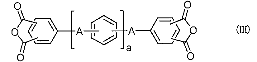
(式(III)中、aは0または1以上の自然数、Aは単結合(ビフェニル構造)、酸素原子(エーテル結合)、エステル結合のいずれかであり、全てが同じであっても、各々異なっていてもよい。酸無水物骨格(―CO-O-CO-)は、隣接する芳香環の結合部位から見て、芳香環の2,3位もしくは、3,4位に結合する。)
上記式(III)において、Aが単結合(ビフェニル構造)、酸素原子(エーテル結合)である酸二無水物としては、3,3’,4,4’-ビフェニルテトラカルボン酸二無水物、2,3,3’,4’-ビフェニルテトラカルボン酸二無水物、2,3,2’,3’-ビフェニルテトラカルボン酸二無水物、ビス(3,4-ジカルボキシフェニル)エーテル二無水物などが挙げられる。これらは、吸湿膨張係数を低減させる観点ならびに、ジアミンの選択性を広げる観点から、好ましい。
上記式(III)において、Aがエステル結合であるフェニルエステル系の酸二無水物は、ポリイミドを低吸湿にする観点から、特に好ましい。例えば、下記式で表わされる酸二無水物が挙げられる。具体的には、p-フェニレンビストリメリット酸モノエステル酸二無水物、p-ビフェニレンビストリメリット酸モノエステル酸二無水物などが挙げられる。これらは、吸湿膨張係数を低減させる観点ならびに、ジアミンの選択性を広げる観点から、特に好ましい。

(式中、aは0または1以上の自然数である。酸無水物骨格(―CO-O-CO-)は、隣接する芳香環の結合部位から見て、芳香環の2,3位もしくは3,4位に結合する。)
上述の吸湿膨張係数が小さいテトラカルボン酸二無水物の場合、後述するジアミンとしては幅広く選択することができる。
併用するテトラカルボン酸二無水物として、下記式で表わされるような少なくとも1つのフッ素原子を有するテトラカルボン酸二無水物を用いることができる。フッ素が導入されたテトラカルボン酸二無水物を用いると、最終的に得られるポリイミドの吸湿膨張係数が低下する。少なくとも1つのフッ素原子を有するテトラカルボン酸二無水物としては、中でも、フルオロ基、トリフルオロメチル基、またはトリフルオロメトキシ基を有することが好ましい。具体的には、2,2-ビス(3,4-ジカルボキシフェニル)-1,1,1,3,3,3-ヘキサフルオロプロパン二無水物などが挙げられる。しかしながら、上記ポリイミド成分として含まれるポリイミド前駆体がフッ素を含んだ骨格を有する場合、上記ポリイミド前駆体が、塩基性水溶液に溶解しづらい傾向にあり、上記ポリイミド前駆体の状態で、レジスト等を用いてパターニングを行う際には、アルコール等の有機溶媒と塩基性水溶液との混合溶液によって現像を行う必要がある場合がある。

ここで、選択されるジアミンは耐熱性、すなわち、低アウトガス化の観点より芳香族ジアミンが好ましいが、目的の物性に応じてジアミンの全体の60モル%、好ましくは40モル%を超えない範囲で、脂肪族ジアミンやシロキサン系ジアミン等の芳香族以外のジアミンを用いてもよい。
また、上記ポリイミド成分においては、上記式(I)中のR2のうち33モル%以上が下記式で表わされるいずれかの構造であることが好ましい。

(R3は2価の有機基、酸素原子、硫黄原子、またはスルホン基であり、R4およびR5は1価の有機基、またはハロゲン原子である。)
上記ポリイミドが上記式のいずれかの構造を含むと、これら剛直な骨格に由来し、低線熱膨張および低吸湿膨張を示す。さらには、市販で入手が容易であり、低コストであるというメリットもある。
上記のような構造を有する場合、上記ポリイミドの耐熱性が向上し、線熱膨張係数が小さくなる。そのため、上記式(I)中のR2のうち100モル%に近ければ近いほど好ましいが、上記式(I)中のR2のうち少なくとも33%以上含有すればよい。中でも上記式で表わされる構造の含有量は上記式(1)中のR2のうち50モル%以上であることが好ましく、さらに70モル%以上であることが好ましい。
上記のような構造を有する場合、上記ポリイミドの耐熱性が向上し、線熱膨張係数が小さくなる。そのため、上記式(I)中のR2のうち100モル%に近ければ近いほど好ましいが、上記式(I)中のR2のうち少なくとも33%以上含有すればよい。中でも上記式で表わされる構造の含有量は上記式(1)中のR2のうち50モル%以上であることが好ましく、さらに70モル%以上であることが好ましい。
上記ポリイミドをより低吸湿膨張とする観点からは、ジアミンの構造としては、下記式(IV-1)~(IV-3)、(V)で表わされるものが好ましい。

(式(IV-2)~(IV-3)中、同一の芳香環に2つアミノ基が結合していてもよい。式(V)中、aは0または1以上の自然数、アミノ基はベンゼン環同士の結合に対して、メタ位またはパラ位に結合する。また、芳香環上の水素原子の一部若しくは全てをフルオロ基、メチル基、メトキシ基、トリフルオロメチル基、またはトリフルオロメトキシ基から選ばれた置換基で置換されていてもよい。)
上記式(IV-1)~(IV-3)で表されるジアミンとしては、具体的には、p-フェニレンジアミン、m-フェニレンジアミン、1,4-ジアミノナフタレン、1,5-ジアミノナフタレン、2、6-ジアミノナフタレン、2,7-ジアミノナフタレン、1,4-ジアミノアントラセンなどが挙げられる。
上記式(V)で表わされるジアミンとしては、具体的には、2,2’-ジメチル-4,4’-ジアミノビフェニル、2,2’-ジトリフルオロメチル-4,4’-ジアミノビフェニル、3,3’-ジクロロ-4,4’-ジアミノビフェニル、3,3’-ジメトキシ-4,4’-ジアミノビフェニル、3,3’-ジメチル-4,4’-ジアミノビフェニル等が挙げられる。
また、芳香環の置換基としてフッ素を導入すると、上記ポリイミドの吸湿膨張係数を低減させることができる。例えば、上記式(V)で表わされるジアミンの中でフッ素が導入された構造としては、下記式で表わされるものが挙げられる。しかしながら、フッ素を含むポリイミド前駆体、特にポリアミック酸は、塩基性水溶液に溶解しにくく、基板上に低アウトガス感光性ポリイミド絶縁層を部分的に形成する場合には、上記絶縁層の加工の際に、アルコールなどの有機溶媒との混合溶液で現像する必要がある場合がある。

ポリイミドに感光性を付与し、感光性ポリイミドまたは感光性ポリイミド前駆体として用いる際には、感度を高め、マスクパターンを正確に再現するパターン形状を得るために、1μmの膜厚のときに、露光波長に対して少なくとも5%以上の透過率を示すことが好ましく、15%以上の透過率を示すことが更に好ましい。
また、一般的な露光光源である高圧水銀灯を用いて露光を行う場合には、少なくとも436nm、405nm、365nmの波長の電磁波のうち1つの波長の電磁波に対する透過率が、厚み1μmのフィルムに成膜した時で好ましくは5%以上、更に好ましくは15%、より更に好ましくは50%以上である。
露光波長に対してポリイミドの透過率が高いということは、それだけ、光のロスが少ないということであり、高感度の感光性ポリイミドまたは感光性ポリミド前駆体を得ることができる。
露光波長に対してポリイミドの透過率が高いということは、それだけ、光のロスが少ないということであり、高感度の感光性ポリイミドまたは感光性ポリミド前駆体を得ることができる。
ポリイミドとして、透過率を上げるためには、酸二無水物としてフッ素が導入された酸二無水物や、脂環骨格を有する酸二無水物を用いることが望ましい。しかし、脂環骨格を有する酸二無水物を用いると、耐熱性が低下し、低アウトガス性を損なう恐れがあるので、共重合割合に注意しながら併用してもよい。
本発明においては、透過率を上げるためには酸二無水物としてフッ素が導入された芳香族の酸二無水物を用いることが、耐熱性を維持しつつ(芳香族なので)、吸湿膨張も低減することが可能である点からさらに好ましい。
本発明においては、透過率を上げるためには酸二無水物としてフッ素が導入された芳香族の酸二無水物を用いることが、耐熱性を維持しつつ(芳香族なので)、吸湿膨張も低減することが可能である点からさらに好ましい。
本発明において用いられる少なくとも1つのフッ素原子を有するテトラカルボン酸二無水物としては、上述のフッ素原子を有するテトラカルボン酸二無水物を用いることができ、なかでも、フルオロ基、トリフルオロメチル基、またはトリフルオロメトキシ基を有することが好ましい。具体的には、2,2-ビス(3,4-ジカルボキシフェニル)-1,1,1,3,3,3-ヘキサフルオロプロパン二無水物などが挙げられる。
しかしながら、フッ素を含んだ骨格を有するポリイミド前駆体は、塩基性水溶液に溶解しづらい傾向にあり、ポリイミド前駆体の状態で、レジスト等を用いてパターニングを行う際には、アルコール等の有機溶媒と塩基性水溶液との混合溶液によって現像を行う必要がある場合がある。
しかしながら、フッ素を含んだ骨格を有するポリイミド前駆体は、塩基性水溶液に溶解しづらい傾向にあり、ポリイミド前駆体の状態で、レジスト等を用いてパターニングを行う際には、アルコール等の有機溶媒と塩基性水溶液との混合溶液によって現像を行う必要がある場合がある。
また、ピロメリット酸無水物、3,3’,4,4’-ビフェニルテトラカルボン酸二無水物、1,4,5,8-ナフタレンテトラカルボン酸二無水物などの剛直な酸二無水物を用いると、最終的に得られるポリイミドの線熱膨張係数が小さくなるが、透明性の向上を阻害する傾向があるので、共重合割合に注意しながら併用してもよい。
ポリイミドとして、透過率を上げるためには、ジアミンとしてフッ素が導入されたジアミンや、脂環骨格を有するジアミンを用いることが望ましい。しかし、脂環骨格を有するジアミンを用いると、耐熱性が低下し、低アウトガス性を損なう恐れがあるので、共重合割合に注意しながら併用してもよい。
透過率を上げるためにはジアミンとしてフッ素が導入された芳香族のジアミンを用いることが、耐熱性を維持しつつ(芳香族なので)、吸湿膨張も低減することが可能である点からさらに好ましい。
透過率を上げるためにはジアミンとしてフッ素が導入された芳香族のジアミンを用いることが、耐熱性を維持しつつ(芳香族なので)、吸湿膨張も低減することが可能である点からさらに好ましい。
フッ素が導入された芳香族のジアミンとしては、具体的には、上述のフッ素が導入された構造を有するものを挙げることができ、より具体的には、2,2’-ジトリフルオロメチル-4,4’-ジアミノビフェニル、2,2-ジ(3-アミノフェニル)-1,1,1,3,3,3-ヘキサフルオロプロパン、2,2-ジ(4-アミノフェニル)-1,1,1,3,3,3-ヘキサフルオロプロパン、2-(3-アミノフェニル)-2-(4-アミノフェニル)-1,1,1,3,3,3-ヘキサフルオロプロパン、1,3-ビス(3-アミノ-α,α-ジトリフルオロメチルベンジル)ベンゼン、1,3-ビス(4-アミノ-α,α-ジトリフルオロメチルベンジル)ベンゼン、1,4-ビス(3-アミノ-α,α-ジトリフルオロメチルベンジル)ベンゼン、1,4-ビス(4-アミノ-α,α-ジトリフルオロメチルベンジル)ベンゼン、2,2-ビス[3-(3-アミノフェノキシ)フェニル]-1,1,1,3,3,3-ヘキサフルオロプロパン、2,2-ビス[4-(4-アミノフェノキシ)フェニル]-1,1,1,3,3,3-ヘキサフルオロプロパン等が挙げられる。
しかしながら、フッ素を含むポリイミド前駆体、特にポリアミック酸は、塩基性水溶液に溶解しにくく、金属基材上に絶縁層を部分的に形成する場合には、上記絶縁層の加工の際に、アルコールなどの有機溶媒との混合溶液で現像する必要がある場合がある。
しかしながら、フッ素を含むポリイミド前駆体、特にポリアミック酸は、塩基性水溶液に溶解しにくく、金属基材上に絶縁層を部分的に形成する場合には、上記絶縁層の加工の際に、アルコールなどの有機溶媒との混合溶液で現像する必要がある場合がある。
一方、ジアミンとして、1,3-ビス(3-アミノプロピル)テトラメチルジシロキサンなどのシロキサン骨格を有するジアミンを用いると、金属基材との密着性を改善したり、上記ポリイミドの弾性率が低下し、ガラス転移温度を低下させたりすることができる。
ポリイミドまたはポリイミド前駆体のポリイミド成分を含有するポリイミド樹脂組成物を用いてポリイミドを含有する絶縁層を形成する場合、ポリイミド成分の重量平均分子量は、その用途にもよるが、3,000~1,000,000の範囲内であることが好ましく、5,000~500,000の範囲内であることがさらに好ましく、10,000~500,000の範囲内であることがさらに好ましい。重量平均分子量が3,000未満であると、塗膜又はフィルムとした場合に十分な強度が得られにくい。また、加熱処理等を施しポリイミドとした際の膜の強度も低くなる。一方、重量平均分子量が1,000,000を超えると粘度が上昇し、溶解性も落ちてくるため、表面が平滑で膜厚が均一な塗膜又はフィルムが得られにくい。
ここで用いている分子量とは、ゲル浸透クロマトグラフィー(GPC)によるポリスチレン換算の値のことをいい、ポリイミド前駆体そのものの分子量でもよいし、無水酢酸等で化学的イミド化処理を行った後のものでもよい。
ここで用いている分子量とは、ゲル浸透クロマトグラフィー(GPC)によるポリスチレン換算の値のことをいい、ポリイミド前駆体そのものの分子量でもよいし、無水酢酸等で化学的イミド化処理を行った後のものでもよい。
ポリイミド成分の含有量としては、得られるパターンの膜物性、特に膜強度や耐熱性の点から、上記ポリイミド樹脂組成物の固形分全体に対し、50重量%以上であることが好ましく、中でも、70重量%以上であることが好ましい。
なお、ポリイミド樹脂組成物の固形分とは溶剤以外の全成分であり、液状のモノマー成分も固形分に含まれる。
なお、ポリイミド樹脂組成物の固形分とは溶剤以外の全成分であり、液状のモノマー成分も固形分に含まれる。
本発明においては、絶縁層が上述のポリイミドを含有していればよく、必要に応じて適宜、このポリイミドと他の接着性を有するポリイミドとを積層したり組み合わせたりして、絶縁層として用いてもよい。
また、上述のポリイミドは、感光性ポリイミドまたは感光性ポリイミド前駆体を用いて得られるものであってもよい。感光性ポリイミドは、公知の手法を用いて得ることができる。例えば、ポリアミック酸のカルボキシル基にエステル結合やイオン結合でエチレン性二重結合を導入し、得られるポリイミド前駆体に光ラジカル開始剤を混合し、溶剤現像ネガ型感光性ポリイミド前駆体とすることができる。また例えば、ポリアミック酸やその部分エステル化物にナフトキノンジアジド化合物を添加し、アルカリ現像ポジ型感光性ポリイミド前駆体とする、あるいは、ポリアミック酸にニフェジピン系化合物を添加しアルカリ現像ネガ型感光性ポリイミド前駆体とするなど、ポリアミック酸に光塩基発生剤を添加し、アルカリ現像ネガ型感光性ポリイミド前駆体とすることができる。
これらの感光性ポリイミド前駆体には、ポリイミド成分の重量に対して15%~35%の感光性付与成分が添加されている。そのため、パターン形成後に300℃~400℃で加熱したとしても、感光性付与成分由来の残渣がポリイミド中に残存する。これらの残存物が線熱膨張係数や吸湿膨張係数を大きくする原因となることから、感光性ポリイミド前駆体を用いると、非感光性のポリイミド前駆体を用いた場合に比べて、EL素子の信頼性が低下する傾向にある。しかしながら、ポリアミック酸に光塩基発生剤を添加した感光性ポリイミド前駆体は、添加剤である光塩基発生剤の添加量を15%以下にしてもパターン形成可能であることから、ポリイミドとした後も添加剤由来の分解残渣が少なく、線熱膨張係数や吸湿膨張係数などの特性の劣化が少なく、さらにアウトガスも少ないため、本発明に適用可能な感光性ポリイミド前駆体としては最も好ましい。
ポリイミドに用いられるポリイミド前駆体は、塩基性水溶液によって現像可能であることが、金属基材上に絶縁層を部分的に形成する際に、作業環境の安全性確保およびプロセスコストの低減の観点から好ましい。塩基性水溶液は、安価に入手でき、廃液処理費用や作業安全性確保のための設備費用が安価であるため、より低コストでの生産が可能となる。
絶縁層には、必要に応じて、レベリング剤、可塑剤、界面活性剤、消泡剤等の添加剤が含有されていてもよい。
絶縁層の厚みとしては、絶縁性および熱伝導性を兼ね備えることができれば特に限定されるものではないが、具体的には、0.3μm~100μmの範囲内であることが好ましく、より好ましくは0.5μm~50μmの範囲内、さらに好ましくは1μm~20μmの範囲内である。絶縁層の厚みが薄すぎると十分な絶縁性が得られない場合があり、絶縁層の厚みが厚すぎると熱伝導性が低下するおそれがあるからである。
上記絶縁層除去部が、絶縁層の外縁より内側に形成されている場合、外縁側の絶縁層と中心部分側の絶縁層とに別れるが、この場合の外縁側絶縁層の膜厚と中心部分側絶縁層の膜厚は、同一であってもよく、また異なっていても良い。
例えば、外縁側絶縁層の膜厚を中心部分側絶縁層の膜厚より厚く形成することにより、封止した際に中心部分側絶縁層とバリア性基板との間にスペースを形成することが可能となり、電子素子を封止する際に好ましい場合がある等、外縁側絶縁層の膜厚と中心部分側絶縁層の膜厚とを異ならせることによる利点も考えられるが、絶縁層の製造面を考慮すると、同一の膜厚であることが好ましい。
上記絶縁層除去部が、絶縁層の外縁より内側に形成されている場合、外縁側の絶縁層と中心部分側の絶縁層とに別れるが、この場合の外縁側絶縁層の膜厚と中心部分側絶縁層の膜厚は、同一であってもよく、また異なっていても良い。
例えば、外縁側絶縁層の膜厚を中心部分側絶縁層の膜厚より厚く形成することにより、封止した際に中心部分側絶縁層とバリア性基板との間にスペースを形成することが可能となり、電子素子を封止する際に好ましい場合がある等、外縁側絶縁層の膜厚と中心部分側絶縁層の膜厚とを異ならせることによる利点も考えられるが、絶縁層の製造面を考慮すると、同一の膜厚であることが好ましい。
絶縁層は、吸湿剤を含有していてもよい。絶縁層中の吸湿剤による吸湿によって、外部からの水分の浸入をより有効に防ぐことができるからである。それにより、本発明の熱伝導性封止部材を用いてEL素子を作製した際には、素子性能の劣化をより一層抑制することができる。
吸湿剤としては、少なくとも水分を吸着する機能を有するものであれば特に限定されるものではないが、中でも、化学的に水分を吸着するとともに、吸湿しても固体状態を維持する化合物であることが好ましい。このような化合物としては、例えば、金属酸化物、金属の無機酸塩もしくは有機酸塩などを挙げることができる。特に、アルカリ土類金属酸化物および硫酸塩が好ましい。アルカリ土類金属酸化物としては、例えば、酸化カルシウム、酸化バリウム、酸化マグネシウム、酸化ストロンチウム等を挙げることができる。硫酸塩としては、例えば、硫酸リチウム、硫酸ナトリウム、硫酸ガリウム、硫酸チタン、硫酸ニッケル等を挙げることができる。また、シリカゲルや、ポリビニルアルコールなどの吸湿性を有する有機化合物も用いることができる。これらの中でも、酸化カルシウム、酸化バリウム、シリカゲルが特に好ましい。これらの吸湿剤は吸湿性が高いからである。
吸湿剤の含有量は、特に限定されるものではないが、吸湿剤とポリイミドの合計量100質量部に対して、5質量部~80質量部の範囲内であることが好ましく、より好ましくは5質量部~60質量部の範囲内、さらに好ましくは5質量部~50質量部の範囲内である。
絶縁層の形成方法としては、絶縁性を有する樹脂を所定の膜厚で形成できる方法であれば特に限定されるものではなく、一般的に用いられている方法を用いることができる。
本発明においては、上述したようにポリイミドを用いることが好ましいが、ポリイミドを用いる場合は、例えば、金属基材上にポリイミド溶液またはポリイミド前駆体溶液を塗布する方法を用いることができる。中でも、ポリイミド前駆体溶液を塗布する方法が好適である。一般にポリイミドは溶媒への溶解性に乏しいからである。また、溶媒への溶解性が高いポリイミドは、耐熱性、線熱膨張係数、吸湿膨張係数などの物性に劣るからである。
塗布方法としては、例えば、スピンコート法、ダイコート法、ディップコート法、バーコート法、グラビア印刷法、スクリーン印刷法などを用いることができる。
本発明においては、上述したようにポリイミドを用いることが好ましいが、ポリイミドを用いる場合は、例えば、金属基材上にポリイミド溶液またはポリイミド前駆体溶液を塗布する方法を用いることができる。中でも、ポリイミド前駆体溶液を塗布する方法が好適である。一般にポリイミドは溶媒への溶解性に乏しいからである。また、溶媒への溶解性が高いポリイミドは、耐熱性、線熱膨張係数、吸湿膨張係数などの物性に劣るからである。
塗布方法としては、例えば、スピンコート法、ダイコート法、ディップコート法、バーコート法、グラビア印刷法、スクリーン印刷法などを用いることができる。
また、金属基材と絶縁層との積層体を形成するに際しては、ポリイミドフィルムを利用することもできる。ポリイミドフィルムを利用する場合には、ポリイミドフィルム上に金属材料を蒸着することで、金属基材と絶縁層との積層体を得ることができる。
3.粘着層
本発明の熱伝導性封止部材は、上記絶縁層上に粘着層を有することが好ましい。粘着層を有することにより、電子素子上に本発明の熱伝導性封止部材を配置して積層する工程を容易に行うことができるからである。
本発明において、粘着層が形成される場合は、上記絶縁層除去部に粘着層が形成されていないことが好ましい。工程上簡便に上記絶縁層除去部に封止樹脂を配置して封止樹脂部を形成することができるからである。
このように粘着層の形成部位は、上記絶縁層除去部に形成されていなければ特に限定されるものではないが、図1に示すように、絶縁層と同様のパターンで形成されていることが好ましい。
本発明の熱伝導性封止部材は、上記絶縁層上に粘着層を有することが好ましい。粘着層を有することにより、電子素子上に本発明の熱伝導性封止部材を配置して積層する工程を容易に行うことができるからである。
本発明において、粘着層が形成される場合は、上記絶縁層除去部に粘着層が形成されていないことが好ましい。工程上簡便に上記絶縁層除去部に封止樹脂を配置して封止樹脂部を形成することができるからである。
このように粘着層の形成部位は、上記絶縁層除去部に形成されていなければ特に限定されるものではないが、図1に示すように、絶縁層と同様のパターンで形成されていることが好ましい。
本発明に用いられる粘着層は、耐熱性を有するものであることが好ましい。このような粘着層の耐熱性としては、本発明の熱伝導性封止部材の製造過程における加熱や、本発明の熱伝導性封止部材を用いてEL素子等の電子素子を封止する場合には、電子素子の製造過程における加熱および電子素子の発熱などに耐える程度であればよく、プロセス温度において粘着層からガスが発生しないことが好ましい。具体的には、粘着層を構成する粘着剤の5%重量減少温度が、80℃以上であることが好ましく、100℃以上であることがより好ましく、120℃以上であることがさらに好ましい。5%重量減少温度が上記範囲より小さいと、例えば電子素子がEL素子の場合、EL素子の発光時の発熱により粘着剤が分解し、その分解時に発生する物質によって素子特性を劣化させるおそれがある。また、熱劣化により粘着層自身の粘着性が低下し、素子との密着性が悪くなり、素子から剥離する場合がある。
なお、5%重量減少温度は、熱重量分析装置または示差熱天秤(例えばThermo Plus TG8120(リガク社製))を用い、窒素雰囲気下、10℃/分の昇温速度で昇温し、測定した値である。
なお、5%重量減少温度は、熱重量分析装置または示差熱天秤(例えばThermo Plus TG8120(リガク社製))を用い、窒素雰囲気下、10℃/分の昇温速度で昇温し、測定した値である。
粘着層は、本発明の耐熱性封止部材を用いて例えばEL素子を封止する際には透明電極層とEL層と背面電極層とを覆うように透明基板に接着されるものであり、凹凸追従性を備える。具体的には、粘着層の室温での貯蔵弾性率が、1.0×10²Pa以上1.0×10⁷Pa以下であることが好ましく、1.0×10³Pa以上1.0×10⁶Pa以下であることがさらに好ましく、1.0×10⁴Pa以上1.0×10⁶Pa以下であることが特に好ましい。なお、室温とは25℃をいう。粘着層の室温での貯蔵弾性率が上記範囲であれば、実用上十分な粘着性と良好な凹凸追従性が得られる。室温における貯蔵弾性率が上記範囲より小さい場合は、粘着層が脆弱なものとなり凝集破壊を起こしやすくなる。一方、上記範囲より大きい場合は、凹凸に対する十分な追従性が発現されにくい。貯蔵弾性率は硬さ・軟らかさの指標となるものであり、粘着層の室温での貯蔵弾性率が上記範囲であれば、例えばEL素子の場合には透明電極層とEL層と背面電極層とによる段差を十分に埋めることができる。
なお、貯蔵弾性率は、動的粘弾性測定装置(例えば、RSA3 (TAインスツルメンツ社製)を用い、周波数1Hz、昇温速度5℃/分の条件で測定した値である。
なお、貯蔵弾性率は、動的粘弾性測定装置(例えば、RSA3 (TAインスツルメンツ社製)を用い、周波数1Hz、昇温速度5℃/分の条件で測定した値である。
また、粘着層の凹凸追従性としては、粘着層を構成する粘着剤のガラス転移温度(Tg)が100℃以下であることが好ましく、より好ましくは50℃以下、さらに好ましくは30℃以下である。本発明の熱伝導性封止部材を用いて例えばEL素子を封止する場合、熱伝導性封止部材の粘着層をEL素子を支持する透明基板に貼り付ける際の温度が、粘着剤のTgよりも低いと、凹凸に追従することが困難となる。よって、粘着剤のTgは比較的低いことが好ましく、室温以下であることが特に好ましいのである。粘着剤のTgが上記範囲であれば、熱伝導性封止部材の粘着層をEL素子を支持する透明基板に貼り付ける際の温度を低くすることができる。
粘着層は、通常、絶縁性を有する。具体的に、絶縁層の体積抵抗は、1.0×10⁷Ω・m以上であることが好ましく、1.0×10⁸Ω・m以上であることがより好ましく、1.0×10⁹Ω・m以上であることがさらに好ましい。
なお、体積抵抗は、JIS K6911、JIS C2318、ASTM D257 などの規格に準拠する手法で測定することが可能である。
なお、体積抵抗は、JIS K6911、JIS C2318、ASTM D257 などの規格に準拠する手法で測定することが可能である。
粘着層に用いられる粘着剤としては、上述の特性を満たすものであり、かつ本発明の耐熱性封止部材をEL素子に用いる場合にはEL層に悪影響を及ぼさないものであれば特に限定されるものではなく、例えば、ポリイミド系樹脂、シリコーン系樹脂、エポキシ系樹脂、アクリル系樹脂などの熱硬化型樹脂、光硬化型樹脂や、ポリエチレン、ポリプロピレン等の酸変性物などの熱可塑性樹脂を挙げることができる。中でも、熱硬化型樹脂、光硬化型樹脂が好ましい。さらには、耐熱性の観点から、ポリイミド系樹脂、シリコーン系樹脂が好ましい。特に、非シリコーン系樹脂であることが好ましく、耐熱性および熱伝導性に優れることから、ポリイミド系樹脂が好適である。
また、粘着剤は硬化型粘着剤であってもよい。硬化型粘着剤とは、素子製造時は粘着性を有し、素子作製後に硬化するものをいう。硬化型粘着剤は、被封止物との密着性がより強固となる利点を有する。一方、本発明の熱伝導性封止部材をフレキシブルなEL素子に適用した場合、硬化型粘着剤を用いると、素子を屈曲させたときに粘着層の硬化した部分にクラックが発生し素子を劣化させる場合がある。硬化型粘着剤としては、上述の熱硬化型樹脂や光硬化型樹脂を用いることができる。
一般的なポリイミド系樹脂は、下記式(VI)で表される繰り返し単位を有する。

(式(VI)中、R6は4価の有機基、R7は2価の有機基、繰り返されるR6同士およびR7同士はそれぞれ同一であってもよく異なっていてもよい。nは1以上の自然数である。)
式(VI)において、一般に、R6は、テトラカルボン酸二無水物由来の構造であり、R7はジアミン由来の構造である。
式(VI)において、一般に、R6は、テトラカルボン酸二無水物由来の構造であり、R7はジアミン由来の構造である。
粘着性を創出する観点から、ポリイミド系樹脂に適用されるジアミンとしては、少なくとも脂肪族ジアミンを含むことが好ましい。ここで、脂肪族ジアミンとは、2つのアミノ基を連結する部位のアミノ基の窒素原子と結合する炭素原子が、脂肪族炭素であるものをいい、芳香族ジアミンとは、上記炭素原子が芳香族炭素であるものをいう。
同様に、テトラカルボン酸二無水物についても、2つの酸無水物基が接続する部位の構造が芳香族であるものが芳香族酸二無水物、脂肪族であるものが脂肪族酸二無水物という。
同様に、テトラカルボン酸二無水物についても、2つの酸無水物基が接続する部位の構造が芳香族であるものが芳香族酸二無水物、脂肪族であるものが脂肪族酸二無水物という。
ポリイミド系樹脂としては、下記式(1)で表されるテトラカルボン酸二無水物ならびに下記式(2)で表されるテトラカルボン酸および該テトラカルボン酸の誘導体から選ばれた1種以上の化合物からなるテトラカルボン酸成分と、下記式(3)で表される脂肪族ジアミンとをテトラカルボン酸成分のモル数が脂肪族ジアミンのモル数より過剰になるように配合して加熱反応させてポリイミド(A)とし、ポリイミド(A)と下記式(4)で表される芳香族ジアミンとを配合して加熱反応させて得られるポリイミド(B)を必須の成分とし、下記式(5)で表されるビスマレイミド化合物や、2官能エポキシ化合物、2官能アクリレートなどの2官能性の架橋剤を配合してなる熱硬化性ポリイミド樹脂組成物を硬化して得られるものであることが好ましい。

(式(1)中、R11は4価の有機基である。)
(式(2)中、R11は4価の有機基であり、Y1~Y4は独立して水素または炭素数1~8の炭化水素基である。)
(式(3)中、X1は、アミノ基に脂肪族基または脂環基が直接結合している炭素数1~221の2価の有機基であり、その構造の一部に芳香族基、エーテル基、その他の置換基を含んでいてもよい。)
(式(4)中、X2は、アミノ基に芳香族環が直接結合している炭素数6~27の2価の有機基であり、その構造の一部に脂肪族基、脂環基、その他の置換基を含んでいてもよい。)
(式(5)中、Zは2価の有機基である。)
ここで、式(VI)におけるR6は式(1)におけるR11であり、式(VI)におけるR7は式(3)におけるX1または式(4)におけるX2である。
すなわち、熱硬化性ポリイミド樹脂組成物およびポリイミド系樹脂は下記の工程(1)~(4)を含む方法により得られる。
・工程(1):テトラカルボン酸成分と脂肪族ジアミンとを加熱反応させてポリイミド(A)を合成する工程
・工程(2):工程(1)で合成したポリイミド(A)と芳香族ジアミンとを加熱反応させてポリイミド(B)を合成する工程
・工程(3):工程(2)で合成したポリイミド(B)と2官能性の架橋剤とを配合して室温で混合し、熱硬化性ポリイミド樹脂組成物を製造する工程
・工程(4):工程(3)で得られた熱硬化性ポリイミド樹脂組成物を加熱硬化させて、ポリイミド系樹脂を得る工程
・工程(1):テトラカルボン酸成分と脂肪族ジアミンとを加熱反応させてポリイミド(A)を合成する工程
・工程(2):工程(1)で合成したポリイミド(A)と芳香族ジアミンとを加熱反応させてポリイミド(B)を合成する工程
・工程(3):工程(2)で合成したポリイミド(B)と2官能性の架橋剤とを配合して室温で混合し、熱硬化性ポリイミド樹脂組成物を製造する工程
・工程(4):工程(3)で得られた熱硬化性ポリイミド樹脂組成物を加熱硬化させて、ポリイミド系樹脂を得る工程
上記式(1)のテトラカルボン酸二無水物のうち、脂肪族テトラカルボン酸二無水物としては、例えば、1,2,4,5-シクロヘキサンテトラカルボン酸二無水物、1,2,3,4-ブタンテトラカルボン酸二無水物、1,2,3,4-シクロブタンテトラカルボン酸二無水物、1,2,3,4-シクロペンタンテトラカルボン酸二無水物、ビシクロ[2.2.2]オクト-7-エン-2,3,5,6-テトラカルボン酸二無水物、ジシクロヘキシルテトラカルボン酸二無水物などを挙げることができる。
上記式(1)のテトラカルボン酸二無水物のうち、芳香族テトラカルボン酸二無水物としては、例えば、ピロメリット酸二無水物、3,3’,4,4’-ビフェニルテトラカルボン酸二無水物、2,3,3’,4’-ビフェニルテトラカルボン酸二無水物、2,2-ビス(3,4-ジカルボキシフェニル)プロパン二無水物、2,2-ビス(2,3-ジカルボキシフェニル)プロパン二無水物、2,2-ビス(3,4-ジカルボキシフェニル)-1,1,1,3,3,3-ヘキサフルオロプロパン二無水物、2,2-ビス(2,3-ジカルボキシフェニル)-1,1,1,3,3,3-ヘキサフルオロプロパン二無水物、ビス(3,4-ジカルボキシフェニル)スルホン二無水物、ビス(3,4-ジカルボキシフェニル)エーテル二無水物、ビス(2,3-ジカルボキシフェニル)エーテル二無水物、3,3’,4,4’-ベンゾフェノンテトラカルボン酸二無水物、2,2’,3,3’-ベンゾフェノンテトラカルボン酸二無水物、4,4’-(p-フェニレンジオキシ)ジフタル酸二無水物、4,4’-(m-フェニレンジオキシ)ジフタル酸二無水物、エチレンテトラカルボン酸二無水物、3-カルボキシメチル-1,2,4-シクロペンタントリカルボン酸二無水物、1,1-ビス(2,3-ジカルボキシフェニル)エタン二無水物、ビス(2,3-ジカルボキシフェニル)メタン二無水物、ビス(3,4-ジカルボキシフェニル)メタン二無水物等を挙げることができる。
上記式(2)のテトラカルボン酸、およびその誘導体のうち、脂肪族テトラカルボン酸、およびその誘導体としては、例えば、1,2,4,5-シクロヘキサンテトラカルボン酸、1,2,3,4-ブタンテトラカルボン酸、1,2,3,4-シクロブタンテトラカルボン酸、1,2,3,4-シクロペンタンテトラカルボン酸、ビシクロ[2.2.2]オクト-7-エン-2,3,5,6-テトラカルボン酸、ジシクロヘキシルテトラカルボン酸など、およびそれらと炭素数1~8のアルコールとのエステル類を挙げることができる。
上記式(2)のテトラカルボン酸、およびその誘導体うち、芳香族テトラカルボン酸、およびその誘導体としては、例えば、ピロメリット酸、3,3’,4,4’-ビフェニルテトラカルボン酸、2,3,3’,4’-ビフェニルテトラカルボン酸、2,2-ビス(3,4-ジカルボキシフェニル)プロパン、2,2-ビス(2,3-ジカルボキシフェニル)プロパン、2,2-ビス(3,4-ジカルボキシフェニル)-1,1,1,3,3,3-ヘキサフルオロプロパン、2,2-ビス(2,3-ジカルボキシフェニル)-1,1,1,3,3,3-ヘキサフルオロプロパン、ビス(3,4-ジカルボキシフェニル)スルホン、ビス(3,4-ジカルボキシフェニル)エーテル、ビス(2,3-ジカルボキシフェニル)エーテル、3,3’,4,4’-ベンゾフェノンテトラカルボン酸、2,2’,3,3’-ベンゾフェノンテトラカルボン酸、4,4’-(p-フェニレンジオキシ)ジフタル酸、4,4’-(m-フェニレンジオキシ)ジフタル酸、エチレンテトラカルボン酸、3-カルボキシメチル-1,2,4-シクロペンタントリカルボン酸、1,1-ビス(2,3-ジカルボキシフェニル)エタン、ビス(2,3-ジカルボキシフェニル)メタン、ビス(3,4-ジカルボキシフェニル)メタン等およびそれらと炭素数1~8のアルコールとのエステル類が挙げられる。
これらテトラカルボン酸無水物、テトラカルボン酸および該テトラカルボン酸の誘導体のうち、シクロヘキサンから誘導される構造を持つものまたはベンゼンから誘導される構造をもつものが好ましく、より好ましくはシクロヘキサンから誘導される構造を持つものが好ましく、特に好ましいのは1,2,4,5-シクロヘキサンテトラカルボン酸二無水物または1,2,4,5-シクロヘキサンテトラカルボン酸が挙げられ、これらは1種類単独かあるいは2種類以上を混合して使用することができる。
上記式(3)の脂肪族ジアミンはアミノ基に脂肪族基または脂環基が直接結合しているジアミンである。式(3)の脂肪族ジアミンのX1は、炭素数1~221の2価の有機基であることが好ましく、その構造の一部に芳香族基、エーテル基、その他の置換基を含んでいてもよい。特に脂肪族ジアミンがポリオキシアルキレンジアミンであると、可撓性に加え粘着性が得られて好ましい。なお、ここでいう粘着性とは、水、溶剤、熱などを使用せず、常温で短時間、わずかな圧力を加えるだけで接着する性質を指し、粘着力とは、試験片を常温で短時間被着体にわずかな圧力をかけて接触させた後、引き剥がす時に必要な力を指す。
ポリオキシアルキレンジアミンとしては、例えば下記式(7)で表されるようなポリオキシプロピレンジアミン、下記式(8)で表されるようなポリオキシエチレンジアミン、下記式(9)で表されるようなポリオキシブチレンジアミン及びこれらの共重合体が挙げられ、式(7)のポリオキシプロピレンジアミンまたは共重合体として下記式(6)で表されるプロピレンオキシドとエチレンオキシドに由来する骨格を含有するポリオキシアルキレンジアミンが良好な粘着性を持つポリイミド系樹脂を得る上で好ましい。

(式(6)中、a、cはプロピレンオキシド単位の重合度、bはエチレンオキシド単位の重合度である。)
(式(7)中、n1はプロピレンオキシド単位の重合度である。)
(式(8)中、n2はエチレンオキシド単位の重合度である。)
(式(9)中、n3はブチレンオキシド単位の重合度である。)
(式(7)中、n1はプロピレンオキシド単位の重合度である。)
(式(8)中、n2はエチレンオキシド単位の重合度である。)
(式(9)中、n3はブチレンオキシド単位の重合度である。)
ポリオキシアルキレンジアミンは、良好な粘着性を持つポリイミド系樹脂を得る上で、それぞれ次のような分子量であることが好ましい。上記式(6)のポリオキシアルキレンジアミンの分子量は好ましくは300~4000(プロピレンオキシドの重合度(a+c)が1.0~9.4(cは0ではない)、エチレンオキシドの重合度(b)が3.7~79.8)であり、より好ましくは600~2000(プロピレンオキシドの重合度(a+c)が3.6~6.0(cは0ではない)、エチレンオキシドの重合度(b)が9.0~38.7)である。上記式(7)のポリオキシプロピレンジアミンの分子量は好ましくは230~4000(プロピレンオキシドの重合度n1が2.6~68.0)であり、より好ましくは600~2000(プロピレンオキシドの重合度n1が8.7~33.0)である。上記式(8)のポリオキシエチレンジアミンの分子量は好ましくは300~4000(エチレンオキシドの重合度n2が5.5~89.5)であり、より好ましくは600~2000(エチレンオキシドの重合度n2が12.3~44.1)である。上記式(9)のポリオキシブチレンジアミンの分子量は好ましくは200~4000(ブチレンオキシドの重合度n3が1.6~54.3)であり、より好ましくは600~2000(ブチレンオキシドの重合度n3が7.1~26.6)である。
上記式(3)の脂肪族ジアミンのうち、ポリオキシアルキレンジアミン以外のジアミンとしては、例えば、4,4’-ジアミノジシクロヘキシルメタン、イソホロンジアミン、エチレンジアミン、テトラメチレンジアミン、ノルボルナンジアミン、パラキシリレンジアミン、1,3-ビス(アミノメチル)シクロヘキサン、1,3-ジアミノシクロヘキサン、ヘキサメチレンジアミン、メタキシリレンジアミン、4,4’-メチレンビス(シクロヘキシルアミン)、ビシクロヘキシルジアミン、シロキサンジアミン類などを挙げることができる。中でも、高分子量化が容易で、耐熱性に優れるという点で、4,4’-ジアミノジシクロヘキシルメタン、イソホロンジアミン、1,3-ジアミノシクロヘキサン等の脂環構造を有するジアミンを用いることが好ましい。これらのジアミンは単独あるいは2種以上を混合して使用することができる。
上記工程(1)の反応生成物であるポリイミド(A)は、脂肪族ジアミンにテトラカルボン酸二無水物またはテトラカルボン酸もしくは該テトラカルボン酸の誘導体から選ばれた1種以上の化合物からなるテトラカルボン酸成分を添加し、イミド化反応させる方法により得られる。
上記工程(1)の反応生成物であるポリイミド(A)は、上記式(1)で表されるテトラカルボン酸二無水物または上記式(2)で表されるテトラカルボン酸もしくは該テトラカルボン酸の誘導体から選ばれた1種以上の化合物からなるテトラカルボン酸成分を上記式(3)で表される脂肪族ジアミン1モルに対して好ましくは1.01モル以上2モル以下の比、より好ましくは1.5モル以上2モル以下の比で配合して合成するのが好ましい。この際、反応生成物の両末端に酸無水物基またはイミド形成可能なジカルボン酸誘導体の基を配することが好ましい。テトラカルボン酸成分を脂肪族ジアミン1モルに対して1モル以下の比で配合すると、上記工程(1)の反応生成物の両末端はテトラカルボン酸成分に由来する基とならないものが多くなり、後述する芳香族ジアミンと反応させることにおいて好ましくない。テトラカルボン酸成分の1種以上を脂肪族ジアミン1モルに対して2モルより大きい比で配合すると、未反応のテトラカルボン酸成分が多く残り、モノマー成分が残留することになり、耐熱性を低下させるおそれがある。
上記ポリイミド(A)は、無溶剤下で熱イミド化反応を行うことで得られるが、各種の有機溶媒を用いてもよい。具体的にはN,N-ジメチルアセトアミド、N-メチル-2-ピロリドン、N,N-ジメチルホルムアミド、ジメチルスルホキシド、ヘキサメチルホスホルアミド、テトラメチレンスルホン等の1種又は2種以上の溶媒を使用できる。特に、N-メチル-2-ピロリドン、N,N-ジメチルアセトアミドを溶媒に用いることが好ましい。また、共沸脱水を行うために、キシレンまたはトルエンを加えてもよい。ポリイミド(A)合成後は、テトラヒドロフラン、アセトン、メタノール等の低沸点溶媒で希釈することもできる。
脂肪族ジアミンは必要に応じて上記したような有機溶媒に溶解して使用してもよい。イミド化反応の反応温度は、150~200℃が好ましく、特に180~200℃が好ましい。150℃より低いと高分子量化が十分に行われず実用的なポリイミドが合成できない。200℃より高いとコストの問題で経済的に好ましくない。反応時間は1~12時間が好ましく、特に3~6時間が好ましい。1時間より短いと高分子量化が十分に行われず実用的なポリイミドが合成できない。12時間より長いとコストの問題で経済的に好ましくない。また、共沸溶剤としてトルエンあるいはキシレンを添加してイミド化反応を行ってもよい。ポリイミドの生成はIRスペクトルによる1770および1700cm-1付近のイミド環の特性吸収によって確認することができる。
上記工程(2)のポリイミド(B)は、上記工程(1)で得られたポリイミド(A)に芳香族ジアミンを配合しイミド化反応させる方法により得られる。上記式(4)で表される芳香族ジアミンをポリイミド(A)を製造する際に用いた脂肪族ジアミン1モルに対して好ましくは0.02モル以上2モル以下の比、より好ましくは1モル以上2モル以下の比で配合して合成する。この際、ポリイミド(B)の両末端に芳香族アミノ基を配するのが好ましい。芳香族ジアミンを脂肪族ジアミン1モルに対して2モルより大きい比で配合すると、未反応の芳香族ジアミンの割合が多くなり、この後の工程で得られるポリイミド系樹脂の可撓性が低くなる。
上記式(4)の芳香族ジアミンは、アミノ基に芳香族環が直接結合しているジアミンである。X2は炭素数6~27の2価の有機基であることが好ましく、その構造の一部に脂肪族基、脂環基、その他の置換基を含んでいてもよい。上記式(4)の芳香族ジアミンとしては、例えば、3,4’-ジアミノジフェニルエーテル、4,4’-ジアミノジフェニルエーテル、4,4’-ジアミノジフェニルメタン、4,4’-ジアミノジフェニルスルホン、m-フェニレンジアミン、p-フェニレンジアミン、2,4-トルエンジアミン、ジアミノベンゾフェノン、2,6-ジアミノナフタレン、1,5-ジアミノナフタレン、1,4-ビス(4-アミノフェノキシ)ベンゼン、1,3-ビス(4-アミノフェノキシ)ベンゼン、1,3-ビス(3-アミノフェノキシ)ベンゼン、4,4’-ビス(4-アミノフェノキシ)ビフェニル、α、α’-ビス(3-アミノフェニル)-1,4-ジイソプロピルベンゼン、ビス[4-(4-アミノフェノキシ)フェニル]スルホン、ビス[4-(3-アミノフェノキシ)フェニル]スルホン、α、α’―ビス(4-アミノフェニル)-1,4-ジイソプロピルベンゼンおよび2,2-ビス(4-アミノフェノキシフェニル)プロパン等が挙げられる。これらのうち、好ましいのは4,4’-ジアミノジフェニルエーテルが挙げられ、これらは1種類単独かあるいは2種類以上を混合して使用することができる。
上記ポリイミド(B)は、無溶剤下で熱イミド化反応を行うことで得られるが、各種の有機溶媒を用いてもよい。具体的にはN,N-ジメチルアセトアミド、N-メチル-2-ピロリドン、N,N-ジメチルホルムアミド、ジメチルスルホキシド、ヘキサメチルホスホルアミド、テトラメチレンスルホン等の高沸点溶媒、テトラヒドロフラン、アセトン等の低沸点溶媒の1種又は2種以上を使用できる。特に、N-メチル-2-ピロリドン、N,N-ジメチルアセトアミドを溶媒に用いることが好ましい。また、共沸脱水を行うために、キシレンまたはトルエンを加えてもよい。ポリイミド(B)合成後は、テトラヒドロフラン、アセトン、メタノール等の低沸点溶媒で希釈することもできる。
芳香族ジアミンは必要に応じて上記したような有機溶媒に溶解させて使用してもよい。イミド化反応の反応温度は、150~200℃が好ましく、特に180~200℃が好ましい。150℃より低いと高分子量化が十分に行われず実用的なポリイミドが合成できない。200℃より高いとコストの問題で経済的に好ましくない。反応時間は1~12時間が好ましく、特に3~6時間が好ましい。1時間より短いと高分子量化が十分に行われず実用的なポリイミドが合成できない。12時間より長いとコストの問題で経済的に好ましくない。また、共沸溶剤としてトルエンあるいはキシレンを添加してイミド化反応を行ってもよい。
熱硬化性ポリイミド樹脂組成物は、ポリイミド(B)と2官能性の架橋剤とを配合して室温で混合することにより得られる。2官能性の架橋剤としては、耐熱性の観点から、上記式(5)で表されるビスマレイミド化合物または2官能エポキシ化合物であることが好ましい。
上記式(5)のビスマレイミド化合物は以下のものが挙げられる。N,N’-(4,4’-ジフェニルメタン)ビスマレイミド、N,N’-(4,4’-ジフェニルオキシ)ビスマレイミド、N,N’-(4,4’-ジフェニルスルホン)ビスマレイミド、N,N’-p-フェニレンビスマレイミド、N,N’-m-フェニレンビスマレイミド、N,N’-2,4-トリレンビスマレイミド、N,N’-2,6-トリレンビスマレイミド、N,N’-エチレンビスマレイミド、N,N’-ヘキサメチレンビスマレイミド、N,N’-{4,4’-[2,2’-ビス(4’’,4’’’-フェノキシフェニル)イソプロピリデン]}ビスマレイミド、N,N’-{4,4’-[2,2’-ビス(4’’,4’’’-フェノキシフェニル)ヘキサフルオロイソプロピリデン]}ビスマレイミド、N,N’-[4,4’-ビス(3,5-ジメチルフェニル)メタン]ビスマレイミド、N,N’-[4,4’-ビス(3,5-ジエチルフェニル)メタン]ビスマレイミド、N,N’-[4,4’-(3-メチル-5-エチルフェニル)メタン]ビスマレイミド、N,N’-[4,4’-ビス(3,5-ジイソプロピルフェニル)メタン]ビスマレイミド、N,N’-(4,4’-ジシクロヘキシルメタン)ビスマレイミド、N,N’-p―キシリレンビスマレイミド、N,N’-m―キシリレンビスマレイミド、N,N’-(1,3-ジメチレンシクロヘキサン)ビスマレイミド、N,N’-(1,4-ジメチレンシクロヘキサン)ビスマレイミド等である。また、ポリオキシアルキレンジアミンの両末端が無水マレイン酸で封止されたビスマレイミド化合物を用いることもできる。例えば、ポリオキシエチレンジアミンの両末端が無水マレイン酸で封止されたビスマレイミド化合物、ポリオキシプロピレンジアミンの両末端が無水マレイン酸で封止されたビスマレイミド化合物、ポリオキシブチレンジアミンの両末端が無水マレイン酸で封止された化合物が挙げられる。この中で好ましいのは下記式(10)で表されるN,N’―(4,4’―ジフェニルメタン)ビスマレイミド、下記式(11)のN,N’-[4,4’-ビス(3-メチル-5-エチルフェニル)メタン]ビスマレイミドである。

上記工程(3)の熱硬化性ポリイミド樹脂組成物の製造の際に、上記式(5)で表されるビスマレイミド化合物をポリイミド(A)を製造する際に用いた脂肪族ジアミン1モルに対して好ましくは0.25モル以上4モル以下の比、より好ましくは0.75モル以上2モル以下の比で配合すると、可撓性のあるポリイミド系樹脂を与える熱硬化性ポリイミド樹脂組成物が得られる。ビスマレイミド化合物をポリイミド(A)を製造する際に用いた脂肪族ジアミン1モルに対して0.25モルより小さい比で配合すると、ポリイミド系樹脂の架橋密度が低く強度不足となる。テトラカルボン酸成分を脂肪族ジアミン1モルに対して1.01モル以上2モル以下の比で配合し、芳香族ジアミンを脂肪族ジアミン1モルに対して0.02モル以上2モル以下の比で配合し、ビスマレイミド化合物を脂肪族ジアミン1モルに対して4モルより大きい比で配合すると、ポリイミド系樹脂の可撓性が低くなる。
上記工程(3)の熱硬化性ポリイミド樹脂組成物の製造に用いる溶媒としては、N,N-ジメチルアセトアミド、N-メチル-2-ピロリドン、N,N-ジメチルホルムアミド、ヘキサメチルホスホルアミド等のアミド系溶媒、メチルエチルケトン、アセトン等のケトン系溶媒、1,4-ジオキサン、テトラヒドロフラン等の環状エーテル系溶媒、他にアセトニトリル等が挙げられる。特に、N,N-ジメチルアセトアミド、N-メチル-2-ピロリドン、N,N-ジメチルホルムアミド、ヘキサメチルホスホルアミド等のアミド系溶媒を用いることが好ましい。
上記工程(3)の熱硬化性ポリイミド樹脂組成物は次の方法で得られる。上記工程(2)で得られたポリイミド(B)と2官能性の架橋剤とを溶媒に溶かして均一な液になるまで混合する。熱硬化性ポリイミド樹脂組成物における溶媒の量は、キャスト製膜が可能な粘度となる量であることが好ましい。混合温度は0℃~80℃の範囲内が好ましく、20℃~60℃の範囲内がより好ましい。混合温度が0℃より低いと、2官能性の架橋剤が溶けにくく、均一な液になりにくい。混合温度が80℃より高いと、混合中に液状から固体状へと硬化する。
粘着性を有するポリイミド系樹脂は、得られた熱硬化性ポリイミド樹脂組成物を熱硬化させればよく、絶縁層が形成された金属基材上または剥離層上にキャストして膜状とし、熱硬化させると、ポリイミド系樹脂を含有する粘着層が得られる。硬化温度は、150℃~250℃の範囲内が好ましい。150℃より低いと未硬化の部分が残り粘着力が高くなりすぎて、粘着層に剥離層を貼り付けた後、剥がす時に凝集破壊が起きて糊残りが発生する。250℃より高いとコストの問題で経済的に好ましくない。硬化時間は0.5時間~10時間の範囲内が好ましい。0.5時間より短いと未硬化の部分が残り、粘着力が高くなりすぎて、粘着層に剥離層を貼り付けた後、剥がす時に凝集破壊が起きて糊残りが発生する。10時間より長いとコストの問題で経済的に好ましくない。
また、粘着層に用いられる樹脂組成物を後硬化させる場合には、樹脂組成物が、粘着層の形成過程での脱水ベークの際に硬化反応が開始するような添加剤を含有していることが好ましい。このような添加剤としては、例えば熱塩基発生剤または光塩基発生剤が挙げられる。
粘着層は、酸化防止剤を含有していてもよい。酸化防止剤の添加量が多くなると粘着層の耐熱性が向上するものの、粘着層中の酸化防止剤のEL層への移行などによりEL素子の信頼性低下を招く可能性も大きくなる。そのため、酸化防止剤の含有量は耐熱性とのバランスにおいてできる限り少ないほうがよい。
粘着層は、吸湿剤を含有していてもよい。粘着層中の吸湿剤による吸湿によって、外部からの水分の浸入をより有効に防ぐことができるからである。それにより、本発明の熱伝導性封止部材を用いてEL素子を作製した際には、素子性能の劣化をより一層抑制することができる。
なお、吸湿剤については、上記絶縁層の項に記載したものと同様であるので、ここでの説明は省略する。
なお、吸湿剤については、上記絶縁層の項に記載したものと同様であるので、ここでの説明は省略する。
吸湿剤の含有量は、特に限定されるものではないが、吸湿剤と樹脂の合計量100質量部に対して、5質量部~80質量部の範囲内であることが好ましく、より好ましくは5質量部~60質量部の範囲内、さらに好ましくは5質量部~50質量部の範囲内である。
粘着層中の吸湿剤の含有量は、均一であってもよく不均一であってもよい。中でも、粘着層の外縁部のみに吸湿剤が含有されていることが好ましい。本発明の耐熱性封止部材を用いて例えばEL素子を封止する際に、背面電極層と接する粘着層の部分に吸湿剤が含有されていると、吸湿剤によって粘着層表面が荒れ、EL層にダメージを与えるおそれがあるからである。すなわち、本発明の耐熱性封止部材を用いて例えばEL素子を封止する際、背面電極層と接しない粘着層の部分に吸湿剤が含有されていることが好ましい。
また、粘着層は、白色反射層としての機能を有してもよい。本発明の熱伝導性封止部材をEL素子に用いた場合には、EL層からの発光が白色反射層である粘着層表面で拡散反射されるため、干渉効果により発光色の角度依存性を緩和することができるからである。
粘着層の厚みは、凹凸追従性および熱伝導性を兼ね備えることができれば特に限定されるものではなく、具体的には、0.1μm~30μmの範囲内であることが好ましく、より好ましくは0.5μm~20μmの範囲内、さらに好ましくは1μm~10μmの範囲内である。粘着層の厚みが薄すぎると十分な凹凸追従性が得られない場合があり、粘着層の厚みが厚すぎると熱伝導性が低下するおそれがあるからである。
粘着層の形成方法としては、樹脂組成物を塗布する方法を用いることができる。樹脂組成物を塗布する際には、絶縁層上に塗布してもよく、後述する剥離層上に塗布してもよい。また、後述するように加工用シートを型抜きする方法を採用する場合には、剥離シート上に樹脂組成物を塗布する。塗布方法としては、均一な厚みで塗布することができる方法であれば特に限定されるものではなく、例えば、スピンコート法、ダイコート法、ディップコート法、バーコート法、グラビア印刷法、スクリーン印刷法などを用いることができる。
4.金属基材
本発明における金属基材は、上記の絶縁層および粘着層を支持するものである。
本発明における金属基材は、上記の絶縁層および粘着層を支持するものである。
金属基材の線熱膨張係数としては、寸法安定性の観点から、0ppm/℃~25ppm/℃の範囲内であることが好ましく、より好ましくは0ppm/℃~18ppm/℃の範囲内、さらに好ましくは0ppm/℃~12ppm/℃の範囲内、特に好ましくは0ppm/℃~7ppm/℃の範囲内である。なお、上記線熱膨張係数の測定方法については、金属箔を幅5mm×長さ20mmに切断し、評価サンプルとする以外は、上記絶縁層の線熱膨張係数の測定方法と同様である。
金属基材を構成する金属材料としては、例えば、アルミニウム、銅、銅合金、リン青銅、ステンレス鋼(SUS)、金、金合金、ニッケル、ニッケル合金、銀、銀合金、スズ、スズ合金、チタン、鉄、鉄合金、亜鉛、モリブデン等が挙げられる。中でも、大型の素子に適用する場合、SUSが好ましい。SUSは、耐久性、耐酸化性、耐熱性に優れている上、銅などに比べ線熱膨張係数が小さく寸法安定性に優れる。また、SUS304およびSUS430が入手しやすいという利点もある。放熱性という観点では、銅やアルミニウムが好ましいが、銅については酸化し変質しやすい、アルミニウムについては耐熱性が低く耐薬品性に劣る部分があり、プロセスが制限されるという課題もある。
金属基材の形状としては、特に限定されるものではなく、例えば、箔状や板状であってもよく、図6に例示するように金属基材2の形状が空気との接触面に凹凸を有する形状であってもよい。
金属基材が空気との接触面に凹凸を有する場合には、熱拡散が良好となり、放熱性を高めることができる。凹凸の形成方法としては、例えば金属基材の表面に直接、エンボス加工、エッチング加工、サンドブラスト加工、フロスト加工、スタンプ加工などの加工を施す方法、フォトレジスト等を用いて凹凸パターンを形成する方法、めっき方法、箔状や板状等の金属層と表面に凹凸を有する金属層とを貼り合わせる方法が挙げられる。エンボス加工の場合、例えば表面に凹凸を有する圧延ロールを用いてもよい。エッチング加工の場合、金属基材の種類に応じて薬剤が選択される。箔状や板状等の金属層と表面に凹凸を有する金属層とを貼り合わせる方法の場合、例えば、ロウ付け、溶接、半田等により金属層同士を接合する、あるいは、エポキシ樹脂等の接着剤を介して金属層同士を貼り合わせることができる。この場合、箔状や板状等の金属層と表面に凹凸を有する金属層とは、同じ金属材料で構成されていてもよく、異なる金属材料で構成されていてもよい。中でも、コスト面から、エンボス加工、エッチング加工が好ましく用いられる。
凹凸の寸法や形状としては、金属基材の空気との接触面における表面積を増やすことができれば特に限定されるものではない。凹凸の幅、高さ、ピッチ等としては、金属基材の種類や熱伝導性封止部材の用途等に応じて適宜選択され、例えばシミュレーションにより熱伝導に好適な範囲を求めることができる。
金属基材の厚みとしては、熱伝導性を備えることができれば特に限定されるものではなく、本発明の熱伝導性封止部材の用途に応じて適宜選択される。金属基材の厚みが厚いほど、面方向への熱拡散に優れたものとなる。一方、金属基材の厚みが薄いほど、可撓性に富んだものとなる。例えば本発明の熱伝導性封止部材が可撓性を有する場合には、熱伝導性および可撓性を兼ね備えることができればよく、具体的には、1μm~1000μmの範囲内であることが好ましく、より好ましくは2μm~300μmの範囲内、さらに好ましくは5μm~50μmの範囲内である。金属基材の厚みが薄すぎると、放熱機能を十分に発揮できなかったり、水蒸気に対するガスバリア性が低下したりする。また、金属基材の厚みが厚すぎると、フレキシブル性が低下したり、過重になったり、コスト高になったりする。
金属基材の作製方法としては、一般的な方法を用いることができ、金属材料の種類や金属基材の厚みなどに応じて適宜選択される。例えば、金属基材単体を得る方法であってもよく、ポリイミドフィルムからなる絶縁層上に金属材料を蒸着し、金属基材と絶縁層との積層体を得る方法であってもよい。中でも、ガスバリア性の観点から、金属基材単体を得る方法が好ましい。金属基材単体を得る方法の場合であって、金属基材が金属箔である場合、金属箔は圧延箔であってもよく電解箔であってもよいが、ガスバリア性が良好であることから、圧延箔が好ましい。
5.剥離層
本発明においては、上記粘着層上に剥離層が形成されていることが好ましい。本発明の熱伝導性封止部材の取り扱いが容易になるからである。
本発明においては、上記粘着層上に剥離層が形成されていることが好ましい。本発明の熱伝導性封止部材の取り扱いが容易になるからである。
剥離層はガスバリア性を有することが好ましい。絶縁層や粘着層の吸湿を抑制することができ、本発明の熱伝導性封止部材を安定して保管することができるからである。剥離層のガスバリア性としては、本発明の熱伝導性封止部材を例えば有機EL素子の封止に用いるまでの間、絶縁層や粘着層の吸湿を抑制することができる程度のガスバリア性であればよい。具体的には、剥離層が水に対してバリア性を有することが好ましく、剥離層の水蒸気透過率が1.0×10⁻¹g/m2/day以下であればよく、好ましくは1.0×10-3g/m2/day以下、より好ましくは1.0×10-5g/m2/day以下である。なお、水蒸気透過率は、水蒸気透過率測定装置パーマトラン3/31(米国MOCON社製)を用い、40℃100%Rhの条件で測定した値である。
剥離層としては、剥離性を有し、所定のガスバリア性を満たすものであれば特に限定されるものではなく、例えば、基材フィルム上にガスバリア層が形成された積層体、金属箔、フィルム単体、共押し出しフィルムを挙げることができる。
基材フィルムの材料としては、フィルム化することが可能なものであれば特に限定されるものではなく、例えば、ポリエチレン系樹脂、ポリプロピレン系樹脂、環状ポリオレフィン系樹脂、シンジオタクチックポリスチレン樹脂等のポリスチレン系樹脂、アクリロニトリル-スチレン共重合体(AS樹脂)、アクリロニトリル-ブタジエン-スチレン共重合体(ABS樹脂)、ポリ塩化ビニル系樹脂、フッ素系樹脂、ポリ(メタ)アクリル系樹脂、ポリカーボネート系樹脂、ポリエチレンテレフタレートまたはポリエチレンナフタレート等のポリエステル系樹脂、各種のナイロン等のポリアミド系樹脂、ポリイミド系樹脂、ポリアミドイミド系樹脂、ポリアリ-ルフタレート系樹脂、シリコーン系樹脂、ポリスルホン系樹脂、ポリフェニレンスルフィド系樹脂、ポリエーテルスルホン系樹脂、ポリウレタン系樹脂、アセタール系樹脂、セルロース系樹脂、その他等の各種の樹脂を挙げることができる。また、これらの樹脂に有機物または無機物の微粒子や粉体を混合したコンポジット材料などを用いてもよい。
基材フィルムの厚みとしては、剥離性が得られる厚みであれば特に限定されるものではなく、一般的なガスバリア性フィルムにおける基材フィルムの厚みと同程度とすることができる。基材フィルムの厚みが厚いとフレキシブル性が低下し、基材フィルムの厚みが薄いと基材フィルムを構成する材料にもよるが強度に劣る可能性がある。
ガスバリア層の材料としては、ガスバリア性を有するものであれば特に限定されるものではなく、無機材料および有機材料のいずれも用いることができる。
ガスバリア層に用いられる無機材料としては、例えば、無機酸化物、無機酸化窒化物、無機窒化物、金属を挙げることができる。これらは1種または2種以上を組み合わせて使用することができる。無機酸化物としては、酸化ケイ素、酸化アルミニウム、酸化マグネシウム、酸化チタン、酸化スズ、酸化インジウム合金が挙げられる。無機酸化窒化物としては、酸化窒化ケイ素が挙げられる。無機窒化物としては、窒化ケイ素、窒化アルミニウム、窒化チタンが挙げられる。金属としては、アルミニウム、銀、錫、クロム、ニッケル、チタンが挙げられる。無機材料として窒化物を含む材料を利用すると、粘着層に対して離型性を示す場合が多く、ガスバリア性と離型性を兼ね備えた材料として使用できる。
一方、ガスバリア層に用いられる有機材料としては、例えば、エポキシ/シリケート、ポリビニルアルコール(PVA)、エチレン-ビニルアルコール共重合体(EVOH)を挙げることができる。PVAおよびEVOHは単独または混合物で使用することができる。
ガスバリア層は、単層であってもよく複数層が積層されたものであってもよい。
ガスバリア層の厚みとしては、剥離性およびガスバリア性が得られる厚みであれば特に限定されるものではなく、ガスバリア層の材料に応じて適宜選択され、一般的なガスバリア性フィルムにおけるガスバリア層と同程度とすることができる。ガスバリア層の厚みが厚いとフレキシブル性が低下したりクラックが生じたりし、ガスバリア層の厚みが薄いと十分なガスバリア性が得られない可能性がある。
ガスバリア層の形成方法としては、乾式法であってもよく湿式法であってもよく、材料に応じて適宜選択される。ガスバリア層に無機材料を用いる場合には、通常、乾式法が用いられ、中でも真空成膜法が好ましく、特に樹脂フィルム上にガスバリア層を形成する際の樹脂フィルム自体の耐熱性を考慮するとプラズマCVD法が好ましい。一方、ガスバリア層に有機材料を用いる場合には、通常、湿式法が用いられる。
また、金属箔を構成する金属材料としては、例えば、アルミニウム、銅、銅合金、リン青銅、ステンレス鋼(SUS)、金、金合金、ニッケル、ニッケル合金、銀、銀合金、スズ、スズ合金、チタン、鉄、鉄合金、亜鉛、モリブデン等が挙げられる。金属箔は、表面が離型処理されていてもよい。
金属箔の厚みとしては、剥離性が得られる厚みであれば特に限定されるものではなく、一般的なガスバリア性フィルムに用いられる金属箔と同程度とすることができる。金属箔の厚みが厚い場合はフレキシブル性が低下し、金属箔の厚みが薄い場合は十分なガスバリア性が得られない可能性がある。
フィルム単体の場合、材料としては、上記基材フィルムの材料を用いることができる。
また、共押し出しフィルムの場合、材料としては、上記基材フィルムに用いられる樹脂に有機物または無機物の微粒子や粉体を混合したコンポジット材料などを使用することができる。
また、共押し出しフィルムの場合、材料としては、上記基材フィルムに用いられる樹脂に有機物または無機物の微粒子や粉体を混合したコンポジット材料などを使用することができる。
6.吸湿層
本発明においては、絶縁層上に、吸湿剤を含有する吸湿層が形成されていてもよい。吸湿層が形成されていることによって、素子内部に存在する水を除去することができる。
本発明においては、絶縁層上に、吸湿剤を含有する吸湿層が形成されていてもよい。吸湿層が形成されていることによって、素子内部に存在する水を除去することができる。
なお、吸湿層に含有される吸湿剤については、上記絶縁層の項に記載したものと同様であるので、ここでの説明は省略する。
吸湿層は、吸湿剤の他に、樹脂を含有していてもよい。
吸湿剤の含有量は、特に限定されるものではないが、吸湿剤と樹脂の合計量100質量部に対して、5質量部~80質量部の範囲内であることが好ましく、より好ましくは5質量部~60質量部の範囲内、さらに好ましくは5質量部~50質量部の範囲内である。
吸湿層は、吸湿剤の他に、樹脂を含有していてもよい。
吸湿剤の含有量は、特に限定されるものではないが、吸湿剤と樹脂の合計量100質量部に対して、5質量部~80質量部の範囲内であることが好ましく、より好ましくは5質量部~60質量部の範囲内、さらに好ましくは5質量部~50質量部の範囲内である。
また、吸湿層は、白色反射層としての機能を有してもよい。本発明の熱伝導性封止部材をEL素子に用いた場合には、EL層からの発光が白色反射層である吸湿層表面で拡散反射されるため、干渉効果により発光色の角度依存性を緩和することができるからである。
吸湿層の厚みとしては、素子内部に存在する水を除去することができれば特に限定されるものではない。
吸湿層の形成方法としては、樹脂組成物を塗布する方法や、加工用シートを型抜きする方法などを用いることができる。塗布方法としては、所定の部分に塗布することができる方法であれば特に限定されるものではなく、例えば、グラビア印刷法、スクリーン印刷法、ティスペンサー法などを用いることができる。
7.その他の構成
本発明においては、金属基材と絶縁層との間に中間層が形成されていてもよい。例えば、金属基材および絶縁層の間に、金属基材を構成する金属が酸化された酸化膜からなる中間層が形成されていてもよい。これにより、金属基材と絶縁層との密着性を高めることができる。この酸化膜は、金属基材表面が酸化されることで形成される。
また、金属基材の絶縁層が形成されている面とは反対側の面にも上記酸化膜が形成されていてもよい。
本発明においては、金属基材と絶縁層との間に中間層が形成されていてもよい。例えば、金属基材および絶縁層の間に、金属基材を構成する金属が酸化された酸化膜からなる中間層が形成されていてもよい。これにより、金属基材と絶縁層との密着性を高めることができる。この酸化膜は、金属基材表面が酸化されることで形成される。
また、金属基材の絶縁層が形成されている面とは反対側の面にも上記酸化膜が形成されていてもよい。
本発明において、剥離層が形成されていない場合には、熱伝導性封止部材は、粘着層を内側、金属基材を外側にして、ロール状に巻回されたものであることが好ましい。これにより、取り扱いが容易になるからである。
本発明の熱伝導性封止部材は、枚葉であってもよく長尺であってもよい。また、本発明の熱伝導性封止部材は、可撓性を有していてもよく有さなくてもよい。
8.用途
本発明の熱伝導性封止部材は、水分の浸入防止および放熱機能の付与が必要となる電子素子を有する電子デバイスの封止に用いられる。具体的には、EL素子、薄膜トランジスタ素子、有機薄膜太陽電池、固体撮像素子などの電子素子が挙げられる。
本発明の熱伝導性封止部材は、水分の浸入防止および放熱機能の付与が必要となる電子素子を有する電子デバイスの封止に用いられる。具体的には、EL素子、薄膜トランジスタ素子、有機薄膜太陽電池、固体撮像素子などの電子素子が挙げられる。
B.電子デバイス
次に、本発明の電子デバイスについて説明する。
本発明の電子デバイスは、水分バリア性を有するバリア性基板と、上記バリア性基板上に形成された電子素子と、上記電子素子を覆うように配置された熱伝導性封止部材とを有する電子デバイスであって、上記熱伝導性封止部材が、金属基材と、上記金属基材上に形成され、絶縁性を有する樹脂からなる絶縁層と、上記金属基材上に上記絶縁層が形成されていない部分であり、かつ上記絶縁層の中心部分を囲うように連続して形成された絶縁層除去部とを有し、上記絶縁層除去部に封止樹脂からなる封止樹脂部が形成され、バリア性基板と熱伝導性封止部材との間で、上記電子素子が封止されていることを特徴とするものである。
このような本発明の電子デバイスについて、図面を参照して具体的に説明する。図2は、本発明の電子デバイスの一例を示すものである。図2に例示する電子デバイス20は、水分バリア性を有するバリア性基板21と、バリア性基板21上に形成された電子素子22と、上記電子素子22を覆うように形成された熱伝導性封止部材1とを有するものである。
上記熱伝導性封止部材1は、金属基材2と、金属基材2上に形成され、絶縁性を有する樹脂からなる絶縁層3と、上記絶縁層3上に形成された粘着層4と、上記金属基材2上に上記絶縁層3および粘着層4が形成されていない部分であり、かつ上記絶縁層3の中心部分を囲うように連続して形成された絶縁層除去部10とを有するものである。
ここで、上記バリア性基板と上記熱伝導性封止部材1とは、上記絶縁層除去部10内に配置された封止樹脂部23で封止され、さらに熱伝導性封止部材1の粘着層4により接着されている。
上記熱伝導性封止部材1は、金属基材2と、金属基材2上に形成され、絶縁性を有する樹脂からなる絶縁層3と、上記絶縁層3上に形成された粘着層4と、上記金属基材2上に上記絶縁層3および粘着層4が形成されていない部分であり、かつ上記絶縁層3の中心部分を囲うように連続して形成された絶縁層除去部10とを有するものである。
ここで、上記バリア性基板と上記熱伝導性封止部材1とは、上記絶縁層除去部10内に配置された封止樹脂部23で封止され、さらに熱伝導性封止部材1の粘着層4により接着されている。
本発明によれば、絶縁層除去部を有する熱伝導性封止部材を用いて封止するものであるので、上記絶縁層除去部に封止樹脂部を形成して電子素子を封止することにより、封止樹脂部が直に金属基材およびバリア性基板と接した状態で封止することができる。上記金属基材およびバリア性基板の水分に対するバリア性は、通常極めて高いものであることから、封止樹脂部がこのように金属基材およびバリア性基板と直接接した状態で封止することにより、電子素子に対して極めて高い水分に対する封止性を有する電子デバイスとすることが可能となる。
以下、このような電子デバイスについて、詳細に説明する。
以下、このような電子デバイスについて、詳細に説明する。
1.熱伝導性封止部材
本発明の電子デバイスは、金属基材と、上記金属基材上に形成され、絶縁性を有する樹脂からなる絶縁層と、上記金属基材上に上記絶縁層が形成されていない部分であり、かつ上記絶縁層の中心部分を囲うように連続して形成された絶縁層除去部とを有する熱伝導性封止部材を用い、バリア性基板との間で電子素子を封止するものである。このような熱伝導性封止部材は、上記「A.熱伝導性封止部材」で説明したものと同様のものを用いることができるので、ここでの説明は省略する。
本発明の電子デバイスは、金属基材と、上記金属基材上に形成され、絶縁性を有する樹脂からなる絶縁層と、上記金属基材上に上記絶縁層が形成されていない部分であり、かつ上記絶縁層の中心部分を囲うように連続して形成された絶縁層除去部とを有する熱伝導性封止部材を用い、バリア性基板との間で電子素子を封止するものである。このような熱伝導性封止部材は、上記「A.熱伝導性封止部材」で説明したものと同様のものを用いることができるので、ここでの説明は省略する。
2.封止樹脂部
本発明に用いられる封止樹脂部は、上記熱伝導性封止部材の絶縁層除去部に配置されることにより、バリア性基板と金属基材とに直接接することより、内部に存在する電子素子を封止するものである。このように、絶縁層等の樹脂材料を介すことなく封止することができるので、より外部から浸入する水分をより完全に遮断することが可能となる。
このような封止樹脂部は、上記絶縁層除去部内に配置されることにより、封止される電子素子を囲うように形成される。
本発明に用いられる封止樹脂部は、上記熱伝導性封止部材の絶縁層除去部に配置されることにより、バリア性基板と金属基材とに直接接することより、内部に存在する電子素子を封止するものである。このように、絶縁層等の樹脂材料を介すことなく封止することができるので、より外部から浸入する水分をより完全に遮断することが可能となる。
このような封止樹脂部は、上記絶縁層除去部内に配置されることにより、封止される電子素子を囲うように形成される。
上記封止樹脂部の構成する封止樹脂としては、水分の浸入を防ぐ機能を有するものであれば特に限定されるものではなく、例えば、例えば、ポリイミド系樹脂、シリコーン系樹脂、エポキシ系樹脂、アクリル系樹脂などの熱硬化型樹脂、光硬化型樹脂を挙げることができる。
封止樹脂部は、吸湿剤を含有していてもよい。封止樹脂部中の吸湿剤による吸湿によって、外部からの水分の浸入をより有効に防ぐことができるからである。なお、吸湿剤については、上記絶縁層の項に記載したものと同様であるので、ここでの説明は省略する。
吸湿剤の含有量は、特に限定されるものではないが、吸湿剤と樹脂の合計量100質量部に対して、5質量部~80質量部の範囲内であることが好ましく、より好ましくは5質量部~60質量部の範囲内、さらに好ましくは5質量部~50質量部の範囲内である。
図4および図5に例示するように絶縁層除去部10が複数周形成されている場合には、各絶縁層除去部に形成される封止樹脂部の材料は同一であってもよく異なっていてもよい。
上記封止樹脂部の幅は、通常、上記絶縁層除去部の幅に対応する幅となる。また上記封止樹脂部の厚みとしては、外部からの水分の浸入を防ぐことができる厚みであれば特に限定されるものではなく、電子素子の用途に応じて適宜選択される。
封止樹脂部の形成方法としては、上記絶縁層除去部内に、封止樹脂を塗布することができる方法であれば、特に限定されるものではなく、ディスペンサー法、グラビア印刷法、スクリーン印刷法、ティスペンサー法などを用いることができる。
3.バリア性基板
本発明に用いられるバリア性基板としては、水分に対するバリア性を有する基材であれば特に限定されるものではない。
このときの水分バリア性としては、通常、水蒸気透過率が1.0×10⁻¹g/m2/day以下であればよく、好ましくは1.0×10-3g/m2/day以下、より好ましくは1.0×10-5g/m2/day以下である。なお、水蒸気透過率は、水蒸気透過率測定装置パーマトラン3/31(米国MOCON社製)を用い、40℃100%Rhの条件で測定した値である。
本発明においては、例えば電子デバイスが表示装置であったり、太陽電池であったりした場合、すなわち内部の光を外部へ出射する必要がある場合、もしくは外部の光を内部に取り込む必要がある場合等においては、本発明のバリア性基板は透明であることが好ましい。
このような透明なバリア性基板(以下、透明基板とする場合がある。)としては、例えば、石英、ガラス等の無機材料;ポリカーボネート(PC)、ポリエチレンテレフタレート(PET)、ポリブチレンテレフタレート(PBT)、ポリフェニレンスルフィド(PPS)、ポリイミド(PI)、ポリアミドイミド(PAI)、ポリエーテルスルホン(PES)、ポリエーテルイミド(PEI)、ポリエーテルエーテルケトン(PEEK)等の高分子材料;およびこれらの高分子材料に無機微粒子や無機物の繊維などを添加したものを挙げることができる。
バリア性基板の厚みとしては、透明基板の材料およびEL素子の用途により適宜選択される。具体的に、0.005mm~5mm程度である。
バリア性基板の厚みとしては、透明基板の材料およびEL素子の用途により適宜選択される。具体的に、0.005mm~5mm程度である。
4.電子素子
本発明に用いられる電子素子は、水分の浸入により不具合が生じるものであり、かつ内部に熱が蓄積することによる不具合が生じるものであれば特に限定されるものではない。このような電子素子としては、例えば、EL素子、有機薄膜太陽電池素子、固体撮像素子等を挙げることができる。
本発明においては、中でもEL素子であることが好ましい。EL素子は水分の浸入により、特に有機EL素子においては、大きなダメージがあり、また発光に伴う発熱が生じることから、放熱性も極めて重要なものだからである。
本発明に用いられる電子素子は、水分の浸入により不具合が生じるものであり、かつ内部に熱が蓄積することによる不具合が生じるものであれば特に限定されるものではない。このような電子素子としては、例えば、EL素子、有機薄膜太陽電池素子、固体撮像素子等を挙げることができる。
本発明においては、中でもEL素子であることが好ましい。EL素子は水分の浸入により、特に有機EL素子においては、大きなダメージがあり、また発光に伴う発熱が生じることから、放熱性も極めて重要なものだからである。
このようなEL素子は、上記バリア性基板である透明基板上に形成された透明電極層と、上記透明電極層上に形成され、少なくとも発光層を含むEL層と、上記EL層上に形成された背面電極層とを少なくとも有するものである。以下、このようなEL素子について詳細に説明する。
(1)EL層
本発明におけるEL層は、透明電極層上に形成され、少なくとも発光層を含むものである。
EL層を構成する発光層は、有機発光層であってもよく、無機発光層であってもよい。有機発光層の場合には有機EL素子となり、無機発光層の場合には無機EL素子となる。中でも、発光層は有機発光層であることが好ましい。有機発光層は無機発光層よりも発熱による劣化が顕著であるからである。
本発明におけるEL層は、透明電極層上に形成され、少なくとも発光層を含むものである。
EL層を構成する発光層は、有機発光層であってもよく、無機発光層であってもよい。有機発光層の場合には有機EL素子となり、無機発光層の場合には無機EL素子となる。中でも、発光層は有機発光層であることが好ましい。有機発光層は無機発光層よりも発熱による劣化が顕著であるからである。
以下、発光層が有機発光層である場合について説明する。
発光層が有機発光層である場合、EL層は、少なくとも有機発光層を含む1層もしくは複数層の有機層を有するものである。すなわち、EL層とは、少なくとも有機発光層を含む層であり、その層構成が有機層1層以上の層をいう。通常、塗布法でEL層を形成する場合は、溶媒との関係で多数の層を積層することが困難であることから、EL層は1層もしくは2層の有機層を有する場合が多いが、溶媒への溶解性が異なるように有機材料を工夫したり、真空蒸着法を組み合わせたりすることにより、さらに多数層とすることも可能である。
発光層が有機発光層である場合、EL層は、少なくとも有機発光層を含む1層もしくは複数層の有機層を有するものである。すなわち、EL層とは、少なくとも有機発光層を含む層であり、その層構成が有機層1層以上の層をいう。通常、塗布法でEL層を形成する場合は、溶媒との関係で多数の層を積層することが困難であることから、EL層は1層もしくは2層の有機層を有する場合が多いが、溶媒への溶解性が異なるように有機材料を工夫したり、真空蒸着法を組み合わせたりすることにより、さらに多数層とすることも可能である。
有機発光層以外にEL層内に形成される層としては、正孔注入層、正孔輸送層、電子注入層および電子輸送層を挙げることができる。正孔注入層および正孔輸送層は一体化されている場合がある。同様に、電子注入層および電子輸送層は一体化されている場合がある。その他、EL層内に形成される層としては、キャリアブロック層のような正孔もしくは電子の突き抜けを防止し、さらに励起子の拡散を防止して発光層内に励起子を閉じ込めることにより、再結合効率を高めるための層等を挙げることができる。
このようにEL層は種々の層を積層した積層構造を有することが多く、積層構造としては多くの種類がある。
このようにEL層は種々の層を積層した積層構造を有することが多く、積層構造としては多くの種類がある。
EL層を構成する各層としては、一般的な有機EL素子に用いられるものと同様とすることができる。
(2)透明電極層
本発明における透明電極層は、透明基板上に形成されるものである。
透明電極層の材料としては、透明電極を形成可能な導電性材料であれば特に限定されるものではなく、例えば、酸化インジウム錫(ITO)、酸化インジウム亜鉛(IZO)、酸化錫、酸化亜鉛、酸化インジウム、酸化アルミニウム亜鉛(AZO)等の導電性酸化物を用いることができる。
透明電極層の形成方法および厚みとしては、一般的なEL素子における電極と同様とすることができる。
本発明における透明電極層は、透明基板上に形成されるものである。
透明電極層の材料としては、透明電極を形成可能な導電性材料であれば特に限定されるものではなく、例えば、酸化インジウム錫(ITO)、酸化インジウム亜鉛(IZO)、酸化錫、酸化亜鉛、酸化インジウム、酸化アルミニウム亜鉛(AZO)等の導電性酸化物を用いることができる。
透明電極層の形成方法および厚みとしては、一般的なEL素子における電極と同様とすることができる。
(3)背面電極層
本発明における背面電極層は、EL層上に形成されるものである。
背面電極層は透明性を有していてもよく有さなくてもよい。中でも、背面電極層上に白色反射層が形成されている場合には、背面電極層は透明性を有していることが好ましい。EL層からの発光を白色反射層で効率良く反射することができるからである。
本発明における背面電極層は、EL層上に形成されるものである。
背面電極層は透明性を有していてもよく有さなくてもよい。中でも、背面電極層上に白色反射層が形成されている場合には、背面電極層は透明性を有していることが好ましい。EL層からの発光を白色反射層で効率良く反射することができるからである。
背面電極層の材料としては、導電性材料であれば特に限定されるものではなく、透明性の有無などにより適宜選択されるものであり、例えば、Au、Ta、W、Pt、Ni、Pd、Cr、Cu、Mo、アルカリ金属、アルカリ土類金属等の金属単体、これらの金属の酸化物、およびAlLi、AlCa、AlMg等のAl合金、MgAg等のMg合金、Ni合金、Cr合金、アルカリ金属の合金、アルカリ土類金属の合金等の合金などを挙げることができる。これらの導電性材料は、単独で用いてもよく、2種以上を組み合わせて用いてもよく、2種以上を用いて積層させてもよい。また、酸化インジウム錫(ITO)、酸化インジウム亜鉛(IZO)、酸化錫、酸化亜鉛、酸化インジウム、酸化アルミニウム亜鉛(AZO)等の導電性酸化物を用いることもできる。
背面電極層の形成方法および厚みとしては、一般的なEL素子における電極と同様とすることができる。
5.吸湿部
本発明において、図4および図5に例示するように絶縁層除去部10が複数周形成されている場合には、内周側の絶縁層除去部に、吸湿剤を含有する吸湿部が形成されていてもよい。吸湿部が形成されていることによって、素子内部に存在する水を除去することができる。
本発明において、図4および図5に例示するように絶縁層除去部10が複数周形成されている場合には、内周側の絶縁層除去部に、吸湿剤を含有する吸湿部が形成されていてもよい。吸湿部が形成されていることによって、素子内部に存在する水を除去することができる。
なお、吸湿部に含有される吸湿剤については、上記「A.熱伝導性封止部材」の絶縁層の項に記載したものと同様であるので、ここでの説明は省略する。
吸湿部は、吸湿剤の他に、樹脂を含有していてもよい。
吸湿剤の含有量は、特に限定されるものではないが、吸湿剤と樹脂の合計量100質量部に対して、5質量部~80質量部の範囲内であることが好ましく、より好ましくは5質量部~60質量部の範囲内、さらに好ましくは5質量部~50質量部の範囲内である。
吸湿部は、吸湿剤の他に、樹脂を含有していてもよい。
吸湿剤の含有量は、特に限定されるものではないが、吸湿剤と樹脂の合計量100質量部に対して、5質量部~80質量部の範囲内であることが好ましく、より好ましくは5質量部~60質量部の範囲内、さらに好ましくは5質量部~50質量部の範囲内である。
なお、吸湿部の厚み、幅、形成方法等については、上記封止樹脂部と同様とすることができる。
なお、本発明は、上記実施形態に限定されるものではない。上記実施形態は、例示であり、本発明の特許請求の範囲に記載された技術的思想と実質的に同一な構成を有し、同様な作用効果を奏するものは、いかなるものであっても本発明の技術的範囲に包含される。
以下、本発明について実施例および比較例を用いて具体的に説明する。
[製造例]
1.絶縁層の評価
(1)ポリイミド前駆体溶液の調製
(製造例1)
4,4’-ジアミノジフェニルエーテル(ODA) 4.0g(20mmol)とパラフェニレンジアミン(PPD) 8.65g(80mmol)とを500mlのセパラブルフラスコに投入し、200gの脱水されたN-メチル-2-ピロリドン(NMP)に溶解させ、窒素気流下、オイルバスによって液温が50℃になるように熱電対でモニターし加熱しながら撹拌した。それらが完全に溶解したことを確認した後、そこへ、30分かけて3,3’,4,4’-ビフェニルテトラカルボン酸二無水物(BPDA) 29.1g(99mmol)を少しずつ添加し、添加終了後、50℃で5時間撹拌した。その後室温まで冷却し、ポリイミド前駆体溶液1を得た。
(製造例2)
反応温度および溶液の濃度が、17重量%~19重量%になるようにNMPの量を調整した以外は、製造例1と同様の方法で下記の表1に示す配合比でポリイミド前駆体溶液2~15およびポリイミド前駆体溶液Z(比較例)を合成した。
酸二無水物としては、3,3’,4,4’-ビフェニルテトラカルボン酸二無水物(BPDA)、ピロメリット酸二無水物(PMDA)、p-フェニレンビストリメリット酸モノエステル酸二無水物(TAHQ)、p-ビフェニレンビストリメリット酸モノエステル酸二無水物(BPTME)を用いた。ジアミンとしては、4,4’-ジアミノジフェニルエーテル(ODA)、パラフェニレンジアミン(PPD)、1,4-Bis(4-aminophenoxy)benzene(4APB)、2,2′-Dimethyl-4,4′-diaminobiphenyl(TBHG)、2,2′-Bis(trifluoromethyl)-4,4′-diaminobiphenyl(TFMB)の1種または2種を用いた。

(製造例3)
感光性ポリイミドとするために、上記ポリイミド前駆体溶液1に{[(4,5-dimethoxy-2-nitrobenzyl) oxy]carbonyl} 2,6-dimethyl piperidine (DNCDP)を溶液の固形分の15重量%添加し、感光性ポリイミド前駆体溶液1とした。
(製造例4)
感光性ポリイミドとするために、上記ポリイミド前駆体溶液1に、2-ヒドロキシ-5-メトキシ-桂皮酸とピペリジンとから合成したアミド化合物(HMCP)を溶液の固形分の10重量%添加し、感光性ポリイミド前駆体溶液2とした。
感光性ポリイミドとするために、上記ポリイミド前駆体溶液1に{[(4,5-dimethoxy-2-nitrobenzyl) oxy]carbonyl} 2,6-dimethyl piperidine (DNCDP)を溶液の固形分の15重量%添加し、感光性ポリイミド前駆体溶液1とした。
(製造例4)
感光性ポリイミドとするために、上記ポリイミド前駆体溶液1に、2-ヒドロキシ-5-メトキシ-桂皮酸とピペリジンとから合成したアミド化合物(HMCP)を溶液の固形分の10重量%添加し、感光性ポリイミド前駆体溶液2とした。

(2)線熱膨張係数および吸湿膨張係数の評価
上記ポリイミド前駆体溶液1~15およびポリイミド前駆体溶液Zを、ガラス上に貼り付けた耐熱フィルム(ユーピレックスS 50S:宇部興産(株)製)上に塗布し、80℃のホットプレート上で10分乾燥させた後、耐熱フィルムから剥離し、膜厚15μm~20μmのフィルムを得た。その後、そのフィルムを金属製の枠に固定し、窒素雰囲気下、350℃、1時間熱処理し(昇温速度 10℃/分、自然放冷)、膜厚9μm~15μmのポリイミド1~15およびポリイミドZ(比較例)のフィルムを得た。
また、上記感光性ポリイミド前駆体溶液1および2を、ガラス上に貼り付けた耐熱フィルム(ユーピレックスS 50S:宇部興産(株)製)上に塗布し、100℃のホットプレート上で10分乾燥させた後、高圧水銀灯により365nmの波長の照度換算で2000mJ/cm2露光後、ホットプレート上で170℃、10分加熱した後、耐熱フィルムより剥離し、膜厚10μmのフィルムを得た。その後、そのフィルムを金属製の枠に固定し、窒素雰囲気下、350℃、1時間熱処理し(昇温速度 10℃/分、自然放冷)、膜厚6μmの感光性ポリイミド1および感光性ポリイミド2のフィルムを得た。
(線熱膨張係数)
上記の手法により作製したフィルムを幅5mm×長さ20mmに切断し、評価サンプルとして用いた。線熱膨張係数は、熱機械的分析装置Thermo Plus TMA8310(リガク社製)によって測定した。測定条件は、評価サンプルの観測長を15mm、昇温速度を10℃/min、評価サンプルの断面積当たりの加重が同じになるように引張り加重を1g/25000μm2とし、100℃~200℃の範囲の平均の線熱膨張係数を線熱膨張係数(C.T.E.)とした。
上記の手法により作製したフィルムを幅5mm×長さ20mmに切断し、評価サンプルとして用いた。線熱膨張係数は、熱機械的分析装置Thermo Plus TMA8310(リガク社製)によって測定した。測定条件は、評価サンプルの観測長を15mm、昇温速度を10℃/min、評価サンプルの断面積当たりの加重が同じになるように引張り加重を1g/25000μm2とし、100℃~200℃の範囲の平均の線熱膨張係数を線熱膨張係数(C.T.E.)とした。
(吸湿膨張係数)
上記の手法により作製したフィルムを幅5mm×長さ20mmに切断し、評価サンプルとして用いた。吸湿膨張係数は、湿度可変機械的分析装置Thermo Plus TMA8310改(リガク社製)によって測定した。温度を25℃で一定とし、まず、湿度を15%RHの環境下でサンプルが安定となった状態とし、概ね30分~2時間その状態を保持した後、測定部位の湿度を20%RHとし、さらにサンプルが安定になるまで30分~2時間その状態を保持した。その後、湿度を50%Rhに変化させ、それが安定となった際のサンプル長と20%RHで安定となった状態でのサンプル長との違いを、湿度の変化(この場合、50-20の30)で割り、その値をサンプル長で割った値を吸湿膨張係数(C.H.E.)とした。評価サンプルの断面積当たりの加重が同じになるように引張り加重を1g/25000μm2とした。
上記の手法により作製したフィルムを幅5mm×長さ20mmに切断し、評価サンプルとして用いた。吸湿膨張係数は、湿度可変機械的分析装置Thermo Plus TMA8310改(リガク社製)によって測定した。温度を25℃で一定とし、まず、湿度を15%RHの環境下でサンプルが安定となった状態とし、概ね30分~2時間その状態を保持した後、測定部位の湿度を20%RHとし、さらにサンプルが安定になるまで30分~2時間その状態を保持した。その後、湿度を50%Rhに変化させ、それが安定となった際のサンプル長と20%RHで安定となった状態でのサンプル長との違いを、湿度の変化(この場合、50-20の30)で割り、その値をサンプル長で割った値を吸湿膨張係数(C.H.E.)とした。評価サンプルの断面積当たりの加重が同じになるように引張り加重を1g/25000μm2とした。
(3)基板反り評価
厚さ18μmのSUS304-HTA箔(東洋精箔製)上に、上記のポリイミド前駆体溶液1~15およびZ、ならびに感光性ポリイミド前駆体溶液1,2を用い、イミド化後の膜厚が10μm±1μmになるように線熱膨張係数評価のサンプル作成と同様のプロセス条件で、ポリイミド1~15およびZのポリイミド膜、ならびに感光性ポリイミド1,2のポリイミド膜を形成した。その後、SUS304箔およびポリイミド膜の積層体を幅10mm×長さ50mmに切断し、基板反り評価用のサンプルとした。
厚さ18μmのSUS304-HTA箔(東洋精箔製)上に、上記のポリイミド前駆体溶液1~15およびZ、ならびに感光性ポリイミド前駆体溶液1,2を用い、イミド化後の膜厚が10μm±1μmになるように線熱膨張係数評価のサンプル作成と同様のプロセス条件で、ポリイミド1~15およびZのポリイミド膜、ならびに感光性ポリイミド1,2のポリイミド膜を形成した。その後、SUS304箔およびポリイミド膜の積層体を幅10mm×長さ50mmに切断し、基板反り評価用のサンプルとした。
このサンプルを、SUS板表面にサンプルの短辺の片方のみをカプトンテープにより固定し、100℃のオーブンで1時間加熱した後、100℃に加熱されたオーブン内で、サンプルの反対側の短辺のSUS板からの距離を測定した。そのときの距離が、0mm以上0.5mm以下のサンプルを○、0.5mm超1.0mm以下のサンプルを△、1.0mm超のサンプルを×と判断した。
同様にこのサンプルを、SUS板表面にサンプルの短辺の片方のみをカプトンテープにより固定し、23℃85%Rhの状態の恒温恒湿槽に1時間静置したときの、サンプルの反対側の短辺のSUS板からの距離を測定した。そのときの距離が、0mm以上0.5mm以下のサンプルを○、0.5mm超1.0mm以下のサンプルを△、1.0mm超のサンプルを×と判断した。
これらの評価結果を以下に示す。
同様にこのサンプルを、SUS板表面にサンプルの短辺の片方のみをカプトンテープにより固定し、23℃85%Rhの状態の恒温恒湿槽に1時間静置したときの、サンプルの反対側の短辺のSUS板からの距離を測定した。そのときの距離が、0mm以上0.5mm以下のサンプルを○、0.5mm超1.0mm以下のサンプルを△、1.0mm超のサンプルを×と判断した。
これらの評価結果を以下に示す。

SUS304箔の線熱膨張係数は17ppm/℃であることから、ポリイミド膜と金属箔との線熱膨張係数の差が大きいと積層体の反りが大きいことが確認された。
また、表2より、ポリイミド膜の吸湿膨張係数が小さいほど高湿環境下での積層体の反りが小さいことがわかる。
また、表2より、ポリイミド膜の吸湿膨張係数が小さいほど高湿環境下での積層体の反りが小さいことがわかる。
2.粘着層の評価
(1)熱硬化性ポリイミド樹脂組成物の調製
まず、熱硬化性ポリイミド樹脂組成物を調製するために、次のようにポリイミド16を調製し、さらにポリイミド17を調製した。
(1)熱硬化性ポリイミド樹脂組成物の調製
まず、熱硬化性ポリイミド樹脂組成物を調製するために、次のようにポリイミド16を調製し、さらにポリイミド17を調製した。
(ポリイミド16および17の合成)
1,2,4,5-シクロヘキサンテトラカルボン酸二無水物20.35g(0.090モル)、ポリオキシプロピレンジアミン(三井化学ファイン社製、ジェファーミンD2000)118.81g(0.060モル)、N-メチル-2-ピロリドン91.50gを窒素気流下で加え合わせ、200℃に昇温して3時間イミド化反応を行い、ディーンスターク装置を用いて生成水を分離した。反応後、水の留出がないことを確認し、室温(23℃)まで放冷し反応物(ポリイミド16)を得た。ポリイミド16の生成の有無は、IRスペクトルを確認して、ν(C=O)1770、1706cm-1のイミド環の特性吸収を確認することで判定した。次に、ポリイミド16に、4,4’―ジアミノジフェニルエーテル12.08g(0.060モル)、N-メチル-2-ピロリドン9.74gを加え、200℃に昇温して3時間イミド化反応を行い、ディーンスターク装置で生成水を分離した。イミド化反応後、水の留出が止まったのを確認し、反応生成物溶液を室温まで放冷し、反応生成物溶液中に反応物(ポリイミド17)を得た。ポリイミド17の生成有無は、IRスペクトルから確認した。
1,2,4,5-シクロヘキサンテトラカルボン酸二無水物20.35g(0.090モル)、ポリオキシプロピレンジアミン(三井化学ファイン社製、ジェファーミンD2000)118.81g(0.060モル)、N-メチル-2-ピロリドン91.50gを窒素気流下で加え合わせ、200℃に昇温して3時間イミド化反応を行い、ディーンスターク装置を用いて生成水を分離した。反応後、水の留出がないことを確認し、室温(23℃)まで放冷し反応物(ポリイミド16)を得た。ポリイミド16の生成の有無は、IRスペクトルを確認して、ν(C=O)1770、1706cm-1のイミド環の特性吸収を確認することで判定した。次に、ポリイミド16に、4,4’―ジアミノジフェニルエーテル12.08g(0.060モル)、N-メチル-2-ピロリドン9.74gを加え、200℃に昇温して3時間イミド化反応を行い、ディーンスターク装置で生成水を分離した。イミド化反応後、水の留出が止まったのを確認し、反応生成物溶液を室温まで放冷し、反応生成物溶液中に反応物(ポリイミド17)を得た。ポリイミド17の生成有無は、IRスペクトルから確認した。
(熱硬化性ポリイミド樹脂組成物1~6の調製)
上記ポリイミド17を用いて、熱硬化性ポリイミド樹脂組成物1~6を調製した。そして、熱硬化性ポリイミド樹脂組成物1~6を用いた硬化物に基づき、その耐熱性とゴム弾性とガラス転移温度とを測定した。
まず、窒素気流下、ポリイミド17に架橋剤のN,N’-(4,4’-ジフェニルメタン)ビスマレイミドを混合するとともに、これに酸化防止剤を下記表3に示す配合量(重量比)で混合させて混合物を得た。次いで、混合物を、N,N’-ジメチルアセトアミド(DMAc)と1,3-ジオキソランとの混合液(混合液の混合比率は、体積比率でDMAc:1,3-ジオキソラン=50%:50%とした。)を用いて、固形分濃度(重量%)が25%となるように希釈し、室温で1時間攪拌し完全に溶解させ、熱硬化性ポリイミド樹脂組成物1~6を得た。
酸化防止剤には、次に示す酸化防止剤A1~A3を用いた。なお、混合物のそれぞれに添加される酸化防止剤の種別は、下記表3に示すとおりである。
酸化防止剤A1:ヒンダートフェノール系酸化防止剤(チバ・ジャパン株式会社製、IRGANOX1010)
酸化防止剤A2:ヒンダートフェノール系酸化防止剤(チバ・ジャパン株式会社製、IRGANOX1098)
酸化防止剤A3:ヒンダートフェノール系酸化防止剤(チバ・ジャパン株式会社製、IRGANOX1010)と1,2,3-ベンゾトリアゾールとの併用(配合比率は、ヒンダートフェノール系酸化防止剤:1,2,3-ベンゾトリアゾール=2(重量部):1(重量部))
酸化防止剤A1:ヒンダートフェノール系酸化防止剤(チバ・ジャパン株式会社製、IRGANOX1010)
酸化防止剤A2:ヒンダートフェノール系酸化防止剤(チバ・ジャパン株式会社製、IRGANOX1098)
酸化防止剤A3:ヒンダートフェノール系酸化防止剤(チバ・ジャパン株式会社製、IRGANOX1010)と1,2,3-ベンゾトリアゾールとの併用(配合比率は、ヒンダートフェノール系酸化防止剤:1,2,3-ベンゾトリアゾール=2(重量部):1(重量部))

(2)特性評価
熱硬化性ポリイミド樹脂組成物1~6を200℃で30分硬化させた硬化物のガラス転移温度は、サンプルによらず損失正接(tanδ)のピークトップの値に基づくと(DMA法に基づくと)、-43.0℃であり、25℃における貯蔵弾性率は、2.5×10⁵Pa~4.0×10⁵Paの範囲内であった。また、熱硬化性ポリイミド樹脂組成物1~6の5%重量減少温度は、各サンプルとも290℃~300℃の範囲内であった。
熱硬化性ポリイミド樹脂組成物1~6を200℃で30分硬化させた硬化物のガラス転移温度は、サンプルによらず損失正接(tanδ)のピークトップの値に基づくと(DMA法に基づくと)、-43.0℃であり、25℃における貯蔵弾性率は、2.5×10⁵Pa~4.0×10⁵Paの範囲内であった。また、熱硬化性ポリイミド樹脂組成物1~6の5%重量減少温度は、各サンプルとも290℃~300℃の範囲内であった。
3.熱伝導性封止部材の評価
(比較作製例A):絶縁層ベタ
15cm角に切り出した厚さ18μmのSUS304-HTA箔(東洋精箔製)上に、上記ポリイミド前駆体溶液1~15をダイコーターでコーティングし、80℃のオーブン中、大気下で60分乾燥させた後、窒素雰囲気下、350℃、1時間熱処理し(昇温速度 10℃/分、自然放冷)、膜厚6μm~12μmのポリイミド1~15のポリイミド膜を形成し、積層体1~15を得た。
積層体1~15のうち、積層体1,2,3,5,6,8,9,10,12,15は、温度や湿度環境の変化に対しても安定して平坦性が確保されていた。一方、積層体4,7,11,13,14は、反りが目立った。
(比較作製例A):絶縁層ベタ
15cm角に切り出した厚さ18μmのSUS304-HTA箔(東洋精箔製)上に、上記ポリイミド前駆体溶液1~15をダイコーターでコーティングし、80℃のオーブン中、大気下で60分乾燥させた後、窒素雰囲気下、350℃、1時間熱処理し(昇温速度 10℃/分、自然放冷)、膜厚6μm~12μmのポリイミド1~15のポリイミド膜を形成し、積層体1~15を得た。
積層体1~15のうち、積層体1,2,3,5,6,8,9,10,12,15は、温度や湿度環境の変化に対しても安定して平坦性が確保されていた。一方、積層体4,7,11,13,14は、反りが目立った。
(比較作製例B):絶縁層ベタ/粘着層ベタ
上記積層体1,2,3,5,6,8,9,10に対して、上記熱硬化性ポリイミド樹脂組成物1~6を、適宜DMAc:1,3-ジオキソラン=50%:50%の混合溶液で希釈し、ダイコート法により塗布し、熱処理後、2μmの膜厚になるように大気中200℃で30分加熱し、粘着層を形成し、熱伝導性封止部材1-1、1-2、1-3、1-4、1-5、1-6、2-1、2-2、2-3、2-4、2-5、2-6、3-1、3-2、3-3、3-4、3-5、3-6、5-1、5-2、5-3、5-4、5-5、5-6、6-1、6-2、6-3、6-4、6-5、6-6、8-1、8-2、8-3、8-4、8-5、8-6、9-1、9-2、9-3、9-4、9-5、9-6、10-1、10-2、10-3、10-4、10-5、10-6とした。
これらの熱伝導性封止部材に、ポリエチレンテレフタラートフィルム上にバリア層が蒸着されたバリアフィルムを、バリア層が粘着層と密着するように貼り付けた。
上述の熱伝導性封止部材はいずれも、温度や湿度環境の変化に対しても安定して平坦性が確保されていた。
(比較作製例C):金属基材の凹凸
まず、上記積層体1の両面にドライフィルムレジストをラミネートした。次いで、積層体1のSUS箔側から200μm幅のラインアンドスペース(L/S)で筋状にレジストが除去されるように露光し、積層体1の絶縁層側から全面露光した後、レジスト製版を行った。その後、塩化第二鉄溶液を用いて、レジストの開口部にてSUS箔の厚みが9μm残存するようにSUS箔をハーフエッチングした後、レジストパターンを剥離することにより、SUS箔が200μm幅でハーフエッチングされた積層体1Hを得た。
次に、上記積層体1Hに対して、上記熱硬化性ポリイミド樹脂組成物4を、適宜DMAc:1,3-ジオキソラン=50%:50%の混合溶液で希釈し、ダイコート法により塗布し、熱処理後、2μmの膜厚になるように大気中200℃で30分加熱し、粘着層を形成し、熱伝導性封止部材1H-4とした。
熱伝導性封止部材1H-4に、ポリエチレンテレフタラートフィルム上にバリア層が蒸着されたバリアフィルムを、バリア層が粘着層と密着するように貼り付けた。
熱伝導性封止部材1H-4は、温度や湿度環境の変化に対しても安定して平坦性が確保されていた。
(比較作製例D):金属基材の凹凸
まず、上記積層体1の両面にドライフィルムレジストをラミネートした。次いで、積層体1のSUS箔側から50μm角のラインアンドスペース(L/S)で等間隔にレジストが除去されるように露光し、積層体1の絶縁層側から全面露光した後、レジスト製版を行った。その後、塩化第二鉄溶液を用いて、レジストの開口部にてSUS箔の厚みが9μm残存するようにSUS箔をハーフエッチングした後、レジストパターンを剥離することにより、SUS箔が50μm角でハーフエッチングされた積層体1H′を得た。
次に、上記積層体1H′に対して、上記熱硬化性ポリイミド樹脂組成物4を、適宜DMAc:1,3-ジオキソラン=50%:50%の混合溶液で希釈し、ダイコート法により塗布し、熱処理後、2μmの膜厚になるように大気中200℃で30分加熱し、粘着層を形成し、熱伝導性封止部材1H′-4とした。
熱伝導性封止部材1H′-4に、ポリエチレンテレフタラートフィルム上にバリア層が蒸着されたバリアフィルムを、バリア層が粘着層と密着するように貼り付けた。
熱伝導性封止部材1H′-4は、温度や湿度環境の変化に対しても安定して平坦性が確保されていた。
(作製例A):絶縁層パターン
15cm角に切り出した厚さ18μmのSUS304-HTA箔(東洋精箔製)上に、上記ポリイミド前駆体溶液1をダイコーターでコーティングし、80℃のオーブン中、大気下で60分乾燥させた。その後、ポリイミド前駆体膜上に、レジスト製版し現像と同時にポリイミド前駆体膜を現像し、その後、レジストパターンを剥離したのち、窒素雰囲気下、350℃、1時間熱処理し(昇温速度 10℃/分、自然放冷)、所望のパターンが除去された積層体1Pを得た。
積層体1Pは、温度や湿度環境の変化に対しても安定して平坦性が確保されていた。
15cm角に切り出した厚さ18μmのSUS304-HTA箔(東洋精箔製)上に、上記ポリイミド前駆体溶液1をダイコーターでコーティングし、80℃のオーブン中、大気下で60分乾燥させた。その後、ポリイミド前駆体膜上に、レジスト製版し現像と同時にポリイミド前駆体膜を現像し、その後、レジストパターンを剥離したのち、窒素雰囲気下、350℃、1時間熱処理し(昇温速度 10℃/分、自然放冷)、所望のパターンが除去された積層体1Pを得た。
積層体1Pは、温度や湿度環境の変化に対しても安定して平坦性が確保されていた。
(作製例B):絶縁層パターン
上記積層体10のポリイミド膜上に、レジストパターンを形成した。ポリイミド膜が露出している部分を、ポリイミドエッチング液TPE-3000(東レエンジニアリング製)を用いて除去後、レジストパターンを剥離し、所望のパターンが除去された積層体10Pを得た。
積層体10Pは、温度や湿度環境の変化に対しても安定して平坦性が確保されていた。
上記積層体10のポリイミド膜上に、レジストパターンを形成した。ポリイミド膜が露出している部分を、ポリイミドエッチング液TPE-3000(東レエンジニアリング製)を用いて除去後、レジストパターンを剥離し、所望のパターンが除去された積層体10Pを得た。
積層体10Pは、温度や湿度環境の変化に対しても安定して平坦性が確保されていた。
(作製例C):絶縁層パターン
15cm角に切り出した厚さ18μmのSUS304-HTA箔(東洋精箔製)上に、上記感光性ポリイミド前駆体溶液1および2をそれぞれダイコーターでコーティングし、80℃のオーブン中、大気下で60分乾燥させた。フォトマスクを介して、高圧水銀灯により365nmの波長の照度換算で2000mJ/cm2露光後、ホットプレート上で170℃、10分加熱した後、窒素雰囲気下、350℃、1時間熱処理し(昇温速度 10℃/分、自然放冷)、膜厚3μmの感光性ポリイミド1および感光性ポリイミド2のポリイミド膜を形成し、所望のパターン部が除去された積層体11および12を得た。
積層体11および12は、温度や湿度環境の変化に対しても安定して平坦性が確保されていた。
(作製例D):絶縁層パターン/粘着層パターン
ポリエチレンテレフタラート製の剥離フィルム上に、乾燥後の厚みが2μmになるように上記熱硬化性ポリイミド樹脂組成物2、4および6を、バーコートにより塗布し、大気中オーブンにより80℃、30分の条件で乾燥させた。そのフィルムを、上記積層体1P、積層体10P、積層体11および12における絶縁層のパターンに合わせて、最終的に形成される粘着層のサイズにあわせて切り出し、積層体1P、積層体10P、積層体11および12の絶縁層に重なるように貼り付け、剥離フィルムを剥がし、大気中200℃で30分加熱処理し、熱伝導性封止部材1P-2P、1P-4P、1P-6P、10P-2P、10P-4P、10P-6P、11-2P、11-4P、11-6P、12-2P、12-4P、12-6Pとした。
これらの熱伝導性封止部材に、ポリエチレンテレフタラートフィルム上にバリア層が蒸着されたバリアフィルムを、バリア層が粘着層と密着するように貼り付けた。
上述の熱伝導性封止部材はいずれも、温度や湿度環境の変化に対しても安定して平坦性が確保されていた。
[実施例1]:熱伝導性封止部材の作製
(作製例1)
上記作製例Aに記載の手法を用いることにより、60mm角の絶縁層の外縁部から5mmの位置に500μmの幅で絶縁層が除去されるようにパターニングされた熱伝導性封止部材-1を得た。
(作製例1)
上記作製例Aに記載の手法を用いることにより、60mm角の絶縁層の外縁部から5mmの位置に500μmの幅で絶縁層が除去されるようにパターニングされた熱伝導性封止部材-1を得た。
(作製例2)
上記作製例Dに記載の熱伝導性封止部材1P-4Pの作製手法を用いることにより、60mm角の絶縁層の外縁部から5mmの位置に500μmの幅で絶縁層が除去されており、絶縁層上の中心部に50mm角の粘着層を有する熱伝導性封止部材-2を得た。
上記作製例Dに記載の熱伝導性封止部材1P-4Pの作製手法を用いることにより、60mm角の絶縁層の外縁部から5mmの位置に500μmの幅で絶縁層が除去されており、絶縁層上の中心部に50mm角の粘着層を有する熱伝導性封止部材-2を得た。
(作製例3)
上記作製例Aに記載の手法を用いることにより、60mm角の絶縁層の外縁部から1.7mmおよび3.4mmの位置に500μmの幅で絶縁層が除去されるようにパターニングされた熱伝導性封止部材-3を得た。
上記作製例Aに記載の手法を用いることにより、60mm角の絶縁層の外縁部から1.7mmおよび3.4mmの位置に500μmの幅で絶縁層が除去されるようにパターニングされた熱伝導性封止部材-3を得た。
(作製例4)
上記作製例Dに記載の熱伝導性封止部材1P-4Pの作製手法を用いることにより、60mm角の絶縁層の外縁部から1.7mmおよび3.4mmの位置に500μmの幅で絶縁層が除去されており、絶縁層上の中心部に50mm角の粘着層を有する熱伝導性封止部材-4を得た。
上記作製例Dに記載の熱伝導性封止部材1P-4Pの作製手法を用いることにより、60mm角の絶縁層の外縁部から1.7mmおよび3.4mmの位置に500μmの幅で絶縁層が除去されており、絶縁層上の中心部に50mm角の粘着層を有する熱伝導性封止部材-4を得た。
(作製例5)
上記作製例Aに記載の手法を用いることにより、60mm角の絶縁層の外縁部から5mmの幅で絶縁層が除去されるようにパターニングされた熱伝導性封止部材-5を得た。
上記作製例Aに記載の手法を用いることにより、60mm角の絶縁層の外縁部から5mmの幅で絶縁層が除去されるようにパターニングされた熱伝導性封止部材-5を得た。
(作製例6)
上記作製例Dに記載の熱伝導性封止部材1P-4Pの作製手法を用いることにより、60mm角の絶縁層の外縁部から5mmの幅で絶縁層が除去されており、絶縁層上の中心部に50mm角の粘着層を有する熱伝導性封止部材-6を得た。
上記作製例Dに記載の熱伝導性封止部材1P-4Pの作製手法を用いることにより、60mm角の絶縁層の外縁部から5mmの幅で絶縁層が除去されており、絶縁層上の中心部に50mm角の粘着層を有する熱伝導性封止部材-6を得た。
(作製例7)
上記熱伝導性封止部材-1の上に、60mm角で中心50mm角が切り抜かれたフィルムを貼り付けた。次いで、熱伝導性封止部材-1の絶縁層が露出している中心部に、スクリーン印刷によって、酸化カルシウムを練り込んだペーストを塗布した。その後、フィルムを除去し、水分濃度を1ppm以下にした窒素雰囲気下のグローブボックス内で200℃にて乾燥させた後、吸湿層が絶縁層上の中心部に50mm角で形成された熱伝導性封止部材-7を得た。
上記熱伝導性封止部材-1の上に、60mm角で中心50mm角が切り抜かれたフィルムを貼り付けた。次いで、熱伝導性封止部材-1の絶縁層が露出している中心部に、スクリーン印刷によって、酸化カルシウムを練り込んだペーストを塗布した。その後、フィルムを除去し、水分濃度を1ppm以下にした窒素雰囲気下のグローブボックス内で200℃にて乾燥させた後、吸湿層が絶縁層上の中心部に50mm角で形成された熱伝導性封止部材-7を得た。
[実施例2]:有機EL素子の作製
以下、有機EL素子の作製1~9においては、上述の熱伝導性封止部材を60mm角に切り出して使用した。熱伝導性封止部材のサイズを60mm、有機ELパネルのサイズを70mm、発光エリアを50mm□とした。
以下、有機EL素子の作製1~9においては、上述の熱伝導性封止部材を60mm角に切り出して使用した。熱伝導性封止部材のサイズを60mm、有機ELパネルのサイズを70mm、発光エリアを50mm□とした。
(有機EL素子の作製1)
まず、ガラス基板上に陽極としてITOが2mm幅のライン状にパターニングされたITO基板を準備した。そのITO基板上に、α-NPD(N,N'-di[(1-naphthyl)-N,N'-diphenyl]-1,1'-biphenyl)-4,4'-diamine)とMoO3とを体積比4:1で真空度10-5Paの条件下、共蒸着により1.0Å/secの蒸着速度で膜厚40nmとなるように成膜し、正孔注入層を形成した。次に、α-NPDを真空度10-5Paの条件下、1.0Å/secの蒸着速度で膜厚20nmとなるように真空蒸着し、正孔輸送層を形成した。次に、ホスト材料としてAlq3(Tris-(8-hydroxyquinoline)aluminium)を用い、緑色発光ドーパントとしてC545tを用いて、上記正孔輸送層上に、Alq3およびC545tを、C545t濃度が3wt%となるように、真空度10-5Paの条件下、蒸着速度1Å/secで35nmの厚さに真空蒸着により成膜し、発光層を形成した。次に、Alq3を真空度10-5Paの条件下、1.0Å/secの蒸着速度で膜厚10nmとなるように真空蒸着し、電子輸送層を形成した。次に、Alq3およびLiFを共蒸着にて、真空度10-5Paの条件下、蒸着速度0.1Å/secで15nmの厚さに真空蒸着により成膜し、電子注入層を形成した。最後に、陰極としてAlを用いて、真空度10-5Paの条件下、5.0Å/secの蒸着速度で膜厚200nmとなるように真空蒸着した。
陰極の形成後、真空蒸着装置から水分濃度0.1ppm以下の窒素雰囲気下にしたグローブボックスへ素子を搬送した。また、上記熱伝導性封止部材-1を、グローブボックス中で加熱乾燥させた。その後、エポキシ樹脂をSUS箔が露出している部分(絶縁層除去部)にディスペンサーにより塗布した。上記エポキシ樹脂を塗布した熱伝導性封止部材と素子とを、発光部上に熱伝導性封止部材の絶縁層が配置されるように位置合わせし、貼り合わせた。上記貼り合せた素子を、発光部を遮光するようにCrがパターンニングされた石英ガラスを通して紫外線を照射し、上記エポキシ樹脂を硬化させ、有機EL素子(有機EL素子1とする。)を得た。
(有機EL素子の作製2)
上記有機EL素子の作製1と同様にして陰極まで形成した後、真空蒸着装置から水分濃度0.1ppm以下の窒素雰囲気下にしたグローブボックスへ素子を搬送した。また、上記熱伝導性封止部材-2のバリアフィルムを剥がし、グローブボックス中で加熱乾燥させた。その後、エポキシ樹脂をSUS箔が露出している部分(絶縁層除去部)にディスペンサーにより塗布した。上記エポキシ樹脂を塗布した熱伝導性封止部材と素子とを、発光部上に熱伝導性封止部材の絶縁層が配置されるように位置合わせし、貼り合わせた。上記貼り合せた素子を、発光部を遮光するようにCrがパターンニングされた石英ガラスを通して紫外線を照射し、上記エポキシ樹脂を硬化させ、有機EL素子(有機EL素子2とする。)を得た。
上記有機EL素子の作製1と同様にして陰極まで形成した後、真空蒸着装置から水分濃度0.1ppm以下の窒素雰囲気下にしたグローブボックスへ素子を搬送した。また、上記熱伝導性封止部材-2のバリアフィルムを剥がし、グローブボックス中で加熱乾燥させた。その後、エポキシ樹脂をSUS箔が露出している部分(絶縁層除去部)にディスペンサーにより塗布した。上記エポキシ樹脂を塗布した熱伝導性封止部材と素子とを、発光部上に熱伝導性封止部材の絶縁層が配置されるように位置合わせし、貼り合わせた。上記貼り合せた素子を、発光部を遮光するようにCrがパターンニングされた石英ガラスを通して紫外線を照射し、上記エポキシ樹脂を硬化させ、有機EL素子(有機EL素子2とする。)を得た。
(有機EL素子の作製3)
上記有機EL素子の作製1と同様にして陰極まで形成した後、真空蒸着装置から水分濃度0.1ppm以下の窒素雰囲気下にしたグローブボックスへ素子を搬送した。また、上記熱伝導性封止部材-3を、グローブボックス中で加熱乾燥させた。その後、エポキシ樹脂を、外周側および内周側のSUS箔が露出している部分(絶縁層除去部)にディスペンサーにより塗布した。上記エポキシ樹脂を塗布した熱伝導性封止部材と素子とを、発光部上に熱伝導性封止部材の絶縁層が配置されるように位置合わせし、貼り合わせた。上記貼り合せた素子を、発光部を遮光するようにCrがパターンニングされた石英ガラスを通して紫外線を照射し、上記エポキシ樹脂を硬化させ、有機EL素子(有機EL素子3とする。)を得た。
上記有機EL素子の作製1と同様にして陰極まで形成した後、真空蒸着装置から水分濃度0.1ppm以下の窒素雰囲気下にしたグローブボックスへ素子を搬送した。また、上記熱伝導性封止部材-3を、グローブボックス中で加熱乾燥させた。その後、エポキシ樹脂を、外周側および内周側のSUS箔が露出している部分(絶縁層除去部)にディスペンサーにより塗布した。上記エポキシ樹脂を塗布した熱伝導性封止部材と素子とを、発光部上に熱伝導性封止部材の絶縁層が配置されるように位置合わせし、貼り合わせた。上記貼り合せた素子を、発光部を遮光するようにCrがパターンニングされた石英ガラスを通して紫外線を照射し、上記エポキシ樹脂を硬化させ、有機EL素子(有機EL素子3とする。)を得た。
(有機EL素子の作製4)
上記有機EL素子の作製1と同様にして陰極まで形成した後、真空蒸着装置から水分濃度0.1ppm以下の窒素雰囲気下にしたグローブボックスへ素子を搬送した。また、上記熱伝導性封止部材-4のバリアフィルムを剥がし、グローブボックス中で加熱乾燥させた。その後、エポキシ樹脂を、外周側および内周側のSUS箔が露出している部分(絶縁層除去部)にディスペンサーにより塗布した。上記エポキシ樹脂を塗布した熱伝導性封止部材と素子とを、発光部上に熱伝導性封止部材の絶縁層が配置されるように位置合わせし、貼り合わせた。上記貼り合せた素子を、発光部を遮光するようにCrがパターンニングされた石英ガラスを通して紫外線を照射し、上記エポキシ樹脂を硬化させ、有機EL素子(有機EL素子4とする。)を得た。
上記有機EL素子の作製1と同様にして陰極まで形成した後、真空蒸着装置から水分濃度0.1ppm以下の窒素雰囲気下にしたグローブボックスへ素子を搬送した。また、上記熱伝導性封止部材-4のバリアフィルムを剥がし、グローブボックス中で加熱乾燥させた。その後、エポキシ樹脂を、外周側および内周側のSUS箔が露出している部分(絶縁層除去部)にディスペンサーにより塗布した。上記エポキシ樹脂を塗布した熱伝導性封止部材と素子とを、発光部上に熱伝導性封止部材の絶縁層が配置されるように位置合わせし、貼り合わせた。上記貼り合せた素子を、発光部を遮光するようにCrがパターンニングされた石英ガラスを通して紫外線を照射し、上記エポキシ樹脂を硬化させ、有機EL素子(有機EL素子4とする。)を得た。
(有機EL素子の作製5)
上記有機EL素子の作製1と同様にして陰極まで形成した後、真空蒸着装置から水分濃度0.1ppm以下の窒素雰囲気下にしたグローブボックスへ素子を搬送した。また、上記熱伝導性封止部材-3を、グローブボックス中で加熱乾燥させた。その後、酸化カルシウムを練り込んだペーストを、内周側のSUS箔が露出している部分(絶縁層除去部)にディスペンサーにより塗布し、加熱乾燥した。次いで、エポキシ樹脂を、外周側のSUS箔が露出している部分(絶縁層除去部)にディスペンサーにより塗布した。上記エポキシ樹脂を塗布した熱伝導性封止部材と素子とを、発光部上に熱伝導性封止部材の絶縁層が配置されるように位置合わせし、貼り合わせた。上記貼り合せた素子を、発光部を遮光するようにCrがパターンニングされた石英ガラスを通して紫外線を照射し、上記エポキシ樹脂を硬化させ、有機EL素子(有機EL素子5とする。)を得た。
上記有機EL素子の作製1と同様にして陰極まで形成した後、真空蒸着装置から水分濃度0.1ppm以下の窒素雰囲気下にしたグローブボックスへ素子を搬送した。また、上記熱伝導性封止部材-3を、グローブボックス中で加熱乾燥させた。その後、酸化カルシウムを練り込んだペーストを、内周側のSUS箔が露出している部分(絶縁層除去部)にディスペンサーにより塗布し、加熱乾燥した。次いで、エポキシ樹脂を、外周側のSUS箔が露出している部分(絶縁層除去部)にディスペンサーにより塗布した。上記エポキシ樹脂を塗布した熱伝導性封止部材と素子とを、発光部上に熱伝導性封止部材の絶縁層が配置されるように位置合わせし、貼り合わせた。上記貼り合せた素子を、発光部を遮光するようにCrがパターンニングされた石英ガラスを通して紫外線を照射し、上記エポキシ樹脂を硬化させ、有機EL素子(有機EL素子5とする。)を得た。
(有機EL素子の作製6)
上記有機EL素子の作製1と同様にして陰極まで形成した後、真空蒸着装置から水分濃度0.1ppm以下の窒素雰囲気下にしたグローブボックスへ素子を搬送した。また、上記熱伝導性封止部材-4のバリアフィルムを剥がし、グローブボックス中で加熱乾燥させた。その後、酸化カルシウムを練り込んだペーストを、内周側のSUS箔が露出している部分(絶縁層除去部)にディスペンサーにより塗布し、加熱乾燥した。次いで、エポキシ樹脂を、外周側のSUS箔が露出している部分(絶縁層除去部)にディスペンサーにより塗布した。上記エポキシ樹脂を塗布した熱伝導性封止部材と素子とを、発光部上に熱伝導性封止部材の絶縁層が配置されるように位置合わせし、貼り合わせた。上記貼り合せた素子を、発光部を遮光するようにCrがパターンニングされた石英ガラスを通して紫外線を照射し、上記エポキシ樹脂を硬化させ、有機EL素子(有機EL素子6とする。)を得た。
上記有機EL素子の作製1と同様にして陰極まで形成した後、真空蒸着装置から水分濃度0.1ppm以下の窒素雰囲気下にしたグローブボックスへ素子を搬送した。また、上記熱伝導性封止部材-4のバリアフィルムを剥がし、グローブボックス中で加熱乾燥させた。その後、酸化カルシウムを練り込んだペーストを、内周側のSUS箔が露出している部分(絶縁層除去部)にディスペンサーにより塗布し、加熱乾燥した。次いで、エポキシ樹脂を、外周側のSUS箔が露出している部分(絶縁層除去部)にディスペンサーにより塗布した。上記エポキシ樹脂を塗布した熱伝導性封止部材と素子とを、発光部上に熱伝導性封止部材の絶縁層が配置されるように位置合わせし、貼り合わせた。上記貼り合せた素子を、発光部を遮光するようにCrがパターンニングされた石英ガラスを通して紫外線を照射し、上記エポキシ樹脂を硬化させ、有機EL素子(有機EL素子6とする。)を得た。
(有機EL素子の作製7)
上記有機EL素子の作製1と同様にして陰極まで形成した後、真空蒸着装置から水分濃度0.1ppm以下の窒素雰囲気下にしたグローブボックスへ素子を搬送した。また、上記熱伝導性封止部材-5を、グローブボックス中で加熱乾燥させた。その後、エポキシ樹脂を、SUS箔が露出している部分(絶縁層除去部)にディスペンサーにより塗布した。上記エポキシ樹脂を塗布した熱伝導性封止部材と素子とを、発光部上に熱伝導性封止部材の絶縁層が配置されるように位置合わせし、貼り合わせた。上記貼り合せた素子を、発光部を遮光するようにCrがパターンニングされた石英ガラスを通して紫外線を照射し、上記エポキシ樹脂を硬化させ、有機EL素子(有機EL素子7とする。)を得た。
上記有機EL素子の作製1と同様にして陰極まで形成した後、真空蒸着装置から水分濃度0.1ppm以下の窒素雰囲気下にしたグローブボックスへ素子を搬送した。また、上記熱伝導性封止部材-5を、グローブボックス中で加熱乾燥させた。その後、エポキシ樹脂を、SUS箔が露出している部分(絶縁層除去部)にディスペンサーにより塗布した。上記エポキシ樹脂を塗布した熱伝導性封止部材と素子とを、発光部上に熱伝導性封止部材の絶縁層が配置されるように位置合わせし、貼り合わせた。上記貼り合せた素子を、発光部を遮光するようにCrがパターンニングされた石英ガラスを通して紫外線を照射し、上記エポキシ樹脂を硬化させ、有機EL素子(有機EL素子7とする。)を得た。
(有機EL素子の作製8)
上記有機EL素子の作製1と同様にして陰極まで形成した後、真空蒸着装置から水分濃度0.1ppm以下の窒素雰囲気下にしたグローブボックスへ素子を搬送した。また、上記熱伝導性封止部材-6のバリアフィルムを剥がし、グローブボックス中で加熱乾燥させた。その後、エポキシ樹脂を、SUS箔が露出している部分(絶縁層除去部)にディスペンサーにより塗布した。上記エポキシ樹脂を塗布した熱伝導性封止部材と素子とを、発光部上に熱伝導性封止部材の絶縁層が配置されるように位置合わせし、貼り合わせた。上記貼り合せた素子を、発光部を遮光するようにCrがパターンニングされた石英ガラスを通して紫外線を照射し、上記エポキシ樹脂を硬化させ、有機EL素子(有機EL素子8とする。)を得た。
上記有機EL素子の作製1と同様にして陰極まで形成した後、真空蒸着装置から水分濃度0.1ppm以下の窒素雰囲気下にしたグローブボックスへ素子を搬送した。また、上記熱伝導性封止部材-6のバリアフィルムを剥がし、グローブボックス中で加熱乾燥させた。その後、エポキシ樹脂を、SUS箔が露出している部分(絶縁層除去部)にディスペンサーにより塗布した。上記エポキシ樹脂を塗布した熱伝導性封止部材と素子とを、発光部上に熱伝導性封止部材の絶縁層が配置されるように位置合わせし、貼り合わせた。上記貼り合せた素子を、発光部を遮光するようにCrがパターンニングされた石英ガラスを通して紫外線を照射し、上記エポキシ樹脂を硬化させ、有機EL素子(有機EL素子8とする。)を得た。
(有機EL素子の作製9)
上記有機EL素子の作製1と同様にして陰極まで形成した後、真空蒸着装置から水分濃度0.1ppm以下の窒素雰囲気下にしたグローブボックスへ素子を搬送した。また、バリア性フィルムにてパッケージされた上記熱伝導性封止部材-7を、グローブボックス中で開封し、加熱乾燥させた。その後、エポキシ樹脂を、SUS箔が露出している部分(絶縁層除去部)にディスペンサーにより塗布した。上記エポキシ樹脂を塗布した熱伝導性封止部材と素子とを、発光部上に熱伝導性封止部材の絶縁層が配置されるように位置合わせし、貼り合わせた。上記貼り合せた素子を、発光部を遮光するようにCrがパターンニングされた石英ガラスを通して紫外線を照射し、上記エポキシ樹脂を硬化させ、有機EL素子(有機EL素子9とする。)を得た。
上記有機EL素子の作製1と同様にして陰極まで形成した後、真空蒸着装置から水分濃度0.1ppm以下の窒素雰囲気下にしたグローブボックスへ素子を搬送した。また、バリア性フィルムにてパッケージされた上記熱伝導性封止部材-7を、グローブボックス中で開封し、加熱乾燥させた。その後、エポキシ樹脂を、SUS箔が露出している部分(絶縁層除去部)にディスペンサーにより塗布した。上記エポキシ樹脂を塗布した熱伝導性封止部材と素子とを、発光部上に熱伝導性封止部材の絶縁層が配置されるように位置合わせし、貼り合わせた。上記貼り合せた素子を、発光部を遮光するようにCrがパターンニングされた石英ガラスを通して紫外線を照射し、上記エポキシ樹脂を硬化させ、有機EL素子(有機EL素子9とする。)を得た。
[比較例]:有機EL素子の作製
(比較有機EL素子の作製1)
上記有機EL素子の作製1と同様にして陰極まで形成した後、真空蒸着装置から水分濃度0.1ppm以下の窒素雰囲気下にしたグローブボックスへ素子を搬送した。また、60mm角に切り出し上記積層体1を、グローブボックス中で加熱乾燥させた。その後、素子と熱伝導性封止部材とを、発光部上に熱伝導性封止部材の絶縁層が配置されるように位置合わせし、貼り合わせた。その外側からエポキシ樹脂を塗布し、紫外線により硬化させることにより、有機EL素子(比較有機EL素子1とする。)を得た。
(比較有機EL素子の作製1)
上記有機EL素子の作製1と同様にして陰極まで形成した後、真空蒸着装置から水分濃度0.1ppm以下の窒素雰囲気下にしたグローブボックスへ素子を搬送した。また、60mm角に切り出し上記積層体1を、グローブボックス中で加熱乾燥させた。その後、素子と熱伝導性封止部材とを、発光部上に熱伝導性封止部材の絶縁層が配置されるように位置合わせし、貼り合わせた。その外側からエポキシ樹脂を塗布し、紫外線により硬化させることにより、有機EL素子(比較有機EL素子1とする。)を得た。
(比較有機EL素子の作製2)
上記有機EL素子の作製1と同様にして陰極まで形成した後、真空蒸着装置から水分濃度0.1ppm以下の窒素雰囲気下にしたグローブボックスへ素子を搬送した。また、60mm角に切り出した上記熱伝導性封止部材1-4のバリアフィルムを剥がし、グローブボックス中で加熱乾燥させた。その後、素子と熱伝導性封止部材とを、発光部上に熱伝導性封止部材の絶縁層が配置されるように位置合わせし、貼り合わせた。その外側からエポキシ樹脂を塗布し、紫外線により硬化させることにより、有機EL素子(比較有機EL素子2とする。)を得た。
上記有機EL素子の作製1と同様にして陰極まで形成した後、真空蒸着装置から水分濃度0.1ppm以下の窒素雰囲気下にしたグローブボックスへ素子を搬送した。また、60mm角に切り出した上記熱伝導性封止部材1-4のバリアフィルムを剥がし、グローブボックス中で加熱乾燥させた。その後、素子と熱伝導性封止部材とを、発光部上に熱伝導性封止部材の絶縁層が配置されるように位置合わせし、貼り合わせた。その外側からエポキシ樹脂を塗布し、紫外線により硬化させることにより、有機EL素子(比較有機EL素子2とする。)を得た。
(比較有機EL素子の作製3):ガラス封止
上記有機EL素子の作製1と同様にして陰極まで形成した。また、発光エリアよりも広くなるようにエッチングで加工した、キャップ形状のガラス製の封止部材を準備した。この封止部材の土手にエポキシ樹脂を塗布し、水分濃度を1ppm以下にした窒素雰囲気下のグローブボックス内で、素子と貼り合せた。発光エリアをフォトマスクにより遮光した上で、紫外線を照射し、エポキシ樹脂を硬化させ、有機EL素子(比較有機EL素子3とする。)を得た。
上記有機EL素子の作製1と同様にして陰極まで形成した。また、発光エリアよりも広くなるようにエッチングで加工した、キャップ形状のガラス製の封止部材を準備した。この封止部材の土手にエポキシ樹脂を塗布し、水分濃度を1ppm以下にした窒素雰囲気下のグローブボックス内で、素子と貼り合せた。発光エリアをフォトマスクにより遮光した上で、紫外線を照射し、エポキシ樹脂を硬化させ、有機EL素子(比較有機EL素子3とする。)を得た。
[評価]
有機EL素子1~9(本発明例)および比較有機EL素子1~3を評価した。評価結果を表4に示す。
有機EL素子1~9(本発明例)および比較有機EL素子1~3を評価した。評価結果を表4に示す。

(初期特性)
有機EL素子1~9および比較有機EL素子1~3について、初期の発光状態は、何れの素子も発光面積の減少がない良好な発光が得られた。よって、この検証において、封止が良好な環境下(水分・酸素が1ppm以下)で行われ、且つ熱伝導性封止部材をグローブボックス内で加熱することで、水分の除去ができていることを確認した。
有機EL素子1~9および比較有機EL素子1~3について、初期の発光状態は、何れの素子も発光面積の減少がない良好な発光が得られた。よって、この検証において、封止が良好な環境下(水分・酸素が1ppm以下)で行われ、且つ熱伝導性封止部材をグローブボックス内で加熱することで、水分の除去ができていることを確認した。
(80℃高温保存試験)
有機EL素子1~9および比較有機EL素子1~3について、80℃高温保存試験を行い、加速試験を行った。図7(a)~(i)に有機EL素子1~9、図8(a)~(c)に比較有機EL素子1~3の初期の発光状態の写真を示す。また、図9(a)~(i)に有機EL素子1~9、図10(a)~(c)に比較有機EL素子1~3の80℃高温保存試験、200時間後の発光状態の写真を示す。
キャップ形状のガラス製の封止部材にて封止を行った比較有機EL素子3と比較し、比較有機EL素子1,2は発光エリアの減少が大きくなることを確認した。これはポリイミドからの水分の浸入と思われる。
吸湿剤(酸化カルシウム)を用いていない有機EL素子1、2、3、4、7、8については、比較有機EL素子3と同等以上の結果が得られ、本発明の熱伝導性封止部材がガラス製のものと同等以上の特性を示すことが確認された。更には、有機EL素子5、6、9については、吸湿剤(酸化カルシウム)を導入することで、発光エリアの減少を極めて小さくすることが確認された。
(発光強度の角度依存性)
全ての有機EL素子1~9及び比較有機EL素子1~3について、発光面正面を0度として85度までの発光強度の角度依存性を調査した。有機EL素子9では、酸化カルシウムを含有する吸湿層が発光層にて発した光を拡散させることにより、発光面正面を0度として85度までの発光強度及び発光色の角度依存性が無いことが確認された。
全ての有機EL素子1~9及び比較有機EL素子1~3について、発光面正面を0度として85度までの発光強度の角度依存性を調査した。有機EL素子9では、酸化カルシウムを含有する吸湿層が発光層にて発した光を拡散させることにより、発光面正面を0度として85度までの発光強度及び発光色の角度依存性が無いことが確認された。
(温度むらおよび放熱性)
全ての有機EL素子1~9及び比較有機EL素子1~3について、3000cd/m2にて点灯させてから10分後の面内の温度むらおよび放熱性を評価した。温度むらについては、K熱電対を用い、室温26.5℃にて、発光面であるガラス基板側から、発光エリアの中止部を含む任意の9箇所の温度を測定した。
本発明の熱伝導性封止部材を用いることで、比較有機EL素子3と比較し、温度の上昇を抑えることが確認された。また、面内の温度むら、熱伝導性封止部材側及び発光面側の温度差についても効果があることが確認された。
全ての有機EL素子1~9及び比較有機EL素子1~3について、3000cd/m2にて点灯させてから10分後の面内の温度むらおよび放熱性を評価した。温度むらについては、K熱電対を用い、室温26.5℃にて、発光面であるガラス基板側から、発光エリアの中止部を含む任意の9箇所の温度を測定した。
本発明の熱伝導性封止部材を用いることで、比較有機EL素子3と比較し、温度の上昇を抑えることが確認された。また、面内の温度むら、熱伝導性封止部材側及び発光面側の温度差についても効果があることが確認された。
よって、本発明例の熱伝導性封止部材は、従来のガラス製の封止部材と比較し、有機EL素子の放熱や均熱に、良好に機能することが確認され、更には、SUS基板を露出することで、ポリイミド層を経由して浸入する水分に対して効果が大きいことを確認した。
1 … 熱伝導性封止部材
2 … 金属基材
3 … 絶縁層
4 … 粘着層
10 … 絶縁層除去部
20 … 電子デバイス
21 … バリア性基板
22 … 電子素子
23 … 封止樹脂部
2 … 金属基材
3 … 絶縁層
4 … 粘着層
10 … 絶縁層除去部
20 … 電子デバイス
21 … バリア性基板
22 … 電子素子
23 … 封止樹脂部
Claims (13)
- 金属基材と、
前記金属基材上に形成され、絶縁性を有する樹脂からなる絶縁層と、
前記金属基材上に前記絶縁層が形成されていない部分であり、かつ前記絶縁層の中心部分を囲うように連続して形成された絶縁層除去部と
を有することを特徴とする熱伝導性封止部材。 - 前記絶縁層除去部が、前記絶縁層の外縁より内側に形成されていることを特徴とする請求の範囲第1項に記載の熱伝導性封止部材。
- 前記絶縁層除去部は、前記絶縁層の中心部から外縁方向に複数周形成されていることを特徴とする請求の範囲第1項または第2項に記載の熱伝導性封止部材。
- 前記絶縁層除去部の幅が、20μm~10mmの範囲内であることを特徴とする請求の範囲第1項から第3項までのいずれかに記載の熱伝導性封止部材。
- さらに、前記絶縁層上に形成され、耐熱性を有する粘着層を有することを特徴とする請求の範囲第1項から第4項までのいずれかに記載の熱伝導性封止部材。
- 前記粘着層上に剥離層が形成されていることを特徴とする請求の範囲第5項に記載の熱伝導性封止部材。
- 前記絶縁層の厚みが0.5μm~100μmの範囲内であることを特徴とする請求の範囲第1項から第6項までのいずれかに記載の熱伝導性封止部材。
- 前記絶縁層がポリイミドを主成分とすることを特徴とする請求の範囲第1項から第7項までのいずれかに記載の熱伝導性封止部材。
- 前記絶縁層の吸湿膨張係数が0ppm/%RH~15ppm/%RHの範囲内であることを特徴とする請求の範囲第8項に記載の熱伝導性封止部材。
- 前記絶縁層の線熱膨張係数が0ppm/℃~30ppm/℃の範囲内であることを特徴とする請求の範囲第8項または第9項に記載の熱伝導性封止部材。
- 前記絶縁層の線熱膨張係数と前記金属基材の線熱膨張係数との差が15ppm/℃以下であることを特徴とする請求の範囲第8項から第10項までのいずれかに記載の熱伝導性封止部材。
- 水分バリア性を有するバリア性基板と、前記バリア性基板上に形成された電子素子と、前記電子素子を覆うように配置された熱伝導性封止部材とを有する電子デバイスであって、
前記熱伝導性封止部材が、金属基材と、前記金属基材上に形成され、絶縁性を有する樹脂からなる絶縁層と、前記金属基材上に前記絶縁層が形成されていない部分であり、かつ前記絶縁層の中心部分を囲うように連続して形成された絶縁層除去部とを有し、
前記絶縁層除去部に封止樹脂からなる封止樹脂部が形成され、バリア性基板と熱伝導性封止部材との間で、前記電子素子が封止されていることを特徴とする電子デバイス。 - 前記電子素子が、EL素子であることを特徴とする請求の範囲第12項に記載の電子デバイス。
Applications Claiming Priority (2)
| Application Number | Priority Date | Filing Date | Title |
|---|---|---|---|
| JP2010090946A JP2011222333A (ja) | 2010-04-09 | 2010-04-09 | 熱伝導性封止部材およびそれにより封止された電子デバイス |
| JP2010-090946 | 2010-04-09 |
Publications (1)
| Publication Number | Publication Date |
|---|---|
| WO2011126083A1 true WO2011126083A1 (ja) | 2011-10-13 |
Family
ID=44763018
Family Applications (1)
| Application Number | Title | Priority Date | Filing Date |
|---|---|---|---|
| PCT/JP2011/058836 WO2011126083A1 (ja) | 2010-04-09 | 2011-04-07 | 熱伝導性封止部材およびそれにより封止された電子デバイス |
Country Status (3)
| Country | Link |
|---|---|
| JP (1) | JP2011222333A (ja) |
| TW (1) | TW201214811A (ja) |
| WO (1) | WO2011126083A1 (ja) |
Cited By (4)
| Publication number | Priority date | Publication date | Assignee | Title |
|---|---|---|---|---|
| CN107178711A (zh) * | 2016-03-11 | 2017-09-19 | 杭州华普永明光电股份有限公司 | 发光二极管模组及其制作方法和灯具 |
| US10032982B2 (en) | 2010-12-10 | 2018-07-24 | Samsung Display Co., Ltd. | Organic light emitting diode display, manufacturing method and manufacturing equipment thereof |
| CN108598283A (zh) * | 2018-05-11 | 2018-09-28 | 昆山国显光电有限公司 | 显示面板母板、显示面板和显示终端 |
| TWI675470B (zh) * | 2011-12-29 | 2019-10-21 | 三星顯示器有限公司 | 有機發光二極體顯示器以及其之製造方法和製造設備 |
Families Citing this family (5)
| Publication number | Priority date | Publication date | Assignee | Title |
|---|---|---|---|---|
| EP3176227B1 (en) * | 2014-07-29 | 2020-01-01 | Boe Technology Group Co. Ltd. | Sealing material and display panel |
| US10454062B2 (en) | 2014-07-29 | 2019-10-22 | Boe Technology Group Co., Ltd. | Functional material, its preparation method, and organic light emitting diode display panel |
| EP3176224B1 (en) * | 2014-07-29 | 2019-07-10 | Boe Technology Group Co. Ltd. | Three-dimensional display grating, and display device |
| JP6722992B2 (ja) | 2015-09-29 | 2020-07-15 | 住友化学株式会社 | 有機電子デバイスの製造方法及び封止部材の製造方法 |
| KR102529944B1 (ko) * | 2017-09-22 | 2023-05-08 | 주식회사 대동 | 콤바인의 컨트롤 레버 어셈블리 |
Citations (8)
| Publication number | Priority date | Publication date | Assignee | Title |
|---|---|---|---|---|
| JP2001043970A (ja) * | 1999-07-30 | 2001-02-16 | Auto Network Gijutsu Kenkyusho:Kk | 有機el表示装置 |
| JP2004079292A (ja) * | 2002-08-13 | 2004-03-11 | Matsushita Electric Works Ltd | 有機電界発光素子用封止部材 |
| JP2007099951A (ja) * | 2005-10-05 | 2007-04-19 | Dainippon Printing Co Ltd | 低膨張性ポリイミド、樹脂組成物及び物品 |
| JP2007254743A (ja) * | 2002-06-17 | 2007-10-04 | Sekisui Chem Co Ltd | 有機エレクトロルミネッセンス素子封止用接着剤、有機エレクトロルミネッセンス素子封止用粘着テープ、有機エレクトロルミネッセンス素子封止用両面粘着テープ、有機エレクトロルミネッセンス素子の封止方法、及び、有機エレクトロルミネッセンス素子 |
| JP2008010211A (ja) * | 2006-06-27 | 2008-01-17 | Matsushita Electric Works Ltd | 有機エレクトロルミネッセンス発光装置及び有機エレクトロルミネッセンス照明装置 |
| JP2008530752A (ja) * | 2005-02-16 | 2008-08-07 | コーニンクレッカ フィリップス エレクトロニクス エヌ ヴィ | Oled装置 |
| JP2009129681A (ja) * | 2007-11-22 | 2009-06-11 | Sumitomo Chemical Co Ltd | 有機エレクトロルミネッセンス装置およびその製造方法 |
| JP2009134897A (ja) * | 2007-11-28 | 2009-06-18 | Rohm Co Ltd | 有機発光素子及びその製造方法 |
-
2010
- 2010-04-09 JP JP2010090946A patent/JP2011222333A/ja active Pending
-
2011
- 2011-04-07 WO PCT/JP2011/058836 patent/WO2011126083A1/ja active Application Filing
- 2011-04-08 TW TW100112189A patent/TW201214811A/zh unknown
Patent Citations (8)
| Publication number | Priority date | Publication date | Assignee | Title |
|---|---|---|---|---|
| JP2001043970A (ja) * | 1999-07-30 | 2001-02-16 | Auto Network Gijutsu Kenkyusho:Kk | 有機el表示装置 |
| JP2007254743A (ja) * | 2002-06-17 | 2007-10-04 | Sekisui Chem Co Ltd | 有機エレクトロルミネッセンス素子封止用接着剤、有機エレクトロルミネッセンス素子封止用粘着テープ、有機エレクトロルミネッセンス素子封止用両面粘着テープ、有機エレクトロルミネッセンス素子の封止方法、及び、有機エレクトロルミネッセンス素子 |
| JP2004079292A (ja) * | 2002-08-13 | 2004-03-11 | Matsushita Electric Works Ltd | 有機電界発光素子用封止部材 |
| JP2008530752A (ja) * | 2005-02-16 | 2008-08-07 | コーニンクレッカ フィリップス エレクトロニクス エヌ ヴィ | Oled装置 |
| JP2007099951A (ja) * | 2005-10-05 | 2007-04-19 | Dainippon Printing Co Ltd | 低膨張性ポリイミド、樹脂組成物及び物品 |
| JP2008010211A (ja) * | 2006-06-27 | 2008-01-17 | Matsushita Electric Works Ltd | 有機エレクトロルミネッセンス発光装置及び有機エレクトロルミネッセンス照明装置 |
| JP2009129681A (ja) * | 2007-11-22 | 2009-06-11 | Sumitomo Chemical Co Ltd | 有機エレクトロルミネッセンス装置およびその製造方法 |
| JP2009134897A (ja) * | 2007-11-28 | 2009-06-18 | Rohm Co Ltd | 有機発光素子及びその製造方法 |
Cited By (5)
| Publication number | Priority date | Publication date | Assignee | Title |
|---|---|---|---|---|
| US10032982B2 (en) | 2010-12-10 | 2018-07-24 | Samsung Display Co., Ltd. | Organic light emitting diode display, manufacturing method and manufacturing equipment thereof |
| TWI675470B (zh) * | 2011-12-29 | 2019-10-21 | 三星顯示器有限公司 | 有機發光二極體顯示器以及其之製造方法和製造設備 |
| CN107178711A (zh) * | 2016-03-11 | 2017-09-19 | 杭州华普永明光电股份有限公司 | 发光二极管模组及其制作方法和灯具 |
| CN107178711B (zh) * | 2016-03-11 | 2023-06-13 | 杭州华普永明光电股份有限公司 | 发光二极管模组及其制作方法和灯具 |
| CN108598283A (zh) * | 2018-05-11 | 2018-09-28 | 昆山国显光电有限公司 | 显示面板母板、显示面板和显示终端 |
Also Published As
| Publication number | Publication date |
|---|---|
| TW201214811A (en) | 2012-04-01 |
| JP2011222333A (ja) | 2011-11-04 |
Similar Documents
| Publication | Publication Date | Title |
|---|---|---|
| JP5673546B2 (ja) | 熱伝導性封止部材およびエレクトロルミネッセンス素子 | |
| WO2011126083A1 (ja) | 熱伝導性封止部材およびそれにより封止された電子デバイス | |
| KR102485693B1 (ko) | 폴리이미드, 접착제, 필름상 접착재, 접착층, 접착 시트, 수지 부착 동박, 동피복 적층판, 프린트 배선판, 그리고 다층 배선판 및 그 제조 방법 | |
| JP2011222334A (ja) | 熱伝導性封止部材および素子 | |
| KR102211591B1 (ko) | 폴리이미드, 폴리이미드계 접착제, 필름상 접착재, 접착층, 접착 시트, 수지부 동박, 동피복 적층판 및 프린트 배선판, 그리고 다층 배선판 및 그 제조 방법 | |
| JP6094044B2 (ja) | 放熱基板およびそれを用いた素子 | |
| JP6593649B2 (ja) | 接着剤組成物、フィルム状接着材、接着層、接着シート、樹脂付銅箔、銅張積層板、フレキシブル銅張積層板、プリント配線板、フレキシブルプリント配線板、多層配線板、プリント回路板、及びフレキシブルプリント回路板 | |
| TWI795394B (zh) | 聚醯亞胺、黏著劑、薄膜狀黏著材料、黏著層、黏著片、附有樹脂之銅箔、覆銅積層板、印刷線路板、以及多層線路板及其製造方法 | |
| JP7114983B2 (ja) | 接着剤、フィルム状接着材、接着層、接着シート、樹脂付銅箔、銅張積層板、プリント配線板、並びに多層配線板及びその製造方法 | |
| EP2902447B1 (en) | Resin composition, cured film, laminated film, and method for manufacturing semiconductor device | |
| TW200536443A (en) | Heat-resistant resin laminate film, laminate film with metal layer using the same, and semiconductor device | |
| JP2013077521A (ja) | 電磁波剥離性フレキシブルデバイス用基板およびそれを用いた電子素子の製造方法 | |
| US20180362763A1 (en) | Resin composition, method for producing resin, method for producing resin film, and method for producing electronic device | |
| TW201248740A (en) | Laminate substrate for electron device, electron device, display apparatus for organic electroluminescence, electronic paper, and manufacturing method for laminate substrate for electron device | |
| TW202337693A (zh) | 多層電路基板的製造方法 | |
| TW202012167A (zh) | 覆金屬積層板和電路基板 | |
| TWI791056B (zh) | 聚醯亞胺前體及聚醯亞胺、積層體、可撓性裝置 | |
| JP5139986B2 (ja) | ポリイミド系樹脂組成物及びその製造方法、ならびに金属積層体 | |
| JP2020105493A (ja) | ポリイミド、ポリイミド樹脂組成物、ポリイミドフィルム、接着剤、フィルム状接着材、接着層、接着シート、樹脂付銅箔、銅張積層板及びプリント配線板、並びに、ポリイミドの製造方法 | |
| CN112368641A (zh) | 感光性树脂组合物、感光性片材、以及它们的固化膜及其制造方法、电子部件 | |
| JP2018168369A (ja) | ポリイミド、接着剤、フィルム状接着材、接着層、接着シート、樹脂付銅箔、銅張積層板、プリント配線板、並びに多層配線板及びその製造方法 | |
| WO2016047181A1 (ja) | パワーモジュール用金属配線付基板、パワーモジュール及びパワーモジュール用基板、並びにパワーモジュール用金属配線付基板の製造方法 | |
| JP7205335B2 (ja) | ポリイミド、接着剤、架橋剤、フィルム状接着材、接着層、接着シート、樹脂付銅箔、銅張積層板、プリント配線板、並びに多層配線板及びその製造方法 | |
| JP5292793B2 (ja) | 半導体用接着シート、それを用いた半導体装置および半導体装置の製造方法 | |
| TWI810459B (zh) | 組成物、反應物、黏著劑、薄膜狀黏著材料、黏著層、黏著薄片、附有樹脂的銅箔、覆銅積層板、印刷線路板、以及多層線路板及其製造方法 |
Legal Events
| Date | Code | Title | Description |
|---|---|---|---|
| 121 | Ep: the epo has been informed by wipo that ep was designated in this application |
Ref document number: 11765983 Country of ref document: EP Kind code of ref document: A1 |
|
| NENP | Non-entry into the national phase |
Ref country code: DE |
|
| 122 | Ep: pct application non-entry in european phase |
Ref document number: 11765983 Country of ref document: EP Kind code of ref document: A1 |