WO2010143496A1 - 電磁弁装置 - Google Patents
電磁弁装置 Download PDFInfo
- Publication number
- WO2010143496A1 WO2010143496A1 PCT/JP2010/058158 JP2010058158W WO2010143496A1 WO 2010143496 A1 WO2010143496 A1 WO 2010143496A1 JP 2010058158 W JP2010058158 W JP 2010058158W WO 2010143496 A1 WO2010143496 A1 WO 2010143496A1
- Authority
- WO
- WIPO (PCT)
- Prior art keywords
- valve
- electromagnetic
- pressure
- pump
- chamber
- Prior art date
Links
Images


Classifications
-
- F—MECHANICAL ENGINEERING; LIGHTING; HEATING; WEAPONS; BLASTING
- F04—POSITIVE - DISPLACEMENT MACHINES FOR LIQUIDS; PUMPS FOR LIQUIDS OR ELASTIC FLUIDS
- F04B—POSITIVE-DISPLACEMENT MACHINES FOR LIQUIDS; PUMPS
- F04B17/00—Pumps characterised by combination with, or adaptation to, specific driving engines or motors
- F04B17/03—Pumps characterised by combination with, or adaptation to, specific driving engines or motors driven by electric motors
- F04B17/04—Pumps characterised by combination with, or adaptation to, specific driving engines or motors driven by electric motors using solenoids
- F04B17/046—Pumps characterised by combination with, or adaptation to, specific driving engines or motors driven by electric motors using solenoids the fluid flowing through the moving part of the motor
-
- F—MECHANICAL ENGINEERING; LIGHTING; HEATING; WEAPONS; BLASTING
- F04—POSITIVE - DISPLACEMENT MACHINES FOR LIQUIDS; PUMPS FOR LIQUIDS OR ELASTIC FLUIDS
- F04B—POSITIVE-DISPLACEMENT MACHINES FOR LIQUIDS; PUMPS
- F04B49/00—Control, e.g. of pump delivery, or pump pressure of, or safety measures for, machines, pumps, or pumping installations, not otherwise provided for, or of interest apart from, groups F04B1/00 - F04B47/00
- F04B49/22—Control, e.g. of pump delivery, or pump pressure of, or safety measures for, machines, pumps, or pumping installations, not otherwise provided for, or of interest apart from, groups F04B1/00 - F04B47/00 by means of valves
-
- F—MECHANICAL ENGINEERING; LIGHTING; HEATING; WEAPONS; BLASTING
- F16—ENGINEERING ELEMENTS AND UNITS; GENERAL MEASURES FOR PRODUCING AND MAINTAINING EFFECTIVE FUNCTIONING OF MACHINES OR INSTALLATIONS; THERMAL INSULATION IN GENERAL
- F16H—GEARING
- F16H61/00—Control functions within control units of change-speed- or reversing-gearings for conveying rotary motion ; Control of exclusively fluid gearing, friction gearing, gearings with endless flexible members or other particular types of gearing
- F16H61/0021—Generation or control of line pressure
-
- F—MECHANICAL ENGINEERING; LIGHTING; HEATING; WEAPONS; BLASTING
- F16—ENGINEERING ELEMENTS AND UNITS; GENERAL MEASURES FOR PRODUCING AND MAINTAINING EFFECTIVE FUNCTIONING OF MACHINES OR INSTALLATIONS; THERMAL INSULATION IN GENERAL
- F16H—GEARING
- F16H61/00—Control functions within control units of change-speed- or reversing-gearings for conveying rotary motion ; Control of exclusively fluid gearing, friction gearing, gearings with endless flexible members or other particular types of gearing
- F16H61/02—Control functions within control units of change-speed- or reversing-gearings for conveying rotary motion ; Control of exclusively fluid gearing, friction gearing, gearings with endless flexible members or other particular types of gearing characterised by the signals used
- F16H61/0202—Control functions within control units of change-speed- or reversing-gearings for conveying rotary motion ; Control of exclusively fluid gearing, friction gearing, gearings with endless flexible members or other particular types of gearing characterised by the signals used the signals being electric
- F16H61/0251—Elements specially adapted for electric control units, e.g. valves for converting electrical signals to fluid signals
-
- F—MECHANICAL ENGINEERING; LIGHTING; HEATING; WEAPONS; BLASTING
- F16—ENGINEERING ELEMENTS AND UNITS; GENERAL MEASURES FOR PRODUCING AND MAINTAINING EFFECTIVE FUNCTIONING OF MACHINES OR INSTALLATIONS; THERMAL INSULATION IN GENERAL
- F16K—VALVES; TAPS; COCKS; ACTUATING-FLOATS; DEVICES FOR VENTING OR AERATING
- F16K31/00—Actuating devices; Operating means; Releasing devices
- F16K31/02—Actuating devices; Operating means; Releasing devices electric; magnetic
- F16K31/06—Actuating devices; Operating means; Releasing devices electric; magnetic using a magnet, e.g. diaphragm valves, cutting off by means of a liquid
- F16K31/0603—Multiple-way valves
- F16K31/061—Sliding valves
- F16K31/0613—Sliding valves with cylindrical slides
-
- F—MECHANICAL ENGINEERING; LIGHTING; HEATING; WEAPONS; BLASTING
- F16—ENGINEERING ELEMENTS AND UNITS; GENERAL MEASURES FOR PRODUCING AND MAINTAINING EFFECTIVE FUNCTIONING OF MACHINES OR INSTALLATIONS; THERMAL INSULATION IN GENERAL
- F16H—GEARING
- F16H61/00—Control functions within control units of change-speed- or reversing-gearings for conveying rotary motion ; Control of exclusively fluid gearing, friction gearing, gearings with endless flexible members or other particular types of gearing
- F16H61/02—Control functions within control units of change-speed- or reversing-gearings for conveying rotary motion ; Control of exclusively fluid gearing, friction gearing, gearings with endless flexible members or other particular types of gearing characterised by the signals used
- F16H61/0202—Control functions within control units of change-speed- or reversing-gearings for conveying rotary motion ; Control of exclusively fluid gearing, friction gearing, gearings with endless flexible members or other particular types of gearing characterised by the signals used the signals being electric
- F16H61/0251—Elements specially adapted for electric control units, e.g. valves for converting electrical signals to fluid signals
- F16H2061/0258—Proportional solenoid valve
-
- Y—GENERAL TAGGING OF NEW TECHNOLOGICAL DEVELOPMENTS; GENERAL TAGGING OF CROSS-SECTIONAL TECHNOLOGIES SPANNING OVER SEVERAL SECTIONS OF THE IPC; TECHNICAL SUBJECTS COVERED BY FORMER USPC CROSS-REFERENCE ART COLLECTIONS [XRACs] AND DIGESTS
- Y10—TECHNICAL SUBJECTS COVERED BY FORMER USPC
- Y10T—TECHNICAL SUBJECTS COVERED BY FORMER US CLASSIFICATION
- Y10T137/00—Fluid handling
- Y10T137/8593—Systems
- Y10T137/86493—Multi-way valve unit
- Y10T137/86574—Supply and exhaust
- Y10T137/86582—Pilot-actuated
- Y10T137/86614—Electric
-
- Y—GENERAL TAGGING OF NEW TECHNOLOGICAL DEVELOPMENTS; GENERAL TAGGING OF CROSS-SECTIONAL TECHNOLOGIES SPANNING OVER SEVERAL SECTIONS OF THE IPC; TECHNICAL SUBJECTS COVERED BY FORMER USPC CROSS-REFERENCE ART COLLECTIONS [XRACs] AND DIGESTS
- Y10—TECHNICAL SUBJECTS COVERED BY FORMER USPC
- Y10T—TECHNICAL SUBJECTS COVERED BY FORMER US CLASSIFICATION
- Y10T137/00—Fluid handling
- Y10T137/8593—Systems
- Y10T137/86493—Multi-way valve unit
- Y10T137/86574—Supply and exhaust
- Y10T137/86622—Motor-operated
-
- Y—GENERAL TAGGING OF NEW TECHNOLOGICAL DEVELOPMENTS; GENERAL TAGGING OF CROSS-SECTIONAL TECHNOLOGIES SPANNING OVER SEVERAL SECTIONS OF THE IPC; TECHNICAL SUBJECTS COVERED BY FORMER USPC CROSS-REFERENCE ART COLLECTIONS [XRACs] AND DIGESTS
- Y10—TECHNICAL SUBJECTS COVERED BY FORMER USPC
- Y10T—TECHNICAL SUBJECTS COVERED BY FORMER US CLASSIFICATION
- Y10T137/00—Fluid handling
- Y10T137/8593—Systems
- Y10T137/86493—Multi-way valve unit
- Y10T137/86574—Supply and exhaust
- Y10T137/8667—Reciprocating valve
- Y10T137/86694—Piston valve
- Y10T137/8671—With annular passage [e.g., spool]
-
- Y—GENERAL TAGGING OF NEW TECHNOLOGICAL DEVELOPMENTS; GENERAL TAGGING OF CROSS-SECTIONAL TECHNOLOGIES SPANNING OVER SEVERAL SECTIONS OF THE IPC; TECHNICAL SUBJECTS COVERED BY FORMER USPC CROSS-REFERENCE ART COLLECTIONS [XRACs] AND DIGESTS
- Y10—TECHNICAL SUBJECTS COVERED BY FORMER USPC
- Y10T—TECHNICAL SUBJECTS COVERED BY FORMER US CLASSIFICATION
- Y10T137/00—Fluid handling
- Y10T137/8593—Systems
- Y10T137/87169—Supply and exhaust
- Y10T137/87193—Pilot-actuated
- Y10T137/87209—Electric
Definitions
- the present invention relates to a solenoid valve device.
- this type of solenoid valve device is arranged in a hydraulic circuit for turning on and off a friction engagement device (clutch) of an on-vehicle automatic transmission, and receives hydraulic pressure input from a hydraulic pump driven by engine power.
- a solenoid valve that regulates and outputs to the clutch, a selection valve that is interposed in an oil passage that connects the solenoid valve and the clutch, and selectively switches between communication and blocking of the oil passage, and an oil passage that connects the selection valve and the clutch
- an electromagnetic pump that is connected via a check valve and includes an electromagnetic pump that supplies hydraulic oil to a clutch by repeating excitation and non-excitation of an electromagnetic coil (for example, see Patent Document 1). JP 2008-180303 A
- the main purpose of the solenoid valve device of the present invention is to reduce the size of the entire device by integrating the pump function with the pressure regulating function in a form that can fully exhibit each function.
- the electromagnetic valve device of the present invention employs the following means in order to achieve the main object described above.
- the solenoid valve device of the present invention is A shaft-like member that is slidably inserted into a cylindrical hollow portion and regulates and outputs a fluid pressure supplied from a fluid pressure source, and a feedback chamber that introduces the regulated output pressure And an electromagnetic pump that sucks and discharges the working fluid by generating and releasing the electromagnetic force from the electromagnetic part.
- An electromagnetic valve in which a pump chamber defined adjacent to the feedback chamber is formed by the hollow portion and the spool so as to function; When the solenoid valve functions as a pressure regulating valve, the first state is set to discharge the working fluid in the pump chamber, and when the solenoid valve functions as the electromagnetic pump, the discharge of the working fluid in the pump chamber is prohibited. And a switching device for switching to the above state.
- the hollow portion and the spool are partitioned adjacent to the feedback chamber so as to function as an electromagnetic pump that sucks and discharges the working fluid by generating and releasing the electromagnetic force from the electromagnetic portion.
- the solenoid valve functions as an electromagnetic pump
- the solenoid valve in which the pump chamber is formed and when the solenoid valve functions as a pressure regulating valve, the working fluid in the pump chamber is discharged.
- a switching device that switches to a second state that prohibits the discharge of.
- the working fluid in the pump chamber is discharged when the solenoid valve functions as a pressure regulating valve, it is possible to prevent the pressure regulation accuracy from being adversely affected by the working fluid remaining in the pump chamber. Furthermore, since the working fluid leaks from the feedback chamber, which is at a relatively high pressure during pressure regulation, to the adjacent pump chamber, air can be prevented from entering the pump chamber. Driving can be started as an electromagnetic pump. As a result, the pump function can be integrated with the pressure regulating function without impairing each function, and the entire apparatus can be reduced in size.
- the spool includes a first sliding portion formed at an end portion and a second sliding portion formed to have a larger outer diameter than the first sliding portion.
- One end is formed in a stepped shaft shape
- the pump chamber has a first inner wall formed in the hollow portion with an inner diameter slidable with the first sliding portion, and the second sliding portion.
- a space surrounded by a second inner wall formed in the hollow portion with a slidable inner diameter and an end surface of the second sliding portion inserted into the second inner wall and the first inner wall is formed.
- the feedback chamber may be partitioned by two inner walls and the second sliding portion. If it carries out like this, a pump function and a pressure regulation function can be integrated by simple structure.
- the pump chamber changes its volume as the spool reciprocates due to generation and release of electromagnetic force from the electromagnetic section. Accordingly, the working fluid can be sucked when the chamber becomes negative pressure, and the sucked working fluid can be discharged when the chamber becomes positive pressure.
- a check valve for suction that allows the flow of the working fluid from the fluid reservoir to the pump chamber, and a discharge that allows the flow of the working fluid from the pump chamber to the operation target
- the pump chamber is formed with a single inlet / outlet port connected to the suction check valve and the discharge check valve via a flow path. You can also.
- the solenoid valve can be reduced in size as compared with a solenoid valve that incorporates a check valve for suction and a check valve for discharge.
- the discharge check valve may be built in the switching device, or the suction check valve may be built in the switching device. It can also be. In this way, the entire apparatus can be further downsized.
- the switching device is switched to the first state when the fluid pressure from the fluid pressure source is input as a signal pressure, and when the signal pressure is input, It can also be a switching valve that switches to the second state when it is not input. In this way, the entire device can be further reduced in size by switching the switching device with a simple configuration.
- FIG. 2 is a configuration diagram showing an outline of the configuration of a solenoid valve 20.
- FIG. 2 is a configuration diagram showing an outline of a configuration centering on a solenoid valve 20 and a switching valve 150.
- FIG. It is a block diagram which shows the outline of a structure of the solenoid valve 200 of a modification.
- FIG. 1 is a configuration diagram showing an outline of the configuration of a hydraulic circuit 130 including an electromagnetic valve device as one embodiment of the present invention
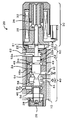
- FIG. 2 is a configuration diagram showing an outline of the configuration of an electromagnetic valve 20.
- the hydraulic circuit 130 is configured to perform hydraulic control of a clutch and a brake incorporated in an automatic transmission mounted on a vehicle, and mechanical oil that pumps hydraulic oil through a strainer 132 by power from an engine (not shown).
- a pump 134, a regulator valve 136 that adjusts hydraulic oil pumped from the mechanical oil pump 134 to generate a line pressure PL, and a modulator pressure PMOD that is generated from the line pressure PL via a modulator valve (not shown).
- the solenoid valve 20 includes a solenoid unit 30 that generates a suction force by a magnetic circuit formed by applying a current to the coil 32 and drives a plunger 36 and a shaft 38 that contacts the plunger 36, and the solenoid unit.
- the pressure regulation valve part 40 which is driven by 30 and functions as a pressure regulation valve, and the pump part 60 which is also driven by the solenoid part 30 and functions as an electromagnetic pump are provided.
- the pressure regulating valve unit 40 and the pump unit 60 are a common member, and are a substantially cylindrical sleeve 22 incorporated in the valve body 10 and having one end attached to the solenoid unit 30, and an end inserted into the internal space of the sleeve 22.
- the spool 24 abutted on the tip of the shaft 38 of the solenoid unit 30, the end plate 26 screwed to the other end of the sleeve 22, and the spool 24 provided between the end plate 26 and the other end of the spool 24.
- a spring 28 that urges the solenoid member 30 toward the solenoid unit 30 side.
- the sleeve 22 includes an input port 42 for inputting hydraulic oil, an output port 44 for outputting the input hydraulic oil, and a drain port for draining the input hydraulic oil, as openings in a region where the pressure regulating valve portion 40 is formed. 46 and a feedback port 48 that inputs the hydraulic oil output from the output port 44 via an oil passage 48 a formed by the inner surface of the valve body 10 and the outer surface of the sleeve 22 and applies a feedback force to the spool 24. Is formed.
- the sleeve 22 has a pump chamber port 62 through which hydraulic oil can flow in and out as an opening in a region where the pump portion 60 is formed.
- the spool 24 is formed as a shaft-like member inserted into the sleeve 22, and is a shaft 51 that is slidable on an inner wall 22 a of the sleeve 22 that is formed at one end and has an inner diameter slightly larger than the outer diameter.
- a cylindrical land 54 that can slide on the inner wall of the sleeve 22, a hollow cylindrical land 56 that functions as a spring receiver for receiving the spring 28 and can slide on the inner wall of the sleeve 22, and the land 54 and the land 56.
- the outer diameter is smaller than the outer diameter of the lands 54 and 56, and the outer diameter increases toward the center from each of the lands 54 and 56.
- a connecting portion 58 that is tapered so as to be able to communicate with each other of the input port 42, the output port 44, and the drain port 46, and the land 54 and the land 52 having a smaller outer diameter are connected to each other. And a connecting portion 59.
- a pressure regulating chamber 45 is formed by the communication portion 58, the lands 54, 56 and the inner wall of the sleeve 22, and a feedback chamber 49 is formed by the communication portion 59, the lands 52, 54 and the inner wall of the sleeve 22,
- a pump chamber 65 is formed adjacent to the feedback chamber 49 by the end face 52 a of the land 52 and the inner walls 22 a and 22 b of the sleeve 22.
- the pump chamber 65 is partitioned from the feedback chamber 49 by the inner wall 22 b of the sleeve 22 and the land 52.
- the shaft 51 and the land 52 are stepped with a diameter difference.
- the land 52 moves to the pump chamber 65 side by the movement of the spool 24, the area of the end surface 52a of the land 52 is increased.
- the volume of the pump chamber 65 increases and the volume of the pump chamber 65 increases by the amount of movement and the negative pressure. Occurs.
- the land 52 is slidably inserted into the inner wall 22b, and there is a slight gap between the land 52 and the inner wall 22b. The feedback chamber 49 leaks into the pump chamber 65 through the gap.
- the operation of the electromagnetic valve 20 of the embodiment thus configured particularly the operation when functioning as a pressure regulating valve will be described.
- the spool 24 is moved to the solenoid part 30 side by the biasing force of the spring 28, so that the input port 42 and the output port 44 are connected via the communication part 58.
- the drain port 46 is blocked by the land 56. Therefore, the maximum hydraulic pressure is output.
- the plunger 36 is attracted by a suction force corresponding to the magnitude of the current applied to the coil 32, and the shaft 38 is pushed out accordingly, and the spool 24 is moved to the end plate 26 side. Move to.
- the input port 42, the output port 44, and the drain port 46 are in communication with each other.
- a part of the hydraulic oil input from the input port 42 is output to the output port 44 and the remainder is output to the drain port 46. Is done.
- the hydraulic oil corresponding to the output pressure of the output port 44 is supplied to the feedback chamber 49 via the feedback port 48, the inside of the feedback chamber 49 becomes a high pressure.
- a feedback force corresponding to the output pressure acts on the spool 24 in the direction toward the end plate 26. Therefore, the spool 24 stops at a position where the thrust (suction force) of the plunger 36, the spring force of the spring 28, and the feedback force are just balanced.
- the spool 24 moves to the end plate 26 side most, the input port 42 is blocked by the land 54, and the output port 44 and the drain port 46 are connected via the communication portion 58. It will be in the state of communication. Therefore, no hydraulic pressure is output.
- the input port 42 and the output port 44 are communicated and the drain port 46 is shut off while the energization to the coil 32 is turned off. I know it works. The operation when functioning as an electromagnetic pump will be described later.
- the switching valve 150 has an output port connected to the clutch C1 via a check valve 180 and a signal pressure input port 152a for inputting the line pressure PL as a signal pressure, an input port 152b connected to the output port 44 of the solenoid valve 20.
- FIG. 3 shows an outline of the configuration centering on the electromagnetic valve 20 and the switching valve 150.
- the check valve 160 for suction has a hollow cylindrical main body 162 in which a center hole 162a having a step with a large diameter and a small diameter is formed at the center of the shaft, and a step between the center hole 162a as a spring receiver.
- a spring 166 inserted from the large diameter side, a ball 164 inserted from the large diameter side into the center hole 162a after inserting the spring 166, and a hollow cylindrical ball receiver 168 inserted into the center hole 162a and receiving the ball 164.
- a snap ring 169 for fixing the ball receiver 168 to the main body 162.
- the discharge check valve 170 is integrally formed with the spool 154 and has a main body 172 in which a central hole 172a is formed in a concave shape in the center of the shaft and a through-hole 172b that penetrates the central hole 172a in the radial direction is formed.
- a spring 176 inserted into the center hole 172a with the bottom of the hole 172a as a spring receiver, a ball 174 inserted into the center hole 172a after inserting the spring 176, and a hollow cylindrical shape inserted into the center hole 172a and receiving the ball 174
- the ball receiver 178 and a snap ring 179 for fixing the ball receiver 178 to the main body 172 are configured.
- the main body 172 of the discharge check valve 170 is formed with a reduced diameter portion 172c in which a part of the outer diameter is reduced.
- the solenoid valve device of the embodiment corresponds to the solenoid valve 20, and the switching valve 150 in which the suction check valve 160 and the discharge check valve 170 are built.
- the electromagnetic valve 20 functions as a pressure regulating valve.
- the switching valve 150 moves the spool 154 downward in the drawing along with the contraction of the spring 156 by the line pressure PL.
- the input port 152b and the output port 152d communicate with each other, and the input port 152f and the drain port 152j communicate with each other via the reduced diameter portion 172c.
- the hydraulic pressure from the output port 44 can be applied to the clutch C1 by causing the electromagnetic valve 20 to function as a pressure regulating valve.
- the hydraulic oil remaining in the pump chamber 65 and the oil passage connected thereto is drained through the input port 152f, the reduced diameter portion 172c, and the drain port 152j in this order.
- the main body 162 of the suction check valve 160 is formed with a communication hole 162b in a portion that comes into contact with the main body 172 of the discharge check valve 170, and the suction check valve 160 and the discharge check valve 170 are discharged.
- the hydraulic oil remaining in the space between is also drained through the output port 152g, the input port 152f, the reduced diameter portion 172c, and the drain port 152j in this order.
- the switching valve 150 causes the spool 154 to move upward in the drawing along with the extension of the spring 156 by the biasing force.
- the communication between the input port 152b and the output port 152d is cut off, the input port 152h and the output port 152g are connected via the suction check valve 160 (center hole 162a), and the input port 152f and the output port 152e are discharged.
- the communication between the input port 152f and the drain ports 152i, 152j is blocked through the check valve 170 (center hole 172a, through hole 172b).
- the solenoid valve 20 when the solenoid unit 30 is released from the state where the spool 22 is pressed against the solenoid unit 30 by the spring 28 and the solenoid 22 is driven, the spool 22 is pushed out. When negative pressure is generated, the suction check valve 160 is opened and the discharge check valve 170 is closed. The hydraulic oil flows through the input port 152h, the suction check valve 160, and the output port 152g of the switching valve 150. They are introduced into the pump chamber 65 in order.
- the hydraulic oil in the pump chamber 65 or the oil passage connected to the pump chamber 65 is drained into the atmosphere.
- the hydraulic oil cannot be sufficiently pressurized, and the pump performance may deteriorate.
- the pump chamber 65 is formed adjacent to the feedback chamber 49, so that hydraulic oil leaks from the feedback chamber 49 that has become high pressure when functioning as a pressure regulating valve to the pump chamber 65. Occurs.
- a flow of hydraulic oil from the pump chamber 65 toward the drain is generated, so that the hydraulic oil can be drained smoothly and air can be prevented from entering.
- the performance of the pump can be quickly exhibited. This is the reason why the pump chamber 65 is formed adjacent to the feedback chamber 49.
- the hydraulic circuit 130 including the electromagnetic valve device of the present invention is applied to a hydraulic circuit of an automatic transmission mounted on a vehicle.
- the vehicle is automatically stopped when the vehicle speed is 0 and an automatic stop condition such as brake on is satisfied, and the engine is automatically stopped when an automatic start condition such as brake off is satisfied.
- the clutch C1 forms a gear ratio for starting (for low-speed running) by being engaged, and during automatic stop so that the vehicle can start quickly when the automatically stopped engine is automatically started. Hydraulic pressure shall be applied.
- the mechanical oil pump 34 is driven by the power from the engine and the line pressure PL is input to the signal pressure input port 152a of the switching valve 150.
- the switching valve 150 communicates the output port 44 of the pressure regulating chamber 45 of the solenoid valve 20 and the clutch C1, and communicates the pump chamber 65 of the solenoid valve 20 and the drain port 152j.
- the solenoid valve 20 functions as a pressure regulating valve for supplying hydraulic pressure to the clutch C1
- the hydraulic oil in the pump chamber 65 is smoothly drained due to leakage of hydraulic oil from the feedback chamber 49 to the pump chamber 65. At the same time, air is prevented from entering.
- the mechanical oil pump 34 is also stopped as the engine is stopped. For this reason, the line pressure PL is released, and the switching valve 150 cuts off the communication between the output port 44 of the pressure regulating chamber 45 and the clutch C1, and connects the suction oil passage 141 and the pump chamber 65 to the suction check valve 160.
- the pump chamber 65 and the clutch C1 are communicated with each other via a discharge check valve 170. Further, in order to apply hydraulic pressure to the clutch C1 during the automatic stop, the state where the electromagnetic valve 20 is functioning as a pressure regulating valve is switched from the state where the electromagnetic valve 20 is functioning as a pressure regulating valve with the automatic engine stop.
- the electromagnetic valve 20 functions as a pressure regulating valve before the automatic stop, and the hydraulic oil from the feedback chamber 49 leaks into the pump chamber 65, and the pump chamber 65 or the oil passage connected to the pump chamber 65 Since the intrusion of air is prevented, the pump performance can be quickly exhibited when the drive as the pump function is started. Therefore, when the engine is automatically stopped, the hydraulic pressure can be smoothly applied to the clutch C1.
- the solenoid valve 20 includes the pressure regulating portion 40 that functions as a pressure regulating valve and the pump portion 60 that functions as an electromagnetic pump, and the sleeve 22 and the spool that slides in the sleeve 22.
- the pump chamber 65 of the pump section 60 is formed adjacent to the feedback chamber 49 of the pressure regulating section 40, and the switching valve 150 communicates between the pump chamber port 62 of the pump chamber 65 and the drain port 152j during pressure regulation. Therefore, it is possible to smoothly drain the hydraulic oil from the pump chamber 65 using the leakage of the hydraulic oil from the feedback chamber 49 to the pump chamber 65, which becomes a high pressure during pressure regulation, and to prevent air from entering the pump chamber 65. it can.
- the performance of the pump can be quickly exhibited. Further, it is possible to prevent the hydraulic oil remaining in the pump chamber 65 from adversely affecting the pressure adjustment accuracy. As a result, it is possible to reduce the size of the entire apparatus by integrating the pump function and the pressure regulating function into the electromagnetic valve 20 in a form that can sufficiently exhibit each function.
- the solenoid valve 20 is integrated as a so-called normal open type linear solenoid, but the pump function is integrated.
- the solenoid valve 200 of the modified example of FIG. It is good also as what integrates a pump function as a linear solenoid.
- the electromagnetic valve 200 of the modified example includes a pressure regulating valve unit 240 that functions as a pressure regulating valve, and a pump unit 260 that functions as an electromagnetic pump.
- the solenoid unit 30 has the same configuration as the solenoid valve 20.
- an input port 242 In the sleeve 222, an input port 242, an output port 244, a drain port 246, and a feedback port 248 are formed in the region of the pressure regulating valve portion 240, and a pump chamber port 262 is formed in the region of the pump portion 260.
- the output port 244 is connected to the input port 152b of the switching valve 150 and the pump chamber port 262 is connected to the input port 152f and the output port 152g of the switching valve 150, as in the solenoid valve 20 of the embodiment. And connected to.
- the spool 224 forms a feedback chamber 249 with the communication portion 259, the lands 254, 256 and the inner wall of the sleeve 222, and the pump chamber 265 is adjacent to the feedback chamber 249 with the land 256, the inner wall of the sleeve 222 and the end plate 226.
- the plunger 36 When energization of the coil 32 is turned on, the plunger 36 is attracted with a suction force corresponding to the applied current, and the spool 24 moves to the end plate 26 side.
- the input port 242, the output port 244 and the drain port 246 are in communication with each other, and a part of the hydraulic fluid input from the input port 242 is output to the output port 244 and the remainder is output to the drain port 246. Is done.
- the feedback chamber 249 is supplied with hydraulic oil corresponding to the output pressure of the output port 244 and becomes high pressure.
- the pump chamber 265 is formed adjacent to the feedback chamber 249.
- the pump when the electromagnetic valve 200 is functioning as a pressure regulating valve, the pump is fed from the feedback chamber 249 that has become a high pressure. Hydraulic oil leaks into the chamber 265. For this reason, the same effect as the embodiment can be obtained.
- the spool 222 In the pump portion 260, when the solenoid portion 30 is driven, the spool 222 is pushed out and positive pressure is generated in the pump chamber 265, thereby discharging the hydraulic oil in the pump chamber 265, and when the solenoid portion 30 is released, the spring is released. The spool 222 is pushed back by 228 and negative pressure is generated in the pump chamber 265, whereby hydraulic oil can be sucked into the pump chamber 265.
- the spool 24 of the electromagnetic valve 20 is inserted into the sleeve 22. However, it is assumed that the spool 24 is inserted directly into the cylindrical space formed in the valve body 10 without the sleeve 22. Also good.
- the switching check valve 150 includes the suction check valve 160 and the discharge check valve 170.
- the discharge check valve and the suction check valve are provided in the valve body 10 outside the switching valve.
- One or both of the check valve switching may be incorporated.
- the switching valve 150 is configured to switch communication between the output port 44 of the electromagnetic valve 20 and the clutch C1, and the like.
- the switching valve 150 is simply connected to the pump chamber port 62 of the electromagnetic valve 20 and the drain port 152j. You may comprise as what switches between interruption
- the hydraulic pressure is supplied to the same clutch C1 when the electromagnetic valve 20 functions as a pressure regulating valve and when the electromagnetic valve 20 functions as an electromagnetic pump.
- the hydraulic pressure may be supplied to different clutches.
- the switching valve 150 is driven using the line pressure PL.
- the switching valve 150 may be driven using a modulator pressure PMOD obtained by reducing the line pressure PL via a modulator valve (not shown).
- the line pressure PL and the modulator pressure PMOD may be driven so as to be supplied to the switching valve 150 via the solenoid valve.
- the solenoid valve device of the embodiment it is used for hydraulic control of a clutch incorporated in an automatic transmission, but is not limited to this, and is used for fluid pressure control of any operating mechanism operated by fluid pressure. It is good.
- the spool 24 inserted into the sleeve 22 corresponds to a “spool”
- the solenoid portion 30 corresponds to an “electromagnetic portion”
- the pump chamber 65 corresponds to a “pump chamber”
- the electromagnetic valve 20 corresponds to “electromagnetic”.
- the switching valve 50 corresponds to a “switching device”.
- the shaft 51 corresponds to the “first sliding portion”
- the land 52 corresponds to the “second sliding portion”
- the inner wall 22a corresponds to the “first inner wall”
- the inner wall 22b corresponds to the “first sliding portion”. 2
- the suction check valve 160 is equivalent to the“ suction check valve ”
- the discharge check valve 170 is equivalent to the“ discharge check valve ”
- the pump chamber port 62 is Corresponds to “in / out port”.
- the present invention can be used in the electromagnetic valve manufacturing industry.
Abstract
Description
円筒状の中空部内に摺動可能に挿入される軸状部材であって流体圧源から供給される流体圧を調圧して出力する調圧室と該調圧された出力圧を導入するフィードバック室とを区画して形成するスプールと、該スプールを電磁力により駆動する電磁部とを有し、前記電磁部からの電磁力の発生とその解除とにより作動流体を吸入して吐出する電磁ポンプとして機能するよう前記中空部と前記スプールとにより前記フィードバック室に隣接して区画されたポンプ室が形成されてなる電磁弁と、
前記電磁弁が調圧バルブとして機能するときには前記ポンプ室内の作動流体を排出する第1の状態とし、前記電磁弁が前記電磁ポンプとして機能するときには該ポンプ室内の作動流体の排出を禁止する第2の状態に切り替える切替装置と
を備えることを要旨とする。
Claims (7)
- 円筒状の中空部内に摺動可能に挿入される軸状部材であって流体圧源から供給される流体圧を調圧して出力する調圧室と該調圧された出力圧を導入するフィードバック室とを区画して形成するスプールと、該スプールを電磁力により駆動する電磁部とを有し、前記電磁部からの電磁力の発生とその解除とにより作動流体を吸入して吐出する電磁ポンプとして機能するよう前記中空部と前記スプールとにより前記フィードバック室に隣接して区画されたポンプ室が形成されてなる電磁弁と、
前記電磁弁が調圧バルブとして機能するときには前記ポンプ室内の作動流体を排出する第1の状態とし、前記電磁弁が前記電磁ポンプとして機能するときには該ポンプ室内の作動流体の排出を禁止する第2の状態に切り替える切替装置と
を備える電磁弁装置。 - 請求項1記載の電磁弁装置であって、
前記スプールは、端部に形成された第1の摺動部と該第1の摺動部よりも大きな外径に形成された第2の摺動部とにより一端が段付き軸状に形成され、
前記ポンプ室は、前記第1の摺動部と摺動可能な内径をもって前記中空部内に形成された第1の内壁と、前記第2の摺動部と摺動可能な内径をもって前記中空部内に形成された第2の内壁と、前記第2の内壁に挿入される前記第2の摺動部の端面とにより囲まれた空間として形成されると共に前記第2の内壁と前記第2の摺動部とにより前記フィードバック室と区画されてなる
電磁弁装置。 - 前記ポンプ室は、前記電磁部からの電磁力の発生とその解除とによる前記スプールの往復動に伴って室内の容積が変化し、該容積の変化に伴って前記室内が負圧となったときに作動流体を吸入し該室内が正圧となったときに該吸入した作動流体を吐出する請求項2記載の電磁弁装置。
- 請求項3記載の電磁弁装置であって、
流体貯留部から前記ポンプ室への作動流体の流れを許容する吸入用逆止弁と、
前記ポンプ室から作動対象への作動流体の流れを許容する吐出用逆止弁とを備え、
前記ポンプ室は、前記吸入用逆止弁と前記吐出用逆止弁とに流路を介して接続された一つの流入出ポートが形成されてなる
電磁弁装置。 - 前記吐出用逆止弁は、前記切替装置に内蔵されてなる請求項4記載の電磁弁装置。
- 前記吸入用逆止弁は、前記切替装置に内蔵されてなる請求項5記載の電磁弁装置。
- 前記切替装置は、前記流体圧源からの流体圧が信号圧として入力され、該信号圧が入力されるときには前記第1の状態に切り替え、該信号圧が入力されないときには前記第2の状態に切り替える切替バルブである請求項1ないし6いずれか1項に記載の電磁弁装置。
Priority Applications (2)
| Application Number | Priority Date | Filing Date | Title |
|---|---|---|---|
| DE201011000449 DE112010000449T5 (de) | 2009-06-11 | 2010-05-14 | Solendoidventilvorrichtung |
| CN2010800099337A CN102341631B (zh) | 2009-06-11 | 2010-05-14 | 电磁阀装置 |
Applications Claiming Priority (2)
| Application Number | Priority Date | Filing Date | Title |
|---|---|---|---|
| JP2009-140122 | 2009-06-11 | ||
| JP2009140122A JP5233852B2 (ja) | 2009-06-11 | 2009-06-11 | 電磁弁装置 |
Publications (1)
| Publication Number | Publication Date |
|---|---|
| WO2010143496A1 true WO2010143496A1 (ja) | 2010-12-16 |
Family
ID=43305354
Family Applications (1)
| Application Number | Title | Priority Date | Filing Date |
|---|---|---|---|
| PCT/JP2010/058158 WO2010143496A1 (ja) | 2009-06-11 | 2010-05-14 | 電磁弁装置 |
Country Status (5)
| Country | Link |
|---|---|
| US (1) | US8347918B2 (ja) |
| JP (1) | JP5233852B2 (ja) |
| CN (1) | CN102341631B (ja) |
| DE (1) | DE112010000449T5 (ja) |
| WO (1) | WO2010143496A1 (ja) |
Families Citing this family (20)
| Publication number | Priority date | Publication date | Assignee | Title |
|---|---|---|---|---|
| US8960226B2 (en) * | 2011-01-12 | 2015-02-24 | Gm Global Technology Operations, Llc | Transmission hydraulic control system having fluid bypass sleeve |
| JP6023093B2 (ja) * | 2011-02-28 | 2016-11-09 | ボーグワーナー インコーポレーテッド | 2段可変力ソレノイド |
| JP5655771B2 (ja) * | 2011-09-15 | 2015-01-21 | 株式会社デンソー | 電磁アクチュエータ |
| KR101339229B1 (ko) * | 2011-11-29 | 2013-12-09 | 현대자동차 주식회사 | 전동식 오일펌프 제어 시스템 |
| JP5693507B2 (ja) * | 2012-03-28 | 2015-04-01 | ジヤトコ株式会社 | 自動変速機の油圧制御装置 |
| CN102620041A (zh) * | 2012-04-23 | 2012-08-01 | 沈阳东北电力调节技术有限公司 | 太阳能小功率供电驱动大型阀门的电液系统 |
| US9175789B2 (en) * | 2012-10-23 | 2015-11-03 | Hamilton Sundstrand Corporation | Pressure regulating valve |
| CN102991746B (zh) * | 2012-12-05 | 2014-09-17 | 成都海科机械设备制造有限公司 | 一种真空管路系统 |
| KR101550600B1 (ko) * | 2013-07-10 | 2015-09-07 | 현대자동차 주식회사 | 자동변속기의 유압회로 |
| US9777830B2 (en) * | 2013-09-25 | 2017-10-03 | Aisin Aw Co., Ltd. | Power transmission device |
| US9627121B2 (en) * | 2014-05-28 | 2017-04-18 | Flextronics Automotive, Inc. | Solenoid robust against misalignment of pole piece and flux sleeve |
| JP2017115962A (ja) * | 2015-12-24 | 2017-06-29 | 株式会社デンソー | 電磁スプール弁 |
| EP3261102A1 (en) | 2016-06-23 | 2017-12-27 | Rain Bird Corporation | Universal solenoid |
| CN110537046A (zh) * | 2017-05-19 | 2019-12-03 | 爱信艾达株式会社 | 安全阀 |
| US10980120B2 (en) | 2017-06-15 | 2021-04-13 | Rain Bird Corporation | Compact printed circuit board |
| EP3467295B1 (en) | 2017-10-03 | 2021-09-08 | Rotex Automation Limited | A solenoid operated unit for detecting and removing undesired fluid with diagnostic metering |
| US11503782B2 (en) | 2018-04-11 | 2022-11-22 | Rain Bird Corporation | Smart drip irrigation emitter |
| CN110206892B (zh) * | 2019-07-05 | 2023-12-26 | 郑州恒达智控科技股份有限公司 | 压力平衡式双控喷水阀 |
| CN112984359B (zh) * | 2019-12-13 | 2022-09-13 | 宝武装备智能科技有限公司 | 一种干油双线分配器主管切换阀 |
| US11721465B2 (en) | 2020-04-24 | 2023-08-08 | Rain Bird Corporation | Solenoid apparatus and methods of assembly |
Citations (5)
| Publication number | Priority date | Publication date | Assignee | Title |
|---|---|---|---|---|
| JP2004176895A (ja) * | 2002-09-30 | 2004-06-24 | Toyoda Mach Works Ltd | 電磁弁 |
| JP2007126974A (ja) * | 2005-11-01 | 2007-05-24 | Nachi Fujikoshi Corp | 電磁ポンプ |
| JP2008180303A (ja) * | 2007-01-25 | 2008-08-07 | Nachi Fujikoshi Corp | 車両用自動変速機の油圧制御装置 |
| WO2008155929A1 (ja) * | 2007-06-18 | 2008-12-24 | Aisin Aw Co., Ltd. | 電磁弁 |
| JP2010121768A (ja) * | 2008-11-21 | 2010-06-03 | Toyota Motor Corp | 流体制御弁および流体制御回路 |
Family Cites Families (11)
| Publication number | Priority date | Publication date | Assignee | Title |
|---|---|---|---|---|
| JPH01156379U (ja) * | 1988-04-20 | 1989-10-27 | ||
| JP2836789B2 (ja) * | 1990-11-05 | 1998-12-14 | アイシン・エィ・ダブリュ株式会社 | リニヤソレノイドバルブ装置 |
| JP2001208234A (ja) * | 2000-01-26 | 2001-08-03 | Denso Corp | 電磁弁 |
| JP2002310326A (ja) * | 2001-04-06 | 2002-10-23 | Aisin Aw Co Ltd | ソレノイドバルブ |
| JP2003120842A (ja) * | 2001-10-16 | 2003-04-23 | Aisin Aw Co Ltd | ソレノイド駆動装置及びそれを用いたリニアソレノイドバルブ |
| JP2005085793A (ja) | 2003-09-04 | 2005-03-31 | Aisin Aw Co Ltd | ソレノイド駆動装置及びソレノイドバルブ |
| JP4524568B2 (ja) * | 2004-03-09 | 2010-08-18 | アイシン・エィ・ダブリュ株式会社 | 自動変速機の油圧制御装置 |
| JP4613576B2 (ja) * | 2004-10-14 | 2011-01-19 | 株式会社ジェイテクト | 電磁弁 |
| JP4981663B2 (ja) | 2005-04-27 | 2012-07-25 | イーグル工業株式会社 | 切替弁 |
| JP4569371B2 (ja) * | 2005-04-28 | 2010-10-27 | 株式会社デンソー | リニアソレノイド |
| JP4919084B2 (ja) | 2007-12-05 | 2012-04-18 | 横河電機株式会社 | シーケンス制御回路 |
-
2009
- 2009-06-11 JP JP2009140122A patent/JP5233852B2/ja not_active Expired - Fee Related
-
2010
- 2010-04-29 US US12/662,715 patent/US8347918B2/en not_active Expired - Fee Related
- 2010-05-14 CN CN2010800099337A patent/CN102341631B/zh not_active Expired - Fee Related
- 2010-05-14 WO PCT/JP2010/058158 patent/WO2010143496A1/ja active Application Filing
- 2010-05-14 DE DE201011000449 patent/DE112010000449T5/de not_active Withdrawn
Patent Citations (5)
| Publication number | Priority date | Publication date | Assignee | Title |
|---|---|---|---|---|
| JP2004176895A (ja) * | 2002-09-30 | 2004-06-24 | Toyoda Mach Works Ltd | 電磁弁 |
| JP2007126974A (ja) * | 2005-11-01 | 2007-05-24 | Nachi Fujikoshi Corp | 電磁ポンプ |
| JP2008180303A (ja) * | 2007-01-25 | 2008-08-07 | Nachi Fujikoshi Corp | 車両用自動変速機の油圧制御装置 |
| WO2008155929A1 (ja) * | 2007-06-18 | 2008-12-24 | Aisin Aw Co., Ltd. | 電磁弁 |
| JP2010121768A (ja) * | 2008-11-21 | 2010-06-03 | Toyota Motor Corp | 流体制御弁および流体制御回路 |
Also Published As
| Publication number | Publication date |
|---|---|
| US20100313980A1 (en) | 2010-12-16 |
| JP2010286047A (ja) | 2010-12-24 |
| CN102341631B (zh) | 2013-07-03 |
| CN102341631A (zh) | 2012-02-01 |
| DE112010000449T5 (de) | 2012-08-30 |
| JP5233852B2 (ja) | 2013-07-10 |
| US8347918B2 (en) | 2013-01-08 |
Similar Documents
| Publication | Publication Date | Title |
|---|---|---|
| JP5233852B2 (ja) | 電磁弁装置 | |
| US8636483B2 (en) | Pump apparatus, power transmission apparatus, and vehicle | |
| US9157544B2 (en) | Solenoid valve | |
| JP6289943B2 (ja) | 可変容量形ポンプ | |
| US8312895B2 (en) | Solenoid valve device | |
| KR101287698B1 (ko) | 동력 전달 장치 및 이를 구비하는 차량 | |
| JP2001280516A (ja) | 調圧弁 | |
| JP5483567B2 (ja) | リリーフ圧力変更機能付きリリーフバルブ | |
| JP2016084847A (ja) | 流体制御装置 | |
| JPWO2009005149A1 (ja) | ソレノイドバルブ | |
| US20230030147A1 (en) | Oil pressure supply device | |
| JP7325192B2 (ja) | 電磁弁及び作業機械 | |
| CN112240380A (zh) | 通气装置 | |
| JP2002267037A (ja) | 電磁弁 | |
| JP5195346B2 (ja) | 動力伝達装置およびこれを搭載する車両 | |
| US20230026991A1 (en) | Oil pressure supply device | |
| JP2019044938A (ja) | 油圧制御装置、ポンプおよび内燃機関への作動油供給システム | |
| JP7309309B2 (ja) | 油圧供給装置 | |
| JP2017009094A (ja) | 流体制御装置 | |
| JP2010121741A (ja) | 動力伝達装置およびこれを搭載する車両 | |
| JP4695004B2 (ja) | トランスミッション付きトルクコンバータのクラッチ油圧制御装置 | |
| JP6476743B2 (ja) | 流体制御装置 | |
| JP2012067890A (ja) | 減圧弁装置 | |
| JP2010084837A (ja) | 流体伝動装置 | |
| JP2010255699A (ja) | 圧力制御装置 |
Legal Events
| Date | Code | Title | Description |
|---|---|---|---|
| WWE | Wipo information: entry into national phase |
Ref document number: 201080009933.7 Country of ref document: CN |
|
| 121 | Ep: the epo has been informed by wipo that ep was designated in this application |
Ref document number: 10786027 Country of ref document: EP Kind code of ref document: A1 |
|
| WWE | Wipo information: entry into national phase |
Ref document number: 1120100004498 Country of ref document: DE Ref document number: 112010000449 Country of ref document: DE |
|
| 122 | Ep: pct application non-entry in european phase |
Ref document number: 10786027 Country of ref document: EP Kind code of ref document: A1 |