WO2010128606A1 - 機器ケースの開閉部分の防水構造 - Google Patents
機器ケースの開閉部分の防水構造 Download PDFInfo
- Publication number
- WO2010128606A1 WO2010128606A1 PCT/JP2010/053825 JP2010053825W WO2010128606A1 WO 2010128606 A1 WO2010128606 A1 WO 2010128606A1 JP 2010053825 W JP2010053825 W JP 2010053825W WO 2010128606 A1 WO2010128606 A1 WO 2010128606A1
- Authority
- WO
- WIPO (PCT)
- Prior art keywords
- opening
- packing
- mounting groove
- cover
- cross
- Prior art date
- Legal status (The legal status is an assumption and is not a legal conclusion. Google has not performed a legal analysis and makes no representation as to the accuracy of the status listed.)
- Ceased
Links
Images











Classifications
-
- B—PERFORMING OPERATIONS; TRANSPORTING
- B65—CONVEYING; PACKING; STORING; HANDLING THIN OR FILAMENTARY MATERIAL
- B65D—CONTAINERS FOR STORAGE OR TRANSPORT OF ARTICLES OR MATERIALS, e.g. BAGS, BARRELS, BOTTLES, BOXES, CANS, CARTONS, CRATES, DRUMS, JARS, TANKS, HOPPERS, FORWARDING CONTAINERS; ACCESSORIES, CLOSURES, OR FITTINGS THEREFOR; PACKAGING ELEMENTS; PACKAGES
- B65D51/00—Closures not otherwise provided for
-
- F—MECHANICAL ENGINEERING; LIGHTING; HEATING; WEAPONS; BLASTING
- F16—ENGINEERING ELEMENTS AND UNITS; GENERAL MEASURES FOR PRODUCING AND MAINTAINING EFFECTIVE FUNCTIONING OF MACHINES OR INSTALLATIONS; THERMAL INSULATION IN GENERAL
- F16J—PISTONS; CYLINDERS; SEALINGS
- F16J15/00—Sealings
- F16J15/02—Sealings between relatively-stationary surfaces
- F16J15/06—Sealings between relatively-stationary surfaces with solid packing compressed between sealing surfaces
-
- B—PERFORMING OPERATIONS; TRANSPORTING
- B65—CONVEYING; PACKING; STORING; HANDLING THIN OR FILAMENTARY MATERIAL
- B65D—CONTAINERS FOR STORAGE OR TRANSPORT OF ARTICLES OR MATERIALS, e.g. BAGS, BARRELS, BOTTLES, BOXES, CANS, CARTONS, CRATES, DRUMS, JARS, TANKS, HOPPERS, FORWARDING CONTAINERS; ACCESSORIES, CLOSURES, OR FITTINGS THEREFOR; PACKAGING ELEMENTS; PACKAGES
- B65D53/00—Sealing or packing elements; Sealings formed by liquid or plastics material
- B65D53/02—Collars or rings
-
- F—MECHANICAL ENGINEERING; LIGHTING; HEATING; WEAPONS; BLASTING
- F16—ENGINEERING ELEMENTS AND UNITS; GENERAL MEASURES FOR PRODUCING AND MAINTAINING EFFECTIVE FUNCTIONING OF MACHINES OR INSTALLATIONS; THERMAL INSULATION IN GENERAL
- F16J—PISTONS; CYLINDERS; SEALINGS
- F16J15/00—Sealings
- F16J15/02—Sealings between relatively-stationary surfaces
-
- F—MECHANICAL ENGINEERING; LIGHTING; HEATING; WEAPONS; BLASTING
- F16—ENGINEERING ELEMENTS AND UNITS; GENERAL MEASURES FOR PRODUCING AND MAINTAINING EFFECTIVE FUNCTIONING OF MACHINES OR INSTALLATIONS; THERMAL INSULATION IN GENERAL
- F16J—PISTONS; CYLINDERS; SEALINGS
- F16J15/00—Sealings
- F16J15/02—Sealings between relatively-stationary surfaces
- F16J15/06—Sealings between relatively-stationary surfaces with solid packing compressed between sealing surfaces
- F16J15/061—Sealings between relatively-stationary surfaces with solid packing compressed between sealing surfaces with positioning means
-
- F—MECHANICAL ENGINEERING; LIGHTING; HEATING; WEAPONS; BLASTING
- F16—ENGINEERING ELEMENTS AND UNITS; GENERAL MEASURES FOR PRODUCING AND MAINTAINING EFFECTIVE FUNCTIONING OF MACHINES OR INSTALLATIONS; THERMAL INSULATION IN GENERAL
- F16J—PISTONS; CYLINDERS; SEALINGS
- F16J15/00—Sealings
- F16J15/02—Sealings between relatively-stationary surfaces
- F16J15/06—Sealings between relatively-stationary surfaces with solid packing compressed between sealing surfaces
- F16J15/062—Sealings between relatively-stationary surfaces with solid packing compressed between sealing surfaces characterised by the geometry of the seat
-
- F—MECHANICAL ENGINEERING; LIGHTING; HEATING; WEAPONS; BLASTING
- F16—ENGINEERING ELEMENTS AND UNITS; GENERAL MEASURES FOR PRODUCING AND MAINTAINING EFFECTIVE FUNCTIONING OF MACHINES OR INSTALLATIONS; THERMAL INSULATION IN GENERAL
- F16J—PISTONS; CYLINDERS; SEALINGS
- F16J15/00—Sealings
- F16J15/02—Sealings between relatively-stationary surfaces
- F16J15/06—Sealings between relatively-stationary surfaces with solid packing compressed between sealing surfaces
- F16J15/10—Sealings between relatively-stationary surfaces with solid packing compressed between sealing surfaces with non-metallic packing
-
- H—ELECTRICITY
- H10—SEMICONDUCTOR DEVICES; ELECTRIC SOLID-STATE DEVICES NOT OTHERWISE PROVIDED FOR
- H10D—INORGANIC ELECTRIC SEMICONDUCTOR DEVICES
- H10D64/00—Electrodes of devices having potential barriers
- H10D64/01—Manufacture or treatment
- H10D64/011—Manufacture or treatment of electrodes ohmically coupled to a semiconductor
-
- B—PERFORMING OPERATIONS; TRANSPORTING
- B65—CONVEYING; PACKING; STORING; HANDLING THIN OR FILAMENTARY MATERIAL
- B65D—CONTAINERS FOR STORAGE OR TRANSPORT OF ARTICLES OR MATERIALS, e.g. BAGS, BARRELS, BOTTLES, BOXES, CANS, CARTONS, CRATES, DRUMS, JARS, TANKS, HOPPERS, FORWARDING CONTAINERS; ACCESSORIES, CLOSURES, OR FITTINGS THEREFOR; PACKAGING ELEMENTS; PACKAGES
- B65D2251/00—Details relating to container closures
- B65D2251/20—Sealing means
- B65D2251/205—Inserted
Definitions
- the present invention relates to a structure for waterproofing an opening / closing part such as a connector cover part or a battery cover part in a case of a device.
- Some small electronic devices such as mobile phones and digital cameras have connector connection parts for data input / output and charging, and battery insertion parts. These connector connection parts and battery insertion parts have been established in equipment cases.
- a cover is detachably fitted into the opening. Such a gap between the case opening and the cover is conventionally sealed by an O-ring to be waterproof.
- FIG. 26 shows such a conventional waterproof structure.
- Reference numeral 100 is a case of a small electronic device
- reference numeral 101 is an opening formed in the case 100
- reference numeral 200 is detachable from the opening 101. It is a cover to be fitted.
- a mounting groove 201 is provided around the outer peripheral surface of the cover 200, and an O-ring 202 is mounted in the mounting groove 201.
- the O-ring 202 is a packing made of a rubber-like elastic material having a circular cross section.
- the cover 200 is fitted into the opening 101 as shown in FIG. 26B from the state where the cover 200 is removed and the opening 101 is opened as shown in FIG.
- the O-ring 202 is twisted due to friction between the inner surface of the opening 101 and the bottom surface of the mounting groove 201, and the sealing performance (waterproofness) by the O-ring 202 may be impaired.
- the O-ring 202 when the O-ring 202 is wound around the mounting groove 201 of the cover 200, the O-ring 202 is likely to be twisted, and there is a possibility that the sealing performance (waterproofness) may be impaired due to mounting failure.
- the present invention has been made in view of the above points, and its technical problem is to prevent deterioration in waterproofing and poor mounting due to twisting of the packing in the mounting groove.
- the waterproof structure according to claim 1 of the present invention has a packing mounted in a mounting groove provided around the outer peripheral surface of the cover, and the cover is attached to the case of the device.
- the packing When the packing is compressed between the inner surface of the opening and the bottom surface of the mounting groove by fitting into the opening, the packing has a flat contact surface with the bottom surface of the mounting groove, The cross-sectional diameter in the width direction is larger than the cross-sectional diameter in the height direction.
- a packing is mounted in a mounting groove provided around the outer peripheral surface of the cover, and the packing is inserted into the opening of the case by fitting the cover into an opening of a device case.
- the packing is compressed between the inner surface of the mounting groove and the bottom surface of the mounting groove, and the cross-sectional shape of the packing is flat with the bottom surface of the mounting groove. It is characterized in that it is flat on the close contact surface, that is, the inner peripheral surface, is an arc-shaped convex surface on the opposite outer peripheral surface, and is formed in a D-shaped cross section as a whole.
- a packing is mounted in a mounting groove provided around the outer peripheral surface of the cover, and the packing is inserted into the opening of the case of the device by inserting the cover into the opening of the device.
- a fitting groove extending in an extending direction of the mounting groove is formed on the bottom surface of the mounting groove, and the packing is fitted with the fitting groove.
- a mating projection that can be mated is formed.
- the waterproof structure according to claim 4 of the present invention is the waterproof structure of the opening and closing part of the device case according to claim 3, wherein the mounting groove has a flat cross-sectional shape on its bottom surface,
- the packing has a cross-sectional shape that is flat on the inner surface of the mounting groove, that is, a flat surface on the inner peripheral surface, an arc-shaped convex surface on the outer peripheral surface on the opposite side, and is formed in a D-shaped cross section as a whole,
- the fitting protrusion is formed on the inner peripheral surface of the packing formed in a D-shaped cross section.
- the waterproof structure according to claim 5 of the present invention is the waterproof structure of the opening and closing part of the device case according to claim 3, wherein the mounting groove has a flat cross-sectional shape at the bottom, and
- the packing has a fitting protrusion on the inner peripheral side that fits in the fitting groove, a sealing protrusion on the outer peripheral side that is in close contact with the inner surface of the opening, and a sealing protrusion on both sides in the width direction. It is characterized by being formed.
- a packing is mounted in a mounting groove provided around the outer peripheral surface of the cover, and the packing is inserted into the opening of the case by fitting the cover into an opening of a case of the device.
- the packing is compressed between the inner surface of the mounting groove and the bottom surface of the mounting groove, and the packing has a flat contact surface with the bottom surface of the mounting groove, and the close contact surface with the inner surface of the opening is a peak portion. It consists of slopes on both sides.
- a packing is mounted in a mounting groove provided around the outer peripheral surface of the cover, and the packing is inserted into the opening of the case by fitting the cover into the opening of the case of the device.
- the packing is compressed between the inner surface of the mounting groove and the bottom surface of the mounting groove, and the cross-sectional shape of the packing is flat with the bottom surface of the mounting groove.
- the contact surface is flat on the inner peripheral surface, that is, the outer peripheral surface on the opposite side is provided with a ridge and slopes on both sides thereof, and is formed in a pentagonal section as a whole.
- the waterproof structure according to claim 8 of the present invention is the waterproof structure of the opening / closing part of the device case according to claim 6 or 7, wherein the slope on the cover insertion direction side of the slopes on both sides of the ridge portion of the packing is provided.
- the slope is relatively gentle and the slope on the side opposite to the cover insertion direction is relatively steep.
- the waterproof structure according to claim 9 of the present invention is the waterproof structure of the opening and closing part of the device case according to claim 6 or 7, wherein the slope on the cover insertion direction side of the slopes on both sides of the ridge portion of the packing. Is relatively gentle, the slope on the opposite side to the cover insertion direction is relatively steep, and the ridge portion of the packing is unevenly distributed to the opposite side of the cover insertion direction from the central portion in the width direction of the packing. It is characterized by being.
- the packing is flat at the close contact surface with the bottom surface of the mounting groove, and the cross-sectional diameter in the width direction is set larger than the cross-sectional diameter in the height direction. Therefore, compared to conventional O-rings that are easy to roll, the seating on the bottom surface of the mounting groove is stable, and even when subjected to a load in the torsion direction, it is difficult to twist, thus effectively preventing deterioration of waterproofness. it can.
- the cross-sectional shape of the packing is flat on the bottom surface of the groove, that is, the cross-sectional shape of the packing is flat on the contact surface with the bottom surface of the groove, that is, the inner peripheral surface.
- the outer peripheral surface on the opposite side is an arc-shaped convex surface and is formed in a D-shaped cross section as a whole, so that the seating on the bottom surface of the mounting groove is more stable than the conventional O-ring that is easy to roll.
- the fitting protrusion formed on the packing is fitted into the fitting groove formed on the bottom surface of the mounting groove.
- the packing is restrained in the mounting groove, and even if it receives a load in the torsional direction, it becomes difficult to twist, so that it is possible to effectively prevent a decrease in waterproofness.
- the structure of Claim 4 since the inner peripheral surface of packing is flat cross-sectional shape, the seating to the bottom face of a mounting groove is stabilized.
- the seal projection protruding to both sides in the width direction is in close contact with the bottom surface of the mounting groove, so that the seating on the bottom surface of the mounting groove is stabilized. Further, since the axial width of the outer peripheral seal projection closely contacting the inner surface of the opening is set to be smaller than the axial width of the entire packing, the compression reaction force in the mounted state is set to be small.
- the bottom surface of the mounting groove to the bottom surface of the mounting groove is easier than a conventional O-ring that is easy to roll. Sitting is stable, and even when subjected to a load in the torsional direction, it becomes difficult to twist, so that it is possible to effectively prevent a decrease in waterproofness.
- the close contact surface with the inner surface of the opening of the case is composed of a ridge and slopes on both sides thereof, compared to the case where the close contact surface with the inner surface of the opening forms an arcuate convex surface,
- the compression reaction force is reduced, and the press-fit resistance when the cover is fitted into the opening of the case and the wear of the packing can be reduced. Therefore, it is possible to prevent the packing from being twisted and twisting of the packing in the groove due to repeated opening and closing of the cover, etc., and to reduce the press-fit resistance when the cover is fitted into the opening of the case, and to reduce the waterproof performance due to wear. Can be suppressed.
- the cross-sectional shape of the packing is flat on the bottom surface thereof, and the cross-sectional shape of the packing is on the contact surface with the bottom surface of the mounting groove, that is, the inner peripheral surface. Due to the flat shape, the seating on the bottom of the mounting groove is more stable than conventional O-rings that are easy to roll, making it difficult to twist even when subjected to a load in the torsional direction, thus effectively reducing the waterproofness. Can be prevented.
- the cross-sectional shape of the packing is such that the outer peripheral surface on the side opposite to the inner peripheral surface is provided with a ridge and slopes on both sides thereof, and is formed into a pentagonal cross section as a whole, it is in close contact with the inner surface of the opening.
- the crushing allowance setting is the same compared to the surface having an arcuate convex surface, the compression reaction force is reduced, reducing the press-fit resistance when fitting the cover into the case opening and the wear of the packing. Can be reduced.
- the frictional resistance of the packing with the inner surface of the opening of the case is small in the cover insertion direction and large in the opposite direction. Moreover, since the surface pressure of the packing with respect to the inner surface of the opening of the case rises abruptly on the side opposite to the cover insertion direction with respect to the peak portion, the resistance against the water intrusion pressure from the outside increases. Therefore, the cover can be more easily fitted into the opening of the case, and the cover is firmly fitted from the opening of the case so that the cover is not easily dropped, thereby further improving the waterproof performance.
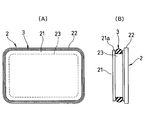
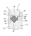
- FIG. 2 shows an example of packing in the first embodiment, where (A) is a front view and (B) is a cross-sectional view taken along line BB of (A). It is sectional drawing which expands and shows a part of packing of FIG. Similarly, in the first embodiment, it is an enlarged cross-sectional view showing a state in which a cover is fitted into an opening of a case.
- FIG. 2 shows a packing in the second embodiment, in which (A) is a front view and (B) is a cross-sectional view along B-B ′ of (A).
- FIG. 2 shows a packing in the second embodiment, in which (A) is a front view and (B) is a cross-sectional view along B-B ′ of (A).
- FIG. 2 shows a packing in the second embodiment, in which (A) is a front view and (B) is a cross-sectional view along B-B ′ of (A).
- it is a perspective view showing a state in which the packing is mounted in the packing mounting groove.
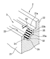
- 5th embodiment of the waterproof structure of the opening-and-closing part of the apparatus case which concerns on this invention it is a cross-sectional perspective view which shows the state by which packing was mounted
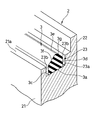
- 6th embodiment of the waterproof structure of the opening-and-closing part of the apparatus case which concerns on this invention it is a cross-sectional perspective view which shows the state by which packing was mounted
- reference numeral 1 is a case of a small electronic device
- reference numeral 2 is a cover that is detachably fitted into an opening 11 provided in the case 1.
- the opening 11 opened in the case 1 has a rectangular shape with rounded corners, that is, the inner peripheral surface thereof has a plane portion and a curved surface portion alternately in the circumferential direction.
- the cover 2 has a plate shape as a whole. As shown in FIG. 5, the cover 2 is formed so as to be inserted from the insertion portion 21 that can be inserted into the opening 11 of the case 1 and the outer end portion of the insertion portion 21. And a flange 22 facing the outer surface 1a of the case 1.
- the outer peripheral surface 21a of the insertion portion 21 of the cover 2 has a projection shape with respect to the insertion direction substantially similar to the opening shape of the opening portion 11 of the case 1, that is, a rectangular shape with rounded corners as shown in FIG. And curved surface portions alternately in the circumferential direction, which is slightly smaller than the opening 11.
- a mounting groove (also simply referred to as “groove” or “packing mounting groove”) 23 is provided around the outer peripheral surface 21 a of the insertion portion 21, and the mounting groove 23 has a substantially U-shaped cross-sectional shape. That is, it comprises a flat bottom surface 23a parallel to the outer peripheral surface 21a of the insertion portion 21 and a pair of inner side surfaces 23b rising at right angles from both sides thereof.
- a packing 3 made of a rubber-like elastic material (rubber material or synthetic resin material having rubber-like elasticity) is attached to the mounting groove 23 described above.
- the packing 3 is formed in an annular shape as shown in FIG. 3A and has a D-shaped cross section as shown in FIG. Specifically, in the cross-sectional shape shown in FIGS. 4 and 5, the inner peripheral surface 3 a that is in close contact with the bottom surface 23 a of the mounting groove 23 is flat, protrudes to the outside of the mounting groove 23, and the inner surface of the opening 11 of the case 1.
- the outer peripheral surface 3b press-contacted in an appropriate deformation state is an arcuate convex surface.
- the inner peripheral surface 3a of the packing 3 corresponds to the close contact surface described in claim 1.
- the cross-sectional diameter L1 of the packing 3 in the width direction is larger than the cross-sectional diameter L2 in the height direction, that is, L2 / L1 ⁇ 1.
- L2 is larger than the depth of the mounting groove 23.
- the cover 2 is press-fitted into the opening 11 of the case 1 via the packing 3, and the packing 3 is attached to the bottom surface 23 a of the mounting groove 23 and the inner peripheral surface of the opening 11.
- the opening 11 is closed in a sealed state to achieve waterproofing.
- the packing 3 has a flat inner peripheral surface 3a in close contact with the bottom surface 23a of the mounting groove 23, and L2 / L1 ⁇ 1, so that a force in the rolling (twisting) direction is applied.
- the packing 3 is not twisted by friction with the inner peripheral surface 11a of the opening 11 and the bottom surface 23a of the mounting groove 23, and excellent sealing performance (waterproofness) by the packing 3 is ensured.
- the packing 3 is formed in an annular shape as shown in FIG. 3, the non-circular cover having a plane portion and a curved surface portion alternately in the circumferential direction as shown in FIG. 1 and FIG.
- the twist is obtained by making the packing 3 have a cross-sectional shape as shown in FIG. Since it becomes difficult, it can prevent effectively that sealing performance (waterproofness) is impaired by mounting
- FIGS. 7 to 10 show a second embodiment of the present invention.
- reference numeral 1 is a case of a small electronic device such as a mobile phone
- reference numeral 2 is a cover that is detachably fitted into the opening 11 opened as a connector insertion portion or the like in the case 1.
- the opening 11 of the case 1 has a square shape with rounded corners, that is, the inner peripheral surface 11a has a plane portion and a curved surface portion alternately in the circumferential direction.
- the cover 2 has a plate-like shape as a whole. The cover 2 is inserted into the opening 11 of the case 1 and is extended from the outer end of the insertion portion 21 so as to face the outer surface 12 of the case 1. And a flange 22 to be provided.
- the outer peripheral surface 21a of the insertion portion 21 of the cover 2 has a projection shape with respect to the insertion direction substantially similar to the opening shape of the opening portion 11 of the case 1, that is, a rectangular shape with rounded corners as shown in FIG. And curved surface portions alternately in the circumferential direction, which is slightly smaller than the opening 11.
- a mounting groove 23 is provided around the outer peripheral surface 21 a of the insertion portion 21 of the cover 2, and the packing 3 is mounted in the mounting groove 23.
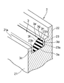
- the mounting groove 23 includes a bottom surface 23a having a flat cross-sectional shape parallel to the outer peripheral surface 21a of the insertion portion 21 of the cover 2 and a pair of inner side surfaces 23b rising substantially vertically from both sides thereof, and is located at an intermediate position in the width direction of the bottom surface 23a. Is formed with a fitting groove 24 having a U-shaped cross section extending in the extending direction of the mounting groove 23.
- the packing 3 is formed in an annular shape as shown in FIG. 9A by a rubber-like elastic material (rubber material or synthetic resin material having rubber-like elasticity).
- the cross section includes a main body 31 having a D-shaped cross section and a fitting protrusion 32 formed on the inner peripheral surface 31 a.
- the main body 31 of the packing 3 is held in the mounting groove 23, and the inner peripheral surface 31 a that is in close contact with the bottom surface 23 a of the mounting groove 23 has a flat cross section, and the outside of the mounting groove 23.
- An outer peripheral surface 31b that protrudes and is pressed into contact with the inner peripheral surface 11a of the opening 11 of the case 1 in an appropriate deformation state forms a convex surface having an arcuate cross section, and a bottom surface 23a of the mounting groove 23 and an inner peripheral surface 11a of the opening 11
- a slight gap is provided with respect to the inner side surface 23b of the mounting groove 23.
- the fitting protrusion 32 is closely fitted in the fitting groove 24 formed on the bottom surface 23 a of the mounting groove 23.
- the cover 2 is press-fit with the insertion portion 21 inserted into the opening 11 of the case 1 via the packing 3.
- the opening 3 is opened.
- the part 11 is closed in a sealed state to achieve waterproofing.
- the packing 3 is constrained by closely fitting the fitting protrusion 32 with the fitting groove 24 formed on the bottom surface 23a of the mounting groove 23, so that the packing 3 has a rolling (twisting) direction shown in FIG.
- the resistance when the force F is applied is large. Therefore, in the process of fitting the cover 2 into the opening portion 11, the packing 3 (main body portion 31) is connected to the inner peripheral surface 11 a of the opening portion 11 and the bottom surface 23 a of the mounting groove 23. It is not twisted by friction, and an excellent sealing property (waterproofness) is ensured.
- the fitting protrusion 32 is inserted into the fitting groove on the bottom surface 23 a of the mounting groove 23 while lightly pressing the main body 31. 24, the fitting protrusion 32 is sequentially fitted into the fitting groove 24, so that the packing 3 (main body portion 31) is not twisted, and the sealing property (waterproofness) due to poor mounting. Can be effectively prevented from being damaged.
- FIGS. 11 to 13 show a third embodiment of the present invention.
- the third embodiment differs from the second embodiment described above in the cross-sectional shapes of the fitting groove 24 and the packing 3.
- the fitting groove 24 formed in the intermediate position in the width direction of the bottom surface 23a of the mounting groove 23 has a substantially U-shaped cross section as shown in FIGS.
- the packing 3 has an inner-side fitting projection 32 having a convex surface having an arcuate cross section corresponding to the fitting groove 24, and an outer-side sealing projection 33 having a sectional shape symmetrical to the fitting projection 32 by 180 degrees.
- the seal protrusions 34 and 35 on both sides in the width direction are 90 degrees symmetrical to the fitting protrusion 32 in a direction different from the fitting protrusion 32 and the seal protrusion 33 by 90 degrees. That is, it has a substantially cross-sectional shape.
- the fitting protrusion 32 of the packing 3 is closely fitted into the fitting groove 24 formed on the bottom surface 23a of the mounting groove 23, and the outer peripheral seal protrusion 33 protrudes to the outside of the mounting groove 23 and It is pressed against the inner peripheral surface 11a of the opening 11 in an appropriate deformed state. Further, the seal protrusions 34 and 35 on both sides in the width direction are held in the mounting groove 23, the tip is in close contact with the inner side surfaces 23 b and 23 b of the mounting groove 23, and the inner peripheral portion is in close contact with the bottom surface 23 a of the mounting groove 23.
- the cover 2 is press-fitted into the opening 11 of the case 1 through the packing 3.
- the packing 3 is sandwiched between the bottom surface 23a and the fitting groove 24 of the mounting groove 23 and the inner peripheral surface 11a of the opening 11 in an appropriately compressed state, whereby the opening 11 is sealed. It closes in a state and aims at waterproofing.
- the fitting protrusion 32 on the inner peripheral side is closely fitted into the fitting groove 24 formed on the bottom surface 23 a of the mounting groove 23, and the tips of the seal protrusions 34 and 35 on both sides in the width direction are mounted. Since the inner surface 23b of the groove 23 is in close contact with the inner surface 23b, the resistance when the force F in the rolling (twisting) direction shown in FIG. 13 is applied is large, and therefore, in the process of fitting the cover 2 into the opening 11, The packing 3 is not twisted by friction with the inner peripheral surface 11a of the opening 11 and the bottom surface 23a of the mounting groove 23, and excellent sealing performance (waterproofness) is ensured.
- the fitting protrusion 32 is fitted into the bottom surface 23a of the mounting groove 23 while lightly pressing the seal protrusions 33 to 35. If the fitting groove 32 is pushed into the fitting groove 24, the fitting protrusion 32 is sequentially fitted into the fitting groove 24, so that the packing 3 (main body portion 31) is not twisted. Property) can be effectively prevented.
- the fitting protrusion 32 is not necessarily continuous in an endless manner with respect to the extending direction of the packing 3, and can be intermittent. In this way, it is not necessary to perform the work of fitting the fitting protrusion 32 into the fitting groove 24 when the packing 3 is attached, and it is possible to prevent air from being trapped in the fitting groove 24.
- FIGS. 14 to 19 show a fourth embodiment of the present invention.
- reference numeral 1 is a case of a small electronic device
- reference numeral 2 is a case. 1 is a cover that is detachably fitted in the opening 11 for battery insertion or connector connection established in FIG.
- the opening 11 opened in the case 1 has a rectangular shape with rounded corners, an oblong shape (not shown), or the like. It has a plane part and a curved surface part alternately in the circumferential direction.
- the cover 2 has a plate shape as a whole.
- the cover 2 is inserted into the opening 11 of the case 1 and is extended from the outer end of the insertion portion 21 so as to face the outer surface 1 a of the case 1. And a flange 22 to be provided.
- the insertion portion 21 of the cover 2 has a projection shape with respect to the insertion direction that is substantially similar to the opening shape of the opening portion 11 of the case 1 and exhibits a square shape with rounded corners as in the example shown in FIG. There is an oval shape as in the example shown in FIG. 17, that is, it has plane portions and curved surface portions alternately in the circumferential direction, and is slightly smaller than the opening 11.
- a mounting groove 23 is provided on the outer peripheral surface 21a of the insertion portion 21.
- the mounting groove 23 has a substantially U-shaped cross-sectional shape. That is, it consists of a flat bottom surface 23a parallel to the outer peripheral surface 21a of the insertion portion 21 and a pair of inner side surfaces 23b rising at right angles from both sides thereof.
- a packing 3 made of a rubber-like elastic material (rubber material or synthetic resin material having rubber-like elasticity) is attached to the mounting groove 23 of the cover 2.
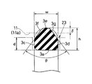
- the packing 3 is formed in an annular shape and has a pentagonal cross section. As shown in FIG. 18, the height h in the radial direction is higher than the depth d of the mounting groove 23, and The inner peripheral surface 3a that is in close contact with the bottom surface is flat, and both side surfaces 3c and 3d that rise from both ends in the width direction have a flat shape perpendicular to the inner peripheral surface 3a, and protrude to the outside of the mounting groove 23.
- An outer peripheral surface that is press-contacted to the inner surface of one opening portion 11 in an appropriate deformation state includes a peak portion 3e and slopes 3f and 3g extending from the peak portion 3e toward both side surfaces 3c and 3d.
- the peak 3e is located in the center of the packing 3 in the width direction, and the slopes 3f and 3g on both sides of the peak 3e are equal to each other.
- the inner peripheral surface 3a corresponds to the “close contact surface with the bottom surface of the mounting groove” recited in claim 6 or 7.
- the packing 3 has a width w of about 1.1 mm and a height h of about 1.0 mm, that is, h / w ⁇ 1.
- the angle ⁇ between the inclined surfaces 3f and 3g is about 74 degrees
- the peak portion 3e is chamfered so as to form an R surface having a curvature radius of about 0.3 mm
- the inner circumferential surface 3a and the side surfaces 3c and 3d Corner portions of the corner portions and the side surfaces 3c, 3d and the inclined surfaces 3f, 3g are also chamfered so as to form an R surface having a curvature radius of about 0.2 mm.
- the cover 2 has its insertion portion 21 press-fitted into the opening 11 of the case 1 via the packing 3, and the packing 3 is connected to the mounting groove 23.
- the opening portion 11 is closed in a hermetically sealed state for waterproofing.
- the packing 3 has a flat inner peripheral surface 3a that is in close contact with the bottom surface 23a of the mounting groove 23, and therefore has a large resistance when a force in the rolling (twisting) direction is applied.
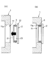
- the frictional resistance with the inner surface 11a of the opening 11 due to force is small. Accordingly, the packing 3 is twisted in the process of fitting the cover 2 into the opening 11 as shown in FIG. 19B from the state in which the opening 11 is opened as shown in FIG. Therefore, excellent sealing performance (waterproofness) by the packing 3 is ensured.
- this since h / w ⁇ 1 in the illustrated embodiment, this also contributes to prevention of twisting of the packing 3.
- the packing 3 has a smaller compression reaction force than the packing 3 having a D-shaped cross section as shown in FIG. 4 described above, that is, the outer peripheral surface 3b is a convex surface having an arcuate cross section.
- the outer peripheral surface is a ridge portion 3e and slopes 3f on both sides thereof, as compared with the packing 3 whose outer peripheral surface forms an arcuate convex surface.
- 3 g of the packing 3 of this embodiment has a small volume at the outer peripheral portion, and therefore, if the crushing allowance ⁇ is the same, the amount of compression is smaller than that of the packing 3 having a D-shaped cross section. For this reason, the frictional resistance of the packing 3 with respect to the inner surface 11a of the opening 11 is reduced, and the press-fitting resistance when the cover 2 is fitted into the opening 11 as shown in FIG. Can be reduced.
- the packing 3 has a flat inner peripheral surface 3a that is in close contact with the bottom surface 23a of the mounting groove 23, so that it is difficult to twist even during the mounting process to the mounting groove 23. It can prevent effectively that (waterproofness) is impaired.
- FIGS. 20 to 23 show a fifth embodiment of the present invention.
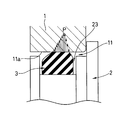
- the difference from the fourth embodiment described above is that, as shown in FIGS. 20 and 21, the peak portion 3e of the packing 3 is more opposite to the cover insertion direction than the center in the width direction. That is, the axial distance L3 between the ridge portion 3e and the side surface 3c on the cover insertion direction side is the same as that between the ridge portion 3e and the side surface 3d on the opposite side to the cover insertion direction.
- the slope ⁇ of the slope 3f on the cover insertion direction side is relatively gentle, and the slope ⁇ of the slope 3g on the opposite side to the cover insertion direction is larger than the axial distance L4.
- Other parts can be basically configured in the same manner as in the fourth embodiment.
- the surface pressure P against the inner surface 11a of the opening 11 of the case 1 is increased as shown in FIG. Since it is distributed so as to rise suddenly on the side opposite to the insertion direction, the resistance against the intrusion pressure of water or the like from the outside increases, and the waterproof performance can be further enhanced.
- L3: L4 is 1: 1 to 5: 1. It is desirable to be in the range.
- FIGS. 24 and 25 show a sixth embodiment of the present invention.
- the peak 3e is located in the center of the packing 3 in the width direction, and the slope ⁇ of the slope 3f on the cover insertion direction side of the slopes 3f and 3g on both sides of the peak 3e is relative.
- the slope ⁇ of the slope 3g opposite to the cover insertion direction is relatively steep, that is, ⁇ ⁇ . Therefore, the bottom 3h of the slope 3g opposite to the cover insertion direction is formed in a concave shape due to the difference between the gradients ⁇ and ⁇ .
- Other parts can be basically configured in the same manner as in the fifth embodiment.
- the twisting of the packing 3 can be effectively prevented, the wear of the packing 3 can be reduced, and ⁇ ⁇ .
- the effect similar to the configuration is obtained, that is, the frictional resistance of the packing 3 against the inner surface 11a of the opening 11 of the case 1 is small in the cover insertion direction, and large in the direction opposite to the cover insertion direction, The surface pressure with respect to the inner surface 11a of the opening 11 of the case is distributed so as to rise suddenly on the opposite side to the cover insertion direction, and the resistance against the intrusion pressure of water or the like from the outside increases.
- the crushing allowance ⁇ and the like are the same as those of the packing 3 shown in FIG. Since the compression amount (compression reaction force) is further reduced as compared with the packing 3 of FIG. 18, the press-fit resistance when the cover 2 is fitted into the opening 11 and the wear of the packing 3 can be further reduced.
Landscapes
- Engineering & Computer Science (AREA)
- General Engineering & Computer Science (AREA)
- Mechanical Engineering (AREA)
- Physics & Mathematics (AREA)
- Geometry (AREA)
- Gasket Seals (AREA)
- Casings For Electric Apparatus (AREA)
- Pressure Vessels And Lids Thereof (AREA)
Abstract
Description
まず図1の斜視図において、参照符号1は小型電子機器のケース、参照符号2はケース1に開設された開口部11に着脱可能に嵌め込まれるカバーである。
次に、図7~図10は、本発明の第二の実施の形態を示すものである。
次に、図11~図13は、本発明の第三の実施の形態を示すものである。この第三の実施の形態において、先に説明した第二の実施の形態と異なるのは、嵌合溝24及びパッキン3の断面形状である。
次に、図20~図23は、本発明の第五の実施の形態を示すものである。
次に、図24及び図25は、本発明の第六の実施の形態を示すものである。
11 開口部
2 カバー
21 挿入部
22 鍔部
23 装着溝
23a 底面
24 嵌合溝
3 パッキン
3a 内周面(密接面)
3b 外周面
3c,3d 側面
3e 峰部
3f,3g 斜面
3h 裾部
31 本体部
32 嵌合突起
33,34,35 シール突起
Claims (9)
- カバーの外周面に周設された装着溝にパッキンが装着され、前記カバーを機器のケースの開口部に嵌め込むことにより前記パッキンが前記開口部の内面と前記装着溝の底面との間で圧縮されるものにおいて、
前記パッキンは、前記装着溝の底面との密接面が平坦状であり、幅方向の断面径を高さ方向の断面径より大きくしたことを特徴とする機器ケースの開閉部分の防水構造。 - カバーの外周面に周設された装着溝にパッキンが装着され、前記カバーを機器のケースの開口部に嵌め込むことにより前記パッキンが前記開口部の内面と前記装着溝の底面との間で圧縮されるものにおいて、
前記装着溝の断面形状がその底面で平坦状であるのに伴って、前記パッキンはその断面形状が前記装着溝の底面との密接面すなわち内周面で平坦状であり、反対側の外周面で円弧状の凸面であり、全体として断面D字形に形成されていることを特徴とする機器ケースの開閉部分の防水構造。 - カバーの外周面に周設された装着溝にパッキンが装着され、前記カバーを機器のケースの開口部に嵌め込むことにより前記パッキンが前記開口部の内面と前記装着溝の底面との間で圧縮されるものにおいて、
前記装着溝の底面に、前記装着溝の延長方向へ延びる嵌合溝が形成され、
前記パッキンに、前記嵌合溝と嵌合可能な嵌合突起が形成されたことを特徴とする機器ケースの開閉部分の防水構造。 - 請求項3記載の機器ケースの開閉部分の防水構造において、
前記装着溝の断面形状がその底面で平坦状であるのに伴って、前記パッキンはその断面形状が前記装着溝の底面との密接面すなわち内周面で平坦状であり、反対側の外周面で円弧状の凸面であり、全体として断面D字形に形成されており、
前記断面D字形に形成されたパッキンの内周面に前記嵌合突起が形成されていることを特徴とする機器ケースの開閉部分の防水構造。 - 請求項3記載の機器ケースの開閉部分の防水構造において、
前記装着溝の断面形状がその底面で平坦状であるのに伴って、前記パッキンは、前記嵌合溝に嵌合する内周側の嵌合突起と、前記開口部の内面に密接する外周側のシール突起と、幅方向両側のシール突起とを有して、断面十字形に形成されていることを特徴とする機器ケースの開閉部分の防水構造。 - カバーの外周面に周設された装着溝にパッキンが装着され、前記カバーを機器のケースの開口部に嵌め込むことにより前記パッキンが前記開口部の内面と前記装着溝の底面との間で圧縮されるものにおいて、
前記パッキンは、前記装着溝の底面との密接面が平坦状であり、前記開口部の内面との密接面が峰部とその両側の斜面とからなることを特徴とする機器ケースの開閉部分の防水構造。 - カバーの外周面に周設された装着溝にパッキンが装着され、前記カバーを機器のケースの開口部に嵌め込むことにより前記パッキンが前記開口部の内面と前記装着溝の底面との間で圧縮されるものにおいて、
前記装着溝の断面形状がその底面で平坦状であるのに伴って、前記パッキンはその断面形状が前記装着溝の底面との密接面すなわち内周面で平坦状であり、反対側の外周面で峰部とその両側の斜面とを備える形状であり、全体として断面五角形に形成されていることを特徴とする機器ケースの開閉部分の防水構造。 - 請求項6または7記載の機器ケースの開閉部分の防水構造において、
パッキンの峰部の両側の斜面のうち、カバー挿入方向側の斜面が相対的に緩勾配、カバー挿入方向と反対側の斜面が相対的に急勾配であることを特徴とする機器ケースの開閉部分の防水構造。 - 請求項6または7記載の機器ケースの開閉部分の防水構造において、
パッキンの峰部の両側の斜面のうち、カバー挿入方向側の斜面が相対的に緩勾配、カバー挿入方向と反対側の斜面が相対的に急勾配であり、
かつ前記パッキンの峰部が、パッキンの幅方向中央部よりもカバー挿入方向と反対側へ偏在していることを特徴とする機器ケースの開閉部分の防水構造。
Priority Applications (5)
| Application Number | Priority Date | Filing Date | Title |
|---|---|---|---|
| JP2011512320A JP5321865B2 (ja) | 2009-05-08 | 2010-03-09 | 機器ケースの開閉部分の防水構造 |
| US13/257,564 US20120043331A1 (en) | 2009-05-08 | 2010-03-09 | Water-proof structure for opening of case of appliance |
| KR1020117021791A KR101682068B1 (ko) | 2009-05-08 | 2010-03-09 | 기기 케이스의 개폐 부분의 방수 구조 |
| CN201090000831.4U CN203115093U (zh) | 2009-05-08 | 2010-03-09 | 设备外壳的开闭部分的防水构造 |
| FI20116224A FI126852B (fi) | 2009-05-08 | 2011-12-02 | Vedenpitävä rakenne laitekotelon aukko-osaan |
Applications Claiming Priority (4)
| Application Number | Priority Date | Filing Date | Title |
|---|---|---|---|
| JP2009113544 | 2009-05-08 | ||
| JP2009-113544 | 2009-05-08 | ||
| JP2009155269 | 2009-06-30 | ||
| JP2009-155269 | 2009-06-30 |
Publications (1)
| Publication Number | Publication Date |
|---|---|
| WO2010128606A1 true WO2010128606A1 (ja) | 2010-11-11 |
Family
ID=43050114
Family Applications (1)
| Application Number | Title | Priority Date | Filing Date |
|---|---|---|---|
| PCT/JP2010/053825 Ceased WO2010128606A1 (ja) | 2009-05-08 | 2010-03-09 | 機器ケースの開閉部分の防水構造 |
Country Status (5)
| Country | Link |
|---|---|
| JP (1) | JP5321865B2 (ja) |
| KR (1) | KR101682068B1 (ja) |
| CN (2) | CN202971892U (ja) |
| FI (1) | FI126852B (ja) |
| WO (1) | WO2010128606A1 (ja) |
Cited By (12)
| Publication number | Priority date | Publication date | Assignee | Title |
|---|---|---|---|---|
| JP2011159487A (ja) * | 2010-02-01 | 2011-08-18 | Nec Casio Mobile Communications Ltd | スライド蓋の防水装置、及び電子機器 |
| CN104039428A (zh) * | 2011-09-02 | 2014-09-10 | 纳米水公司 | 用于膜分离装置的密封板 |
| JP5667677B1 (ja) * | 2013-09-13 | 2015-02-12 | 化成工業株式会社 | 車両用シール材 |
| FR3031174A1 (fr) * | 2014-12-31 | 2016-07-01 | Atlantic Industrie Sas | Joint d'etancheite pour radiateur a fluide caloporteur et radiateur correspondant |
| JP2017211340A (ja) * | 2016-05-27 | 2017-11-30 | 株式会社日立製作所 | 放射線測定装置 |
| CN108336550A (zh) * | 2017-12-30 | 2018-07-27 | 杭州速控软件有限公司 | 接口密封结构 |
| JP2018121631A (ja) * | 2017-02-03 | 2018-08-09 | 株式会社ドヨエンジニアリング | テンションナット離脱防止手段を備えた釣りリール |
| CN111194149A (zh) * | 2018-11-15 | 2020-05-22 | 株式会社电装 | 防水壳体 |
| JP2020183790A (ja) * | 2019-05-08 | 2020-11-12 | 株式会社ショーワ | 密封装置、この密封装置を備えた伝動装置、及びこの伝動装置を備えた車両用ステアリング装置 |
| JP2021027023A (ja) * | 2019-08-08 | 2021-02-22 | 三菱電機株式会社 | 照明器具 |
| JP2023172287A (ja) * | 2022-05-23 | 2023-12-06 | 本多電子株式会社 | 携帯医療機器の防滴構造 |
| WO2023233995A1 (ja) * | 2022-06-03 | 2023-12-07 | 株式会社不二工機 | 排水ポンプ |
Families Citing this family (13)
| Publication number | Priority date | Publication date | Assignee | Title |
|---|---|---|---|---|
| JPH0622183Y2 (ja) | 1989-02-27 | 1994-06-08 | 三菱油化株式会社 | サンプルフィーダ |
| JP6015679B2 (ja) * | 2014-01-14 | 2016-10-26 | 株式会社デンソー | ポンプ、および、これを用いたエバポリークチェックシステム |
| US20170211703A1 (en) * | 2014-05-29 | 2017-07-27 | Nok Corporation | Sealing structure and sealing device |
| CN104015997A (zh) * | 2014-06-19 | 2014-09-03 | 上海英宇塑料制品有限公司 | 气密粉罐改良结构 |
| KR101719465B1 (ko) * | 2016-08-01 | 2017-03-24 | 유양산전 주식회사 | 매립 항공등화의 응력 감소 구조 |
| JP6795358B2 (ja) * | 2016-09-07 | 2020-12-02 | マブチモーター株式会社 | シール構造および減速機付きモータ |
| CN106907538A (zh) * | 2017-04-06 | 2017-06-30 | 珠海格力电器股份有限公司 | 管接头装置及汽车空调器 |
| CN108302202B (zh) * | 2018-03-13 | 2023-09-22 | 山东临工工程机械有限公司 | 一种可调向接头及其密封装置 |
| CN110278678B (zh) * | 2018-03-15 | 2024-04-02 | 深圳市三诺数字科技有限公司 | 一种密封结构 |
| WO2020054664A1 (ja) * | 2018-09-10 | 2020-03-19 | イーグル工業株式会社 | 電磁弁ユニット |
| CN216333673U (zh) * | 2021-11-26 | 2022-04-19 | 宁德时代新能源科技股份有限公司 | 一种存储运输装置 |
| KR102375613B1 (ko) * | 2022-01-21 | 2022-03-18 | (주)캐스트프로 | 테두리 결합력이 강화된 전기차 충전기 덮개 |
| CN114562560A (zh) * | 2022-03-09 | 2022-05-31 | 浙江尔格科技股份有限公司 | 变压器冷却芯体前后水室密封结构 |
Citations (9)
| Publication number | Priority date | Publication date | Assignee | Title |
|---|---|---|---|---|
| JPS5597260U (ja) * | 1978-12-27 | 1980-07-05 | ||
| JPH06213326A (ja) * | 1993-01-21 | 1994-08-02 | Seiko Epson Corp | 小型携帯機器用防水パッキン |
| JPH06241148A (ja) * | 1993-02-12 | 1994-08-30 | Suzuki Motor Corp | シール用リングによるシール構造 |
| JPH0861507A (ja) * | 1994-08-23 | 1996-03-08 | Daihatsu Motor Co Ltd | 管継ぎ手装置 |
| JP2001349438A (ja) * | 2000-06-05 | 2001-12-21 | Nok Corp | 密封装置 |
| JP2005003181A (ja) * | 2003-06-16 | 2005-01-06 | Nok Corp | ガスケット |
| JP2006029367A (ja) * | 2004-07-12 | 2006-02-02 | Hirotaka Engineering:Kk | 油空圧アクチュエータ摺動部のシール構造 |
| JP2006316947A (ja) * | 2005-05-16 | 2006-11-24 | Mitsubishi Cable Ind Ltd | 塗装機用ピストンパッキン |
| JP2008289103A (ja) * | 2007-05-21 | 2008-11-27 | Casio Hitachi Mobile Communications Co Ltd | 携帯電子機器 |
Family Cites Families (1)
| Publication number | Priority date | Publication date | Assignee | Title |
|---|---|---|---|---|
| JP3131797B2 (ja) * | 1992-02-28 | 2001-02-05 | 東レ・ダウコーニング・シリコーン株式会社 | 容器状構造体のシール方法 |
-
2010
- 2010-03-09 WO PCT/JP2010/053825 patent/WO2010128606A1/ja not_active Ceased
- 2010-03-09 KR KR1020117021791A patent/KR101682068B1/ko not_active Expired - Fee Related
- 2010-03-09 CN CN201220591113.XU patent/CN202971892U/zh not_active Expired - Fee Related
- 2010-03-09 JP JP2011512320A patent/JP5321865B2/ja not_active Expired - Fee Related
- 2010-03-09 CN CN201090000831.4U patent/CN203115093U/zh not_active Expired - Fee Related
-
2011
- 2011-12-02 FI FI20116224A patent/FI126852B/fi not_active IP Right Cessation
Patent Citations (9)
| Publication number | Priority date | Publication date | Assignee | Title |
|---|---|---|---|---|
| JPS5597260U (ja) * | 1978-12-27 | 1980-07-05 | ||
| JPH06213326A (ja) * | 1993-01-21 | 1994-08-02 | Seiko Epson Corp | 小型携帯機器用防水パッキン |
| JPH06241148A (ja) * | 1993-02-12 | 1994-08-30 | Suzuki Motor Corp | シール用リングによるシール構造 |
| JPH0861507A (ja) * | 1994-08-23 | 1996-03-08 | Daihatsu Motor Co Ltd | 管継ぎ手装置 |
| JP2001349438A (ja) * | 2000-06-05 | 2001-12-21 | Nok Corp | 密封装置 |
| JP2005003181A (ja) * | 2003-06-16 | 2005-01-06 | Nok Corp | ガスケット |
| JP2006029367A (ja) * | 2004-07-12 | 2006-02-02 | Hirotaka Engineering:Kk | 油空圧アクチュエータ摺動部のシール構造 |
| JP2006316947A (ja) * | 2005-05-16 | 2006-11-24 | Mitsubishi Cable Ind Ltd | 塗装機用ピストンパッキン |
| JP2008289103A (ja) * | 2007-05-21 | 2008-11-27 | Casio Hitachi Mobile Communications Co Ltd | 携帯電子機器 |
Cited By (20)
| Publication number | Priority date | Publication date | Assignee | Title |
|---|---|---|---|---|
| JP2011159487A (ja) * | 2010-02-01 | 2011-08-18 | Nec Casio Mobile Communications Ltd | スライド蓋の防水装置、及び電子機器 |
| KR101921244B1 (ko) * | 2011-09-02 | 2018-11-22 | 엘지 나노에이치투오, 인코포레이티드 | 멤브레인 분리 장치용 시일 플레이트 |
| CN104039428A (zh) * | 2011-09-02 | 2014-09-10 | 纳米水公司 | 用于膜分离装置的密封板 |
| JP2014525348A (ja) * | 2011-09-02 | 2014-09-29 | ナノエイチツーオー・インコーポレーテッド | 膜分離装置用のシールプレート |
| EP2750785A4 (en) * | 2011-09-02 | 2015-11-25 | Nanoh2O Inc | SEALING PLATE FOR A MEMBRANE SEALING DEVICE |
| US9795925B2 (en) | 2011-09-02 | 2017-10-24 | Lg Nanoh20, Inc. | Seal plate for membrane separation device |
| JP5667677B1 (ja) * | 2013-09-13 | 2015-02-12 | 化成工業株式会社 | 車両用シール材 |
| FR3031174A1 (fr) * | 2014-12-31 | 2016-07-01 | Atlantic Industrie Sas | Joint d'etancheite pour radiateur a fluide caloporteur et radiateur correspondant |
| JP2017211340A (ja) * | 2016-05-27 | 2017-11-30 | 株式会社日立製作所 | 放射線測定装置 |
| JP2018121631A (ja) * | 2017-02-03 | 2018-08-09 | 株式会社ドヨエンジニアリング | テンションナット離脱防止手段を備えた釣りリール |
| CN108336550A (zh) * | 2017-12-30 | 2018-07-27 | 杭州速控软件有限公司 | 接口密封结构 |
| CN111194149A (zh) * | 2018-11-15 | 2020-05-22 | 株式会社电装 | 防水壳体 |
| CN111194149B (zh) * | 2018-11-15 | 2022-11-22 | 株式会社电装 | 防水壳体 |
| JP2020183790A (ja) * | 2019-05-08 | 2020-11-12 | 株式会社ショーワ | 密封装置、この密封装置を備えた伝動装置、及びこの伝動装置を備えた車両用ステアリング装置 |
| JP7233297B2 (ja) | 2019-05-08 | 2023-03-06 | 日立Astemo株式会社 | 伝動装置、及びこの伝動装置を備えた車両用ステアリング装置 |
| JP2021027023A (ja) * | 2019-08-08 | 2021-02-22 | 三菱電機株式会社 | 照明器具 |
| JP7336943B2 (ja) | 2019-08-08 | 2023-09-01 | 三菱電機株式会社 | 照明器具 |
| JP2023172287A (ja) * | 2022-05-23 | 2023-12-06 | 本多電子株式会社 | 携帯医療機器の防滴構造 |
| JP7795779B2 (ja) | 2022-05-23 | 2026-01-08 | 本多電子株式会社 | 携帯医療機器の防滴構造 |
| WO2023233995A1 (ja) * | 2022-06-03 | 2023-12-07 | 株式会社不二工機 | 排水ポンプ |
Also Published As
| Publication number | Publication date |
|---|---|
| JPWO2010128606A1 (ja) | 2012-11-01 |
| KR20120022724A (ko) | 2012-03-12 |
| JP5321865B2 (ja) | 2013-10-23 |
| CN203115093U (zh) | 2013-08-07 |
| FI20116224L (fi) | 2011-12-02 |
| CN202971892U (zh) | 2013-06-05 |
| KR101682068B1 (ko) | 2016-12-02 |
| FI126852B (fi) | 2017-06-30 |
Similar Documents
| Publication | Publication Date | Title |
|---|---|---|
| JP5321865B2 (ja) | 機器ケースの開閉部分の防水構造 | |
| US20120043331A1 (en) | Water-proof structure for opening of case of appliance | |
| JP3349132B2 (ja) | 低荷重シール | |
| CN106133413B (zh) | 垫片 | |
| US9269933B2 (en) | Gasket | |
| CN102803799B (zh) | 小型电子设备用防水垫圈 | |
| JP6532242B2 (ja) | シール材 | |
| CN101115941A (zh) | 垫圈及两部件间的密封结构 | |
| JP4598819B2 (ja) | 蟻溝用シール材 | |
| CN104653785A (zh) | 轴封装置 | |
| JP2011256885A (ja) | 固定密封構造 | |
| JP2014040847A (ja) | 防水用パッキン | |
| JP5932940B2 (ja) | ラバーガスケット | |
| JP6180713B2 (ja) | 機器ケースの開閉部分の防水構造 | |
| JP2011106485A (ja) | 変形oリング、およびシール構造 | |
| JP4691271B2 (ja) | ガスケット | |
| JP2010067838A (ja) | 電子機器 | |
| JP2003343727A (ja) | 耐プラズマ性シール | |
| JP2009257459A (ja) | ガスケット | |
| JP6574045B2 (ja) | 油圧機器用シールリング | |
| JPWO2017154651A1 (ja) | ガスケットの装着構造 | |
| JP2020085165A (ja) | ガスケット及び電子装置 | |
| JP2005243762A (ja) | 電子機器の防水型筐体 | |
| KR20100090028A (ko) | 밴드 클램프 | |
| JP7473439B2 (ja) | コネクタ |
Legal Events
| Date | Code | Title | Description |
|---|---|---|---|
| WWE | Wipo information: entry into national phase |
Ref document number: 201090000831.4 Country of ref document: CN |
|
| 121 | Ep: the epo has been informed by wipo that ep was designated in this application |
Ref document number: 10772130 Country of ref document: EP Kind code of ref document: A1 |
|
| WWE | Wipo information: entry into national phase |
Ref document number: 2011512320 Country of ref document: JP |
|
| ENP | Entry into the national phase |
Ref document number: 20117021791 Country of ref document: KR Kind code of ref document: A |
|
| WWE | Wipo information: entry into national phase |
Ref document number: 13257564 Country of ref document: US |
|
| NENP | Non-entry into the national phase |
Ref country code: DE |
|
| WWE | Wipo information: entry into national phase |
Ref document number: 20116224 Country of ref document: FI |
|
| 122 | Ep: pct application non-entry in european phase |
Ref document number: 10772130 Country of ref document: EP Kind code of ref document: A1 |