WO2010098241A1 - 反転装置 - Google Patents
反転装置 Download PDFInfo
- Publication number
- WO2010098241A1 WO2010098241A1 PCT/JP2010/052382 JP2010052382W WO2010098241A1 WO 2010098241 A1 WO2010098241 A1 WO 2010098241A1 JP 2010052382 W JP2010052382 W JP 2010052382W WO 2010098241 A1 WO2010098241 A1 WO 2010098241A1
- Authority
- WO
- WIPO (PCT)
- Prior art keywords
- panel
- reversing
- wheel
- wheel shaft
- tower
- Prior art date
Links
- 230000007306 turnover Effects 0.000 title abstract 2
- 230000001681 protective effect Effects 0.000 claims description 27
- 238000000034 method Methods 0.000 claims description 14
- 230000003287 optical effect Effects 0.000 claims description 4
- 238000005096 rolling process Methods 0.000 claims description 3
- 238000012423 maintenance Methods 0.000 description 9
- 239000000463 material Substances 0.000 description 8
- 239000004677 Nylon Substances 0.000 description 1
- 230000000903 blocking effect Effects 0.000 description 1
- 230000008878 coupling Effects 0.000 description 1
- 238000010168 coupling process Methods 0.000 description 1
- 238000005859 coupling reaction Methods 0.000 description 1
- 230000000694 effects Effects 0.000 description 1
- 238000012986 modification Methods 0.000 description 1
- 230000004048 modification Effects 0.000 description 1
- 229920001778 nylon Polymers 0.000 description 1
Images


Classifications
-
- B—PERFORMING OPERATIONS; TRANSPORTING
- B64—AIRCRAFT; AVIATION; COSMONAUTICS
- B64F—GROUND OR AIRCRAFT-CARRIER-DECK INSTALLATIONS SPECIALLY ADAPTED FOR USE IN CONNECTION WITH AIRCRAFT; DESIGNING, MANUFACTURING, ASSEMBLING, CLEANING, MAINTAINING OR REPAIRING AIRCRAFT, NOT OTHERWISE PROVIDED FOR; HANDLING, TRANSPORTING, TESTING OR INSPECTING AIRCRAFT COMPONENTS, NOT OTHERWISE PROVIDED FOR
- B64F5/00—Designing, manufacturing, assembling, cleaning, maintaining or repairing aircraft, not otherwise provided for; Handling, transporting, testing or inspecting aircraft components, not otherwise provided for
- B64F5/10—Manufacturing or assembling aircraft, e.g. jigs therefor
Definitions
- the present invention relates to a reversing device.
- the upper panel 85 is attached to the upper side of the wing structure 87 with the convex side 85a facing up and the concave side 85b facing down, and the lower panel with the convex side 86a facing down and the concave side 86b facing up.
- 86 is attached to the underside of the wing structure 87.
- the upper panel 85 is inverted so that the convex surface side 85a faces upward, and the lower panel 86 is inverted so that the convex surface side 86a faces downward.
- Japanese Patent No. 3614612 and Japanese Patent Laid-Open No. 4-331106 disclose a conventional reversing device.
- An object of the present invention is to provide an inversion device, an inversion system, and an inversion method that can invert an object to be inverted in two directions.
- a reversing device includes a tower that travels on a base, a lifter that lifts and lowers the tower, an object holding unit that holds an object to be reversed, a wheel traveling base, and the object holding unit.
- a wheel shaft rotatably attached to the vehicle and a wheel shaft lock.
- the wheel shaft includes wheels that roll on the wheel travel base.
- the object holding unit is attached to the lifter via a rotation shaft parallel to the wheel shaft.
- the wheel shaft lock locks the wheel shaft so that the wheel does not roll on the wheel travel base and so that the wheel shaft can rotate with respect to the object holding unit.
- the reversing device further includes a control device.
- the control device lowers the lifter in a state in which the wheel shaft lock does not lock the wheel shaft, and in a state in which the tower is stopped so that the rotating shaft is on the front side in the first direction from the wheel shaft.
- maintenance part is reversed in a 1st inversion direction.
- the control device controls the traveling of the tower and the lifting and lowering of the lifter so that the rotating shaft performs a circular motion around the wheel shaft while the wheel shaft lock locks the wheel shaft.
- the object holding unit is inverted in a second inversion direction opposite to the first inversion direction.
- the control device causes the tower to travel backward in the first direction opposite to the front side in the first direction when the object holding unit is reversed in the second reverse direction.
- the inverting device includes a coupler.
- the wheel travel base includes a fixed portion fixed to the base and a tower follower capable of traveling in parallel with the tower.
- the wheel shaft lock is provided in the tower follower.
- the connector connects the tower follower to the tower.
- the wheel travel base includes a wheel shaft lifter that raises and lowers the wheel shaft.
- the object holding unit includes a frame and a clamp device attached to the frame.
- the wheel axle is rotatably attached to the frame.
- the frame is attached to the lifter via the rotating shaft.
- the clamp device clamps the reversal object.
- the clamp device includes a face plate that contacts the reversal object.
- the face plate is replaceable.
- the clamp device is attached to the frame so that the position can be adjusted.
- the reversing system includes a panel edge supporting device that supports the edge portion of the panel from below, a panel surface supporting device on which the panel is placed, and a reversing device.
- the reversing device includes a tower that travels on a base, a lifter that moves up and down the tower, a panel holding unit that receives the panel from the panel edge support device and the panel surface support device, and holds the panel, and a wheel.
- a traveling base, a wheel shaft rotatably attached to the panel holding portion, and a wheel shaft lock are provided.
- the wheel shaft includes wheels that roll on the wheel travel base.
- the panel holding part is attached to the lifter via a rotation axis parallel to the wheel axis.
- the wheel shaft lock locks the wheel shaft so that the wheel does not roll on the wheel travel base and so that the wheel shaft can rotate with respect to the panel holding portion.
- the panel edge support device includes a panel receiving portion that supports the edge portion, and a feeding device that raises and lowers the panel receiving portion and advances and retracts the panel receiving portion in the traveling direction of the tower.
- the panel receiving portion is attached to the slide support that is lifted and lowered by the feeding device, a block support that moves up and down with respect to the slide, and supports the edge portion.
- the slide body includes a stopper. The block support portion stops descending with respect to the slide body by abutting against the stopper.
- the panel receiving block is attached to the block support portion so as to be movable back and forth in the traveling direction of the tower.
- the said panel receiving part is provided with the 2nd spring which receives the force of the running direction of the said tower which acts on the said panel receiving block.
- the panel receiving portion includes a cut portion.
- the panel edge support device includes a detector that detects that the edge portion is disposed in the cut portion.
- the reversing system further comprises a protective cover attached to the edge portion.
- the edge portion includes a first portion covered by the protective cover and a second portion not covered by the protective cover.
- the detector includes a light emitting unit and a light receiving unit. The light emitting unit and the light receiving unit are arranged such that the second portion blocks an optical path between the light emitting unit and the light receiving unit in a state where the protective cover is in contact with the cut portion.
- the reversing system further comprises a protective cover attached to the edge portion.
- the protective cover contacts the panel edge support device.
- the panel surface support device includes a plurality of panel support portions that support the panel and a plurality of feeding devices that respectively advance and retract the plurality of panel support portions.
- the plurality of feeding devices arrange the plurality of panel support portions on a predetermined curved surface.
- the reversing system further comprises a positioning tool.
- the positioning tool includes a table, a slide guide provided on the table, a slide base that slides along the slide guide, a laser pointer supported by the slide base, and the slide base at a plurality of predetermined positions. And a locking portion that locks to the table.
- An inversion method includes a step of inverting the object holding unit in a first inversion direction, and a step of inverting the object holding unit in a second inversion direction opposite to the first inversion direction. It comprises.
- a wheel shaft is rotatably attached to the object holding unit.
- the object holding unit is attached to a lifter via a rotation shaft parallel to the wheel shaft. The lifter can move up and down the tower.
- the step of reversing the object holding portion in the first reversing direction includes a step of rolling a wheel provided on the wheel shaft on a wheel travel base while lowering the lifter.
- the step of reversing the object holding part in the second reversing direction is to fix the position of the wheel shaft and to move the tower and the lifter so that the rotating shaft performs a circular motion around the wheel shaft.
- Each step includes running and raising / lowering.
- a reversing device capable of reversing a reversal object in two directions.
- FIG. 1 shows the assembly process of the main wing.
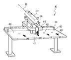
- FIG. 2 is a top view of the inverting device provided in the inverting system according to the first embodiment of the present invention.
- FIG. 3 is a side view of the reversing device.
- FIG. 4 is a side view of the panel holding unit included in the reversing device.
- FIG. 5 is a side view of the panel surface support device and the panel edge support device provided in the reversing system.
- FIG. 6 is a partial cross-sectional view of the main wing panel.
- FIG. 7 shows a detailed structure of a panel receiving portion provided in the panel edge support device.
- FIG. 8 is a perspective view of a positioning tool provided in the reversing system.
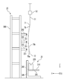
- FIG. 9 shows the step of lowering the main wing panel suspended by the load bar.
- FIG. 10 shows the step of the panel receiving portion engaging the edge of the main wing panel.
- FIG. 11 shows the step of positioning the edge of the main wing panel.
- FIG. 12 shows a step of positioning the panel support portion provided in the panel surface support apparatus.
- FIG. 13 shows the step of placing the main wing panel on the panel support.
- FIG. 14 shows the step of advancing the panel holding part to the main wing panel receiving position.
- FIG. 15 shows the positional relationship between the panel holding portion and the main wing panel at the main wing panel receiving position.
- FIG. 16 shows a step in which the panel holding part clamps the wing panel.
- FIG. 17 shows the step of retracting the panel holder from the main wing panel receiving position.
- FIG. 10 shows the step of the panel receiving portion engaging the edge of the main wing panel.
- FIG. 11 shows the step of positioning the edge of the main wing panel.
- FIG. 12 shows
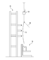
- FIG. 18 shows a step of inverting the panel holding portion in the first inversion direction.
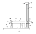
- FIG. 19 shows a step of raising the panel holding part.
- FIG. 20 shows a step of lowering the panel holding portion in order to deliver the main wing panel to an AGV (Automated Guided Vehicle).
- FIG. 21 shows the step in which the AGV receives the wing panel from the panel holder.
- FIG. 22 shows the step of attaching the main wing panel to the underside of the wing structure.
- FIG. 23 shows a step of lowering the panel holding portion in order to replace the face plate.
- FIG. 24 shows a step of inverting the panel holding portion in the second inversion direction opposite to the first inversion direction.
- FIG. 25 shows a step in which the sling jig receives the main wing panel from the panel holding part.
- FIG. 26 shows the step of attaching the main wing panel to the upper side of the wing structure.
- the inversion system includes an inversion device 10.
- the reversing device 10 includes a tower traveling base 100, a wheel traveling base 110, a traveling tower 120, a lifter 121, a panel holding unit 130, a rotating shaft 135, a wheel shaft 137, and a control device 140.
- the X direction, the Y direction, and the Z direction are shown.
- the X direction is a first horizontal direction
- the Y direction is a second horizontal direction perpendicular to the first horizontal direction
- the Z direction is a vertical direction.
- the tower traveling base 100 includes a tower guide 101, a follower guide 102, and a feeding device 105.
- the feeding device 105 drives and positions the traveling tower 120 in the Y direction.
- the feeding device 105 includes, for example, a ball screw.
- the traveling tower 120 travels on the tower traveling base 100 while being guided in the Y direction by the tower guide 101.
- the traveling tower 120 includes a coupler 122.
- the lifter 121 is guided by the traveling tower 120 to raise and lower the traveling tower 120 in the Z direction.
- the wheel traveling base 110 is disposed on the fixed portion 111 fixed to the tower traveling base 100, the tower follower portion 112 disposed on the Y direction front side of the fixed portion 111, and the Y direction rear side of the fixed portion 111.
- a wheel shaft lifter 113, a wheel shaft lock 114, and a coupler 115 are examples of the traveling tower 120 and the Y direction.
- the wheel shaft lock 114 and the coupler 115 are provided in the tower follower 112.
- the connector 115 includes a connection pin 116.
- the traveling tower 120 and the tower follower 112 are coupled by the coupling pin 116 engaging with the coupler 122.
- the connection between the traveling tower 120 and the tower follower 112 is released by releasing the engagement between the connecting pin 116 and the tower follower 112.
- the tower follower 112 travels on the tower travel base 100 while being guided in the Y direction by the follower guide 102.
- the wheel traveling base 110 includes a traveling surface 110a.
- the traveling surface 110 a includes a traveling surface 111 a as an upper surface of the fixed portion 111, a traveling surface 112 a as an upper surface of the tower follower 112, and a traveling surface 113 a as an upper surface of the wheel shaft lifter 113.
- the panel holding unit 130 includes a frame 131.
- the wheel shaft 137 is rotatably attached to the frame 131.
- the wheel shaft 137 includes wheels 136 that roll on the traveling surface 110a.
- the frame 131 is attached to the lifter 121 via the rotation shaft 135.
- the rotating shaft 135 and the wheel shaft 137 are parallel to the X direction.
- the region 90 is located on the front side in the Y direction of the panel holding unit 130.
- traveling tower 120 includes a feeding device 125.
- the feeding device 125 drives the lifter 121 up and down to position it.
- the feeding device 125 includes, for example, a ball screw.
- the traveling surface 111a, the traveling surface 112a, and the traveling surface 113a are arranged at the same height.
- the reversing device 10 includes a feeding device 118.
- the feeding device 118 drives the wheel shaft lifter 113 up and down to position it.
- the traveling surface 113a is disposed at a position higher and lower than the traveling surface 111a.
- the wheel shaft lifter 113 moves up and down while the wheel 136 is on the running surface 113a, the wheel shaft 137 moves up and down.
- the wheel shaft lock 114 When the wheel shaft lock 114 is raised when the wheel 136 is placed on the traveling surface 112a and the wheel shaft lock 114 is engaged with the wheel shaft 137, the wheel 136 is prevented from rolling on the traveling surface 110a.
- the wheel shaft 137 is locked so that the 137 can rotate with respect to the panel holding unit 130.
- the wheel shaft lock 114 When the wheel shaft lock 114 is lowered and the engagement between the wheel shaft lock 114 and the wheel shaft 137 is released, the wheel 136 can freely roll on the traveling surface 110a.
- the panel holding unit 130 holds the inversion target.
- the frame 131 includes a holding side 131a as a side on which the inversion target is held.
- the panel holding unit 130 includes a clamp device 132 provided on the holding side 131a.
- the clamp device 132 clamps the reversal object.
- the clamp device 132 is attached to the frame 131 so that the position can be adjusted.
- the position of the clamp device 132 is adjusted according to the size of the object to be reversed.
- the clamp device 132 includes a movable face plate support portion 133, a face plate 133 a attached to the movable face plate support portion 133, a fixed face plate support portion 134, and a face plate 134 a attached to the fixed face plate support portion 134.
- the fixed face plate support 134 is attached to the frame 131 so that the position can be adjusted.
- the fixed face plate support part 134 supports the movable face plate support part 133 in a swingable manner.
- the clamp device 132 clamps the reversal object so as to be sandwiched between the face plates 133a and 134a. At this time, the face plates 133a and 134a come into contact with the inversion target.
- the face plate 133a and the face plate 134a are interchangeable. By using the face plate 133a and the face plate 134a that match the shape of the object to be reversed, damage to the object to be reversed can be prevented.
- the reversing system includes a panel surface support device 20 and a plurality of panel edge support devices 30.
- the panel surface support device 20 and the panel edge support device 30 are disposed in the region 90.
- a plurality of panel edge support devices 30 are arranged on the front side in the Y direction of the panel holding unit 130, and the panel surface support device 20 is arranged on the Y direction front side of the plurality of panel edge support devices 30.
- the plurality of panel edge support devices 30 are arranged in the X direction.
- the panel surface support device 20 includes a frame 200, a plurality of panel support portions 201, and a plurality of feeding devices 202.
- the frame 200 supports a plurality of feeding devices 202.
- a plurality of feeding devices 202 respectively support a plurality of panel support portions 201.
- the plurality of feeding devices 202 advance and retract the plurality of panel support portions 201 in the Y direction, respectively.
- the plurality of panel support portions 201 are distributed in regions extending in the X direction and the Z direction.
- the plurality of panel support portions 201 are arranged along a plurality of straight lines parallel to the X direction.
- the plurality of straight lines have different positions in the Z direction.
- the panel edge support device 30 includes a gantry 300, a Z-axis slide body 310, and a panel receiving portion 320.
- the Z-axis slide body 310 is supported by the gantry 300 so as to be movable up and down in the Z direction.
- the gantry 300 includes a feeding device 305.
- the feeding device 305 moves the Z-axis slide body 310 up and down and positions it.
- the feeding device 305 includes, for example, a ball screw.
- the panel receiving part 320 is supported by the Z-axis slide body 310 so as to be able to advance and retreat in the traveling direction (Y direction) of the traveling tower 120.
- the Z-axis slide body 310 includes a feeding device 315.
- the feeding device 315 positions the panel receiving portion 320 by moving it back and forth in the Y direction.
- the feeding device 315 includes, for example, a ball screw.
- the feeding device 305 and the feeding device 315 move the panel receiving unit 320 up and down to advance and retreat in the traveling direction of the traveling tower 120.
- the main wing panel 70 as an object to be reversed is conveyed between the panel holding unit 130 and the panel surface support device 20 in a state of being suspended by a wire 51 on a load bar 50 extending in the X direction.
- the conveyance direction of the main wing panel 70 is the X direction.
- the main wing panel 70 includes an end edge portion 71, an end edge portion 72, a convex surface side 70a, and a concave surface side 70b.
- the end edge 71 is one of the front edge side edge and the rear edge side edge of the main wing panel 70, and the end edge 72 is the other of the front edge side edge and the rear edge side edge.
- the end edge 71 is suspended from the wire 51 in a state where the convex side 70 a faces the front side in the Y direction and the end edge 72 is positioned on the lower side.
- the protective cover 60 with which the inversion system which concerns on this embodiment is provided is demonstrated.
- the protective cover 60 is attached to the edge 72 before the main wing panel 70 is transported between the panel holding unit 130 and the panel surface support device 20.
- the protective cover 60 includes a protective material 600 and a protective material fixing portion 610 that fixes the protective material 600 to the edge portion 72.
- the protective cover 60 prevents the end edge portion 72 from being damaged.
- the panel receiver 320 will be described with reference to FIG.
- the panel receiving part 320 includes a Y-axis slide body 321, a block support part 322, a panel receiving block 325, a spring 326, a spring 327, and a detector 330.
- the Y-axis slide body 321 is advanced and retracted in the Y direction by the feeding device 315.
- the Y-axis slide body 321 is moved up and down by the feeding devices 305 and 315 and moved forward and backward in the Y direction.
- the Y-axis slide body 321 includes a stopper 321a.
- the block support part 322 is supported by the Y-axis slide body 321 so that it can move up and down with respect to the Y-axis slide body 321.
- the spring 326 is attached to the Y-axis slide body 321 and biases the block support portion 322 upward.
- the panel receiving block 325 is attached to the block support part 322 so that it can advance and retreat in the Y direction with respect to the block support part 322.
- the spring 327 is provided between the block support portion 322 and the panel receiving block 325 so as to receive a Y-direction force acting on the panel receiving block 325.
- the panel receiving block 325 is formed with a V-shaped cutout 325a.
- the panel receiving block 325 is in contact with the protective material 600.
- the detector 330 includes a light emitting unit 323 and a light receiving unit 324.
- the light emitting unit 323 and the light receiving unit 324 are attached to the block support unit 322 or the panel receiving block 325 so as to face each other in the Y direction.
- the light emitting part 323 and the light receiving part 324 are arranged at a position where the optical path between them is offset from the cut part 325a in the X direction.
- the positioning tool 40 includes a table 400, a slide table 410, a laser pointer 420, and an angle adjustment bolt 430.
- the table 400 includes a slide guide 401 and a stopper bolt 403.
- a plurality of holes 402 and index marks 404 are provided in the table 400.
- the plurality of holes 402 correspond to the plurality of index marks 404, respectively.
- the slide table 410 includes a fixing pin 411.
- the slide table 410 slides along the slide guide 401.
- the stopper bolt 403 limits the slide of the slide base 410 within a certain range.
- the laser pointer 420 is supported by the slide base 410 and emits a laser beam 99.
- the angle adjustment bolt 430 is used to adjust the emission direction of the laser beam 99.
- the fixing pin 411 and the hole 402 lock the slide base 410 to the table 400 at any one of predetermined plural positions.
- the predetermined plurality of positions are respectively the case where the main wing panel 70 is the upper panel of the right main wing, the lower panel of the right main wing, the upper panel of the left main wing, and the lower panel of the left main wing. Corresponds to the case.
- the main wing panel 70 is conveyed between the panel holding unit 130 and the panel surface support device 20. Since the edge 71 of the main wing panel 70 is suspended from the wire 51, the warpage is reduced compared to the design shape due to the weight of the main wing panel 70.
- the panel edge support device 30 is located below the main wing panel 70.
- the load bar 50 is lowered to a predetermined height. Thereafter, the position of the main wing panel 70 in the X direction is adjusted by moving the load bar 50 in the X direction so that the laser beam 99 is irradiated to a predetermined location on the main wing panel 70. Since the position of the main wing panel 70 is directly confirmed using the laser beam 99, the main wing panel 70 can be accurately aligned.
- the feeding device 305 and the feeding device 315 adjust the position of the panel receiving portion 320 in the Y direction (or the panel receiving portion 320 so that the end edge portion 72 engages with the panel receiving block 325). After adjusting the position in the Y direction, the panel receiving portion 320 is raised to a predetermined height. At this time, the edge portion 72 does not reach the bottom of the cut portion 325a.
- the feeding device 315 moves the panel receiving portion 320 (more specifically, the Y-axis slide body 321) to the Y direction rear side to a predetermined Y direction position.
- the edge part 72 moves to the Y direction rear side, and the main wing panel 70 inclines so that the convex surface side 70a may face diagonally downward.
- the plurality of feeding devices 202 arranges a plurality of panel support portions 201 on a predetermined curved surface.
- the load bar 50 is lowered and the main wing panel 70 is put on the panel surface support device 20.
- the plurality of panel support portions 201 support the main wing panel 70 in contact with the convex side surface 70a.
- the protective material 600 slides along the slope of the cut portion 325a, and the protective material 600 is disposed at the bottom of the cut portion 325a.
- the spring 326 absorbs the impact of the protective material 600 hitting the bottom of the cut portion 325a.
- the protective material 600 and the panel receiving block 325 are preferably formed of MC nylon (registered trademark).
- the block support portion 322 descends with respect to the Y-axis slide body 321 and hits the stopper 321a and stops.
- the panel receiving block 325 supports the edge portion 72 from below in a state where the edge portion 72 is disposed in the cut portion 325a. Thereby, the main wing panel 70 takes a design shape.
- the edge portion 72 includes a first portion that is covered by the protective cover 60 and a second portion that is not covered by the protective cover 60.
- the second portion blocks the optical path between the light emitting unit 323 and the light receiving unit 324 in a state where the protective cover 60 is in contact with the cut portion 325a. Based on this blocking, the detector 330 detects that the end edge portion 72 is correctly arranged in the cut portion 325a. Since the position of the edge portion 72 is directly detected using the detector 330, the alignment of the edge portion 72 can be accurately performed.
- the control device 140 connects the traveling tower 120 and the tower follower 112 to the coupler 115 and the coupler 122 so that the wheel 136 is connected to the wheel shaft lock 114 so that the wheel 136 does not roll on the traveling surface 112a.
- the shaft 137 is locked.
- the lifter 121 and the rotating shaft 135 are arranged on the front side in the Y direction and above the wheel shaft 137.
- the holding side 131a faces obliquely downward on the front side in the Y direction.
- the control device 140 causes the feeding device 105 to travel the traveling tower 120 forward in the Y direction.
- the lifter 121, the panel holding unit 130, and the tower follower 112 move together with the traveling tower 120 to the front side in the Y direction.
- the panel holding unit 130 moves to a predetermined main wing panel receiving position with the clamp device 132 opened.
- control device 140 causes feeding device 105 to stop traveling tower 120.
- the panel holding part 130 stops at a position where a slight gap is formed between the face plate 134a and the concave side 70b. Even if the face plate 134a hits the concave side 70b, the spring 327 prevents the main wing panel 70 from being damaged.
- control device 140 causes clamp device 132 to clamp main wing panel 70 and hold it.
- the main wing panel 70 is held by the panel holding part 130 so that the convex side 70a and the holding side 131a face the same direction.
- the clamp device 132 clamps the main wing panel 70 so that the face plate 133a contacts the convex surface side 70a and the face plate 134a contacts the concave surface side 70b. Since the clamp device 132 holds the main wing panel 70 so that the main wing panel 70 maintains the design shape, the main wing panel 70 is prevented from being damaged.
- the wire 51 is removed from the edge 71 and the load bar 50 is lifted to move the Z-axis slide body. 310 is lowered.
- control device 140 causes the feeding device 105 to move the traveling tower 120 rearward in the Y direction and stops the traveling surface 112a at a position where the traveling surface 112a is connected to the traveling surface 111a.
- control device 140 causes wheel shaft lock 114 to unlock wheel shaft 137. Then, the lifter 121 is moved down to a predetermined height by the feeding device 125 while the traveling tower 120 is stopped so that the rotating shaft 135 is in front of the wheel shaft 137 in the Y direction. Since the lifter 121 descends from the state in which the rotating shaft 135 is located on the front side in the Y direction and above the wheel shaft 137, the wheel 136 moves on the traveling surface 112a, the traveling surface 111a, and the traveling surface 113a as the lifter 121 descends. Rolls backward in the Y direction and stops on the running surface 113a. Thereby, the panel holding
- control device 140 simultaneously raises lifter 121 and wheel shaft lifter 113 to a predetermined height position in feeding device 125 and feeding device 118. Thereby, the panel holding
- AGV Automatic Guided Vehicle
- control device 140 simultaneously lowers lifter 121 and wheel shaft lifter 113 to a predetermined height position in feeding device 125 and feeding device 118. Thereby, the panel holding
- AGV 83 includes a jig 82.
- the control device 140 opens the clamping device 132, so that the main wing panel 70 is transferred from the panel holding unit 130 to the jig 82.
- the jig 82 supports the convex side 70a facing downward from below.
- the control device 140 again raises the lifters 121 and 113 to the height position shown in FIG. 19 in the feeding device 125 and the feeding device 118 again. In this state, the AGV 83 goes out from under the panel holding unit 130.
- the main wing panel 70 is attached to the lower side of the wing structure 87 with the convex side 70a facing downward.
- control device 140 lowers lifter 121 and wheel shaft lifter 113 to a predetermined height position simultaneously with feeding device 125 and feeding device 118. .
- maintenance part 130 descend
- the height positions of the lifter 121, the wheel shaft lifter 113, and the panel holding unit 130 are lower than the height positions shown in FIG. In this state, the face plates 133a and 134a are replaced with those corresponding to the upper panel.
- the reversing method when the main wing panel 70 is the upper panel is the same as that when the main wing panel 70 is the lower panel until the reversing device 10 is in the state shown in FIG.
- the control device 140 causes the coupler 115 to disconnect the tower follower 112 and the traveling tower 120.
- the control device 140 causes the wheel shaft lock 114 to lock the wheel shaft 137 so that the position of the wheel shaft 137 is fixed, and the rotation shaft 135 travels to the feeding device 105 so as to make a circular motion around the wheel shaft 137.
- the tower 120 is moved rearward in the Y direction, and the lifter 121 is moved up and down by the feeding device 125.
- the panel holding unit 130 is reversed in the second reversing direction opposite to the first reversing direction, and the holding side 131a faces upward.
- a sling jig 81 suspended from an overhead crane (not shown) adsorbs the convex surface side 70a facing upward from above.
- the control device 140 opens the clamp device 132, the main wing panel 70 is delivered from the panel holding unit 130 to the sling jig 81.
- the main wing panel 70 is attached to the upper side of the wing structure 87 with the convex side 70a facing upward.
- the main wing panel 70 can be reversed in two directions with a single device. According to this embodiment, the work space for inverting the main wing panel 70 can be reduced. According to the present embodiment, since the positioning accuracy of the main wing panel 70 at the time of delivery shown in FIGS. 20 and 24 is good, delivery from the panel holding unit 130 to the sling jig 81 or the AGV 83 is easy. According to this embodiment, it is possible to automate most of the reversing work.
- the panel is inverted with a small number of work steps. According to this embodiment, since the panel is prevented from being damaged, the product quality is reliably guaranteed.
- the reversing device, the reversing system, and the reversing method according to this embodiment are particularly suitable for reversing a large panel such as a main wing panel of an aircraft, but can also be applied to reversing other reversing objects.
Abstract
Description
図2を参照して、本発明の第1の実施形態に係る反転システムは、反転装置10を備える。反転装置10は、タワー走行ベース100と、車輪走行ベース110と、走行タワー120と、リフター121と、パネル保持部130と、回転軸135と、車輪軸137と、制御装置140を備える。図2中にX方向、Y方向、Z方向が示されている。X方向は第1水平方向であり、Y方向は第1水平方向に垂直な第2水平方向であり、Z方向は鉛直方向である。タワー走行ベース100は、タワーガイド101と、追従部ガイド102と、送り装置105を備える。送り装置105は、走行タワー120をY方向に駆動し、位置決めする。送り装置105は、例えば、ボールねじを備える。走行タワー120は、タワーガイド101にY方向に案内されてタワー走行ベース100上を走行する。走行タワー120は、連結器122を備える。リフター121は、走行タワー120に案内されて走行タワー120をZ方向に昇降する。車輪走行ベース110は、タワー走行ベース100に対して固定された固定部111と、固定部111のY方向前方側に配置されたタワー追従部112と、固定部111のY方向後方側に配置された車輪軸リフター113と、車輪軸ロック114と、連結器115を備える。車輪軸ロック114及び連結器115は、タワー追従部112に設けられる。連結器115は、連結ピン116を備える。連結ピン116が連結器122と係合することで走行タワー120及びタワー追従部112が連結される。連結ピン116とタワー追従部112の係合が解除されることで走行タワー120及びタワー追従部112の連結が解除される。タワー追従部112は、追従部ガイド102にY方向に案内されてタワー走行ベース100上を走行する。車輪走行ベース110は、走行面110aを備える。走行面110aは、固定部111の上面としての走行面111aと、タワー追従部112の上面としての走行面112aと、車輪軸リフター113の上面としての走行面113aを含む。パネル保持部130は、フレーム131を備える。車輪軸137は、フレーム131に回転可能に取り付けられる。車輪軸137は、走行面110a上を転がる車輪136を備える。フレーム131は、回転軸135を介してリフター121に取り付けられる。回転軸135及び車輪軸137は、X方向に平行である。領域90は、パネル保持部130のY方向前方側に位置する。
Claims (17)
- ベース上を走行するタワーと、
前記タワーを昇降するリフターと、
反転対象物を保持する対象物保持部と、
車輪走行ベースと、
前記対象物保持部に回転可能に取り付けられた車輪軸と、
車輪軸ロックと
を具備し、
前記車輪軸は、前記車輪走行ベース上を転がる車輪を備え、
前記対象物保持部は、前記車輪軸に平行な回転軸を介して前記リフターに取り付けられ、
前記車輪軸ロックは、前記車輪が前記車輪走行ベース上を転がらないように、且つ、前記車輪軸が前記対象物保持部に対して回転可能なように前記車輪軸をロックする
反転装置。 - 制御装置を更に具備し、
前記制御装置は、前記車輪軸ロックが前記車輪軸をロックしない状態、且つ、前記回転軸が前記車輪軸より第1方向前方側にあるように前記タワーを停止させた状態で前記リフターを下降させることで、前記対象物保持部を第1反転方向に反転し、
前記制御装置は、前記車輪軸ロックが前記車輪軸をロックした状態で前記回転軸が前記車輪軸を中心とする円運動をするように前記タワーの走行及び前記リフターの昇降を制御することで、前記対象物保持部を前記第1反転方向の逆の第2反転方向に反転し、
前記制御装置は、前記対象物保持部を前記第2反転方向に反転するとき、前記タワーを前記第1方向前方側の逆の第1方向後方側に走行させる
請求項1の反転装置。 - 連結器を更に具備し、
前記車輪走行ベースは、
前記ベースに対して固定された固定部と、
前記タワーと平行に走行可能なタワー追従部と
を備え、
前記車輪軸ロックは、前記タワー追従部に設けられ、
前記連結器は前記タワー追従部を前記タワーに連結する
請求項2の反転装置。 - 前記車輪走行ベースは、
前記車輪軸を昇降させる車輪軸リフターを備える
請求項1乃至3のいずれかに記載の反転装置。 - 前記対象物保持部は、
フレームと、
前記フレームに取り付けられたクランプ装置と
を備え、
前記車輪軸は回転可能に前記フレームに取り付けられ、
前記フレームは前記回転軸を介して前記リフターに取り付けられ、
前記クランプ装置は、前記反転対象物をクランプする
請求項1乃至4のいずれかに記載の反転装置。 - 前記クランプ装置は、前記反転対象物に接触する面板を備え、
前記面板は交換可能である
請求項5の反転装置。 - 前記クランプ装置は、位置の調節が可能なように前記フレームに取り付けられる
請求項5又は6の反転装置。 - パネルの端縁部分を下から支持するパネル端縁支持装置と、
前記パネルがもたせかけられるパネル面支持装置と、
反転装置と
を具備し、
前記反転装置は、
ベース上を走行するタワーと、
前記タワーを昇降するリフターと、
前記パネル端縁支持装置及び前記パネル面支持装置から前記パネルを受け取り、前記パネルを保持するパネル保持部と、
車輪走行ベースと、
前記パネル保持部に回転可能に取り付けられた車輪軸と、
車輪軸ロックと
を備え、
前記車輪軸は、前記車輪走行ベース上を転がる車輪を備え、
前記パネル保持部は、前記車輪軸に平行な回転軸を介して前記リフターに取り付けられ、
前記車輪軸ロックは、前記車輪が前記車輪走行ベース上を転がらないように、且つ、前記車輪軸が前記パネル保持部に対して回転可能なように前記車輪軸をロックする
反転システム。 - 前記パネル端縁支持装置は、
前記端縁部分を支持するパネル受け部と、
前記パネル受け部を昇降させ、前記パネル受け部を前記タワーの走行方向に進退させる送り装置と
を備える
請求項8の反転システム。 - 前記パネル受け部は、
前記送り装置によって昇降及び進退されるスライド体と、
前記スライド体に対して昇降するブロック支持部と、
前記ブロック支持部に取り付けられ、前記端縁部分を支持するパネル受けブロックと、
前記ブロック支持部を上方に付勢する第1ばねと
を備え、
前記スライド体は、ストッパーを備え、
前記ブロック支持部は、前記ストッパーに突き当たることで前記スライド体に対する下降を停止する
請求項9の反転システム。 - 前記パネル受けブロックは、前記タワーの走行方向に進退可能に前記ブロック支持部に取り付けられ、
前記パネル受け部は、
前記パネル受けブロックに作用する前記タワーの走行方向の力を受ける第2ばねを備える
請求項10の反転システム。 - 前記パネル受け部は切れ込み部を備え、
前記パネル端縁支持装置は、前記切れ込み部に前記端縁部分が配置されたことを検知する検知器を備える
請求項9乃至11のいずれかに記載の反転システム。 - 前記端縁部分に取り付けられる保護カバーを更に具備し、
前記端縁部分は、
前記保護カバーに覆われる第1部分と、
前記保護カバーに覆われない第2部分と
を備え、
前記検知器は、
発光部と、
受光部と
を備え、
前記発光部及び前記受光部は、前記保護カバーが前記切れ込み部に接触した状態で前記第2部分が前記発光部と前記受光部の間の光路を遮断するように配置される
請求項12の反転システム。 - 前記端縁部分に取り付けられる保護カバーを更に具備し、
前記保護カバーが前記パネル端縁支持装置に接触する
請求項8乃至12のいずれかに記載の反転システム。 - 前記パネル面支持装置は、
前記パネルを支持する複数のパネル支持部と、
前記複数のパネル支持部をそれぞれ進退させる複数の送り装置と
を備え、
前記複数の送り装置は、前記複数のパネル支持部を所定の曲面上に配置する
請求項8乃至14のいずれかに記載の反転システム。 - 位置決めツールを更に具備し、
前記位置決めツールは、
テーブルと、
前記テーブルに設けられたスライドガイドと、
前記スライドガイドに沿ってスライドするスライド台と、
前記スライド台に支持されるレーザーポインターと、
前記スライド台を所定の複数位置の任意の一つで前記テーブルに係止する係止部と
を備える
請求項8乃至15のいずれかに記載の反転システム。 - 第1反転方向に対象物保持部を反転するステップと、
前記第1反転方向の逆の第2反転方向に前記対象物保持部を反転するステップと
を具備し、
車輪軸が回転可能に前記対象物保持部に取り付けられ、
前記対象物保持部は、前記車輪軸に平行な回転軸を介してリフターに取り付けられ、
前記リフターはタワーを昇降可能であり、
前記第1反転方向に前記対象物保持部を反転するステップは、
前記リフターを下降させながら前記車輪軸が備える車輪を車輪走行ベース上を転がすステップを備え、
前記第2反転方向に前記対象物保持部を反転するステップは、
前記車輪軸の位置を固定しながら、前記回転軸が前記車輪軸を中心とする円運動をするように前記タワー及び前記リフターをそれぞれ走行及び昇降させるステップを備える
反転方法。
Priority Applications (5)
| Application Number | Priority Date | Filing Date | Title |
|---|---|---|---|
| BRPI1009552-7A BRPI1009552B1 (pt) | 2009-02-27 | 2010-02-17 | aparelho de rotação, sistema de rotação e método de rotação |
| EP10746122.0A EP2402113B1 (en) | 2009-02-27 | 2010-02-17 | Turnover apparatus |
| CN201080009600.4A CN102333617B (zh) | 2009-02-27 | 2010-02-17 | 翻转装置 |
| CA2753519A CA2753519C (en) | 2009-02-27 | 2010-02-17 | Turnover apparatus |
| US13/203,032 US8616825B2 (en) | 2009-02-27 | 2010-02-17 | Turnover apparatus |
Applications Claiming Priority (2)
| Application Number | Priority Date | Filing Date | Title |
|---|---|---|---|
| JP2009-047137 | 2009-02-27 | ||
| JP2009047137A JP5078928B2 (ja) | 2009-02-27 | 2009-02-27 | 反転装置 |
Publications (1)
| Publication Number | Publication Date |
|---|---|
| WO2010098241A1 true WO2010098241A1 (ja) | 2010-09-02 |
Family
ID=42665450
Family Applications (1)
| Application Number | Title | Priority Date | Filing Date |
|---|---|---|---|
| PCT/JP2010/052382 WO2010098241A1 (ja) | 2009-02-27 | 2010-02-17 | 反転装置 |
Country Status (7)
| Country | Link |
|---|---|
| US (1) | US8616825B2 (ja) |
| EP (1) | EP2402113B1 (ja) |
| JP (1) | JP5078928B2 (ja) |
| CN (1) | CN102333617B (ja) |
| BR (1) | BRPI1009552B1 (ja) |
| CA (1) | CA2753519C (ja) |
| WO (1) | WO2010098241A1 (ja) |
Families Citing this family (9)
| Publication number | Priority date | Publication date | Assignee | Title |
|---|---|---|---|---|
| CN104275506A (zh) * | 2013-07-10 | 2015-01-14 | 诺德轮毂制造有限公司 | 一种铝制卡车车轮气门孔专用机床 |
| CN104589016A (zh) * | 2014-12-01 | 2015-05-06 | 重庆红亿机械有限公司 | 一种高度可调的柴油机机体液压垂直翻转机 |
| CN105643274A (zh) * | 2016-03-30 | 2016-06-08 | 安徽合力股份有限公司 | 一种用于软连接差速器装配的翻转机构 |
| CN110177749B (zh) * | 2017-01-17 | 2021-07-13 | 株式会社印固 | 翻转装置 |
| CN112368568A (zh) * | 2018-06-29 | 2021-02-12 | 株式会社高迎科技 | 翻转装置及利用其的对象物检查方法 |
| CN109604995B (zh) * | 2019-01-16 | 2023-07-14 | 沈阳飞机工业(集团)有限公司 | 一种可任意角度锁止的框架翻转机构及使用方法 |
| CN111731814A (zh) * | 2020-06-22 | 2020-10-02 | 山东润德生物科技有限公司 | 一种连续性补料分配系统及其设备 |
| CN112958986B (zh) * | 2021-02-08 | 2023-02-03 | 中国铁建重工集团股份有限公司 | 一种钢管环翻转工装 |
| CN113601084B (zh) * | 2021-08-10 | 2023-02-10 | 青岛理工大学 | 一种轨道车辆侧墙铝型材自动组装、翻转、焊接工装 |
Citations (5)
| Publication number | Priority date | Publication date | Assignee | Title |
|---|---|---|---|---|
| JPS53122659A (en) * | 1977-04-01 | 1978-10-26 | Kawasaki Steel Co | Steel sheet reversing device |
| JPH04331106A (ja) | 1991-05-02 | 1992-11-19 | Misawa Homes Co Ltd | 木製パネルの製造方法 |
| JPH1179335A (ja) * | 1997-09-02 | 1999-03-23 | Nippon Steel Weld Prod & Eng Co Ltd | パネル反転装置 |
| JP3614612B2 (ja) | 1997-05-13 | 2005-01-26 | アルプス電気株式会社 | 反転装置 |
| JP2009047137A (ja) | 2007-08-22 | 2009-03-05 | Calsonic Kansei Corp | 車両用消音器及びその製造方法 |
Family Cites Families (16)
| Publication number | Priority date | Publication date | Assignee | Title |
|---|---|---|---|---|
| US2859884A (en) * | 1953-04-06 | 1958-11-11 | John H Pearce | Method and means for the erection of tip up walls |
| US3820234A (en) * | 1970-12-17 | 1974-06-28 | Ratier Sa Forest | Machining center with automatic tool changer |
| SU430048A1 (ru) * | 1972-12-27 | 1974-05-30 | С. Р. Райгородский , Ж. Г. Гордин | Способ установки длинномерных конструкций в вертикальное положение |
| US3982636A (en) * | 1974-07-26 | 1976-09-28 | Seiji Furuto | Car lifting apparatus |
| JPS58148099A (ja) | 1982-02-27 | 1983-09-03 | Mitsui Eng & Shipbuild Co Ltd | 板材の反転方法及びその反転治具 |
| US5630696A (en) * | 1996-02-26 | 1997-05-20 | Tampa Hall Limited | Apparatus for positioning an object |
| US6430796B1 (en) | 2000-05-03 | 2002-08-13 | The Boeing Company | Apparatus for performing automated manufacturing operations on panel-shaped workpieces |
| US6578247B2 (en) * | 2000-08-31 | 2003-06-17 | International Truck Intellectual Property Company, Llc | Vehicle chassis inverter |
| US6575310B2 (en) * | 2001-02-09 | 2003-06-10 | Tc Development And Design | Motorcycle lift |
| EP1466847B1 (de) * | 2003-04-11 | 2004-11-17 | Tecnopat AG | Verfahren und Vorrichtung zum Umlegen von Glastafeln |
| ES2245264B1 (es) * | 2005-04-11 | 2007-03-16 | Sistemas Tecnicos Encofrados, S.A. | Mordaza ajustable para sujecion de paneles de encofrado. |
| US7290976B2 (en) * | 2005-06-28 | 2007-11-06 | Applied Materials, Inc. | Semiconductor substrate processing apparatus with a passive substrate gripper |
| JP4941856B2 (ja) * | 2006-07-19 | 2012-05-30 | デンソン株式会社 | 重量物反転装置 |
| US7794194B2 (en) * | 2007-09-14 | 2010-09-14 | Seagate Technology Llc | Pick and place work piece flipper |
| CN201183260Y (zh) * | 2008-02-27 | 2009-01-21 | 佛山市顺德区欧姆玻璃机械有限公司 | 机械式玻璃自动取片台 |
| FR2929919B1 (fr) * | 2008-04-14 | 2010-04-23 | Nexter Systems | Procede de retournement d'une structure et outillage associe a un tel procede. |
-
2009
- 2009-02-27 JP JP2009047137A patent/JP5078928B2/ja active Active
-
2010
- 2010-02-17 US US13/203,032 patent/US8616825B2/en active Active
- 2010-02-17 EP EP10746122.0A patent/EP2402113B1/en active Active
- 2010-02-17 CA CA2753519A patent/CA2753519C/en active Active
- 2010-02-17 CN CN201080009600.4A patent/CN102333617B/zh not_active Expired - Fee Related
- 2010-02-17 BR BRPI1009552-7A patent/BRPI1009552B1/pt not_active IP Right Cessation
- 2010-02-17 WO PCT/JP2010/052382 patent/WO2010098241A1/ja active Application Filing
Patent Citations (5)
| Publication number | Priority date | Publication date | Assignee | Title |
|---|---|---|---|---|
| JPS53122659A (en) * | 1977-04-01 | 1978-10-26 | Kawasaki Steel Co | Steel sheet reversing device |
| JPH04331106A (ja) | 1991-05-02 | 1992-11-19 | Misawa Homes Co Ltd | 木製パネルの製造方法 |
| JP3614612B2 (ja) | 1997-05-13 | 2005-01-26 | アルプス電気株式会社 | 反転装置 |
| JPH1179335A (ja) * | 1997-09-02 | 1999-03-23 | Nippon Steel Weld Prod & Eng Co Ltd | パネル反転装置 |
| JP2009047137A (ja) | 2007-08-22 | 2009-03-05 | Calsonic Kansei Corp | 車両用消音器及びその製造方法 |
Non-Patent Citations (1)
| Title |
|---|
| See also references of EP2402113A4 |
Also Published As
| Publication number | Publication date |
|---|---|
| BRPI1009552A2 (pt) | 2019-04-09 |
| EP2402113B1 (en) | 2017-05-24 |
| BRPI1009552B1 (pt) | 2021-02-23 |
| EP2402113A1 (en) | 2012-01-04 |
| US20110311344A1 (en) | 2011-12-22 |
| CA2753519C (en) | 2013-11-12 |
| EP2402113A4 (en) | 2014-04-23 |
| CN102333617A (zh) | 2012-01-25 |
| JP2010201522A (ja) | 2010-09-16 |
| CA2753519A1 (en) | 2010-09-02 |
| CN102333617B (zh) | 2014-02-12 |
| JP5078928B2 (ja) | 2012-11-21 |
| US8616825B2 (en) | 2013-12-31 |
Similar Documents
| Publication | Publication Date | Title |
|---|---|---|
| WO2010098241A1 (ja) | 反転装置 | |
| KR20070053623A (ko) | 작업물 교체 방법, 작업물 교체 시스템 및 작업물 교체장치 | |
| JP3316086B2 (ja) | 車輪の取付装置及び取付方法 | |
| US4485911A (en) | Transfer machine | |
| US8141856B2 (en) | Pallet loader and manipulator | |
| CN112792540A (zh) | 支腿总成装配设备和方法 | |
| CN219618202U (zh) | 伸缩组件以及包含其的开磨一体机 | |
| KR101674539B1 (ko) | 레이저 가공 시스템, 레이저 가공 시스템의 픽커 장치 및 이를 이용한 가공 대상물의 이송 방법 | |
| JP5181779B2 (ja) | 作業装置及び作業機 | |
| CN210340233U (zh) | 一种工件托运装置 | |
| KR101980100B1 (ko) | Led 하우징 테이핑 및 인서트 장치 | |
| JP2967613B2 (ja) | 搬送装置 | |
| CN220097555U (zh) | Agv顶升装置 | |
| KR102326861B1 (ko) | 복귀 장치 및 방법 | |
| CN219426069U (zh) | 一种挖掘机下车架高精度点焊定位装置 | |
| CN108314309B (zh) | 划片设备 | |
| JPH0536580Y2 (ja) | ||
| CN214393089U (zh) | 支腿总成装配设备 | |
| JPH0751229Y2 (ja) | 基板の位置整合装置 | |
| JP2001179568A (ja) | ワーク搬送装置及び加工システム | |
| JP4629631B2 (ja) | 搬送作業方法及びその装置 | |
| JPH05162042A (ja) | ワークパレットの移送方法と装置 | |
| CN108314304B (zh) | 划片设备 | |
| JP2722901B2 (ja) | 上下搬送装置間の移載設備 | |
| JPH0523925A (ja) | 部品組付装置におけるフローテイング支持機構 |
Legal Events
| Date | Code | Title | Description |
|---|---|---|---|
| WWE | Wipo information: entry into national phase |
Ref document number: 201080009600.4 Country of ref document: CN |
|
| 121 | Ep: the epo has been informed by wipo that ep was designated in this application |
Ref document number: 10746122 Country of ref document: EP Kind code of ref document: A1 |
|
| WWE | Wipo information: entry into national phase |
Ref document number: 2753519 Country of ref document: CA Ref document number: 13203032 Country of ref document: US |
|
| REEP | Request for entry into the european phase |
Ref document number: 2010746122 Country of ref document: EP |
|
| WWE | Wipo information: entry into national phase |
Ref document number: 2010746122 Country of ref document: EP |
|
| NENP | Non-entry into the national phase |
Ref country code: DE |
|
| REG | Reference to national code |
Ref country code: BR Ref legal event code: B01A Ref document number: PI1009552 Country of ref document: BR |
|
| ENP | Entry into the national phase |
Ref document number: PI1009552 Country of ref document: BR Kind code of ref document: A2 Effective date: 20110829 |