WO2010087128A1 - 熱交換器 - Google Patents
熱交換器 Download PDFInfo
- Publication number
- WO2010087128A1 WO2010087128A1 PCT/JP2010/000287 JP2010000287W WO2010087128A1 WO 2010087128 A1 WO2010087128 A1 WO 2010087128A1 JP 2010000287 W JP2010000287 W JP 2010000287W WO 2010087128 A1 WO2010087128 A1 WO 2010087128A1
- Authority
- WO
- WIPO (PCT)
- Prior art keywords
- space
- core
- baffle plate
- air
- heat exchanger
- Prior art date
Links
Images


Classifications
-
- F—MECHANICAL ENGINEERING; LIGHTING; HEATING; WEAPONS; BLASTING
- F01—MACHINES OR ENGINES IN GENERAL; ENGINE PLANTS IN GENERAL; STEAM ENGINES
- F01P—COOLING OF MACHINES OR ENGINES IN GENERAL; COOLING OF INTERNAL-COMBUSTION ENGINES
- F01P11/00—Component parts, details, or accessories not provided for in, or of interest apart from, groups F01P1/00 - F01P9/00
- F01P11/02—Liquid-coolant filling, overflow, venting, or draining devices
- F01P11/028—Deaeration devices
-
- F—MECHANICAL ENGINEERING; LIGHTING; HEATING; WEAPONS; BLASTING
- F28—HEAT EXCHANGE IN GENERAL
- F28F—DETAILS OF HEAT-EXCHANGE AND HEAT-TRANSFER APPARATUS, OF GENERAL APPLICATION
- F28F9/00—Casings; Header boxes; Auxiliary supports for elements; Auxiliary members within casings
- F28F9/02—Header boxes; End plates
- F28F9/0202—Header boxes having their inner space divided by partitions
- F28F9/0204—Header boxes having their inner space divided by partitions for elongated header box, e.g. with transversal and longitudinal partitions
- F28F9/0214—Header boxes having their inner space divided by partitions for elongated header box, e.g. with transversal and longitudinal partitions having only longitudinal partitions
-
- F—MECHANICAL ENGINEERING; LIGHTING; HEATING; WEAPONS; BLASTING
- F28—HEAT EXCHANGE IN GENERAL
- F28F—DETAILS OF HEAT-EXCHANGE AND HEAT-TRANSFER APPARATUS, OF GENERAL APPLICATION
- F28F9/00—Casings; Header boxes; Auxiliary supports for elements; Auxiliary members within casings
- F28F9/02—Header boxes; End plates
- F28F9/0231—Header boxes having an expansion chamber
-
- F—MECHANICAL ENGINEERING; LIGHTING; HEATING; WEAPONS; BLASTING
- F01—MACHINES OR ENGINES IN GENERAL; ENGINE PLANTS IN GENERAL; STEAM ENGINES
- F01P—COOLING OF MACHINES OR ENGINES IN GENERAL; COOLING OF INTERNAL-COMBUSTION ENGINES
- F01P3/00—Liquid cooling
- F01P3/18—Arrangements or mounting of liquid-to-air heat-exchangers
-
- F—MECHANICAL ENGINEERING; LIGHTING; HEATING; WEAPONS; BLASTING
- F28—HEAT EXCHANGE IN GENERAL
- F28D—HEAT-EXCHANGE APPARATUS, NOT PROVIDED FOR IN ANOTHER SUBCLASS, IN WHICH THE HEAT-EXCHANGE MEDIA DO NOT COME INTO DIRECT CONTACT
- F28D21/00—Heat-exchange apparatus not covered by any of the groups F28D1/00 - F28D20/00
- F28D2021/0019—Other heat exchangers for particular applications; Heat exchange systems not otherwise provided for
- F28D2021/008—Other heat exchangers for particular applications; Heat exchange systems not otherwise provided for for vehicles
- F28D2021/0091—Radiators
- F28D2021/0094—Radiators for recooling the engine coolant
-
- F—MECHANICAL ENGINEERING; LIGHTING; HEATING; WEAPONS; BLASTING
- F28—HEAT EXCHANGE IN GENERAL
- F28F—DETAILS OF HEAT-EXCHANGE AND HEAT-TRANSFER APPARATUS, OF GENERAL APPLICATION
- F28F2265/00—Safety or protection arrangements; Arrangements for preventing malfunction
- F28F2265/18—Safety or protection arrangements; Arrangements for preventing malfunction for removing contaminants, e.g. for degassing
Definitions
- the present invention relates to a heat exchanger, for example, a heat exchanger represented by a radiator or the like.
- Patent Documents 1 and 2 Conventionally, in heat exchangers such as radiators, oil coolers, intercoolers (outer coolers), etc., those employing a structure for suppressing air from staying in the heat exchanger are well known (Patent Documents 1 and 2) .
- a water-cooled intercooler is described in Patent Document 1, in this intercooler, a groove having an arc-shaped cross section which bulges upward is provided on the upper surface of the casing into which the cooling water flows, and A structure is adopted in which air is guided to the cooling water inlet through the groove and discharged from the outside to the outside.
- Patent Document 2 is a cross flow type oil cooler, this oil cooler reduces the gap between the cap of the header pipe and the tube so that no air remains in the header pipe, and A structure that substantially does not generate air accumulation is adopted.
- An object of the present invention is to provide a heat exchanger capable of efficiently performing heat exchange.
- the heat exchanger according to the present invention does not discharge the air pool existing in the upper tank to the outside or suppress the generation of the air pool itself, and the posture is largely changed.
- it is configured to be able to reliably prevent the existing air pool from being sucked into the core, and specifically, it is as follows.
- the heat exchanger of the present invention comprises an upper tank into which the fluid to be heat-exchanged flows, a core to which the fluid from the upper tank is heat-exchanged, and a lower tank to concentrate the fluid from the core.
- a baffle plate is provided, which divides the inner space into a lower space and an upper space and has a communication opening communicating the lower space and the upper space, and the longitudinal end of the baffle plate The part is provided with a bent part bent toward the lower space side.
- the bent portion is provided at a predetermined angle inclined to the lower space side with respect to the horizontal surface.
- "at a predetermined angle” means to be inclined at an acute angle with respect to the horizontal plane.
- the air accumulation moves to the inclined upper side in the upper space where the air accumulation is formed.
- the bending part is provided in the edge part of the baffle plate, the volume in which an air pool is formed by this bending part increases, and it draws up an air pool to an end side side, and it reserves reliably. It is possible to prevent the lower side of the air pool from falling on the communication opening of the baffle plate. Therefore, there is no concern that air bubbles are separated from the air pool at the communication opening portion or the separated air bubbles are drawn into the core side, and the cooling efficiency in the core can be prevented from being lowered.
- the fluid in the case where the bent portion is provided at a predetermined angle, the fluid may be discharged at the bent portion, for example, when the radiator returns from the inclined state to the horizontal or when the fluid surface swings greatly. Bounce can be suppressed, and it can be avoided that air bubbles are easily separated from air accumulation.
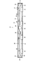
- the whole perspective view showing the heat exchanger concerning one embodiment of the present invention The perspective view which saw through a part of upper tank which constitutes the above-mentioned heat exchanger. Sectional drawing which shows the said upper tank. Sectional drawing which shows the state which the said upper tank inclined.
- FIG. 1 is an overall perspective view showing a radiator (heat exchanger) 10 according to the present embodiment.
- the radiator 10 cools the cooling water (fluid to be heat-exchanged) of the engine mounted on a large dump truck or the like, and flows from the upper tank 11 into which the cooling water from the engine flows and from the upper tank 11
- Vertical flow type comprising a core 12 for cooling the cooling water by heat exchange between the cooling water and the outside air, and a lower tank 13 for collecting the cooling water flowing out from the core 12 and returning it to the water pump on the engine side There is.
- the upper tank 11 will be described later.
- the core 12 is composed of a plurality of (four in the present embodiment) module cores 14 arranged in parallel in the horizontal direction. Since the core 12 is very large, manufacturing the core 12 alone causes manufacturing difficulties. To this end, in the present embodiment, the core 12 is configured by a plurality of modularized module cores 14 so that it can be easily manufactured.
- Each module core 14 is a corrugated core having a plurality of tubes for guiding the cooling water from the upper tank 11 to the lower tank 13 and a wave-like fin interposed between the tubes, like the core used for a normal radiator. Etc. are adopted.
- the frame 20 includes a pair of left and right vertical frames 16, an upper frame 17 connecting the upper ends of the vertical frames 16 through the brackets 19, and a lower frame 18 connecting the lower ends of the vertical frames 16 through the brackets 19. It consists of A stay 21 for fixing the radiator 10 to the vehicle frame is attached to the side surface of the vertical frame 16.
- the lower tank 13 is fixed to the lower surface of the lower frame 18 and formed in a box shape having an internal space communicating with each module core 14. On the side of the lower tank 13 facing the engine side, an outlet pipe 22 to which a radiator hose for cooling water return is connected is attached.
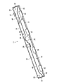
- FIG. 2 shows a perspective view of the upper tank 11 partially transparent.
- the upper tank 11 is formed in a box shape in which a rectangular bottom plate 31 and side plates 32 erected at both ends are covered with a cover plate 33 having a substantially U-shaped cross section, and the flange 33A of the cover plate 33 is used.
- the frame 20 is fixed to the upper frame 17 by a bolt.
- a thin sheet member 34 (FIG. 1) is interposed between the flange 33A and the upper frame 17 in close contact therewith.
- a communication pipe 35 is attached to the bottom plate 31 at a position corresponding to each module core 14 (FIG. 1). That is, the module core 14 is attached to the lower surface side of the bottom plate 31, and the communication pipe 35 communicates the internal space of the upper tank 11 with the upper side of the module core 14. The cooling water flowing into the upper tank 11 is distributed to the respective module cores 14 through the respective communication pipes 35.
- An inlet pipe 36 to which a radiator hose for cooling water inflow is connected is attached to a side surface of the cover plate 33 on the engine side.
- a filler 37 for water absorption is attached to the upper surface on one end side of the cover plate 33.
- stud bolts 38 are attached to the back side of the upper surface in a state of being accommodated in the internal space.
- a hook bolt for hanging is screwed to the stud bolt 38 when the radiator 10 is mounted on a vehicle.
- a mounting boss 39 of a sensor for detecting the temperature of cooling water and various conditions is provided at the center of the cover plate 33.
- a baffle plate 40 for dividing the inner space into a lower space 41 and an upper space 42 along the longitudinal direction is attached by welding.
- the baffle plate 40 moves the air bubbles to the upper space 42 and separates them, and the separated air bubbles are hard to return to the lower space 41. And is prevented from being drawn into the module core 14 from the communication pipe 35.
- a plurality of communication openings 43 are provided at appropriate positions along the longitudinal direction. Air bubbles (including cooling water) move from the lower space 41 to the upper space 42 through the communication opening 43. Moreover, since it is such a structure, in the upper space 42, as shown in FIG. 3, the air pool 44 always exists.
- the baffle plate 40 is located below the surface of the cooling water except for the top of the roof 46 described later.
- bent portions 45 which are bent toward the lower space 41 with respect to the horizontal surface.
- the bending portion 45 is bent at an angle that does not interfere with the communication tubes 35 on both sides. As long as the angle does not interfere with the communication pipe 35, for example, it may be bent at an angle of about 90 degrees. By providing such a bending portion 45, the volume at both ends of the upper space 42 is increased.
- the bending position and the bending angle of the bending portion 45 are also related to the volume to be increased.
- the radiator 10 is also inclined as the vehicle is inclined to the left and right.
- the air reservoir 44 moves to the upper side in the upper space 42 in the upper tank 11, as shown in FIG.
- the lower side of the air reservoir 44 will catch on the communication opening 43, so the air bubbles separated from the air reservoir 44 will be the communication opening It may enter the lower space 41 through 43 and be drawn into the module core 14 from the communication pipe 35.
- air bubbles are present in the tube of the module core 14, so the flow of the cooling water is blocked and the cooling efficiency is reduced. Also, in some cases, air bubbles may reach the water pump and cause cavitation, and it is necessary to prevent such air bubbles from being drawn.
- the bent portions 45 are provided at both ends of the baffle plate 40 to increase the volume.
- the radiator 10 is inclined at about 20 degrees, but in the present embodiment, the upper part of the air pool 44 is not covered by the communication opening 43 even when the radiator 10 is inclined at 25 degrees.
- the end volume of the space 42 is increased, and the bending position and the bending angle of the bending portion 45 are determined so as to secure the increased volume.
- baffle plate 40 even when the radiator 10 is inclined, there is no concern that the air pool 44 gets on the communication opening 43, so that the air bubble is prevented from separating from the air pool 44 and it is prevented from being drawn into the core 12. It is possible to suppress the decrease in cooling efficiency. Further, the provision of the baffle plate 40 enables the cooling water flowing from the inlet pipe 36 to flow smoothly to the module core 14 without ripples. Furthermore, since the cooling water does not wave, it is possible to make it more difficult for air bubbles to be mixed in the cooling water.
- the communication opening 43 closer to the center, it is possible to prevent an air reservoir from sticking to the communication opening 43 when the radiator 10 is inclined, but providing the communication opening 43 only near the center There is a possibility that air bubbles in the inflowing cooling water can not be well led to the upper space 42. From this, it is desirable that the plurality of communication openings 43 be provided apart from one another in the longitudinal direction of the baffle plate 40 as in the present embodiment.
- the upper tank 11 is suppressed to a low upper and lower dimension due to a demand for downsizing of the entire radiator 10.
- an upper space 42 of a predetermined volume is required. For that purpose, it is necessary to lower the position of the baffle plate 40 and to minimize the volume of the lower space 41 as much as possible.
- a roof portion 46 convex upward is provided at a position corresponding to the inlet pipe 36 of the baffle plate 40 so as not to interfere with the inlet pipe 36, and below the roof portion 46.
- the bending portion 45 is provided at the end of the baffle plate 40, but the bending portion is provided so as to be generally inclined from the central position to the end of the baffle plate 40 It is also good.
- the bending part 45 of the said embodiment was the shape inclined diagonally, you may bend vertically as mentioned above, and also may be provided in step shape with a level
- the radiator 10 has been exemplified as the heat exchanger of the present invention, but the heat exchanger of the present invention is not limited to this, and may be an oil cooler or the like, and any heat exchange with the upper tank Can be applied to
- the present invention is applicable not only to a large transport vehicle such as a dump truck, and a construction machine in which a posture change frequently occurs, but can be used for a general truck or a car.
Landscapes
- Engineering & Computer Science (AREA)
- Mechanical Engineering (AREA)
- General Engineering & Computer Science (AREA)
- Physics & Mathematics (AREA)
- Thermal Sciences (AREA)
- Chemical & Material Sciences (AREA)
- Combustion & Propulsion (AREA)
- Heat-Exchange Devices With Radiators And Conduit Assemblies (AREA)
- Details Of Heat-Exchange And Heat-Transfer (AREA)
Abstract
本発明の熱交換器としてのラジエータ(10)は、冷却水が流入するアッパータンク(11)と、アッパータンク(11)からの流体が熱交換されるコア(12)と、コア(12)からの流体を集約するロアータンク(13)とを備え、アッパータンク(11)の内部には、内部空間を下部空間(41)と上部空間(42)とに2分するとともに、下部空間(41)および上部空間(42)を連通する連通開口(43)を有したバッフルプレート(40)が設けられ、バッフルプレート(40)の長手方向の端部には、下部空間(41)側に折曲した折曲部(45)が設けられている。
Description
本発明は、熱交換器に係り、例えばラジエータ等に代表される熱交換器に関する。
従来、ラジエータ、オイルクーラ、インタークーラ(アウタクーラ)等の熱交換器において、熱交換器内に空気が滞留するのを抑制する構造を採用したものはよく知られている(特許文献1,2)。
特許文献1に記載されたものは水冷式インタークーラであるが、このインタークーラでは、冷却水が流入するケーシングの上面において、上向きに膨出した断面円弧状の溝を設けておき、ケーシング内の空気を当該溝を通して冷却水注入口まで導き、ここから外部へ排出する構造が採られている。
特許文献2に記載されたものは横流れ式のオイルクーラであるが、このオイルクーラでは、ヘッダパイプ内に空気が残らないように、ヘッダパイプのキャップとチューブとの隙間を小さくし、この隙間に実質的に空気溜まりが発生しない構造を採用している。
特許文献1に記載されたものは水冷式インタークーラであるが、このインタークーラでは、冷却水が流入するケーシングの上面において、上向きに膨出した断面円弧状の溝を設けておき、ケーシング内の空気を当該溝を通して冷却水注入口まで導き、ここから外部へ排出する構造が採られている。
特許文献2に記載されたものは横流れ式のオイルクーラであるが、このオイルクーラでは、ヘッダパイプ内に空気が残らないように、ヘッダパイプのキャップとチューブとの隙間を小さくし、この隙間に実質的に空気溜まりが発生しない構造を採用している。
しかし、ダンプトラックに用いられるエンジン冷却水用のラジエータを見てみると、悪路走行などにおいて車両が左右に大きく傾斜した場合、ラジエータのアッパータンクでは、もともと存在する空気溜まりが冷却水の液面と共に傾斜してしまい、特許文献1の構造を採用した場合でも、空気を冷却水注入口まで確実に導くことができず、また、特許文献2の構造を採用しても、液面が傾斜することで気泡の発生箇所が安定せず、空気溜まりの発生を完全には防止できない。
そして、アッパータンク内で冷却水の液面が傾斜すると、アッパータンクとコアとを連通させる連通管も空気溜まりに曝されてしまうため、この連通管を通して空気溜まりの空気がラジエータコア内に吸い込まれてしまうことがあり、コアでの冷却水と外気との熱交換が効率よく行われないという問題が生じる。
本発明の目的は、熱交換を効率よく行える熱交換器を提供することにある。
以上の目的を達成するために本発明の熱交換器は、アッパータンク内に存在する空気溜まりを外部に排出したり、空気溜まりの発生そのものを抑制したりするものではなく、大きく姿勢変化した場合でも、存在する空気溜まりがコア内に吸い込まれるのを確実に防止できるよう構成したものであり、具体的には以下の通りである。
すなわち、本発明の熱交換器は、熱交換される流体が流入するアッパータンクと、前記アッパータンクからの流体が熱交換されるコアと、前記コアからの流体を集約するロアータンクとを備え、前記アッパータンクの内部には、内部空間を下部空間と上部空間とに2分するとともに、前記下部空間および上部空間を連通する連通開口を有したバッフルプレートが設けられ、前記バッフルプレートの長手方向の端部には、前記下部空間側に折曲した折曲部が設けられていることを特徴とする。
本発明の熱交換器では、前記折曲部は、水平面に対して前記下部空間側に所定角度傾斜して設けられていることが好ましい。
ここでの「所定角度傾斜して」とは、水平面に対して鋭角の範囲で傾斜していることをいう。
ここでの「所定角度傾斜して」とは、水平面に対して鋭角の範囲で傾斜していることをいう。
以上の本発明によれば、熱交換器が傾斜した場合、空気溜まりが形成される上部空間においては、傾斜した上方側に空気溜まりが移動する。この際、バッフルプレートの端部には折曲部が設けられているので、この折曲部によって空気溜まりが形成される容積が増え、空気溜まりを端部側に寄せて確実に溜めておくことができ、空気溜まりの下方側がバッフルプレートの連通開口にかかるのを防止できる。従って、その連通開口部分で空気溜まりから気泡が分離したり、分離した気泡がコア側に引き込まれたりする心配がなくなり、コアでの冷却効率が低下するのを防止できる。
以上の発明において、折曲部を所定角度傾斜させて設けた場合には、ラジエータが傾斜した状態から水平に戻った場合や、流体面が大きく揺れた場合など、当該折曲部での流体の跳ね返りを抑制でき、空気溜まりから気泡が分離し易い状況となるのを回避できる。
以下、本発明の一実施形態を図面に基づいて説明する。
図1は、本実施形態に係るラジエータ(熱交換器)10を示す全体斜視図である。ラジエータ10は、大型のダンプトラック等に搭載されたエンジンの冷却水(熱交換される流体)を冷却するものであり、エンジンからの冷却水が流入するアッパータンク11と、アッパータンク11内から流れ落ちる冷却水と外気との熱交換により当該冷却水を冷却するコア12と、コア12から流出した冷却水を集約してエンジン側のウォータポンプに戻すロアータンク13とを備えた縦流れ式に構成されている。なお、アッパータンク11については後述する。
図1は、本実施形態に係るラジエータ(熱交換器)10を示す全体斜視図である。ラジエータ10は、大型のダンプトラック等に搭載されたエンジンの冷却水(熱交換される流体)を冷却するものであり、エンジンからの冷却水が流入するアッパータンク11と、アッパータンク11内から流れ落ちる冷却水と外気との熱交換により当該冷却水を冷却するコア12と、コア12から流出した冷却水を集約してエンジン側のウォータポンプに戻すロアータンク13とを備えた縦流れ式に構成されている。なお、アッパータンク11については後述する。
コア12は、本実施形態では、水平方向に並設された複数(本実施形態では4つ)のモジュールコア14で構成されている。コア12が非常に大型であることから、コア12を単体で構成すると製造上の困難性が生じる。このために本実施形態では、コア12をモジュール化された複数のモジュールコア14で構成することとし、容易に製造できるようにしている。
それぞれのモジュールコア14は、通常のラジエータに用いられるコアと同様に、アッパータンク11からの冷却水をロアータンク13に導く複数のチューブと、チューブ間に介装された波状のフィンとを備えるコルゲートコアなどが採用されている。
これらのモジュールコア14は、四周枠組みされた枠体20内に収容されている。この枠体20は、左右一対の縦フレーム16、縦フレーム16の上端間をブラケット19を介して連結する上フレーム17、および縦フレーム16の下端間をブラケット19を介して連結する下フレーム18とで構成されている。縦フレーム16の側面には、ラジエータ10を車両フレームに固定するためのステイ21が取り付けられている。
ロアータンク13は、下フレーム18の下面に固定されており、各モジュールコア14と連通した内部空間を有する箱状に形成されている。ロアータンク13のエンジン側に面した側面には、冷却水戻し用のラジエータホースが接続される出口管22が取り付けられている。
図2には、アッパータンク11を一部透視した斜視図が示されている。アッパータンク11は、矩形状の底プレート31とその両端に立設された側面プレート32とを断面略コ字形状のカバープレート33で覆った箱状とされ、カバープレート33のフランジ33Aを利用して枠体20の上フレーム17にボルトにより固定されている。フランジ33Aと上フレーム17との間には薄板状のシート部材34(図1)が密着した状態で介装されている。
底プレート31には、各モジュールコア14(図1)に対応した位置に連通管35が取り付けられている。すなわち、底プレート31の下面側にはモジュールコア14が取り付けられており、連通管35によりアッパータンク11の内部空間とモジュールコア14の上部側とが連通している。アッパータンク11内に流入した冷却水は、各連通管35を通してそれぞれのモジュールコア14に分配される。
カバープレート33のエンジン側の側面には、冷却水流入用のラジエータホースが接続される入口管36が取り付けられている。カバープレート33の一端側の上面には、吸水用のフィラー37が取り付けられている。カバープレート33の両端側において、上面の裏側には、スタッドボルト38が内部空間に収容された状態で取り付けられている。このスタッドボルト38には、ラジエータ10を車両に搭載する際などに、吊り込み用のフックボルトが螺設される。また、カバープレート33の中央には、冷却水の水温や各種状態を検出するセンサの取付ボス39が設けられている。
このようなアッパータンク11の内部には、内部空間を長手方向に沿って下部空間41および上部空間42に2分するバッフルプレート40が溶接により取り付けられている。このバッフルプレート40は、入口管36を通して下部空間41内に流入した冷却水中に気泡が含まれる場合、この気泡を上部空間42に移動させて分離するとともに、分離した気泡を下部空間41に戻り難くし、連通管35からモジュールコア14に引き込まれるのを防止している。
従ってバッフルプレート40の水平面部分には、長手方向に沿った適宜な位置に複数の連通開口43が設けられている。この連通開口43を通して気泡(冷却水を含む)が下部空間41から上部空間42に移動する。また、このような構成であるから、上部空間42内には常時、図3に示すように、空気溜まり44が存在することになる。ラジエータ10が水平状態にあるとき、バッフルプレート40は、後述の屋根部46の頂部を除き、冷却水の液面よりも下側に位置する。
さらに、本実施形態のバッフルプレート40の両端には、水平面に対して下部空間41側に折曲して傾斜した折曲部45が設けられている。折曲部45は、両側の連通管35と干渉しない程度の角度で折曲している。連通管35と干渉しない角度であれば、例えば90度程度の角度で折曲されていてもよい。このような折曲部45が設けられることにより、上部空間42の両端側での容積が大きくなっている。
そして、折曲部45の折曲位置および折曲角度は、増量させたい容積とも関係している。車両の悪路走行時には、車両が左右に傾くことでラジエータ10も傾く。ラジエータ10が傾くとアッパータンク11内では、図4に示すように、上部空間42内の上方に位置した側に空気溜まり44が移動する。この時、上部空間42の端部(この場合では上方側の端部)の容積が少ないと、空気溜まり44の下方側が連通開口43にかかってしまうため、空気溜まり44から分離した気泡が連通開口43を通って下部空間41に入り込み、連通管35からモジュールコア14に引き込まれる可能性がある。
この状態では、モジュールコア14のチューブ内に気泡が存在することになるから、冷却水の流れが阻害され、冷却効率が低下する。また、場合によっては、気泡がウォータポンプまで達し、キャビテーションの原因になることも考えられ、このような気泡の引込を防止する必要がある。
つまり、本実施形態では、そのような気泡の引込を防止するために、バッフルプレート40の両端に折曲部45を設けて容積アップを図っているのである。この構成により、図4に示すように、空気溜まり44が上方に移動した場合でも、空気を容積増量部分に十分に溜めておくことができ、空気溜まり44の下方側が連通開口43にかからないようになっている。
図4に図示した状態は、ラジエータ10が約20度傾斜した状態であるが、本実施形態では、ラジエータ10が25度傾斜した場合でも、空気溜まり44の下方側が連通開口43にかからないように上部空間42の端部容積が増量されており、そのような増量分の容積が確保されるように折曲部45の折曲位置および折曲角度が決められている。
以上のバッフルプレート40により、ラジエータ10が傾斜した場合でも、空気溜まり44が連通開口43にかかる心配がないから、空気溜まり44から気泡が分離するのを防いでコア12内に引き込まれるのを防止でき、冷却効率の低下を抑制できる。
また、バッフルプレート40が設けられていることで、入口管36から流入した冷却水を、波打つことなくなめらかにモジュールコア14に流すことができる。さらに、冷却水が波打つことがないので、冷却水中に気泡をより混入し難くできる。
また、バッフルプレート40が設けられていることで、入口管36から流入した冷却水を、波打つことなくなめらかにモジュールコア14に流すことができる。さらに、冷却水が波打つことがないので、冷却水中に気泡をより混入し難くできる。
ここで、連通開口43を中央寄りに設けることで、ラジエータ10が傾斜した際の空気溜まりの連通開口43へのかかりを防止することも可能であるが、連通開口43を中央寄りにのみ設けると、流入した冷却水中の気泡を良好に上部空間42に導くことができない可能性がある。このことから、複数の連通開口43を、本実施形態のように、バッフルプレート40の長手方向に互いに離間させて設けることが望ましい。
なお、アッパータンク11は、ラジエータ10全体の小型化の要請から、上下寸法が低く抑えられている。一方で、空気溜まり44を確保するためには所定容積の上部空間42が必要となる。そのためには、バッフルプレート40の位置を低くし、できる限り下部空間41の容積を抑える必要がある。
そこで、本実施形態では、バッフルプレート40の前記入口管36に対応した位置に、当該入口管36と干渉しないように上向きに凸状とされた屋根部46を設け、この屋根部46の下方に入口管36を位置させることで、バッフルプレート40全体の位置を低くしつつ、冷却水を下部空間41に確実に流入させるようにしている。
本発明を実施するための最良の構成、方法などは、以上の記載で開示されているが、本発明は、これに限定されるものではない。すなわち、本発明は、主に特定の実施形態に関して特に図示され、かつ説明されているが、本発明の技術的思想および目的の範囲から逸脱することなく、以上述べた実施形態に対し、形状、数量、その他の詳細な構成において、当業者が様々な変形を加えることができるものである。
従って、上記に開示した形状、数量などを限定した記載は、本発明の理解を容易にするために例示的に記載したものであり、本発明を限定するものではないから、それらの形状、数量などの限定の一部もしくは全部の限定を外した部材の名称での記載は、本発明に含まれるものである。
従って、上記に開示した形状、数量などを限定した記載は、本発明の理解を容易にするために例示的に記載したものであり、本発明を限定するものではないから、それらの形状、数量などの限定の一部もしくは全部の限定を外した部材の名称での記載は、本発明に含まれるものである。
例えば、前記実施形態では、折曲部45がバッフルプレート40の端部に設けられていたが、バッフルプレート40の中央位置から端部に向けて全体的に傾斜するように折曲部を設けてもよい。
また、前記実施形態の折曲部45は斜めに傾斜した形状であったが、前述したように鉛直に折曲していてもよく、さらに、段差を有した階段状に設けられていてもよい。
また、前記実施形態の折曲部45は斜めに傾斜した形状であったが、前述したように鉛直に折曲していてもよく、さらに、段差を有した階段状に設けられていてもよい。
前記実施形態では、本発明の熱交換器としてラジエータ10について例示したが、本発明の熱交換器としてはこれに限定されず、オイルクーラなどであってもよく、アッパータンクを備えたあらゆる熱交換器に適用できる。
本発明は、ダンプトラック等の大型の輸送車両や、姿勢変化が頻繁に生じる建設機械に限らず、一般のトラックあるいは自動車などにも利用可能である。
10…熱交換器、11…アッパータンク、12…コア、13…ロアータンク、40…バッフルプレート、41…下部空間、42…上部空間、43…連通開口、44…空気溜まり、45…折曲部。
Claims (2)
- 熱交換される流体が流入するアッパータンクと、
前記アッパータンクからの流体が熱交換されるコアと、
前記コアからの流体を集約するロアータンクとを備え、
前記アッパータンクの内部には、内部空間を下部空間と上部空間とに2分するとともに、前記下部空間および上部空間を連通する連通開口を有したバッフルプレートが設けられ、
前記バッフルプレートの長手方向の端部には、前記下部空間側に折曲した折曲部が設けられている
ことを特徴とする熱交換器。 - 請求項1に記載の熱交換器において、
前記折曲部は、水平面に対して前記下部空間側に所定角度傾斜して設けられている
ことを特徴とする熱交換器。
Priority Applications (3)
| Application Number | Priority Date | Filing Date | Title |
|---|---|---|---|
| EP10735600.8A EP2392885B1 (en) | 2009-01-27 | 2010-01-20 | Heat exchanger |
| US13/146,237 US9714601B2 (en) | 2009-01-27 | 2010-01-20 | Vertical-flow type heat exchanger having a baffle plate |
| CN2010800054035A CN102292612B (zh) | 2009-01-27 | 2010-01-20 | 热交换器 |
Applications Claiming Priority (2)
| Application Number | Priority Date | Filing Date | Title |
|---|---|---|---|
| JP2009015716A JP5739603B2 (ja) | 2009-01-27 | 2009-01-27 | 熱交換器 |
| JP2009-015716 | 2009-01-27 |
Publications (1)
| Publication Number | Publication Date |
|---|---|
| WO2010087128A1 true WO2010087128A1 (ja) | 2010-08-05 |
Family
ID=42395394
Family Applications (1)
| Application Number | Title | Priority Date | Filing Date |
|---|---|---|---|
| PCT/JP2010/000287 WO2010087128A1 (ja) | 2009-01-27 | 2010-01-20 | 熱交換器 |
Country Status (5)
| Country | Link |
|---|---|
| US (1) | US9714601B2 (ja) |
| EP (1) | EP2392885B1 (ja) |
| JP (1) | JP5739603B2 (ja) |
| CN (1) | CN102292612B (ja) |
| WO (1) | WO2010087128A1 (ja) |
Families Citing this family (8)
| Publication number | Priority date | Publication date | Assignee | Title |
|---|---|---|---|---|
| JP2013002651A (ja) * | 2011-06-13 | 2013-01-07 | Showa Denko Kk | 熱交換器 |
| JP5712973B2 (ja) * | 2012-06-28 | 2015-05-07 | カルソニックカンセイ株式会社 | 車両用熱交換装置 |
| US10465996B2 (en) * | 2015-06-10 | 2019-11-05 | Mahle International Gmbh | Method of manufacturing a heat exchanger assembly having a sheet metal distributor/collector tube |
| CN108662812B (zh) * | 2017-03-31 | 2022-02-18 | 开利公司 | 流平衡器和具有该流平衡器的蒸发器 |
| JP2019211094A (ja) * | 2018-05-31 | 2019-12-12 | 株式会社ティラド | 複合型熱交換器のフレーム構造 |
| KR102506944B1 (ko) * | 2018-09-18 | 2023-03-07 | 현대자동차 주식회사 | 통합 라디에이터 및 이를 포함하는 냉각 시스템 |
| CN112038059A (zh) * | 2020-08-28 | 2020-12-04 | 北京峰曲睿泽房地产经纪有限公司 | 一种船用风水冷变压器 |
| US12066224B2 (en) * | 2022-06-03 | 2024-08-20 | Trane International Inc. | Evaporator charge management and method for controlling the same |
Citations (4)
| Publication number | Priority date | Publication date | Assignee | Title |
|---|---|---|---|---|
| JPS50118557U (ja) * | 1974-03-11 | 1975-09-27 | ||
| JPS5538114U (ja) * | 1978-08-31 | 1980-03-11 | ||
| FR2478807A1 (fr) * | 1980-03-21 | 1981-09-25 | Deville Ste Indle | Boite collectrice de raccordement pour appareil d'echanges thermiques |
| JPS6050387U (ja) * | 1983-09-13 | 1985-04-09 | カルソニックカンセイ株式会社 | 熱交換器 |
Family Cites Families (34)
| Publication number | Priority date | Publication date | Assignee | Title |
|---|---|---|---|---|
| US1344351A (en) | 1916-12-13 | 1920-06-22 | Holt Mfg Co | Cooling-radiator |
| US1684083A (en) * | 1927-06-02 | 1928-09-11 | Samuel C Bloom | Refrigerating coil |
| GB473483A (en) * | 1936-04-08 | 1937-10-08 | James Edwin Ellor | Improvements in header tanks for liquid cooled internal combustion engines |
| US2357156A (en) * | 1942-03-02 | 1944-08-29 | Mcquay Inc | Radiator |
| US2672131A (en) * | 1950-05-16 | 1954-03-16 | Everett N Wood | Cooling system |
| US2628079A (en) * | 1950-06-22 | 1953-02-10 | Ford Motor Co | Radiator construction |
| US3132690A (en) * | 1960-08-11 | 1964-05-12 | Int Harvester Co | Radiator deaeration baffle |
| US3254707A (en) * | 1964-03-19 | 1966-06-07 | Hunt Foods And Ind Inc | Heat exchanger and cooling apparatus |
| US3282333A (en) * | 1965-07-26 | 1966-11-01 | Perfex Corp | Radiator construction |
| US3447602A (en) * | 1967-06-22 | 1969-06-03 | David Dalin | Heat exchanger especially adapted for indirect heat transfer by convection |
| DE2419266C3 (de) * | 1974-04-22 | 1978-04-27 | Daimler-Benz Ag, 7000 Stuttgart | Ausgleichsgefäß fur den Volumenausgleich und die Luftabscheidung eines in einem Kreislauf insbesondere die Maschinenkühlraume einer flüssigkeitsgekühlten Brennkraftmaschine durchströmenden flüssigen Wärmeträgers |
| IT1041062B (it) * | 1974-08-03 | 1980-01-10 | Sueddeutsche Kuehler Behr | Serbatoio di compensazione per liquido refrigerante particolarmente in motori a combustione interna |
| FR2428812A1 (fr) * | 1978-06-15 | 1980-01-11 | Ferodo Sa | Dispositif de vase d'expansion et boite a eau pour echangeur de chaleur tel qu'un radiateur de vehicule automobile |
| DE2840813C2 (de) * | 1978-09-20 | 1981-05-27 | Kühlerfabrik Längerer & Reich, 7024 Filderstadt | Kühler mit vertikalen Kühlrohren und einer Entlüftungseinrichtung |
| JP2601637Y2 (ja) | 1992-05-18 | 1999-11-29 | 昭和アルミニウム株式会社 | 熱交換器 |
| JP3561957B2 (ja) * | 1994-07-22 | 2004-09-08 | 株式会社デンソー | 受液器一体型冷媒凝縮器 |
| JPH10185463A (ja) * | 1996-12-19 | 1998-07-14 | Sanden Corp | 熱交換器 |
| US5941303A (en) * | 1997-11-04 | 1999-08-24 | Thermal Components | Extruded manifold with multiple passages and cross-counterflow heat exchanger incorporating same |
| JPH11351787A (ja) * | 1998-06-09 | 1999-12-24 | Zexel:Kk | 熱交換器 |
| JP2001116486A (ja) | 1999-10-20 | 2001-04-27 | Sanden Corp | オイルクーラ |
| FR2805606B1 (fr) * | 2000-02-24 | 2002-07-05 | Valeo Thermique Moteur Sa | Boite collectrice a tubulure integree pour echangeur de chaleur |
| JP2001248988A (ja) * | 2000-03-06 | 2001-09-14 | Mitsubishi Heavy Ind Ltd | 熱交換器 |
| TW552382B (en) * | 2001-06-18 | 2003-09-11 | Showa Dendo Kk | Evaporator, manufacturing method of the same, header for evaporator and refrigeration system |
| JP2008224213A (ja) * | 2001-06-18 | 2008-09-25 | Showa Denko Kk | 蒸発器 |
| US6896037B2 (en) * | 2002-10-29 | 2005-05-24 | Duramax Marine, Llc | Keel cooler with fluid flow diverter |
| DE502004007785D1 (de) * | 2003-05-16 | 2008-09-18 | Peter Hampel | Wärmetauscher |
| AU2004261893A1 (en) * | 2003-08-01 | 2005-02-10 | Showa Denko K.K. | Heat exchanger |
| US20070256821A1 (en) * | 2004-09-08 | 2007-11-08 | Calsonic Kansei Corporation | Header Tank for Heat Exchanger |
| US7275394B2 (en) * | 2005-04-22 | 2007-10-02 | Visteon Global Technologies, Inc. | Heat exchanger having a distributer plate |
| JP4840681B2 (ja) * | 2005-09-16 | 2011-12-21 | 株式会社ヴァレオジャパン | 熱交換器 |
| CN2854805Y (zh) * | 2005-12-09 | 2007-01-03 | 永彰机电股份有限公司 | 具储液槽的热交换装置 |
| US7484555B2 (en) * | 2006-07-25 | 2009-02-03 | Delphi Technologies, Inc. | Heat exchanger assembly |
| JP5002797B2 (ja) * | 2007-03-16 | 2012-08-15 | 株式会社ケーヒン・サーマル・テクノロジー | 熱交換器 |
| US7921558B2 (en) * | 2008-01-09 | 2011-04-12 | Delphi Technologies, Inc. | Non-cylindrical refrigerant conduit and method of making same |
-
2009
- 2009-01-27 JP JP2009015716A patent/JP5739603B2/ja not_active Expired - Fee Related
-
2010
- 2010-01-20 WO PCT/JP2010/000287 patent/WO2010087128A1/ja active Application Filing
- 2010-01-20 EP EP10735600.8A patent/EP2392885B1/en not_active Not-in-force
- 2010-01-20 US US13/146,237 patent/US9714601B2/en active Active
- 2010-01-20 CN CN2010800054035A patent/CN102292612B/zh not_active Expired - Fee Related
Patent Citations (4)
| Publication number | Priority date | Publication date | Assignee | Title |
|---|---|---|---|---|
| JPS50118557U (ja) * | 1974-03-11 | 1975-09-27 | ||
| JPS5538114U (ja) * | 1978-08-31 | 1980-03-11 | ||
| FR2478807A1 (fr) * | 1980-03-21 | 1981-09-25 | Deville Ste Indle | Boite collectrice de raccordement pour appareil d'echanges thermiques |
| JPS6050387U (ja) * | 1983-09-13 | 1985-04-09 | カルソニックカンセイ株式会社 | 熱交換器 |
Also Published As
| Publication number | Publication date |
|---|---|
| CN102292612B (zh) | 2013-07-10 |
| JP2010175094A (ja) | 2010-08-12 |
| EP2392885A4 (en) | 2014-06-04 |
| CN102292612A (zh) | 2011-12-21 |
| US9714601B2 (en) | 2017-07-25 |
| EP2392885B1 (en) | 2018-11-21 |
| EP2392885A1 (en) | 2011-12-07 |
| US20110277979A1 (en) | 2011-11-17 |
| JP5739603B2 (ja) | 2015-06-24 |
Similar Documents
| Publication | Publication Date | Title |
|---|---|---|
| WO2010087128A1 (ja) | 熱交換器 | |
| JP5668610B2 (ja) | 水冷コンデンサ | |
| JP5821795B2 (ja) | 熱交換器 | |
| JP6505160B2 (ja) | 車両用熱交換装置 | |
| JP2007218455A (ja) | 熱交換器 | |
| US20090260787A1 (en) | Heat exchanger for motor vehicles | |
| US20210331579A1 (en) | Heat exchanger | |
| JP2009121728A (ja) | 多面体構造の熱交換器及びその製造方法 | |
| JP2008291694A (ja) | ファンシュラウド構造 | |
| JP2011185489A (ja) | 複合型熱交換器 | |
| JP2004060933A (ja) | 複数熱交換器の一体化構造 | |
| JP4613832B2 (ja) | 熱交換器 | |
| JP2022016079A (ja) | 冷却ユニット | |
| JPH11287586A (ja) | 熱交換器 | |
| JP4420689B2 (ja) | 自動車のフロント構造 | |
| JP4333521B2 (ja) | 二輪車用熱交換器 | |
| JPS6335255Y2 (ja) | ||
| KR101932194B1 (ko) | 열교환기 | |
| KR101719638B1 (ko) | 라디에이터와 팬 쉬라우드의 조립체 | |
| JP2008114255A (ja) | 熱交換器用チューブ | |
| JPS6328715Y2 (ja) | ||
| JP2009074768A (ja) | 熱交換器 | |
| JPH0122800Y2 (ja) | ||
| JPS6078296A (ja) | 車両用熱交換器 | |
| JP2017096591A (ja) | 熱交換器 |
Legal Events
| Date | Code | Title | Description |
|---|---|---|---|
| WWE | Wipo information: entry into national phase |
Ref document number: 201080005403.5 Country of ref document: CN |
|
| 121 | Ep: the epo has been informed by wipo that ep was designated in this application |
Ref document number: 10735600 Country of ref document: EP Kind code of ref document: A1 |
|
| WWE | Wipo information: entry into national phase |
Ref document number: 13146237 Country of ref document: US |
|
| NENP | Non-entry into the national phase |
Ref country code: DE |
|
| WWE | Wipo information: entry into national phase |
Ref document number: 2010735600 Country of ref document: EP |