WO2010035602A1 - 硫化リチウム-炭素複合体、その製造方法、及び該複合体を用いるリチウムイオン二次電池 - Google Patents
硫化リチウム-炭素複合体、その製造方法、及び該複合体を用いるリチウムイオン二次電池 Download PDFInfo
- Publication number
- WO2010035602A1 WO2010035602A1 PCT/JP2009/064721 JP2009064721W WO2010035602A1 WO 2010035602 A1 WO2010035602 A1 WO 2010035602A1 JP 2009064721 W JP2009064721 W JP 2009064721W WO 2010035602 A1 WO2010035602 A1 WO 2010035602A1
- Authority
- WO
- WIPO (PCT)
- Prior art keywords
- carbon
- lithium sulfide
- lithium
- positive electrode
- composite
- Prior art date
- Legal status (The legal status is an assumption and is not a legal conclusion. Google has not performed a legal analysis and makes no representation as to the accuracy of the status listed.)
- Ceased
Links
Images



Classifications
-
- H—ELECTRICITY
- H01—ELECTRIC ELEMENTS
- H01M—PROCESSES OR MEANS, e.g. BATTERIES, FOR THE DIRECT CONVERSION OF CHEMICAL ENERGY INTO ELECTRICAL ENERGY
- H01M4/00—Electrodes
- H01M4/02—Electrodes composed of, or comprising, active material
- H01M4/13—Electrodes for accumulators with non-aqueous electrolyte, e.g. for lithium-accumulators; Processes of manufacture thereof
- H01M4/136—Electrodes based on inorganic compounds other than oxides or hydroxides, e.g. sulfides, selenides, tellurides, halogenides or LiCoFy
-
- C—CHEMISTRY; METALLURGY
- C01—INORGANIC CHEMISTRY
- C01B—NON-METALLIC ELEMENTS; COMPOUNDS THEREOF; METALLOIDS OR COMPOUNDS THEREOF NOT COVERED BY SUBCLASS C01C
- C01B17/00—Sulfur; Compounds thereof
- C01B17/22—Alkali metal sulfides or polysulfides
-
- C—CHEMISTRY; METALLURGY
- C01—INORGANIC CHEMISTRY
- C01B—NON-METALLIC ELEMENTS; COMPOUNDS THEREOF; METALLOIDS OR COMPOUNDS THEREOF NOT COVERED BY SUBCLASS C01C
- C01B32/00—Carbon; Compounds thereof
-
- H—ELECTRICITY
- H01—ELECTRIC ELEMENTS
- H01M—PROCESSES OR MEANS, e.g. BATTERIES, FOR THE DIRECT CONVERSION OF CHEMICAL ENERGY INTO ELECTRICAL ENERGY
- H01M4/00—Electrodes
- H01M4/02—Electrodes composed of, or comprising, active material
- H01M4/04—Processes of manufacture in general
- H01M4/043—Processes of manufacture in general involving compressing or compaction
-
- H—ELECTRICITY
- H01—ELECTRIC ELEMENTS
- H01M—PROCESSES OR MEANS, e.g. BATTERIES, FOR THE DIRECT CONVERSION OF CHEMICAL ENERGY INTO ELECTRICAL ENERGY
- H01M4/00—Electrodes
- H01M4/02—Electrodes composed of, or comprising, active material
- H01M4/04—Processes of manufacture in general
- H01M4/0438—Processes of manufacture in general by electrochemical processing
-
- H—ELECTRICITY
- H01—ELECTRIC ELEMENTS
- H01M—PROCESSES OR MEANS, e.g. BATTERIES, FOR THE DIRECT CONVERSION OF CHEMICAL ENERGY INTO ELECTRICAL ENERGY
- H01M4/00—Electrodes
- H01M4/02—Electrodes composed of, or comprising, active material
- H01M4/13—Electrodes for accumulators with non-aqueous electrolyte, e.g. for lithium-accumulators; Processes of manufacture thereof
- H01M4/133—Electrodes based on carbonaceous material, e.g. graphite-intercalation compounds or CFx
-
- H—ELECTRICITY
- H01—ELECTRIC ELEMENTS
- H01M—PROCESSES OR MEANS, e.g. BATTERIES, FOR THE DIRECT CONVERSION OF CHEMICAL ENERGY INTO ELECTRICAL ENERGY
- H01M4/00—Electrodes
- H01M4/02—Electrodes composed of, or comprising, active material
- H01M4/13—Electrodes for accumulators with non-aqueous electrolyte, e.g. for lithium-accumulators; Processes of manufacture thereof
- H01M4/139—Processes of manufacture
- H01M4/1393—Processes of manufacture of electrodes based on carbonaceous material, e.g. graphite-intercalation compounds or CFx
-
- H—ELECTRICITY
- H01—ELECTRIC ELEMENTS
- H01M—PROCESSES OR MEANS, e.g. BATTERIES, FOR THE DIRECT CONVERSION OF CHEMICAL ENERGY INTO ELECTRICAL ENERGY
- H01M4/00—Electrodes
- H01M4/02—Electrodes composed of, or comprising, active material
- H01M4/13—Electrodes for accumulators with non-aqueous electrolyte, e.g. for lithium-accumulators; Processes of manufacture thereof
- H01M4/139—Processes of manufacture
- H01M4/1397—Processes of manufacture of electrodes based on inorganic compounds other than oxides or hydroxides, e.g. sulfides, selenides, tellurides, halogenides or LiCoFy
-
- H—ELECTRICITY
- H01—ELECTRIC ELEMENTS
- H01M—PROCESSES OR MEANS, e.g. BATTERIES, FOR THE DIRECT CONVERSION OF CHEMICAL ENERGY INTO ELECTRICAL ENERGY
- H01M4/00—Electrodes
- H01M4/02—Electrodes composed of, or comprising, active material
- H01M4/36—Selection of substances as active materials, active masses, active liquids
- H01M4/58—Selection of substances as active materials, active masses, active liquids of inorganic compounds other than oxides or hydroxides, e.g. sulfides, selenides, tellurides, halogenides or LiCoFy; of polyanionic structures, e.g. phosphates, silicates or borates
- H01M4/581—Chalcogenides or intercalation compounds thereof
-
- H—ELECTRICITY
- H01—ELECTRIC ELEMENTS
- H01M—PROCESSES OR MEANS, e.g. BATTERIES, FOR THE DIRECT CONVERSION OF CHEMICAL ENERGY INTO ELECTRICAL ENERGY
- H01M4/00—Electrodes
- H01M4/02—Electrodes composed of, or comprising, active material
- H01M4/36—Selection of substances as active materials, active masses, active liquids
- H01M4/58—Selection of substances as active materials, active masses, active liquids of inorganic compounds other than oxides or hydroxides, e.g. sulfides, selenides, tellurides, halogenides or LiCoFy; of polyanionic structures, e.g. phosphates, silicates or borates
- H01M4/583—Carbonaceous material, e.g. graphite-intercalation compounds or CFx
- H01M4/587—Carbonaceous material, e.g. graphite-intercalation compounds or CFx for inserting or intercalating light metals
-
- C—CHEMISTRY; METALLURGY
- C01—INORGANIC CHEMISTRY
- C01P—INDEXING SCHEME RELATING TO STRUCTURAL AND PHYSICAL ASPECTS OF SOLID INORGANIC COMPOUNDS
- C01P2002/00—Crystal-structural characteristics
- C01P2002/70—Crystal-structural characteristics defined by measured X-ray, neutron or electron diffraction data
- C01P2002/72—Crystal-structural characteristics defined by measured X-ray, neutron or electron diffraction data by d-values or two theta-values, e.g. as X-ray diagram
-
- C—CHEMISTRY; METALLURGY
- C01—INORGANIC CHEMISTRY
- C01P—INDEXING SCHEME RELATING TO STRUCTURAL AND PHYSICAL ASPECTS OF SOLID INORGANIC COMPOUNDS
- C01P2006/00—Physical properties of inorganic compounds
- C01P2006/11—Powder tap density
-
- C—CHEMISTRY; METALLURGY
- C01—INORGANIC CHEMISTRY
- C01P—INDEXING SCHEME RELATING TO STRUCTURAL AND PHYSICAL ASPECTS OF SOLID INORGANIC COMPOUNDS
- C01P2006/00—Physical properties of inorganic compounds
- C01P2006/12—Surface area
-
- C—CHEMISTRY; METALLURGY
- C01—INORGANIC CHEMISTRY
- C01P—INDEXING SCHEME RELATING TO STRUCTURAL AND PHYSICAL ASPECTS OF SOLID INORGANIC COMPOUNDS
- C01P2006/00—Physical properties of inorganic compounds
- C01P2006/40—Electric properties
-
- Y—GENERAL TAGGING OF NEW TECHNOLOGICAL DEVELOPMENTS; GENERAL TAGGING OF CROSS-SECTIONAL TECHNOLOGIES SPANNING OVER SEVERAL SECTIONS OF THE IPC; TECHNICAL SUBJECTS COVERED BY FORMER USPC CROSS-REFERENCE ART COLLECTIONS [XRACs] AND DIGESTS
- Y02—TECHNOLOGIES OR APPLICATIONS FOR MITIGATION OR ADAPTATION AGAINST CLIMATE CHANGE
- Y02E—REDUCTION OF GREENHOUSE GAS [GHG] EMISSIONS, RELATED TO ENERGY GENERATION, TRANSMISSION OR DISTRIBUTION
- Y02E60/00—Enabling technologies; Technologies with a potential or indirect contribution to GHG emissions mitigation
- Y02E60/10—Energy storage using batteries
-
- Y—GENERAL TAGGING OF NEW TECHNOLOGICAL DEVELOPMENTS; GENERAL TAGGING OF CROSS-SECTIONAL TECHNOLOGIES SPANNING OVER SEVERAL SECTIONS OF THE IPC; TECHNICAL SUBJECTS COVERED BY FORMER USPC CROSS-REFERENCE ART COLLECTIONS [XRACs] AND DIGESTS
- Y02—TECHNOLOGIES OR APPLICATIONS FOR MITIGATION OR ADAPTATION AGAINST CLIMATE CHANGE
- Y02P—CLIMATE CHANGE MITIGATION TECHNOLOGIES IN THE PRODUCTION OR PROCESSING OF GOODS
- Y02P70/00—Climate change mitigation technologies in the production process for final industrial or consumer products
- Y02P70/50—Manufacturing or production processes characterised by the final manufactured product
Definitions
- the present invention relates to a composite of lithium sulfide and carbon, a production method thereof, and an application thereof.
- lithium ion secondary batteries used for them are increasingly required to have higher capacities.
- the increase in capacity of the positive electrode is delayed compared to the negative electrode, and the lithium nickelate-based material, which is said to have a relatively high capacity, is about 190 to 220 mAh / g.
- sulfur has a high theoretical capacity of about 1670 mAh / g and is one of the promising candidates for high-capacity electrode materials.
- sulfur alone has low electron conductivity and does not contain lithium, lithium or an alloy containing lithium must be used for the negative electrode, which has a drawback that the selection range of the negative electrode is narrow.
- lithium sulfide contains lithium, alloys such as graphite and silicon can be used for the negative electrode, and the selection range of the negative electrode is greatly expanded, and a short circuit due to generation of dendrite by using metallic lithium. The dangers such as can be avoided.
- lithium sulfide also has a drawback of low electronic conductivity, and is hardly charged / discharged only by mixing carbon powder as a conductive material (see Non-Patent Document 1 below). For this reason, in order to improve the performance of the sulfur-based positive electrode material, a technique for imparting electronic conductivity to lithium sulfide is indispensable.
- Non-Patent Documents 2 and 3 As an attempt to improve the electronic conductivity of lithium sulfide, a method has been reported in which copper powder is used as a conductive material and is combined with lithium sulfide (see Non-Patent Documents 2 and 3 below).
- the transition metal powder such as copper powder is generally heavier than lithium sulfide, which causes a reduction in the weight energy density of the battery.
- the price per weight is higher than that of carbon powder, leading to high battery costs. For this reason, carbon powder is more advantageous from the viewpoint of industrial production, but no composite of lithium sulfide and carbon has been reported so far.
- Patent Document 1 As for carbon complexing of sulfur alone, for example, a method of mechanical milling treatment of both in an air atmosphere is known (see Patent Document 1 below), but a lithium sulfide-carbon composite is prepared by such a dry method. There are no reports. In addition, a method of supporting lithium polysulfide (such as Li 2 S 12 ) on carbon using liquid phase reaction has been reported (see Patent Document 2 below), but lithium sulfide (Li 2 S) and carbon are combined. No method has been reported.
- Li 2 lithium polysulfide
- the present invention has been made in view of the current state of the prior art described above, and its main purpose is to improve the electronic conductivity of lithium sulfide expected to be put to practical use as a high-capacity positive electrode active material, thereby improving the lithium conductivity. It is to provide a method capable of further improving the performance as a positive electrode active material for an ion secondary battery. Furthermore, the other object of this invention is to provide the novel lithium ion secondary battery which can utilize effectively the outstanding performance about the positive electrode active material obtained by the manufacturing method of this invention.
- the present inventor has intensively studied to achieve the above-mentioned purpose.
- lithium sulfide and a carbon material are used as raw materials, filled in a conductive container, and subjected to a heating reaction by applying a direct current pulse current under pressure in a non-oxidizing atmosphere with a low moisture content.
- a dense composite in which lithium sulfide and a carbon material are firmly bonded can be obtained.
- complex is used as a positive electrode active material of a lithium ion secondary battery, it discovered that electronic conductivity improved and it can exhibit the outstanding performance as a positive electrode active material for high capacity
- the present invention provides the following lithium sulfide and carbon composite, its production method and its use.
- a mixture of lithium sulfide and a carbon material having a specific surface area of 60 m 2 / g or more is filled in a conductive mold, and a DC pulse current is applied in a state where the mixture is pressurized in a non-oxidizing atmosphere.
- the method for producing a lithium sulfide-carbon composite according to Item 1 wherein lithium sulfide and a carbon material are reacted by heating. 3.
- Item 3 The method according to Item 2, wherein the carbon material is acetylene black, and the amount of the carbon material used is 15 to 70% by mass based on the total amount of lithium sulfide and the carbon material. 4).
- a positive electrode active material for a lithium ion secondary battery comprising the lithium sulfide-carbon composite according to item 1. 6).
- a lithium ion secondary battery comprising the positive electrode active material according to item 5 as a constituent element. 7).
- An all solid lithium ion secondary battery comprising the positive electrode active material according to Item 5 and a lithium ion conductive solid electrolyte as constituent elements. 8).
- lithium sulfide and a carbon material are used as starting materials.
- Lithium sulfide is represented by the chemical formula: Li 2 S, and there is no particular limitation on the shape thereof. However, it is usually preferable to use a powdered powder having an average particle size of about 1 to 50 ⁇ m. In the present specification, the average particle size is a particle size at which the cumulative frequency distribution is 50% in the particle size distribution measurement by a dry laser diffraction / scattering method.
- a carbon material having a specific surface area of about 60 m 2 / g or more is preferably used, and a carbon material having a specific surface area of about 65 m 2 / g or more is more preferably used.
- a carbon material with a large specific surface area that is, ultrafine carbon powder
- the conductive network in the composite becomes denser, and lithium sulfide particles isolated from the conductive network are reduced and used as an active material.
- a high capacity value can be expected by increasing the number of lithium sulfide particles that can be produced.
- the upper limit of the specific surface area is not particularly limited, but usually a surface area of about 300 m 2 / g or less may be used.
- a carbon powder having a specific surface area larger than this has a sphere equivalent particle size of 10 nm or less, and is difficult to handle due to problems such as scattering, which complicates the compositing process.
- the specific surface area is a BET specific surface area measured by a nitrogen adsorption method.
- acetylene black, ketjen black, VGCF (vapor phase process carbon fiber), coke-based or pitch-based carbon material fiber, and the like are preferable.
- the mixing ratio of the lithium sulfide and the carbon material is preferably about 15 to 70% by mass, more preferably about 30 to 70% by mass, with the total amount of both being 100% by mass, More preferably, it is about 67% by mass.
- the carbon material content is low, for example, in the range of about 15 to 30% by mass, the generation of by-products such as lithium carbonate is produced particularly when producing a composite with lithium sulfide. Therefore, it is possible to obtain a composite positive electrode material that has a small weight energy density and a high volume energy density and an excellent conductive network.
- a starting material composed of lithium sulfide and a carbon material is sufficiently mixed in a non-oxidizing atmosphere, and then conductive.
- the mixture is pressurized and a direct current pulse current called a discharge plasma sintering method, a pulse current sintering method, a plasma activated sintering method, or the like is applied.
- the raw material mixture is sintered by an electric current sintering method in which electric current is applied. As a result, a target high-density lithium sulfide-carbon composite can be obtained.
- a conductive mold having a predetermined shape is filled with a mixture of lithium sulfide and carbon material as raw materials, and a pulse-like ON ⁇ is applied while being pressurized in a non-oxidizing atmosphere.
- a pulse-like ON ⁇ is applied while being pressurized in a non-oxidizing atmosphere.
- an apparatus for performing energization processing it is possible to pressurize the raw material lithium sulfide and carbon material, supply current sufficient to cause discharge, and further adjust the container filled with the raw material to a predetermined atmosphere
- a commercially available current sintering apparatus discharge plasma sintering apparatus
- Such an electric sintering apparatus and its operating principle are described in, for example, Japanese Patent Laid-Open No. 10-251070.
- FIG. 1 showing a schematic diagram of an example of a discharge plasma sintering apparatus.
- a discharge plasma sintering apparatus 1 shown in FIG. 1 has a conductive die (die) 3 loaded with a raw material mixture 2 and a pair of upper and lower punches 4 and 5.
- the punches 4 and 5 are supported by punch electrodes 6 and 7, respectively, and a pulse current is applied through the punch electrodes 6 and 7 while pressurizing the raw material 2 loaded in the conductive die (die) 3. Can be supplied.
- Examples of the material of the conductive type (die) used for filling the raw material include materials that have electronic conductivity and do not easily react with lithium sulfide, such as cemented carbides such as carbon and tungsten carbide, A mixture, a mixture obtained by adding a reinforcing material such as silicon nitride to these, and the like can be used in appropriate combination.
- Non-oxidizing atmosphere for example, a reduced pressure state with a sufficiently low oxygen concentration may be used, but an inert gas atmosphere such as Ar or N 2 is preferable, and an Ar atmosphere is particularly preferable.
- the atmosphere preferably has a low water content, and in particular, the dew point is preferably about ⁇ 60 ° C. or less.
- the heating reaction between lithium sulfide and the carbon material must also be performed in a non-oxidizing atmosphere.
- the non-oxidizing atmosphere may be a reduced pressure state in which the oxygen concentration is sufficiently low as in the case of filling the mold, but an inert gas atmosphere such as Ar or N 2 is preferable, and an Ar atmosphere is particularly preferable.
- the current-carrying portion including the conductive mold 3, the current-carrying punches 4 and 5, and the punch electrodes 6 and 7 is housed in a water-cooled vacuum chamber 8. It can be adjusted to a predetermined atmosphere by the mechanism 15. Therefore, the atmosphere control mechanism 15 may be used to adjust the inside of the chamber to a non-oxidizing atmosphere.
- the control device 12 drives and controls the pressurizing mechanism 13, the pulse power supply 11, the atmosphere control mechanism 15, the water cooling mechanisms 16 and 10, and the temperature measuring device 17.
- the control device 12 is configured to drive the pressurizing mechanism 13 so that the punch electrodes 6 and 7 pressurize the raw material mixture at a predetermined pressure.
- a pressure of about 10 MPa or more, preferably about 30 MPa or more is applied to the mixture of the raw material lithium sulfide and the carbon material. If the pressure at this time is too low, bonding between lithium sulfide and carbon material particles becomes insufficient, which is not preferable.
- the upper limit of the pressure is not particularly limited, but is usually about 500 MPa, preferably about 450 MPa.
- the heating temperature during the energization treatment varies depending on the particle size of the lithium sulfide and carbon material used as raw materials and the surface condition thereof, but is usually about 600 ° C. or higher, preferably about 700 ° C. or higher. When the heating temperature is too low, bonding between lithium sulfide and carbon material particles becomes insufficient, which is not preferable.
- the upper limit of the heating temperature is not particularly limited. For example, a good composite can be obtained even at a heating temperature of about 1400 ° C.
- the heating temperature is about 600 to 1000 ° C.
- the electron conductivity is moderately improved, and excellent performance as a positive electrode active material for a high capacity lithium secondary battery can be exhibited.
- the heating temperature is about 700 to 900 ° C.
- a high-performance positive electrode active material can be obtained.
- the pulse current to be energized for heating for example, a pulsed ON-OFF DC current having a pulse width of about 2 to 3 milliseconds and a cycle of about 3 Hz to 300 Hz can be used. Since the current value varies depending on the type and size of the mold material, the rate of temperature increase, etc., the current value may be controlled so as to reach a predetermined temperature by increasing or decreasing the current value while monitoring the temperature of the mold material.
- a current value of about 100 to 600 A is preferable, and when the temperature is raised at 200 ° C./min, 100 to The current value is preferably about 1000 A, and when the temperature is raised at 10 ° C./min using a mold material having an inner diameter of about 100 mm, the current value is preferably about 1000 to 8000 A.
- the sintering time by electric current sintering varies depending on the amount of raw materials used, the sintering temperature, etc., and thus cannot be specified in general, but it is usually sufficient to heat until reaching the heating temperature range described above, and the temperature range described above. If it reaches
- the discharge phenomenon generated in the particle gap between the filled lithium sulfide and the carbon material is utilized, and discharge plasma, discharge shock pressure, etc.
- the particle surface purification activation action, the electric field diffusion effect caused by the electric field, the thermal diffusion effect due to Joule heat, the plastic deformation pressure due to pressurization, etc. serve as the driving force for bonding, and the interparticle bonding is promoted.
- a composite of carbon materials can be obtained.
- the obtained lithium sulfide-carbon composite is cooled, removed from the mold, and lightly pulverized with, for example, a mortar, etc., so that the lithium sulfide and the carbon material are firmly bonded to each other, and the high-density lithium sulfide-carbon composite powder Can be recovered.
- the above process may be scaled up using a large mold material.
- Lithium sulfide-carbon composite Lithium sulfide and carbon composite obtained by the above-mentioned method is a highly conductive network in which lithium sulfide and carbon particles as raw materials are strongly bonded to each other and densified. Is formed. For this reason, when it uses as an active material for lithium secondary battery positive electrodes, electronic conductivity improves and it can exhibit the outstanding performance as a high capacity
- the lithium sulfide-carbon composite obtained by the above-described method becomes a high-density composite containing 15 to 70% by mass of carbon, with the total amount of the product being 100% by mass, as in the raw material blending.
- lithium sulfide partially decomposes during the electric current sintering process, and lithium isolated from sulfur atoms reacts with carbon and slight residual oxygen to produce lithium carbonate.
- the resulting lithium sulfide-carbon composite May remain on the body.
- the amount of lithium sulfide corresponding to the amount of lithium carbonate produced decreases.
- About lithium carbonate if it is about 5 mass% or less, there is almost no influence on a charge / discharge characteristic.
- a composite having a carbon content of about 15 to 30% by weight is a high-capacity positive electrode active material because the amount of lithium carbonate that is not involved in charge / discharge is small.
- the resulting composite is a solid joint of lithium sulfide and a carbon material, with a greatly improved density compared to the raw material mixture, and about 0.4 g / cm 3 or more when the carbon content is 30% by mass or more.
- the carbon content is less than 30% by mass, it has an unprecedented high density of about 0.5 g / cm 3 or more.
- the upper limit of the tap density is not particularly limited, and it varies depending on the temperature, pressure, and the like at the time of pressure-electric current sintering, but usually the tap density is about 1.0 g / cm 3 or less.
- the tap density in the present specification is about 0.2 to about after the sample is pulverized by hand with a mortar or the like under a low moisture content / non-oxidizing atmosphere with a dew point of ⁇ 60 ° C. or less, and passed through a sieve with an opening of 100 ⁇ m. This is the value measured after putting a 1.0 g sample into a 10 mL graduated cylinder and tapping 100 times.
- the lithium sulfide-carbon composite obtained by the method of the present invention can be effectively used as an active material for a positive electrode for a lithium ion secondary battery.
- a lithium ion secondary battery using the composite can be manufactured by a known method. That is, except that the composite obtained by the method of the present invention is used as a positive electrode active material, a known metal lithium, a carbon-based material (activated carbon, graphite) or the like is used as a negative electrode material, and a known electrolyte is used as an electrolyte solution.
- a composite having a low carbon content for example, a composite having a carbon content of about 15 to 30% by mass, such as tetraethylene glycol dimethyl ether in which lithium bis (trifluoromethylsulfonyl) imide (LiTFSI) is dissolved It is preferable to use an electrolytic solution. When such an electrolytic solution is used, a lithium ion secondary battery having excellent performance can be obtained even when a composite having a low carbon content is used.
- LiTFSI lithium bis (trifluoromethylsulfonyl) imide
- an all-solid lithium ion secondary battery can be obtained by using a lithium ion conductive solid electrolyte as the electrolyte.
- a lithium ion conductive solid electrolyte since only lithium ions, which are the only mobile ions of the solid electrolyte, are involved in the electrode reaction, side reactions due to counter anions and solvents are unlikely to occur as in the case of a battery using an electrolytic solution, and self-discharge is extremely small. .
- the lithium sulfide-carbon composite of the present invention is used as the positive electrode active material of an all-solid lithium ion secondary battery, the total amount of lithium sulfide and carbon material is 100% by mass, and the carbon material is 33 to 67% by mass. It is preferable to use a complex of about%. Thereby, it can use as a high capacity
- An all solid lithium secondary battery using a lithium ion conductive solid electrolyte can be obtained by a known method, for example, JP-A-8-162151, JP-A-2004-265585, JP-A-2008-27581, JP-A-2008. -270137, K. Iwamoto, N. Aotani, K. Takada, and S. Kondo, Solid State Ionics, 79, 288 (1995); H. Takahara, T. Takeuchi, M. Tabuchi, H. Kageyama, Y . Kobayashi, Y. Kurisu, S. Kondo, and R. Kanno, J. Electrochem. Soc., 151, A1539 (2004); H. Okamoto, S. Hikazudani, C. Inazumi, T. Takeuchi, M. Tabuchi and K. Tatsumi, Electrochemical Solid-State Lett., 11, A97 (2008).
- a negative electrode material metal indium is a known negative electrode active material, using, for example, carbon-based material (graphite), as the solid electrolyte, Li 3 PO 4 - Li 2 S-SiS 2 , Li 2 SP 2 S 5 , Li 4-x Ge 1-x P x S 4 (0 ⁇ x ⁇ 1), LiTi 2 (PO 4 ) 3 , (Li, La) TiO 3 etc.
- a known lithium ion conductive solid electrolyte may be used as the solid electrolyte of the all solid lithium ion secondary battery.
- metallic lithium may be used as the negative electrode active material. Is possible.
- lithium ion conductive solid electrolytes in particular, Li 3 PO 4 -Li 2 S-SiS 2 , Li 2 SP 2 S 5 , Li 4-x Ge 1-x P x S 4, etc.
- a solid electrolyte made of an inorganic compound containing a sulfide is preferably used.
- an all-solid battery may be assembled according to a known method using a known material constituting an all-solid lithium ion secondary battery.
- a mixture of the composite of the present invention and a solid electrolyte is used as a positive electrode material, and this is laminated with a solid electrolyte, a negative electrode (indium foil), a current collector (titanium foil), etc. Can be produced.
- the lithium sulfide-carbon composite of the present invention is a composite in which lithium sulfide and a carbon material are firmly joined.
- the lithium sulfide has improved electrical conductivity and has good conductivity and high capacity. It can be effectively used as a positive electrode active material for secondary batteries.
- the method of the present invention is a highly useful method as a method for producing a positive electrode active material for a lithium ion secondary battery.
- the lithium sulfide-carbon composite of the present invention when used as the positive electrode active material of an all-solid-state lithium ion secondary battery, the charge / discharge efficiency, cycle characteristics, etc. are very good, and the lithium ion secondary battery having high safety is obtained. It can be set as a secondary battery.
- FIG. 1 is a drawing showing charge / discharge characteristics of a lithium ion secondary battery using the samples obtained in Example 1 and Comparative Example 1 as a positive electrode active material.
- 2 is an X-ray diffraction pattern of samples obtained in Example 2 and Comparative Example 2.
- FIG. It is drawing which shows the charging / discharging characteristic of the lithium ion secondary battery which uses the sample obtained in Example 2 and Comparative Example 2 as a positive electrode active material.
- 2 is an X-ray diffraction pattern of samples obtained in Example 3 and Comparative Example 3.
- FIG. 1 is a drawing showing charge / discharge characteristics of a lithium ion secondary battery using the samples obtained in Example 1 and Comparative Example 1 as a positive electrode active material.
- 2 is an X-ray diffraction pattern of samples obtained in Example 2 and Comparative Example 2.
- FIG. 1 shows the charging / discharging characteristic of the lithium ion secondary battery which uses the sample obtained in Example 3 and Comparative Example 3 as a positive electrode active material.
- 4 is an X-ray diffraction pattern of samples obtained in Example 4, Example 5 and Comparative Example 4.
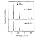
- 6 is an X-ray diffraction pattern of samples obtained in Example 6 and Comparative Example 5.
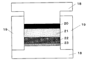
- FIG. It is drawing which shows the outline of a structure of an all-solid-state lithium ion secondary battery. It is drawing which shows the charging / discharging characteristic of the all-solid-state lithium ion secondary battery which uses the sample obtained in Example 6 and Comparative Example 5 as a positive electrode active material.
- Lithium sulfide Li 2 S
- AB acetylene black
- the current-carrying part including the graphite mold and electrode part is housed in a vacuum chamber, and the chamber is filled with high-purity argon gas (oxygen concentration: about 0.2 ppm) to atmospheric pressure after vacuum (about 20 Pa) deaeration. did.
- a pulse current of about 900 A (pulse width 2.5 milliseconds, period 28.6 Hz) was applied while pressurizing the raw material filled in the graphite mold at about 30 MPa.
- the vicinity of the graphite mold was heated at a temperature increase rate of about 200 ° C./min, and reached 900 ° C. 4 minutes and 30 seconds after the start of pulse current application.
- the current application and pressurization were stopped and the mixture was naturally cooled.
- the graphite jig was transferred to a glove box in an argon gas atmosphere at a dew point of ⁇ 68 ° C., and a composite of lithium sulfide and acetylene black was taken out from the mold. Samples were all crushed in the glove box.
- the X-ray diffraction pattern of the obtained composite is shown in FIG. As shown in FIG. 2 (a), peaks derived from Li 2 S and carbon were observed, and it was confirmed to be composed of Li 2 S and carbon. Since the weight change before and after the electric current sintering process is about 4%, the weight ratio between the two is considered to be kept at the charged ratio.
- the composite obtained by the above method is used as a positive electrode active material of a lithium ion secondary battery, lithium metal as a negative electrode, aluminum mesh as a current collector, and LiPF 6 as an electrolytic solution mixed with ethylene carbonate / dimethyl carbonate.
- a charge / discharge test was performed by starting charging by constant current measurement at a cutoff of 1.0 to 3.0 V at a current density of 46.7 mA / g.
- the charge / discharge characteristics are as shown in FIG. 3A, the initial charge capacity is about 140 mAh / g, the initial discharge capacity is about 50 mAh / g, and the raw material mixture before current sintering measured in Comparative Example 1 described later. Compared to the values obtained when the positive electrode material is used as the positive electrode material (FIG. 3B, initial charge capacity 0.2 mAh / g, initial discharge capacity 14 mAh / g).
- Comparative Example 1 In the same manner as in Example 1, 0.4 g of lithium sulfide (Li 2 S) (average particle size 16 ⁇ m) and 0.2 g of acetylene black (AB) (specific surface area 68 m 2 / g) (lithium sulfide: acetylene black (weight ratio)) 2: 1) was weighed in a glove box in an argon gas atmosphere, sealed in a zirconia pot, and mixed in a planetary ball mill for about 30 minutes.
- Li 2 S lithium sulfide
- AB acetylene black
- FIG. 2 (b) shows an X-ray diffraction pattern measured for the mixture as it is without conducting current sintering. As shown in FIG. 2B, peaks derived from Li 2 S and carbon are observed.
- Example 2 the tap density of this mixture was measured in the same manner as in Example 1. As a result, it was 0.37 g / cm 3 , and it was confirmed that it was a low-density mixture as compared with the composite obtained in Example 1. It was.
- Example 2 Further, a charge / discharge test was conducted in the same manner as in Example 1 except that this mixture was used as the positive electrode active material.
- the charge / discharge characteristics are as shown in FIG. 3B, the initial charge capacity is about 0.2 mAh / g, the initial discharge capacity is about 14 mAh / g, and the composite obtained in Example 1 is used as the positive electrode active material. Compared with the case where it does, both initial charge capacity and initial discharge capacity were very low, and it turned out that carbon cannot be joined firmly only by stirring with a planetary ball mill, and the utilization factor of an active material cannot be improved.
- the X-ray diffraction pattern of the obtained composite is shown in FIG. As apparent from this X-ray diffraction pattern, peaks derived from Li 2 S and carbon were observed, and it was found that the obtained composite was composed of Li 2 S and carbon. Since the weight change before and after the electric current sintering process is about 4%, the weight ratio between the two is considered to be kept at the charged ratio.
- the tap density measured in the same manner as in Example 1 was 0.53 g / cm 3 , which was compared with the tap density (0.35 g / cm 3 ) of the raw material mixture before electric sintering measured in Comparative Example 2 described later. Thus, it was confirmed that lithium sulfide and carbon were joined and the density was increased.
- Example 2 Further, a charge / discharge test was conducted in the same manner as in Example 1 using the composite obtained by the above method as a positive electrode active material of a lithium ion secondary battery.
- the charge / discharge characteristics are as shown in FIG. 5A, the initial charge capacity is about 350 mAh / g, the initial discharge capacity is about 130 mAh / g, and the raw material mixture before current sintering measured in Comparative Example 2 described later.
- FIG. 5B initial charge capacity 0.6 mAh / g, initial discharge capacity 27 mAh / g
- Comparative Example 2 In the same manner as in Example 2, 0.2 g of lithium sulfide (Li 2 S) (average particle size 16 ⁇ m) and 0.2 g of acetylene black (AB) (specific surface area 68 m 2 / g) (lithium sulfide: acetylene black (weight ratio)) 1: 1) was weighed in a glove box in an argon gas atmosphere, sealed in a zirconia pot, and thoroughly mixed with a planetary ball mill.
- Li 2 S lithium sulfide
- AB acetylene black
- FIG. 4 (b) shows an X-ray diffraction pattern measured for this mixture as it is without conducting current sintering. As shown in FIG. 4B, peaks derived from Li 2 S and carbon are observed.
- Example 2 Further, the tap density of this mixture was measured in the same manner as in Example 1. As a result, it was 0.35 g / cm 3 , and it was confirmed that it was a low-density mixture as compared with the composite obtained in Example 2. It was.
- Example 2 Further, a charge / discharge test was conducted in the same manner as in Example 1 except that this mixture was used as the positive electrode material.
- the charge / discharge characteristics are as shown in FIG. 5B, the initial charge capacity is about 0.6 mAh / g, the initial discharge capacity is about 27 mAh / g, and the composite obtained in Example 2 is used as the positive electrode active material. Compared with the case where it does, both initial charge capacity and initial discharge capacity were very low, and it turned out that carbon cannot be joined firmly only by stirring with a planetary ball mill, and the utilization factor of an active material cannot be improved.
- the X-ray diffraction pattern of the obtained composite is shown in FIG. As apparent from this X-ray diffraction pattern, peaks derived from Li 2 S and carbon were observed, and it was found that the obtained composite was composed of Li 2 S and carbon. Since the weight change before and after the electric current sintering process is about 4%, the weight ratio between the two is considered to be kept at the charged ratio.
- the tap density measured in the same manner as in Example 1 is 0.40 g / cm 3 , which is higher than the tap density (0.32 g / cm 3 ) of the raw material mixture before current sintering measured in Comparative Example 3 described later.
- the values indicate that lithium sulfide and carbon are joined and densification is progressing.
- Example 2 Further, a charge / discharge test was conducted in the same manner as in Example 1 using the composite obtained by the above method as a positive electrode active material of a lithium ion secondary battery.
- the charge / discharge characteristics are as shown in FIG. 7A, the initial charge capacity is about 270 mAh / g, the initial discharge capacity is about 120 mAh / g, and the raw material mixture before current sintering measured in Comparative Example 3 described later is used.
- FIG. 7B initial charge capacity 1 mAh / g, initial discharge capacity 40 mAh / g
- Comparative Example 3 In the same manner as in Example 3, 0.1 g of lithium sulfide (Li 2 S) (average particle size 16 ⁇ m) and 0.2 g of acetylene black (AB) (specific surface area 68 m 2 / g) (lithium sulfide: acetylene black (weight ratio)) 1: 2) was weighed in a glove box in an argon gas atmosphere, sealed in a zirconia pot, and thoroughly mixed with a planetary ball mill.
- Li 2 S lithium sulfide
- AB acetylene black
- FIG. 6B shows an X-ray diffraction pattern measured for the mixture as it is without performing electric current sintering. As shown in FIG. 6B, peaks derived from Li 2 S and carbon are observed.
- Example 3 the tap density of this mixture was measured in the same manner as in Example 1. As a result, it was 0.32 g / cm 3 , and it was confirmed that it was a low-density mixture as compared with the composite obtained in Example 3. It was.
- Example 2 Further, a charge / discharge test was conducted in the same manner as in Example 1 except that this mixture was used as the positive electrode active material.
- the charge / discharge characteristics are as shown in FIG. 7B, the initial charge capacity is about 1 mAh / g, the initial discharge capacity is about 40 mAh / g, and the composite obtained in Example 3 is used as the positive electrode active material.
- the initial charge capacity and the initial discharge capacity were both very low, and it was found that carbon could not be joined firmly only by stirring with a planetary ball mill, and the utilization rate of the active material could not be improved.
- a lithium sulfide-carbon composite was produced in the same manner as in Example 1 except that the treatment temperature by the electric current sintering method was 1200 ° C.
- the X-ray diffraction pattern of the obtained composite is shown in FIG. As apparent from the X-ray diffraction pattern, peaks derived from Li 2 S and carbon were observed, and it was found that the obtained composite was composed of Li 2 S and carbon. Since the weight change before and after the electric current sintering process is about 3%, the weight ratio between the two is considered to be kept at the charged ratio.
- the tap density measured in the same manner as in Example 1 is 0.57 g / cm 3, which is compared with the tap density (0.40 g / cm 3 ) of the raw material mixture before electric sintering measured in Comparative Example 4 described later. Thus, it was confirmed that lithium sulfide and carbon were joined and the density was increased.
- Example 2 Further, in the same manner as in Example 1 except that the composite obtained by the above method was used as the positive electrode active material of the lithium ion secondary battery and the electrolyte was changed to 1M LiTFSI / TEGDME (tetraethylene glycol dimethyl ether). A discharge test was conducted. The charge / discharge characteristics are as shown in Fig. 9 (g), the initial charge capacity is about 630mAh / g, the initial discharge capacity is about 260mAh / g, and the discharge capacity after 10 cycles is about 170mAh / g. Values when the raw material mixture before current sintering measured in Example 4 was used as the positive electrode active material (FIG. 9 (i), initial charge capacity 0.9 mAh / g, initial discharge capacity 98 mAh / g, discharge capacity 6 cycles after 10 cycles) / g) was significantly improved.
- a lithium sulfide-carbon composite was produced in the same manner as in Example 4 except that the treatment temperature by the electric current sintering method was set to 1000 ° C.
- the X-ray diffraction pattern of the obtained composite is shown in FIG. As apparent from the X-ray diffraction pattern, peaks derived from Li 2 S and carbon were observed, and it was found that the obtained composite was composed of Li 2 S and carbon. Since the weight change before and after the electric current sintering process is about 3%, the weight ratio between the two is considered to be kept at the charged ratio.
- the tap density measured in the same manner as in Example 4 is 0.61 g / cm 3
- a tap density of the raw material mixture prior to electric current sintering was measured in Comparative Example 4 to be described later (0.40g / cm 3) Comparative Thus, it was confirmed that lithium sulfide and carbon were joined and the density was increased.
- Example 4 Further, a charge / discharge test was conducted in the same manner as in Example 4 using the composite obtained by the above method as a positive electrode active material of a lithium ion secondary battery.
- the charge / discharge characteristics are as shown in FIG. 9 (h), the initial charge capacity is about 1170mAh / g, the initial discharge capacity is about 280mAh / g, and the discharge capacity after 10 cycles is about 170mAh / g. Values when the raw material mixture before current sintering measured in Example 4 was used as the positive electrode active material (FIG. 9 (i), initial charge capacity 0.9 mAh / g, initial discharge capacity 98 mAh / g, discharge capacity 6 cycles after 10 cycles) / g) was significantly improved.
- Li 2 S lithium sulfide
- AB acetylene black
- FIG. 8 (i) shows an X-ray diffraction pattern measured for the mixture as it is without conducting current sintering. As shown in FIG. 8 (i), peaks derived from Li 2 S and carbon are observed.
- Example 4 and Example 5 the tap density of this mixture was measured in the same manner as in Example 4 and Example 5. As a result, it was 0.40 g / cm 3. Compared with the composites obtained in Example 4 and Example 5, the density was low. It was confirmed that the mixture was.
- Example 9 (i) a charge / discharge test was conducted in the same manner as in Example 4 and Example 5 except that this mixture was used as the positive electrode material.
- the charge / discharge characteristics are as shown in FIG. 9 (i).
- the initial charge capacity is about 0.9 mAh / g
- the initial discharge capacity is about 98 mAh / g
- the discharge capacity after 10 cycles is 6 mAh / g.
- the initial charge capacity, the initial discharge capacity, and the discharge capacity after 10 cycles are all very low. It turned out that it cannot join firmly and cannot improve the utilization factor of an active material.
- Li 2 S lithium sulfide
- AB acetylene black
- the X-ray diffraction pattern of the obtained composite is shown in FIG. As apparent from the X-ray diffraction pattern, peaks derived from Li 2 S and carbon were observed, and it was found that the obtained composite was composed of Li 2 S and carbon. Since the weight change before and after the electric current sintering process is about 3%, the weight ratio between the two is considered to be kept at the charged ratio.
- the tap density measured in the same manner as in Example 1 is 0.54 g / cm 3, which is compared with the tap density (0.35 g / cm 3 ) of the raw material mixture before electric sintering measured in Comparative Example 5 described later. Thus, it was confirmed that lithium sulfide and carbon were joined and densification was progressing.
- the composite obtained by the above method was used as a positive electrode active material of a lithium ion secondary battery, and an all solid lithium ion secondary battery was produced using a lithium ion conductive solid electrolyte.
- the configuration of the battery is as shown in FIG. 11, in which a negative electrode, an electrolyte, a positive electrode, and a current collector are stacked in a PET tube, and the upper and lower sides are sandwiched between metal punches.
- the charge / discharge characteristics are as shown in FIG. 12 (j).
- the initial charge capacity is about 230 mAh / g
- the initial discharge capacity is about 190 mAh / g
- the discharge capacity after 10 cycles is about 150 mAh / g.
- the charge / discharge efficiency in the initial cycle was about 85%, which was remarkably improved as compared with the case where the electrolytic solution was used (for example, about 20 to 45% in Examples 1 to 5). This is considered to be because the elution of the sulfur component at the time of charging that can occur when the electrolytic solution is used can be suppressed.
- Li 2 S lithium sulfide
- AB acetylene black
- FIG. 10 (k) shows an X-ray diffraction pattern measured for the mixture as it is without conducting current sintering. As shown in the figure, peaks derived from Li 2 S and carbon are observed.
- Example 6 the tap density of this mixture was measured in the same manner as in Example 6. As a result, it was 0.35 g / cm 3 , and it was confirmed that it was a low-density mixture as compared with the composite obtained in Example 6. It was.
Landscapes
- Chemical & Material Sciences (AREA)
- Chemical Kinetics & Catalysis (AREA)
- Electrochemistry (AREA)
- General Chemical & Material Sciences (AREA)
- Engineering & Computer Science (AREA)
- Inorganic Chemistry (AREA)
- Materials Engineering (AREA)
- Manufacturing & Machinery (AREA)
- Organic Chemistry (AREA)
- Battery Electrode And Active Subsutance (AREA)
- Secondary Cells (AREA)
- Carbon And Carbon Compounds (AREA)
Abstract
Description
1. 硫化リチウムと炭素材料とが接合してなる複合体であって、炭素含有量が15~70質量%であり、タップ密度が、炭素含有量が30質量%以上の場合に0.4g/cm3以上であり、炭素含有量が30質量%未満の場合に0.5 g/cm3以上であることを特徴とする硫化リチウム-炭素複合体。
2. 非酸化性雰囲気下において硫化リチウムと比表面積60m2/g以上の炭素材料の混合物を導電性を有する型に充填し、非酸化性雰囲気下において該混合物を加圧した状態で直流パルス電流を通電して、硫化リチウムと炭素材料を加熱反応させることを特徴とする上記項1に記載の硫化リチウム-炭素複合体の製造方法。
3. 炭素材料がアセチレンブラックであって、炭素材料の使用量が、硫化リチウムと炭素材料の合計量を基準として、15~70質量%である上記項2に記載の方法。
4. 10MPa以上の加圧下において、700~1400℃で反応させる上記項2又は3に記載の方法。
5. 上記項1に記載の硫化リチウム-炭素複合体を含むリチウムイオン二次電池用正極活物質。
6. 上記項5に記載の正極活物質を構成要素とするリチウムイオン二次電池。
7. 上記項5に記載の正極活物質とリチウムイオン伝導性固体電解質を構成要素として含む全固体リチウムイオン二次電池。
8. リチウムイオン伝導性固体電解質が、硫黄を構成元素とする無機化合物を含む固体電解質である上記項7に記載の全固体リチウムイオン二次電池。
本発明では、出発原料としては、硫化リチウムと炭素材料を用いる。
本発明の硫化リチウム-炭素複合体の製造方法では、まず、非酸化性雰囲気下において、硫化リチウムと炭素材料からなる出発原料を十分に混合した後、導電性を有する型に充填し、更に、非酸化性雰囲気下において、該混合物を加圧した状態で、放電プラズマ焼結法、パルス通電焼結法、プラズマ活性化焼結法等と呼ばれる直流パルス電流を通電する通電焼結法によって原料混合物を焼結させる。これによって、目的とする高密度の硫化リチウム-炭素複合体を得ることができる。
上記した方法によって得られる硫化リチウムと炭素の複合体は、原料とする硫化リチウムと炭素の粒子同士が強固に接合されて高密度化されたものであり、良好な導電ネットワークが形成されている。このため、リチウム二次電池正極用活物質として用いる場合に、電子伝導性が向上して、高容量の正極活物質として優れた性能を発揮できる。
硫化リチウム(Li2S)(平均粒径16μm)0.4gとアセチレンブラック(AB)(比表面積68m2/g)0.2g(硫化リチウム:アセチレンブラック(重量比)=2:1)をアルゴンガス雰囲気のグローブボックス内(露点-68℃)で秤量し、ジルコニアポットに封入して遊星ボールミルで約30分間混合し、グローブボックス内において内径15mmの黒鉛型材に充填した。
実施例1と同様にして、硫化リチウム(Li2S)(平均粒径16μm)0.4gとアセチレンブラック(AB)(比表面積68m2/g)0.2g(硫化リチウム:アセチレンブラック(重量比)=2:1)をアルゴンガス雰囲気のグローブボックス内で秤量し、ジルコニアポットに封入して遊星ボールミルで約30分間混合した。
硫化リチウム(Li2S)(平均粒径16μm)0.2gとアセチレンブラック(AB)(比表面積68m2/g)0.2g(硫化リチウム:アセチレンブラック(重量比)=1:1)を原料として用いること以外は、実施例1と同様にして、硫化リチウム-炭素複合体を作製した。
実施例2と同様にして、硫化リチウム(Li2S)(平均粒径16μm)0.2gとアセチレンブラック(AB)(比表面積68m2/g)0.2g(硫化リチウム:アセチレンブラック(重量比)=1:1)をアルゴンガス雰囲気のグローブボックス内で秤量し、ジルコニアポットに封入して遊星ボールミルで十分に混合した。
硫化リチウム(Li2S)(平均粒径16μm)0.1gとアセチレンブラック(AB)(比表面積68m2/g)0.2g(硫化リチウム:アセチレンブラック(重量比)=1:2)を原料として用いること以外は、実施例1と同様にして、硫化リチウム-炭素複合体を作製した。
実施例3と同様にして、硫化リチウム(Li2S)(平均粒径16μm)0.1gとアセチレンブラック(AB)(比表面積68m2/g)0.2g(硫化リチウム:アセチレンブラック(重量比)=1:2)をアルゴンガス雰囲気のグローブボックス内で秤量し、ジルコニアポットに封入して遊星ボールミルで十分に混合した。
硫化リチウム(Li2S)(平均粒径16μm)0.4gとアセチレンブラック(AB)(比表面積68m2/g)0.1g(硫化リチウム:アセチレンブラック(重量比)=4:1)を原料として用い、通電焼結法による処理温度を1200℃にすること以外は、実施例1と同様にして、硫化リチウム-炭素複合体を作製した。
硫化リチウム(Li2S)(平均粒径16μm)0.4gとアセチレンブラック(AB)(比表面積68m2/g)0.1g(硫化リチウム:アセチレンブラック(重量比)=4:1)を原料として用い、通電焼結法による処理温度を1000℃にすること以外は、実施例4と同様にして、硫化リチウム-炭素複合体を作製した。
実施例4および実施例5と同様にして、硫化リチウム(Li2S)(平均粒径16μm)0.4gとアセチレンブラック(AB)(比表面積68m2/g)0.1g(硫化リチウム:アセチレンブラック(重量比)=4:1)をアルゴンガス雰囲気のグローブボックス内で秤量し、ジルコニアポットに封入して遊星ボールミルで十分に混合した。
硫化リチウム(Li2S)(平均粒径16μm)0.2gとアセチレンブラック(AB)(比表面積68m2/g)0.2g(硫化リチウム:アセチレンブラック(重量比)=1:1)を原料として用い、通電焼結法による処理温度を1000℃にすること以外は、実施例1と同様にして、硫化リチウム-炭素複合体を作製した。
実施例6と同様にして、硫化リチウム(Li2S)(平均粒径16μm)0.2gとアセチレンブラック(AB)(比表面積68m2/g)0.2g(硫化リチウム:アセチレンブラック(重量比)=1:1)をアルゴンガス雰囲気のグローブボックス内で秤量し、ジルコニアポットに封入して遊星ボールミルで十分に混合した。
2 試料
3 ダイ(導電性容器)
4、5 パンチ
6,7 パンチ電極
8 水冷真空チャンバー
9 冷却水路
10、16 水冷却機構
11 焼結用電源
12 制御装置
13 加圧機構
14 位置計測機構
15 雰囲気制御機構
17 温度計測装置
18 金属パンチ
19 PET管
20 負極
21 リチウムイオン伝導性固体電解質
22 正極
23 集電体
Claims (8)
- 硫化リチウムと炭素材料とが接合してなる複合体であって、炭素含有量が15~70質量%であり、タップ密度が、炭素含有量が30質量%以上の場合に0.4g/cm3以上であり、炭素含有量が30質量%未満の場合に0.5 g/cm3以上であることを特徴とする硫化リチウム-炭素複合体。
- 非酸化性雰囲気下において硫化リチウムと比表面積60m2/g以上の炭素材料の混合物を導電性を有する型に充填し、非酸化性雰囲気下において該混合物を加圧した状態で直流パルス電流を通電して、硫化リチウムと炭素材料を加熱反応させることを特徴とする請求項1に記載の硫化リチウム-炭素複合体の製造方法。
- 炭素材料がアセチレンブラックであって、炭素材料の使用量が、硫化リチウムと炭素材料の合計量を基準として、15~70質量%である請求項2に記載の方法。
- 10MPa以上の加圧下において、700~1400℃で反応させる請求項2又は3に記載の方法。
- 請求項1に記載の硫化リチウム-炭素複合体を含むリチウムイオン二次電池用正極活物質。
- 請求項5に記載の正極活物質を構成要素とするリチウムイオン二次電池。
- 請求項5に記載の正極活物質とリチウムイオン伝導性固体電解質を構成要素として含む全固体リチウムイオン二次電池。
- リチウムイオン伝導性固体電解質が、硫黄を構成元素とする無機化合物を含む固体電解質である請求項7に記載の全固体リチウムイオン二次電池。
Priority Applications (2)
| Application Number | Priority Date | Filing Date | Title |
|---|---|---|---|
| US13/120,237 US9337476B2 (en) | 2008-09-24 | 2009-08-24 | Lithium sulfide-carbon complex, process for producing the complex, and lithium ion secondary battery utilizing the complex |
| JP2010530784A JP5419020B2 (ja) | 2008-09-24 | 2009-08-24 | 硫化リチウム−炭素複合体、その製造方法、及び該複合体を用いるリチウムイオン二次電池 |
Applications Claiming Priority (4)
| Application Number | Priority Date | Filing Date | Title |
|---|---|---|---|
| JP2008243679 | 2008-09-24 | ||
| JP2008-243679 | 2008-09-24 | ||
| JP2009123686 | 2009-05-22 | ||
| JP2009-123686 | 2009-05-22 |
Publications (1)
| Publication Number | Publication Date |
|---|---|
| WO2010035602A1 true WO2010035602A1 (ja) | 2010-04-01 |
Family
ID=42059609
Family Applications (1)
| Application Number | Title | Priority Date | Filing Date |
|---|---|---|---|
| PCT/JP2009/064721 Ceased WO2010035602A1 (ja) | 2008-09-24 | 2009-08-24 | 硫化リチウム-炭素複合体、その製造方法、及び該複合体を用いるリチウムイオン二次電池 |
Country Status (3)
| Country | Link |
|---|---|
| US (1) | US9337476B2 (ja) |
| JP (1) | JP5419020B2 (ja) |
| WO (1) | WO2010035602A1 (ja) |
Cited By (19)
| Publication number | Priority date | Publication date | Assignee | Title |
|---|---|---|---|---|
| JP2012069305A (ja) * | 2010-09-22 | 2012-04-05 | Hitachi Zosen Corp | 全固体二次電池の製造方法 |
| US20120115039A1 (en) * | 2010-04-23 | 2012-05-10 | Murata Manufacturing Co., Ltd. | All Solid Secondary Battery and Manufacturing Method Therefor |
| WO2012102037A1 (ja) * | 2011-01-27 | 2012-08-02 | 出光興産株式会社 | アルカリ金属硫化物と導電剤の複合材料 |
| JP2012160415A (ja) * | 2011-02-03 | 2012-08-23 | Idemitsu Kosan Co Ltd | 二次電池用電極材料、電極及び二次電池 |
| WO2012171888A3 (de) * | 2011-06-14 | 2013-05-30 | Chemetall Gmbh | Verfahren zur herstellung eines kohlenstoffbeschichteten lithiumsulfids und dessen verwendung |
| JP2013164942A (ja) * | 2012-02-10 | 2013-08-22 | Hitachi Zosen Corp | 被覆正極活物質、および該被覆正極活物質を用いてなる全固体リチウム二次電池 |
| JP2013214421A (ja) * | 2012-04-02 | 2013-10-17 | National Institute Of Advanced Industrial & Technology | 炭素−固体電解質複合体およびその製造方法 |
| JP2013229227A (ja) * | 2012-04-26 | 2013-11-07 | Furukawa Co Ltd | 二次電池用正極材料の製造方法および二次電池用正極材料、並びにそれを用いた二次電池用正極および二次電池 |
| US20130337347A1 (en) * | 2012-06-18 | 2013-12-19 | Uchicago Argonne, Llc | Ultrasound assisted in-situ formation of carbon/sulfur cathodes |
| KR20140042854A (ko) * | 2011-06-14 | 2014-04-07 | 록우드 리튬 게엠베하 | 탄소-코팅된 리튬 설파이드를 생산하는 방법 및 이의 용도 |
| WO2014112401A1 (ja) * | 2013-01-18 | 2014-07-24 | ソニー株式会社 | 電極用複合材料及びその製造方法並びに二次電池 |
| WO2014162693A1 (ja) * | 2013-04-02 | 2014-10-09 | 出光興産株式会社 | 複合材料 |
| CN104205429A (zh) * | 2011-11-09 | 2014-12-10 | 罗克伍德锂有限责任公司 | 涂覆Li2S@C的锂金属产品及其制备方法和应用 |
| CN106531976A (zh) * | 2015-09-11 | 2017-03-22 | 中国科学院苏州纳米技术与纳米仿生研究所 | 多层结构硫化锂/碳电极材料及其制备方法与应用 |
| JP2017222567A (ja) * | 2016-06-14 | 2017-12-21 | 出光興産株式会社 | 硫化リチウム、及びその製造方法 |
| JP2018523280A (ja) * | 2015-08-13 | 2018-08-16 | ザ リージェンツ オブ ザ ユニバーシティ オブ カリフォルニア | 硫化リチウム電極および方法 |
| JP2020064740A (ja) * | 2018-10-16 | 2020-04-23 | トヨタ自動車株式会社 | 硫化物全固体電池 |
| CN113991073A (zh) * | 2021-09-27 | 2022-01-28 | 杭州电子科技大学 | 一种硫化锂电极材料的制备方法 |
| CN114188509A (zh) * | 2021-12-01 | 2022-03-15 | 杭州电子科技大学 | 一种基于碳纳米管封装手段的硫化锂电极的制备方法 |
Families Citing this family (14)
| Publication number | Priority date | Publication date | Assignee | Title |
|---|---|---|---|---|
| WO2011102054A1 (ja) * | 2010-02-18 | 2011-08-25 | 株式会社 村田製作所 | 全固体二次電池用電極活物質および全固体二次電池 |
| KR101256065B1 (ko) | 2011-06-02 | 2013-04-18 | 로베르트 보쉬 게엠베하 | 리튬 이차 전지용 양극 및 이를 포함하는 리튬 이차 전지 |
| JP6203474B2 (ja) * | 2011-11-24 | 2017-09-27 | 出光興産株式会社 | 電極材料、電極及びそれを用いたリチウムイオン電池 |
| WO2013136524A1 (ja) * | 2012-03-16 | 2013-09-19 | 株式会社 東芝 | リチウムイオン伝導性硫化物、固体電解質二次電池および電池パック |
| KR20140076161A (ko) * | 2012-12-12 | 2014-06-20 | 현대자동차주식회사 | 리튬유황 이차전지 양극용 분말구조체와 그 제조 방법 |
| DE102013111853A1 (de) * | 2013-10-28 | 2015-04-30 | Rockwood Lithium GmbH | Kohlenstoffbeschichtetes Lithiumsulfid |
| US10734634B2 (en) * | 2014-10-22 | 2020-08-04 | Japan Science And Technology Agency | Positive electrode for all-solid secondary battery, method for manufacturing same, and all-solid secondary battery |
| KR101806604B1 (ko) | 2015-03-13 | 2017-12-07 | 현대자동차주식회사 | 전고체 리튬-황 전지용 양극 활물질의 제조방법 |
| US10840539B2 (en) | 2015-06-22 | 2020-11-17 | King Abdullah University Of Science And Technology | Lithium batteries, anodes, and methods of anode fabrication |
| CN106229491B (zh) * | 2016-09-10 | 2019-01-15 | 华南理工大学 | 一种生物质废弃物热还原活化硫酸锂制备锂硫电池正极Li2S/NCs复合材料的方法 |
| WO2018152807A1 (zh) * | 2017-02-25 | 2018-08-30 | 深圳市玖创科技有限公司 | 一种高效的锂离子电池材料微波烧结设备 |
| CN106684317B (zh) * | 2017-02-25 | 2019-06-11 | 内蒙古恒胜新能源科技有限公司 | 一种高效的锂离子电池材料微波烧结设备 |
| WO2019178533A1 (en) * | 2018-03-16 | 2019-09-19 | University Of Maryland, College Park | All solid-state sodium-sulfur or lithium-sulfur battery prepared using cast-annealing method |
| US20250239599A1 (en) * | 2024-01-22 | 2025-07-24 | Lg Energy Solution, Ltd. | Composite cathode for all-solid-state battery, methods for making, and an all-solid-state battery thereof |
Citations (6)
| Publication number | Priority date | Publication date | Assignee | Title |
|---|---|---|---|---|
| JP2005011696A (ja) * | 2003-06-19 | 2005-01-13 | Matsushita Electric Ind Co Ltd | 非水電解質二次電池用負極材料 |
| JP2005259629A (ja) * | 2004-03-15 | 2005-09-22 | Sanyo Electric Co Ltd | 非水電解質電池用正極及びその製造方法、並びに、この正極を用いた電池及びその製造方法 |
| JP2006164779A (ja) * | 2004-12-08 | 2006-06-22 | Sanyo Electric Co Ltd | 正極材料、非水電解質二次電池および正極材料の製造方法 |
| JP2008257962A (ja) * | 2007-04-03 | 2008-10-23 | Murata Mfg Co Ltd | 全固体リチウム二次電池 |
| JP2009009905A (ja) * | 2007-06-29 | 2009-01-15 | Sumitomo Electric Ind Ltd | 薄膜リチウム二次電池およびその製造方法 |
| JP2009064667A (ja) * | 2007-09-06 | 2009-03-26 | Research Institute Of Innovative Technology For The Earth | 全固体薄膜電池、その製造方法およびその製造装置 |
Family Cites Families (5)
| Publication number | Priority date | Publication date | Assignee | Title |
|---|---|---|---|---|
| JPH06275313A (ja) | 1993-03-22 | 1994-09-30 | Matsushita Electric Ind Co Ltd | リチウム電池 |
| JP3489960B2 (ja) * | 1997-04-01 | 2004-01-26 | 松下電器産業株式会社 | アルカリ蓄電池 |
| JP2948205B1 (ja) * | 1998-05-25 | 1999-09-13 | 花王株式会社 | 二次電池用負極の製造方法 |
| KR101099225B1 (ko) * | 2004-02-13 | 2011-12-27 | 산요덴키가부시키가이샤 | 비수성 전해질 2차 전지용 양극 및 그의 제조 방법 및비수성 전해질 2차 전지 및 그의 제조 방법 |
| JP4693371B2 (ja) * | 2004-07-16 | 2011-06-01 | 三洋電機株式会社 | 非水電解質二次電池 |
-
2009
- 2009-08-24 US US13/120,237 patent/US9337476B2/en not_active Expired - Fee Related
- 2009-08-24 WO PCT/JP2009/064721 patent/WO2010035602A1/ja not_active Ceased
- 2009-08-24 JP JP2010530784A patent/JP5419020B2/ja not_active Expired - Fee Related
Patent Citations (6)
| Publication number | Priority date | Publication date | Assignee | Title |
|---|---|---|---|---|
| JP2005011696A (ja) * | 2003-06-19 | 2005-01-13 | Matsushita Electric Ind Co Ltd | 非水電解質二次電池用負極材料 |
| JP2005259629A (ja) * | 2004-03-15 | 2005-09-22 | Sanyo Electric Co Ltd | 非水電解質電池用正極及びその製造方法、並びに、この正極を用いた電池及びその製造方法 |
| JP2006164779A (ja) * | 2004-12-08 | 2006-06-22 | Sanyo Electric Co Ltd | 正極材料、非水電解質二次電池および正極材料の製造方法 |
| JP2008257962A (ja) * | 2007-04-03 | 2008-10-23 | Murata Mfg Co Ltd | 全固体リチウム二次電池 |
| JP2009009905A (ja) * | 2007-06-29 | 2009-01-15 | Sumitomo Electric Ind Ltd | 薄膜リチウム二次電池およびその製造方法 |
| JP2009064667A (ja) * | 2007-09-06 | 2009-03-26 | Research Institute Of Innovative Technology For The Earth | 全固体薄膜電池、その製造方法およびその製造装置 |
Cited By (39)
| Publication number | Priority date | Publication date | Assignee | Title |
|---|---|---|---|---|
| US20120115039A1 (en) * | 2010-04-23 | 2012-05-10 | Murata Manufacturing Co., Ltd. | All Solid Secondary Battery and Manufacturing Method Therefor |
| CN102473960A (zh) * | 2010-04-23 | 2012-05-23 | 株式会社村田制作所 | 全固体二次电池及其制造方法 |
| JP2012069305A (ja) * | 2010-09-22 | 2012-04-05 | Hitachi Zosen Corp | 全固体二次電池の製造方法 |
| CN103329319A (zh) * | 2011-01-27 | 2013-09-25 | 出光兴产株式会社 | 碱金属硫化物和导电剂的复合材料 |
| WO2012102037A1 (ja) * | 2011-01-27 | 2012-08-02 | 出光興産株式会社 | アルカリ金属硫化物と導電剤の複合材料 |
| JPWO2012102037A1 (ja) * | 2011-01-27 | 2014-06-30 | 出光興産株式会社 | アルカリ金属硫化物と導電剤の複合材料 |
| JP2012160415A (ja) * | 2011-02-03 | 2012-08-23 | Idemitsu Kosan Co Ltd | 二次電池用電極材料、電極及び二次電池 |
| WO2012171888A3 (de) * | 2011-06-14 | 2013-05-30 | Chemetall Gmbh | Verfahren zur herstellung eines kohlenstoffbeschichteten lithiumsulfids und dessen verwendung |
| US20140124708A1 (en) * | 2011-06-14 | 2014-05-08 | Chemetall Gmbh | Method for producing a carbon-coated lithium sulfide and use thereof |
| US9147883B2 (en) * | 2011-06-14 | 2015-09-29 | Rockwood Lithium GmbH | Method for producing a carbon-coated lithium sulfide and use thereof |
| US9023252B2 (en) | 2011-06-14 | 2015-05-05 | Rockwood Lithium GmbH | Method for producing a carbon-coated lithium sulfide and use thereof |
| KR20140042854A (ko) * | 2011-06-14 | 2014-04-07 | 록우드 리튬 게엠베하 | 탄소-코팅된 리튬 설파이드를 생산하는 방법 및 이의 용도 |
| US20140110635A1 (en) * | 2011-06-14 | 2014-04-24 | Ulrich Wietelmann | Method for producing a carbon-coated lithium sulfide and use thereof |
| CN103764566A (zh) * | 2011-06-14 | 2014-04-30 | 罗克伍德锂有限责任公司 | 碳涂覆的硫化锂的制备方法及其应用 |
| JP2014522373A (ja) * | 2011-06-14 | 2014-09-04 | ロックウッド リチウム ゲゼルシャフト ミット ベシュレンクテル ハフツング | 炭素被覆硫化リチウムの製造方法およびその使用 |
| KR101948769B1 (ko) * | 2011-06-14 | 2019-02-15 | 알베마를 저머니 게엠베하 | 탄소-코팅된 리튬 설파이드를 생산하는 방법 및 이의 용도 |
| CN104205429B (zh) * | 2011-11-09 | 2018-08-10 | 罗克伍德锂有限责任公司 | 涂覆Li2S@C的锂金属产品及其制备方法和应用 |
| CN104205429A (zh) * | 2011-11-09 | 2014-12-10 | 罗克伍德锂有限责任公司 | 涂覆Li2S@C的锂金属产品及其制备方法和应用 |
| JP2013164942A (ja) * | 2012-02-10 | 2013-08-22 | Hitachi Zosen Corp | 被覆正極活物質、および該被覆正極活物質を用いてなる全固体リチウム二次電池 |
| JP2013214421A (ja) * | 2012-04-02 | 2013-10-17 | National Institute Of Advanced Industrial & Technology | 炭素−固体電解質複合体およびその製造方法 |
| JP2013229227A (ja) * | 2012-04-26 | 2013-11-07 | Furukawa Co Ltd | 二次電池用正極材料の製造方法および二次電池用正極材料、並びにそれを用いた二次電池用正極および二次電池 |
| US20130337347A1 (en) * | 2012-06-18 | 2013-12-19 | Uchicago Argonne, Llc | Ultrasound assisted in-situ formation of carbon/sulfur cathodes |
| US9748572B2 (en) * | 2012-06-18 | 2017-08-29 | Uchicago Argonne, Llc | Ultrasound assisted in-situ formation of carbon/sulfur cathodes |
| JP2018088420A (ja) * | 2013-01-18 | 2018-06-07 | 株式会社村田製作所 | 電極用複合材料及び二次電池 |
| JPWO2014112401A1 (ja) * | 2013-01-18 | 2017-01-19 | ソニー株式会社 | 電極用複合材料及びその製造方法並びに二次電池 |
| WO2014112401A1 (ja) * | 2013-01-18 | 2014-07-24 | ソニー株式会社 | 電極用複合材料及びその製造方法並びに二次電池 |
| CN105074974A (zh) * | 2013-04-02 | 2015-11-18 | 出光兴产株式会社 | 复合材料 |
| WO2014162693A1 (ja) * | 2013-04-02 | 2014-10-09 | 出光興産株式会社 | 複合材料 |
| JP2018523280A (ja) * | 2015-08-13 | 2018-08-16 | ザ リージェンツ オブ ザ ユニバーシティ オブ カリフォルニア | 硫化リチウム電極および方法 |
| CN106531976B (zh) * | 2015-09-11 | 2019-02-01 | 中国科学院苏州纳米技术与纳米仿生研究所 | 多层结构硫化锂/碳电极材料及其制备方法与应用 |
| CN106531976A (zh) * | 2015-09-11 | 2017-03-22 | 中国科学院苏州纳米技术与纳米仿生研究所 | 多层结构硫化锂/碳电极材料及其制备方法与应用 |
| JP2017222567A (ja) * | 2016-06-14 | 2017-12-21 | 出光興産株式会社 | 硫化リチウム、及びその製造方法 |
| JP7014496B2 (ja) | 2016-06-14 | 2022-02-01 | 出光興産株式会社 | 硫化リチウム、及びその製造方法 |
| JP2020064740A (ja) * | 2018-10-16 | 2020-04-23 | トヨタ自動車株式会社 | 硫化物全固体電池 |
| JP7119884B2 (ja) | 2018-10-16 | 2022-08-17 | トヨタ自動車株式会社 | 硫化物全固体電池 |
| CN113991073A (zh) * | 2021-09-27 | 2022-01-28 | 杭州电子科技大学 | 一种硫化锂电极材料的制备方法 |
| CN113991073B (zh) * | 2021-09-27 | 2023-08-11 | 杭州电子科技大学 | 一种硫化锂电极材料的制备方法 |
| CN114188509A (zh) * | 2021-12-01 | 2022-03-15 | 杭州电子科技大学 | 一种基于碳纳米管封装手段的硫化锂电极的制备方法 |
| CN114188509B (zh) * | 2021-12-01 | 2023-12-01 | 杭州电子科技大学 | 一种基于碳纳米管封装手段的硫化锂电极的制备方法 |
Also Published As
| Publication number | Publication date |
|---|---|
| US9337476B2 (en) | 2016-05-10 |
| JPWO2010035602A1 (ja) | 2012-02-23 |
| JP5419020B2 (ja) | 2014-02-19 |
| US20110171537A1 (en) | 2011-07-14 |
Similar Documents
| Publication | Publication Date | Title |
|---|---|---|
| JP5419020B2 (ja) | 硫化リチウム−炭素複合体、その製造方法、及び該複合体を用いるリチウムイオン二次電池 | |
| JP6021099B2 (ja) | 炭素−固体電解質複合体およびその製造方法 | |
| Yuan et al. | High‐Safety Anode Materials for Advanced Lithium‐Ion Batteries | |
| JP7075760B2 (ja) | ナトリウムイオン二次電池用正極活物質 | |
| CN107078295B (zh) | 全固体二次电池用正极及其制备方法和全固体二次电池 | |
| CN105518913B (zh) | 硫化锂-铁-碳复合体 | |
| Zhang et al. | A high energy density Li 2 S@ C nanocomposite cathode with a nitrogen-doped carbon nanotube top current collector | |
| JP7348600B2 (ja) | ナトリウムイオン二次電池正極活物質、ナトリウムイオン二次電池用正極材料、ナトリウムイオン二次電池用正極、及び、ナトリウムイオン二次電池 | |
| JP7145519B2 (ja) | ハロゲン含有複合体及びその製造方法 | |
| KR20170084271A (ko) | 리튬-철-인-황-탄소 복합체 및 그 제조 방법 | |
| Von Lim et al. | WS 2–3D graphene nano-architecture networks for high performance anode materials of lithium ion batteries | |
| JP6878529B2 (ja) | リチウムイオン伝導性酸化物 | |
| JP2012182115A (ja) | 蓄電デバイス用負極活物質の製造方法 | |
| JP5733805B2 (ja) | 非水電解質二次電池用正極活物質、および非水電解質二次電池用正極活物質の製造方法 | |
| Song et al. | General Prelithiation Approaches and the Corresponding Full Cell Design | |
| JP2011096372A (ja) | リチウムイオン二次電池用電極活物質及びその製造方法 | |
| JP2022157525A (ja) | 固体電解質及びその製造方法、リチウムイオン電池用電極並びにリチウムイオン電池 | |
| JP4997496B2 (ja) | 電極用複合粉末及びその製造方法 | |
| JP5071919B2 (ja) | 高密度アセチレンブラック及びその製造方法 | |
| JP7778420B2 (ja) | 硫化リチウム-鉄-炭素複合体 | |
| KR101400557B1 (ko) | 리튬이온이차전지용 비정질 탄소 복합화 음극재의 제조방법 및 이를 통해 제조된 비정질 탄소 복합화 음극재 | |
| JP7797056B2 (ja) | 鉄含有多硫化リチウム | |
| JP2023180588A (ja) | 固体電極層及びその製造方法 | |
| JP2018106980A (ja) | 非水系二次電池用正極材料、非水系二次電池および非水系二次電池用正極材料の製造方法 | |
| CN120348919A (zh) | 一种小颗粒的磷酸铁锂正极材料及其制备方法、锂离子电池和用电设备 |
Legal Events
| Date | Code | Title | Description |
|---|---|---|---|
| 121 | Ep: the epo has been informed by wipo that ep was designated in this application |
Ref document number: 09816019 Country of ref document: EP Kind code of ref document: A1 |
|
| WWE | Wipo information: entry into national phase |
Ref document number: 2010530784 Country of ref document: JP |
|
| WWE | Wipo information: entry into national phase |
Ref document number: 13120237 Country of ref document: US |
|
| NENP | Non-entry into the national phase |
Ref country code: DE |
|
| 122 | Ep: pct application non-entry in european phase |
Ref document number: 09816019 Country of ref document: EP Kind code of ref document: A1 |