WO2009090899A1 - 載置台装置、処理装置および温度制御方法 - Google Patents
載置台装置、処理装置および温度制御方法 Download PDFInfo
- Publication number
- WO2009090899A1 WO2009090899A1 PCT/JP2009/050058 JP2009050058W WO2009090899A1 WO 2009090899 A1 WO2009090899 A1 WO 2009090899A1 JP 2009050058 W JP2009050058 W JP 2009050058W WO 2009090899 A1 WO2009090899 A1 WO 2009090899A1
- Authority
- WO
- WIPO (PCT)
- Prior art keywords
- temperature
- mounting table
- innermost
- heater
- heating
- Prior art date
- Legal status (The legal status is an assumption and is not a legal conclusion. Google has not performed a legal analysis and makes no representation as to the accuracy of the status listed.)
- Ceased
Links
Images


Classifications
-
- H—ELECTRICITY
- H01—ELECTRIC ELEMENTS
- H01L—SEMICONDUCTOR DEVICES NOT COVERED BY CLASS H10
- H01L21/00—Processes or apparatus adapted for the manufacture or treatment of semiconductor or solid state devices or of parts thereof
- H01L21/67—Apparatus specially adapted for handling semiconductor or electric solid state devices during manufacture or treatment thereof; Apparatus specially adapted for handling wafers during manufacture or treatment of semiconductor or electric solid state devices or components ; Apparatus not specifically provided for elsewhere
- H01L21/67005—Apparatus not specifically provided for elsewhere
- H01L21/67242—Apparatus for monitoring, sorting or marking
- H01L21/67248—Temperature monitoring
-
- C—CHEMISTRY; METALLURGY
- C23—COATING METALLIC MATERIAL; COATING MATERIAL WITH METALLIC MATERIAL; CHEMICAL SURFACE TREATMENT; DIFFUSION TREATMENT OF METALLIC MATERIAL; COATING BY VACUUM EVAPORATION, BY SPUTTERING, BY ION IMPLANTATION OR BY CHEMICAL VAPOUR DEPOSITION, IN GENERAL; INHIBITING CORROSION OF METALLIC MATERIAL OR INCRUSTATION IN GENERAL
- C23C—COATING METALLIC MATERIAL; COATING MATERIAL WITH METALLIC MATERIAL; SURFACE TREATMENT OF METALLIC MATERIAL BY DIFFUSION INTO THE SURFACE, BY CHEMICAL CONVERSION OR SUBSTITUTION; COATING BY VACUUM EVAPORATION, BY SPUTTERING, BY ION IMPLANTATION OR BY CHEMICAL VAPOUR DEPOSITION, IN GENERAL
- C23C16/00—Chemical coating by decomposition of gaseous compounds, without leaving reaction products of surface material in the coating, i.e. chemical vapour deposition [CVD] processes
- C23C16/44—Chemical coating by decomposition of gaseous compounds, without leaving reaction products of surface material in the coating, i.e. chemical vapour deposition [CVD] processes characterised by the method of coating
- C23C16/46—Chemical coating by decomposition of gaseous compounds, without leaving reaction products of surface material in the coating, i.e. chemical vapour deposition [CVD] processes characterised by the method of coating characterised by the method used for heating the substrate
-
- H—ELECTRICITY
- H01—ELECTRIC ELEMENTS
- H01L—SEMICONDUCTOR DEVICES NOT COVERED BY CLASS H10
- H01L21/00—Processes or apparatus adapted for the manufacture or treatment of semiconductor or solid state devices or of parts thereof
- H01L21/67—Apparatus specially adapted for handling semiconductor or electric solid state devices during manufacture or treatment thereof; Apparatus specially adapted for handling wafers during manufacture or treatment of semiconductor or electric solid state devices or components ; Apparatus not specifically provided for elsewhere
- H01L21/67005—Apparatus not specifically provided for elsewhere
- H01L21/67011—Apparatus for manufacture or treatment
- H01L21/67098—Apparatus for thermal treatment
- H01L21/67103—Apparatus for thermal treatment mainly by conduction
Definitions
- the present invention relates to a processing apparatus for performing a heat treatment such as a film forming process on an object to be processed such as a semiconductor wafer, a mounting table apparatus used therefor, and a temperature control method.
- various processes such as a film formation process, an etching process, a thermal diffusion process, and a modification process are repeatedly performed on an object to be processed such as a semiconductor wafer.
- a single wafer processing apparatus that performs heat treatment on a semiconductor wafer one by one will be described as an example.
- a mounting table including a resistance heater made of, for example, molybdenum wire is installed in a processing container that can be evacuated.
- the semiconductor wafer is mounted on the mounting table by being attached to the upper end of the leg that is erected from the bottom of the container. Then, with the semiconductor wafer mounted on the mounting table as described above, a predetermined processing gas is allowed to flow in the processing container while maintaining a predetermined reduced pressure atmosphere, and at the same time, the resistance heater is driven.
- the semiconductor wafer is heated and maintained at a predetermined temperature, and a predetermined process such as a film forming process is performed.
- aluminum alloy has been mainly used for the mounting table and the leg portion for supporting the mounting table.
- the aluminum alloy is used.
- a ceramic material such as AlN, which has less metal contamination and excellent heat resistance, for example, as a mounting table or a leg (for example, Japanese Utility Model Publication No. 3-128668). (Kaihei 6-252055).
- a single hollow leg is connected to the center of the back surface of the mounting table, and necessary wiring such as a power supply line for the resistance heater is accommodated in the hollow leg. ing.
- the resistance heater of the mounting base is divided into a plurality of, for example, two concentric shapes that can be controlled independently of each other.
- a heating zone is provided, and the temperature of each heating zone is individually controlled based on the measured value of the thermocouple provided at the center of the mounting table.
- the temperature distribution at which the in-plane uniformity of the film thickness is the best depends on the process temperature for heating the semiconductor wafer, so before processing the product wafer,
- the current ratio or voltage ratio between the heaters so as to obtain an optimum temperature distribution depending on the process temperature is obtained in advance, and when processing an actual product wafer, the temperature of the innermost heating zone is as follows: Feedback control is performed based on the measured value of the thermocouple, and the temperature of the other outer heating zone is the current ratio or voltage to the heater in the innermost heating zone determined in advance corresponding to the process temperature. By supplying power based on the ratio, so-called open loop control is performed.
- the mounting table and the legs supporting the mounting table are made of a ceramic material such as AlN (aluminum nitride), for example.
- This ceramic material is a brittle material, and the temperature distribution between the inner and outer periphery of the mounting table.
- the mounting table may be easily damaged by thermal stress generated due to the above.
- the method of controlling the temperature of the heating zone (heater) on the inner and outer peripheries of the mounting table with a current ratio or voltage ratio depending on the process temperature has a problem that the ceramic mounting table is likely to be damaged. .
- An object of the present invention is to provide a mounting table device that is less likely to be damaged by thermal stress when a workpiece is mounted on the mounting table and heated, and a processing apparatus equipped with such a mounting table device.
- Another object of the present invention is to provide a temperature control method in which when a workpiece is placed on a mounting table and heated, the mounting table is not easily damaged by thermal stress.
- Still another object of the present invention is to provide a storage medium storing a program for executing such a temperature control method.
- a mounting table for mounting the object to be processed, and a plurality of heater portions provided for each of a plurality of heating zones concentrically divided on the mounting table described above.
- a heating mechanism a leg connected to the center of the mounting table and supporting the mounting table horizontally, and a temperature provided corresponding to the innermost heating zone of the plurality of heating zones Based on the measurement values of the measurement unit and the temperature measurement unit, feedback control is performed on the temperature of the innermost heater unit, and the temperature difference between the heating zones is determined to be within a range in which the mounting table is not damaged.
- a mounting table device including a power supply control unit that controls the power supplied to the other heater heater at a ratio of the safe power supply to the innermost heater heater.
- the temperature of the innermost heater unit is feedback-controlled based on the measurement value of the temperature measuring unit, and each heating of the mounting table is performed. Controls the power supplied to other heaters by the power ratio (safety supply power ratio) to the innermost heater, which is determined so that the temperature difference of the zone (heater) does not damage the mounting table.
- the power ratio safety supply power ratio
- the safety supply power ratio can be set so that the temperature of the innermost heating zone of the mounting table is the lowest, and specifically, the safety supply power ratio is determined by the mounting table.
- the power ratio can be set so that the temperature difference between the innermost and outermost heating zones is within 33 ° C.
- the power control unit is configured so that the temperature of the innermost heating zone is higher than the temperature of the outermost heating zone when the temperature of the mounting table is raised and lowered. However, it is preferable to control so that it does not become lower than a predetermined temperature difference.
- the power supply controller raises the temperature of the mounting table in a state where the temperature of the heating zone on the innermost circumference is higher than that on the outermost circumference, and supplies the heaters when the set temperature is reached. It is preferable to control the power so as to gradually approach the safe supply power ratio.
- a unit having a thermocouple can be typically used as the temperature measuring unit.
- what consists of a ceramic material can be used as at least one of the said mounting base and the said leg part.
- a processing apparatus for performing a predetermined heat treatment on an object to be processed, wherein a processing container in which an internal atmosphere can be evacuated, and a necessary gas is supplied into the processing container.
- the mounting table device includes a mounting table for mounting the object to be processed, and a plurality of concentric compartments on the mounting table.
- a heating mechanism having a plurality of heaters provided for each heating zone, a leg portion connected to the center of the mounting table and supporting the mounting table horizontally, and an outermost of the plurality of heating zones.
- a temperature measurement unit provided corresponding to an inner heating zone, and feedback control of the temperature of the innermost heater unit based on the measured value of the temperature measurement unit, and a temperature difference between the heating zones So that the mounting table is not damaged. Is constant, the safe supply power ratio innermost heater unit, the processing apparatus is provided with a power control unit for controlling the power supplied to the other heater portion.
- the object to be processed is mounted on a mounting table provided in a processing container whose internal atmosphere can be evacuated, and concentrically defined on the mounting table.
- a method for controlling the temperature of the object to be processed by controlling a heating mechanism having a plurality of heater portions provided for each of a plurality of heating zones, the innermost heating zone among the plurality of heating zones The temperature difference between the heating zones is described above, and the temperature difference between the heating zones is controlled as described above by feedback control of the innermost heater unit based on the measured temperature.
- a temperature control method including controlling supply power to the other heater unit at a safe supply power ratio with respect to the innermost heater unit, which is determined so that the pedestal is not damaged. Is done.
- the temperature of the innermost heating zone is maintained in a state in which the temperature of the innermost heating zone does not become lower than the temperature of the outermost heating zone by a predetermined temperature difference or more during the temperature rise of the mounting table. Further, it is preferable to maintain the temperature of the innermost heating zone so that the temperature of the innermost heating zone does not become lower than the temperature of the outermost heating zone by a predetermined temperature or more when the temperature of the mounting table is lowered.
- a plurality of objects to be processed are mounted on a mounting table provided in a processing container in which the internal atmosphere can be evacuated, and concentrically defined on the mounting table.
- the heating mechanism having a plurality of heater portions provided for each heating zone is controlled to control the temperature of the object to be processed and when a predetermined process is performed on the object to be processed, the plurality of heating zones Measuring the temperature of the innermost heating zone, and controlling the innermost heating heater unit based on the measured temperature to have a set temperature by feedback control; and
- the supply power to the other heaters is controlled by the safety supply power ratio with respect to the innermost heater, which is determined so that the temperature difference between the heating zones is within a range in which the mounting table is not damaged.
- a temperature control method including Sea urchin, a storage medium having a program for controlling the processor to the computer is stored is provided.
- FIG. 1 It is a schematic sectional drawing which shows the processing apparatus which concerns on one Embodiment of this invention. It is a top view which shows the heating mechanism provided in the mounting base of the mounting base apparatus with which the processing apparatus of FIG. 1 is provided. It is a figure which shows typically the relationship between the process gas density
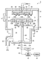
- FIG. 1 is a schematic cross-sectional view showing a processing apparatus according to an embodiment of the present invention
- FIG. 2 is a plan view showing a heating mechanism provided on the mounting table of the mounting table device provided in the processing apparatus.
- a film forming process is performed by CVD on a semiconductor wafer which is an object to be processed will be described as an example.
- the processing apparatus 2 includes a processing container 4 formed into a cylindrical shape from, for example, nickel, a nickel alloy, or an aluminum alloy.
- a shower head portion 6 having a large number of gas ejection holes 6A and 6B on the lower surface as a gas supply mechanism is provided on the ceiling portion of the processing vessel 4 so that, for example, a film forming gas is used as the processing gas in the processing vessel 4. It can be introduced into the processing space S.
- the shower head 6 is divided into, for example, two gas spaces 8A and 8B, and the gas ejection holes 6A and 6B communicate with the gas spaces 8A and 8B, respectively. It is a so-called postmix type in which gas can be mixed for the first time.
- the entire shower head portion 6 is made of, for example, nickel, a nickel alloy, an aluminum alloy, or the like.
- the ceiling portion of the processing container 4 having the shower head portion 6 is attached to the upper end of the side wall of the processing container 4 via a seal member 10 made of, for example, an O-ring so as to maintain the airtightness in the processing container 4. It has become.
- a loading / unloading port 12 for loading / unloading a semiconductor wafer W as an object to be processed is formed on the side wall of the processing container 4, and a gate valve 14 is provided in the loading / unloading port 12 to be opened and closed. .
- a load lock chamber or a transfer chamber (not shown) is connected to the gate valve 14.
- a concave portion 17 that is depressed downward is formed on the center side of the bottom portion 16 of the processing container 4, and the inside of the concave portion 17 serves as an exhaust space 18.
- An exhaust port 20 is provided in the lower side wall of the concave portion 17 that defines the exhaust space 18.
- the exhaust port 20 is connected to a vacuum exhaust system 22 in which a pressure control valve and a vacuum pump (not shown) are provided in the middle, and the inside of the processing container 4 is evacuated by the vacuum exhaust system 22 to obtain a predetermined pressure. To be maintained.
- a mounting table device 24 for mounting a semiconductor wafer, which is an object to be processed is provided.
- the mounting table device 24 has a mounting table 26 on which the wafer W is actually mounted on its upper surface, and leg portions 28 that are connected to the center of the lower surface of the mounting table 26 and extend downward to support the mounting table 26 horizontally. And have.
- the lower end of the leg portion 28 is supported by the bottom portion 16 ⁇ / b> A of the concave portion 17 that defines the exhaust space 18.
- the leg portion 28 has a hollow shape, that is, a cylindrical shape, and an open lower end.
- Both the mounting table 26 and the leg portion 28 are made of a ceramic material such as AlN. One of these may be formed of a ceramic material.
- a resistance heater 30 is embedded in the upper part of the mounting table 26 as a heating mechanism for heating the wafer W mounted thereon.
- the resistance heater 30 is made of, for example, molybdenum wire, and as shown in FIG. 2, the resistance heater 30 is divided into an inner zone heater 32A and an outer zone heater 32B in a concentric manner. Two heating zones of the outer heating zone are formed, and the heating temperature can be controlled for each zone.
- the ceramic heater is comprised by the mounting base 26 and the resistance heater 30 which consist of ceramic materials.
- the number of zones is not particularly limited, and may be three or more zones.
- connection terminals of the heaters 32A and 32B in each zone are located at the center of the mounting table 26 (see FIG. 1), and power supply rods 36A and 36B made of, for example, Ni are respectively connected to these connection terminals by, for example, Ni—Au brazing. It is joined.
- power supply rods 36A and 36B extend downward, extend through the hollow leg portion 28 to the outside, and are connected to a power supply unit 37 that supplies electric power.
- feeding rod 36A, 36B Note that only one feeding rod 36A, 36B is shown in FIG. 1, but two feeding rods are actually provided.
- the upper end of the ceramic leg portion 28 is airtightly joined to the lower surface of the central portion of the mounting table 26.
- a mounting flange portion 28A at the lower end of the leg portion 28 is airtightly attached to the bottom portion 16A of the concave portion 17 that defines the exhaust space 18. Note that the leg portion 28, an inert gas such as N 2 gas are supplied.
- the mounting table 26 has a diameter of about 340 mm and the leg portion 28 has a diameter of about 40 to 50 mm.
- a temperature measuring unit 38 is provided at the center of the back surface side (lower surface side) of the mounting table 26 so as to correspond to the innermost heating zone, here, the inner heating zone 34A, and the temperature of the inner heating zone 34A is set. It can be measured.
- a thermocouple can be used, for example, and this thermocouple is attached to the center of the back surface of the mounting table 26 by fusion. In this case, since the temperature measuring unit 38 made of the thermocouple is housed in the leg portion 28, the thermocouple is not exposed to various gases supplied into the processing container 4, and the thermocouple Corrosion is prevented.
- the wiring 40 extending from the temperature measuring unit 38 passes through the bottom 16A side and is drawn to the outside, and is connected to a power supply control unit 42 made of, for example, a microprocessor (computer).
- the power supply control unit 42 can control the heaters 32A and 32B in the heating zone based on the detection value of the temperature measurement unit 38.
- the inner zone heater 32A of the inner heating zone 34A is feedback controlled so as to maintain the process temperature of the film forming process.
- the outer zone heater 32B of the outer heating zone 34B is supplied with power to the inner zone heater 32A regardless of the control mode such as current control, voltage control, and power control. Is set so that power determined by a predetermined safe supply power ratio is supplied, and open loop control is performed.
- control is performed so that 0.8 times the power supplied to the inner zone heater 32A is supplied to the outer zone heater 32B.
- the current control is to output an operation amount corresponding to the difference between the set temperature and the actual temperature as a current form
- the voltage control is to output this difference as a voltage. This difference is output as electric power.
- the safety supply power ratio is determined so that the temperature difference between the heating zones is within a range in which the mounting table 26 is not damaged. Depending on the process temperature, the in-plane uniformity of the film thickness is slightly increased. There is a case where the power ratio is set so as to prevent the mounting table 26 from being damaged even if it is lowered. This point will be described later.
- the power supply control unit 42 In addition to controlling the operation of the mounting table device 24, the power supply control unit 42 also has a function of controlling the entire operation of the processing device 2, and the power supply control unit 42 controls the operation thereof.
- a storage medium 44 storing the program is connected.
- the storage medium 44 for example, a flexible disk, a flash memory, or the like can be used.
- the mounting table 26 is formed with a plurality of pin holes 46 penetrating in the vertical direction, and each pin hole 46 has a lower end commonly connected to a connection ring 48, for example, made of quartz.
- the pin 50 is accommodated in a loosely fitted state.
- the connecting ring 48 is connected to an upper end of a retracting rod 52 that is provided so as to be vertically movable through the bottom of the container.
- the lower end of the retracting rod 52 is connected to an air cylinder 54.
- a bellows 56 that can be expanded and contracted is provided in a through-hole portion of the retractable rod 52 with respect to the bottom of the container so that the retractable rod 52 can be raised and lowered while maintaining the airtightness in the processing container 4. ing.
- a film forming method (including a temperature control method) performed using the processing apparatus 2 configured as described above will be described.
- the vacuum exhaust system 22 The inside of the processing container 4 is maintained at a predetermined process pressure, and a predetermined processing gas (film forming gas) is introduced into the processing container 4 from the shower head unit 6 serving as a gas supply means, and is predetermined on the wafer W by CVD.
- the thin film is formed.
- NH 3 gas is supplied to one gas space 8A of the shower head unit 6, and TiCl 4 + N 2 gas is supplied to the other gas space 8B.
- TiCl 4 + N 2 gas is supplied to the other gas space 8B.
- Each of these gases is mixed in the processing space S to perform a TiN film forming process.
- the power supply control unit 42 controls the power supply unit 37 based on the measurement value from the temperature measurement unit 38 made of a thermocouple provided at the center of the lower surface of the mounting table 26.
- the operation amount to the zone heaters 32A and 32B is controlled via
- the supply voltage to the inner zone heater 32A of the inner heating zone 34A is feedback controlled so as to maintain the process temperature of the film forming process (voltage control).
- the outer zone heater 32B of the outer heating zone 34B has a power determined by a predetermined safe supply power ratio based on the power supplied to the inner zone heater 32A (not the supply voltage). It is set and open loop control is performed. Thereby, it is possible to prevent the temperature difference between the inner and outer circumferences of the mounting table 26 from becoming excessively large, and to prevent the mounting table 26 from being damaged.
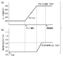
- the temperature distribution of the mounting table 26 is such that the temperature at the center of the mounting table 26 is the lowest and gradually increases as it approaches the peripheral part (edge part), that is, the temperature distribution state of the center cool. It has become. The state of this temperature distribution will be described with reference to FIG.
- FIG. 3 is a diagram schematically showing the relationship between the processing gas concentration and the temperature distribution in the diameter direction of the semiconductor wafer.
- the processing gas is generally supplied to the processing space from a shower head unit 6 provided on the ceiling of the processing container, and is diffused substantially uniformly toward the periphery of the mounting table 26 while flowing down into the processing space. Thus, air is exhausted from below the mounting table 26. Therefore, the concentration of the processing gas supplied from the shower head unit 6 to the processing space is high at the wafer center and gradually decreases toward the edge. Accordingly, if the wafer temperature is uniform over the entire surface, the reaction in the portion (center portion) where the gas concentration is high is promoted, and the film thickness of this portion becomes thicker than other portions (edge portions), which is not preferable. .
- the temperature difference ⁇ t between the wafer center and the edge is about 5 ° C., for example.
- the upper limit of the temperature difference ⁇ t is about 33 ° C., and it is desirable to set the temperature difference ⁇ t to 33 ° C. or less to prevent damage. It is.
- the feedback control is performed based on the measured value in the temperature measurement unit composed of the thermocouple for the inner heater, and the process temperature is determined for the temperature of the outer heater.
- the current ratio or voltage ratio that provides the best in-plane film thickness uniformity is determined in advance, and the current and voltage corresponding to the current ratio and voltage ratio are maintained using the inner heater as a reference. In this way, the outer heater was controlled by open loop.
- the outer zone heater 32B is controlled by the power ratio as described above instead of the current ratio or voltage ratio.
- the power ratio is controlled so that the in-plane uniformity of the film thickness is always at the highest level, the temperature difference ⁇ t sometimes increases beyond 33 ° C., in such a case, Even if the in-plane uniformity of the film thickness is slightly reduced, the power ratio is set such that the mounting table 26 is not damaged.
- the supply power ratio (OUT / IN) at which the in-plane uniformity of the film thickness is the best for various process temperatures for example, various process temperatures in the range of about 400 to 900 ° C. Is obtained in advance.
- the supply power ratio is “0.65”
- the supply power ratio is “0.70”.
- the supply power to the outer zone heater 32B is controlled with the supply power ratio as described above according to the process temperature, the optimum center cool state is obtained, and the in-plane uniformity of the film thickness is the best. In this state, a thin film can be obtained. In this case, the mounting table 26 may be damaged depending on conditions.
- a limit is imposed on the supply power ratio. That is, first, at various process temperatures (660 ° C. or less), the power control is performed on the outer zone heater 32B with the above-described power supply ratio to actually perform the film forming process. We examined whether or not. Note that feedback control was performed so as to maintain the set process temperature for the inner zone heater 32A. The result at that time is shown in FIG. In FIG. 5, the horizontal axis indicates the number of heaters for which experiments were performed.
- the supply power ratio is set as the safe supply power ratio.
- the supply power ratio at which the in-plane uniformity of the best film thickness is obtained exceeds 1.00
- “1.00” is set as the safe supply power ratio at the process temperature. That is, here, when the supply power ratio exceeds “1.00”, the in-plane uniformity of the film thickness is slightly sacrificed to make the mounting table 26 safe.
- the same examination as described above was performed when the process temperature was higher than 660 ° C. As a result, it was found that in the case of a process temperature higher than 660 ° C., if the supply power ratio is “0.82” or less, the mounting table 26 is not damaged.
- the safe supply power ratio for each process temperature obtained as described above is stored in the power supply control unit 42 in advance. Therefore, if the temperature control according to this supply power ratio is performed, the temperature difference ⁇ t between the inner and outer circumferences of the mounting table 26 can be controlled within 33 ° C. in the temperature distribution state of the center cool. Can be prevented.
- FIG. 6 is a graph showing the range of the supply power ratio that is allowed depending on the process temperature.
- the control range in the case of control by the conventional supply voltage ratio is also shown.
- the center cool state becomes larger as it goes to the right side
- the center hot state becomes as it goes to the left side.
- the supply power ratio is allowed in the range of 0.38 to 1.00.
- the supply power ratio is 0. It is allowed in the range of 38 to 0.82.
- the mounting table crack may occur in the area A1 shown on the right side, which is not preferable.
- FIG. 7A shows the case of the conventional voltage ratio control
- FIG. 7B shows the case of the power ratio control of the present invention.
- the left vertical axis represents the heater temperature (inner zone heater)
- the right vertical axis represents the operation amount.
- the operation amount 100% indicates 200 volts
- the operation amount 100% indicates 4000 watts.
- the set process temperature at this time is 700 ° C.
- the set supply voltage ratio (in the case of FIG. 7A) and supply power ratio (in the case of FIG. 7B) are “0.95” and “0.82”, respectively.
- the change in the operation amount of each heater and the change in the heater temperature from the wafer loading are shown.
- the temperature until the temperature stabilizes after the wafer loading is a very large value.
- Such a large temperature fluctuation amount H1 causes a large temperature difference between the inner and outer periphery of the mounting table 26, and as a result, the mounting table 26 is damaged.
- the temperature fluctuation amount H2 until the temperature becomes stable after the wafer is loaded is considerably small, which is about half that in the case of FIG. 7A. It has become.
- the temperature difference generated between the inner and outer periphery of the mounting table 26 does not become so large, and it is possible to prevent the mounting table 26 from being damaged, and it can be seen that good results are shown.
- the temperature control of the mounting table 26 when the process is actually performed has been described.
- the mounting table 26 is not cracked even when the mounting table 26 is heated and lowered.
- Temperature control is required.
- the temperature of the inner heating zone 34A is maintained at a predetermined temperature difference, for example, 33 ° C. or less, lower than the temperature of the outer heating zone 34B.
- the temperature is raised or lowered in the center hot state, or the temperature difference is lowered to 33 ° C. or less in the center cool state.
- the temperature difference is set to about 70 ° C. or more, for example, the mounting table 26 is damaged as described above.
- the heater temperature is maintained at 300 ° C., and the supply power ratio at this time is maintained at “0.58”. In this case, control is performed so that the inner peripheral temperature of the mounting table becomes a center hot state higher than the outer peripheral temperature. Then, the heater is heated at a rate of temperature increase of about 5 ° C./min, for example, by increasing the power supplied to both heaters while maintaining the above supply power ratio, that is, maintaining the center hot state. .
- the heater temperature reaches 700 ° C., which is the process temperature (set temperature)
- the supply power ratio gradually becomes the safe supply power ratio.
- the temperature distribution of the mounting table is gradually shifted from the center hot state to the center cool state.
- the heater temperature may be controlled so as to reverse the above process.
- the temperature difference between the inner and outer circumferences of the mounting table can be set to a temperature difference that does not break even when the heater is raised or lowered, it is possible to prevent the mounting table from being damaged.
- the present invention is not limited to the above embodiment and can be variously modified.
- each numerical example used in the above description is merely an example, and it goes without saying that the numerical value also changes depending on the design of the mounting table 26, the resistance heater 30, and the like.
- the present invention is not limited to this, and the present invention is applied to various heat treatments such as an etching process, an oxidation diffusion process, an annealing process, and a modification process.
- the present invention can be applied to a plasma processing apparatus.
- the present invention is not limited to this, and the present invention is also applied to a case where three or more heating zones are provided concentrically. can do.
- the temperature difference between the innermost heating zone and the outermost heating zone is a temperature range in which the mounting table is not broken, for example, within 33 ° C.
- the safety supply power ratio is set in the temperature range.
- the object to be processed is not limited to a semiconductor wafer, and an LCD substrate, a glass substrate, a ceramic substrate, or the like can also be used.
Landscapes
- Engineering & Computer Science (AREA)
- Chemical & Material Sciences (AREA)
- Condensed Matter Physics & Semiconductors (AREA)
- General Physics & Mathematics (AREA)
- Manufacturing & Machinery (AREA)
- Computer Hardware Design (AREA)
- Microelectronics & Electronic Packaging (AREA)
- Power Engineering (AREA)
- Physics & Mathematics (AREA)
- Chemical Kinetics & Catalysis (AREA)
- Materials Engineering (AREA)
- General Chemical & Material Sciences (AREA)
- Mechanical Engineering (AREA)
- Metallurgy (AREA)
- Organic Chemistry (AREA)
- Chemical Vapour Deposition (AREA)
- Drying Of Semiconductors (AREA)
- Container, Conveyance, Adherence, Positioning, Of Wafer (AREA)
Priority Applications (2)
| Application Number | Priority Date | Filing Date | Title |
|---|---|---|---|
| CN2009801015849A CN101911252B (zh) | 2008-01-19 | 2009-01-07 | 载置台装置、处理装置以及温度控制方法 |
| KR1020127015727A KR20120085915A (ko) | 2008-01-19 | 2009-01-07 | 처리 장치 및 온도 제어 방법 |
Applications Claiming Priority (2)
| Application Number | Priority Date | Filing Date | Title |
|---|---|---|---|
| JP2008009925A JP5358956B2 (ja) | 2008-01-19 | 2008-01-19 | 載置台装置、処理装置、温度制御方法及び記憶媒体 |
| JP2008-009925 | 2008-01-19 |
Publications (1)
| Publication Number | Publication Date |
|---|---|
| WO2009090899A1 true WO2009090899A1 (ja) | 2009-07-23 |
Family
ID=40885290
Family Applications (1)
| Application Number | Title | Priority Date | Filing Date |
|---|---|---|---|
| PCT/JP2009/050058 Ceased WO2009090899A1 (ja) | 2008-01-19 | 2009-01-07 | 載置台装置、処理装置および温度制御方法 |
Country Status (5)
| Country | Link |
|---|---|
| JP (1) | JP5358956B2 (enExample) |
| KR (2) | KR101374442B1 (enExample) |
| CN (1) | CN101911252B (enExample) |
| TW (1) | TWI469237B (enExample) |
| WO (1) | WO2009090899A1 (enExample) |
Cited By (4)
| Publication number | Priority date | Publication date | Assignee | Title |
|---|---|---|---|---|
| EP3187620A4 (en) * | 2014-08-28 | 2018-03-28 | Boe Technology Group Co. Ltd. | Evaporation equipment and evaporation method |
| CN111801777A (zh) * | 2018-07-03 | 2020-10-20 | 东京毅力科创株式会社 | 基板处理系统和基板处理方法 |
| US10921773B2 (en) | 2015-06-24 | 2021-02-16 | Tokyo Electron Limited | Temperature control method |
| US12379720B2 (en) * | 2016-02-17 | 2025-08-05 | Lam Research Corporation | Common terminal heater for ceramic pedestals used in semiconductor for fabrication |
Families Citing this family (19)
| Publication number | Priority date | Publication date | Assignee | Title |
|---|---|---|---|---|
| JP5026549B2 (ja) * | 2010-04-08 | 2012-09-12 | シャープ株式会社 | 加熱制御システム、それを備えた成膜装置、および温度制御方法 |
| CN103628046B (zh) * | 2012-08-24 | 2015-11-11 | 中微半导体设备(上海)有限公司 | 一种调节基片表面温度的控温系统和控温方法 |
| CN102851652A (zh) * | 2012-09-28 | 2013-01-02 | 深圳市捷佳伟创新能源装备股份有限公司 | 一种用于mocvd设备的加热器 |
| JP2014112594A (ja) * | 2012-12-05 | 2014-06-19 | Denso Corp | スーパージャンクション構造を有する半導体装置の製造方法 |
| CN104131268B (zh) * | 2013-05-03 | 2017-02-08 | 北京北方微电子基地设备工艺研究中心有限责任公司 | 分区域加热方法、装置和半导体设备 |
| DE102013109155A1 (de) * | 2013-08-23 | 2015-02-26 | Aixtron Se | Substratbehandlungsvorrichtung |
| CN104716077A (zh) * | 2015-03-25 | 2015-06-17 | 上海华力微电子有限公司 | 可控温加热式传送腔及其工艺装置和控温加热方法 |
| JP6525751B2 (ja) * | 2015-06-11 | 2019-06-05 | 東京エレクトロン株式会社 | 温度制御方法及びプラズマ処理装置 |
| JP6447393B2 (ja) | 2015-07-06 | 2019-01-09 | 東京エレクトロン株式会社 | 成膜処理装置、成膜処理方法及び記憶媒体 |
| JP6507953B2 (ja) | 2015-09-08 | 2019-05-08 | 東京エレクトロン株式会社 | 基板処理装置及び基板処理方法 |
| CN107022754B (zh) | 2016-02-02 | 2020-06-02 | 东京毅力科创株式会社 | 基板处理装置 |
| JP6740881B2 (ja) | 2016-02-02 | 2020-08-19 | 東京エレクトロン株式会社 | 基板処理装置 |
| JP6688172B2 (ja) * | 2016-06-24 | 2020-04-28 | 東京エレクトロン株式会社 | 基板処理システムおよび方法 |
| CN109417024B (zh) * | 2016-06-27 | 2023-07-28 | 东京毅力科创株式会社 | 基板处理装置、基板处理方法以及存储介质 |
| CN108054087B (zh) * | 2017-12-07 | 2020-05-29 | 德淮半导体有限公司 | 晶圆键合中的退火装置及退火方法 |
| JP7018823B2 (ja) * | 2018-05-29 | 2022-02-14 | 東京エレクトロン株式会社 | モデル生成装置、モデル生成プログラムおよびモデル生成方法 |
| US12288672B2 (en) | 2020-01-15 | 2025-04-29 | Applied Materials, Inc. | Methods and apparatus for carbon compound film deposition |
| JP7449799B2 (ja) * | 2020-07-09 | 2024-03-14 | 東京エレクトロン株式会社 | 載置台の温度調整方法及び検査装置 |
| KR102844318B1 (ko) * | 2023-12-19 | 2025-08-08 | 주식회사 에스지에스코리아 | 멀티 존 히터의 제어 장치 및 제어 방법 |
Citations (2)
| Publication number | Priority date | Publication date | Assignee | Title |
|---|---|---|---|---|
| JP2005243243A (ja) * | 2004-02-24 | 2005-09-08 | Ngk Insulators Ltd | 加熱方法 |
| JP2007335500A (ja) * | 2006-06-13 | 2007-12-27 | Hitachi Kokusai Electric Inc | 基板処理装置の温度制御方法 |
Family Cites Families (2)
| Publication number | Priority date | Publication date | Assignee | Title |
|---|---|---|---|---|
| JP2001313260A (ja) * | 2000-04-28 | 2001-11-09 | Kyocera Corp | 円盤状ヒータおよびウエハ処理装置 |
| JP4009100B2 (ja) * | 2000-12-28 | 2007-11-14 | 東京エレクトロン株式会社 | 基板加熱装置および基板加熱方法 |
-
2008
- 2008-01-19 JP JP2008009925A patent/JP5358956B2/ja active Active
-
2009
- 2009-01-07 CN CN2009801015849A patent/CN101911252B/zh active Active
- 2009-01-07 KR KR1020107014192A patent/KR101374442B1/ko active Active
- 2009-01-07 KR KR1020127015727A patent/KR20120085915A/ko not_active Ceased
- 2009-01-07 WO PCT/JP2009/050058 patent/WO2009090899A1/ja not_active Ceased
- 2009-01-16 TW TW98101551A patent/TWI469237B/zh not_active IP Right Cessation
Patent Citations (2)
| Publication number | Priority date | Publication date | Assignee | Title |
|---|---|---|---|---|
| JP2005243243A (ja) * | 2004-02-24 | 2005-09-08 | Ngk Insulators Ltd | 加熱方法 |
| JP2007335500A (ja) * | 2006-06-13 | 2007-12-27 | Hitachi Kokusai Electric Inc | 基板処理装置の温度制御方法 |
Cited By (6)
| Publication number | Priority date | Publication date | Assignee | Title |
|---|---|---|---|---|
| EP3187620A4 (en) * | 2014-08-28 | 2018-03-28 | Boe Technology Group Co. Ltd. | Evaporation equipment and evaporation method |
| US10921773B2 (en) | 2015-06-24 | 2021-02-16 | Tokyo Electron Limited | Temperature control method |
| US12474686B2 (en) | 2015-06-24 | 2025-11-18 | Tokyo Electron Limited | Substrate processing apparatus and substrate processing method |
| US12379720B2 (en) * | 2016-02-17 | 2025-08-05 | Lam Research Corporation | Common terminal heater for ceramic pedestals used in semiconductor for fabrication |
| CN111801777A (zh) * | 2018-07-03 | 2020-10-20 | 东京毅力科创株式会社 | 基板处理系统和基板处理方法 |
| CN111801777B (zh) * | 2018-07-03 | 2024-04-09 | 东京毅力科创株式会社 | 基板处理系统和基板处理方法 |
Also Published As
| Publication number | Publication date |
|---|---|
| JP5358956B2 (ja) | 2013-12-04 |
| TW200941621A (en) | 2009-10-01 |
| CN101911252A (zh) | 2010-12-08 |
| CN101911252B (zh) | 2012-05-23 |
| JP2009170822A (ja) | 2009-07-30 |
| TWI469237B (zh) | 2015-01-11 |
| KR101374442B1 (ko) | 2014-03-24 |
| KR20100113494A (ko) | 2010-10-21 |
| KR20120085915A (ko) | 2012-08-01 |
Similar Documents
| Publication | Publication Date | Title |
|---|---|---|
| JP5358956B2 (ja) | 載置台装置、処理装置、温度制御方法及び記憶媒体 | |
| JP5135915B2 (ja) | 載置台構造及び熱処理装置 | |
| JP5239988B2 (ja) | 載置台構造及び処理装置 | |
| WO2009116472A1 (ja) | 載置台構造及び熱処理装置 | |
| JP5029435B2 (ja) | 載置台構造及び熱処理装置 | |
| KR101622666B1 (ko) | 기판 처리 장치, 챔버 덮개 구조, 기판의 생산 방법을 기억한 프로그램 및 기판의 생산 방법 | |
| JP5689483B2 (ja) | 基板処理装置、基板支持具及び半導体装置の製造方法 | |
| US11384434B2 (en) | Substrate processing apparatus and heater device | |
| KR20100087248A (ko) | 고유전체막을 형성하기 위한 종형 열처리 장치와 그 구성 부품 및, 보온통 | |
| JP6912497B2 (ja) | 基板処理装置、天井ヒータおよび半導体装置の製造方法 | |
| TWI458033B (zh) | 基板處理裝置,半導體裝置之製造方法及頂板斷熱體 | |
| WO2005064254A1 (ja) | 縦型熱処理装置及びその制御方法 | |
| KR20170077013A (ko) | 기판 처리 장치, 반도체 장치의 제조 방법 및 기록 매체 | |
| JP4853432B2 (ja) | 載置台構造及び処理装置 | |
| US20250069912A1 (en) | Heating device and substrate processing apparatus | |
| KR101767469B1 (ko) | 기판 처리 장치, 반도체 장치의 제조 방법 및 가열부 | |
| JP2010232220A (ja) | 載置台構造、この製造方法及び処理装置 | |
| JP6561148B2 (ja) | 基板処理装置、継手部および半導体装置の製造方法 | |
| US12503768B2 (en) | Substrate processing apparatus, method of manufacturing semiconductor device, method of processing substrate, and gas injector | |
| US20230055506A1 (en) | Substrate processing apparatus, method of manufacturing semiconductor device, method of processing substrate, and gas injector | |
| JP2010272720A (ja) | 基板処理装置及び半導体装置の製造方法 | |
| JP2002141343A (ja) | 熱処理装置設定温度の作成方法、および熱処理方法 | |
| JP2013201333A (ja) | 基板処理装置、半導体装置の製造方法及び基板処理方法 |
Legal Events
| Date | Code | Title | Description |
|---|---|---|---|
| WWE | Wipo information: entry into national phase |
Ref document number: 200980101584.9 Country of ref document: CN |
|
| 121 | Ep: the epo has been informed by wipo that ep was designated in this application |
Ref document number: 09702105 Country of ref document: EP Kind code of ref document: A1 |
|
| ENP | Entry into the national phase |
Ref document number: 20107014192 Country of ref document: KR Kind code of ref document: A |
|
| NENP | Non-entry into the national phase |
Ref country code: DE |
|
| 122 | Ep: pct application non-entry in european phase |
Ref document number: 09702105 Country of ref document: EP Kind code of ref document: A1 |