WO2009087975A1 - NdFeB焼結磁石の製造方法及びNdFeB焼結磁石 - Google Patents
NdFeB焼結磁石の製造方法及びNdFeB焼結磁石 Download PDFInfo
- Publication number
- WO2009087975A1 WO2009087975A1 PCT/JP2009/000068 JP2009000068W WO2009087975A1 WO 2009087975 A1 WO2009087975 A1 WO 2009087975A1 JP 2009000068 W JP2009000068 W JP 2009000068W WO 2009087975 A1 WO2009087975 A1 WO 2009087975A1
- Authority
- WO
- WIPO (PCT)
- Prior art keywords
- powder
- grain boundary
- magnet
- ndfeb
- boundary diffusion
- Prior art date
Links
Images


Classifications
-
- H—ELECTRICITY
- H01—ELECTRIC ELEMENTS
- H01F—MAGNETS; INDUCTANCES; TRANSFORMERS; SELECTION OF MATERIALS FOR THEIR MAGNETIC PROPERTIES
- H01F41/00—Apparatus or processes specially adapted for manufacturing or assembling magnets, inductances or transformers; Apparatus or processes specially adapted for manufacturing materials characterised by their magnetic properties
- H01F41/005—Impregnating or encapsulating
-
- H—ELECTRICITY
- H01—ELECTRIC ELEMENTS
- H01F—MAGNETS; INDUCTANCES; TRANSFORMERS; SELECTION OF MATERIALS FOR THEIR MAGNETIC PROPERTIES
- H01F41/00—Apparatus or processes specially adapted for manufacturing or assembling magnets, inductances or transformers; Apparatus or processes specially adapted for manufacturing materials characterised by their magnetic properties
- H01F41/02—Apparatus or processes specially adapted for manufacturing or assembling magnets, inductances or transformers; Apparatus or processes specially adapted for manufacturing materials characterised by their magnetic properties for manufacturing cores, coils, or magnets
- H01F41/0253—Apparatus or processes specially adapted for manufacturing or assembling magnets, inductances or transformers; Apparatus or processes specially adapted for manufacturing materials characterised by their magnetic properties for manufacturing cores, coils, or magnets for manufacturing permanent magnets
- H01F41/0293—Apparatus or processes specially adapted for manufacturing or assembling magnets, inductances or transformers; Apparatus or processes specially adapted for manufacturing materials characterised by their magnetic properties for manufacturing cores, coils, or magnets for manufacturing permanent magnets diffusion of rare earth elements, e.g. Tb, Dy or Ho, into permanent magnets
-
- H—ELECTRICITY
- H01—ELECTRIC ELEMENTS
- H01F—MAGNETS; INDUCTANCES; TRANSFORMERS; SELECTION OF MATERIALS FOR THEIR MAGNETIC PROPERTIES
- H01F1/00—Magnets or magnetic bodies characterised by the magnetic materials therefor; Selection of materials for their magnetic properties
- H01F1/01—Magnets or magnetic bodies characterised by the magnetic materials therefor; Selection of materials for their magnetic properties of inorganic materials
- H01F1/03—Magnets or magnetic bodies characterised by the magnetic materials therefor; Selection of materials for their magnetic properties of inorganic materials characterised by their coercivity
- H01F1/032—Magnets or magnetic bodies characterised by the magnetic materials therefor; Selection of materials for their magnetic properties of inorganic materials characterised by their coercivity of hard-magnetic materials
- H01F1/04—Magnets or magnetic bodies characterised by the magnetic materials therefor; Selection of materials for their magnetic properties of inorganic materials characterised by their coercivity of hard-magnetic materials metals or alloys
- H01F1/047—Alloys characterised by their composition
- H01F1/053—Alloys characterised by their composition containing rare earth metals
- H01F1/055—Alloys characterised by their composition containing rare earth metals and magnetic transition metals, e.g. SmCo5
- H01F1/0555—Alloys characterised by their composition containing rare earth metals and magnetic transition metals, e.g. SmCo5 pressed, sintered or bonded together
- H01F1/0557—Alloys characterised by their composition containing rare earth metals and magnetic transition metals, e.g. SmCo5 pressed, sintered or bonded together sintered
-
- H—ELECTRICITY
- H01—ELECTRIC ELEMENTS
- H01F—MAGNETS; INDUCTANCES; TRANSFORMERS; SELECTION OF MATERIALS FOR THEIR MAGNETIC PROPERTIES
- H01F1/00—Magnets or magnetic bodies characterised by the magnetic materials therefor; Selection of materials for their magnetic properties
- H01F1/01—Magnets or magnetic bodies characterised by the magnetic materials therefor; Selection of materials for their magnetic properties of inorganic materials
- H01F1/03—Magnets or magnetic bodies characterised by the magnetic materials therefor; Selection of materials for their magnetic properties of inorganic materials characterised by their coercivity
- H01F1/032—Magnets or magnetic bodies characterised by the magnetic materials therefor; Selection of materials for their magnetic properties of inorganic materials characterised by their coercivity of hard-magnetic materials
- H01F1/04—Magnets or magnetic bodies characterised by the magnetic materials therefor; Selection of materials for their magnetic properties of inorganic materials characterised by their coercivity of hard-magnetic materials metals or alloys
- H01F1/047—Alloys characterised by their composition
- H01F1/053—Alloys characterised by their composition containing rare earth metals
- H01F1/055—Alloys characterised by their composition containing rare earth metals and magnetic transition metals, e.g. SmCo5
- H01F1/057—Alloys characterised by their composition containing rare earth metals and magnetic transition metals, e.g. SmCo5 and IIIa elements, e.g. Nd2Fe14B
Definitions
- the present invention relates to a method for producing a NdFeB sintered magnet having a high coercive force and the NdFeB sintered magnet.
- NdFeB sintered magnets are expected to increase in demand in the future for use in motors such as hybrid cars, and the coercive force H cJ is required to be further increased.
- H cJ coercive force
- a method of replacing part of Nd with Dy or Tb is known, but Dy and Tb resources are scarce and unevenly distributed worldwide. Further, there is a problem that the residual magnetic flux density Br and the maximum energy product (BH) max of the NdFeB sintered magnet are reduced by substitution of these elements.
- Patent Document 1 discloses that Nd, Pr, Dy, Ho, and Tb are formed on the surface of the NdFeB sintered magnet in order to prevent a decrease in coercive force that occurs when the surface of the NdFeB sintered magnet is processed for the purpose of thinning the film. It is described that at least one kind is deposited. Patent Document 2 describes that irreversible demagnetization that occurs at high temperatures is suppressed by diffusing at least one of Tb, Dy, Al, and Ga on the surface of the NdFeB sintered magnet.
- Patent Document 4 alloy powders of Dy and Tb and other metals have been deposited on the surface of sintered NdFeB magnets (Patent Document 4), and fluoride powders of Dy and Tb and one or more selected from Al, Cu, and Zn are used.
- Patent Document 5 A method of realizing a high coercive force by depositing a mixed powder with a powder (Patent Document 5) and then performing a heat treatment has been found.
- Patent Documents 1 and 2 have a low effect of improving the coercive force.
- a method of attaching a component containing Dy or Tb to the magnet surface by sputtering or ion plating is expensive and is not practical.
- the method of attaching a component containing Dy or Tb by applying a powder of DyF 3 or Dy 2 O 3 or TbF 3 or Tb 2 O 3 to the magnet surface (Patent Document 3) is inexpensive. Although advantageous in some respects, the coercivity values that can be reached by this method are not very large.
- the methods of Patent Documents 4 and 5 are not particularly advantageous compared to the methods of Patent Document 3 and Non-Patent Document 4, and the coercive force value obtained is also small.
- the conventional technologies shown in (3) and (4) use Dy, which is far more abundant than Tb in terms of resources, for practical applications with a thickness of 3 mm or more and a sufficiently large magnetic pole area. It was impossible to obtain a coercive force of 1.6 MA / m or more by using a base material not containing Dy or Tb (NdFeB sintered magnet before the grain boundary diffusion treatment) by the grain boundary diffusion treatment.
- Non-Patent Document 4 it can be read from the graph therein that when the thickness is 3 mm, HcJ ⁇ 1.2 MA / m by the grain boundary diffusion treatment with TbF 3 . Compared with TbF 3 , DyF 3 is much less effective at increasing the coercive force due to grain boundary diffusion, so when DyF 3 is applied to the same 3 mm NdFeB sintered magnet, the resulting H cJ is 1.2 MA. It is assumed that it is much smaller than / m. In Patent Document 4, an Nd, Dy, Al, Cu, B, Fe, Co alloy containing 15 at% (about 30 mass%) of Dy is compared with a 2 mm thick NdFeB sintered magnet that does not contain Dy or Tb.
- H cJ 1.178 MA / m can be obtained by performing grain boundary diffusion treatment with powder. Even in an example using an alloy powder containing 15 at% (about 30 mass%) of Dy and added with various additive elements, the maximum reachable H cJ is 1.290 MA / m for a 2.5 mm thick NdFeB sintered magnet. .
- H cJ obtained by the grain boundary diffusion treatment by mixed powder of a powder of DyF 3 powder and Al is 1.003 ⁇ 1.082MA / m. It is said that a maximum of 1.472 MA / m HcJ can be obtained by a grain boundary diffusion method using a mixed powder of Zn powder and DyF 3 powder for a 4 mm thick NdFeB sintered body containing no Dy or Tb.
- Patent Document 6 a slit is provided on the surface of a thick magnet and the effect of grain boundary diffusion is exerted on the deep part of the magnet, and in Patent Document 7, only the vicinity of the surface of a thick magnet is made highly coercive by the grain boundary diffusion method. Attempts have been made to increase the heat resistance of magnets.
- Patent Document 6 causes disadvantages in use, such as an increase in processing costs and surface treatment costs, or a decrease in mechanical strength.
- Patent Document 7 cannot be used for applications that require high reliability. Increasing the coercive force of NdFeB sintered magnets has become more important with the expansion of applications to relatively large motors and generators. In these applications, there is a great demand for magnets with a thickness of 5 mm or more or 6 mm or more, and meeting that need is an extremely important issue.
- the problem to be solved by the present invention is that a NdFeB sintered magnet can obtain a high coercive force that has not been achieved by the conventional technology by a grain boundary diffusion method, and a relatively thick magnet having a thickness of 4 mm or more.
- high squareness is achieved, and a means capable of increasing the coercive force even for a thick NdFeB sintered magnet having a thickness of 5 mm or more or 6 mm or more is obtained.
- the target for the coercive force is Nd or Pr only as a rare earth component.
- the present invention makes it possible to stably produce a high coercivity NdFeB sintered magnet. Since the results of the present invention can be applied to Tb, if the present invention is implemented using Tb, the present invention becomes a useful technique for special applications that require higher H cJ . In addition, by using a substrate in which Dy or Tb is used, the value of HcJ can be further increased according to the application. By applying the method of the present invention, it becomes possible to produce NdFeB sintered magnets with a combination of high B r and high H cJ , which was impossible until now, and solved the resource problems of Dy and Tb. Will be.
- the first aspect of the method for producing a sintered NdFeB magnet according to the present invention which has been made to solve the above-mentioned problems, is that after forming a layer containing Dy and / or Tb on the surface of the NdFeB sintered magnet body base material NdFeB for performing a grain boundary diffusion treatment in which Dy and / or Tb in the layer is diffused into the inside of the magnet base material through the crystal grain boundary of the magnet base material by heating to a temperature below the sintering temperature of the magnet base material.
- the layer is a powder layer formed by powder deposition; c) The powder layer contains 50 mass% or more of metallic Dy and / or Tb, It is characterized by that.
- metal rare earth means a rare earth element constituting a metal in the NdFeB sintered magnet.
- the metal refers to an intermetallic compound including a pure metal, an alloy, and an Nd 2 Fe 14 B phase which is a parent phase. Excludes compounds having ionic or covalent bonds such as rare earth oxides, fluorides, carbides and nitrides.
- Dy and / or Tb in a metal state where the powder layer is 50 mass% or more means that the powder layer is Dy and / or Tb in a metal state, that is, the powder layer is 100 mass%, Dy and / or Tb.
- Dy and / or Tb in the metal state means Dy and / or Tb constituting the metal in the powder layer applied to the base material for the grain boundary diffusion treatment.
- the metal includes pure metals, alloys, and intermetallic compounds, and does not include these rare earth fluorides, carbides, oxides, and nitrides.
- These rare earth hydrides or hydrides of intermetallic compounds containing these rare earths are a kind of intermetallic compounds, and the rare earths constituting them are considered to be in a metallic state.
- Most of the hydrogen contained in these hydrides separates from the powder layer before Dy and Tb begin to diffuse into the substrate. Therefore, hydrogen in the hydride is not included in the calculation of the composition of the powder layer. When the composition is expressed in mass%, the difference in atomic weight between the rare earth and hydrogen is very large, so the calculated value hardly changes depending on whether or not hydrogen is actually included in the composition calculation.
- NdFeB sintered magnet Nd rich phase and B rich phase exist in addition to the main phase Nd 2 Fe 14 B phase.
- the present inventor has found that a sufficient amount of the Nd-rich phase in the metal state needs to be present in the crystal grain boundary in order for the grain boundary diffusion method of the NdFeB sintered magnet to work effectively.
- Dy and Tb are fed from the layer containing a large amount of Dy and Tb formed on the surface to the inside of the sintered compact substrate through the grain boundary.
- the condition of a) is indispensable in order to increase the diffusion rate of Dy and Tb through the grain boundary and accelerate the diffusion to the deep part of the substrate. If there is a certain amount of rare earth in excess of the metal phase than the stoichiometric composition of the main phase, a thick melted Nd-rich phase passage is formed at the grain boundary during the grain boundary diffusion treatment, and Dy and Fast diffusion of Tb into the base material becomes possible.
- the amount of the rare earth in the metallic state necessary as a base material to obtain a high coercive force of 1.6 MA / m or 1.7 MA / m or more is calculated from the total rare earth amount contained in the sintered body base material by oxidation, carbonization. And the amount of rare earths that have been nitrided and changed to rare earth oxides, carbides and nitrides.
- the present inventor has 12.7 at% in excess of the rare earth amount of 11.76 at% as the stoichiometric composition of the Nd 2 Fe 14 B phase, which is about 1 at% excess. We found that it is necessary to be more than%.
- the base material contains a sufficient amount of rare earth in the metal state, a large amount of Nd-rich phase is formed at the grain boundary, and the grain boundary diffusion is effectively performed. As a result, a high coercive force, which was impossible with the conventional grain boundary diffusion method, can be achieved, and the grain boundary diffusion method is effective even for thick substrates.
- the coercive force of the base material itself is increased by reducing the oxygen content of the NdFeB sintered magnet base material
- the increase in the coercive force due to the low oxygen content of the base material is compared with the effect of the present invention.
- a NdFeB sintered magnet having a remarkably large coercive force can be produced by the grain boundary diffusion method, the effect of increasing the coercive force by the grain boundary diffusion process occurs even in a thick magnet, and a relatively square magnet also has a high square shape.
- the NdFeB sintered magnet base material used a large amount of rare earth in the metal state is contained, and a large amount of Nd-rich phase is formed at the grain boundary. This is because grain boundary diffusion of Tb and Tb is likely to occur, and the coercive force increasing effect of these elements penetrates deep into the base material.
- the amount of rare earth in the metal state is analyzed and calculated as follows. First, the total rare earth content, oxygen content, carbon content, and nitrogen content contained in the NdFeB sintered magnet are chemically analyzed. Assuming that these oxygen, carbon, and nitrogen form R 2 O 3 , RC, and RN, respectively (R is a rare earth element), the total rare earth amount is subtracted from the rare earth amount that is not in the metallic state by oxygen, carbon, and nitrogen. It is assumed that the difference is the amount of rare earth metal.
- the amount of rare earth in the substrate thus obtained is 12.7 at% or more as described above, the inventor has a large magnetic pole area and a thickness of 3 mm for a substrate not containing Dy or Tb. It was found that a high coercive force of 1.6 MA / m and further 1.7 MA / m can be obtained by the grain boundary diffusion treatment with Dy even when it is relatively thick.
- condition b This condition is necessary to industrially implement the grain boundary diffusion method for NdFeB sintered magnets.
- Conventionally known sputtering methods have low productivity and are too expensive to process, resulting in no industrial value.
- the barrel painting method (see Japanese Patent Application Laid-Open No. 2004-359873) is optimal as a method for applying the powder to the substrate surface.
- a coating method using a solvent such as a spray method is also possible.
- the present invention satisfies the condition a)
- a sufficient amount of rare earth in the metal state is present in the substrate, and a large amount of rare earth-rich phase is present at the grain boundary, a large amount of metal is present on the surface of the substrate.
- a layer containing Dy and Tb in the state is deposited, a large amount of these metals diffuses into the base material deep through the grain boundary, and as a result, an NdFeB sintered magnet having a high coercive force that could not be achieved so far can be obtained.
- a second aspect of the method for producing a NdFeB sintered magnet according to the present invention is characterized in that, in the production method of the first aspect, the powder layer is 7 mg or more per 1 cm 2 of the surface of the magnet substrate. To do. As a result, a large amount of Dy or Tb in a metallic state can be deposited on the surface of the base material, so that a higher coercive force can be achieved.
- a third aspect of the method for producing an NdFeB sintered magnet according to the present invention is characterized in that in the production method of the first or second aspect, the powder layer contains 1 mass% or more of Al. Thereby, the higher coercive force of the NdFeB magnet can be achieved.
- the powder layer contains a total of 10 mass% or more of Co and / or Ni. It is characterized by. Thereby, corrosion resistance can be given to the surface layer formed on the substrate surface after the grain boundary diffusion. That is, the NdFeB sintered magnet manufactured according to the fourth aspect is characterized in that a surface layer in close contact with the base material is formed after grain boundary diffusion, and this surface layer contains a certain amount of Co and Ni. The surface layer exhibits the anticorrosive effect of the substrate.
- the powder layer is melted during grain boundary diffusion treatment. To do.
- the powder used in each embodiment of the present invention is characterized by a high rare earth composition ratio (including 50% or more and 100% rare earth) (c) of the first embodiment) .
- a high rare earth composition ratio including 50% or more and 100% rare earth
- the amount of transition elements such as Fe, Co, Ni, Mn, Cr, and other metal elements such as Al and Cu is increased in addition to rare earth elements such as Nd and Dy, the melting point rapidly decreases, and in certain compositions When a eutectic is formed (eutectic point) and the amount of the element added is increased beyond the composition of the eutectic point, the melting point increases.
- the present inventor made 1.6 MA / m or 1.7 MA / m when the grain boundary diffusion method using only Dy was performed on a substrate not containing Dy or Tb.
- the applied powder layer containing Dy had a high rare earth composition containing pure Dy, and it was desirable to melt all or at least half of the powder layer by eutectic phenomenon. did. That is, during the grain boundary diffusion treatment, the powder layer applied to the base material reacts with itself or with the components of the base material, reaches the composition around the eutectic point, and melts.
- the applied Dy-containing layer When the applied Dy-containing layer is in such a molten state during the grain boundary diffusion treatment, the applied layer and the Nd-rich phase present in the crystal grain boundary reaching the surface from the inside of the substrate are in a liquid state. In this way, Dy in the coating layer is transported into the substrate with high efficiency.
- the powder layer to be applied needs to have a high rare earth composition.
- the powder layer contains Dy and / or Tb in a metallic state at a high concentration of 50 mass% or more, the liquid in which the powder layer is melted is normal at the grain boundary diffusion treatment. Since it is sufficiently high, it does not flow down from the surface of the substrate.
- the composition of the powder layer may be pure Dy.
- the melting point of pure Dy is 1412 ° C, which is higher than the sintering temperature of the NdFeB sintered magnet, but the applied Dy reacts with the Fe of the base material to lower the melting point, and for grain boundary diffusion treatment At a heating temperature of 800-1000 ° C, it forms a eutectic with Fe and melts.
- a preferred range of the composition of the powder layer is a composition range in which the melting point is 1000 ° C. or less before and after the eutectic point on the phase diagram.
- the powder layer and component elements such as Fe contained in the base material form a eutectic and the melting point is Therefore, the applied powder layer melts during the grain boundary diffusion process (usually 1000 ° C. or less), and efficient Dy diffusion occurs.
- the additive element to Dy is increased and the eutectic point is passed and the melting point of the powder layer becomes a composition of 1000 ° C. or higher, the powder layer is heated during grain boundary diffusion treatment.
- the powder layer does not melt completely, and the grain boundary diffusion process proceeds while containing the solid component.
- the applied powder layer remains as a powder layer without melting during the grain boundary diffusion treatment step.
- the composition and heating conditions of the powder layer containing Dy and Tb and melting the powder layer during the grain boundary diffusion treatment it is possible to achieve a high coercivity of the NdFeB sintered magnet.
- the surface layer formed on the surface of the NdFeB sintered magnet base material after the grain boundary diffusion treatment can be adhered to the base material. If the surface layer is easily removed from the base material, it must be removed practically, but if the surface layer is in close contact with the base material, it can be used as it is, or surface treatment can be performed on the surface layer. Reduce the cost of machining.
- Ni or Co is included in the powder layer, the surface layer formed after the grain boundary diffusion treatment comes to have an anticorrosive effect on the base material, and the surface treatment cost can be reduced.
- the first aspect of the NdFeB sintered magnet according to the present invention is a NdFeB sintered magnet in which Dy and / or Tb is diffused by a grain boundary diffusion process.
- the magnet base is a plate magnet base with a thickness of 3.5 mm or more,
- the amount of rare earth in the metal state contained in the plate-like magnet base material is 12.7 at% or more, SQ value indicating the squareness of the magnetization curve is 90% or more, It is characterized by that.
- the SQ value is defined as a value H k / H cJ obtained by dividing the absolute value H k of the magnetic field when the magnetization is reduced by 10% from the maximum value in the magnetization curve by the coercive force H cJ .
- An SQ value of 90% or more means that Dy and / or Tb has diffused to the vicinity of the center of the magnet base material. In this way, a high SQ value of 90% or more was obtained by using a thick plate-like magnet base material of 3.5 mm or more, and the amount of rare earth metal contained in the magnet base material was 12.7 at% or more. This is because Dy and / or Tb easily diffuses into the grain boundary during the grain boundary diffusion treatment.
- the second aspect of the NdFeB sintered magnet according to the present invention is characterized in that in the NdFeB sintered magnet of the first aspect, Al is contained near the grain boundary and near the surface.
- a third aspect of the NdFeB sintered magnet according to the present invention is characterized in that in the NdFeB sintered magnet according to the first or second aspect, Co and / or Ni is contained near the grain boundary and near the surface. To do.
- NdFeB sintered magnet manufacturing method of the first aspect and the NdFeB sintered magnet of the first aspect an NdFeB sintered magnet having a high coercive force and a high remanent magnetization, which could not be achieved by the conventional grain boundary diffusion method, Furthermore, even for thick NdFeB sintered magnets that have been impossible with the grain boundary diffusion method so far, it is possible to produce NdFeB sintered magnets with high squareness and high coercivity. Further, the characteristics can be further improved by the NdFeB sintered magnet manufacturing method of the second to fifth embodiments and the NdFeB sintered magnet of the second to third embodiments.
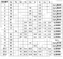
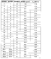
- FIG. 6 is a table showing the composition of the powder used for the grain boundary diffusion treatment in Examples 1 to 3 of the NdFeB sintered magnet according to the present invention and Comparative Example. 6 is a table showing compositions of NdFeB sintered magnet base materials used in Examples 1 to 4 and Comparative Examples.
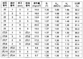
- surface which shows the result of having measured the coercive force about the NdFeB sintered magnet of Example 1 and a comparative example.
- FIG. 6 is a table showing the results of measuring the coercivity and squareness index SQ values of the magnetization curves for relatively thick (5-6 mm thick) substrates for the NdFeB sintered magnets of Example 2 and Comparative Example.
- the NdFeB sintered magnet base material used in the present invention is produced in the same manner as a conventional NdFeB sintered magnet. That is, it is produced by the steps of alloy melting, elementary pulverization, fine pulverization, orientation in a magnetic field, molding, and sintering. However, in the sintered body after sintering, consideration should be given to adjusting the alloy composition so that the amount of rare earth in the metal state is 12.7 at% or more, preferential reduction of rare earths generated during the process, and prevention of impurity contamination Have to do.
- the preferential reduction of the rare earth is a decrease due to evaporation or oxidation of the metallic rare earth component or reaction with the crucible when the alloy is melted, or the Nd-rich phase is pulverized too finely during the pulverization.
- a decrease due to not being collected in the collection container is considered.
- the amount of rare earth in the metallic state is greatly reduced before and after grinding.
- the amount of rare earth in the metal state is also reduced by the chemical reaction of the rare earth in the powder with impurities after the alloy is pulverized.
- the impurities are mainly oxygen, carbon, and nitrogen.
- Oxygen is mainly due to oxidation of the powder during and after alloy grinding, carbon remains in the lubricant added to lubricate the powder, and nitrogen reacts with nitrogen in the air, causing the product to react with nitrogen in the air. Is taken in.
- it is necessary to suppress the reduction of the rare earth amount in the metallic state during the process as much as possible and to suppress the contamination by the impurity element as much as possible. If this is not possible, the amount of rare earth in the alloy must be increased in advance.
- the base material of No. 6 in Example 1 described later is an example in which the amount of rare earth is low, so that contamination by oxygen and carbon is suppressed as much as possible. This is an example in which the amount of rare earth in the metallic state is adjusted within the scope of the present invention by increasing the amount of rare earth.
- the lower limit of the amount of rare earth in the alloy is 12.7 at% added to the decrease in the amount of rare earth during grinding and the amount of rare earth consumed by oxygen, carbon, and nitrogen during or after grinding. If the amount of rare earth in the alloy is large, the present invention can be carried out even if there is a certain amount of contamination by these elements, but if it is too large, the NdFeB sintered magnet will have decreased magnetization and maximum energy product, which is valuable. It will decline. Practically, the upper limit of the amount of rare earth in the alloy is 16 at%. Further, as a kind of rare earth in the alloy, Nd is a main component, but a part of Nd may be substituted with Pr depending on the circumstances of the raw material. Depending on the required coercivity of the final product, part of Nd can be replaced by Dy or Tb.
- the NdFeB sintered body produced in this way is processed into the shape and dimensions required for the final product by machining. Thereafter, the surface is chemically or mechanically cleaned before the grain boundary diffusion treatment.
- the NdFeB sintered magnet thus produced is the base material finally used in the present invention.
- the powder used in the present invention needs to contain 50 mass% or more of Dy and / or Tb in a metallic state.
- alloy powder or mixed powder is used as the powder.
- the alloy powder is obtained by preparing an alloy of Dy or Tb with another metal in advance and then pulverizing it.
- the mixed powder is a pure metal powder of Dy or Tb or a mixture of these pure metal powders and other metal powders.
- These alloy powders or mixed powders may be hydrogenated for pulverization. It is well known that rare earths or alloys containing rare earths become brittle and easy to grind when hydrogenated.
- the hydrogen contained in these metals or alloys can be removed by heating the powder before applying the powder to the base material before the grain boundary diffusion treatment. However, even if some hydrogen remains in the powder, if the powder is applied to the base material for grain boundary diffusion treatment and then heated, the hydrogen will be dispersed before the grain boundary diffusion starts. I leave my body. As the composition of the powder, hydrogen that is released before the grain boundary diffusion, the gas component adsorbed on the powder, or the resin component used for powder coating is not included in the calculation.
- Components other than Dy and Tb of the powder applied to the substrate surface include wettability of the rare earth elements other than Dy and Tb, 3d transition elements such as Fe, Co and Ni, and alloys such as Al and Cu to the substrate. Elements that are considered to be improved, such as B contained in the NdFeB magnet, are appropriately selected. The amount of these elements added is adjusted so that at least half of the powder layer is melted during grain boundary diffusion treatment after powder application. By selecting a powder having such a composition, the object of the present invention can be achieved. A preferred particle size of the powder is 0.1 to 100 ⁇ m.
- An optimum powder coating method for carrying out the present invention is a barrel painting method (see Japanese Patent Application Laid-Open No. 2004-359873).
- an adhesive layer is formed on a NdFeB sintered magnet substrate having a clean surface.
- the optimum thickness of the adhesive layer is 1-5 ⁇ m.
- the adhesive layer forming substance is an adhesive substance and may be anything as long as it does not corrode the substrate surface. Most commonly, liquid organic substances such as epoxy and paraffin are used. When using epoxy or the like, no curing agent is required.
- this adhesive layer coating method a small amount of a liquid organic substance is added and stirred in a container filled with a ceramic or metal ball (referred to as impact media) having a diameter of 0.5 to 1 mm, and then the above-mentioned base material is charged.
- the adhesive layer is formed on the substrate surface by vibrating the entire container.
- the base material on which the adhesive layer is formed is put into the container, the whole container is vibrated, and the powder is applied to the surface of the base material.
- a body layer is formed.
- the amount of powder applied in this way is about 2 mg to about 30 mg per 1 cm 2 of the substrate surface.
- the amount of the powder becomes a certain amount or more. Adjusted to A preferable range of the amount of powder to be applied is 5 mg to 25 mg per 1 cm 2 of the substrate surface.
- the powder coating process is desirably performed in an inert gas in order to prevent oxidation of the powder.
- the powder layer is grown while hitting the powder layer with impact media (ceramic or metal spheres) at the time of powder layer formation.
- the formed powder layer has a relatively high density.
- a method of pressing the powder layer onto the base material with a rubber plate or the like from the powder layer formed by the method implemented in Patent Document 4 is conceivable.
- the base material coated with powder containing Dy or Tb is heated in a heating furnace.
- the atmosphere of the heating furnace is a vacuum or a high purity inert gas atmosphere.
- the gas adsorbed on the powder and the liquid substance components used in barrel painting are released from the powder.
- hydrogen in the powder is released.
- the temperature exceeds 700 ° C.
- the powder reacts with the substrate surface and grain boundary diffusion begins to occur.
- the heating temperature for grain boundary diffusion is desirably 1000 ° C. or lower.
- Standard heating conditions are 800 ° C for 10 hours, or 900 ° C for 3 hours. After heating under such conditions, a heat treatment known as normal post-sintering heat treatment or aging treatment is performed.
- the NdFeB sintered magnet produced by the above-described process has a high coercive force and a high remanent magnetization exceeding the limit of characteristics of the NdFeB sintered magnet produced by the conventional grain boundary diffusion method.
- high-quality NdFeB sintered magnets with high squareness of the magnetization curve can be produced by grain boundary diffusion treatment even for relatively thick magnets.
- the conventional grain boundary diffusion method could not be applied to thick magnets, a high coercivity can be achieved for magnets as thick as 5 to 6 mm by the above-described process.
- the squareness of the magnetization curve is poor. This is a typical symptom of a magnet in which a high coercive force portion and a low coercive force portion are mixed, and was seen as a product of low quality. According to the present invention, even if the NdFeB sintered magnet is a relatively thick product, the squareness of the magnetization curve is high, and a high-quality product can be produced.
- the NdFeB sintered magnet produced by the method of the present invention has a powder layer applied for grain boundary diffusion treatment, which melts during grain boundary diffusion and adheres closely to the base material. There is no need to remove.
- the surface layer formed on the surface has an anticorrosive effect on the substrate.
- NdFeB sintered magnet powder is prepared by alloy preparation using the strip casting method, hydrogen cracking, lubricant mixing, and fine pulverization using a jet mill using nitrogen gas, and the powder is mixed with the lubricant.
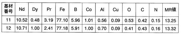
- Ten steps of NdFeB sintered magnet blocks (base materials) with different compositions were prepared by performing each step of orientation in the magnetic field, molding and sintering (FIG. 1). Of these, those with “(ratio)” in the “base number” column of FIG. 1 are base materials of comparative examples, and other base materials (base numbers 1 to 6) are base materials used in this example. It is.
- the composition shown in FIG. 1 is a chemical analysis value of the sintered body after sintering.
- the composition of the sintered body was changed by changing the composition of the strip cast alloy, the purity of the nitrogen gas used during jet mill grinding or the amount of oxygen added, and the type and amount of lubricant added before and after jet mill grinding. .
- the particle size of the fine powder after jet milling was adjusted so that the median value (D 50 ) of the particle size distribution measured by the laser diffraction method was 5 ⁇ m.
- All of these 10 types of sintered magnets have a composition close to that of NdFeB sintered magnets that are produced in large quantities by each magnet manufacturer as a material having the largest maximum magnetic energy product because the rare earth is composed only of Nd. However, among these magnets, those with the base material numbers 1 to 6 are produced by devising to minimize contamination by impurities.
- the substrate numbers “(ratio) 1 to (ratio) 4” have a composition close to that of commercially available products.
- the MR value indicates the amount of rare earth in the metallic state, and is calculated from the chemical analysis value of the sintered magnet. That is, the MR value is a value obtained by subtracting the amount of rare earth consumed (non-metalized) by oxygen, carbon, and nitrogen from the total amount of rare earth in the analysis value.
- these impurity elements are calculated assuming that they form a compound of R 2 O 3 , RC, and RN, respectively, with a rare earth (R represents a rare earth element).
- FIG. 2 shows the composition of the powder used in the experiment.
- the powder number with “(ratio)” is the powder of the comparative example.
- Powder numbers 1 to 6 and 13 to 15 were prepared by mixing powders of each component element.
- Dy powder of hydride DyH 3 was used.
- DyH 3 hydrogen is discharged out of the system at a temperature lower than the temperature at which grain boundary diffusion is started. Went.
- DyH 3 has a particle size of about 30 ⁇ m, and other component element powders have a particle size of 5 to 10 ⁇ m. Powder Nos.
- a cuboid sample was cut out from the 10 types of sintered body blocks in FIG. 1 so that the length direction was 7 mm ⁇ width 7 mm ⁇ thickness 3.5 mm and the thickness direction was the magnetization direction, and an experiment of grain boundary diffusion was performed. Powder coating was performed as follows. A 200 cm 3 plastic beaker was charged with 100 cm 3 of 1 mm diameter zirconia spheres, and 0.1 to 0.5 g of liquid paraffin was added and stirred. An NdFeB sintered magnet cuboid sample was put into this, and an adhesive layer (liquid paraffin) was applied to the surface of the cuboid sample by bringing the beaker into contact with a vibrator.
- an adhesive layer liquid paraffin
- the powder coating is limited to the magnetic pole surface. Since the present invention aims to be applied to a relatively large motor, it must be an effective technique for a magnet having a somewhat large magnetic pole area. However, the area of the magnetic pole is limited due to the convenience of the magnetization curve measuring instrument. Therefore, a sample with a relatively small magnetic pole area of 7 mm square is used, but by not applying powder on the side surface, the same situation as when conducting a grain boundary diffusion method on a sample with a large magnetic pole area is used. did.
- FIG. 3 shows the measurement results of the coercive force for the samples of various combinations of the base material, the powder, and the amount of the powder applied thus produced.
- samples within the scope of the present invention are 1.6 MA / m or more and samples with a coating amount of 7 mg / cm 2 or more by the Dy grain boundary diffusion method. It can be seen that it has a high coercive force of MA / m or more.
- the NdFeB sintered magnet base material does not contain Dy or Tb, and is a relatively thick 3.5 mm sample with a large magnetic pole area. There was no. It was also confirmed that a larger coercive force could be obtained when the applied powder contained metallic Tb (Sample No. 15).
- Example 2 The same experiment as in Example 1 was performed on a relatively thick substrate.
- the sample is a rectangular parallelepiped with a pole face of 7 mm on a side and a thickness of 5 mm or 6 mm (described in FIG. 4), and the magnetization direction is the thickness direction.
- the powder other than the magnetic pole surface is masked so that the powder containing Dy is applied only to the magnetic pole surface, and the powder is formed by barrel painting under the same conditions as in Example 1.
- Application was performed. Grain boundary diffusion treatment conditions and aging treatment conditions are the same as in Example 1.
- FIG. 4 shows the measurement results of magnetic properties of a sample manufactured under conditions within the scope of the present invention and a sample manufactured under conditions outside the scope of the present invention.
- H k / H cJ is represented by a symbol of SQ (Squerness).
- the NdFeB sintered magnet (sample number 20 to 25) produced by the method of the present invention has a high coercive force of 1.6 MA / m or more even when the thickness is 5 mm or 6 mm.
- the SQ value of these samples is over 90%.
- a large SQ value indicates that grain boundary diffusion has spread to the center of the sample.
- a sample with a thickness of 6 mm was coated with a powder containing Dy only on the magnetic pole surface, and a sample with a large SQ value was produced.
- the Dy in the powder applied to the surface was heated at 900 ° C. This indicates that 3 mm penetrated from both sides. This goes beyond the common sense of conventional grain boundary diffusion methods. This indicates that if the conditions of the present invention are satisfied, the grain boundary diffusion of Dy and Tb reaches deeper than the conventional common sense.
- Sample numbers “(ratio) 5 to (ratio) 8” shown as comparative examples are cases where the powder applied to the base material does not satisfy the conditions of the present invention.
- Sample numbers “(ratio) 9 to (ratio) ) 11 ” shows the experimental results when the NdFeB sintered magnet base material does not satisfy the conditions of the present invention. That is, sample numbers “(ratio) 5 to (ratio) 8” are cases where the Dy or / and Tb content in the powder applied to the substrate is low, and the coercive force and SQ achieved by the grain boundary diffusion treatment. The value is low.
- Sample numbers “(ratio) 9 to (ratio) 11” are samples in which the amount of rare earth in the metal state contained in the used NdFeB magnet base material is lower than 12.7 at%, and the sample subjected to grain boundary diffusion treatment Has a lower coercive force and SQ value than the sample prepared under the conditions of the present invention.
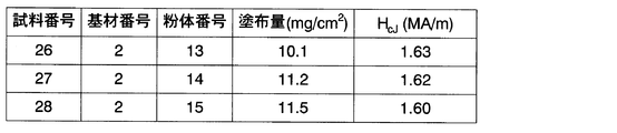
- Example 1 A powder containing no Al (powder numbers 13 to 15) was applied to the same substrate as in Example 1, and a grain boundary diffusion experiment was performed under the same conditions as in Example 1. The results are shown in FIG. When compared with the results of Example 1 and Example 3, it can be seen that in the present invention, a higher coercive force can be obtained when Al is contained in the applied powder. Al is presumed to work effectively to melt the applied powder.
- Example 1 the effectiveness of the present invention was shown when Dy and Tb were not included in the base material.
- the thickness of the sample is set to 3.5 mm, the powder coating conditions, the grain boundary diffusion treatment conditions, etc. These show the result of having experimented by producing a sample on the same conditions as Example 1.
- FIG. FIG. 7 shows the results of this example compared to the case where the substrate does not contain Dy. From FIG. 7, when a base material containing Dy is used in the present invention, the increase in coercive force of the base material itself by adding Dy to the base material is added to the increase in coercive force due to the grain boundary diffusion treatment.
- a part of the sample produced in the experiment of Example 1 was subjected to a corrosion resistance test.
- samples No. 3, 5, 6 as the first group samples No. 1, 13 as the second group and NdFeB sintered magnet samples without grain boundary diffusion treatment are left in 70 ° C steam saturated air Went.
- rust was observed in the second group of magnets, but no rust was observed in the first group of magnets.
- all magnets showed rust, but the degree of corrosion was milder in the first group of magnets than in the second group.
- the first group of magnets contains a total of 10% or more of Ni or / and Co in the powder applied for grain boundary diffusion, but the second group of magnets is not subjected to grain boundary diffusion treatment.
- the powder applied for grain boundary diffusion contains neither Ni nor Co.
- the surface layer after the grain boundary diffusion treatment serves as an anticorrosive film. I understand that it works. This anti-corrosion effect is not effective in a severe corrosive environment, but when a magnet is processed, stored or transported before surface treatment, rust is generated on the magnet surface during transportation, making it unusable as a product. It works to prevent this.
- the sample surface after grain boundary diffusion is smooth, the surface layer is strongly adhered to the substrate, and the powder layer applied to the substrate is It was confirmed that it melted during heating for grain boundary diffusion.
- the temperature and time of the grain boundary diffusion treatment were set to 900 ° C. and 3 hours, but it was confirmed that good results could be obtained by adjusting the time at a temperature between 800 ° C. and 1000 ° C. did.
Abstract
Description
(1) 特許文献1及び2に記載の方法は保磁力向上の効果が低い。
(2) スパッタリング法やイオンプレーティング法により磁石表面にDyやTbを含む成分を付着させる方法は、処理費が高価であり実用的でない。
(3) DyF3やDy2O3あるいはTbF3やTb2O3の粉末を磁石表面に塗布することによりDyやTbを含む成分を付着させる方法(特許文献3)は、処理費が安価である点では有利であるがこの方法により到達できる保磁力の値があまり大きくない。
(4) さらに特許文献4及び5の方法は、特許文献3や非特許文献4の方法に比べて特に利点がなく、やはり得られる保磁力の値が小さい。
a) 前記磁石基材中に含まれる金属状態の希土類量が12.7at%以上であり、
b) 前記層が粉末の堆積により形成される粉体層であり、
c) 前記粉体層が50mass%以上の金属状態のDy及び/又はTbを含有する、
ことを特徴とする。
「粉体層が50mass%以上の金属状態のDy及び/又はTb」は、粉体層が全て金属状態のDy及び/又はTbである場合、即ち粉体層が100mass%、Dy及び/又はTbから成る場合を含む。
「金属状態のDy及び/又はTb」とは、粒界拡散処理のために基材に塗布された粉体層のなかで、金属を構成しているDy及び/あるいはTbという意味である。ここにおいても金属は純金属、合金及び金属間化合物を含み、これらの希土類のフッ化物、炭化物、酸化物、窒化物は含まない。これらの希土類の水素化物、あるいはこれらの希土類を含む金属間化合物の水素化物は、金属間化合物の一種であり、これを構成する希土類は金属状態であるとみなす。これらの水素化物に含まれる水素はほとんど、DyやTbが基材に粒界拡散し始める前に、粉体層から離脱していく。したがって、粉体層の組成の計算には、水素化物中の水素は計算に入れないものとする。なお、組成を質量%で表現すると希土類と水素の原子量の差はきわめて大きいので、実際には組成計算に水素を入れるか入れないかによって計算値はほとんど変わらない。
磁石基材が3.5mm以上の厚さを持つ板状磁石基材であり、
前記板状磁石基材に含まれる金属状態の希土類量が12.7at%以上であり、
磁化曲線の角型性を示すSQ値が90%以上である、
ことを特徴とする。
ここでSQ値は、磁化曲線で磁化が最大値から10%低下したときの磁界の絶対値Hkを保磁力HcJで除した値Hk/HcJで定義される。SQ値が90%以上であるということは、磁石基材の中心付近にまでDy及び/又はTbが粒界拡散していることを意味している。このように3.5mm以上という厚い板状磁石基材を用いて90%以上という高いSQ値を得ることができたのは、磁石基材に含まれる金属状態の希土類の量を12.7at%以上にしたことで粒界拡散処理時にDy及び/又はTbが粒界に拡散しやすくなったことによる。
Claims (8)
- NdFeB焼結磁石基材の表面にDy及び/又はTbを含む層を形成した後に前記磁石基材の焼結温度以下の温度に加熱することにより前記層中のDy及び/又はTbを前記磁石基材の結晶粒界を通じて前記磁石基材内部に拡散させる粒界拡散処理を行うNdFeB焼結磁石の製造方法において、
a) 前記磁石基材中に含まれる金属状態の希土類量が12.7at%以上であり、
b) 前記層が粉末の堆積により形成される粉体層であり、
c) 前記粉体層が50mass%以上の金属状態のDy及び/又はTbを含有する、
ことを特徴とするNdFeB焼結磁石の製造方法。 - 前記粉体層の量が、前記磁石基材の表面1cm2あたり7mg以上であることを特徴とする請求項1に記載のNdFeB焼結磁石の製造方法。
- 前記粉体層がAlを1mass%以上含むことを特徴とする請求項1又は2に記載のNdFeB焼結磁石の製造方法。
- 前記粉体層がCo及び/又はNiを合計10mass%以上含むことを特徴とする請求項1~3のいずれかに記載のNdFeB焼結磁石の製造方法。
- 前記粉体層を粒界拡散処理中に溶融させることを特徴とする請求項1~4のいずれかに記載のNdFeB焼結磁石の製造方法。
- 粒界拡散法を用いた処理によりDy及び/又はTbを粒界拡散させたNdFeB焼結磁石において、
磁石基材が3.5mm以上の厚さを持つ板状磁石基材であり、
前記板状磁石基材に含まれる金属状態の希土類が12.7at%以上であり、
磁化曲線の角型性を示すSQ値が90%以上である、
ことを特徴とするNdFeB焼結磁石。 - 前記粒界付近及び前記表面付近にAlが含まれることを特徴とする請求項6に記載のNdFeB焼結磁石。
- 前記粒界付近及び前記表面付近にCo及び/又はNiが含まれることを特徴とする請求項6又は7に記載のNdFeB焼結磁石。
Priority Applications (4)
| Application Number | Priority Date | Filing Date | Title |
|---|---|---|---|
| EP09700197.8A EP2239747A4 (en) | 2008-01-11 | 2009-01-09 | PROCESS FOR PRODUCTION OF FRITTED MAGNETS NDFEB AND FRITTED MAGNETS NdFeB |
| CN200980101615.0A CN101911227B (zh) | 2008-01-11 | 2009-01-09 | NdFeB烧结磁体的制造方法和NdFeB烧结磁体 |
| US12/812,379 US8562756B2 (en) | 2008-01-11 | 2009-01-09 | NdFeB sintered magnet and method for producing the same |
| US13/778,324 US10854380B2 (en) | 2008-01-11 | 2013-02-27 | NdFeB sintered magnet and method for producing the same |
Applications Claiming Priority (2)
| Application Number | Priority Date | Filing Date | Title |
|---|---|---|---|
| JP2008-004845 | 2008-01-11 | ||
| JP2008004845A JP5328161B2 (ja) | 2008-01-11 | 2008-01-11 | NdFeB焼結磁石の製造方法及びNdFeB焼結磁石 |
Related Child Applications (2)
| Application Number | Title | Priority Date | Filing Date |
|---|---|---|---|
| US12/812,379 A-371-Of-International US8562756B2 (en) | 2008-01-11 | 2009-01-09 | NdFeB sintered magnet and method for producing the same |
| US13/778,324 Continuation US10854380B2 (en) | 2008-01-11 | 2013-02-27 | NdFeB sintered magnet and method for producing the same |
Publications (1)
| Publication Number | Publication Date |
|---|---|
| WO2009087975A1 true WO2009087975A1 (ja) | 2009-07-16 |
Family
ID=40853089
Family Applications (1)
| Application Number | Title | Priority Date | Filing Date |
|---|---|---|---|
| PCT/JP2009/000068 WO2009087975A1 (ja) | 2008-01-11 | 2009-01-09 | NdFeB焼結磁石の製造方法及びNdFeB焼結磁石 |
Country Status (5)
| Country | Link |
|---|---|
| US (2) | US8562756B2 (ja) |
| EP (1) | EP2239747A4 (ja) |
| JP (1) | JP5328161B2 (ja) |
| CN (3) | CN101911227B (ja) |
| WO (1) | WO2009087975A1 (ja) |
Cited By (8)
| Publication number | Priority date | Publication date | Assignee | Title |
|---|---|---|---|---|
| JP2011061038A (ja) * | 2009-09-10 | 2011-03-24 | Toyota Central R&D Labs Inc | 希土類磁石とその製造方法および磁石複合部材 |
| WO2012029748A1 (ja) * | 2010-08-31 | 2012-03-08 | 並木精密宝石株式会社 | R-Fe-B系希土類焼結磁石とその製造方法、製造装置、モータ又は発電機 |
| EP2650887A2 (en) | 2012-04-11 | 2013-10-16 | Shin-Etsu Chemical Co., Ltd. | Rare earth sintered magnet and making method |
| EP2555208A4 (en) * | 2010-03-30 | 2017-10-25 | TDK Corporation | Sintered magnet, motor, automobile, and method for producing sintered magnet |
| WO2018030187A1 (ja) * | 2016-08-08 | 2018-02-15 | 日立金属株式会社 | R-t-b系焼結磁石の製造方法 |
| CN107802186A (zh) * | 2016-09-09 | 2018-03-16 | 三星电子株式会社 | 烤箱 |
| CN108010705A (zh) * | 2017-11-29 | 2018-05-08 | 宁德市星宇科技有限公司 | 一种钕铁硼磁体的制备方法 |
| CN111937103A (zh) * | 2018-03-29 | 2020-11-13 | 日立金属株式会社 | R-t-b系烧结磁体的制造方法 |
Families Citing this family (41)
| Publication number | Priority date | Publication date | Assignee | Title |
|---|---|---|---|---|
| JP5328161B2 (ja) * | 2008-01-11 | 2013-10-30 | インターメタリックス株式会社 | NdFeB焼結磁石の製造方法及びNdFeB焼結磁石 |
| EP2453448A4 (en) | 2009-07-10 | 2014-08-06 | Intermetallics Co Ltd | FRYED NDFEB MAGNET AND MANUFACTURING METHOD THEREOF |
| JP5406112B2 (ja) | 2010-04-27 | 2014-02-05 | インターメタリックス株式会社 | 粒界拡散処理用塗布装置 |
| JP5854304B2 (ja) * | 2011-01-19 | 2016-02-09 | 日立金属株式会社 | R−t−b系焼結磁石の製造方法 |
| CN102184776B (zh) * | 2011-02-24 | 2012-11-14 | 中国计量学院 | 一种稀土配合物晶界改性烧结钕铁硼磁体的制备方法 |
| US20120299398A1 (en) * | 2011-05-23 | 2012-11-29 | Nikon Corporation | Motor, design method and manufacturing method of motor, stage device, and exposure apparatus |
| JP5572673B2 (ja) * | 2011-07-08 | 2014-08-13 | 昭和電工株式会社 | R−t−b系希土類焼結磁石用合金、r−t−b系希土類焼結磁石用合金の製造方法、r−t−b系希土類焼結磁石用合金材料、r−t−b系希土類焼結磁石、r−t−b系希土類焼結磁石の製造方法およびモーター |
| CN103650073B (zh) | 2011-12-27 | 2015-11-25 | 因太金属株式会社 | NdFeB系烧结磁体和该NdFeB系烧结磁体的制造方法 |
| EP2693450B1 (en) | 2011-12-27 | 2017-03-22 | Intermetallics Co., Ltd. | Sintered neodymium magnet |
| WO2013100011A1 (ja) | 2011-12-27 | 2013-07-04 | インターメタリックス株式会社 | NdFeB系焼結磁石 |
| JP5503086B2 (ja) * | 2011-12-27 | 2014-05-28 | インターメタリックス株式会社 | NdFeB系焼結磁石 |
| US9478332B2 (en) * | 2012-01-19 | 2016-10-25 | Hitachi Metals, Ltd. | Method for producing R-T-B sintered magnet |
| KR20150002638A (ko) * | 2012-03-30 | 2015-01-07 | 인터메탈릭스 가부시키가이샤 | NdFeB계 소결 자석 |
| JP6238444B2 (ja) * | 2013-01-07 | 2017-11-29 | 昭和電工株式会社 | R−t−b系希土類焼結磁石、r−t−b系希土類焼結磁石用合金およびその製造方法 |
| CN105144321B (zh) * | 2013-03-18 | 2017-12-22 | 因太金属株式会社 | RFeB系磁体制造方法、RFeB系磁体以及晶界扩散处理用涂布物 |
| JP5983598B2 (ja) * | 2013-12-27 | 2016-08-31 | トヨタ自動車株式会社 | 希土類磁石の製造方法 |
| KR101534717B1 (ko) * | 2013-12-31 | 2015-07-24 | 현대자동차 주식회사 | 희토류계 자석 제조 방법 |
| KR101548684B1 (ko) * | 2014-04-18 | 2015-09-11 | 고려대학교 산학협력단 | 희토류계 소결 자석의 제조방법 |
| JP2015228431A (ja) * | 2014-06-02 | 2015-12-17 | インターメタリックス株式会社 | RFeB系磁石及びRFeB系磁石の製造方法 |
| JP6500387B2 (ja) * | 2014-10-21 | 2019-04-17 | 日産自動車株式会社 | 高保磁力磁石の製造方法 |
| KR101624245B1 (ko) * | 2015-01-09 | 2016-05-26 | 현대자동차주식회사 | 희토류 영구 자석 및 그 제조방법 |
| US10217562B2 (en) * | 2015-02-27 | 2019-02-26 | Hitachi Metals, Ltd. | Method for manufacturing R-T-B based sintered magnet |
| CN105185498B (zh) * | 2015-08-28 | 2017-09-01 | 包头天和磁材技术有限责任公司 | 稀土永磁材料及其制造方法 |
| EP3182423B1 (en) * | 2015-12-18 | 2019-03-20 | JL Mag Rare-Earth Co., Ltd. | Neodymium iron boron magnet and preparation method thereof |
| CN105761861B (zh) * | 2016-05-10 | 2019-03-12 | 江西金力永磁科技股份有限公司 | 一种钕铁硼磁体及其制备方法 |
| CN105632748B (zh) * | 2015-12-25 | 2019-01-11 | 宁波韵升股份有限公司 | 一种提高烧结钕铁硼薄片磁体磁性能的方法 |
| CN106935390B (zh) * | 2015-12-31 | 2020-03-27 | 厦门钨业股份有限公司 | 一种稀土烧结磁铁的表面处理方法 |
| JP6645219B2 (ja) * | 2016-02-01 | 2020-02-14 | Tdk株式会社 | R−t−b系焼結磁石用合金、及びr−t−b系焼結磁石 |
| JP6743549B2 (ja) | 2016-07-25 | 2020-08-19 | Tdk株式会社 | R−t−b系焼結磁石 |
| CN106847494B (zh) * | 2017-01-13 | 2018-08-24 | 中国科学院上海应用物理研究所 | 高性能永磁体制备方法及含该永磁体的真空波荡器磁结构 |
| CN110168680B (zh) * | 2017-01-26 | 2021-10-22 | 日产自动车株式会社 | 烧结磁体的制造方法 |
| CN108242336B (zh) * | 2017-12-25 | 2019-12-03 | 江苏大学 | 一种高性能低成本复合磁体的制备方法 |
| JP7314513B2 (ja) * | 2018-07-09 | 2023-07-26 | 大同特殊鋼株式会社 | RFeB系焼結磁石 |
| US11527340B2 (en) * | 2018-07-09 | 2022-12-13 | Daido Steel Co., Ltd. | RFeB-based sintered magnet |
| CN108962582B (zh) * | 2018-07-20 | 2020-07-07 | 烟台首钢磁性材料股份有限公司 | 一种钕铁硼磁体矫顽力提升方法 |
| CN108831655B (zh) * | 2018-07-20 | 2020-02-07 | 烟台首钢磁性材料股份有限公司 | 一种提高钕铁硼烧结永磁体矫顽力的方法 |
| JP7167673B2 (ja) * | 2018-12-03 | 2022-11-09 | Tdk株式会社 | R‐t‐b系永久磁石の製造方法 |
| CN110911151B (zh) * | 2019-11-29 | 2021-08-06 | 烟台首钢磁性材料股份有限公司 | 一种提高钕铁硼烧结永磁体矫顽力的方法 |
| CN111326307B (zh) * | 2020-03-17 | 2021-12-28 | 宁波金鸡强磁股份有限公司 | 一种渗透磁体用的涂覆材料及高矫顽力钕铁硼磁体的制备方法 |
| CN112017835B (zh) * | 2020-08-20 | 2023-03-17 | 合肥工业大学 | 一种低重稀土高矫顽力烧结钕铁硼磁体及其制备方法 |
| CN112768168B (zh) * | 2020-12-25 | 2023-05-30 | 福建省长汀金龙稀土有限公司 | 一种钕铁硼材料及其制备方法 |
Citations (9)
| Publication number | Priority date | Publication date | Assignee | Title |
|---|---|---|---|---|
| JPS6274048A (ja) | 1985-09-27 | 1987-04-04 | Sumitomo Special Metals Co Ltd | 永久磁石材料及びその製造方法 |
| JPH01117303A (ja) | 1987-10-30 | 1989-05-10 | Taiyo Yuden Co Ltd | 永久磁石 |
| JP2004359873A (ja) | 2003-06-06 | 2004-12-24 | Inter Metallics Kk | 粘着層形成方法 |
| WO2006043348A1 (ja) | 2004-10-19 | 2006-04-27 | Shin-Etsu Chemical Co., Ltd. | 希土類永久磁石材料の製造方法 |
| JP2007258455A (ja) * | 2006-03-23 | 2007-10-04 | Hitachi Metals Ltd | R−Fe−B系希土類焼結磁石およびその製造方法 |
| JP2007287874A (ja) | 2006-04-14 | 2007-11-01 | Shin Etsu Chem Co Ltd | 希土類永久磁石材料の製造方法 |
| JP2007287875A (ja) | 2006-04-14 | 2007-11-01 | Shin Etsu Chem Co Ltd | 希土類永久磁石材料の製造方法 |
| WO2008032426A1 (en) * | 2006-09-15 | 2008-03-20 | Intermetallics Co., Ltd. | PROCESS FOR PRODUCING SINTERED NdFeB MAGNET |
| WO2008139690A1 (ja) * | 2007-05-01 | 2008-11-20 | Intermetallics Co., Ltd. | NdFeB系焼結磁石製造方法 |
Family Cites Families (33)
| Publication number | Priority date | Publication date | Assignee | Title |
|---|---|---|---|---|
| US716A (en) * | 1838-04-28 | Henry barnes | ||
| JPH0742553B2 (ja) | 1986-02-18 | 1995-05-10 | 住友特殊金属株式会社 | 永久磁石材料及びその製造方法 |
| JPH0696928A (ja) * | 1992-06-30 | 1994-04-08 | Aichi Steel Works Ltd | 希土類焼結磁石及びその製造方法 |
| JPH09232173A (ja) * | 1996-02-27 | 1997-09-05 | Hitachi Metals Ltd | 希土類磁石の製造方法および希土類磁石 |
| JP2000234151A (ja) * | 1998-12-15 | 2000-08-29 | Shin Etsu Chem Co Ltd | R−Fe−B系希土類永久磁石材料 |
| CN1187152C (zh) | 1999-03-03 | 2005-02-02 | 株式会社新王磁材 | 稀土磁铁烧结用烧结箱及用该箱烧结处理的稀土磁铁制法 |
| US7244318B2 (en) * | 2001-01-30 | 2007-07-17 | Neomax Co., Ltd. | Method for preparation of permanent magnet |
| JP3897724B2 (ja) * | 2003-03-31 | 2007-03-28 | 独立行政法人科学技術振興機構 | 超小型製品用の微小、高性能焼結希土類磁石の製造方法 |
| JP2005011973A (ja) | 2003-06-18 | 2005-01-13 | Japan Science & Technology Agency | 希土類−鉄−ホウ素系磁石及びその製造方法 |
| WO2005001855A1 (ja) * | 2003-06-27 | 2005-01-06 | Tdk Corporation | R-t-b系永久磁石 |
| JP4879503B2 (ja) | 2004-04-07 | 2012-02-22 | 昭和電工株式会社 | R−t−b系焼結磁石用合金塊、その製造法および磁石 |
| CN100547700C (zh) | 2004-04-07 | 2009-10-07 | 昭和电工株式会社 | 用于r-t-b型烧结磁体的合金块其制造方法和磁体 |
| TWI302712B (en) | 2004-12-16 | 2008-11-01 | Japan Science & Tech Agency | Nd-fe-b base magnet including modified grain boundaries and method for manufacturing the same |
| JP4543940B2 (ja) | 2005-01-25 | 2010-09-15 | Tdk株式会社 | R−t−b系焼結磁石の製造方法 |
| JP5339722B2 (ja) * | 2005-03-18 | 2013-11-13 | 株式会社アルバック | 成膜方法及び成膜装置並びに永久磁石及び永久磁石の製造方法 |
| JP4702548B2 (ja) | 2005-03-23 | 2011-06-15 | 信越化学工業株式会社 | 傾斜機能性希土類永久磁石 |
| MY142131A (en) | 2005-03-23 | 2010-09-30 | Shinetsu Chemical Co | Functionally graded rare earth permanent magnet |
| MY142088A (en) * | 2005-03-23 | 2010-09-15 | Shinetsu Chemical Co | Rare earth permanent magnet |
| WO2006112403A1 (ja) * | 2005-04-15 | 2006-10-26 | Hitachi Metals, Ltd. | 希土類焼結磁石とその製造方法 |
| CN100356487C (zh) | 2005-06-06 | 2007-12-19 | 浙江大学 | 一种烧结钕铁硼磁体的制备方法 |
| JP4530360B2 (ja) * | 2005-06-27 | 2010-08-25 | 株式会社トンボ鉛筆 | 感圧転写修正テープ及びそれに用いるインク |
| JP4656325B2 (ja) | 2005-07-22 | 2011-03-23 | 信越化学工業株式会社 | 希土類永久磁石、その製造方法、並びに永久磁石回転機 |
| US7559996B2 (en) * | 2005-07-22 | 2009-07-14 | Shin-Etsu Chemical Co., Ltd. | Rare earth permanent magnet, making method, and permanent magnet rotary machine |
| EP1981043B1 (en) * | 2006-01-31 | 2015-08-12 | Hitachi Metals, Limited | R-Fe-B RARE-EARTH SINTERED MAGNET AND PROCESS FOR PRODUCING THE SAME |
| JP2007329250A (ja) | 2006-06-07 | 2007-12-20 | Ulvac Japan Ltd | 永久磁石及び永久磁石の製造方法 |
| CN101506919B (zh) * | 2006-08-23 | 2012-10-31 | 株式会社爱发科 | 永磁铁以及永磁铁的制造方法 |
| JP4840606B2 (ja) | 2006-11-17 | 2011-12-21 | 信越化学工業株式会社 | 希土類永久磁石の製造方法 |
| MY149353A (en) * | 2007-03-16 | 2013-08-30 | Shinetsu Chemical Co | Rare earth permanent magnet and its preparations |
| JP5274781B2 (ja) | 2007-03-22 | 2013-08-28 | 昭和電工株式会社 | R−t−b系合金及びr−t−b系合金の製造方法、r−t−b系希土類永久磁石用微粉、r−t−b系希土類永久磁石 |
| EP2133891B1 (en) * | 2007-03-30 | 2017-03-08 | TDK Corporation | Process for producing magnet |
| US20100230013A1 (en) | 2007-12-13 | 2010-09-16 | Showa Denko K.K. | R-t-b alloy, process for production of r-t-b alloy, fine powder for r-t-b rare earth permanent magnets, and r-t-b rare earth permanent magnet |
| JP5328161B2 (ja) * | 2008-01-11 | 2013-10-30 | インターメタリックス株式会社 | NdFeB焼結磁石の製造方法及びNdFeB焼結磁石 |
| EP2453448A4 (en) | 2009-07-10 | 2014-08-06 | Intermetallics Co Ltd | FRYED NDFEB MAGNET AND MANUFACTURING METHOD THEREOF |
-
2008
- 2008-01-11 JP JP2008004845A patent/JP5328161B2/ja active Active
-
2009
- 2009-01-09 EP EP09700197.8A patent/EP2239747A4/en not_active Withdrawn
- 2009-01-09 US US12/812,379 patent/US8562756B2/en active Active
- 2009-01-09 WO PCT/JP2009/000068 patent/WO2009087975A1/ja active Application Filing
- 2009-01-09 CN CN200980101615.0A patent/CN101911227B/zh active Active
- 2009-01-09 CN CN2013102617302A patent/CN103354167A/zh active Pending
- 2009-01-09 CN CN201310571585.8A patent/CN103646740A/zh active Pending
-
2013
- 2013-02-27 US US13/778,324 patent/US10854380B2/en active Active
Patent Citations (9)
| Publication number | Priority date | Publication date | Assignee | Title |
|---|---|---|---|---|
| JPS6274048A (ja) | 1985-09-27 | 1987-04-04 | Sumitomo Special Metals Co Ltd | 永久磁石材料及びその製造方法 |
| JPH01117303A (ja) | 1987-10-30 | 1989-05-10 | Taiyo Yuden Co Ltd | 永久磁石 |
| JP2004359873A (ja) | 2003-06-06 | 2004-12-24 | Inter Metallics Kk | 粘着層形成方法 |
| WO2006043348A1 (ja) | 2004-10-19 | 2006-04-27 | Shin-Etsu Chemical Co., Ltd. | 希土類永久磁石材料の製造方法 |
| JP2007258455A (ja) * | 2006-03-23 | 2007-10-04 | Hitachi Metals Ltd | R−Fe−B系希土類焼結磁石およびその製造方法 |
| JP2007287874A (ja) | 2006-04-14 | 2007-11-01 | Shin Etsu Chem Co Ltd | 希土類永久磁石材料の製造方法 |
| JP2007287875A (ja) | 2006-04-14 | 2007-11-01 | Shin Etsu Chem Co Ltd | 希土類永久磁石材料の製造方法 |
| WO2008032426A1 (en) * | 2006-09-15 | 2008-03-20 | Intermetallics Co., Ltd. | PROCESS FOR PRODUCING SINTERED NdFeB MAGNET |
| WO2008139690A1 (ja) * | 2007-05-01 | 2008-11-20 | Intermetallics Co., Ltd. | NdFeB系焼結磁石製造方法 |
Non-Patent Citations (6)
Cited By (12)
| Publication number | Priority date | Publication date | Assignee | Title |
|---|---|---|---|---|
| JP2011061038A (ja) * | 2009-09-10 | 2011-03-24 | Toyota Central R&D Labs Inc | 希土類磁石とその製造方法および磁石複合部材 |
| EP2555208A4 (en) * | 2010-03-30 | 2017-10-25 | TDK Corporation | Sintered magnet, motor, automobile, and method for producing sintered magnet |
| WO2012029748A1 (ja) * | 2010-08-31 | 2012-03-08 | 並木精密宝石株式会社 | R-Fe-B系希土類焼結磁石とその製造方法、製造装置、モータ又は発電機 |
| EP2650887A2 (en) | 2012-04-11 | 2013-10-16 | Shin-Etsu Chemical Co., Ltd. | Rare earth sintered magnet and making method |
| US10074477B2 (en) | 2012-04-11 | 2018-09-11 | Shin-Etsu Chemical Co., Ltd. | Rare earth sintered magnet and making method |
| WO2018030187A1 (ja) * | 2016-08-08 | 2018-02-15 | 日立金属株式会社 | R-t-b系焼結磁石の製造方法 |
| JPWO2018030187A1 (ja) * | 2016-08-08 | 2018-08-16 | 日立金属株式会社 | R−t−b系焼結磁石の製造方法 |
| US11062844B2 (en) | 2016-08-08 | 2021-07-13 | Hitachi Metals, Ltd. | Method of producing R-T-B sintered magnet |
| CN107802186A (zh) * | 2016-09-09 | 2018-03-16 | 三星电子株式会社 | 烤箱 |
| CN108010705A (zh) * | 2017-11-29 | 2018-05-08 | 宁德市星宇科技有限公司 | 一种钕铁硼磁体的制备方法 |
| CN108010705B (zh) * | 2017-11-29 | 2020-08-04 | 宁德市星宇科技有限公司 | 一种钕铁硼磁体的制备方法 |
| CN111937103A (zh) * | 2018-03-29 | 2020-11-13 | 日立金属株式会社 | R-t-b系烧结磁体的制造方法 |
Also Published As
| Publication number | Publication date |
|---|---|
| JP5328161B2 (ja) | 2013-10-30 |
| US10854380B2 (en) | 2020-12-01 |
| CN103354167A (zh) | 2013-10-16 |
| CN103646740A (zh) | 2014-03-19 |
| EP2239747A4 (en) | 2015-08-12 |
| US20130169394A1 (en) | 2013-07-04 |
| JP2009170541A (ja) | 2009-07-30 |
| CN101911227A (zh) | 2010-12-08 |
| EP2239747A1 (en) | 2010-10-13 |
| CN101911227B (zh) | 2014-01-15 |
| US20100282371A1 (en) | 2010-11-11 |
| US8562756B2 (en) | 2013-10-22 |
Similar Documents
| Publication | Publication Date | Title |
|---|---|---|
| JP5328161B2 (ja) | NdFeB焼結磁石の製造方法及びNdFeB焼結磁石 | |
| JP5363314B2 (ja) | NdFeB系焼結磁石製造方法 | |
| KR101447301B1 (ko) | NdFeB 소결자석의 제조방법 | |
| JP6005768B2 (ja) | NdFeB焼結磁石及びその製造方法 | |
| TWI509642B (zh) | Rare earth permanent magnet and its manufacturing method | |
| KR101624245B1 (ko) | 희토류 영구 자석 및 그 제조방법 | |
| EP1970924B1 (en) | Rare earth permanent magnets and their preparation | |
| JP5057111B2 (ja) | 希土類磁石の製造方法 | |
| EP2302646B1 (en) | R-t-cu-mn-b type sintered magnet | |
| JP4677942B2 (ja) | R−Fe−B系希土類焼結磁石の製造方法 | |
| CN108417334B (zh) | R-t-b系烧结磁铁 | |
| US20170250015A1 (en) | R-t-b based permanent magnet | |
| JP5209349B2 (ja) | NdFeB焼結磁石の製造方法 | |
| JP5348124B2 (ja) | R−Fe−B系希土類焼結磁石の製造方法およびその方法によって製造された希土類焼結磁石 | |
| JP5643355B2 (ja) | NdFeB焼結磁石の製造方法 | |
| CN112136192A (zh) | 稀土烧结永磁体的制造方法 | |
| JP2005325450A (ja) | 磁性材料の製造方法、防錆層付き磁性材料粉末及びそれを用いたボンド磁石 | |
| JPH07201623A (ja) | 焼結磁石およびその製造方法 |
Legal Events
| Date | Code | Title | Description |
|---|---|---|---|
| WWE | Wipo information: entry into national phase |
Ref document number: 200980101615.0 Country of ref document: CN |
|
| 121 | Ep: the epo has been informed by wipo that ep was designated in this application |
Ref document number: 09700197 Country of ref document: EP Kind code of ref document: A1 |
|
| WWE | Wipo information: entry into national phase |
Ref document number: 12812379 Country of ref document: US |
|
| NENP | Non-entry into the national phase |
Ref country code: DE |
|
| REEP | Request for entry into the european phase |
Ref document number: 2009700197 Country of ref document: EP |
|
| WWE | Wipo information: entry into national phase |
Ref document number: 2009700197 Country of ref document: EP |
|
| WWE | Wipo information: entry into national phase |
Ref document number: 5479/DELNP/2010 Country of ref document: IN |