US9831043B2 - Electrochemical energy storage systems and methods - Google Patents
Electrochemical energy storage systems and methods Download PDFInfo
- Publication number
- US9831043B2 US9831043B2 US13/229,479 US201113229479A US9831043B2 US 9831043 B2 US9831043 B2 US 9831043B2 US 201113229479 A US201113229479 A US 201113229479A US 9831043 B2 US9831043 B2 US 9831043B2
- Authority
- US
- United States
- Prior art keywords
- electrode
- rod
- electrodes
- plate
- electrode array
- Prior art date
- Legal status (The legal status is an assumption and is not a legal conclusion. Google has not performed a legal analysis and makes no representation as to the accuracy of the status listed.)
- Active, expires
Links
Images


Classifications
-
- H—ELECTRICITY
- H01—ELECTRIC ELEMENTS
- H01G—CAPACITORS; CAPACITORS, RECTIFIERS, DETECTORS, SWITCHING DEVICES, LIGHT-SENSITIVE OR TEMPERATURE-SENSITIVE DEVICES OF THE ELECTROLYTIC TYPE
- H01G11/00—Hybrid capacitors, i.e. capacitors having different positive and negative electrodes; Electric double-layer [EDL] capacitors; Processes for the manufacture thereof or of parts thereof
- H01G11/22—Electrodes
- H01G11/26—Electrodes characterised by their structure, e.g. multi-layered, porosity or surface features
-
- H—ELECTRICITY
- H01—ELECTRIC ELEMENTS
- H01M—PROCESSES OR MEANS, e.g. BATTERIES, FOR THE DIRECT CONVERSION OF CHEMICAL ENERGY INTO ELECTRICAL ENERGY
- H01M4/00—Electrodes
-
- H—ELECTRICITY
- H01—ELECTRIC ELEMENTS
- H01G—CAPACITORS; CAPACITORS, RECTIFIERS, DETECTORS, SWITCHING DEVICES, LIGHT-SENSITIVE OR TEMPERATURE-SENSITIVE DEVICES OF THE ELECTROLYTIC TYPE
- H01G11/00—Hybrid capacitors, i.e. capacitors having different positive and negative electrodes; Electric double-layer [EDL] capacitors; Processes for the manufacture thereof or of parts thereof
- H01G11/02—Hybrid capacitors, i.e. capacitors having different positive and negative electrodes; Electric double-layer [EDL] capacitors; Processes for the manufacture thereof or of parts thereof using combined reduction-oxidation reactions, e.g. redox arrangement or solion
-
- H—ELECTRICITY
- H01—ELECTRIC ELEMENTS
- H01G—CAPACITORS; CAPACITORS, RECTIFIERS, DETECTORS, SWITCHING DEVICES, LIGHT-SENSITIVE OR TEMPERATURE-SENSITIVE DEVICES OF THE ELECTROLYTIC TYPE
- H01G11/00—Hybrid capacitors, i.e. capacitors having different positive and negative electrodes; Electric double-layer [EDL] capacitors; Processes for the manufacture thereof or of parts thereof
- H01G11/10—Multiple hybrid or EDL capacitors, e.g. arrays or modules
-
- H—ELECTRICITY
- H01—ELECTRIC ELEMENTS
- H01G—CAPACITORS; CAPACITORS, RECTIFIERS, DETECTORS, SWITCHING DEVICES, LIGHT-SENSITIVE OR TEMPERATURE-SENSITIVE DEVICES OF THE ELECTROLYTIC TYPE
- H01G11/00—Hybrid capacitors, i.e. capacitors having different positive and negative electrodes; Electric double-layer [EDL] capacitors; Processes for the manufacture thereof or of parts thereof
- H01G11/14—Arrangements or processes for adjusting or protecting hybrid or EDL capacitors
- H01G11/18—Arrangements or processes for adjusting or protecting hybrid or EDL capacitors against thermal overloads, e.g. heating, cooling or ventilating
-
- H—ELECTRICITY
- H01—ELECTRIC ELEMENTS
- H01G—CAPACITORS; CAPACITORS, RECTIFIERS, DETECTORS, SWITCHING DEVICES, LIGHT-SENSITIVE OR TEMPERATURE-SENSITIVE DEVICES OF THE ELECTROLYTIC TYPE
- H01G11/00—Hybrid capacitors, i.e. capacitors having different positive and negative electrodes; Electric double-layer [EDL] capacitors; Processes for the manufacture thereof or of parts thereof
- H01G11/22—Electrodes
- H01G11/30—Electrodes characterised by their material
- H01G11/46—Metal oxides
-
- H—ELECTRICITY
- H01—ELECTRIC ELEMENTS
- H01G—CAPACITORS; CAPACITORS, RECTIFIERS, DETECTORS, SWITCHING DEVICES, LIGHT-SENSITIVE OR TEMPERATURE-SENSITIVE DEVICES OF THE ELECTROLYTIC TYPE
- H01G11/00—Hybrid capacitors, i.e. capacitors having different positive and negative electrodes; Electric double-layer [EDL] capacitors; Processes for the manufacture thereof or of parts thereof
- H01G11/54—Electrolytes
- H01G11/56—Solid electrolytes, e.g. gels; Additives therein
-
- H—ELECTRICITY
- H01—ELECTRIC ELEMENTS
- H01G—CAPACITORS; CAPACITORS, RECTIFIERS, DETECTORS, SWITCHING DEVICES, LIGHT-SENSITIVE OR TEMPERATURE-SENSITIVE DEVICES OF THE ELECTROLYTIC TYPE
- H01G11/00—Hybrid capacitors, i.e. capacitors having different positive and negative electrodes; Electric double-layer [EDL] capacitors; Processes for the manufacture thereof or of parts thereof
- H01G11/66—Current collectors
- H01G11/70—Current collectors characterised by their structure
-
- H—ELECTRICITY
- H01—ELECTRIC ELEMENTS
- H01G—CAPACITORS; CAPACITORS, RECTIFIERS, DETECTORS, SWITCHING DEVICES, LIGHT-SENSITIVE OR TEMPERATURE-SENSITIVE DEVICES OF THE ELECTROLYTIC TYPE
- H01G2/00—Details of capacitors not covered by a single one of groups H01G4/00-H01G11/00
- H01G2/08—Cooling arrangements; Heating arrangements; Ventilating arrangements
-
- H—ELECTRICITY
- H01—ELECTRIC ELEMENTS
- H01G—CAPACITORS; CAPACITORS, RECTIFIERS, DETECTORS, SWITCHING DEVICES, LIGHT-SENSITIVE OR TEMPERATURE-SENSITIVE DEVICES OF THE ELECTROLYTIC TYPE
- H01G9/00—Electrolytic capacitors, rectifiers, detectors, switching devices, light-sensitive or temperature-sensitive devices; Processes of their manufacture
- H01G9/0003—Protection against electric or thermal overload; cooling arrangements; means for avoiding the formation of cathode films
-
- H—ELECTRICITY
- H01—ELECTRIC ELEMENTS
- H01G—CAPACITORS; CAPACITORS, RECTIFIERS, DETECTORS, SWITCHING DEVICES, LIGHT-SENSITIVE OR TEMPERATURE-SENSITIVE DEVICES OF THE ELECTROLYTIC TYPE
- H01G9/00—Electrolytic capacitors, rectifiers, detectors, switching devices, light-sensitive or temperature-sensitive devices; Processes of their manufacture
- H01G9/0029—Processes of manufacture
-
- H—ELECTRICITY
- H01—ELECTRIC ELEMENTS
- H01G—CAPACITORS; CAPACITORS, RECTIFIERS, DETECTORS, SWITCHING DEVICES, LIGHT-SENSITIVE OR TEMPERATURE-SENSITIVE DEVICES OF THE ELECTROLYTIC TYPE
- H01G9/00—Electrolytic capacitors, rectifiers, detectors, switching devices, light-sensitive or temperature-sensitive devices; Processes of their manufacture
- H01G9/004—Details
- H01G9/04—Electrodes or formation of dielectric layers thereon
- H01G9/048—Electrodes or formation of dielectric layers thereon characterised by their structure
-
- H—ELECTRICITY
- H01—ELECTRIC ELEMENTS
- H01G—CAPACITORS; CAPACITORS, RECTIFIERS, DETECTORS, SWITCHING DEVICES, LIGHT-SENSITIVE OR TEMPERATURE-SENSITIVE DEVICES OF THE ELECTROLYTIC TYPE
- H01G9/00—Electrolytic capacitors, rectifiers, detectors, switching devices, light-sensitive or temperature-sensitive devices; Processes of their manufacture
- H01G9/004—Details
- H01G9/07—Dielectric layers
-
- H—ELECTRICITY
- H01—ELECTRIC ELEMENTS
- H01M—PROCESSES OR MEANS, e.g. BATTERIES, FOR THE DIRECT CONVERSION OF CHEMICAL ENERGY INTO ELECTRICAL ENERGY
- H01M10/00—Secondary cells; Manufacture thereof
- H01M10/04—Construction or manufacture in general
-
- H—ELECTRICITY
- H01—ELECTRIC ELEMENTS
- H01M—PROCESSES OR MEANS, e.g. BATTERIES, FOR THE DIRECT CONVERSION OF CHEMICAL ENERGY INTO ELECTRICAL ENERGY
- H01M10/00—Secondary cells; Manufacture thereof
- H01M10/05—Accumulators with non-aqueous electrolyte
- H01M10/056—Accumulators with non-aqueous electrolyte characterised by the materials used as electrolytes, e.g. mixed inorganic/organic electrolytes
- H01M10/0564—Accumulators with non-aqueous electrolyte characterised by the materials used as electrolytes, e.g. mixed inorganic/organic electrolytes the electrolyte being constituted of organic materials only
- H01M10/0566—Liquid materials
-
- H—ELECTRICITY
- H01—ELECTRIC ELEMENTS
- H01M—PROCESSES OR MEANS, e.g. BATTERIES, FOR THE DIRECT CONVERSION OF CHEMICAL ENERGY INTO ELECTRICAL ENERGY
- H01M10/00—Secondary cells; Manufacture thereof
- H01M10/05—Accumulators with non-aqueous electrolyte
- H01M10/058—Construction or manufacture
-
- H—ELECTRICITY
- H01—ELECTRIC ELEMENTS
- H01M—PROCESSES OR MEANS, e.g. BATTERIES, FOR THE DIRECT CONVERSION OF CHEMICAL ENERGY INTO ELECTRICAL ENERGY
- H01M10/00—Secondary cells; Manufacture thereof
- H01M10/60—Heating or cooling; Temperature control
- H01M10/65—Means for temperature control structurally associated with the cells
- H01M10/655—Solid structures for heat exchange or heat conduction
- H01M10/6554—Rods or plates
-
- H—ELECTRICITY
- H01—ELECTRIC ELEMENTS
- H01M—PROCESSES OR MEANS, e.g. BATTERIES, FOR THE DIRECT CONVERSION OF CHEMICAL ENERGY INTO ELECTRICAL ENERGY
- H01M12/00—Hybrid cells; Manufacture thereof
- H01M12/02—Details
-
- H—ELECTRICITY
- H01—ELECTRIC ELEMENTS
- H01M—PROCESSES OR MEANS, e.g. BATTERIES, FOR THE DIRECT CONVERSION OF CHEMICAL ENERGY INTO ELECTRICAL ENERGY
- H01M12/00—Hybrid cells; Manufacture thereof
- H01M12/04—Hybrid cells; Manufacture thereof composed of a half-cell of the fuel-cell type and of a half-cell of the primary-cell type
- H01M12/06—Hybrid cells; Manufacture thereof composed of a half-cell of the fuel-cell type and of a half-cell of the primary-cell type with one metallic and one gaseous electrode
- H01M12/065—Hybrid cells; Manufacture thereof composed of a half-cell of the fuel-cell type and of a half-cell of the primary-cell type with one metallic and one gaseous electrode with plate-like electrodes or stacks of plate-like electrodes
-
- H—ELECTRICITY
- H01—ELECTRIC ELEMENTS
- H01M—PROCESSES OR MEANS, e.g. BATTERIES, FOR THE DIRECT CONVERSION OF CHEMICAL ENERGY INTO ELECTRICAL ENERGY
- H01M4/00—Electrodes
- H01M4/02—Electrodes composed of, or comprising, active material
-
- H—ELECTRICITY
- H01—ELECTRIC ELEMENTS
- H01M—PROCESSES OR MEANS, e.g. BATTERIES, FOR THE DIRECT CONVERSION OF CHEMICAL ENERGY INTO ELECTRICAL ENERGY
- H01M4/00—Electrodes
- H01M4/02—Electrodes composed of, or comprising, active material
- H01M4/04—Processes of manufacture in general
-
- H—ELECTRICITY
- H01—ELECTRIC ELEMENTS
- H01M—PROCESSES OR MEANS, e.g. BATTERIES, FOR THE DIRECT CONVERSION OF CHEMICAL ENERGY INTO ELECTRICAL ENERGY
- H01M4/00—Electrodes
- H01M4/02—Electrodes composed of, or comprising, active material
- H01M4/64—Carriers or collectors
- H01M4/66—Selection of materials
- H01M4/661—Metal or alloys, e.g. alloy coatings
-
- H—ELECTRICITY
- H01—ELECTRIC ELEMENTS
- H01M—PROCESSES OR MEANS, e.g. BATTERIES, FOR THE DIRECT CONVERSION OF CHEMICAL ENERGY INTO ELECTRICAL ENERGY
- H01M4/00—Electrodes
- H01M4/02—Electrodes composed of, or comprising, active material
- H01M4/64—Carriers or collectors
- H01M4/66—Selection of materials
- H01M4/663—Selection of materials containing carbon or carbonaceous materials as conductive part, e.g. graphite, carbon fibres
-
- H—ELECTRICITY
- H01—ELECTRIC ELEMENTS
- H01M—PROCESSES OR MEANS, e.g. BATTERIES, FOR THE DIRECT CONVERSION OF CHEMICAL ENERGY INTO ELECTRICAL ENERGY
- H01M4/00—Electrodes
- H01M4/02—Electrodes composed of, or comprising, active material
- H01M4/64—Carriers or collectors
- H01M4/66—Selection of materials
- H01M4/664—Ceramic materials
-
- H—ELECTRICITY
- H01—ELECTRIC ELEMENTS
- H01M—PROCESSES OR MEANS, e.g. BATTERIES, FOR THE DIRECT CONVERSION OF CHEMICAL ENERGY INTO ELECTRICAL ENERGY
- H01M4/00—Electrodes
- H01M4/02—Electrodes composed of, or comprising, active material
- H01M4/64—Carriers or collectors
- H01M4/70—Carriers or collectors characterised by shape or form
-
- H—ELECTRICITY
- H01—ELECTRIC ELEMENTS
- H01M—PROCESSES OR MEANS, e.g. BATTERIES, FOR THE DIRECT CONVERSION OF CHEMICAL ENERGY INTO ELECTRICAL ENERGY
- H01M4/00—Electrodes
- H01M4/86—Inert electrodes with catalytic activity, e.g. for fuel cells
-
- H—ELECTRICITY
- H01—ELECTRIC ELEMENTS
- H01M—PROCESSES OR MEANS, e.g. BATTERIES, FOR THE DIRECT CONVERSION OF CHEMICAL ENERGY INTO ELECTRICAL ENERGY
- H01M4/00—Electrodes
- H01M4/86—Inert electrodes with catalytic activity, e.g. for fuel cells
- H01M4/8605—Porous electrodes
-
- H—ELECTRICITY
- H01—ELECTRIC ELEMENTS
- H01M—PROCESSES OR MEANS, e.g. BATTERIES, FOR THE DIRECT CONVERSION OF CHEMICAL ENERGY INTO ELECTRICAL ENERGY
- H01M4/00—Electrodes
- H01M4/86—Inert electrodes with catalytic activity, e.g. for fuel cells
- H01M4/88—Processes of manufacture
-
- H—ELECTRICITY
- H01—ELECTRIC ELEMENTS
- H01M—PROCESSES OR MEANS, e.g. BATTERIES, FOR THE DIRECT CONVERSION OF CHEMICAL ENERGY INTO ELECTRICAL ENERGY
- H01M6/00—Primary cells; Manufacture thereof
- H01M6/02—Details
-
- H—ELECTRICITY
- H01—ELECTRIC ELEMENTS
- H01M—PROCESSES OR MEANS, e.g. BATTERIES, FOR THE DIRECT CONVERSION OF CHEMICAL ENERGY INTO ELECTRICAL ENERGY
- H01M6/00—Primary cells; Manufacture thereof
- H01M6/50—Methods or arrangements for servicing or maintenance, e.g. for maintaining operating temperature
- H01M6/5038—Heating or cooling of cells or batteries
-
- H—ELECTRICITY
- H01—ELECTRIC ELEMENTS
- H01M—PROCESSES OR MEANS, e.g. BATTERIES, FOR THE DIRECT CONVERSION OF CHEMICAL ENERGY INTO ELECTRICAL ENERGY
- H01M8/00—Fuel cells; Manufacture thereof
- H01M8/002—Shape, form of a fuel cell
-
- H—ELECTRICITY
- H01—ELECTRIC ELEMENTS
- H01M—PROCESSES OR MEANS, e.g. BATTERIES, FOR THE DIRECT CONVERSION OF CHEMICAL ENERGY INTO ELECTRICAL ENERGY
- H01M8/00—Fuel cells; Manufacture thereof
- H01M8/02—Details
-
- H—ELECTRICITY
- H01—ELECTRIC ELEMENTS
- H01M—PROCESSES OR MEANS, e.g. BATTERIES, FOR THE DIRECT CONVERSION OF CHEMICAL ENERGY INTO ELECTRICAL ENERGY
- H01M8/00—Fuel cells; Manufacture thereof
- H01M8/02—Details
- H01M8/0202—Collectors; Separators, e.g. bipolar separators; Interconnectors
- H01M8/0204—Non-porous and characterised by the material
- H01M8/0206—Metals or alloys
-
- H—ELECTRICITY
- H01—ELECTRIC ELEMENTS
- H01M—PROCESSES OR MEANS, e.g. BATTERIES, FOR THE DIRECT CONVERSION OF CHEMICAL ENERGY INTO ELECTRICAL ENERGY
- H01M8/00—Fuel cells; Manufacture thereof
- H01M8/02—Details
- H01M8/0202—Collectors; Separators, e.g. bipolar separators; Interconnectors
- H01M8/0204—Non-porous and characterised by the material
- H01M8/0213—Gas-impermeable carbon-containing materials
-
- H—ELECTRICITY
- H01—ELECTRIC ELEMENTS
- H01M—PROCESSES OR MEANS, e.g. BATTERIES, FOR THE DIRECT CONVERSION OF CHEMICAL ENERGY INTO ELECTRICAL ENERGY
- H01M8/00—Fuel cells; Manufacture thereof
- H01M8/02—Details
- H01M8/0202—Collectors; Separators, e.g. bipolar separators; Interconnectors
- H01M8/0204—Non-porous and characterised by the material
- H01M8/0215—Glass; Ceramic materials
-
- H—ELECTRICITY
- H01—ELECTRIC ELEMENTS
- H01M—PROCESSES OR MEANS, e.g. BATTERIES, FOR THE DIRECT CONVERSION OF CHEMICAL ENERGY INTO ELECTRICAL ENERGY
- H01M8/00—Fuel cells; Manufacture thereof
- H01M8/02—Details
- H01M8/0202—Collectors; Separators, e.g. bipolar separators; Interconnectors
- H01M8/0247—Collectors; Separators, e.g. bipolar separators; Interconnectors characterised by the form
-
- H—ELECTRICITY
- H01—ELECTRIC ELEMENTS
- H01M—PROCESSES OR MEANS, e.g. BATTERIES, FOR THE DIRECT CONVERSION OF CHEMICAL ENERGY INTO ELECTRICAL ENERGY
- H01M8/00—Fuel cells; Manufacture thereof
- H01M8/04—Auxiliary arrangements, e.g. for control of pressure or for circulation of fluids
- H01M8/04007—Auxiliary arrangements, e.g. for control of pressure or for circulation of fluids related to heat exchange
- H01M8/04067—Heat exchange or temperature measuring elements, thermal insulation, e.g. heat pipes, heat pumps, fins
-
- H—ELECTRICITY
- H01—ELECTRIC ELEMENTS
- H01M—PROCESSES OR MEANS, e.g. BATTERIES, FOR THE DIRECT CONVERSION OF CHEMICAL ENERGY INTO ELECTRICAL ENERGY
- H01M8/00—Fuel cells; Manufacture thereof
- H01M8/20—Indirect fuel cells, e.g. fuel cells with redox couple being irreversible
-
- Y—GENERAL TAGGING OF NEW TECHNOLOGICAL DEVELOPMENTS; GENERAL TAGGING OF CROSS-SECTIONAL TECHNOLOGIES SPANNING OVER SEVERAL SECTIONS OF THE IPC; TECHNICAL SUBJECTS COVERED BY FORMER USPC CROSS-REFERENCE ART COLLECTIONS [XRACs] AND DIGESTS
- Y02—TECHNOLOGIES OR APPLICATIONS FOR MITIGATION OR ADAPTATION AGAINST CLIMATE CHANGE
- Y02E—REDUCTION OF GREENHOUSE GAS [GHG] EMISSIONS, RELATED TO ENERGY GENERATION, TRANSMISSION OR DISTRIBUTION
- Y02E60/00—Enabling technologies; Technologies with a potential or indirect contribution to GHG emissions mitigation
- Y02E60/10—Energy storage using batteries
-
- Y—GENERAL TAGGING OF NEW TECHNOLOGICAL DEVELOPMENTS; GENERAL TAGGING OF CROSS-SECTIONAL TECHNOLOGIES SPANNING OVER SEVERAL SECTIONS OF THE IPC; TECHNICAL SUBJECTS COVERED BY FORMER USPC CROSS-REFERENCE ART COLLECTIONS [XRACs] AND DIGESTS
- Y02—TECHNOLOGIES OR APPLICATIONS FOR MITIGATION OR ADAPTATION AGAINST CLIMATE CHANGE
- Y02E—REDUCTION OF GREENHOUSE GAS [GHG] EMISSIONS, RELATED TO ENERGY GENERATION, TRANSMISSION OR DISTRIBUTION
- Y02E60/00—Enabling technologies; Technologies with a potential or indirect contribution to GHG emissions mitigation
- Y02E60/13—Energy storage using capacitors
-
- Y—GENERAL TAGGING OF NEW TECHNOLOGICAL DEVELOPMENTS; GENERAL TAGGING OF CROSS-SECTIONAL TECHNOLOGIES SPANNING OVER SEVERAL SECTIONS OF THE IPC; TECHNICAL SUBJECTS COVERED BY FORMER USPC CROSS-REFERENCE ART COLLECTIONS [XRACs] AND DIGESTS
- Y02—TECHNOLOGIES OR APPLICATIONS FOR MITIGATION OR ADAPTATION AGAINST CLIMATE CHANGE
- Y02E—REDUCTION OF GREENHOUSE GAS [GHG] EMISSIONS, RELATED TO ENERGY GENERATION, TRANSMISSION OR DISTRIBUTION
- Y02E60/00—Enabling technologies; Technologies with a potential or indirect contribution to GHG emissions mitigation
- Y02E60/30—Hydrogen technology
- Y02E60/50—Fuel cells
-
- Y—GENERAL TAGGING OF NEW TECHNOLOGICAL DEVELOPMENTS; GENERAL TAGGING OF CROSS-SECTIONAL TECHNOLOGIES SPANNING OVER SEVERAL SECTIONS OF THE IPC; TECHNICAL SUBJECTS COVERED BY FORMER USPC CROSS-REFERENCE ART COLLECTIONS [XRACs] AND DIGESTS
- Y02—TECHNOLOGIES OR APPLICATIONS FOR MITIGATION OR ADAPTATION AGAINST CLIMATE CHANGE
- Y02P—CLIMATE CHANGE MITIGATION TECHNOLOGIES IN THE PRODUCTION OR PROCESSING OF GOODS
- Y02P70/00—Climate change mitigation technologies in the production process for final industrial or consumer products
- Y02P70/50—Manufacturing or production processes characterised by the final manufactured product
-
- Y—GENERAL TAGGING OF NEW TECHNOLOGICAL DEVELOPMENTS; GENERAL TAGGING OF CROSS-SECTIONAL TECHNOLOGIES SPANNING OVER SEVERAL SECTIONS OF THE IPC; TECHNICAL SUBJECTS COVERED BY FORMER USPC CROSS-REFERENCE ART COLLECTIONS [XRACs] AND DIGESTS
- Y10—TECHNICAL SUBJECTS COVERED BY FORMER USPC
- Y10T—TECHNICAL SUBJECTS COVERED BY FORMER US CLASSIFICATION
- Y10T29/00—Metal working
- Y10T29/49—Method of mechanical manufacture
- Y10T29/49002—Electrical device making
- Y10T29/49117—Conductor or circuit manufacturing
- Y10T29/49204—Contact or terminal manufacturing
Definitions
- electrochemical storage and conversion devices Over the last few decades revolutionary advances have been made in electrochemical storage and conversion devices expanding the capabilities of these systems in a variety of fields including portable electronic devices, air and space craft technologies, passenger vehicles and biomedical instrumentation.
- Current state of the art electrochemical storage and conversion devices have designs and performance attributes that are specifically engineered to provide compatibility with a diverse range of application requirements and operating environments.
- advanced electrochemical storage systems have been developed spanning the range from high energy density batteries exhibiting very low self-discharge rates and high discharge reliability for implanted medical devices to inexpensive, light weight rechargeable batteries providing long runtimes for a wide range of portable electronic devices to high capacity batteries for military and aerospace applications capable of providing extremely high discharge rates over short time periods.
- lithium battery technology continues to rapidly develop, at least in part, due to the discovery of novel electrode and electrolyte materials for these systems.
- the element lithium has a unique combination of properties that make it attractive for use in an electrochemical cell. First, it is the lightest metal in the periodic table having an atomic mass of 6.94 AMU. Second, lithium has a very low electrochemical oxidation/reduction potential (i.e., ⁇ 3.045 V vs. NHE (normal hydrogen reference electrode)). This unique combination of properties enables lithium based electrochemical cells to have very high specific capacities.
- lithium ion secondary batteries provide excellent charge-discharge characteristics, and thus, have also been widely adopted as power sources in portable electronic devices, such as cellular telephones and portable computers.
- U.S. Pat. Nos. 6,852,446, 6,306,540, 6,489,055, and “Lithium Batteries Science and Technology” edited by Gholam-Abbas Nazri and Gianfranceo Pistoia, Kluer Academic Publishers, 2004, are directed to lithium and lithium ion battery systems which are hereby incorporated by reference in their entireties.
- This invention is in the field of energy storage.
- This invention relates generally to an electrode array for use in energy storage and energy generation devices.
- a three-dimensional electrode array comprises a plurality of plate electrodes, wherein each plate electrode includes an array of apertures, wherein the plate electrodes are arranged in a substantially parallel orientation such that the each aperture of an individual plate electrode is aligned along an alignment axis passing through an aperture of each of all other plate electrodes; and a plurality of rod electrodes, wherein the plurality of rod electrode are not in physical contact with the plurality of plate electrodes and arranged such that each rod electrode extends a length along an alignment axis passing through an aperture of each plate electrode; and wherein a first surface area includes a cumulative surface area the plurality of plate electrodes, wherein a second surface area includes a cumulative surface area of each aperture array and wherein a third surface area includes a cumulative surface area of each of the plurality of rod electrodes.
- the plurality of rod electrodes are not in electrical contact with the plurality of plate electrodes.
- the three-dimensional electrode array is a component of a device selected from the group consisting of: a primary electrochemical cell, a secondary electrochemical cell, a fuel cell, a capacitor, a supercapacitor, a flow battery, a metal-air battery and a semi-solid battery.
- Three-dimensional electrode arrays of this aspect include those having a variety of geometries and physical dimensions.
- Useful three-dimensional electrode arrays include those in which a ratio of the second surface area to the first surface area is about 2 or is selected over the range of 1 to 5.
- Useful three-dimensional electrode arrays include those in which a ratio of the second surface area to the third surface area is about 2, is selected over the range of 1 to 5 or is selected over the range of 0.2 to 1.
- Three-dimensional electrode arrays having a ratio of the second surface area to the third surface area selected over the range of 1 to 5 are optionally useful for electrochemical cell embodiments.
- Three-dimensional electrode arrays having a ratio of the second surface area to the third surface area selected over the range of 0.2 to 1 are optionally useful for flow battery embodiments, fuel cell embodiments and semisolid battery embodiments.
- Three-dimensional electrode arrays of this aspect include those having any orientation.
- a three-dimensional electrode array is arranged such that the plate electrodes have a horizontal orientation.
- a three-dimensional electrode array is arranged such that the plate electrodes have a vertical orientation.
- a three-dimensional electrode array is arranged such that the rod electrodes have a horizontal orientation.
- a three-dimensional electrode array is arranged such that the rod electrodes have a vertical orientation.
- Three-dimensional electrode arrays of this aspect include those having plate electrodes with a variety of geometries and physical dimensions.
- each plate electrode in a three-dimensional electrode array has identical or substantially identical dimensions. In certain embodiments, however, the dimensions of each plate electrode are independent.
- each of the plurality of plate electrodes has one or more lateral dimensions (e.g., length, width) of about 2 cm, or selected over the range of 20 nm to 20 m or selected over the range of 5 mm to 1 m.
- each of the plurality of plate electrodes has a thickness dimension selected over the range of 20 nm to 5 cm or selected over the range of 200 ⁇ m to 5 mm.
- a distance between each of the plurality of plate electrodes is selected over the range of 10 nm to 5 cm or selected over the range of 200 ⁇ m to 5 mm.
- each aperture in a plate electrode has a diameter or a lateral dimension selected over the range of 10 nm to 20 cm or selected over the range of 3 mm to 2 cm or selected over the range of 1 mm to 2 cm.
- each aperture in a plate electrode has identical or substantially identical dimensions and/or shapes.
- each aperture has a lateral dimension more than 2 ⁇ a lateral dimension of a rod electrode.
- the dimensions and/or shape of each aperture in a plate electrode are independent.
- the dimensions and/or shape of each aperture of each plate electrode are independent.
- Useful aperture shapes include, but are not limited to, square, rectangular, circular and polygonal. As used herein, the terms aperture and hole are used interchangeably.
- Three-dimensional electrode arrays of this aspect include those having rod electrodes with a variety of geometries and physical dimensions.
- each rod electrode in a three-dimensional electrode array has identical or substantially identical dimensions. In certain embodiments, however, the dimensions of each rod electrode are independent.
- each rod electrode has a circular cross-section.
- each rod electrode has a non-circular or polygonal cross-section.
- Useful rod electrode cross-sectional shapes include, but are not limited to, square, rectangular, circular and polygonal.
- each of the plurality of rod electrodes has a length selected over the range of 50 nm to 20 m or selected over the range of 5 mm to 1 m.
- each of the plurality of rod electrodes has a diameter or a lateral dimension selected over the range of 9 nm to 20 cm or selected over the range of 3 mm to 2 cm or selected over the range of 1 mm to 2 cm.
- at least one rod electrode comprises a group of rod electrodes, wherein the group of rod electrodes is arranged such that the group of rod electrodes extends a length along an alignment axis passing through an aperture of each plate electrode.
- each rod electrode comprises a cylinder.
- each plate electrode in a three-dimensional electrode array independently comprises a material selected from the group consisting of: a metal, a metal alloy, carbon, graphite, graphene, Li, Mn 2 O 4 , MnO 2 , Pb, PbO 2 , Na, S, Fe, Zn, Ag, Ni, Sn, Ge, Si, Sb, Bi, NiOOH, Cd, FeS 2 , LiCoO 2 , LiCoO 2 doped with Mg, LiNiO 2 , LiMn 2 O 4 , LiMnO 2 , LiMnO 2 doped with AI, LiFePO 4 , doped LiFePO 4 (Mg, Al, Ti, Nb, Ta), amorphous carbon, mescocarbon microbeads, LiAl, Li 9 Al
- each plate electrode in a three-dimensional electrode array comprises identical or substantially identical materials. In certain embodiments, however, the materials of two or more plate electrodes in a three-dimensional electrode array are different. In certain embodiments, electrical communication is established between each of the plurality of plate electrodes.
- a plate electrode comprises lithium; a lithium alloy such as lithium-aluminum, lithium-tin, lithium-magnesium, lithium-lead, lithium-zinc or lithium-boron; an alkali metal such as Na, K, Rb or Cs; an alkaline earth metals such as Be, Mg, Ca, Sr, Ba or an alloy thereof; Zn or an alloy of Zn; or Al or an alloy of Al.
- a three-dimensional electrode array comprises a component of a fuel cell.
- the three-dimensional electrode array further comprises a fuel fluid, such as hydrogen gas or a hydrogen containing gas or a liquid hydrocarbon fuel, positioned in contact with one or more plate electrodes, one or more rod electrodes or both one or more plate electrodes and one or more rod electrodes.
- the three-dimensional electrode array further comprises an oxygen containing fluid, such as oxygen gas or air, positioned in contact with one or more plate electrodes, one or more rod electrodes or both one or more plate electrodes and one or more rod electrodes.
- a flow is provided to the fuel fluid, for example, by a pump.
- a flow is provided to the oxygen containing fluid, for example, by a pump.
- the three-dimensional electrode array comprises a component of a metal-air battery.
- at least one rod electrode comprises a metal or at least one plate electrodes comprises a metal or both at least one rod electrode and at least one plate electrode comprise a metal.
- the three-dimensional electrode array further comprises an oxygen containing fluid, such as oxygen gas or air, positioned in contact with one or more plate electrodes, one or more rod electrodes or both one or more plate electrodes and one or more rod electrodes.
- a flow is provided to the oxygen containing fluid, for example, by a pump.
- each rod electrode in a three-dimensional electrode array independently comprises a material selected from the group consisting of: a metal, a metal alloy, carbon, graphite, graphene, Li, Mn 2 O 4 , MnO 2 , Pb, PbO 2 , Na, S, Fe, Zn, Ag, Ni, Sn, Ge, Si, Sb, Bi, NiOOH, Cd, FeS 2 , LiCoO 2 , LiCoO 2 doped with Mg, LiNiO 2 , LiMn 2 O 4 , LiMnO 2 , LiMnO 2 doped with Al, LiFePO 4 , doped LiFePO 4 (Mg, Al, Ti, Nb, Ta), amorphous carbon, mescocarbon microbeads, LiAl, Li 9 Al 4 , Li 3 Al, LiZn, LiAg, Li 10 Ag 3 , B, Li 7 B 6 , Li 12 Si 7 , Li 13 Si 4 , Sn, LiSSn 2 ,
- each rod electrode in a three-dimensional electrode array comprises identical or substantially identical materials. In certain embodiments, however, the materials of two or more rod electrodes in a three-dimensional electrode array are different. In embodiments, electrical communication is established between each of the plurality of rod electrodes.
- a rod electrode comprises lithium; a lithium alloy such as lithium-aluminum, lithium-tin, lithium-magnesium, lithium-lead, lithium-zinc or lithium-boron; an alkali metal such as Na, K, Rb or Cs; an alkaline earth metals such as Be, Mg, Ca, Sr, Ba or an alloy thereof; Zn or an alloy of Zn; or Al or an alloy of Al.
- At least one rod electrode comprises a composite rod electrode.
- Useful composite rod electrodes include those comprising a rod electrode inner core and a rod electrode outer shell surrounding the rod electrode inner core.
- the rod electrode inner core and the rod electrode outer shell are separated by a first distance, for example, filled with an electrolyte.
- a composite rod electrode comprises an electrochemical cell.
- a rod electrode inner core comprises a solid cylinder.
- a rod electrode outer shell comprises a hollow cylinder.
- the rod electrode inner core comprises a first electrode material
- the rod electrode outer shell comprises a second electrode material different from the first electrode material
- at least one plate electrode comprises the first electrode material.
- one or more rod electrodes comprise branched rod electrodes including branched segments extending along a direction perpendicular to an alignment axis passing through an aperture of each plate electrode.
- branched segments of at least two neighboring rod electrodes extend a full distance between the at least two neighboring rod electrodes, thereby forming a bridge segment between the at least two neighboring rod electrodes.
- each rod electrode is coated with an electrolyte, such as a solid electrolyte.
- At least one plate electrode comprises a composite plate electrode.
- Useful composite plate electrodes include those comprising a plate electrode inner layer and a plate electrode outer shell surrounding the rod electrode inner layer.
- the plate electrode inner layer and the plate electrode outer shell are separated by a first distance, for example, filled with an electrolyte.
- a composite plate electrode comprises an electrochemical cell.
- the plate electrode inner layer comprises a first electrode material
- the plate electrode outer shell comprises a second electrode material different from the first electrode material
- at least one rod electrode comprises the first electrode material.
- a three-dimensional electrode array of this aspect comprises any number of plate electrodes.
- useful three-dimensional electrode arrays include those comprising 5 or more, 6 or more, 7 or more, 8 or more, 9 or more or 10 or more plate electrodes.
- a three-dimensional electrode array of this aspect comprises any number of rod electrodes.
- useful three-dimensional electrode arrays include those comprising 50 or more, 60 or more, 70 or more, 80 or more, 90 or more or 100 or more rod electrodes.
- an electrode array includes an oxygen electrode, for example useful in a metal-air battery.
- an oxygen electrode is exposed to ambient air and molecular oxygen is accessed from the ambient air.
- Useful electrodes include composite carbon electrodes, for example, about 150 micrometer thick, made of graphite powders and a binder such as PVDF on a Ni mesh.
- the three-dimensional electrode array is a component of an electrochemical cell.
- Useful electrochemical cells include those selected from the group consisting of: a primary cell, a secondary cell, a lead-acid cell, a lithium cell, a lithium ion cell, a metal-air cell, a zinc-carbon cell, an alkaline cell, a nickel-cadmium cell, a nickel metal hydride cell, a silver oxide cell, a sodium sulfur cell, a solid electrochemical cell or a fluid electrochemical cell.
- a three-dimensional electrode array further comprises an electrolyte positioned between each of the plurality of plate electrodes and each of the plurality of rod electrodes or around each of the plurality of rod electrodes.
- the electrolyte comprises a first electrolyte surrounding each of the plurality of plate electrodes and a second electrolyte surrounding each of the plurality of rod electrodes.
- the first electrolyte and the second electrolyte are different.
- the first electrolyte and the second electrolyte are the same.
- the first electrolyte and the second electrolyte each independently comprise a solid electrolyte.
- a membrane is positioned between the first and second electrolytes.
- the first and second electrolytes are both liquids.
- an electrolyte is a fluid of variable viscosity, velocity, composition or any combination of these.
- the electrolyte includes any of a variety of electrolytes, for example useful in primary and secondary electrochemical cells.
- Useful electrolytes include, but are not limited to: an aqueous solution; an organic solvent; a lithium salt; sulfuric acid; potassium hydroxide; an ionic liquid; a solid electrolyte; a polymer; poly(ethylene oxide); poly(propylene oxide); poly(styrene); poly(imide); poly(amine); poly(acrylonitrile); poly(vinylidene fluoride); methoxyethoxyethyoxy phosphazine; diiodomethane; 1,3-diiodopropane; N,N-dimethylformamide; imethypropylene urea; ethylene carbonate; diethylene carbonate; dimethyl carbonate; propylene carbonate; a block copolymer lithium electrolyte doped with a lithium salt; glass; glass doped with at least one of LiI, LiF, LiCl,
- Useful polymers further include polyacryonitrile, poly(vinyl chloride), poly(vinyl sulfone), poly(ethylene glycol diacrylate), poly(vinyidene fluoride), poly(tetrahydrofuran), poly(dioxolane), poly(ethylane oxide), poly(propylene oxide), poly(vinyl pyrrolidinoe) and mixtures thereof.
- Useful electrolytes further include those comprising LiClO 4 , LiBF 4 , LiAsF 6 , LiCF 3 , SO 3 , LiPF 6 , and LiN(SO 2 CF 3 )2.
- an electrolyte comprises a salt selected from the group of salts consisting of Mg(ClO 4 ) 2 , Zn(ClO 4 ) 2 , LiAlCl 4 , and Ca(ClO 4 ) 2 .
- an electrolyte is a solid, for example comprising a material selected from the group consisting of phosphorous based glass, oxide based glass, oxide sulfide based glass, selenide glass, gallium based glass, germanium based glass, sodium and lithium betaalumina, glass ceramic alkali metal ion conductors, and Nasiglass a polycrystalline ceramic selected from the group consisting of LISICON, NASICON, Li 0.3 La 0.7 TiO 3 , sodium and lithium beta alumina, LISICON polycrystalline ceramic such as lithium metal phosphates.
- the three-dimensional electrode array is a component of a capacitor or a supercapacitor.
- a three-dimensional electrode array further comprises one or more dielectric materials positioned between each of the plurality of plate electrodes and each of the one or more rod electrodes or around each of the one or more of rod electrodes.
- Useful dielectric materials include, but are not limited to: a metal oxide, a silicon oxide, a metal nitride, a silicon nitride, and any combination of these.
- Useful dielectric materials for some embodiments also include carbon, nanocarbon, graphene and/or graphite.
- a dielectric is substituted by a synthetic resin or polypropylene.
- embodiments include one or more current collectors.
- each of the plurality of plate electrodes comprises a current collector.
- each of the plurality of rod electrodes comprises a current collector.
- each of the plurality of plate electrodes and each of the plurality of rod electrodes comprises a current collector.
- one or more current collectors are positioned in thermal communication with a heat sink or a heat source.
- Current collectors positioned in thermal communication with a heat sink or a heat source are useful, for example, for heating, cooling and/or controlling the temperature of a three-dimensional electrode array or a device comprising a three-dimensional electrode array, such as an electrochemical cell.
- each of the plurality of plate electrodes comprises a current collector positioned in thermal communication with a heat sink or a heat source.
- each of the plurality of rod electrodes comprises a current collector positioned in thermal communication with a heat sink or a heat source.
- one or more of the plurality of rod electrodes' current collectors and one or more of the plurality of plate electrodes' current collectors are positioned in thermal communication with a heat sink or a heat source.
- Useful current collectors include those comprising a material selected from the group consisting of: a metal, a metal alloy, Cu, Ag, Au, Pt, Pd, Ti, Al and any combination of these.
- each current collector comprises and/or is constructed as a heat pipe.
- each current collector is a structural element of the three-dimensional electrode array or provides structural support to the three-dimensional electrode array.
- one or more current collectors is under tension.
- Current collectors positioned under tensions are useful, for example, for providing structural rigidity to a three-dimensional electrode array.
- Useful current collectors include those comprising Ni, such as a porous Ni sheet or a Ni screen or a Ni rod or a porous Ni rod.
- a rod electrode comprises a porous rod.
- a porous rod electrode comprises a hollow rod electrode with porous walls.
- Porous rod electrodes are useful, for example, for permitting the passage of active materials, such as a gas, air, or a liquid, such as in a semi-solid battery, a flow battery or a fuel cell.
- a three-dimensional electrode of this aspect further comprises one or more heat transfer rods arranged such that each heat transfer rod extends a length along an alignment axis passing through an aperture of each plate electrode.
- one or more heat transfer rods are positioned analogous to a rod electrode in a three-dimensional array.
- at least one of the one or more heat transfer rods are positioned in thermal communication with a heat sink or a heat source, for example, for heating, cooling and/or controlling the temperature of a three-dimensional electrode array or a device comprising a three-dimensional electrode array.
- Useful heat transfer rods include, but are not limited to those comprising a material selected from the group consisting of: a metal, a metal alloy, Cu, Ag, Au, Pt, Pd, Ti, Al and any combination of these.
- each heat transfer rod independently comprises a metal or a metal alloy.
- a three-dimensional electrode array of this aspect further comprises an inert coating on a surface of one or more apertures, for example on a surface of each aperture.
- An inert coating on an aperture is useful, for example, for preventing electrical contact between a rod electrode and a plate electrode, for preventing the growth of dendrites on a plate electrode and/or for preventing an oxidation reaction or a reduction reaction from occurring at a plate electrode at positions covered by the inert coating.
- Useful inert coatings include those comprising a material selected from the group consisting of: Teflon, Delrin, Kapton, polytetrafluoroethylene (PTFE), a perfluoroalkoxy (PFA), fluorinated ethylene propylene (FEP), polypropylene (PP), polyethylene (PE) and any combination of these.
- PTFE polytetrafluoroethylene
- PFA perfluoroalkoxy
- FEP fluorinated ethylene propylene
- PP polypropylene
- PE polyethylene
- a three-dimensional electrode array of this aspect further comprises one or more inert spacer elements positioned to provide a space between each plate electrode, between each rod electrode or between each plate electrode and each rod electrode.
- Useful inert spacers include those comprising a material selected from the group consisting of: Teflon, Delrin, Kapton, polytetrafluoroethylene (PTFE), a perfluoroalkoxy (PFA), fluorinated ethylene propylene (FEP), polypropylene (PP), polyethylene (PE) and any combination of these.
- Useful inert spacers further include those comprising a non-conducting material.
- At least one rod electrode comprises a first cathode material and wherein at least one rod electrode comprises a second cathode material different from the first cathode material.
- at least one rod electrode comprises a first anode material and wherein at least one rod electrode comprises a second anode material different from the first anode material.
- At least one plate electrode comprises a first cathode material and wherein at least one plate electrode comprises a second cathode material different from the first cathode material.
- at least one plate electrode comprises a first anode material and wherein at least one plate electrode comprises a second anode material different from the first anode material.
- one or more plate electrodes have a rectangular geometry, a square geometry, an ellipsoidal geometry or a circular geometry.
- one or more rod electrodes have a diameter or a lateral dimension that changes over a length of a rod electrode or linearly increases or decreases over a length of a rod electrode.
- each aperture has a diameter or a lateral dimension that differs on each plate electrode, changes along a length of a rod electrode, or linearly increases or decreases along a length of a rod electrode.
- one or more of the plurality of rod electrodes has two different diameters or lateral dimensions, a first diameter or lateral dimension positioned at a region of the rod electrode adjacent to an aperture in a plate electrode, and a second diameter or lateral dimension positioned at a region of the rod electrode at regions between plate electrodes, as an example it can be thinner in the vicinity of the walls of the holes and thicker in the vicinity of the space between the plates.
- a space between one or more of the plate electrodes acts as a buffer, especially when the plate active material has a significant shape change such as in Si anodes in Li-ion batteries.
- a space between the plate electrodes is filled with oil or water or a heat transfer fluid or a heat transfer solid positioned in thermal communication with a thermostat, thereby maintaining the temperature of the three-dimensional electrode array at a specified temperature.
- a three dimensional electrode array further comprises a plurality of inert material gaskets, PTFE gaskets or silicone gaskets, wherein the oil or water or heat transfer liquid or heat transfer solid is separated from an electrolyte between the rods and the hole-walls by the inert material gaskets, PTFE gaskets or silicone gaskets and wherein the inert material gaskets, PTFE gaskets or silicone gaskets have a shape of a cylinder with a length dimension at least as long as a length dimension of a rod electrode and an outer diameter equal to that of the apertures in the plate electrode, and wherein inert material gaskets, PTFE gaskets or silicone gaskets are completely solid between the plates and is more than 80% open at a vicinity of the apterures in the plate electrodes.
- two diaphragms having a donut shape are placed at the top and bottom of apertures to completely prevent mixing and/or contact of the oil or water or heat transfer liquid
- a three-dimensional electrode array further comprises one or more metal, glass, ceramic, steel, or polymer rods arranged such that each metal, glass, ceramic, steel or polymer rod extends a length along an alignment axis passing through an aperture of each plate electrode.
- metal, glass, ceramic, steel or polymer rods are useful, for example for providing structural integrity to the three-dimensional electrode array.
- apertures which the metal, glass, ceramic, steel or polymer rods pass through are larger than apertures which the plurality of rod electrodes pass through.
- a three-dimensional electrode array further comprises one or more metal, glass, ceramic, steel or polymer plates including an array of apertures, wherein the one or more metal, glass, ceramic, steel or polymer plates are arranged in a substantially parallel orientation such that the each aperture of an individual metal, glass, ceramic, steel or polymer plate is aligned along the alignment axis passing through the apertures of each of the plate electrodes,
- metal, glass, ceramic, steel or polymer plates are useful, for example, for providing structural integrity to the three-dimensional electrode array.
- a three-dimensional electrode array further comprises a pump to flow a fluid positioned in a space between the plate electrodes and the rod electrodes or a space between each of the plate electrodes or a space inside each of the rod electrodes.
- a pump to flow a fluid positioned in a space between the plate electrodes and the rod electrodes or a space between each of the plate electrodes or a space inside each of the rod electrodes.
- one or more of the rod electrodes comprise hollow tubes.
- a thin membrane is included, for example, tens of micrometers thick, between the two electrolyte systems to separate them.
- a membrane is useful when the two electrolyte systems are both fluid such as liquid, as an example similar to a thin O-ring.
- the membrane is used to remove unwanted products from the cell or to add assisting materials to the cell. Examples of removing unwanted products from the cell are some gas phases that happen as the product of the chemistry cell reactions, such as hydrogen gas, as, for example, is generated in Flow batteries or in Lead Acid batteries, especially in flooded lead-acid batteries.
- the membranes used here are optionally inert materials such as PTFE or PE or other membrane products with desired pore sizes or chemistry or surface behavior.
- a three-dimensional electrode further comprises one or more dessicant plates including an array of apertures and comprising a dessicant selected from the group consisting of silica gel, activated charcoal, calcium sulfate, calcium chloride, montmorillonite clay, molecular sieves and any combination of these, wherein the one or more dessicant plates are arranged in a substantially parallel orientation such that the each aperture of an individual dessicant plate is aligned along the alignment axis passing through the apertures of each of the plate electrodes.
- one or more dessicant plates comprise an inert coating or a PTFE coating.
- Inert coatings or PTFE coatings are useful, for example, when the three-dimensional electrode array is a Li battery or a Li-air battery.
- the inert coating or PTFE coating increases the safety and/or performance the battery.
- a dessicant plate is removed from the three-dimensional electrode array after the dessicant plate is saturated with water.
- a specific method of this aspect comprises the steps of: providing an electrochemical cell comprising: a plurality of plate electrodes, wherein each plate electrode includes an array of apertures, wherein the plate electrodes are arranged in a substantially parallel orientation such that the each aperture of an individual plate electrode is aligned along an alignment axis passing through an aperture of each of all other plate electrodes; and a plurality of rod electrodes, wherein the plurality of rod electrode are not in physical contact with the plurality of plate electrodes and arranged such that each rod electrode extends a length along an alignment axis passing through an aperture of each plate electrode; wherein a first surface area includes a cumulative surface area the plurality of plate electrodes, wherein a second surface area includes a cumulative surface area of each aperture array and wherein a third surface area includes a cumulative surface area of each of the plurality of rod electrodes; wherein each of the plurality of plate electrodes comprises a current collector, wherein each of the plurality of rod
- the positioning step comprises removing heat from at least a portion of the electrochemical cell. In one embodiment, the positioning step comprises adding heat to at least a portion of the electrochemical cell. In one embodiment, the method further comprises a step of positioning one or more of the current collectors in thermal communication with a second heat sink or a second heat source.
- the electrochemical cell further comprises one or more heat transfer rods arranged such that each heat transfer rod extends a length along an alignment axis passing through an aperture of each plate electrode and the method further comprises the step of positioning one or more of the heat transfer rods in thermal communication with the heat sink or the heat source.
- a three-dimensional electrode comprises a flow battery.
- a three-dimensional electrode array further comprises a plurality of tubes arranged such that each tube extends a length along an alignment axis passing through an aperture of each plate electrode and wherein at least one rod electrode is positioned within each tube.
- a space within each tube between an inner wall of the tube and a surface of a rod electrode is filled with a fluid, an electrolyte, an aqueous solution or a gas.
- a space between an outer wall of each and wall of one or more apertures is filled with a fluid, an electrolyte, an aqueous solution or a gas, for example different than a fluid, an electrolyte, an aqueous solution or a gas that is present within a space inside each tube.
- each fluid, electrolyte, aqueous solution or gas is flowing along an alignment axis passing through an aperture of each plate electrode.
- a fluid inside each tube is flowing in a direction opposite to a fluid outside each tube.
- a thin membrane is optionally provided, for example about tens of micrometers thick, between the different electrolyte systems to separate them, for example when the different electrolytes are both fluid such as liquid.
- the thin membrane is a thin O-ring.
- membranes can be used, about tens of micrometers thin, in the shape of tubes, outer radius the same as the holes, inner radius the same as the rods, which are placed around the rods at the top and at the bottom of the plates.
- a membrane is used during operation of an electrochemical cell to remove unwanted products from the cell or to add assisting materials to the cell.
- Example of removing unwanted products from the cell are gas phases that form as the product of the chemistry cell reactions, such as hydrogen gas as forms in flow batteries or in lead acid batteries, such as in flooded lead-acid batteries.
- the membranes used here are optionally inert materials such as PTFE or PE or other membrane products with desired pore sizes or chemistry or surface behavior.
- the separator itself can be a flowing fluid. In an embodiment, that small particles with desired area to volume ratio are transported in a flowing fluid separator and larger particles are not transported in the flowing fluid separator.
- a three-dimensional electrode array further comprises a plurality of second tubes arranged such that each second tube extends a length along an alignment axis passing through an aperture of each plate electrode and wherein at least one second tube is positioned with each tube and wherein at least one rod electrode is positioned within each second tube.
- each second tube provides a further space in which an optional additional fluid can be flowed.
- Another method of this aspect for controlling a temperature of an electrochemical cell comprises the steps of: providing an electrochemical cell comprising: a plurality of plate electrodes, wherein each plate electrode includes an array of apertures, wherein the plate electrodes are arranged in a substantially parallel orientation such that the each aperture of an individual plate electrode is aligned along an alignment axis passing through an aperture of each of all other plate electrodes; a plurality of rod electrodes, wherein the plurality of rod electrode are not in physical contact with the plurality of plate electrodes and arranged such that each rod electrode extends a length along an alignment axis passing through an aperture of each plate electrode; and one or more heat transfer rods arranged such that each heat transfer rod extends a length along an alignment axis passing through an aperture of each plate electrode; wherein a first surface area includes a cumulative surface area the plurality of plate electrodes, wherein a second surface area includes a cumulative surface area of each aperture array and wherein a third surface area includes a cumulative surface area of each of the plurality of rod electrodes;
- a specific method of this aspect comprises the steps of: providing a plurality of plate electrodes, wherein each plate electrode includes an array of apertures; arranging the plurality of plate electrodes in a substantially parallel orientation such that the each aperture of an individual plate electrode is aligned along an alignment axis passing through an aperture of each of all other plate electrodes; providing a plurality of rod electrodes; and arranging the plurality of rod electrodes such that the plurality of rod electrode are not in physical contact with the plurality of plate electrodes and such that each rod electrode extends a length along an alignment axis passing through an aperture of each plate electrode.
- the step of providing a plurality of plate electrodes comprises providing a plurality of current collectors and coating an electrode material on at least a portion of the surface of each current collector.
- the step of providing the plurality of rod electrodes comprises providing a plurality of current collectors and coating an electrode material on at least a portion of the surface of each current collector.
- a specific method of this aspect comprises making an electrochemical cell.
- a method for making an electrochemical cell further comprises a step of providing an electrolyte between each of the plurality of plate electrodes and each of the plurality of rod electrodes, thereby making an electrochemical cell.
- the method further comprises a step of providing the electrolyte between each of the plurality of plate electrodes and between each of the plurality of rod electrodes.
- a device of this aspect comprises a positive electrode current collector in the form of one or more rods, a negative electrode current collector in the form of a grid or a grating of crossed bars, and an ion-permeable membrane separating said positive and negative current collectors; a positive electrode disposed between the positive electrode current collector and the ion-permeable membrane; the positive electrode current collector and the ion-permeable membrane defining a positive electroactive zone accommodating the positive electrode; a negative electrode disposed between the negative electrode current collector and the ion-permeable membrane; the negative electrode current collector and the ion-permeable membrane defining a negative electroactive zone accommodating the negative electrode; wherein at least one of the positive and negative electrode comprises a flowable semi-solid or condensed liquid ion-storing redox composition capable of taking up or releasing ions during operation of the cell.
- both of the positive and negative electrodes comprise the flowable semi-solid or condensed liquid ion-storing redox compositions.
- one of the positive and negative electrodes comprises the flowable semi-solid or condensed liquid ion-storing redox composition and the remaining electrode is a conventional stationary electrode.
- the flowable semi-solid or condensed liquid ion-storing redox composition comprises a gel.
- a steady state shear viscosity of the flowable semi-solid or condensed liquid ion-storing redox composition is between about 1 cP and 1,000,000 cP at the temperature of operation of the redox flow energy storage device.
- the flowable semi-solid ion-storing redox composition comprises a solid comprising amorphous carbon, disordered carbon, graphitic carbon, graphene, carbon nanotubes or a metal-coated or metal-decorated carbon.
- the flowable semi-solid ion-storing redox composition comprises a solid comprising a metal or metal alloy or metalloid or metalloid alloy or silicon or any combination of these.
- the flowable semi-solid ion-storing redox composition comprises a solid comprising nanostructures selected from the group consisting of nanowires, nanorods, nanotetrapods and any combination of these.
- the flowable semi-solid ion-storing redox composition comprises a solid comprising an organic redox compound.
- a redox flow energy storage device further comprises a storage tank for storing the flowable semi-solid or condensed liquid ion-storing redox composition, the storage tank in flow communication with the redox flow energy storage device.
- a redox flow energy storage device comprises an inlet for introduction of the flowable semi-solid or condensed liquid ion-storing redox composition into the positive/negative electroactive zone and an outlet for the exit of the flowable semi-solid or condensed liquid ion-storing redox composition out of the positive/negative electroactive zone.
- a redox flow energy storage device further comprises a fluid transport device to enable flow communication, for example a fluid transport device comprising a pump.
- a condensed-liquid ion-storing material comprises a liquid metal alloy.
- a method of this aspect comprises the steps of providing a redox flow energy storage device, such as described above; and transporting the flowable semi-solid or condensed liquid ion-storing redox composition into the electroactive zone during operation of the device.
- at least a portion of the flowable semi-solid or condensed liquid ion-storing redox composition in the electroactive zone is replenished by introducing new semi-solid or condensed liquid ion-storing redox composition into the electroactive zone during operation.
- a method of this aspect further comprises a step of transporting depleted semi-solid or condensed liquid ion-storing material to a discharged composition storage receptacle for recycling or recharging.
- a method of this aspect further comprises a step of applying an opposing voltage difference to the flowable redox energy storage device; and transporting charged semi-solid or condensed liquid ion-storing redox composition out of the electroactive zone to a charged composition storage receptacle during charging.
- a method of this aspect further comprises the step of applying an opposing voltage difference to the flowable redox energy storage device; and transporting discharged semi-solid or condensed liquid ion-storing redox composition into the electroactive zone to be charged.
- a redox flow battery comprising a stack of perforated cells and a group of rods (for example of arbitrary aspect ratio; from one that is a circle cross section to a very large number that is a rectangular cross section; the cross-section itself can vary for example in size), and anolyte and catholyte compartments divided from each other by an ionically selective and conductive separator and having respective electrodes; and anolyte and catholyte tanks, with respective pumps and pipeworks to provide fluid communication between the respective anolyte and catholyte tanks and compartements.
- the pumps circulate the electrolytes to and from the tanks, to the compartments and back to the tanks. Electricity optionally flows to a load.
- the electrolyte lines are optionally provided with tappings via which fresh electrolyte can be added and further tappings via which spent electrolyte can be withdrawn, the respective tappings being for anolyte and catholyte.
- a remote pump pumps fresh anolyte and fresh catholyte from remote storages and draws spent electrolyte to other remote storages.
- a redox flow battery further comprises an anode in a catholyte compartment, a cathode in an anolyte compartment and, an ion selective membrane separator between the compartments, a pair of electrolyte reservoirs, one for anolyte and the other for catholyte, and electrolyte supply means for circulating anolyte from its reservoir, to the anolyte compartment in the cell and back to its reservoir and like circulating means for catholyte; the battery comprising: connections to its electrolyte reservoirs and/or its electrolyte supply means so that the battery can be recharged by withdrawing spent electrolyte and replacing it with fresh electrolyte.
- an electrolyte divider or membrane is a diaphragm between each rod and the walls of the corresponding holes, or a thin tube shape that the inner and outer radii are chosen to fit between the rod and the corresponding wall and is as long as each of the rods or a thin tube shape as long as the thickness of each of the perforated plates.
- FIGS. 1A and 1B provide views of components of a three-dimensional electrode array embodiment.
- FIGS. 2A and 2B provide front views of components of a three-dimensional electrode array embodiment showing alternate cross-sectional shapes.
- FIGS. 3A and 3B provide views of a three-dimensional electrode array embodiment.
- FIGS. 4A and 4B provide views of a three-dimensional electrode array embodiment comprising two different electrolytes.
- FIGS. 5A and 5B provide views of a three-dimensional electrode array embodiment comprising elements for controlling the temperature of the electrode array.
- FIG. 6 provide views of a three-dimensional electrode array embodiment with plate electrodes having a thickness larger than the spacing between plates.
- FIGS. 7A and 7B provide views of a three-dimensional electrode array embodiment comprising a fluid and a solid in the interelectrode space.
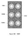
- FIG. 8 provide views of a three-dimensional electrode array embodiment comprising closely spaced apertures in plate electrodes.
- FIG. 9 provide views of a three-dimensional electrode array embodiment comprising different rod electrode materials.
- FIG. 10 provide views of a three-dimensional electrode array embodiment comprising different plate electrode materials.
- FIG. 11 provides a view of a three-dimensional electrode array in which a fluid surrounding the electrodes is induced to flow.
- FIG. 12 provides views of a three-dimensional electrode array comprising hollow tube rod electrodes.
- FIGS. 13A and 13B provide views of a three-dimensional electrode array comprising a first flowing fluid surround the plate electrodes and a second flowing fluid surrounding the rod electrodes.
- FIG. 14 provides views of a rod electrode embodiment.
- FIGS. 15A and 15B provide views of a three-dimensional electrode array comprising hollow tube rod electrodes.
- FIGS. 16A and 16B provide schematic drawings of a composite rod electrode structure.
- FIGS. 17A-17E provide schematic drawings of a three dimensional electrode array and optionally one or more flowing electrolyte components.
- FIGS. 18A and 18B provide views of a composite rod electrode structure comprising a porous rod.
- FIG. 19 provides experimental data of charge and discharge cycles of an electrochemical cell comprising a three-dimensional electrode array.
- FIG. 20 provides a view of a single aperture of a plate electrode showing multiple rod electrodes.
- FIG. 21 provides a schematic cross-sectional side view of a three-dimensional electrode array comprising branched rod electrodes.
- the inset shows a top view.
- FIG. 22 provides a schematic cross-sectional side view of a three-dimensional electrode array comprising a bridge type structure linking the rod electrodes.
- the inset shows a top view.
- Electrochemical cell refers to devices and/or device components that convert chemical energy into electrical energy or electrical energy into chemical energy. Electrochemical cells have two or more electrodes (e.g., positive and negative electrodes) and an electrolyte, wherein electrode reactions occurring at the electrode surfaces result in charge transfer processes. Electrochemical cells include, but are not limited to, primary batteries, secondary batteries and electrolysis systems. In certain embodiments, the term electrochemical cell includes fuel cells, superdapacitors, capacitors, flow batteries, metal-air batteries and semi-solid batteries. General cell and/or battery Construction is known in the art, see e.g., U.S. Pat. Nos. 6,489,055, 4,052,539, 6,306,540, Seel and Dahn J. Electrochem. Soc. 147(3) 892-898 (2000).
- Capacity is a characteristic of an electrochemical cell that refers to the total amount of electrical charge an electrochemical cell, such as a battery, is able to hold. Capacity is typically expressed in units of ampere-hours.
- specific capacity refers to the capacity output of an electrochemical cell, such as a battery, per unit weight. Specific capacity is typically expressed in units of ampere-hours kg ⁇ 1 .
- discharge rate refers to the current at which an electrochemical cell is discharged.
- Discharge current can be expressed in units of ampere-hours.
- discharge current can be normalized to the rated capacity of the electrochemical cell, and expressed as C/(X t), wherein C is the capacity of the electrochemical cell, X is a variable and t is a specified unit of time, as used herein, equal to 1 hour.
- “Current density” refers to the current flowing per unit electrode area.
- Electrode refers to an electrical conductor where ions and electrons are exchanged with electrolyte and an outer circuit.
- “Positive electrode” and “cathode” are used synonymously in the present description and refer to the electrode having the higher electrode potential in an electrochemical cell (i.e. higher than the negative electrode).
- “Negative electrode” and “anode” are used synonymously in the present description and refer to the electrode having the lower electrode potential in an electrochemical cell (i.e. lower than the positive electrode).
- Cathodic reduction refers to a gain of electron(s) of a chemical species
- anodic oxidation refers to the loss of electron(s) of a chemical species.
- Positive electrodes and negative electrodes of the present electrochemical cell may further comprises a conductive diluent, such as acetylene black, carbon black, powdered graphite, coke, carbon fiber, graphene, and metallic powder, and/or may further comprises a binder, such polymer binder.
- a conductive diluent such as acetylene black, carbon black, powdered graphite, coke, carbon fiber, graphene, and metallic powder
- binder such polymer binder.
- Useful binders for positive electrodes in some embodiments comprise a fluoropolymer such as polyvinylidene fluoride (PVDF).
- PVDF polyvinylidene fluoride
- Positive and negative electrodes of the present invention may be provided in a range of useful configurations and form factors as known in the art of electrochemistry and battery science, including thin electrode designs, such as thin film electrode configurations. Electrodes are manufactured as disclosed herein and as known in the art, including as disclosed in, for example
- the electrode is typically fabricated by depositing a slurry of the electrode material, an electrically conductive inert material, the binder, and a liquid carrier on the electrode current collector, and then evaporating the carrier to leave a coherent mass in electrical contact with the current collector.
- Electrode potential refers to a voltage, usually measured against a reference electrode, due to the presence within or in contact with the electrode of chemical species at different oxidation (valence) states.
- Electrode refers to an ionic conductor which can be in the solid state, the liquid state (most common) or more rarely a gas (e.g., plasma).
- Standard electrode potential (E°) refers to the electrode potential when concentrations of solutes are 1M, the gas pressures are 1 atm and the temperature is 25 degrees Celsius. As used herein standard electrode potentials are measured relative to a standard hydrogen electrode.
- Active material refers to the material in an electrode that takes part in electrochemical reactions which store and/or delivery energy in an electrochemical cell.
- “Cation” refers to a positively charged ion
- “anion” refers to a negatively charged ion
- Electrode contact and “electrical communication” refers to the arrangement of one or more objects such that an electric current efficiently flows from one object to another. For example, in some embodiments, two objects having an electrical resistance between them less than 100 ⁇ are considered in electrical communication with one another.
- An electrical contact can also refer to a component of a device or object used for establishing electrical communication with external devices or circuits, for example an electrical interconnection.
- Electrical communication also refers to the ability of two or more materials and/or structures that are capable of transferring charge between them, such as in the form of the transfer of electrons.
- components in electrical communication are in direct electrical communication wherein an electronic signal or charge carrier is directly transferred from one component to another.
- components in electrical communication are in indirect electrical communication wherein an electronic signal or charge carrier is indirectly transferred from one component to another via one or more intermediate structures, such as circuit elements, separating the components.
- Thermal contact and thermal communication are used synonymously and refer to an orientation or position of elements or materials, such as a current collector or heat transfer rod and a heat sink or a heat source, such that there is more efficient transfer of heat between the two elements than if they were thermally isolated or thermally insulated. Elements or materials may be considered in thermal communication or contact if heat is transported between them more quickly than if they were thermally isolated or thermally insulated. Two elements in thermal communication or contact may reach thermal equilibrium or thermal steady state and in some embodiments may be considered to be constantly at thermal equilibrium or thermal steady state with one another. In some embodiments, elements in thermal communication with one another are separated from each other by a thermally conductive material or intermediate thermally conductive material or device component. In some embodiments, elements in thermal communication with one another are separated by a distance of 1 ⁇ m or less. In some embodiments, elements in thermal communication with one another are provided in physical contact.
- FIG. 1A provides views of a plate electrode 101 of a three-dimensional electrode array embodiment, including side 101 A, top 101 B, front 101 C and perspective 101 D views.
- plate electrode 101 includes a plurality of apertures 102 , each having a circular shape.
- FIG. 1B provides views of a rod electrode 103 of a three-dimensional electrode array embodiment, including front 103 A, side 103 B and perspective 103 D views.
- rod electrode 103 has a circular cross-sectional shape.
- FIG. 2A provides a front view of a plate electrode.
- plate electrode includes a plurality of apertures of a variety of shapes.
- FIG. 2B provides a front view of a plurality of rod electrodes showing a variety of useful cross-sectional shapes.
- FIGS. 3A and 3B provide views of a three-dimensional electrode array 304 .
- FIG. 3A shows side 304 A and top 304 B views and
- FIG. 3B shows front 304 C and perspective 304 D views.
- Three dimensional electrode array 304 includes 6 plate electrodes 301 and 18 rod electrodes 303 .
- each rod electrode 303 passes through an aperture 302 of each of the 6 plate electrodes 301 .
- the vacant space between each of the plate electrodes, between each of the rod electrodes and between each of the plate electrodes and each of the rod electrodes (i.e., in the apertures) is filled with an electrolyte.
- FIGS. 4A and 4B provide views of a three-dimensional electrode array 404 .
- FIG. 4A shows side 404 A and top 404 B views and
- FIG. 4B shows front 404 C and perspective 404 D views.
- Three dimensional electrode array 404 includes 6 plate electrodes 401 and 18 rod electrodes 403 .
- each rod electrode 403 passes through an aperture 402 of each of the 6 plate electrodes 401 .
- Each plate electrode is flanked on both sides by a first electrolyte 405 .
- Each rode electrode is surrounded by a second electrolyte 406 .
- second electrolyte 406 and rod electrode 403 completely fill aperture 402 .
- first electrolyte 405 and second electrolyte 406 are different.
- views 404 A and 404 B show a cross sectional view of rod electrode 403 and surrounding second electrolyte 406 .
- FIGS. 5A and 5B provide views of a three-dimensional electrode array 504 .
- FIG. 5A shows side 504 A and top 504 B views and
- FIG. 5B shows front 504 C and perspective 504 D views.
- Three dimensional electrode array 504 includes 6 plate electrodes 501 and 18 rod electrodes 503 .
- each rod electrode 503 passes through an aperture 502 of each of the 6 plate electrodes 501 .
- each rod electrode includes a current collector 507 .
- one or more current collectors 507 are placed in thermal communication with a heat sink or heat source to control a temperature of the three-dimensional electrode array.
- FIG. 6 provides views of a three-dimensional electrode array 604 , showing side 604 A and perspective 604 B views.
- the space between plate electrodes 601 is smaller than the thickness of the plate electrodes 601 .
- FIG. 7A provides a side view of a three-dimensional electrode array 704 A, where the space between the plate electrodes 701 and the rod electrodes 703 is filled with a fluid 708 , such as a gas or a liquid electrolyte.
- FIG. 7B provides a side view of a three-dimensional electrode array 704 B, where the space between the plate electrodes 701 is filled with a solid 709 .
- FIG. 8 provides views of a three-dimensional electrode array 804 .
- FIG. 8 shows front 804 A, side 804 B and perspective 804 C views.
- the apertures 802 in the plate electrodes are closely space in this embodiment, for example at a distance less than 10% of the diameter of the apertures 802 .
- FIG. 9 provides views of a three-dimensional electrode array 904 and shows front 904 A and perspective 904 B views.
- the rod electrodes include two different materials, first rod electrode material 902 A and second rod electrode material 902 B.
- FIG. 10 provides views of a three-dimensional electrode array 1004 and shows side 1004 A and perspective 1004 B views.
- the plate electrodes include two different materials, first plate electrode material 1001 A and second plate electrode material 1001 B.
- Optional embodiments also include those with multiple plate electrode materials and multiple rod electrode materials.
- FIG. 11 provides views of a three-dimensional electrode array 1104 , including a side view 1104 A and a front view 1104 B.
- a thin tube 1110 fills each aperture in plate electrodes 1101 .
- the space between plate electrodes 1101 is filled with a first fluid 1108 A.
- electrolyte 1108 A is not shown in front view 1104 B.
- Each thin tube 1110 is filled with a second fluid 1108 B surrounding rod electrode 1103 .
- rod electrodes 1103 comprise an electron collector 1107 .
- a flow is provided such that fluid 1108 B flows in the direction shown by the arrows.
- FIG. 12 provides views of a three-dimensional electrode array 1204 and shows perspective 1204 A and side 1204 B views.
- rod electrodes 1203 are constructed as hollow tubes, such that fluid can flow along the interior of the rod electrodes 1203 as indicated by the arrows. Certain embodiments comprising hollow rod electrodes, are useful for a number of applications, including electrode array temperature control, fuel cell, metal-air batteries and flow batteries.
- rod electrodes 1203 comprise a porous material.
- FIGS. 13A and 13B provides views of a three-dimensional electrode array 1304 , including perspective 1304 A, front cross-sectional 1304 B and top 1304 C views.
- This embodiment comprises 3 plate electrodes 1301 and 6 rod electrodes 1303 .
- the space between the plate electrodes 1301 is filled with a first fluid 1308 A.
- perspective view 1304 A does not show first fluid 1308 A.
- Surrounding each rod electrode 1303 is a thin tube 1310 filled with a second fluid 1308 B.
- Each thin tube 1310 fills an entire aperture in plate electrodes 1301 .
- thin tubes 1310 are indicated by a dashed line.
- first fluid 1308 A is induced to flow within thin tubes 1310 , for example, as shown by the arrows in front cross-sectional view 1304 B.
- second fluid 1308 B is induced to flow across the space between plate electrodes 1301 , for example, as shown by the arrows in FIG. 13B .
- First fluid 1308 A flows in the spaces between plate electrodes 1301 and second fluid 1308 B flows within thin tubes 1310 .
- the plate electrodes 1301 comprise graphite and are optionally useful as an anode.
- the rod electrodes 1303 comprise a carbon shell and include electron collectors (not shown) comprising copper.
- first fluid 1308 A and second fluid 1308 independently comprises electrolytes.
- first fluid 1308 A comprises a first electrolyte and a first active material
- second fluid 1308 B comprises a second electrolyte and a second active material.
- first fluid 1308 A comprises a first electrolyte
- second fluid 1308 B comprises a second electrolyte.
- first fluid 1308 A comprises a fuel, such as H 2
- second fluid 1308 B comprises an oxygen containing fluid, such as air.
- FIG. 14 provides views of a rod electrode embodiment 1403 , including end view 1404 A and cross-sectional view 1404 B.
- each rod electrode 1403 comprises an electrode pair, including rod inner core 1403 A and rod outer shell 1403 B.
- rod inner core 1403 A comprises a first electron collector 1407 A.
- rod outer shell 1403 B comprises a second electron collector 1407 B.
- material 1408 Between rod inner core 1403 A and rod outer core 1403 B is material 1408 .
- each rod electrode 1403 is an electrochemical cell, and material 1408 comprises an electrolyte.
- Rod electrodes of the embodiment shown in FIG. 14 are useful, for example, in any three-dimensional electrode array described herein.
- the rod electrode inner core and a plate electrode comprise identical or substantially identical materials.
- Embodiments of this aspect are useful, for example, for increasing the ratio of the amount of the rod inner core/plate material to the amount of rod outer core material.
- FIGS. 15A and 15B provide three-dimensional views of a three-dimensional electrode array 1504 .
- many plate electrodes are stacked, sandwiching materials, such as a solid electrolyte, between the plate electrodes.
- Many rod electrodes are shown, including a current collector.
- the current collectors are held under tension to provide structural rigidity to the electrode array.
- FIGS. 16A and 16B provide views of a composite rod electrode structure.
- FIG. 16A provides an end view of the composite rod electrode structure 1600 having electrodes 1601 , electrode 1602 , current collector 1603 and electrolyte 1604 .
- FIG. 16B provides a cross sectional side view of the composite rod electrode 1600 also showing electrodes 1601 , electrode 1602 , current collector 1603 and electrolyte 1604 .
- electrodes 1601 are an anode and electrode 1602 is a cathode.
- the invention includes composite rod electrodes wherein electrodes 1601 is a cathode and electrode 1602 is an anode.
- composite rod electrode structure 1600 provides an electrochemical cell, a fuel cell, a flow cell, a metal air battery, or a supercapacitor device.
- FIGS. 17A-17E provide schematic drawings of three-dimensional electrode arrays, optionally including one or more flowing electrolyte components.
- FIG. 17A provides a side view of an electrode array electrode structure 1700 A having plate electrodes 1701 A, rod electrodes 1702 A, first electrolyte 1703 A, second electrolyte 1704 A and membrane 1705 A.
- rod electrodes 1702 A extend through holes provided in plate electrodes 1701 A.
- Rod electrodes 1702 A are provide in an array geometry and plate electrodes 1701 A are provided in a stacked configuration.
- plate electrodes 1701 A and rod electrodes 1702 A are solid electrodes.
- first electrolyte 1703 A and second electrolyte 1704 A are independently a solid, a gel or a fluid electrolyte. In an embodiment, for example, first electrolyte 1703 A and second electrolyte 1704 A are the same electrolyte. In an alternative embodiment, for example, first electrolyte 1703 A and second electrolyte 1704 A are different electrolytes.
- membrane 1705 A is a solid membrane providing a barrier between plate electrodes 1701 A and rod electrodes 1702 A.
- FIG. 17B provides a side view of an electrode array structure 1700 B having plate electrodes 1701 B, rod electrodes 1702 B and membrane 1705 B and demonstrating an embodiment including a flowing electrolyte configuration, for example, having a flowing first electrolyte 1703 B and a flowing second electrolyte 1704 B.
- the arrows indicate the direction of flow of electrolytes.
- electrolyte 1703 B is a flowing fluid that optionally includes active nanoparticles and/or microparticles, for example, which participate in oxidation—reduction reactions.
- electrolyte 1704 B is a flowing fluid that optionally includes active nanoparticles and/or microparticles, for example, nanoparticles and/or microparticles which participate in oxidation—reduction reactions.
- FIG. 17C provides a side view of an electrode array structure 1700 C, for example for an electrochemical cell, having plate electrodes 1701 C, rod electrodes 1702 C, first electrolyte 1703 C, second electrolyte 1704 C, membrane 1705 C and space 1706 C.
- space 1706 C is filled with liquid to control the temperature of the cell or to remove the unwanted products from the cell, for example, via membrane 1705 C.
- space 1706 C is filled with electrolyte or with porous PE or porous PP and electrolyte.
- FIGS. 17D and 17E provide a side view of the composite rod electrode structure 1700 C used in a flowing electrolyte configuration, for example, having a flowing first electrolyte 1703 C and a flowing second electrolyte 1704 C.
- the arrows indicate the direction of flow of electrolyte.
- the system may have a flowing first electrolyte 1703 C and a flowing second electrolyte 1704 C.
- the system may have a flowing first electrolyte 1703 C, a flowing second electrolyte 1704 C and a flowing electrolyte in space 1706 C.
- a barrier 1707 C is optionally provided, for example comprising a thin tube of inert material.
- FIGS. 18A and 18B provide views of a composite rod electrode comprising a porous rod.
- FIG. 18A provides an end view of the composite rod electrode structure 1800 having an anode or cathode 1801 , current collector 1803 , an electrolyte 1804 , and pores 1805 .
- FIG. 18B provides a cross sectional view of the composite rod electrode 1800 also having an anode or cathode 1801 , current collector 1803 , an electrolyte 1804 , and pores 1805 .
- electrolyte 1804 comprises a fluid.
- electrolyte 1804 comprises a solid.
- electrolyte 1804 comprises a fluid and a separator.
- pores 1805 provide for fluid communication of the electrolyte 1804 inside the composite rod electrode structure 1800 to components outside of the rod electrode structure 1800 , for example plate electrodes and the space between the plate electrodes.
- FIG. 19 provides data showing a charge-discharge curve for cycling an electrochemical cell embodiment comprising a three-dimensional electrode array including Ewe versus time and Current (I) versus time.
- the cell comprises two parallel plates comprised of LiMn 2 O 4 , each of dimensions 10 mm ⁇ 10 mm ⁇ 0.2 mm with an Al current collector of 0.01 mm thick in the middle of the LiMn 2 O 4 plate electrode.
- the cell also comprises four graphite rod electrodes of 2.5 mm diameter with a 0.1 mm diameter copper electron collector core.
- the voltage, Ewe, shown in FIG. 18 is with respect to the standard hydrogen electrode (SHE).
- FIG. 20 provides a view of a single aperture of a plate electrode showing multiple rod electrodes 2001 positioned within the single plate electrode.
- rod electrodes include an electron collector 2003 and the aperture is filled with a fluid 2004 .
- fluid 2004 is an electrolyte.
- fluid 2004 is a flowing fluid that optionally includes active nanoparticles and/or microparticles, for example, nanoparticles and/or microparticles which participate in oxidation-reduction reactions.
- FIG. 21 provides a schematic cross-sectional side view of a three-dimensional electrode array comprising branched rod electrodes.
- the inset shows a top view.
- the electrode array comprises plate electrodes 2101 , rod electrodes 2102 and electrolyte 2103 .
- a space is provided between plate electrodes 2101 and is optionally filled with a solid, fluid or gel electrolyte 2104 .
- the inset view does not show electrolyte 2104 .
- Rod electrodes 2102 branch along lateral dimensions from an aperture in plate electrodes 2101 .
- electrolyte 2103 which separates rod electrodes 2102 from plate electrodes 2101 , is applied as a coating on the rod electrode 2102 .
- FIG. 22 provides a schematic cross-sectional side view of a three-dimensional electrode array comprising a bridge type structure linking the rod electrodes.
- the inset shows a top view.
- the electrode array comprises plate electrodes 2201 , rod electrodes 2202 and electrolyte 2203 .
- a space (not explicitly shown in the cross-sectional view) is provided between plate electrodes 2201 and is optionally filled with a solid, fluid or gel electrolyte 2204 .
- the inset view shows electrolyte 2204 surrounding rod electrode 2202 and electrolyte 2203 .
- Rod electrodes 2202 form bridges to neighboring rod electrodes 2203 along lateral dimensions from an aperture in plate electrodes 2101 .
- electrolyte 2203 which separates rod electrodes 2202 from plate electrodes 2201 , is applied as a coating on the rod electrode 2202 .
- some of the holes are optionally used only for structural integrity, by using metal or ceramic or glass or polymer rods, for example, steel rods. These holes optionally have larger diameter than the electrode rod holes.
- Some of the space bottom the parallel plates are optionally also used only for structural integrity, by using metal or ceramic plates. For example by using steel plates or glass plates.
- An advantage of the designs described herein is that the maintenance can be done easier and faster, for example, when the cell is composed of many individual rods and plates. Another advantage is that, as the ratios of volume/foot-print surface area and active surface area/foot print surface area can be increase significantly over prior art designs, there is much less of the problem of electrolyte evaporation (which is a major problem, for example, in metal air batteries and in fuel cells) or ambient air-moisture contamination.
- current collectors are included in a three-dimensional cell. Not only are current collectors useful for transporting electrons in charge-discharge, but also current collectors optionally provide mechanical-structural stability to the cell. Optionally, some current collectors are used to help with the temperature control of the cell and thus can hinder overheating of the battery and can increase the performance and life.
- the current collector/temperature control element is solid or is liquid such as a molten metal or molten salt flowing inside a tube-pipe or it can be a metallic tube, for example Al or Cu or Ni to transport electrons, where inside the tube there is a fluid such as air or a liquid coolant such as oil or water or heat transfer fluid that can flow from one end to the other end, and be useful for controlling the temperature of the cell, for example for mid-large scale applications such as electric cars, renewable energy storage and grid storage.
- a separator is optionally included between the rods and the walls of the plates to avoid their contact.
- useful materials include PE or PP or a combination from Celgard co.
- the thickness is, for example, between 0.010 mm to 0.5 mm, or about 0.02 mm.
- an electrolyte comprises an imide salt.
- the distance between the parallel plates is optionally filled with a material solely for temperature control such as heat pipe or heat pin that can use thermal conductivity and phase transition.
- a material solely for temperature control such as heat pipe or heat pin that can use thermal conductivity and phase transition. This is especially useful in mid-large scales, such as in electric cars and grid storage.
- a material is a screen made of metals, such as thin steel or copper (e.g., a few micrometers thick for small cells to a few centimeters thick for bigger cells). There is no contact between the screen and the rods.
- the space between plates is optionally filled with oil or water or a heat transfer fluid to maintain the temperature of the cell at a specified temperature by using a thermostat.
- This liquid is optionally separated from the electrolyte between the rods and the hole-walls by using inert material (as an example PTFE or Silicone) gaskets with the shape of a long cylinder (as long as the rods) with outer diameter equals that of the holes, and thickness of, as an example about 1 mm, which is completely solid between the plates and is more than 80% open at the vicinity of the walls of the holes.
- inert material as an example PTFE or Silicone
- two diaphragms, donut shape: each 0.05 wide and 0.05 thick, are optionally placed at the top and bottom of the holes to completely prevent the mixture of the cooling liquid with the electrolyte.
- a gas or liquid coolant is used for controlling an electrode array temperature.
- Useful gas coolants include air, hydrogen, inert gases such as nitrogen, helium or carbon dioxide or Sulfur hexafluoride or steam.
- Useful liquid coolants include oil, mineral oil, castor oil, water, deionized water, heavy water, liquefied neon, molten salts, NaF—NaBF 4 , FLiBe, FLiNaK, liquid lead, liquid lead-bismuth alloy, silicone oils, fluorocarbon oils, Freons, Halomethanes, ammonia, sulfur dioxide, carbon dioxide, Polyalkylene glycol, or can be a solution of an organic chemical in water, such as betaine, ethylene glycol, diethylene glycol, propylene glycol.
- Useful coolants further include liquids such as liquid nitrogen, liquid helium, liquid hydrogen.
- the coolant is optionally a solid such as dry ice or water ice.
- Useful coolants also include nanofluids or semisolids comsisting of a carrier liquid such as water dispersed with tiny (10 nm to a few mm size) particles made of CuO, Aluminia, titanium dioxide, carbon nanotubes, carbon powders, silica, or metals such as copper or silver.
- each of the electrodes or electrolytes or dielectric materials are a heterogeneous material such as a layered composite, such as a first material with a second coating at least on one side of it.
- the electrochemical energy storage apparatus has at least a positive terminal and a negative terminal which are electrically insulated from each other. It also has a non-electro-conductive material, which can be solid or fluid or gas, between the two terminals. This medium is a conductor for some of the ions of materials used for the terminals. Electro conductive materials such as metals can be used on the outer surface of the terminals to facilitate the passage of the electrons. Related methods of constructing and controlling an electro chemical energy storage system are also disclosed. An electro chemical energy power system utilizing an electrochemical energy storage apparatus is further disclosed, as is a charge exchanger for the electrochemical energy storage system.
- the medium between the terminals can be selected from the group consisting of a salt, a salt mixture, a eutectic salt mixture, lithium nitrate, potassium nitrate, sodium nitrate, sodium nitrite, calcium nitrate, lithium carbonate, potassium carbonate, sodium carbonate, rubidium carbonate, magnesium carbonate, lithium hydroxide, lithium fluoride, beryllium fluoride, potassium fluoride, sodium fluoride, calcium sulfate, barium sulfate, lithium sulfate, lithium chloride, potassium chloride, sodium chloride, iron chloride, tin chloride, and zinc chloride, sulphuric acid, water and any combination of these.
- the terminals can have any shape and geometry, such as plates or tubes or cylinders or parts of them.
- the whole storage system is contained in a non-conductive container.
- non-conductive spacers can be used between the terminals especially when the medium is a fluid or gas to prevent short circuit through physical contact.
- the container comprise a conductive material or a non-conductive material such as a material selected from the group consisting of plastics, ceramics, firebrick, refractory material, castable refractories, refractory brick, mixtures of alumina (Al 2 O 3 ), silica (SiO 2 ), magnesia (MgO), zirconia (ZrO 2 ), chromium oxide (Cr 2 O 3 ), iron oxide (Fe 2 O 3 ), calcium oxide (CaO), silicon carbide (SiC), carbon (C); metallic materials, plain carbon steels; alloy steels, manganese, silicon, silicon-manganese, nickel, nickel chromium, molybdenum, nickel-molybdenum, chromium, chromium-molybdenum, chromium molybdenum-cobalt, silicon-molybdenum, manganese-silicon-molybdenum, nickel-chromium molybdenum-co
- the base for the storage system comprises a material selected from the group consisting of earth, firebrick, refractory material, concrete, castable refractories, refractory concrete, refractory cement, insulating refractories, gunning mixes, ramming mixes, refractory plastics, refractory brick, mixtures of alumina (Al 2 O 3 ), silica (SiO 2 ), magnesia (MgO), zirconia (ZrO 2 ), chromium oxide (Cr 2 O 3 ), iron oxide (Fe 2 O 3 ), calcium oxide (CaO), silicon carbide (SiC), carbon (C); metallic materials, carbon steels; alloy steels, manganese, silicon, silicon-manganese, nickel, nickel-chromium, molybdenum, nickel-molybdenum, chromium, chromium-molybdenum, chromium-molybdenum-cobalt, silicon-molybden
- an energy storage system can be positioned such that the terminals face vertical, such that the terminals face the ground, such that the terminals face horizontal, such that the terminals do not face the ground, for example, perpendicular to the ground.
- a group of terminals can be used in parallel or series configurations.
- the terminals comprise material selected from the group consisting of iron oxides; metals; lithium phosphates; sodium phosphates; plain carbon steels; graphite, lead metal, lead dioxide, alloy steels, manganese, silicon, silicon-manganese, nickel, nickel-chromium, molybdenum, nickel-molybdenum, chromium, chromium-molybdenum, chromium-molybdenum-cobalt, silicon-molybdenum, manganese-silicon-molybdenum, nickel-chromium-molybdenum, silicon-chromium-molybdenum, manganese-chromium-molybdenum, manganese-silicon-chromium molybdenum, vanadium, chromium-vanadium, silicon-chromium-vanadium, manganese-silicon chromium-vanadium, chromium-vanadium-molybdenum, manganese-silicon-silicon
- the system used for a 400 MWh storage can be made of a plates of 35 m by 35 m with the thickness of a few centimeters as the terminals and medium of a few centimeters thickness between them.
- the plates can be parallel to each other and they can be either standing vertically in or above the ground or they can be parallel to the ground in or above the ground.
- the materials used as an example can be an oxide such as lithium ion phosphate, and graphite as the plates with a medium of lithium salts, such as LiPF 6 , LiBF 4 , or LiClO 4 , in an organic solvent, such as ether.
- a medium of lithium salts such as LiPF 6 , LiBF 4 , or LiClO 4
- organic solvent such as ether
- Another example can be the same geometry as above but with the materials of lead metal (Pb) and lead (IV) dioxide (PbO 2 ) in a medium of about 33.5% v/v (6 Molar) sulphuric acid (H 2 SO 4 ).
- the electricity source from the energy source is connected to the two terminals.
- the electric energy makes one of the terminals to get reduced and the other one to get oxidized. This way the ions from one terminal leave the terminal and go the medium.
- the medium transfers the ions to the opposite terminal. This way the chemical energy is stored in the system. Then the electricity source is opened from the storage system.
- the two plates are connected to each other by a conductive material, with the user application between the two ends of the conductive material.
- the chemistry used in the system can be any known chemistry of batteries such as Lead-Acid battery, NaS battery, Metal-Air battery, Li-ion battery, etc., however the electrode geometry is different. Optionally, it is in larger scales and it can be honey-comb geometry or any other porous geometry. Thin honey comb structures are optionally used, to minimum stresses due to shape changes in charge/discharge. Optionally, a sponge type matrix filled with the electrode material can be utilized.
- the thickness of the plates or the diameter of the cables/rods/wires can optionally be millimeters or centimeters.
- the width and length of the plates and the length of the cables/rods/wires can optionally be centimeters or meters.
- the plates and cables/rods/wires can be connected in any combination of parallel or series.
- the system can be buried under the ground or can be put in a room to stay away from the environmental hazards including temperature changes. All the solid parts can be controlled at the boundaries such as by pulling the cables/rods/wires to minimize the risk of electrical shorts in the system.
- the new configuration described here can be used for primary and secondary batteries. It can transform primary batteries to secondary batteries and it can provide better cyclability and safety for secondary batteries.
- the new configuration can be used for primary and secondary lithium batteries.
- Lithium metal anode in Lithium based batteries has energy density an order of magnitude higher than currently used carbon anode. Though, due to the formation of dendrites on lithium anode during the recharging process, the cell may short circuit and explode. For this reason in rechargeable batteries, currently, carbon anode is the only option. In addition to lower energy density comparing to lithium metal, carbon anodes needs special electrolytes, which adds to the cost.
- the new configuration described herein solves the shorting problem in Li-metal anodes. This will result in much cheaper rechargeable batteries that can last longer than available lithium based batteries.
- the active electrochemical materials compose only one third of the weight of a battery pack.
- the problem is that the prior art battery configurations limit the size of the battery.
- one goal of the present systems is to remove the constraints on the size of the battery pack by changing the configuration. This makes the batteries more efficient, as there is less need of the supporting materials that do not play any electrochemical roles. It results in getting closer to ideal battery systems for electric vehicles. In addition, it results in lighter and cheaper batteries that can be used for large-scale energy storage systems needed for grid electricity storage and also renewable energy sources such as solar farms and wind farms.
- the new configuration/geometry described herein can improve all battery chemistries including those with the Li-metal anode.
- perforated anode (or cathode) plates are placed parallel to each other with electrolyte between them.
- Cathode (or anode) rods go through the plate holes to form a mesh.
- the radius of each rod is less than that of the holes to allow for the electrolyte passage between the rods and the holes.
- the wall of the holes can be covered with an inert material so that dendrites do not happen between the opposite electrodes but happen between the lithium plates.
- Each plate can have different geometries such as rectangular plates, cylindrical plates or any other geometry.
- the thickness of each of the plates can be from 20 nm to 5 cm, as an example around 100 micrometers for lithium batteries and 2 mm for lead-acid batteries.
- the holes of the plates can have different geometries such as cylindrical or rectangular or any other geometry.
- the radius of the holes can be from 10 nm to 2 cm, as an example 50 micrometers for lithium batteries and 500 micrometers for lead-acid batteries.
- the rods can have different geometries similar to the holes with the radius smaller than the holes.
- the surface fraction of the holes is arbitrary.
- the distance between the holes can be a few nanometers to a few millimeters, as an example can be a few micrometers in lithium batteries and a few hundred micrometers in lead acid batteries.
- the plates can be from 20 nm to 20 meters long/wide, as an example 10 mm for lithium batteries and 10 cm for lead-acid batteries.
- the distance between any two plates can be from 10 nm to 5 cm, as an example 10 micrometers, as an example 1 micrometer for lithium batteries and 1 mm for lead acid batteries.
- the inert material covers the walls of the holes. It can be made of any material that doesn't have any chemical or electrical reaction with the electrodes or electrolyte, such as rubber, plastic, or ceramics. Its thickness can be from a few nanometers to a few millimeters.
- Li-metal anode As an example a Li-metal anode is considered. Lithium metal used as an anode active material has a very high theoretical capacity of 3860 Ah/kg, which is the highest among metallic anode materials. In addition, the standard electrode potential of lithium is high ( ⁇ 3.045V vs SHE). This makes lithium metal a very attractive anode material.
- Li-metal anodes are only used in primary lithium batteries. They can't be used in rechargeable cells due to the lithium dendrites that form on the lithium metal anode in the recharging process. The dendrites make shorts between the opposite electrodes and cause fire and explosion of the cell.
- the high energy density of lithium metals cells is still very attractive, if the safety problem can be overcome.
- the conductivity of the nonaqueous electrolyte used in the AA-size lithium metal anode prototype cells is one order of magnitude lower than that of an aqueous system. Thus, if one can solve the safety problem, the rate of charging of the battery will improve a lot.
- the new configuration/geometry described herein improves all battery chemistries including those with the Li-metal anode.
- perforated anode plates are placed parallel to each other with electrolyte between them.
- the cathode rods go through the plate holes to form a mesh.
- the radius of each rod is less than that of the holes to allow for the electrolyte passage between the rods and the holes.
- the wall of the holes can be covered with an inert material so that dendrites do not happen between the opposite electrodes but happen between the lithium plates.
- Each plate can have different geometries such as rectangular plates, cylindrical plates or any other geometry.
- each of the plates can be from 20 nm to 5 cm, as an example around 100 micrometers.
- the holes of the plates can have different geometries such as cylindrical or rectangular or any other geometry.
- the radius of the holes can be from 10 nm to 2 cm, as an example 50 micrometers.
- the rods can have different geometries similar to the holes with the radius smaller than the holes.
- the plates can be from 20 nm to 20 meters long/wide.
- the distance between any two plates can be from 10 nm to 5 cm, as an example 10 micrometers.
- cathode There are many possible choices for the cathode. The most popular are lithium manganese dioxide, lithium cobalt, and FeS 2 . The suggested configuration/geometry works for any chemistry of batteries including the lithium-air chemistry.
- the temperature of the cell also plays an important role on the safety and cyclability of the battery.
- a novel approach is suggested here. If current collectors are needed the cathode current collector is in the core of the rods; the anode current collector, if needed, can be formed of a grid in the plate. As each current collector runs in the entire cell, by using the current collectors as heat conductive material we can set the cell temperature very cheap and effectively.
- the lead acid cell can be demonstrated using sheet lead plates for the two electrodes.
- the plate dimensions are typically about 50 ⁇ 50 ⁇ 1.5 mm. Since the capacity of a lead-acid battery is proportional to the surface area of the electrodes that is exposed to the electrolyte, various schemes are employed to increase the surface area of the electrodes per unit volume or weight. Plates are grooved or perforated to increase their surface area. Faure pasted-plate construction is typical of automotive batteries.
- Each plate consists of a rectangular lead grid alloyed with antimony or calcium to improve the mechanical characteristics.
- Each plate consists of a rectangular lead grid alloyed with antimony or calcium to improve the mechanical characteristics.
- the holes of the grid are filled with a paste of red lead and 33% dilute sulfuric acid. (Different manufacturers vary the mixture).
- the paste is pressed into the holes in the grid which are slightly tapered on both sides to better retain the paste. This porous paste allows the acid to react with the lead inside the plate, increasing the surface area many fold.
- the positive and negative plates are similar; however expanders and additives vary their internal chemistry to assist in operation.
- the present design results in higher energy densities and also less problems with the volume changes of the electrodes.
- the present design results in more cyclability due to more homogeneous cell design and by putting the positive electrodes parallel to each other and the ground, the active material just transfers from the top layers to the bottom layers but will not be lost. This also adds to the safety of the cell by reducing the likelihood of shorts.
- Positive electrode 20 plates of 400 ⁇ 400 ⁇ 5 mm as the grid with holes of 5.5 mm diameter with a distance between the holes of 5 mm, wall to wall
- Negative electrodes rods with diameter of 5 mm.
- the rods can be placed horizontally; optionally a metal such as steel core is used to support the rods mechanically.
- This example describes the use of a LiMn 2 O 4 cathode (0.2 mm thick two sided with an aluminum current collector 15 micrometers in between) and a graphite anode (0.2 mm thick two sided with the copper current collector 15 micrometers in between) with 1-molar LiClO 4 —PC electrolyte in the new design as follows.
- This sample electrochemical cell is in the form of a cube with 1 cm 3 volume.
- Materials 40 perforated plates, each 10 mm ⁇ 10 mm with an array of 10 ⁇ 10 holes evenly distributed, of LiMn 2 O 4 cathode.
- the rods also have a 0.05 mm thick, outer shell, separator, for example PP or PE from Celgard, around them.
- the holes in the plates are each 0.95 mm diameter.
- the distance between the holes, wall to wall, is then 0.05 mm.
- the active surface area of the LiMn 2 O 4 cathode here then includes: 2350 mm 2 on the surface between the holes (40 two sided perforated plates) AND 2390 mm 2 on the walls of the holes. This shows that the new design has 4740 mm 2 surface area which is about 2 times more surface area comparing to the conventional to parallel plate design with the same amount of cathode material.
- the active surface area of the graphite anode is 2665 mm 2 which is still slightly higher than the conventional design.
- the space between the parallel plates is filled by perforated plates, at least on the very top and very bottom layer.
- this is made of desiccants such as silica gel, activated charcoal, calcium sulfate, calcium chloride, montmorillonite clay, and molecular sieves materials.
- the material can be covered in a very thin inert coating such as 0.01 mm PTFE. This helps to increase the safety, performance and life of Li batteries, especially in Li-air batteries.
- the desiccant layers can be removed and replaced after they are saturated with water.
- Useful battery chemistries for this design include: alkaline battery, Zn—MnO2 primary, Zn—MnO 2 secondary, Zn-Air, Zn—AgO, Ni—Zn, Cd—AgO, Zn—HgO, Cd—HgO Ni—Cd, Ni-Metal Hydride, or Ni—H 2 battery.
- a thin membrane is useful. For example about tens of micrometers thick, between the two electrolyte systems to separate them, for example when they are both fluid such as liquid, as an example similar to a thin O-ring.
- the membrane is used to remove unwanted products from the cell or to add assisting materials to the cell. Examples of removing unwanted products from the cell include some gas phases that happen as the product of the chemistry cell reactions, such as hydrogen gas as for example it happens in Flow batteries or in Lead Acid batteries, especially in flooded lead-acid batteries.
- the membranes used here optionally are inert materials such as PTFE or PE or other membrane products with desired pore sizes or chemistry or surface behavior.
- Each rod is: a (Ni-mesh carbon-layers) tube comprising a manganese-based catalyzed carbon layer on a screen of Ni.
- Electrolyte is KOH, for example, 5M in water.
- the anode is a zinc metal, for example with a rough surface such as from applying sand paper on it, as the perforated plates.
- the air cathode contains a hydrophobic Teflon layer (inner part of the tube, for example porous to allow oxygen but stop vapor), a thin Nickel mesh layer acting as a current collector and providing a structural support (middle layer of the tube), and a carbon catalyst layer (outer part of the tube).
- the manganese-based catalyzed carbon layer is, for example 0.5 mm thick.
- the tube inner radius is, for example, 1 mm.
- the separator can be, for example, PVA.
- the thickness of the Zn plates is, for example, 2 mm.
- the dimensions of the cell are, for example, 1 cm diameter cylinder with the height of 1 cm.
- the distance between the Zn plates is optionally partially filled with electrolyte, here with KOH solution in water and partially with 0.2 mm perforated steel plates, and partially filled with air.
- electrolyte here with KOH solution in water and partially with 0.2 mm perforated steel plates
- air partially filled with air.
- a space partially filled with liquid electrolyte and air helps with the life of the battery.
- Zero space is used between Zn plates and have 5 parallel Zn plates, each 2 mm, to resemble one Zn plate of 1 cm thick.
- the entire cell is inside a case made of steel and covered by a skin made of PTFE.
- the case has openings on two parallel sides, say top and bottom, to allow the air flow.
- a benefit of the new design is that the tubes are open from both ends so the cell can get more air.
- EXAMPLE 8 Zn-Air Battery with Assisted Flow
- Each rod is: a (Ni-mesh carbon-layers) tube comprising a manganese-based catalyzed carbon layer on a screen of Ni.
- the electrolyte is KOH.
- the anode is a zinc metal, for example, with a rough surface, such as from applying sand paper on it, as the perforated plates.
- the air cathode contains a hydrophobic Teflon layer (inner part of the tube, for example, porous to allow oxygen but stop vapor), a thin Nickel mesh layer acting as a current collector and providing a structural support (middle layer of the tube), and a carbon catalyst layer (outer part of the tube).
- holes in the plates of metal electrode for example Zn perforated plates, have the same size for each plate but have a different size for different plates.
- the manganese-based catalyzed carbon layer is 0.5 mm thick.
- the tube inner radius is variable, for example linearly varying from 0.5 mm from one side to 2 mm on the other side.
- the size of the holes-inner radius can be optimized, using fluid mechanics principles based on the density and temperature and viscosity and other parameters of the flow, for efficient flow of the cathode electrode, here air, through them. Further assisted flow can be applied by using pumps, for example, at the two ends of the cell where there is access to air to facilitate the flow of the cathode materials, here air.
- the separator can be for example PVA.
- the thickness of the Zn plates is, for example, 2 mm.
- the dimensions of the cell are, for example, 1 cm diameter cylinder with the height of 1 cm.
- the distance between the Zn plates is optionally partially filled with electrolyte, here with KOH solution in water and partially with 0.2 mm perforated steel plates, and partially filled with air.
- electrolyte here with KOH solution in water and partially with 0.2 mm perforated steel plates
- air partially filled with air.
- a space partially filled with liquid electrolyte and air helps with the life of the battery.
- Zero space is used between Zn plates and have 5 parallel Zn plates, each 2 mm, to resemble one Zn plate of 1 cm thick.
- the entire cell is inside a case made of steel and covered by a skin made of PTFE.
- the case has openings on two parallel sides, for example, top and bottom, to allow the air flow.
- the setup of the cells comprises metallic lithium as the anode, three membrane laminates (two PC layers and one LAGP layer), and a cathode.
- the membrane is PC(BN)/LAGP/PC(BN) with the thickness of 1.5 mm, where each layer of pC is about 200-300 micrometers thick.
- the plates are 20 mm ⁇ 20 mm ⁇ 0.4 mm.
- the cathode is 25% C*+75% LAGP on Ni mesh tube.
- the cathode tube has an inner opening of 1 mm diameter. Its thickness is 0.5 mm.
- C* is 60% PWA activated carbon+40% Ketjen carbon black.
- the air cathode contains a hydrophobic Teflon layer, on the inner size, say 0.01 thick (inner part of the tube is, for example, porous to allow oxygen but stop vapor), a thin Nickel mesh layer acting as a current collector and providing a structural support (middle layer of the tube), and a carbon catalyst layer (outer part of the tube).
- a hydrophobic Teflon layer on the inner size, say 0.01 thick (inner part of the tube is, for example, porous to allow oxygen but stop vapor), a thin Nickel mesh layer acting as a current collector and providing a structural support (middle layer of the tube), and a carbon catalyst layer (outer part of the tube).
- the cell comprises 4 parallel Li perforated plates.
- the distance between the plates is optionally partially filled with liquid nonaquous electrolyte, for example, 1M LiPFe/PC/EC/DMC (1:1:3) and partially with 0.2 mm perforated steel plates, and partially can be filled with dry oxygen.
- zero space is used between plates and there are 5 parallel plates, each 0.4 mm, to resemble one plate of 1 mm thick.
- the entire cell can is inside a case made of steel and covered by a skin made of PTFE.
- the case has openings on two parallel sides, top and bottom, to allow the air flow.
- Useful electrodes for flow batteries include, but are not limited to: Vanadium, Bromine, Iron, H 2 -Zinc, Cerium, B 2 , Chromium, Polysulfide and any combination of these.
- electrolytes Two electrolytes are used, one surrounding the anode and one surrounding the cathode.
- Useful electrolytes include, but are not limited to, H 2 SO 4 , VCl 3 —HCl, NaBr—HCl, NaS 2 , NaBr, HCL, Polymer Electrolyte Membrane-HBR, ZnBr 2 , CH 3 SO 3 H and any combination of these.
- a redox flow battery with a stack of perforated cells and a group of rods (arbitrary aspect ratio; from one that is a circle cross section to a very large number that is a rectangular cross section; the cross-section itself can vary for example in size), with anolyte and catholyte compartments divided from each other by an ionically selective and conductive separator and having respective electrodes.
- the battery has anolyte and catholyte tanks, with respective pumps and a pipework. In use, the pumps circulate the electrolytes to and from the tanks, to the compartments and back to the tanks. Electricity flows to a load.
- the electrolyte lines are provided with tappings via which fresh electrolyte can be added and further tappings via which spent electrolyte can be withdrawn, the respective tappings being for anolyte and catholyte.
- a remote pump pumps fresh anolyte and fresh catholyte from remote storages and draws spent electrolyte to other remote storages.
- the cell comprises: an anode in a catholyte compartment, a cathode in an anolyte compartment and, an ion selective membrane separator between the compartments, a pair of electrolyte reservoirs, one for anolyte and the other for catholyte, and electrolyte supply means for circulating anolyte from its reservoir, to the anolyte compartment in the cell and back to its reservoir and like circulating means for catholyte;
- the battery comprising: connections to its electrolyte reservoirs and/or its electrolyte supply means so that the battery can be recharged by withdrawing spent electrolyte and replacing it with fresh electrolyte,
- the electrolyte divider or membrane is optionally a diaphragm between each rod and the walls of the corresponding holes. It optionally is a thin tube shape that the inner and outer radii are chosen to fit between the rod and the corresponding wall and is as long as each of the rods or it can be a thin tube shape as long as the thickness of each of the perforated plates.
- Electrolyte 1 and 2 are the same in this example: between rods and walls of the holes and between the plates: 2M VOSO 4 in 2M H 2 SO 4 . Temperature: 25 Celsius.
- Negative Electrode Graphite rods, 100 mm long, 1 mm thick on a copper wire of 1 mm diameter. The wires are held in tension from the top and bottom outside of the cell, so that they stay straight. Electrolyte) runs from the outside of the cell into the cell from one end, from the holes between the rods and the walls of the holes in plates; and exits from the opposite end. A pumping system is optionally used to flow the electrolyte 1.
- Electrode 10 Platinized titanium Perforated Plates which are 100 ⁇ 100 ⁇ 3-mm. The holes are periodic in the plane, 5 mm diameter, and 5 mm wall to wall. There is a 5 mm distance between the perforated plates.
- the Electrolyte 2 flows from outside of the cell into the cell through this space and exits from the opposite end. A pumping system is optionally used to flow the electrolyte 2.
- the membrane is CMV polystryne sulphoric acid cation-selective type membrane and is placed next-to the walls of the plates. It is in the form of a thin tube with outer radius of 5 mm and thickness of 0.02 mm.
- This example describes a flow battery embodiment.
- Electrolyte 1 and 2 are: between rods and walls of the holes.
- the positive electrolyte 0.8 mol dm-3 Ce(III) methanesulfonate in 4.0 mol dm-3 methanesulfonic acid.
- the negative electrolyte compartment contains 1.5 mol dm-3 Zn(II) methanesulfonate in 1.0 mol dm-3 methanesulfonic acid.
- the electrolytes are circulated through the cell at 4 cm/s using two peristaltic pumps with high-pressure tubings (Cole-Parmer, 6 mm inner diameter) on one face of the cell.
- the electrolytes (200 cm 3 each) are contained in separate tanks.
- Carbon polyvinyl-ester composite is used as the negative electrode.
- Platinised titanium mesh 70 g Pt/m 2 loading is used as the positive electrode.
- Negative Electrodes are 3 mm diameter rods 100 mm long: 1 mm thick negative electrode material (here Carbon polyvinyl-ester) shell on a copper wire of 1 mm diameter. The wires are held in tension from the top and bottom, outside of the cell, so that they stay straight.
- negative electrode material here Carbon polyvinyl-ester
- Positive Electrode 10 Platinized titanium Perforated Plates which are 100 ⁇ 100 ⁇ 4 mm. The holes are periodic in the plane, 10 mm diameter, and 10 mm wall to wall. 5% of the space between each two parallel plates is filled with spacers, the same material as the plates, 5 mm thick and a few millimeters surface area with an arbitrary shape such as cube or cylinder, and in a periodic arrangement. The rest is filled with negative electrolyte.
- the membrane is CMV polystryne sulphoric acid cation-selective type membrane and is placed next-to the walls of the plates. It is in the form of a thin tube with outer radius of 5 mm and thickness of 0.02 mm. The membrane is also 100 mm long.
- Positive electrolyte enters from one face of the cell, flows in the holes between the rods and the walls of the holes in plates; and exits from the opposite end. Positive electrolyte enters from one face of the cell, runs parallel to the plane of the plates, and exits from the opposite face.
- the rods and the walls of the holes are separated by the membrane sandwiched between two silicone gaskets.
- Gaskets are tubes each 100 mm long, each about 1 mm thick.
- the inner gaskets have an inner diameter of 6 mm (that is a 1.5 mm thick shell is left for the flow of the positive electrolyte).
- the outer gaskets have an outer diameter of 10 mm. Inner gaskets have large openings in vicinity of the walls of the plates-holes their cylindrical cross section has at least 80% opening, but has less opening between the parallel plates.
- Outer gaskets have large openings, at least 80%, everywhere.
- the construction of the rod is as follows: Silicone gasket (8.04 mm inner diameter, 10 mm outer diameter) (separator): Membrane (8 mm inner diameter, 8.04 mm outer diameter): Silicone gasket (6 mm inner diameter, 8 mm outer) (separator): Negative electrode rod (Carbon polyvinyl-ester 1 mm thick) and Copper wire (3 mm diameter): Copper wire (1 mm diameter)(current collector).
- the three dimensional electrode design is applied to alkaline fuel cell (AFC), polymeric-electrolyte-membrane fuel cell (PEMFC) and phosphoric-acid fuel cell (PAFC) and molten-carbonate fuel cells (MCFCs) and solid-oxide fuel cells (SOFCs).
- AFC alkaline fuel cell
- PEMFC polymeric-electrolyte-membrane fuel cell
- PAFC phosphoric-acid fuel cell
- MCFCs molten-carbonate fuel cells
- SOFCs solid-oxide fuel cells
- a major advantage of the new design is the ease of CO 2 recirculation from the anode exhaust to the cathode input, especially as needed in molten-carbonate fuel cells. This is achieved by using a specific membrane between the two spaces: the space between the rods and the walls of the holes and the space between the parallel plates.
- Another advantage is the removal of adsorbed CO species, especially in polymeric-electrolyte-membrane fuel cell and more specifically for reformate electrodes as well as for methanol oxidation. This is achieved by using a specific membrane between the two spaces: the space between the rods and the walls of the holes and the space between the parallel plates.
- An advantage of the new design is that bipolar plates that are a must in conventional fuel cells (and have corrosion problems if not made of expensive materials) are optionally omitted from the new design.
- the bipolar plates are optionally placed on the faces of the cell, not inside the cell. This helps with the life and cost of the fuel cell, providing a major advantage as in the new design the current collectors can be in the middle of the plates and rods, thus they are not in contact with the electrolyte.
- the current collectors also optionally give the desired structural strength to the cell; this is in addition to the structural integrity due to the packed system of tight contacts between the rods and the walls of the holes.
- a major benefit of the new design is that it can handle the thermal shocks, especially those in Fuel cells, much better compared to the conventional systems. This adds to the life of the system.
- biogas which delivers the most energy per hectare of crops
- natural gas propane, ethanol, diesel or biodiesel. This is because of the ability of the added ability of fuel dissociation in the cell due to the new design.
- One advantage of the new design is that the gas and liquid phases of the products of the reaction are separable by adding membranes (permeable to gas but not to liquid; for example, using PP or PE or other inert materials with desired pore sizes) between the rods and the plates at the levels of beginning and end of the plates. That is the distance between the membranes is equal to the thickness of the perforated plates and the membrane can be like a thin donut of say 0.01 mm thick and width of about a few micrometer to a few millimeters (to fill the space between the rods and the plates). This is very useful as an example for hydrogen and bromine flow battery in which removing the bromine gas in conventional design is difficult.
- the gas diffuses to the space between the plates, where it can be solved in a liquid or partially mixed with another gas and be removed from the cell, wither by diffusing out of the system or by assisted flow, say by a pump.
- the electrolyte is optionally Aqueous alkaline solution or Aqueous alkaline solution, Polymer membrane (ionomer), Polymer membrane or humic acid, Molten phosphoric acid (H3PO4) or Molten alkaline carbonate or O2-conducting ceramic oxide or salt water or H+-conducting ceramic oxide or yttria-stabilized zirconia (YSZ) or lithium potassium carbonate salt or Ceria.
- Polymer membrane ionomer
- Polymer membrane or humic acid Molten phosphoric acid (H3PO4) or Molten alkaline carbonate or O2-conducting ceramic oxide or salt water or H+-conducting ceramic oxide or yttria-stabilized zirconia (YSZ) or lithium potassium carbonate salt or Ceria.
- H3PO4 Molten phosphoric acid
- YSZ yttria-stabilized zirconia
- the electrolyte sheets employed for the construction of compliant multi-cell-sheet structures are maintained below 45 microns in thickness, preferably below 30 microns in thickness, and most preferably in the range of 5-20 microns in thickness.
- Flexible polycrystalline ceramic electrolyte sheets enhance both thermal shock resistance and electrochemical performance; examples of such sheets are disclosed in U.S. Pat. No. 5,089,455 to Ketcham et al., hereby incorporated by reference.
- compositions for such electrolytes include partially stabilized zirconias or stabilized zirconias doped with a stabilizing additive selected from the group consisting of the oxides of Y, Ce, Ca, Mg, Sc, Nd, Sm, Eu, Gd, Tb, Dy, Ho, Er, Tm, Yb, Lu, In, Ti, Sn, Nb, Ta, Mo, and W and mixtures thereof.
- a stabilizing additive selected from the group consisting of the oxides of Y, Ce, Ca, Mg, Sc, Nd, Sm, Eu, Gd, Tb, Dy, Ho, Er, Tm, Yb, Lu, In, Ti, Sn, Nb, Ta, Mo, and W and mixtures thereof.
- cermet materials such as nickel/yttria stabilized zirconia cermets, noble metal/yttria stabilized zirconia cermets, these being particularly useful, but not being limited to use, as anode materials.
- Useful cathode materials include such ceramic and cermet materials as strontium-doped lanthanum manganite, other alkaline earth-doped cobaltites and manganites as well as noble metal/yttria stabilized zirconia cermets.
- the foregoing examples are merely illustrative of the various electrode and interconnect materials which are useful and are not intended as limiting.
- Cathode and anode materials useful for fuel cell construction preferably comprise highly conductive but relatively refractory metal alloys, such as noble metals and alloys amongst and between the noble metals, e.g., silver alloys.
- specific alloy electrode compositions of this type include silver alloys selected from the group consisting of silver palladium, silver-platinum, silver-gold and silver-nickel, with the most preferred alloy being a silver-palladium alloy.
- Alternative electrode materials include cermet electrodes formed of blends of these metals or metal alloys with a polycrystalline ceramic filler phase.
- Preferred polycrystalline ceramic fillers for this use include stabilized zirconia, partially stabilized zirconia, stabilized hafnia, partially stabilized hafnia, mixtures of zirconia and hafnia, ceria with zirconia, bismuth with zirconia, gadolinium, and germamum.
- Graphene is optionally used as either of the electrodes.
- the three most common electrolyte materials in SOFCs are: doped ceria (CeO2), doped lanthanum gallate (LaGaO3) (both are oxygen ion conductors) and doped barium zirconate (BaZrO3) (a proton conductor).
- the anode is usually hydrogen or hydrocarbon fuels, including diesel, methanol and chemical hydrides.
- the membrane is optionally Nafion or Polyarylenes or polybenzimidazole (PBI) with phosphoric acid.
- This example describes a single oxide fuel cell operating at a temperature of up to 700 degrees Celsius.
- Geometry Here rods are hollow and have a square cross section. Each rod is 100 mm long, and has an outer size of 14.95 mm ⁇ 14.95 mm.
- the outer layer of each rod is cathode active material (Doped LaMnO 3 ) 0.2 mm thick with low porosity and small mean pore diameter (1 ⁇ m or less).
- the inner layer is a 1 mm thick support material with higher porosity and larger mean pore diameter (2 ⁇ m or more).
- Electrolyte is solid thin tubes, 100 m long, with 0.05 mm thickness.
- the rods are coated with the electrolyte which fills the space between the rods and the walls of the holes of the plates.
- the Electrolyte material is YSZ.
- the plates are 2 mm thick. They have a 1.8 mm steel in the center with 0.1 mm thick coating on each side made of the anode material (Ni/YSZ). They are 100 mm ⁇ 100 mm wide-long. They have square holes of 15 mm ⁇ 15 mm size. The holes are distributed periodically. The least distance between the holes is 10 mm wall to wall. The distance between parallel plates is 10 mm.
- the fuel flows in the space between the plates.
- the oxidizing fluid such as oxygen gas, flows in the inner space of the hollow rods.
- This example describes an electrochemical supercapacitor.
- the geometry of the device is a box of 1 ⁇ 1 ⁇ 1 cm.
- the rod electrodes are 0.02 mm diameter and are 10 mm long.
- the plate electrodes have periodic holes of 0.03 mm diameter and the distance between the holes is 0.02 mm wall to wall.
- the distance between parallel plates is 0.08 mm.
- the space between the parallel plates and between each rod and the corresponding walls of the holes is filled with the electrolyte.
- All rods have a 0.01 mm diameter copper core.
- the active material is the shell such that: half of the rods are made of MnO 2 , the other half are made of activated Carbon. They are assembled next to each other: each MnO 2 rod has four nearest neighbors of Carbon; and each carbon has four nearest neighbors of MnO2.
- All plates have a 0.01 mm thick copper core.
- the active material is the shell such that: half of the plates are made of activated Carbon. The other half are made of MnO 2 . Each Carbon plate has two MnO 2 neighbors (top and bottom), and each MnO 2 plate has two carbon plate neighbors.
- the electrolyte is 0.5M H 2 SO 4 in water.
- the rods are positively charged and the plates are negatively charged.
- a fuel flows in the space between the plates.
- the oxidizing fluid such as an oxygen containing gas, flows in an inner space of the hollow ode electrodes.
- This example describes a supercapacitor.
- the geometry is a box of 1 ⁇ 1 ⁇ 1 cm.
- the rods electrodes are 0.02 mm diameter and are 10 mm long.
- the plate electrodes are 10 ⁇ 10 ⁇ 0.02 mm, and have periodic holes of 0.03 mm diameter.
- the distance between the holes is 0.02 mm wall to wall.
- the distance between parallel plates is 0.08 mm.
- the space between the parallel plates and between each rod and the corresponding walls of the holes is filled with the electrolyte.
- the electrolyte is 1 M LiClO 4 in Propylene Carbonate.
- All rods have a 0.01 mm diameter copper core.
- the active material is the shell such that: half of the rods are made of MnO 2 , the other half are made of activated Carbon. They are assembled next to each other: each MnO 2 rod has four nearest neighbors of Carbon; and each carbon has four nearest neighbors of MnO 2 .
- All plates have a 0.01 mm thick copper core.
- the active material is the shell such that: half of the plates are made of activated Carbon. The other half are made of MnO 2 . Each Carbon plate has two MnO 2 neighbors (top and bottom), and each MnO 2 plate has two carbon plate neighbors.
- the MnO 2 rods and plates are positively charged and the Carbon rods and relates are negatively charged.
- the MnO 2 rods and plates are positively charged from bottom and left of the cell and the Carbon rods and plates are negatively charged from top and right side of the cell.
- This example describes a small design supercapacitor.
- the geometry of the device is a box of 0.1 ⁇ 0.1 ⁇ 0.1 mm inside size.
- the rod electrodes are 0.01 mm diameter. They are 0.1 mm long.
- the plates electrodes are 0.1 ⁇ 0.1 ⁇ 0.005 mm, and have periodic holes of 0.015 mm diameter, the distance between the holes is 0.01 mm wall to wall.
- the distance between parallel plates is 0.005 mm.
- the electrolyte in this example is 1 M LiClO 4 in Propylene Carbonate.
- each MnO 2 rod has four nearest neighbors of Carbon; and each carbon has four nearest neighbors of MnO 2 .
- Half of the plates are made of activated Carbon.
- the other half are made of MnO 2 .
- Each Carbon plate has two MnO 2 neighbors (top and bottom), and each MnO 2 plate has two carbon plate neighbors.
- the MnO 2 rods and plates are positively charged and the Carbon rods and plates are negatively charged.
- This example describes a semi-solid battery.
- the geometry of the device is a box of 100 ⁇ 100 ⁇ 100 mm inside size.
- the rod electrodes are 5 mm in diameter and are 100 mm long.
- the plate electrodes are 100 ⁇ 100 ⁇ 2 mm, and have periodic holes of 6 mm diameter; the distance between the holes is 2 mm wall to wall.
- the distance between parallel plates is 0.5 mm.
- Electrolyte and cathode particles enter from outside of the cell though the open spaces between the rods and the walls of the holes in the plates and also between the plates.
- One or several pumps can be used for this purpose.
- Cathode particles are LiCoO 2 powder (nanometer size to micrometer size) mixed with carbon black powders (nanometer size to micrometer size), 90% to 10% weight.
- the electrolyte is 1 M LiPF 6 in alkyl carbonate blend.
- the rods are made of copper.
- the plates are made of three silicon (anode) layers that are separated by two perforated copper plates, 0.010 mm thick. The distance between the copper plates is 1 mm.
- the surfaces, including edges of the walls of the holes, of the plates are covered with an inert micro-porous material as a coating, here 0.1 mm PE separator.
- This example describes a semi-solid battery.
- the geometry of the device is a box of 100 ⁇ 100 ⁇ 100 mm inside size.
- the rod electrodes are 5 mm in diameter and are 100 mm long.
- Plates are 100 ⁇ 100 ⁇ 2 mm, and have periodic holes of 6 mm diameter; the distance between the holes is 2 mm wall to wall. The distance between parallel plates is 0.5 mm. There are 40 parallel plates in this example.
- the space between the parallel plates and between each rod and the corresponding walls of the holes is filled with the electrolyte and cathode particles.
- Electrolyte 1 and cathode particles enter from outside of the cell though the open spaces between the rods and the walls of the holes in the plates.
- Electrolyte 2 and anode particles enter from outside of the cell though the open spaces between the plates.
- One or several pumps can be used for this purpose.
- Cathode particles are LiFePO 4 powder (nanometer size to micrometer size) mixed with carbon black powders (nanometer size to micrometer size), 90% to 10% weight.
- Electrolyte 1 is 1 M LiPF 6 in alkyl carbonate blend.
- Anode particles are Li 4 Ti 5 O 12 powder (nanometer size to micrometer size) mixed with carbon black powders (nanometer size to micrometer size), 90% to 10% weight.
- Electrolyte 2 is 70:30 (weight) 1,3-dioxolane and LiBETl.
- the rods are made of copper and the plates are made of copper.
- a tube of PE separator 0.05 mm thick, same length as the rods, 100 mm, with external diameter of 6 mm.
- the tubes are placed after all the plates are aligned and before the rods are placed through the holes. Then the tubes are inflated by introducing a fluid, such as hexane or the cathode electrolyte, into them through both ends (or from one end while the other end is kept closed) while the tube is in tension from both ends from the outside.)
- a balloon can be placed inside the tube to help with the inflation, this works as by inflating the balloon the tube is sealed to the walls of the holes of the plates. The balloon is removed after the inert tube is fit with the walls of the holes.
- all the plates are attached to each other first, then the tube is inflated and the distance between the plates is adjusted while still inflating the tubes with either of the above methods.
- This example describes a small/nano scale battery.
- the geometry of the device is a box of 0.01 ⁇ 0.01 ⁇ 0.01 mm inside size.
- the rod electrodes are 0.001 mm in diameter and are 0.01 mm long.
- the plate electrodes are 0.01 ⁇ 0.01 ⁇ 0.0005 mm, and have periodic holes 0.0015 mm in diameter, where the distance between the holes is 0.001 mm wall to wall.
- the distance between parallel plates is 0.0005 mm. There are 10 parallel plates in this example.
- the space between the parallel plates and between each rod and the corresponding walls of the holes is filled with the electrolyte.
- the electrolyte is 1 M LiClO 4 in Propylene Carbonate.
- the rods are made of LiCoO 2 and the plates are made of silicon.
- a rod electrode that is a composite electrode itself.
- a rod electrode has a core of current collector material such as aluminum.
- Surrounding the current collector is a layer of LiCoO 2 , for example, 0.1 mm thick.
- Surrounding the LiCoO 2 layer then there is a layer of PE or PP or Celgard, for example 0.2 mm thick.
- Surrounding this layer is a layer of Si, for example, 0.10 mm thick.
- Surrounding the Si layer is a second current collector, a layer of, for example, 0.01 mm copper.
- Surrounding the second current collector is a layer of Si, for example, 0.01 mm thick.
- a three-dimensional electrode array comprises 30 parallel plates of LiCoO 2 , each 0.2 mm thick (optionally having a 0.01 mm thick Al current collector in the middle), and 7.5 mm ⁇ 7.5 mm long and wide.
- the footprint area of this example is more than 41 times smaller than a conventional design, which makes it an ideal case for small electronic, MEMS, and biomedical devices.
- the volume of the design in this example is about 0.67 of that of the conventional design, much smaller than the conventional design.
- the surface areas of the plate and rod electrodes are respectively, 1.52 and 1.02 times increased from the conventional design.
Landscapes
- Engineering & Computer Science (AREA)
- Chemical & Material Sciences (AREA)
- Chemical Kinetics & Catalysis (AREA)
- Power Engineering (AREA)
- Electrochemistry (AREA)
- General Chemical & Material Sciences (AREA)
- Manufacturing & Machinery (AREA)
- Microelectronics & Electronic Packaging (AREA)
- Sustainable Development (AREA)
- Sustainable Energy (AREA)
- Life Sciences & Earth Sciences (AREA)
- Materials Engineering (AREA)
- Ceramic Engineering (AREA)
- Inorganic Chemistry (AREA)
- General Physics & Mathematics (AREA)
- Condensed Matter Physics & Semiconductors (AREA)
- Physics & Mathematics (AREA)
- Hybrid Cells (AREA)
- Secondary Cells (AREA)
- Inert Electrodes (AREA)
- Battery Electrode And Active Subsutance (AREA)
- Cell Electrode Carriers And Collectors (AREA)
- Electric Double-Layer Capacitors Or The Like (AREA)
Priority Applications (3)
| Application Number | Priority Date | Filing Date | Title |
|---|---|---|---|
| US13/229,479 US9831043B2 (en) | 2010-09-09 | 2011-09-09 | Electrochemical energy storage systems and methods |
| US13/724,479 US20130189592A1 (en) | 2010-09-09 | 2012-12-21 | Part solid, part fluid and flow electrochemical cells including metal-air and li-air battery systems |
| US15/783,768 US20180137991A1 (en) | 2010-09-09 | 2017-10-13 | Electrochemical energy storage systems and methods |
Applications Claiming Priority (4)
| Application Number | Priority Date | Filing Date | Title |
|---|---|---|---|
| US38140010P | 2010-09-09 | 2010-09-09 | |
| US41619310P | 2010-11-22 | 2010-11-22 | |
| US201161467112P | 2011-03-24 | 2011-03-24 | |
| US13/229,479 US9831043B2 (en) | 2010-09-09 | 2011-09-09 | Electrochemical energy storage systems and methods |
Related Child Applications (2)
| Application Number | Title | Priority Date | Filing Date |
|---|---|---|---|
| US13/724,479 Continuation-In-Part US20130189592A1 (en) | 2010-09-09 | 2012-12-21 | Part solid, part fluid and flow electrochemical cells including metal-air and li-air battery systems |
| US15/783,768 Division US20180137991A1 (en) | 2010-09-09 | 2017-10-13 | Electrochemical energy storage systems and methods |
Publications (2)
| Publication Number | Publication Date |
|---|---|
| US20120077095A1 US20120077095A1 (en) | 2012-03-29 |
| US9831043B2 true US9831043B2 (en) | 2017-11-28 |
Family
ID=45811183
Family Applications (2)
| Application Number | Title | Priority Date | Filing Date |
|---|---|---|---|
| US13/229,479 Active 2035-11-25 US9831043B2 (en) | 2010-09-09 | 2011-09-09 | Electrochemical energy storage systems and methods |
| US15/783,768 Abandoned US20180137991A1 (en) | 2010-09-09 | 2017-10-13 | Electrochemical energy storage systems and methods |
Family Applications After (1)
| Application Number | Title | Priority Date | Filing Date |
|---|---|---|---|
| US15/783,768 Abandoned US20180137991A1 (en) | 2010-09-09 | 2017-10-13 | Electrochemical energy storage systems and methods |
Country Status (6)
| Country | Link |
|---|---|
| US (2) | US9831043B2 (enExample) |
| EP (1) | EP2614547B1 (enExample) |
| JP (1) | JP6138687B2 (enExample) |
| KR (1) | KR101861212B1 (enExample) |
| CN (1) | CN103098263B (enExample) |
| WO (1) | WO2012034042A2 (enExample) |
Cited By (14)
| Publication number | Priority date | Publication date | Assignee | Title |
|---|---|---|---|---|
| US9954213B2 (en) | 2011-07-11 | 2018-04-24 | California Institute Of Technology | Electrochemical systems with at least one electronically and ionically conductive layer |
| US9991492B2 (en) | 2013-11-18 | 2018-06-05 | California Institute Of Technology | Separator enclosures for electrodes and electrochemical cells |
| US10158110B2 (en) | 2011-07-11 | 2018-12-18 | California Institute Of Technology | Separators for electrochemical systems |
| US10573911B2 (en) | 2015-10-20 | 2020-02-25 | Upstart Power, Inc. | SOFC system formed with multiple thermally conductive pathways |
| US10707531B1 (en) | 2016-09-27 | 2020-07-07 | New Dominion Enterprises Inc. | All-inorganic solvents for electrolytes |
| US10714724B2 (en) | 2013-11-18 | 2020-07-14 | California Institute Of Technology | Membranes for electrochemical cells |
| US10790523B2 (en) | 2015-10-20 | 2020-09-29 | Upstart Power, Inc. | CPOX reactor control system and method |
| US10916784B2 (en) | 2014-10-07 | 2021-02-09 | Upstart Power, Inc. | SOFC-conduction |
| US11108072B2 (en) | 2016-08-11 | 2021-08-31 | Upstart Power, Inc. | Planar solid oxide fuel unit cell and stack |
| US11271214B2 (en) | 2015-12-02 | 2022-03-08 | California Institute Of Technology | Three-dimensional ion transport networks and current collectors for electrochemical cells |
| US11373812B2 (en) * | 2018-02-28 | 2022-06-28 | Panasonic Intellectual Property Management Co., Ltd. | Electrolytic capacitor module |
| TWI805118B (zh) * | 2020-12-31 | 2023-06-11 | 南韓商可隆股份有限公司 | 燃料電池用觸媒層、其製造方法、包括其之膜電極組合以及燃料電池 |
| KR20250103033A (ko) | 2023-12-28 | 2025-07-07 | 한국에너지기술연구원 | 적층형 금속-공기 전지셀 및 금속-공기 전지 전해질 순환 시스템 |
| US12374709B2 (en) | 2019-08-14 | 2025-07-29 | Upstart Power, Inc. | Sofc-conduction |
Families Citing this family (166)
| Publication number | Priority date | Publication date | Assignee | Title |
|---|---|---|---|---|
| US7820321B2 (en) * | 2008-07-07 | 2010-10-26 | Enervault Corporation | Redox flow battery system for distributed energy storage |
| US8785023B2 (en) * | 2008-07-07 | 2014-07-22 | Enervault Corparation | Cascade redox flow battery systems |
| TWI482329B (zh) * | 2012-08-23 | 2015-04-21 | Atomic Energy Council | 雙流體儲放電結構 |
| KR101861212B1 (ko) | 2010-09-09 | 2018-06-29 | 캘리포니아 인스티튜트 오브 테크놀로지 | 전기화학적 에너지 저장 시스템 및 방법 |
| US9054366B2 (en) * | 2010-11-24 | 2015-06-09 | Siemens Aktiengesellschaft | Electrical energy storage device |
| US20120169298A1 (en) * | 2011-01-05 | 2012-07-05 | Boulder Ionics Corporation | System and method for electrochemical device with metal containing ionic liquid electrolytes |
| US8916281B2 (en) | 2011-03-29 | 2014-12-23 | Enervault Corporation | Rebalancing electrolytes in redox flow battery systems |
| US8980484B2 (en) | 2011-03-29 | 2015-03-17 | Enervault Corporation | Monitoring electrolyte concentrations in redox flow battery systems |
| CN103717536B (zh) | 2011-06-02 | 2017-02-15 | 康奈尔大学 | 氧化锰纳米粒子、方法和应用 |
| KR101272081B1 (ko) * | 2011-06-09 | 2013-06-07 | 한국과학기술연구원 | 금속이 도핑된 탄소박막으로 코팅된 전극 |
| US9558894B2 (en) * | 2011-07-08 | 2017-01-31 | Fastcap Systems Corporation | Advanced electrolyte systems and their use in energy storage devices |
| US9236627B1 (en) * | 2011-09-29 | 2016-01-12 | University Of South Carolina | Solid oxide redox flow battery |
| KR102514830B1 (ko) | 2011-09-30 | 2023-03-30 | 가부시키가이샤 한도오따이 에네루기 켄큐쇼 | 양극, 리튬 이차 전지, 전기 자동차, 하이브리드 자동차, 이동체, 시스템, 및 전기 기기 |
| US9130219B1 (en) * | 2011-10-11 | 2015-09-08 | University Of South Carolina | Method of making redox materials for solid oxide redox flow battery |
| TWI587335B (zh) * | 2011-10-19 | 2017-06-11 | 國立成功大學 | 具p(an-eg-an)複合高分子膠態電解質之超級電容 器及其製造方法 |
| KR102392086B1 (ko) | 2012-04-10 | 2022-04-28 | 캘리포니아 인스티튜트 오브 테크놀로지 | 전기화학 시스템들용 신규 세퍼레이터들 |
| WO2014014548A2 (en) * | 2012-05-02 | 2014-01-23 | Florida State University Research Foundation, Inc. | Metal-air flow batteries using oxygen enriched electrolyte |
| DE102012211474A1 (de) * | 2012-07-03 | 2014-01-09 | Siemens Aktiengesellschaft | Speicherstruktur einer elektrischen Energiespeicherzelle |
| US10164284B2 (en) | 2012-07-27 | 2018-12-25 | Lockheed Martin Energy, Llc | Aqueous redox flow batteries featuring improved cell design characteristics |
| US9865893B2 (en) | 2012-07-27 | 2018-01-09 | Lockheed Martin Advanced Energy Storage, Llc | Electrochemical energy storage systems and methods featuring optimal membrane systems |
| US8691413B2 (en) | 2012-07-27 | 2014-04-08 | Sun Catalytix Corporation | Aqueous redox flow batteries featuring improved cell design characteristics |
| US8753761B2 (en) | 2012-07-27 | 2014-06-17 | Sun Catalytix Corporation | Aqueous redox flow batteries comprising metal ligand coordination compounds |
| US9768463B2 (en) | 2012-07-27 | 2017-09-19 | Lockheed Martin Advanced Energy Storage, Llc | Aqueous redox flow batteries comprising metal ligand coordination compounds |
| US9692077B2 (en) | 2012-07-27 | 2017-06-27 | Lockheed Martin Advanced Energy Storage, Llc | Aqueous redox flow batteries comprising matched ionomer membranes |
| US9899694B2 (en) | 2012-07-27 | 2018-02-20 | Lockheed Martin Advanced Energy Storage, Llc | Electrochemical energy storage systems and methods featuring high open circuit potential |
| US9559374B2 (en) | 2012-07-27 | 2017-01-31 | Lockheed Martin Advanced Energy Storage, Llc | Electrochemical energy storage systems and methods featuring large negative half-cell potentials |
| US9382274B2 (en) | 2012-07-27 | 2016-07-05 | Lockheed Martin Advanced Energy Storage, Llc | Aqueous redox flow batteries featuring improved cell design characteristics |
| PL2901511T3 (pl) * | 2012-09-28 | 2020-03-31 | Exide Technologies | Płytka dodatnia i stop akumulatora kwasowo-ołowiowego |
| WO2014062702A1 (en) | 2012-10-16 | 2014-04-24 | Ambri, Inc. | Electrochemical energy storage devices and housings |
| US9520618B2 (en) | 2013-02-12 | 2016-12-13 | Ambri Inc. | Electrochemical energy storage devices |
| US11721841B2 (en) | 2012-10-18 | 2023-08-08 | Ambri Inc. | Electrochemical energy storage devices |
| US11387497B2 (en) | 2012-10-18 | 2022-07-12 | Ambri Inc. | Electrochemical energy storage devices |
| US9312522B2 (en) | 2012-10-18 | 2016-04-12 | Ambri Inc. | Electrochemical energy storage devices |
| US11211641B2 (en) | 2012-10-18 | 2021-12-28 | Ambri Inc. | Electrochemical energy storage devices |
| US9735450B2 (en) | 2012-10-18 | 2017-08-15 | Ambri Inc. | Electrochemical energy storage devices |
| US10541451B2 (en) | 2012-10-18 | 2020-01-21 | Ambri Inc. | Electrochemical energy storage devices |
| US9178219B2 (en) | 2012-12-20 | 2015-11-03 | Ford Global Technologies, Llc | Electrochemical device including amorphous metal oxide |
| US9285112B2 (en) | 2013-01-29 | 2016-03-15 | University Of Kentucky Research Foundation | Method for energy storage to utilize intermittent renewable energy and low-value electricity for CO2 capture and utilization |
| CN103117406B (zh) * | 2013-01-31 | 2014-12-03 | 北京好风光储能技术有限公司 | 一种锂液流电池反应器及电极悬浮液嵌锂合成方法 |
| US10573927B2 (en) * | 2013-02-01 | 2020-02-25 | Nippon Shokubai Co., Ltd. | Electrode precursor, electrode, and cell |
| US10270139B1 (en) | 2013-03-14 | 2019-04-23 | Ambri Inc. | Systems and methods for recycling electrochemical energy storage devices |
| KR102471145B1 (ko) | 2013-03-14 | 2022-11-25 | 캘리포니아 인스티튜트 오브 테크놀로지 | 비정상 검출을 위한 방법, 비정상을 검출하기 위한 시스템, 및 에너지 저장 시스템 |
| CN103247785B (zh) * | 2013-05-23 | 2018-01-16 | 江苏欧力特能源科技有限公司 | 一种铅酸蓄电池电极组及其制备方法 |
| US9502737B2 (en) | 2013-05-23 | 2016-11-22 | Ambri Inc. | Voltage-enhanced energy storage devices |
| CN103346316A (zh) * | 2013-06-27 | 2013-10-09 | 彩虹集团公司 | 一种掺杂型磷酸铁锂及其制备方法 |
| KR102155696B1 (ko) | 2013-09-13 | 2020-09-15 | 삼성전자주식회사 | 복합막, 그 제조방법 및 이를 포함한 리튬 공기 전지 |
| US12347832B2 (en) | 2013-09-18 | 2025-07-01 | Ambri, LLC | Electrochemical energy storage devices |
| CN109935747B (zh) | 2013-10-16 | 2022-06-07 | 安保瑞公司 | 用于高温反应性材料装置的密封件 |
| WO2015058165A1 (en) | 2013-10-17 | 2015-04-23 | Ambri Inc. | Battery management systems for energy storage devices |
| US12142735B1 (en) | 2013-11-01 | 2024-11-12 | Ambri, Inc. | Thermal management of liquid metal batteries |
| KR102027825B1 (ko) | 2014-02-06 | 2019-10-02 | 겔리온 테크놀로지스 피티와이 리미티드 | 겔화된 이온성 액체 필름-코팅 표면 및 이의 용도 |
| US9505902B2 (en) * | 2014-03-28 | 2016-11-29 | Secretary, Department Of Electronics And Information Technology, Govt Of India | Ceramic filler, method of preparing the ceramic filler and applications as resonator and laminate thereof |
| KR102255300B1 (ko) | 2014-05-16 | 2021-05-24 | 삼성전자주식회사 | 금속-공기 전지 |
| EP2950380B1 (en) | 2014-05-27 | 2017-04-12 | Samsung Electronics Co., Ltd | Electrolyte for lithium air battery and lithium air battery including the same |
| US9780386B2 (en) | 2014-08-08 | 2017-10-03 | Samsung Electronics Co., Ltd. | Composite for lithium air battery, method of preparing the composite, and lithium air battery employing positive electrode including the composite |
| KR102280684B1 (ko) | 2014-08-27 | 2021-07-22 | 삼성전자주식회사 | 리튬공기전지 및 이의 제조방법 |
| KR102290282B1 (ko) | 2014-09-15 | 2021-08-17 | 삼성전자주식회사 | 금속-공기 전지 |
| RU2578129C1 (ru) * | 2014-10-22 | 2016-03-20 | Юрий Викторович Зинин | Пленочный конденсатор |
| US9711293B1 (en) * | 2015-01-07 | 2017-07-18 | The United States Of America, As Represented By The Secretary Of The Navy | Capacitor with ionic-solution-infused, porous, electrically non-conductive material |
| US9870875B1 (en) * | 2015-09-10 | 2018-01-16 | The United States Of America, As Represented By The Secretary Of The Navy | Super dielectric capacitor using scaffold dielectric |
| WO2016073171A1 (en) * | 2014-11-07 | 2016-05-12 | Bing Hsieh | Printed supercapacitors based on graphene |
| US10243240B2 (en) | 2014-11-13 | 2019-03-26 | Basf Corporation | Electrolytes and metal hydride batteries |
| CN107004912B (zh) * | 2014-11-13 | 2021-07-30 | 巴斯夫公司 | 电解质和金属氢化物电池 |
| MX2017004888A (es) | 2014-11-26 | 2017-07-27 | Lockheed Martin Advanced Energy Storage Llc | Complejos de metales de catecolatos sustituidos y baterias de flujo redox que los contienen. |
| US9655285B2 (en) | 2014-11-28 | 2017-05-16 | Elwha Llc | Power supply system and method of managing the same |
| WO2016100919A1 (en) | 2014-12-19 | 2016-06-23 | California Institute Of Technology | Improved systems and methods for management and monitoring of energy storage and distribution |
| KR102372086B1 (ko) | 2014-12-19 | 2022-03-10 | 삼성전자주식회사 | 복합막, 그 제조방법, 이를 포함한 음극 구조체 및 리튬이차전지 |
| KR101693639B1 (ko) * | 2014-12-26 | 2017-01-06 | 현대자동차주식회사 | 리튬황 전고체 전지 |
| US10181800B1 (en) | 2015-03-02 | 2019-01-15 | Ambri Inc. | Power conversion systems for energy storage devices |
| WO2016141354A2 (en) | 2015-03-05 | 2016-09-09 | Ambri Inc. | Ceramic materials and seals for high temperature reactive material devices |
| US10253051B2 (en) | 2015-03-16 | 2019-04-09 | Lockheed Martin Energy, Llc | Preparation of titanium catecholate complexes in aqueous solution using titanium tetrachloride or titanium oxychloride |
| FR3035545B1 (fr) * | 2015-04-21 | 2019-09-13 | Rhodia Operations | Electrolyte polymere et dispositifs electrochimiques le comprenant |
| US9893385B1 (en) | 2015-04-23 | 2018-02-13 | Ambri Inc. | Battery management systems for energy storage devices |
| KR102364843B1 (ko) | 2015-04-28 | 2022-02-18 | 삼성전자주식회사 | 전기 화학 전지, 이를 포함하는 전기 화학 전지 모듈 및 전기 화학 전지 제조방법 |
| KR102409386B1 (ko) | 2015-07-08 | 2022-06-15 | 삼성전자주식회사 | 금속 공기 전지 시스템 및 그 작동 방법 |
| EP3116058B1 (en) | 2015-07-08 | 2019-12-04 | Samsung Electronics Co., Ltd. | Electrochemical battery and method of operating the same |
| JP6873404B2 (ja) * | 2015-08-04 | 2021-05-19 | 日本電気硝子株式会社 | ナトリウム二次電池用負極活性物質 |
| JP6680484B2 (ja) * | 2015-08-17 | 2020-04-15 | シャープ株式会社 | 金属空気電池、金属空気組電池、および移動体 |
| EP4083640B1 (en) | 2015-10-01 | 2025-06-04 | California Institute of Technology | Systems and methods for monitoring characteristics of energy units |
| KR102514595B1 (ko) * | 2015-10-12 | 2023-03-27 | 삼성전자주식회사 | 3차원 구조의 전극 구조체 및 이를 갖는 전지 |
| CN107248580B (zh) * | 2015-10-21 | 2019-08-09 | 成都九十度工业产品设计有限公司 | 一种三相复合电极的制备方法 |
| FR3044821B1 (fr) * | 2015-12-02 | 2019-05-10 | Schneider Electric Industries Sas | Connecteur electrique comportant un dissipateur thermique et appareil electrique equipe d'un tel connecteur |
| KR102166128B1 (ko) * | 2015-12-29 | 2020-10-15 | 삼성전기주식회사 | 적층 세라믹 커패시터 및 적층 세라믹 커패시터의 제조방법 |
| US10316047B2 (en) | 2016-03-03 | 2019-06-11 | Lockheed Martin Energy, Llc | Processes for forming coordination complexes containing monosulfonated catecholate ligands |
| US10644342B2 (en) | 2016-03-03 | 2020-05-05 | Lockheed Martin Energy, Llc | Coordination complexes containing monosulfonated catecholate ligands and methods for producing the same |
| CN105845452B (zh) * | 2016-03-25 | 2018-08-17 | 西安电子科技大学 | 基于3DSG/Mn3O4/3DMG非对称超级电容器及制备方法 |
| CN105845462B (zh) * | 2016-03-25 | 2017-11-21 | 西安电子科技大学 | 基于三维石墨烯/四氧化三锰复合电极材料的制备方法 |
| CN105845463B (zh) * | 2016-03-25 | 2018-03-06 | 西安电子科技大学 | 基于三维石墨烯/氢氧化镍复合电极材料的制备方法 |
| CN105845750A (zh) * | 2016-03-30 | 2016-08-10 | 江苏欧达丰新能源科技发展有限公司 | 多级栅线太阳能电池片 |
| US9938308B2 (en) | 2016-04-07 | 2018-04-10 | Lockheed Martin Energy, Llc | Coordination compounds having redox non-innocent ligands and flow batteries containing the same |
| AU2017266577B2 (en) | 2016-05-19 | 2022-12-01 | Battarix Enterprises, Llc | Primary cells for high discharge rate |
| US10332693B2 (en) * | 2016-07-15 | 2019-06-25 | Nanotek Instruments, Inc. | Humic acid-based supercapacitors |
| US10343964B2 (en) | 2016-07-26 | 2019-07-09 | Lockheed Martin Energy, Llc | Processes for forming titanium catechol complexes |
| US10377687B2 (en) | 2016-07-26 | 2019-08-13 | Lockheed Martin Energy, Llc | Processes for forming titanium catechol complexes |
| US11929466B2 (en) | 2016-09-07 | 2024-03-12 | Ambri Inc. | Electrochemical energy storage devices |
| US10065977B2 (en) | 2016-10-19 | 2018-09-04 | Lockheed Martin Advanced Energy Storage, Llc | Concerted processes for forming 1,2,4-trihydroxybenzene from hydroquinone |
| US10916762B2 (en) | 2016-11-01 | 2021-02-09 | Samsung Electronics Co., Ltd. | Cathode for metal-air battery including spaces for accommodating metal oxides formed during discharge of metal-air battery and metal-air battery including the same |
| US10522874B2 (en) * | 2016-11-01 | 2019-12-31 | The Boeing Company | Solid state fiber-based battery system and method of forming same |
| US10930937B2 (en) | 2016-11-23 | 2021-02-23 | Lockheed Martin Energy, Llc | Flow batteries incorporating active materials containing doubly bridged aromatic groups |
| WO2018111962A1 (en) * | 2016-12-13 | 2018-06-21 | 3M Innovative Properties Company | Bipolar plate-electrode assemblies and electrochemical cell stacks and liquid flow batteries therefrom |
| WO2018111968A1 (en) * | 2016-12-13 | 2018-06-21 | 3M Innovative Properties Company | Bipolar plate-electrode assemblies and electrochemical cell stacks and liquid flow batteries therefrom |
| US10497958B2 (en) | 2016-12-14 | 2019-12-03 | Lockheed Martin Energy, Llc | Coordinatively unsaturated titanium catecholate complexes and processes associated therewith |
| US10741864B2 (en) | 2016-12-30 | 2020-08-11 | Lockheed Martin Energy, Llc | Aqueous methods for forming titanium catecholate complexes and associated compositions |
| CN107068993B (zh) * | 2017-01-17 | 2019-05-10 | 北京工商大学 | 一种三维复合Co3O4-Si-C负极材料的制备方法 |
| CN108346802B (zh) * | 2017-01-23 | 2021-03-02 | 华为技术有限公司 | 一种对集流体进行修饰的方法、集流体及储能装置 |
| US10320023B2 (en) | 2017-02-16 | 2019-06-11 | Lockheed Martin Energy, Llc | Neat methods for forming titanium catecholate complexes and associated compositions |
| US10153497B2 (en) * | 2017-03-02 | 2018-12-11 | Saudi Arabian Oil Company | Modular electrochemical cell and stack design |
| US10593945B2 (en) | 2017-03-20 | 2020-03-17 | Bing R. Hsieh | Printed planar lithium-ion batteries |
| JP7201613B2 (ja) | 2017-04-07 | 2023-01-10 | アンブリ・インコーポレイテッド | 固体金属カソードを備える溶融塩電池 |
| WO2018225494A1 (ja) * | 2017-06-09 | 2018-12-13 | 日本電気硝子株式会社 | 全固体ナトリウムイオン二次電池 |
| US10727521B2 (en) * | 2017-09-19 | 2020-07-28 | Phillips 66 Company | Solid oxide fuel cell stack design |
| US10833318B2 (en) | 2017-10-03 | 2020-11-10 | California Institute Of Technology | Three-dimensional architected pyrolyzed electrodes for use in secondary batteries and methods of making three-dimensional architected electrodes |
| US20190118660A1 (en) * | 2017-10-23 | 2019-04-25 | Ben-Ami Lev Shafer-Sull | Electric vehicle and system with carbon-capture system and replaceable anodes |
| CN107887629B (zh) * | 2017-11-10 | 2020-11-20 | 四川川润液压润滑设备有限公司 | 一种双液流储能电池 |
| US11476522B2 (en) | 2017-11-15 | 2022-10-18 | Samsung Electronics Co., Ltd. | Metal-air battery |
| CN107934912A (zh) * | 2017-12-07 | 2018-04-20 | 天津大学 | 一种仿生草履虫的微纳驱动器 |
| US20230021737A1 (en) * | 2017-12-22 | 2023-01-26 | Lyten, Inc. | Carbon-enhanced fuel cells |
| CN110071303A (zh) * | 2018-01-23 | 2019-07-30 | 北京普能世纪科技有限公司 | 一种碳毡及具有该碳毡的液流电池电堆 |
| CN110299558B (zh) * | 2018-03-22 | 2024-06-18 | 松下知识产权经营株式会社 | 固体电解质以及使用了该固体电解质的二次电池 |
| KR102575413B1 (ko) * | 2018-04-24 | 2023-09-05 | 현대자동차주식회사 | 배터리 모듈 |
| WO2019208346A1 (ja) * | 2018-04-27 | 2019-10-31 | 富士フイルム株式会社 | 固体電解質含有シート、全固体二次電池用電極シート、全固体二次電池、電子機器及び電気自動車、並びに、これらの製造方法 |
| CN110571437A (zh) * | 2018-05-16 | 2019-12-13 | 嘉兴市兆业新能源技术有限公司 | 一种燃料电池的阳极结构 |
| CN108682785B (zh) * | 2018-05-17 | 2021-04-06 | 桑德新能源技术开发有限公司 | 一种用于锂电池的负极及其制备方法、锂电池 |
| CN109149003B (zh) * | 2018-07-18 | 2024-06-25 | 安徽雅斯迪新能源科技有限公司 | 动力电池组散热系统 |
| CN108963309B (zh) * | 2018-08-09 | 2020-09-11 | 中南大学 | 流化床式半固态液流反应系统 |
| CN109004245A (zh) * | 2018-08-15 | 2018-12-14 | 马海云 | 一种穿管翅片式圆柱电池模组 |
| DE102018214543A1 (de) * | 2018-08-28 | 2020-03-05 | Audi Ag | Batteriezelle mit integrierter Kühlung und Batteriemodul für ein Kraftfahrzeug mit mehreren Batteriezellen |
| KR102626920B1 (ko) | 2018-09-14 | 2024-01-18 | 삼성전자주식회사 | 금속-공기 전지 |
| DE102018127476A1 (de) * | 2018-11-05 | 2020-05-07 | Volkswagen Aktiengesellschaft | Batteriezelle |
| CN113826273A (zh) | 2018-12-17 | 2021-12-21 | 安保瑞公司 | 高温能量存储系统和方法 |
| KR102640206B1 (ko) | 2019-01-03 | 2024-02-23 | 삼성전자주식회사 | 전도성 어레이, 이를 포함한 복합막과 리튬전지 및 전도성 어레이의 제조방법 |
| US11639142B2 (en) | 2019-01-11 | 2023-05-02 | Ford Global Technologies, Llc | Electronic control module wake monitor |
| CN109860665B (zh) * | 2019-01-21 | 2020-08-21 | 西安交通大学 | 一种低泵功液流电池及其工作方法 |
| JP7081516B2 (ja) * | 2019-01-31 | 2022-06-07 | トヨタ自動車株式会社 | 二次電池 |
| CN110061331A (zh) * | 2019-05-21 | 2019-07-26 | 常州优特科新能源科技有限公司 | 一种铝空气电池用电解液和铝空气电池 |
| US20200388854A1 (en) * | 2019-05-28 | 2020-12-10 | The Regents Of The University Of Michigan | Cermet electrode for solid state and lithium ion batteries |
| JP6981453B2 (ja) * | 2019-07-31 | 2021-12-15 | 株式会社豊田中央研究所 | 二次電池 |
| US11417891B2 (en) * | 2019-08-23 | 2022-08-16 | Nissan North America, Inc. | Cathode including a tandem electrocatalyst and solid oxide fuel cell including the same |
| CN110994079B (zh) * | 2019-12-11 | 2022-07-12 | 西南交通大学 | 一种用于新能源汽车电池的锂电池散热装置 |
| CN111162294B (zh) * | 2019-12-19 | 2024-04-26 | 中国大唐集团科学技术研究院有限公司火力发电技术研究院 | 一种锌溴液流储能系统气体过滤系统 |
| KR102783992B1 (ko) * | 2019-12-30 | 2025-03-21 | 삼성전자주식회사 | 활물질 구조체, 활물질 구조체를 포함하는 전극 구조체, 활물질 구조체를 포함하는 이차 전지, 및 활물질 구조체의 제조 방법 |
| CN111607807A (zh) * | 2020-05-15 | 2020-09-01 | 广州市合信方园工业设备有限公司 | 一种电极部、叉指电极、消毒液制取器及消毒喷雾器 |
| CN111540608A (zh) * | 2020-05-20 | 2020-08-14 | 湖南城市学院 | 一种用于新能源汽车的滤波电容器 |
| CN111558367A (zh) * | 2020-05-25 | 2020-08-21 | 广东维清环境工程有限公司 | 一种中空纤维复合过滤吸附除磷材料的制备方法 |
| CN111599607B (zh) * | 2020-06-04 | 2022-05-06 | 广东海之源新材料科技有限公司 | 一种空心碳纳米纤维-CoS2的超级电容器电极材料及其制法 |
| CN111960510B (zh) * | 2020-07-29 | 2022-06-21 | 上海电力大学 | 一种电池极片固定装置及其使用方法 |
| CN116194236A (zh) * | 2020-09-17 | 2023-05-30 | 株式会社村田制作所 | 电极或布线、电极对、以及电极或布线的制造方法 |
| EP4233102A4 (en) * | 2020-10-23 | 2024-09-11 | Massachusetts Institute Of Technology | Electrically conductive firebrick system |
| CN114597486A (zh) | 2020-12-07 | 2022-06-07 | 通用汽车环球科技运作有限责任公司 | 具有均匀分布的电解质的固态电池组及与之相关的制造方法 |
| DE102020133090A1 (de) * | 2020-12-11 | 2022-06-15 | Schaeffler Technologies AG & Co. KG | Elektrodenblech für eine Redox-Flow-Zelle und Redox-Flow-Zelle |
| CN113078328B (zh) * | 2021-03-17 | 2023-01-31 | 浙江大学 | 一种用于水系锌-空气电池的Co-FPOH微球材料及其制备方法 |
| CN113410478B (zh) * | 2021-06-16 | 2022-09-06 | 中国科学技术大学 | 一种用于锌碘液流电池的石墨毡复合电极、其制备方法和应用 |
| US12191546B2 (en) * | 2021-09-23 | 2025-01-07 | United States Of America As Represented By The Secretary Of The Navy | Pressure-compensated flow battery for submerged use |
| US20240395472A1 (en) * | 2021-10-15 | 2024-11-28 | The Texas A&M University System | Structural zinc-ion supercapacitors (zihscs) |
| CN114162911B (zh) * | 2021-10-29 | 2023-05-02 | 南京师范大学 | 一种Gd3+与Ti3+共掺杂TiO2纳米管阵列电极、制备方法及其应用 |
| WO2023102266A1 (en) * | 2021-12-03 | 2023-06-08 | Sustainable Energy Technologies, Inc. | A modular multi-type power pack charging apparatus |
| WO2023102265A1 (en) | 2021-12-03 | 2023-06-08 | Sustainable Energy Technologies, Inc. | System and method for energy management of a power pack for an electric vehicle including photovoltaic charging |
| WO2023102269A1 (en) | 2021-12-03 | 2023-06-08 | Sustainable Energy Technologies, Inc. | Monitoring and managing temperature of power packs |
| WO2023107514A1 (en) | 2021-12-06 | 2023-06-15 | Sustainable Energy Technologies, Inc. | System and method for analyzing temperature changes in supercapacitor battery storage for electric vehicle |
| WO2023107752A1 (en) | 2021-12-10 | 2023-06-15 | Sustainable Energy Technologies, Inc. | Method and systems to trickle charge electric vehicle's supercapacitors using solar energy |
| CN114551880B (zh) * | 2021-12-21 | 2023-07-14 | 杭州华宏通信设备有限公司 | 一种碳覆多孔Cr-Cu合金/磷酸铁锂正极及其制备方法 |
| CN114551858A (zh) * | 2022-03-01 | 2022-05-27 | 深圳博磊达新能源科技有限公司 | 一种钛酸锂复合材料及其制备方法 |
| CN114959758B (zh) * | 2022-05-05 | 2023-08-01 | 中国科学院上海高等研究院 | 中空纤维电极阵列组装的复合电极系统、制备方法及应用 |
| US20240178427A1 (en) * | 2022-11-30 | 2024-05-30 | Samsung Electro-Mechanics Co., Ltd. | Solid oxide cell |
| WO2025015021A1 (en) * | 2023-07-11 | 2025-01-16 | Board Of Regents For The Oklahoma Agricultural And Mechanical Colleges | Printed batteries, and systems and methods of making and using same |
| CN117443459B (zh) * | 2023-12-22 | 2024-04-16 | 深圳市本征方程石墨烯技术股份有限公司 | 一种双组分催化剂及其制备方法和应用 |
Citations (111)
| Publication number | Priority date | Publication date | Assignee | Title |
|---|---|---|---|---|
| US528647A (en) | 1894-11-06 | Storage batteet | ||
| GB320916A (en) | 1928-04-27 | 1929-10-28 | Leonard Angelo Levy | Improvements in and relating to secondary electric cells |
| US3168458A (en) | 1961-12-27 | 1965-02-02 | Standard Oil Co | Electrochemical cell |
| US3342717A (en) | 1962-09-20 | 1967-09-19 | Pullman Inc | Electrochemical cell |
| US3607422A (en) | 1967-08-30 | 1971-09-21 | Gen Electric | Metal-air cell |
| US3972795A (en) | 1974-09-11 | 1976-08-03 | Hazen Research, Inc. | Axial flow electrolytic cell |
| US4041211A (en) | 1975-10-06 | 1977-08-09 | Unican Electrochemical Products Ltd. | Production of zinc-air button cell |
| US4052539A (en) | 1977-01-17 | 1977-10-04 | Exxon Research And Engineering Company | Electrochemical cell with a grahite intercalation compound cathode |
| US4346152A (en) | 1980-07-18 | 1982-08-24 | Institute Of Gas Technology | Lithium-germanium electrodes for batteries |
| US4786567A (en) | 1986-02-11 | 1988-11-22 | Unisearch Limited | All-vanadium redox battery |
| US4871428A (en) | 1988-03-24 | 1989-10-03 | C & D Charter Power Systems, Inc. | Method for in situ forming lead-acid batteries having absorbent separators |
| US4981672A (en) | 1983-06-27 | 1991-01-01 | Voltaix, Inc. | Composite coating for electrochemical electrode and method |
| US5089455A (en) | 1989-08-11 | 1992-02-18 | Corning Incorporated | Thin flexible sintered structures |
| US5487959A (en) | 1993-03-30 | 1996-01-30 | Koksbang; Rene | Layer for stabilization of lithium anode |
| US5510209A (en) | 1995-01-05 | 1996-04-23 | Eic Laboratories, Inc. | Solid polymer electrolyte-based oxygen batteries |
| JPH08236093A (ja) | 1995-02-27 | 1996-09-13 | Mitsubishi Chem Corp | バッテリーセパレーター |
| WO1997006569A1 (en) | 1995-08-03 | 1997-02-20 | Bell Communications Research, Inc. | Low resistance rechargeable lithium-ion battery |
| JPH0992254A (ja) | 1995-09-21 | 1997-04-04 | Dainippon Printing Co Ltd | 電池用セパレータ及びその製造方法 |
| JPH10106521A (ja) | 1996-09-26 | 1998-04-24 | Matsushita Electric Ind Co Ltd | 蓄電池電源装置 |
| US5952120A (en) | 1997-04-15 | 1999-09-14 | Celgard Llc | Method of making a trilayer battery separator |
| US6146786A (en) * | 1998-07-20 | 2000-11-14 | Hughes Electronics Corporation | Electrochemical storage cell having a central core providing mechanical, thermal, and electrical functions |
| US6306540B1 (en) | 1998-12-22 | 2001-10-23 | Mitsubishi Denki Kabushiki Kaisha | Battery electrolytic solution with fluoride-ion-dissociating salt and battery using the same |
| US6444339B1 (en) | 2000-07-24 | 2002-09-03 | Microcell Corporation | Microcell electrochemical device assemblies with thermal management subsystem, and method of making and using the same |
| US20020150818A1 (en) | 2001-04-12 | 2002-10-17 | Amatucci Glenn G. | Metal nitride electrode materials for high capacity rechargeable lithium battery cells |
| US20020160263A1 (en) | 2001-02-28 | 2002-10-31 | Corrigan Dennis A. | Electrochemical cell with zigzag electrodes |
| US6489055B1 (en) | 1999-06-25 | 2002-12-03 | Sanyo Electric Co., Ltd. | Lithium secondary battery |
| US20030013015A1 (en) | 2001-07-11 | 2003-01-16 | Klein Martin G. | Bipolar electrochemical battery of stacked wafer cells |
| WO2003012908A2 (en) | 2001-07-27 | 2003-02-13 | Massachusetts Institute Of Technology | Battery structures, self-organizing structures and related methods |
| US20030096147A1 (en) | 2001-11-21 | 2003-05-22 | Badding Michael E. | Solid oxide fuel cell stack and packet designs |
| US20040011661A1 (en) | 2002-07-16 | 2004-01-22 | Bradford Donald R. | Electrolytic cell for production of aluminum from alumina |
| US20040018431A1 (en) | 2001-07-27 | 2004-01-29 | A123 Systems, Inc. | Battery structures and related methods |
| US6781817B2 (en) | 2000-10-02 | 2004-08-24 | Biosource, Inc. | Fringe-field capacitor electrode for electrochemical device |
| US20040175626A1 (en) | 1998-04-20 | 2004-09-09 | Electrovaya Inc. | Composite polymer electrolytes for a rechargeable lithium battery |
| US20040241540A1 (en) | 2001-09-19 | 2004-12-02 | Kazuo Tsutsumi | Three-dimensional cell and its electrode structure and method for manufacturing electrode material of three-dimensional cell |
| US6830849B2 (en) | 2000-01-10 | 2004-12-14 | Lg Chemical Co., Ltd. | High crystalline polypropylene microporous membrane, multi-component microporous membrane and methods for preparing the same |
| US6852446B2 (en) | 2001-11-09 | 2005-02-08 | Yardney Technical Products, Inc. | Non-aqueous electrolytes for lithium electrochemical cells |
| US20050074671A1 (en) | 2002-09-30 | 2005-04-07 | Hiromu Sugiyama | Electrode used for a non-aqueous electrolyte secondary battery and a non-aqueous electrolyte secondary battery using the same for a negative electrode |
| US20050095504A1 (en) | 2003-10-31 | 2005-05-05 | Hee-Tak Kim | Negative electrode for lithium metal battery and lithium metal battery comprising the same |
| US20050175894A1 (en) | 2004-02-06 | 2005-08-11 | Polyplus Battery Company | Protected active metal electrode and battery cell structures with non-aqueous interlayer architecture |
| US20050208383A1 (en) | 2004-03-19 | 2005-09-22 | Hiroki Totsuka | Electronic component separator and method for producing the same |
| US20060121342A1 (en) | 2004-11-17 | 2006-06-08 | Hitachi, Ltd. | Secondary battery and production method thereof |
| JP2006185917A (ja) | 2004-12-23 | 2006-07-13 | Commiss Energ Atom | 構造化された電解質を有するマイクロバッテリ |
| US20070059584A1 (en) | 2005-09-13 | 2007-03-15 | Hiroshi Nakano | Electrode for use in electrochemical device, solid electrolyte/electrode assembly, and production method thereof |
| US20070117000A1 (en) | 2005-11-22 | 2007-05-24 | Sung-Guk An | Polymer membrane for fuel cell, method of preparing same, and membrane-electrode assembly for fuel cell comprising same |
| US20070190427A1 (en) | 2006-02-15 | 2007-08-16 | Steven Allen Carlson | Separators for electrochemical cells |
| US20070212603A1 (en) | 2006-03-13 | 2007-09-13 | Tel Aviv University Future Technology Development L.P. | Three-dimensional microbattery |
| US7282296B2 (en) | 2002-10-15 | 2007-10-16 | Polyplus Battery Company | Ionically conductive composites for protection of active metal anodes |
| WO2008019398A1 (en) | 2006-08-10 | 2008-02-14 | The Regents Of The University Of California | Electrodeposition of a polymer film as a thin film polymer electrolyte for 3d lithium ion batteries |
| US20080057389A1 (en) | 2006-08-31 | 2008-03-06 | Koichi Kono | Microporous membrane, battery separator and battery |
| WO2008049040A2 (en) | 2006-10-17 | 2008-04-24 | Maxwell Technologies, Inc. | Electrode for energy storage device |
| US20080113261A1 (en) | 2001-12-21 | 2008-05-15 | Polyplus Battery Corporation | Chemical protection of a lithium surface |
| US7390591B2 (en) | 2002-10-15 | 2008-06-24 | Polyplus Battery Company | Ionically conductive membranes for protection of active metal anodes and battery cells |
| US20080153000A1 (en) | 2006-12-21 | 2008-06-26 | Commissariat A L'energie Atomique | Lithium storage battery comprising a current-electrode collector assembly with expansion cavities and method for producing same |
| US7425387B2 (en) | 2003-08-09 | 2008-09-16 | Daramic, Inc. | Separator for a lead storage battery |
| US20080274394A1 (en) | 2005-09-08 | 2008-11-06 | Evonik Degussa Gmbh | Stacks Of Separators And Electrodes Alternately Stacked One On Top Of The Other And Fixed For Li Storage Batteries |
| WO2008153749A1 (en) | 2007-05-25 | 2008-12-18 | Massachusetts Institute Of Technology | Batteries and electrodes for use thereof |
| US20090087730A1 (en) | 2007-09-05 | 2009-04-02 | Seiko Epson Corporation | Battery device and all-solid lithium-ion secondary battery |
| US7553584B2 (en) | 2000-10-20 | 2009-06-30 | Massachusetts Institute Of Technology | Reticulated and controlled porosity battery structures |
| US20090189567A1 (en) | 2008-01-30 | 2009-07-30 | Joshi Ashok V | Zinc Anode Battery Using Alkali Ion Conducting Separator |
| US20090197170A1 (en) | 2008-01-31 | 2009-08-06 | Viavattine Joseph J | Maximization of active material to collector interfacial area |
| US20090208834A1 (en) | 2007-05-10 | 2009-08-20 | Murali Ramasubramanian | Secondary battery with auxiliary electrode |
| US20090214956A1 (en) | 2008-02-22 | 2009-08-27 | Colorado State University Research Foundation | Lithium-ion battery |
| US7642012B2 (en) | 2004-05-28 | 2010-01-05 | Commissariat A L'energie Atomique | Polymer separator for a lithium battery |
| WO2010007579A1 (en) | 2008-07-14 | 2010-01-21 | Nxp B.V. | Three-dimensional solid state battery |
| US20100047671A1 (en) | 2008-06-12 | 2010-02-25 | Massachusetts Institute Of Technology | High energy density redox flow device |
| US20100090650A1 (en) | 2005-08-03 | 2010-04-15 | Rachid Yazami | Battery State of Health Assessment System |
| WO2010054261A1 (en) | 2008-11-07 | 2010-05-14 | Seeo, Inc | Multiple electrolyte electrochemical cells |
| US20100129699A1 (en) | 2006-12-04 | 2010-05-27 | Mikhaylik Yuriy V | Separation of electrolytes |
| WO2010062391A2 (en) | 2008-11-26 | 2010-06-03 | Massachusetts Institute Of Technology | Batteries and electrodes for use thereof |
| US20100203372A1 (en) | 2007-07-20 | 2010-08-12 | Industry-Academic Cooperation Foundation Gyeonsan National University | Wire type batteries for wireless charge |
| US7811507B2 (en) | 2004-02-19 | 2010-10-12 | Membrana Gmbh | Dialysis membrane having improved ability for removal of middle molecules |
| US20100266907A1 (en) | 2008-11-04 | 2010-10-21 | Rachid Yazami | Metal air battery system |
| US20110027648A1 (en) | 2009-07-30 | 2011-02-03 | The Government of the States of America, as represented by the Secretary of the Navy | Three-dimensional microbattery with tricontinuous components |
| US20110065009A1 (en) | 2008-05-13 | 2011-03-17 | Electricite De France | Iron-air accumulator with lithium mediator |
| JP2011512010A (ja) | 2008-02-12 | 2011-04-14 | マサチューセッツ インスティテュート オブ テクノロジー | 小型バッテリとこれに用いる電極 |
| US20110104521A1 (en) | 2009-10-30 | 2011-05-05 | Sanyo Electric Co., Ltd. | Battery system and electric vehicle including the same |
| US20110117416A1 (en) | 2007-06-11 | 2011-05-19 | E. I. Du Pont De Nemours And Company | Batteries with permanently wet-able fine fiber separators |
| US20110143207A1 (en) | 2009-12-15 | 2011-06-16 | E. I. Du Pont De Nemours And Company | Multi-layer article comprising polyimide nanoweb |
| US20110143217A1 (en) | 2009-12-15 | 2011-06-16 | E. I. Du Pont De Nemours And Company | Electrochemical cell comprising a separator comprising a nanoweb consisting essentially of nanofibers of fully aromatic polyimide |
| US20110159373A1 (en) | 2009-12-30 | 2011-06-30 | Jacob Conner | Electrochemical cell |
| US20110171514A1 (en) | 2007-06-19 | 2011-07-14 | Teijin Limited | Separator for nonaqueous secondary battery, method for producing the same, and nonaqueous secondary battery |
| US20110171518A1 (en) | 2005-08-12 | 2011-07-14 | The Government Of The United States Of America, As Represented By The Secretary Of The Navy | Three dimensional Battery Architectures and Methods of Making Same |
| US7985337B2 (en) | 2007-01-13 | 2011-07-26 | Membrana Gmbh | Device for removing leukocytes from blood |
| US20110183186A1 (en) | 2008-09-29 | 2011-07-28 | Nxp B.V. | Solid state battery |
| US20110197435A1 (en) | 2005-11-21 | 2011-08-18 | Nec Tokin Corporation | Stack-type lithium-ion polymer battery |
| US20110217586A1 (en) | 2005-08-16 | 2011-09-08 | Lg Chem, Ltd. | Electrochemical device with alternative separator system |
| US20110217585A1 (en) | 2010-03-02 | 2011-09-08 | Applied Materials, Inc. | Integrated composite separator for lithium-ion batteries |
| US20110227243A1 (en) | 2005-07-20 | 2011-09-22 | Keith Douglas Kepler | Composite battery separator film and method of making same |
| US20110236744A1 (en) | 2010-03-28 | 2011-09-29 | Samsung Electro-Mechanics Co., Ltd. | Fibrous separation membrane for secondary battery and manufacturing method thereof |
| US20110256443A1 (en) | 2008-12-30 | 2011-10-20 | Lg Chem, Ltd. | Separator including porous coating layer and electrochemical device including the same |
| US8048556B2 (en) | 2003-10-09 | 2011-11-01 | The Gillette Company | Battery separator |
| US20110281176A1 (en) | 2008-01-17 | 2011-11-17 | Seymour Fraser W | Nanoscale intercalation materials on carbon powder, process for production, and use thereof |
| US20110293976A1 (en) | 2009-12-04 | 2011-12-01 | Sony Corporation | Separator and battery |
| US20120015229A1 (en) | 2009-03-09 | 2012-01-19 | Masahiro Ohashi | Laminated separator, polyolefin microporous membrane, and separator for electricity storage device |
| US20120015232A1 (en) | 2010-01-13 | 2012-01-19 | Sony Corporation | Separator and nonaqueous electrolyte battery |
| US20120028101A1 (en) | 2009-03-30 | 2012-02-02 | Toray Tonen Specialty Separator Godo Kaisha | Microporous membranes and methods for producing and using such membranes |
| US20120043940A1 (en) | 2006-03-22 | 2012-02-23 | Sion Power Corporation | Electrode protection in both aqueous and non-aqueous electrochemical cells, including rechargeable lithium batteries |
| WO2012034042A2 (en) | 2010-09-09 | 2012-03-15 | California Institute Of Technology | Electrochemical energy storage systems and methods |
| US20120094194A1 (en) | 2005-09-02 | 2012-04-19 | Polyplus Battery Company | Lithium/sulfur battery with hermetically sealed anode |
| US20120094188A1 (en) | 2002-10-15 | 2012-04-19 | Polyplus Battery Company | Solid state battery |
| US20120119155A1 (en) | 2009-05-18 | 2012-05-17 | The Regents Of The University Of California | Electronically conductive polymer binder for lithium-ion battery electrode |
| US8202649B2 (en) | 2003-10-14 | 2012-06-19 | Polyplus Battery Company | Active metal/aqueous electrochemical cells and systems |
| US20120183868A1 (en) | 2009-10-27 | 2012-07-19 | Electricite De France | Electrochemical device having a solid alkaline ion-conducting electrolyte and an aqueous electrolyte |
| US20120244412A1 (en) | 2009-12-03 | 2012-09-27 | Evonik Degussa Gmbh | Perforated film |
| US20120263986A1 (en) | 2007-09-14 | 2012-10-18 | A123 Systems, Inc. | Lithium rechargeable cell with reference electrode for state of health monitoring |
| US20120270112A1 (en) | 2005-12-19 | 2012-10-25 | Polyplus Battery Company | Substantially impervious lithium super ion conducting membranes |
| US20120270088A1 (en) | 2011-04-21 | 2012-10-25 | Kevin Huang | All solid state rechargeable oxide-ion battery (rob) system |
| US20130017432A1 (en) | 2011-07-11 | 2013-01-17 | Roumi Farshid | Novel separators for electrochemical systems |
| US20130189592A1 (en) | 2010-09-09 | 2013-07-25 | Farshid ROUMI | Part solid, part fluid and flow electrochemical cells including metal-air and li-air battery systems |
| US20130224632A1 (en) | 2011-07-11 | 2013-08-29 | California Institute Of Technology | Novel separators for electrochemical systems |
| WO2013154623A1 (en) | 2012-04-10 | 2013-10-17 | California Institute Of Technology | Novel separators for electrochemical systems |
Family Cites Families (9)
| Publication number | Priority date | Publication date | Assignee | Title |
|---|---|---|---|---|
| IL100903A (en) * | 1992-02-10 | 1995-06-29 | Pecherer Eugeny | Zinc anode for batteries with improved performance |
| DE69630298T2 (de) * | 1995-05-03 | 2004-09-02 | Pinnacle Vrb Limited, Melbourne | Verfahren zur herstellung eines vanadiumelektrolyten für ganzvanadium redoxzellen und -batterien mit hoher energiedichte |
| JP3601581B2 (ja) * | 1999-06-11 | 2004-12-15 | 東洋紡績株式会社 | バナジウム系レドックスフロー電池用炭素電極材 |
| US6423436B1 (en) * | 2000-03-30 | 2002-07-23 | The United States Of America As Represented By The United States Department Of Energy | Tubular electrochemical devices with lateral fuel aperatures for increasing active surface area |
| GB0203508D0 (en) * | 2002-02-14 | 2002-04-03 | Fuel Technology Ltd Rapid re-energising of electric power storage systems | |
| KR100601090B1 (ko) * | 2003-10-14 | 2006-07-14 | 주식회사 엘지화학 | 다공성 템플레이트를 이용하여 제조된 고표면적 전극시스템 및 이를 이용한 전기 소자 |
| US9786944B2 (en) * | 2008-06-12 | 2017-10-10 | Massachusetts Institute Of Technology | High energy density redox flow device |
| WO2010053962A1 (en) * | 2008-11-04 | 2010-05-14 | California Institute Of Technology | Hybrid electrochemical generator with a soluble anode |
| DE102009022745A1 (de) | 2008-11-19 | 2010-05-20 | Ewald Dörken Ag | Gebäudeelement, Gebäudehülle und Gebäude |
-
2011
- 2011-09-09 KR KR1020137007963A patent/KR101861212B1/ko active Active
- 2011-09-09 WO PCT/US2011/051041 patent/WO2012034042A2/en not_active Ceased
- 2011-09-09 US US13/229,479 patent/US9831043B2/en active Active
- 2011-09-09 EP EP11824190.0A patent/EP2614547B1/en active Active
- 2011-09-09 JP JP2013528339A patent/JP6138687B2/ja active Active
- 2011-09-09 CN CN201180042861.0A patent/CN103098263B/zh active Active
-
2017
- 2017-10-13 US US15/783,768 patent/US20180137991A1/en not_active Abandoned
Patent Citations (129)
| Publication number | Priority date | Publication date | Assignee | Title |
|---|---|---|---|---|
| US528647A (en) | 1894-11-06 | Storage batteet | ||
| GB320916A (en) | 1928-04-27 | 1929-10-28 | Leonard Angelo Levy | Improvements in and relating to secondary electric cells |
| US3168458A (en) | 1961-12-27 | 1965-02-02 | Standard Oil Co | Electrochemical cell |
| US3342717A (en) | 1962-09-20 | 1967-09-19 | Pullman Inc | Electrochemical cell |
| US3607422A (en) | 1967-08-30 | 1971-09-21 | Gen Electric | Metal-air cell |
| US3972795A (en) | 1974-09-11 | 1976-08-03 | Hazen Research, Inc. | Axial flow electrolytic cell |
| US4041211A (en) | 1975-10-06 | 1977-08-09 | Unican Electrochemical Products Ltd. | Production of zinc-air button cell |
| US4052539A (en) | 1977-01-17 | 1977-10-04 | Exxon Research And Engineering Company | Electrochemical cell with a grahite intercalation compound cathode |
| US4346152A (en) | 1980-07-18 | 1982-08-24 | Institute Of Gas Technology | Lithium-germanium electrodes for batteries |
| US4981672A (en) | 1983-06-27 | 1991-01-01 | Voltaix, Inc. | Composite coating for electrochemical electrode and method |
| US4786567A (en) | 1986-02-11 | 1988-11-22 | Unisearch Limited | All-vanadium redox battery |
| US4871428A (en) | 1988-03-24 | 1989-10-03 | C & D Charter Power Systems, Inc. | Method for in situ forming lead-acid batteries having absorbent separators |
| US5089455A (en) | 1989-08-11 | 1992-02-18 | Corning Incorporated | Thin flexible sintered structures |
| US5487959A (en) | 1993-03-30 | 1996-01-30 | Koksbang; Rene | Layer for stabilization of lithium anode |
| US5510209A (en) | 1995-01-05 | 1996-04-23 | Eic Laboratories, Inc. | Solid polymer electrolyte-based oxygen batteries |
| JPH08236093A (ja) | 1995-02-27 | 1996-09-13 | Mitsubishi Chem Corp | バッテリーセパレーター |
| WO1997006569A1 (en) | 1995-08-03 | 1997-02-20 | Bell Communications Research, Inc. | Low resistance rechargeable lithium-ion battery |
| JPH0992254A (ja) | 1995-09-21 | 1997-04-04 | Dainippon Printing Co Ltd | 電池用セパレータ及びその製造方法 |
| JPH10106521A (ja) | 1996-09-26 | 1998-04-24 | Matsushita Electric Ind Co Ltd | 蓄電池電源装置 |
| US5952120A (en) | 1997-04-15 | 1999-09-14 | Celgard Llc | Method of making a trilayer battery separator |
| US20040175626A1 (en) | 1998-04-20 | 2004-09-09 | Electrovaya Inc. | Composite polymer electrolytes for a rechargeable lithium battery |
| US6146786A (en) * | 1998-07-20 | 2000-11-14 | Hughes Electronics Corporation | Electrochemical storage cell having a central core providing mechanical, thermal, and electrical functions |
| US6306540B1 (en) | 1998-12-22 | 2001-10-23 | Mitsubishi Denki Kabushiki Kaisha | Battery electrolytic solution with fluoride-ion-dissociating salt and battery using the same |
| US6489055B1 (en) | 1999-06-25 | 2002-12-03 | Sanyo Electric Co., Ltd. | Lithium secondary battery |
| US6830849B2 (en) | 2000-01-10 | 2004-12-14 | Lg Chemical Co., Ltd. | High crystalline polypropylene microporous membrane, multi-component microporous membrane and methods for preparing the same |
| US6444339B1 (en) | 2000-07-24 | 2002-09-03 | Microcell Corporation | Microcell electrochemical device assemblies with thermal management subsystem, and method of making and using the same |
| US6781817B2 (en) | 2000-10-02 | 2004-08-24 | Biosource, Inc. | Fringe-field capacitor electrode for electrochemical device |
| US7553584B2 (en) | 2000-10-20 | 2009-06-30 | Massachusetts Institute Of Technology | Reticulated and controlled porosity battery structures |
| US20020160263A1 (en) | 2001-02-28 | 2002-10-31 | Corrigan Dennis A. | Electrochemical cell with zigzag electrodes |
| US20020150818A1 (en) | 2001-04-12 | 2002-10-17 | Amatucci Glenn G. | Metal nitride electrode materials for high capacity rechargeable lithium battery cells |
| US20030013015A1 (en) | 2001-07-11 | 2003-01-16 | Klein Martin G. | Bipolar electrochemical battery of stacked wafer cells |
| WO2003012908A2 (en) | 2001-07-27 | 2003-02-13 | Massachusetts Institute Of Technology | Battery structures, self-organizing structures and related methods |
| US20030099884A1 (en) | 2001-07-27 | 2003-05-29 | A123Systems, Inc. | Battery structures, self-organizing structures and related methods |
| US20040018431A1 (en) | 2001-07-27 | 2004-01-29 | A123 Systems, Inc. | Battery structures and related methods |
| JP2005525674A (ja) | 2001-07-27 | 2005-08-25 | マサチューセッツ インスティテュート オブ テクノロジー | 電池構造、自己組織化構造、及び関連方法 |
| JP2009105063A (ja) | 2001-09-19 | 2009-05-14 | Kawasaki Heavy Ind Ltd | 高出力型三次元電池 |
| CN1555588A (zh) | 2001-09-19 | 2004-12-15 | �����ع�ҵ��ʽ���� | 三维电池及其电极结构以及三维电池电极材料的制造方法 |
| US20040241540A1 (en) | 2001-09-19 | 2004-12-02 | Kazuo Tsutsumi | Three-dimensional cell and its electrode structure and method for manufacturing electrode material of three-dimensional cell |
| US6852446B2 (en) | 2001-11-09 | 2005-02-08 | Yardney Technical Products, Inc. | Non-aqueous electrolytes for lithium electrochemical cells |
| US20030096147A1 (en) | 2001-11-21 | 2003-05-22 | Badding Michael E. | Solid oxide fuel cell stack and packet designs |
| US20080113261A1 (en) | 2001-12-21 | 2008-05-15 | Polyplus Battery Corporation | Chemical protection of a lithium surface |
| US20040011661A1 (en) | 2002-07-16 | 2004-01-22 | Bradford Donald R. | Electrolytic cell for production of aluminum from alumina |
| US20050074671A1 (en) | 2002-09-30 | 2005-04-07 | Hiromu Sugiyama | Electrode used for a non-aqueous electrolyte secondary battery and a non-aqueous electrolyte secondary battery using the same for a negative electrode |
| US20120094188A1 (en) | 2002-10-15 | 2012-04-19 | Polyplus Battery Company | Solid state battery |
| US7282296B2 (en) | 2002-10-15 | 2007-10-16 | Polyplus Battery Company | Ionically conductive composites for protection of active metal anodes |
| US7390591B2 (en) | 2002-10-15 | 2008-06-24 | Polyplus Battery Company | Ionically conductive membranes for protection of active metal anodes and battery cells |
| US7425387B2 (en) | 2003-08-09 | 2008-09-16 | Daramic, Inc. | Separator for a lead storage battery |
| US20120034508A1 (en) | 2003-10-09 | 2012-02-09 | The Gillette Company, A Delaware Corporation | Battery Separator |
| US8288034B2 (en) | 2003-10-09 | 2012-10-16 | The Gillette Company | Battery separator |
| US8048556B2 (en) | 2003-10-09 | 2011-11-01 | The Gillette Company | Battery separator |
| US8202649B2 (en) | 2003-10-14 | 2012-06-19 | Polyplus Battery Company | Active metal/aqueous electrochemical cells and systems |
| US20120219842A1 (en) | 2003-10-14 | 2012-08-30 | Polyplus Battery Company | Protected lithium electrodes having tape cast ceramic and glass-ceramic membranes |
| US20050095504A1 (en) | 2003-10-31 | 2005-05-05 | Hee-Tak Kim | Negative electrode for lithium metal battery and lithium metal battery comprising the same |
| US7282295B2 (en) | 2004-02-06 | 2007-10-16 | Polyplus Battery Company | Protected active metal electrode and battery cell structures with non-aqueous interlayer architecture |
| US20050175894A1 (en) | 2004-02-06 | 2005-08-11 | Polyplus Battery Company | Protected active metal electrode and battery cell structures with non-aqueous interlayer architecture |
| US7811507B2 (en) | 2004-02-19 | 2010-10-12 | Membrana Gmbh | Dialysis membrane having improved ability for removal of middle molecules |
| US20050208383A1 (en) | 2004-03-19 | 2005-09-22 | Hiroki Totsuka | Electronic component separator and method for producing the same |
| US7642012B2 (en) | 2004-05-28 | 2010-01-05 | Commissariat A L'energie Atomique | Polymer separator for a lithium battery |
| US20060121342A1 (en) | 2004-11-17 | 2006-06-08 | Hitachi, Ltd. | Secondary battery and production method thereof |
| JP2006185917A (ja) | 2004-12-23 | 2006-07-13 | Commiss Energ Atom | 構造化された電解質を有するマイクロバッテリ |
| US20060154141A1 (en) | 2004-12-23 | 2006-07-13 | Raphael Salot | Structured electrolyte for micro-battery |
| US20110227243A1 (en) | 2005-07-20 | 2011-09-22 | Keith Douglas Kepler | Composite battery separator film and method of making same |
| US20100090650A1 (en) | 2005-08-03 | 2010-04-15 | Rachid Yazami | Battery State of Health Assessment System |
| US20110171518A1 (en) | 2005-08-12 | 2011-07-14 | The Government Of The United States Of America, As Represented By The Secretary Of The Navy | Three dimensional Battery Architectures and Methods of Making Same |
| US20110217586A1 (en) | 2005-08-16 | 2011-09-08 | Lg Chem, Ltd. | Electrochemical device with alternative separator system |
| US20120094194A1 (en) | 2005-09-02 | 2012-04-19 | Polyplus Battery Company | Lithium/sulfur battery with hermetically sealed anode |
| US20080274394A1 (en) | 2005-09-08 | 2008-11-06 | Evonik Degussa Gmbh | Stacks Of Separators And Electrodes Alternately Stacked One On Top Of The Other And Fixed For Li Storage Batteries |
| US20070059584A1 (en) | 2005-09-13 | 2007-03-15 | Hiroshi Nakano | Electrode for use in electrochemical device, solid electrolyte/electrode assembly, and production method thereof |
| US20110197435A1 (en) | 2005-11-21 | 2011-08-18 | Nec Tokin Corporation | Stack-type lithium-ion polymer battery |
| US20070117000A1 (en) | 2005-11-22 | 2007-05-24 | Sung-Guk An | Polymer membrane for fuel cell, method of preparing same, and membrane-electrode assembly for fuel cell comprising same |
| US20120270112A1 (en) | 2005-12-19 | 2012-10-25 | Polyplus Battery Company | Substantially impervious lithium super ion conducting membranes |
| US20070190427A1 (en) | 2006-02-15 | 2007-08-16 | Steven Allen Carlson | Separators for electrochemical cells |
| US7618748B2 (en) | 2006-03-13 | 2009-11-17 | Tel Aviv University Future Technology Development L.P. | Three-dimensional microbattery |
| US20070212603A1 (en) | 2006-03-13 | 2007-09-13 | Tel Aviv University Future Technology Development L.P. | Three-dimensional microbattery |
| US20120043940A1 (en) | 2006-03-22 | 2012-02-23 | Sion Power Corporation | Electrode protection in both aqueous and non-aqueous electrochemical cells, including rechargeable lithium batteries |
| WO2008019398A1 (en) | 2006-08-10 | 2008-02-14 | The Regents Of The University Of California | Electrodeposition of a polymer film as a thin film polymer electrolyte for 3d lithium ion batteries |
| US20080057389A1 (en) | 2006-08-31 | 2008-03-06 | Koichi Kono | Microporous membrane, battery separator and battery |
| WO2008049040A2 (en) | 2006-10-17 | 2008-04-24 | Maxwell Technologies, Inc. | Electrode for energy storage device |
| US20100129699A1 (en) | 2006-12-04 | 2010-05-27 | Mikhaylik Yuriy V | Separation of electrolytes |
| US20080153000A1 (en) | 2006-12-21 | 2008-06-26 | Commissariat A L'energie Atomique | Lithium storage battery comprising a current-electrode collector assembly with expansion cavities and method for producing same |
| JP2008159589A (ja) | 2006-12-21 | 2008-07-10 | Commissariat A L'energie Atomique | 膨張キャビティを有する電流電極コレクタ組立体を備えるリチウム蓄電池及びその製造方法 |
| US7985337B2 (en) | 2007-01-13 | 2011-07-26 | Membrana Gmbh | Device for removing leukocytes from blood |
| US8119269B2 (en) | 2007-05-10 | 2012-02-21 | Enovix Corporation | Secondary battery with auxiliary electrode |
| US20090208834A1 (en) | 2007-05-10 | 2009-08-20 | Murali Ramasubramanian | Secondary battery with auxiliary electrode |
| WO2008153749A1 (en) | 2007-05-25 | 2008-12-18 | Massachusetts Institute Of Technology | Batteries and electrodes for use thereof |
| US20090035664A1 (en) | 2007-05-25 | 2009-02-05 | Massachusetts Institute Of Technology | Batteries and electrodes for use thereof |
| US20110117416A1 (en) | 2007-06-11 | 2011-05-19 | E. I. Du Pont De Nemours And Company | Batteries with permanently wet-able fine fiber separators |
| US20110171514A1 (en) | 2007-06-19 | 2011-07-14 | Teijin Limited | Separator for nonaqueous secondary battery, method for producing the same, and nonaqueous secondary battery |
| US20100203372A1 (en) | 2007-07-20 | 2010-08-12 | Industry-Academic Cooperation Foundation Gyeonsan National University | Wire type batteries for wireless charge |
| JP2010534389A (ja) | 2007-07-20 | 2010-11-04 | インダストリー−アカデミック コーオペレーション ファンデーション キョンサン ナショナル ユニバーシティ | 無線充電用の線型電池 |
| US20090087730A1 (en) | 2007-09-05 | 2009-04-02 | Seiko Epson Corporation | Battery device and all-solid lithium-ion secondary battery |
| US20120263986A1 (en) | 2007-09-14 | 2012-10-18 | A123 Systems, Inc. | Lithium rechargeable cell with reference electrode for state of health monitoring |
| US20110281176A1 (en) | 2008-01-17 | 2011-11-17 | Seymour Fraser W | Nanoscale intercalation materials on carbon powder, process for production, and use thereof |
| US20090189567A1 (en) | 2008-01-30 | 2009-07-30 | Joshi Ashok V | Zinc Anode Battery Using Alkali Ion Conducting Separator |
| US20090197170A1 (en) | 2008-01-31 | 2009-08-06 | Viavattine Joseph J | Maximization of active material to collector interfacial area |
| US20110097623A1 (en) | 2008-02-12 | 2011-04-28 | Massachusetts Institute Of Technology | Small-scale batteries and electrodes for use thereof |
| JP2011512010A (ja) | 2008-02-12 | 2011-04-14 | マサチューセッツ インスティテュート オブ テクノロジー | 小型バッテリとこれに用いる電極 |
| US20090214956A1 (en) | 2008-02-22 | 2009-08-27 | Colorado State University Research Foundation | Lithium-ion battery |
| US20110065009A1 (en) | 2008-05-13 | 2011-03-17 | Electricite De France | Iron-air accumulator with lithium mediator |
| US20100047671A1 (en) | 2008-06-12 | 2010-02-25 | Massachusetts Institute Of Technology | High energy density redox flow device |
| WO2010007579A1 (en) | 2008-07-14 | 2010-01-21 | Nxp B.V. | Three-dimensional solid state battery |
| US20110183186A1 (en) | 2008-09-29 | 2011-07-28 | Nxp B.V. | Solid state battery |
| US20100266907A1 (en) | 2008-11-04 | 2010-10-21 | Rachid Yazami | Metal air battery system |
| WO2010054261A1 (en) | 2008-11-07 | 2010-05-14 | Seeo, Inc | Multiple electrolyte electrochemical cells |
| WO2010062391A2 (en) | 2008-11-26 | 2010-06-03 | Massachusetts Institute Of Technology | Batteries and electrodes for use thereof |
| US20110256443A1 (en) | 2008-12-30 | 2011-10-20 | Lg Chem, Ltd. | Separator including porous coating layer and electrochemical device including the same |
| US20120015229A1 (en) | 2009-03-09 | 2012-01-19 | Masahiro Ohashi | Laminated separator, polyolefin microporous membrane, and separator for electricity storage device |
| US20120028101A1 (en) | 2009-03-30 | 2012-02-02 | Toray Tonen Specialty Separator Godo Kaisha | Microporous membranes and methods for producing and using such membranes |
| US20120119155A1 (en) | 2009-05-18 | 2012-05-17 | The Regents Of The University Of California | Electronically conductive polymer binder for lithium-ion battery electrode |
| US20110027648A1 (en) | 2009-07-30 | 2011-02-03 | The Government of the States of America, as represented by the Secretary of the Navy | Three-dimensional microbattery with tricontinuous components |
| US20120183868A1 (en) | 2009-10-27 | 2012-07-19 | Electricite De France | Electrochemical device having a solid alkaline ion-conducting electrolyte and an aqueous electrolyte |
| US20110104521A1 (en) | 2009-10-30 | 2011-05-05 | Sanyo Electric Co., Ltd. | Battery system and electric vehicle including the same |
| US20120244412A1 (en) | 2009-12-03 | 2012-09-27 | Evonik Degussa Gmbh | Perforated film |
| US20110293976A1 (en) | 2009-12-04 | 2011-12-01 | Sony Corporation | Separator and battery |
| US20110143217A1 (en) | 2009-12-15 | 2011-06-16 | E. I. Du Pont De Nemours And Company | Electrochemical cell comprising a separator comprising a nanoweb consisting essentially of nanofibers of fully aromatic polyimide |
| US20110143207A1 (en) | 2009-12-15 | 2011-06-16 | E. I. Du Pont De Nemours And Company | Multi-layer article comprising polyimide nanoweb |
| US20110159374A1 (en) | 2009-12-30 | 2011-06-30 | Jacob Conner | Electrochemical cell |
| US20110159373A1 (en) | 2009-12-30 | 2011-06-30 | Jacob Conner | Electrochemical cell |
| US20120015232A1 (en) | 2010-01-13 | 2012-01-19 | Sony Corporation | Separator and nonaqueous electrolyte battery |
| US20110217585A1 (en) | 2010-03-02 | 2011-09-08 | Applied Materials, Inc. | Integrated composite separator for lithium-ion batteries |
| US20110236744A1 (en) | 2010-03-28 | 2011-09-29 | Samsung Electro-Mechanics Co., Ltd. | Fibrous separation membrane for secondary battery and manufacturing method thereof |
| WO2012034042A2 (en) | 2010-09-09 | 2012-03-15 | California Institute Of Technology | Electrochemical energy storage systems and methods |
| US20120077095A1 (en) | 2010-09-09 | 2012-03-29 | Roumi Farshid | Electrochemical Energy Storage Systems and Methods |
| US20130189592A1 (en) | 2010-09-09 | 2013-07-25 | Farshid ROUMI | Part solid, part fluid and flow electrochemical cells including metal-air and li-air battery systems |
| US20120270088A1 (en) | 2011-04-21 | 2012-10-25 | Kevin Huang | All solid state rechargeable oxide-ion battery (rob) system |
| US20130017432A1 (en) | 2011-07-11 | 2013-01-17 | Roumi Farshid | Novel separators for electrochemical systems |
| WO2013009750A2 (en) | 2011-07-11 | 2013-01-17 | California Institute Of Technology | Novel separators for electrochemical systems |
| US20130224632A1 (en) | 2011-07-11 | 2013-08-29 | California Institute Of Technology | Novel separators for electrochemical systems |
| WO2013154623A1 (en) | 2012-04-10 | 2013-10-17 | California Institute Of Technology | Novel separators for electrochemical systems |
Non-Patent Citations (42)
| Title |
|---|
| Arora, P. et al. (2004) "Battery Separators." Chem. Rev., 104, 4419-4462. |
| Aurbach, D. et al. (2002) "A short review of failure mechanisms of lithium metal and lithiated graphite anodes in liquid electrolyte solutions." Solid State Ionics, 148, 405-416. |
| Bruce et al. (Published online Dec. 15, 2012) "Li-O2 and Li-S Batteries with High Energy Storage," Nature Materials. 11:19-29. |
| Cheng et al. (Published online Jan. 17, 2012) "Metal-Air Batteries: From Oxygen Reduction Electrochemistry to Cathode Catalysts," Chem. Soc. Rev. 41:2172-2192. |
| Christensen et al. (Dec. 29, 2011) "A Critical Review of Li/Air Batteries," J. Electrochem. Soc. 159(2):R1-R30. |
| Duduta et al. (2011) "Semi-Solid Lithium Rechargeable Flow Battery," Advanced Energy Materials. 1(4):511-516. |
| Goodenough (Published Online May 8, 2012) "Rechargeable Batteries: Challenges Old and New," J. Solid State Electrochem. 16:2019-2029. |
| Gowda et al. (Feb. 7, 2012) "3D Nanoporous Nanowire Current Collectors for Thin Film Microbatteries," Nano. Lett. 12(3):1198-1202. |
| Hamelet et al. (Jul. 20, 2012) "Non-aqueous Li-Based Redox Flow Batteries," J. Electrochem. Soc. 159(8):A1360-A1367. |
| http://www.liquicel.com/uploads/documents/Membran%20Contactors%20-%20An%20Introduction%20To%20The%20Technology.pdf. |
| International Search Report and Written Opinion dated Jan. 29, 2013, for International Application No. PCT/US2012/046067. |
| International Search Report and Written Opinion dated Jun. 27, 2013, corresponding to International Application No. PCT/US/2013/021043. |
| International Search Report and Written Opinion mailed Apr. 30, 2012, for International Application No. PCT/US2011/051041. |
| Jung et al. (Published online Jun. 10, 2012) "An Improved High-Performance Lithium-Air Battery," Nature Chemistry. 4:579-585. |
| K. Xu, (2004) "Nonaqueous Electrolytes for Lithium-Based Rechargeable Batteries," Chemical Reviews 2004, 104, 4303-4417. |
| Kichambare et al. (Jan. 2012) "Mesoporous Nitrogen-Doped Carbon-Glass Ceramic for Solid-State Lithium-Oxygen Batteries," ACS Appl. Mater. Interfaces. 4(1):49-52. |
| Kumar et al. (2010), A Solid-State, Rechargeable, Long Cycle Life Lithium-Air Battery, Journal of the Electrochemical Society, 157, 1, A50-A54. |
| Li et al. (Jan. 2012) "A Dual-Electrolyte Rechargeable Li-Air Battery with Phosphate Buffer Catholyte," Electrochemistry Communications. 14(1):78-81. |
| Long et al. (2004) "Three-Dimensional Battery Architectures," Chem. Rev. 104:4463-4492. |
| Lu et al. (2011) "Aqueous Cathode for Next-Generation Alkali-Ion Batteries," J. Am. Chem. Soc. 133(15):5756-5759. |
| Lu et al. (2011) "Rechargeable-Ion Cathode-Flow Battery," J. Mater. Chem. 21:10113- 0117. |
| Notice to File Response (Office Action) dated Sep. 22, 2017, for Korean Patent Application No. 10-2013-7007963. |
| Notification of Reasons for Refusal dated Aug. 18, 2015, corresponding to Japanese Patent Application No. 2013-528339 (Japanese and English). |
| Notification of Reasons for Refusal dated Jul. 5, 2016, corresponding to Japanese Patent Application No. 2013-528339 (Japanese and English). |
| Notification to Go Through Registration Formalities dated Oct. 27, 2015, corresponding to Chinese Patent Application No. 201180042861.0 (Chinese and English). |
| Office Action dated Apr. 10, 2015, corresponding to Chinese Patent Application No. 201180042861.0 (Chinese and English). |
| Office Action dated Sep. 10, 2014 for Chinese Application No. 201180042861.0 and partial English translation. |
| Peng et al. (Aug. 3, 2012) "A Reversible and Higher-Rate Li-O2 Battery," Science. 337(6094):563-566. |
| Pu, et al.(2006) "Preparation of PVDF-HFP microporous membrane for Li-ion batteries by phase inversion." Journal of Membrane Science, (272) 1-2, 11-14. |
| Pu, et al.(2006) "Preparation of PVDF—HFP microporous membrane for Li-ion batteries by phase inversion." Journal of Membrane Science, (272) 1-2, 11-14. |
| Roberts et al. (2011) "3D Lithium Ion Batteries-From Fundamentals to Fabrication," J. Mater. Chem. 21:9876-9890. |
| Roberts et al. (2011) "3D Lithium Ion Batteries—From Fundamentals to Fabrication," J. Mater. Chem. 21:9876-9890. |
| Scrosati, B. (2007) "Nanomaterials: Paper powers battery breakthrough." Nature Nanotechnology 2, 598-599. |
| Seel and Dahn J. (2000), "Electrochemical Intercalation of PF6 into Graphite," Journal of Electrochemical Society, 147(3) 892-898. |
| Shao et al. (Published online Apr. 6, 2012) "Electrocatalysts for Nonaqueous Lithium-Air Batteries: Status, Challenges, and Perspective," ACS Catal. 2(5):844-857. |
| Sun et al. (Feb. 2012) "Graphene Nanosheets as Cathode Catalysts for Lithium-Air Batteries with an Enhanced Electrochemical Performance," CARBON. 50(2):727-733. |
| Tan et al. (Published Online Jul. 1, 2012) "Synthesis and Characterization of Biphenyl-Based Lithium Solvated Electron Solutions," J. Phys. Chem. B 116(30):9056-9060. |
| Tarascon et al. (2001) "Issues and challenges facing rechargeable lithium batteries", Nature (414) 359-367. |
| Weber et al. (2011) "Redox Flow Batteries: A Review," J. Appl. Electrochem. 41:1137-1164. |
| Zadin (May 8, 2012) "Modeling the 3-D Microbattery," University of Tartu http://dspace.utlib.ee/dspace/handle/10062/25375 [Accessed Jun. 26, 2013]. |
| Zhang, S. (2007) "A review on the separators of liquid electrolyte Li-ion batteries." Journal of Power Sources, 164(1) 351-364. |
| Zhong et al. (Published online Dec. 5, 2011) "High-Capacity Silicon-Air Battery in Alkaline Solution," ChemSusChem. 5:177-180. |
Cited By (22)
| Publication number | Priority date | Publication date | Assignee | Title |
|---|---|---|---|---|
| US10158110B2 (en) | 2011-07-11 | 2018-12-18 | California Institute Of Technology | Separators for electrochemical systems |
| US9954213B2 (en) | 2011-07-11 | 2018-04-24 | California Institute Of Technology | Electrochemical systems with at least one electronically and ionically conductive layer |
| US10693117B2 (en) | 2011-07-11 | 2020-06-23 | California Institute Of Technology | Electrochemical systems with ionically conductive and electronically insulating separator |
| US12278393B2 (en) | 2011-07-11 | 2025-04-15 | California Institute Of Technology | Electrochemical systems with ionically conductive and electronically insulating separator |
| US11527802B2 (en) | 2011-07-11 | 2022-12-13 | California Institute Of Technology | Electrochemical systems with ionically conductive and electronically insulating separator |
| US11177537B2 (en) | 2013-11-18 | 2021-11-16 | California Institute Of Technology | Separator enclosures for electrodes and electrochemical cells |
| US9991492B2 (en) | 2013-11-18 | 2018-06-05 | California Institute Of Technology | Separator enclosures for electrodes and electrochemical cells |
| US10714724B2 (en) | 2013-11-18 | 2020-07-14 | California Institute Of Technology | Membranes for electrochemical cells |
| US10916784B2 (en) | 2014-10-07 | 2021-02-09 | Upstart Power, Inc. | SOFC-conduction |
| US11784331B2 (en) | 2014-10-07 | 2023-10-10 | Upstart Power, Inc. | SOFC-conduction |
| US10573911B2 (en) | 2015-10-20 | 2020-02-25 | Upstart Power, Inc. | SOFC system formed with multiple thermally conductive pathways |
| US10790523B2 (en) | 2015-10-20 | 2020-09-29 | Upstart Power, Inc. | CPOX reactor control system and method |
| US11605825B2 (en) | 2015-10-20 | 2023-03-14 | Upstart Power, Inc. | CPOX reactor control system and method |
| US11271214B2 (en) | 2015-12-02 | 2022-03-08 | California Institute Of Technology | Three-dimensional ion transport networks and current collectors for electrochemical cells |
| US11894562B2 (en) | 2015-12-02 | 2024-02-06 | California Institute Of Technology | Three-dimensional ion transport networks and current collectors for electrochemical cells |
| US11664517B2 (en) | 2016-08-11 | 2023-05-30 | Upstart Power, Inc. | Planar solid oxide fuel unit cell and stack |
| US11108072B2 (en) | 2016-08-11 | 2021-08-31 | Upstart Power, Inc. | Planar solid oxide fuel unit cell and stack |
| US10707531B1 (en) | 2016-09-27 | 2020-07-07 | New Dominion Enterprises Inc. | All-inorganic solvents for electrolytes |
| US11373812B2 (en) * | 2018-02-28 | 2022-06-28 | Panasonic Intellectual Property Management Co., Ltd. | Electrolytic capacitor module |
| US12374709B2 (en) | 2019-08-14 | 2025-07-29 | Upstart Power, Inc. | Sofc-conduction |
| TWI805118B (zh) * | 2020-12-31 | 2023-06-11 | 南韓商可隆股份有限公司 | 燃料電池用觸媒層、其製造方法、包括其之膜電極組合以及燃料電池 |
| KR20250103033A (ko) | 2023-12-28 | 2025-07-07 | 한국에너지기술연구원 | 적층형 금속-공기 전지셀 및 금속-공기 전지 전해질 순환 시스템 |
Also Published As
| Publication number | Publication date |
|---|---|
| CN103098263A (zh) | 2013-05-08 |
| EP2614547B1 (en) | 2020-07-08 |
| JP6138687B2 (ja) | 2017-05-31 |
| KR101861212B1 (ko) | 2018-06-29 |
| US20180137991A1 (en) | 2018-05-17 |
| WO2012034042A3 (en) | 2012-06-21 |
| WO2012034042A2 (en) | 2012-03-15 |
| EP2614547A4 (en) | 2018-03-28 |
| EP2614547A2 (en) | 2013-07-17 |
| US20120077095A1 (en) | 2012-03-29 |
| JP2013546116A (ja) | 2013-12-26 |
| CN103098263B (zh) | 2016-01-20 |
| KR20130108321A (ko) | 2013-10-02 |
Similar Documents
| Publication | Publication Date | Title |
|---|---|---|
| US9831043B2 (en) | Electrochemical energy storage systems and methods | |
| US20130189592A1 (en) | Part solid, part fluid and flow electrochemical cells including metal-air and li-air battery systems | |
| US11894562B2 (en) | Three-dimensional ion transport networks and current collectors for electrochemical cells | |
| Shen et al. | Electrochemical energy: advanced materials and technologies | |
| Goodenough | Electrochemical energy storage in a sustainable modern society | |
| JP5417441B2 (ja) | レドックスフロー電池 | |
| KR102165543B1 (ko) | 고체 상태 전해질 물질을 가진 이온-전도 배터리 | |
| EP2264825B1 (en) | Air secondary battery and method for manufacturing the same | |
| US9614251B2 (en) | High-performance rechargeable batteries with nanoparticle active materials, photochemically regenerable active materials, and fast solid-state ion conductors | |
| US10033036B2 (en) | Metal/oxygen battery with internal oxygen reservoir | |
| US20130337348A1 (en) | Alkali metal-air flow batteries | |
| CN102203984A (zh) | 具有可溶性阳极的混合型电化学发生器 | |
| WO2014004528A2 (en) | Metal/air battery with gas driven mixing | |
| YANG et al. | Next-generation energy storage technologies and their key electrode materials | |
| KR102858516B1 (ko) | 고체 전해질을 사용한 고 에너지 밀도 용융 리튬-황 및 리튬-셀레늄 배터리 | |
| US9054366B2 (en) | Electrical energy storage device | |
| Cha et al. | Scalable design of zinc-bromine battery in 3-dimensional honeycomb lattice for superior low-cost battery | |
| US12057561B1 (en) | Systems and methods for induction heating of electrolytes | |
| US12469902B2 (en) | Systems and methods for heating electrochemical systems | |
| Καρασακαλίδης et al. | Sustainable recycling technology for Li-Ion batteries: challenges and future prospects | |
| Abhijith et al. | 1 Electrochemical Energy Storage Systems | |
| Huang | Solid-oxide metal-air redox | |
| KR101462462B1 (ko) | 리튬 2차전지용 이온분리막 | |
| Kajita et al. | Energy Storage in Batteries and Fuel Cells |
Legal Events
| Date | Code | Title | Description |
|---|---|---|---|
| AS | Assignment |
Owner name: CALIFORNIA INSTITUTE OF TECHNOLOGY, CALIFORNIA Free format text: ASSIGNMENT OF ASSIGNORS INTEREST;ASSIGNORS:ROUMI, FARSHID;ROUMI, JAMSHID;REEL/FRAME:027271/0803 Effective date: 20111111 |
|
| STCF | Information on status: patent grant |
Free format text: PATENTED CASE |
|
| MAFP | Maintenance fee payment |
Free format text: PAYMENT OF MAINTENANCE FEE, 4TH YR, SMALL ENTITY (ORIGINAL EVENT CODE: M2551); ENTITY STATUS OF PATENT OWNER: SMALL ENTITY Year of fee payment: 4 |
|
| MAFP | Maintenance fee payment |
Free format text: PAYMENT OF MAINTENANCE FEE, 8TH YR, SMALL ENTITY (ORIGINAL EVENT CODE: M2552); ENTITY STATUS OF PATENT OWNER: SMALL ENTITY Year of fee payment: 8 |