US9694584B2 - Liquid ejector and liquid ejecting detector - Google Patents
Liquid ejector and liquid ejecting detector Download PDFInfo
- Publication number
- US9694584B2 US9694584B2 US15/217,088 US201615217088A US9694584B2 US 9694584 B2 US9694584 B2 US 9694584B2 US 201615217088 A US201615217088 A US 201615217088A US 9694584 B2 US9694584 B2 US 9694584B2
- Authority
- US
- United States
- Prior art keywords
- wiper
- droplet
- contact surface
- cleaner
- nozzles
- Prior art date
- Legal status (The legal status is an assumption and is not a legal conclusion. Google has not performed a legal analysis and makes no representation as to the accuracy of the status listed.)
- Active
Links
- 239000007788 liquid Substances 0.000 title claims abstract description 105
- 230000008859 change Effects 0.000 claims abstract description 9
- 230000007423 decrease Effects 0.000 claims description 6
- 239000002699 waste material Substances 0.000 description 59
- 238000004140 cleaning Methods 0.000 description 28
- 230000009471 action Effects 0.000 description 15
- 238000011084 recovery Methods 0.000 description 6
- 238000011144 upstream manufacturing Methods 0.000 description 6
- 238000001514 detection method Methods 0.000 description 5
- 239000000463 material Substances 0.000 description 5
- 230000005540 biological transmission Effects 0.000 description 4
- 238000005259 measurement Methods 0.000 description 4
- 229920002943 EPDM rubber Polymers 0.000 description 3
- PXHVJJICTQNCMI-UHFFFAOYSA-N Nickel Chemical compound [Ni] PXHVJJICTQNCMI-UHFFFAOYSA-N 0.000 description 3
- KDLHZDBZIXYQEI-UHFFFAOYSA-N Palladium Chemical compound [Pd] KDLHZDBZIXYQEI-UHFFFAOYSA-N 0.000 description 3
- 230000005489 elastic deformation Effects 0.000 description 3
- XLYOFNOQVPJJNP-UHFFFAOYSA-N water Substances O XLYOFNOQVPJJNP-UHFFFAOYSA-N 0.000 description 3
- 229910000881 Cu alloy Inorganic materials 0.000 description 2
- 238000009825 accumulation Methods 0.000 description 2
- 238000006243 chemical reaction Methods 0.000 description 2
- 238000011109 contamination Methods 0.000 description 2
- 238000010586 diagram Methods 0.000 description 2
- 239000011521 glass Substances 0.000 description 2
- 239000002184 metal Substances 0.000 description 2
- 229910052751 metal Inorganic materials 0.000 description 2
- 230000037361 pathway Effects 0.000 description 2
- 239000004033 plastic Substances 0.000 description 2
- 238000007790 scraping Methods 0.000 description 2
- 230000002459 sustained effect Effects 0.000 description 2
- 230000002159 abnormal effect Effects 0.000 description 1
- 239000006096 absorbing agent Substances 0.000 description 1
- 238000009835 boiling Methods 0.000 description 1
- 239000000919 ceramic Substances 0.000 description 1
- 239000003086 colorant Substances 0.000 description 1
- 230000003247 decreasing effect Effects 0.000 description 1
- 230000007547 defect Effects 0.000 description 1
- 230000001419 dependent effect Effects 0.000 description 1
- 239000000284 extract Substances 0.000 description 1
- 239000004744 fabric Substances 0.000 description 1
- 239000000835 fiber Substances 0.000 description 1
- 230000010365 information processing Effects 0.000 description 1
- 239000011810 insulating material Substances 0.000 description 1
- JEIPFZHSYJVQDO-UHFFFAOYSA-N iron(III) oxide Inorganic materials O=[Fe]O[Fe]=O JEIPFZHSYJVQDO-UHFFFAOYSA-N 0.000 description 1
- 239000010985 leather Substances 0.000 description 1
- 238000012423 maintenance Methods 0.000 description 1
- 238000012986 modification Methods 0.000 description 1
- 230000004048 modification Effects 0.000 description 1
- 229910052759 nickel Inorganic materials 0.000 description 1
- 229910052763 palladium Inorganic materials 0.000 description 1
- 230000002093 peripheral effect Effects 0.000 description 1
- 239000005871 repellent Substances 0.000 description 1
- 239000011347 resin Substances 0.000 description 1
- 229920005989 resin Polymers 0.000 description 1
- 230000004044 response Effects 0.000 description 1
- 239000010935 stainless steel Substances 0.000 description 1
- 229910001220 stainless steel Inorganic materials 0.000 description 1
- 239000002023 wood Substances 0.000 description 1
Images


Classifications
-
- B—PERFORMING OPERATIONS; TRANSPORTING
- B41—PRINTING; LINING MACHINES; TYPEWRITERS; STAMPS
- B41J—TYPEWRITERS; SELECTIVE PRINTING MECHANISMS, i.e. MECHANISMS PRINTING OTHERWISE THAN FROM A FORME; CORRECTION OF TYPOGRAPHICAL ERRORS
- B41J2/00—Typewriters or selective printing mechanisms characterised by the printing or marking process for which they are designed
- B41J2/005—Typewriters or selective printing mechanisms characterised by the printing or marking process for which they are designed characterised by bringing liquid or particles selectively into contact with a printing material
- B41J2/01—Ink jet
- B41J2/135—Nozzles
- B41J2/165—Prevention or detection of nozzle clogging, e.g. cleaning, capping or moistening for nozzles
- B41J2/16517—Cleaning of print head nozzles
- B41J2/16535—Cleaning of print head nozzles using wiping constructions
- B41J2/16538—Cleaning of print head nozzles using wiping constructions with brushes or wiper blades perpendicular to the nozzle plate
-
- B—PERFORMING OPERATIONS; TRANSPORTING
- B41—PRINTING; LINING MACHINES; TYPEWRITERS; STAMPS
- B41J—TYPEWRITERS; SELECTIVE PRINTING MECHANISMS, i.e. MECHANISMS PRINTING OTHERWISE THAN FROM A FORME; CORRECTION OF TYPOGRAPHICAL ERRORS
- B41J2/00—Typewriters or selective printing mechanisms characterised by the printing or marking process for which they are designed
- B41J2/005—Typewriters or selective printing mechanisms characterised by the printing or marking process for which they are designed characterised by bringing liquid or particles selectively into contact with a printing material
- B41J2/01—Ink jet
- B41J2/135—Nozzles
- B41J2/165—Prevention or detection of nozzle clogging, e.g. cleaning, capping or moistening for nozzles
- B41J2/16517—Cleaning of print head nozzles
- B41J2/16535—Cleaning of print head nozzles using wiping constructions
- B41J2/16541—Means to remove deposits from wipers or scrapers
-
- B—PERFORMING OPERATIONS; TRANSPORTING
- B41—PRINTING; LINING MACHINES; TYPEWRITERS; STAMPS
- B41J—TYPEWRITERS; SELECTIVE PRINTING MECHANISMS, i.e. MECHANISMS PRINTING OTHERWISE THAN FROM A FORME; CORRECTION OF TYPOGRAPHICAL ERRORS
- B41J2/00—Typewriters or selective printing mechanisms characterised by the printing or marking process for which they are designed
- B41J2/005—Typewriters or selective printing mechanisms characterised by the printing or marking process for which they are designed characterised by bringing liquid or particles selectively into contact with a printing material
- B41J2/01—Ink jet
- B41J2/135—Nozzles
- B41J2/165—Prevention or detection of nozzle clogging, e.g. cleaning, capping or moistening for nozzles
- B41J2/16579—Detection means therefor, e.g. for nozzle clogging
Definitions
- the embodiments of the present disclosure relate to liquid ejectors and liquid ejecting detectors.
- An inkjet recording apparatus for example, which ejects ink droplets from a recording head to form an image, is known as a liquid ejector for a printer, a facsimile machine, a copier, a plotter, a multifunction peripheral, etc.
- Such an inkjet recording apparatus may be provided with a liquid ejecting detector which detects a condition of ejection of ink droplets from the recording head. In a case that a nozzle performing abnormal ejection of an ink droplet is detected by the liquid ejecting detector, a maintenance-and-recovery operation for the recording head, such as cleaning of a nozzle surface is, performed.
- a liquid ejecting detector known in the art causes a recording head to eject a droplet toward an electrode plate, and then detects an electronic change that occurs when the droplet lands onto the electrode plate, thereby detecting whether or not a droplet is ejected (for example, see Japanese Patent No. 4735120).
- a liquid ejecting detector is known in the art that cleans an electrode plate as described above with a wiper member that wipes the electrode plate while moving in the same direction as the moving direction of a carriage (for example, see Japanese Unexamined Patent Application Publication No. 2004-306475).
- waste liquid adhered to the wiping surface of the wiper may be scraped off with a scraper (a cleaner) having a straight ridge line, by making the flat surface of the wiper make contact with the scraper.
- the waste liquid runs off to the side ends in the direction perpendicular to the wiping direction of the wiper.
- waste liquid tend to accumulate on the scraper on both sides of the area which makes contact with the wiper.
- waste liquid is accumulated on the cleaner in such a way, the accumulated waste liquid may interfere with the recording head or may become attached to the wiper, which may cause a decrease of wiping quality.
- An object of an embodiment of the present invention is to reduce accumulation of waste liquid on the cleaner and to prevent a decrease of wiping quality of the wiper member.
- One aspect of the present invention provides a liquid ejector including a head having a plurality of nozzles arranged along a first direction of a nozzle surface of the head to eject a droplet from the nozzles, and an ejection detector to detect whether or not a droplet is ejected from the plurality of nozzles of the head by detecting an electrical change generated when the droplet lands onto the ejection detector.
- the ejection detector includes a droplet landing surface arranged opposed to the nozzle surface, on which the droplet ejected from the plurality of nozzles of the head lands, a wiper to wipe the droplet off the droplet landing surface along the first direction, and a cleaner having a contact surface to remove the droplet adhered to the wiper by relatively moving the wiper and the contact surface in the first direction while the wiper deforms elastically by contact and pressed against the contact surface of the cleaner after the wiper wipes the droplet landing surface.
- the contact surface has a curvature such that side ends of the wiper, arranged in a second direction perpendicular to the first direction, contacts with the contact surface at first, and then a center part of the wiper contacts the contact surface.
- another aspect of the present invention provides a liquid ejecting detector to detect whether or not a droplet is ejected from a head having a plurality of nozzles including a droplet landing surface on which the droplet lands, a wiper to wipe the droplet off the droplet landing surface, and a cleaner having a contact surface to remove the droplet adhered to the wiper, the wiper deformed elastically when being contact and pressed against the contact surface of the cleaner after the wiper wipes the droplet landing surface.
- the contact surface has a curvature such that side ends of the wiper, arranged in a second direction perpendicular to the first direction, contacts with the contact surface at first, and then a center part of the wiper contacts the contact surface.
- a decrease in wiping quality of the wiper member is prevented and adequate wiping quality is sustained for a long period of time.
- FIG. 1 is a plan view of a mechanical section of a liquid ejector according to a first embodiment of the present invention
- FIG. 2 is a drawing for an explanation of a recording head of the liquid ejector
- FIG. 3 is a block diagram of a control unit of the liquid ejector
- FIG. 4 is a side view of a liquid ejecting detector and a carriage
- FIG. 5A is a perspective view of the liquid ejecting detector and the carriage
- FIG. 5B is a perspective view of the liquid ejecting detector and the carriage
- FIG. 6 is a front view of the liquid ejecting detector and the carriage
- FIG. 7 is a perspective view of the liquid ejecting detector
- FIG. 8 is a perspective view of a wiper retraction cover
- FIG. 9A is a drawing for an explanation of a wiping action of a wiper to wipe a top surface (a droplet landing surface) of an electrode plate;
- FIG. 9B is a drawing for an explanation of the wiping action of the wiper to wipe the top surface (the droplet landing surface) of the electrode plate;
- FIG. 9C is a drawing for an explanation of the wiping action of the wiper to wipe the top surface (the droplet landing surface) of the electrode plate;
- FIG. 10A is a drawing for an explanation of a condition of waste ink at the time of a wipe cleaning
- FIG. 10B is a drawing for an explanation of the condition of waste ink at the time of the wipe cleaning
- FIG. 11A is a drawing for an explanation of the condition of waste ink at the time of the wipe cleaning
- FIG. 11B is a drawing for an explanation of the condition of waste ink at the time of the wipe cleaning
- FIG. 12 is a perspective view of the liquid ejecting detector according to the first embodiment of the present invention.
- FIG. 13A is a plan view of the liquid ejecting detector according to the first embodiment of the present invention.
- FIG. 13B is a side view of the liquid ejecting detector according to the first embodiment of the present invention.
- FIG. 13C is a front view of the liquid ejecting detector according to the first embodiment of the present invention.
- FIG. 14A is a drawing for an explanation of a cleaning action of the liquid ejecting detector according to the first embodiment of the present invention.
- FIG. 14B is a drawing for an explanation of the cleaning action of the liquid ejecting detector according to the first embodiment of the present invention.
- FIG. 14C is a drawing for an explanation of the cleaning action of the liquid ejecting detector according to the first embodiment of the present invention.
- FIG. 14D is a drawing for an explanation of the cleaning action of the liquid ejecting detector according to the first embodiment of the present invention.
- FIG. 15 is a plan view of a wiper and a cleaner according to a second embodiment of the present invention.
- FIG. 16 is a perspective view of a liquid ejecting detector according to a third embodiment of the present invention.
- FIG. 17 is a plan view of a wiper cleaner of a liquid ejecting detector according to a fourth embodiment of the present invention.
- FIG. 18 is a perspective view of a liquid ejecting detector according to a fifth embodiment of the present invention.
- FIG. 19 is a front view of the liquid ejecting detector according to the fifth embodiment of the present invention.
- FIG. 1 is a plan view of the liquid ejector.
- the liquid ejector illustrated in FIG. 1 is a serial type inkjet recording apparatus.
- a main guide 1 and a sub guide (not illustrated in the drawing) are placed, extending between the left and right side plates (not illustrated in the drawing).
- a carriage 3 is supported by the main guide 1 and the sub guide so as to be movable.
- the carriage 3 is connected to a timing belt 8 which extends around a driving pulley 6 , driven by a main scanning motor 5 , and a driven pulley 7 .
- the main scanning motor 5 drives the driving pulley 6 to cause the timing belt 8 to circulate. In this way, the carriage 3 moves back and forth in the main scanning direction (the moving direction of the carriage).
- the carriage 3 is provided with a recording head 4 that includes a recording head member 4 a and a recording head member 4 b , which serve as liquid ejection heads.
- the recording head 4 ejects ink droplets of colors, such as yellow (Y), cyan (C), magenta (M), and black (K).
- each of the recording head member 4 a and the recording head member 4 b has multiple nozzle rows arranged along the main scanning direction.
- Each of the nozzle rows has multiple nozzles 4 n aligning along the sub scanning direction perpendicular to the main scanning direction.
- the nozzles 4 n are installed in a way that a droplet ejecting direction is downward.
- each of the recording head member 4 a and the recording head member 4 b of the recording head 4 has two nozzle rows, a nozzle row Na and a nozzle row Nb, which consist of aligned multiple nozzles 4 n .
- the nozzles 4 n in the nozzle row Na of the recording head member 4 a eject black (K) droplets and the nozzles 4 n in the nozzle row Nb eject cyan (C) droplets.
- the nozzle row Na of the recording head member 4 b ejects magenta (M) droplets and the nozzle row Nb ejects yellow (Y) droplets.
- An actuator of the liquid ejection heads constituting the recording head 4 may be, for example, a piezoelectric actuator using a piezoelectric element or a thermal actuator using phase change generated in film boiling of liquid caused by an electro-thermal conversion element such as a heat-generating resistor.
- the liquid ejector is provided with a conveyance belt 12 which catches a sheet 10 using electrostatic attraction and conveys the sheet 10 while the sheet 10 is facing the recording head 4 .
- the conveyance belt 12 is an endless belt which extends around a conveyance roller 13 and a tension roller 14 .
- a sub scanning motor 16 rotates the conveyance roller 13 through the intermediaries of a timing belt 17 and a timing pulley 18 so that the conveyance belt 12 circulates in the sub scanning direction. While circulating, the conveyance belt 12 is charged electrically by a charging roller (not illustrated in the drawing).
- a maintenance-and-recovery assembly 20 is located beside the conveyance belt 12 at one end in the main scanning direction of the carriage 3 in order to perform maintenance and recovery of the recording head 4 .
- a dummy ejection receiver 21 is located beside the conveyance belt 12 at the other end in the main scanning direction of the carriage 3 in order to receive an ink droplet ejected through a dummy ejection of the recording head 4 .
- the maintenance-and-recovery assembly 20 for example, includes a cap member 20 a which caps a nozzle surface (a surface where nozzles are installed) of the recording head 4 and a wipe member 20 b which wipes the nozzle surface. Moreover, the maintenance-and-recovery assembly 20 includes a dummy ejection receiver (not illustrated in the drawing) to receive ejection of droplets which do not contribute to forming an image.
- a liquid ejecting detector 100 is located outside the recording region and between the conveyance belt 12 and the maintenance-and-recovery assembly 20 , where the liquid ejecting detector 100 can face the recording head 4 .
- the carriage 3 is provided with a cleaning unit 200 which cleans an electrode plate 101 described below attached to the liquid ejecting detector 100 .
- An encoder scale 23 on which a predetermined pattern is formed is placed along the main scanning direction of the carriage 3 , extending between the side plates of the liquid ejector.
- the carriage 3 is provided with a main scanning encoder sensor 24 which consists of a transmission photosensor that reads the pattern of the encoder scale 23 .
- the encoder scale 23 and the main scanning encoder sensor 24 form a linear encoder (a main scanning encoder) which detects the movement of the carriage 3 .
- a code wheel 25 is attached to a rotary shaft 13 a of the conveyance roller 13 .
- a sub scanning encoder sensor 26 which consists of a transmission photosensor.
- the sub scanning encoder sensor 26 reads the pattern formed on the code wheel 25 .
- the code wheel 25 and the sub scanning encoder sensor 26 form a rotary encoder (a sub scanning encoder) which detects the moved amount and the moved position of the conveyance belt 12 .
- the sheet 10 is fed into the liquid ejector having a structure as described above, from a sheet feeding tray (not illustrated in the drawing) onto the electrically charged conveyance belt 12 .
- the fed sheet 10 is caught by the conveyance belt 12 using electrostatic attraction.
- the sheet 10 is conveyed in the sub scanning direction though the circulation of the conveyance belt 12 .
- the recording head 4 is operated based on an image signal while the carriage 3 is moving in the main scanning direction so that the recording head 4 ejects ink droplets on the sheet 10 while the sheet 10 is pausing. This is how recording a line is performed. Then, after the sheet 10 is conveyed a predetermined distance, recording the next line is performed.
- the liquid ejector finishes a recording operation in response to a recording completion signal or a signal that indicates that the rear end of the sheet 10 has reached the recording region, and then outputs the sheet 10 to a paper ejection tray (not illustrated in the drawing).
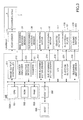
- FIG. 3 is a block diagram of the control unit.
- a control unit 500 has a main control unit 500 A.
- the main control unit 500 A includes a central processing unit (CPU) 501 , a read-only memory (ROM) 502 , and a random access memory (RAM) 503 .
- the CPU 501 centrally controls the liquid ejector.
- the ROM 502 stores programs executed by the CPU 501 and other fixed data.
- the RAM 503 temporarily stores image data, etc.
- control unit 500 includes a host interface (I/F) 506 which enables transmission of data between a host (an information processing apparatus) 600 such as a personal computer (PC), an image output controller 511 which controls the recording head 4 , and an encoder analyzer 512 which analyzes detected signals provided from the main scanning encoder sensor 24 and the sub scanning encoder sensor 26 .
- host an information processing apparatus
- PC personal computer
- image output controller 511 which controls the recording head 4
- encoder analyzer 512 which analyzes detected signals provided from the main scanning encoder sensor 24 and the sub scanning encoder sensor 26 .
- control unit 500 includes a main scanning motor driver 513 which drives the main scanning motor 5 , a sub scanning motor driver 514 which drives the sub scanning motor 16 , and an input-output (I/O) 516 which enables transmission of data and signals between various types of sensors/actuators 517 .
- main scanning motor driver 513 which drives the main scanning motor 5
- sub scanning motor driver 514 which drives the sub scanning motor 16
- I/O input-output
- control unit 500 includes an ejection detector 531 which interprets (or detects) an electronic change that occurs when a droplet lands onto the electrode plate 101 attached to the liquid ejecting detector 100 to determine whether or not a droplet is ejected. Furthermore, the control unit 500 includes a cleaning unit driver 532 which drives a driving motor 203 of the cleaning unit 200 that wipes the electrode plate 101 attached to the liquid ejecting detector 100 .
- the image output controller 511 includes a data generator which generates image data, a driving waveform generator which generates driving waveforms to control the recording head 4 , and a data transmitter which transmits image data and head controlling signals for selecting desired driving signals from the driving waveforms.
- the image output controller 511 transmits driving waveforms, head controlling signals, and image data to a head driver 510 which is a head driving circuit to drive the recording head 4 mounted on the carriage 3 , so that the nozzles of the recording head 4 eject droplets according to the image data.
- the encoder analyzer 512 has a direction detector 520 which detects moving directions based on detected signals and a counter 521 which detects moving amounts.
- the control unit 500 controls the main scanning motor 5 using the main scanning motor driver 513 based on an analysis outcome provided from the encoder analyzer 512 , thereby controlling the movement of the carriage 3 . Furthermore, the control unit 500 controls the sub scanning motor 16 using the sub scanning motor driver 514 , thereby controlling conveyance of the sheet 10 .
- the main control unit 500 A of the control unit 500 moves the recording head 4 when a detection of droplet ejection is performed.
- the main control unit 500 A causes the recording head 4 to eject droplets from predetermined nozzles in order to detect a condition of droplet ejection based on the detected signals provided from the ejection detector 531 .
- FIG. 4 is a side view of the liquid ejecting detector 100 and the carriage 3 .
- FIG. 5A is a perspective view of the liquid ejecting detector 100 and the carriage 3 .
- FIG. 5B is a perspective view of the liquid ejecting detector 100 and the carriage 3 when the wiper 202 is wiping the liquid ejecting detector 100 .
- FIG. 6 is a front view of the liquid ejecting detector 100 and the carriage 3 .
- FIG. 7 is a perspective view of the liquid ejecting detector 100 .
- FIG. 8 is a perspective view of a wiper retraction cover 204 .
- the liquid ejecting detector 100 has the electrode plate 101 , which has a droplet landing surface, on the upper surface of a holder 103 where the electrode plate 101 can face the nozzle surface 41 of the recording head 4 .
- the top surface (a facing surface) of the electrode plate 101 is the droplet landing surface.
- the holder 103 is made of an insulating material, such as plastic.
- the electrode plate 101 is a conductive metal and preferably made of a material resistant to rust and ink.
- the electrode plate 101 material may be a stainless steel (SUS304), a copper alloy coated with nickel (Ni), or a copper alloy coated with palladium (Pd).
- the droplet landing surface of the electrode plate 101 is preferably water-repellent coated.
- the electrode plate 101 is connected to the ejection detector 531 through an electrical connection using a lead 102 .
- the ejection detector 531 is explained hereinafter.
- the holder 103 has an opening 110 at the terminative end of the wiping direction of the wiper 202 .
- a part (a scraping part) of the rim of the opening 110 is a wiper cleaner 111 which serves as a cleaner to remove waste liquid (droplets adhered to the wiper 202 ) from the wiper 202 .
- the holder member 103 has a waste liquid tube 112 which is a passage from the bottom of the opening 110 to a waste liquid tank (not illustrated in the drawing).
- a suction pump (not illustrated in the drawing) is installed in the passage leading to the waste liquid tank, so that waste liquid accumulated in the bottom of the opening 110 is discharged to the waste liquid tank using the suction pump.
- the carriage 3 has the cleaning unit 200 which serves as a cleaner, and the cleaning unit 200 includes the wiper 202 which wipes droplets off the top surface (the droplet landing surface) of the electrode plate 101 while moving in the aligning direction of the nozzles.
- the wiper 202 is made of, for example, an ethylene propylene diene monomer rubber (EPDM). Water repellency of EPDM is not so high, so that the surface of the electrode plate 101 may have higher water repellency, compared to the wiper 202 . When the surface of the electrode plate 101 has higher water repellency, compared to the wiper 202 , ink is easily wiped off the electrode plate 101 .
- EPDM ethylene propylene diene monomer rubber
- the wiper 202 is attached to a timing belt 223 which circulates around a driving pulley 221 and a driven pulley 222 .
- a driving motor 203 attached to the carriage 3 drives the driving pulley 221 through the intermediaries of a worm gear 224 and a gear 225 . In this way, the wiper 202 moves in the direction of an arrow in FIG. 4 along with the circulation of the timing belt 223 .
- the cleaning unit 200 has the wiper retraction cover 204 which covers the wiper 202 at a retracted position.
- the wiper 202 is retracted inside the wiper retraction cover 204 , in order to prevent a slight amount of waste liquid adhered to the wiper 202 from being scattered during operation of the carriage 3 .
- the bottom surface of the wiper retraction cover 204 serves as a waste liquid receptacle 204 a which receives waste liquid that drips from the wiper 202 .
- an absorber 207 is provided on the waste liquid receptacle 204 a in order to absorb and retain waste liquid.
- the ejection detector 531 has a high-voltage supply 701 which applies high voltage VE (e.g., 750 V) to the electrode plate 101 .
- the main control unit 500 A controls on/off state of the high-voltage supply 701 .
- the ejection detector 531 includes a bandpass filter (BPF) 702 which inputs a signal corresponding to an electronic change that occurs when a droplet lands onto the electrode plate 101 , an amplifier (AMP) 703 which amplifies the signal, and an analog-digital convertor (ADC) 704 which converts the amplified signal from analog format to digital format.
- BPF bandpass filter
- AMP amplifier
- ADC analog-digital convertor
- the nozzle surface 41 of the recording head 4 is facing the electrode plate 101 when a detection of droplet ejection is performed. Then, high voltage VE is applied to the electrode plate 101 , so that an electric potential difference is provided between the nozzle surface 41 and the electrode plate 101 .
- the electrode plate 101 is positively charged (positive voltage) and the nozzle surface 41 of the recording head 4 is negatively charged (negative voltage).
- the recording head 4 ejects one or more liquid droplets for detection from each nozzle in order.
- the droplet which is ejected from one of the negatively charged nozzles of the recording head 4 , is also negatively charged.
- the high voltage VE applied to the electrode plate 101 slightly changes.
- the BPF 702 extracts the changed amount (alternating-current (AC) component).
- the extracted changed amount is amplified in the AMP 703 and converted in the ADC 704 from analog format to digital format.
- the changed amount converted in this way is entered to the main control unit 500 A as a measurement result (detection result).
- the main control unit 500 A determines whether or not the measurement result (the changed amount) is greater than the predetermined threshold value. In a case that the measurement outcome is greater than the threshold value, the main control unit 500 A determines that the droplet is ejected (ejected). On the other hand, in a case that the measurement result is not greater than the threshold value, the main control unit 500 A determines that the droplet is not ejected (not ejected).
- ejected/not ejected determination of a nozzle takes 0.5 to 10 msec in the case that droplets are ejected to the electrode plate 101 from each nozzle in order. After all nozzles are determined to be either ejected or not ejected, the high voltage VE applied to the electrode plate 101 is turned off.
- FIGS. 9A through 9C are perspective views of the liquid ejecting detector for explaining the wiping action.
- the driving motor 203 of the cleaning unit 200 is driven to move the wiper 202 .
- the wiper 202 wipes off ink 120 that is ejected onto the electrode plate 101 attached to the liquid ejecting detector 100 , as illustrated in FIG. 9A .
- the wiper 202 is moved relative to the wiper cleaner 111 , so that the wiper cleaner 111 scrapes off the ink adhered to the wiper 202 to clean the wiper 202 .
- FIGS. 10A, 10B, 11A, and 11B are drawings illustrating cleaning performances of the liquid ejecting detector 100 .
- FIGS. 11A and 11B are drawings illustrating the conditions of the waste ink accumulation caused by the cleaning of the wiper 202 .
- waste ink is adhered to the surface (the wiping surface) of the wiper 202 after the wiper 202 wipes off the ink 120 .
- waste ink is accumulated on the wiper cleaner 111 in the areas which correspond to the side ends of the wiper 202 .
- the accumulated waste ink may be attached to the nozzle surface 41 of the recording head 4 of the carriage 3 , which goes back and forth above the accumulated waste ink. Furthermore, the accumulated waste ink may cause contamination of a conveyed sheet or the conveying pathway.
- the accumulated waste ink may be retransferred to the wiper 202 .
- Retransferred accumulated waste ink may be attached to the electrode plate 101 at the time of the next cleaning action of the electrode plate 101 .
- the accumulated waste ink may be rubbed by the recording head 4 , which may cause an image defect.
- FIG. 12 is a perspective view of the liquid ejecting detector 100 according to the first embodiment.
- FIG. 13A is a plan view of the liquid ejecting detector 100
- FIG. 13B is a side view of the liquid ejecting detector 100
- FIG. 13C is a front view of the liquid ejecting detector 100 .
- the scraper 111 a which has a contact surface where the wiper 202 makes contact with the wiper cleaner 111 , is in a curved shape so that the central part has a convex shape toward the wiping direction.
- the scraper 111 a of the wiper cleaner 111 is in such a shape as the wiper 202 makes contact gradually from the side ends to the center in the direction perpendicular to the wiping direction of the wiper 202 .
- the wiper 202 with waste ink moves in the wiping direction. Then, as illustrated in FIG. 14B , the side ends of the wiper 202 make contact with the scraper 111 a (the contact surface) of the wiper cleaner 111 .
- the surface of the wiper 202 gradually makes contact with the scraper 111 a (the contact surface) of the wiper cleaner 111 as the wiper 202 shape changes by elastic deformation.
- the waste ink adhered to the wiper 202 is collected from the side ends to the inside (the center). In this way, the waste ink does not run off the side ends of the wiper 202 .
- the waste ink does not accumulate in the areas of the wiper cleaner 111 that correspond to the side ends of the wiper 202 . Therefore, contamination of a sheet and the conveying pathway with accumulated waste ink is prevented and good cleaning quality of the wiper 202 is sustained for a long period of time.
- FIG. 15 is a plan view of the wiper 202 and the cleaner according to the second embodiment.
- the relationship is defined between the curve of the wiper 202 while changing shape by elastic deformation and the curve of the scraper 111 a of the wiper cleaner 111 .
- the radius of an arc formed by the contact surface of the wiper 202 , when the wiper 202 makes contact with the wiper cleaner 111 (the cleaner) and receives pressure, is indicated as R 1 .
- the pressure from the wiper cleaner 111 causes gradual elastic deformation of the wiper 202 .
- the side ends of the wiper 202 touch the wiper cleaner 111 first, and then the central part is curved toward the wiping direction.
- the degree of curve that the wiper 202 can make is dependent on a material and a figure, such as a thickness and a length, of the wiper 202 .
- the radius R 1 of the arc formed by the contact surface of the wiper 202 when the wiper 202 is curved to the fullest extent is indicated as R 1 max.
- the radius of the arc of the scraper 111 a (the contact surface) of the wiper cleaner 111 is indicated as R 2 .
- the material and the figure such as the thickness and the length of the wiper 202 is predetermined so as to maintain an R 2 >R 1 max relationship. That is to say, the part (the scraper 111 a ) of the cleaner that makes contact with the wiper 202 is in a shape of an ark having a bigger curvature radius than the curvature radius of the arc formed by the wiper 202 curved to the fullest extent.
- the entire area of the contact surface of the wiper 202 surely makes contact with the scraper 111 a of the wiper cleaner 111 , which enables the entire area of the contact surface of the wiper 202 to be surely cleaned.
- FIG. 16 is a perspective view of the liquid ejecting detector 100 according to the third embodiment.
- multiple wiper cleaners 111 and 111 are arranged in the moving direction (the wiping direction) of the wiper 202 . Therefore, after waste ink adhered to the wiper 202 is scraped off with the scraper 111 a of the wiper cleaner 111 in the upstream of the moving direction, the waste ink is scraped off with the scraper 111 b of the wiper cleaner 111 in the downstream of the moving direction. In this way, the cleaning quality of one cleaning action is enhanced.
- FIG. 17 is a plan view of the wiper cleaner 111 according to the fourth embodiment.
- the curve of the scraper 111 b in the downstream of the moving direction (the wiping direction) of the wiper 202 is milder than the curve of the scraper 111 a in the upstream (the curvature is smaller).
- the curvature radius of the contact surface of the scraper 111 b in the downstream is bigger than the curvature radius of the contact surface of the scraper 111 a in the upstream.
- the curve of the scraper 111 b of the wiper cleaner 111 in the downstream of the moving direction of the wiper 202 is milder than the curve of the scraper 111 a of the wiper cleaner 111 in the upstream.
- the side ends of the wiper 202 make contact first with the wiper cleaner 111 . Then even when the wiper 202 is curved so that the entire area of the wiper 202 makes contact with the scraper 111 a of the wiper cleaner 111 , the contact pressure between the scraper 111 a and the wiper 202 is higher in the areas close to the side ends of the wiper 202 .
- waste ink in the area close to the side ends of the wiper 202 is easily scraped off, compared to the area close to the center of the wiper 202 , which means, relatively speaking, that waste ink is more likely to remain in the area close to the center of the wiper 202 .
- the curve of the scraper 111 b of the wiper cleaner 111 in the downstream is milder, or almost straight, so that higher contact pressure is applied in the area close to the center of the wiper 202 . In this way, waste ink in the area close to the center of the wiper 202 is surely scraped off as well, which ensures that the entire area of the wiper 202 gets cleaned.
- FIG. 18 is a perspective view of the liquid ejecting detector 100 according to the fifth embodiment.
- FIG. 19 is a front view of the liquid ejecting detector 100 according to the fifth embodiment.
- the wiper cleaner 111 has a sloping surface 111 c and a sloping surface 111 d respectively on the other side of the scraper 111 a and the scraper 111 b (in the downstream of the moving direction of the wipers), which incline in such an angle as the contact pressure of the wiper 202 gradually decreases.
- waste ink may remain on the wiper 202 even after the wiper cleaner 111 cleans the wiper 202 .
- the wiper 202 immediately recovers from the curved state to the original state, the remaining waste ink may be scattered.
- the sloping surface 111 c and the sloping surface 111 d are provided respectively in the downstream of the scraper 111 a and the scraper 111 b , so that the curving degree of the wiper 202 is reduced by the time that the wiper 202 gets away from the wiper cleaner 111 , compared to the time that the wiper 202 is on the top surface of the wiper cleaner 111 .
- a resistor (a resistor member) may be provided with a droplet landing surface, so that the ejection detection is performed based on a change of resistance value between terminals caused by landing of a droplet.
- the term “sheet” is not limited to a sheet of paper but includes a sheet of overhead projector (OHP), cloth, glass, circuit board, etc.
- OHP overhead projector
- the term “sheet” may be used for anything that liquid such as ink droplet, etc., can be attached onto, including what is called recording-object medium, recording medium, recording paper, and recording sheet, etc.
- image forming”, “recording”, “letter printing”, “image printing”, and “printing”, are all considered to be equivalent.
- liquid ejector refers to an apparatus which ejects liquid in order to form an image on a medium including paper, string, fiber, silk, leather, metal, plastic, glass, wood, ceramic, etc.
- image forming not only means to provide on a medium an image with meanings such as a character and a figure, but also means to provide on a medium an image without meanings such as a pattern (or simply causing a droplet to land on a medium).
- the term “ink” is not limited to what is caked ink unless otherwise specified, and is used as a collective term referring to any types of liquid that can be used for an image forming, such as what is called recording liquid, fixing liquid, liquid, etc. Therefore, the term “ink” includes a DNA sample, resist, pattern material, resin, etc.
- image is not limited to a two-dimensional image but includes an image applied to a three-dimensional object and a three dimensional object itself formed as a three-dimensional figure.
Landscapes
- Ink Jet (AREA)
Applications Claiming Priority (3)
| Application Number | Priority Date | Filing Date | Title |
|---|---|---|---|
| JP2014-033299 | 2014-02-24 | ||
| JP2014033299 | 2014-02-24 | ||
| PCT/JP2015/054226 WO2015125762A1 (ja) | 2014-02-24 | 2015-02-17 | 画像形成装置及び吐出検知ユニット |
Related Parent Applications (1)
| Application Number | Title | Priority Date | Filing Date |
|---|---|---|---|
| PCT/JP2015/054226 Continuation WO2015125762A1 (ja) | 2014-02-24 | 2015-02-17 | 画像形成装置及び吐出検知ユニット |
Publications (2)
| Publication Number | Publication Date |
|---|---|
| US20160325550A1 US20160325550A1 (en) | 2016-11-10 |
| US9694584B2 true US9694584B2 (en) | 2017-07-04 |
Family
ID=53878264
Family Applications (1)
| Application Number | Title | Priority Date | Filing Date |
|---|---|---|---|
| US15/217,088 Active US9694584B2 (en) | 2014-02-24 | 2016-07-22 | Liquid ejector and liquid ejecting detector |
Country Status (7)
| Country | Link |
|---|---|
| US (1) | US9694584B2 (enExample) |
| EP (1) | EP3112158B1 (enExample) |
| JP (1) | JP6156570B2 (enExample) |
| CN (1) | CN106068184B (enExample) |
| BR (1) | BR112016019129B1 (enExample) |
| RU (1) | RU2639064C1 (enExample) |
| WO (1) | WO2015125762A1 (enExample) |
Families Citing this family (12)
| Publication number | Priority date | Publication date | Assignee | Title |
|---|---|---|---|---|
| US10226929B2 (en) | 2016-11-10 | 2019-03-12 | Ricoh Company, Ltd. | Head cleaner, maintenance device, and liquid discharge apparatus |
| JP6988505B2 (ja) | 2017-03-17 | 2022-01-05 | 株式会社リコー | 液体吐出装置、及び吸引装置 |
| JP2017149159A (ja) * | 2017-05-01 | 2017-08-31 | キヤノンファインテックニスカ株式会社 | インクジェット記録装置 |
| JP7059640B2 (ja) | 2018-01-15 | 2022-04-26 | 株式会社リコー | 液体吐出ヘッド、液体吐出ユニット、液体を吐出する装置 |
| JP7085132B2 (ja) | 2018-09-07 | 2022-06-16 | 株式会社リコー | ロールユニット、ロール装置、ヘッドメンテナンス装置、液体を吐出する装置 |
| JP7238417B2 (ja) | 2019-01-18 | 2023-03-14 | 株式会社リコー | 定着装置、画像形成装置、定着方法、及びプログラム |
| JP2020189450A (ja) | 2019-05-22 | 2020-11-26 | 株式会社リコー | キャップ、ヘッドメンテナンス装置、液体を吐出する装置 |
| US11433675B2 (en) | 2020-06-17 | 2022-09-06 | Ricoh Company, Ltd. | Maintenance device and liquid discharge apparatus |
| JP7558772B2 (ja) * | 2020-11-27 | 2024-10-01 | 理想科学工業株式会社 | ワイパ機構 |
| JP7589084B2 (ja) * | 2021-03-24 | 2024-11-25 | 理想科学工業株式会社 | ワイピング装置 |
| JP7694089B2 (ja) | 2021-03-25 | 2025-06-18 | 株式会社リコー | 液体を吐出する装置、液体収容容器、詰め替え容器、洗浄液容器 |
| JP7689656B2 (ja) | 2021-03-25 | 2025-06-09 | 株式会社リコー | 液体を吐出する装置、液体収容容器、洗浄液容器 |
Citations (13)
| Publication number | Priority date | Publication date | Assignee | Title |
|---|---|---|---|---|
| JPH09131885A (ja) | 1995-10-20 | 1997-05-20 | Lexmark Internatl Inc | 印刷ヘッド・ワイパ清浄ゾーンを具備するインク・ジェット印刷ヘッド及び同印刷ヘッドを有する印刷装置 |
| JP2002079680A (ja) | 2000-09-05 | 2002-03-19 | Ricoh Co Ltd | 記録ヘッド及びインクジェット記録装置 |
| JP2004306475A (ja) | 2003-04-08 | 2004-11-04 | Seiko Epson Corp | 液滴不吐出検出装置および液滴吐出装置 |
| JP2008114507A (ja) | 2006-11-06 | 2008-05-22 | Seiko Epson Corp | ヘッドメンテナンス装置、ヘッドメンテナンス方法及びそれを用いたインクジェットプリンタ |
| JP2009279765A (ja) | 2008-05-19 | 2009-12-03 | Seiko Epson Corp | 液体噴射装置 |
| JP2010046962A (ja) | 2008-08-22 | 2010-03-04 | Ricoh Co Ltd | 液体吐出装置及びこれを備えた画像形成装置 |
| JP4735120B2 (ja) | 2005-08-15 | 2011-07-27 | セイコーエプソン株式会社 | 印刷ヘッド検査装置およびこれを搭載する印刷装置並びに印刷ヘッド検査方法,これに用いるプログラム |
| US20130083123A1 (en) * | 2011-09-30 | 2013-04-04 | Brother Kogyo Kabushiki Kaisha | Liquid ejection apparatus and wiping method |
| JP2014097642A (ja) * | 2012-11-15 | 2014-05-29 | Ricoh Co Ltd | 画像形成装置 |
| US20140210908A1 (en) * | 2013-01-31 | 2014-07-31 | Canon Finetech Inc. | Ink jet printing apparatus |
| US8919921B2 (en) | 2012-11-15 | 2014-12-30 | Ricoh Company, Ltd. | Image forming apparatus |
| US8967759B2 (en) | 2013-03-07 | 2015-03-03 | Ricoh Company, Ltd. | Image forming apparatus |
| JP2015074106A (ja) | 2013-10-07 | 2015-04-20 | 株式会社リコー | 画像形成装置 |
Family Cites Families (8)
| Publication number | Priority date | Publication date | Assignee | Title |
|---|---|---|---|---|
| US6409303B1 (en) * | 2000-03-31 | 2002-06-25 | Hewlett-Packard Company | Two-stage scraper system for inkjet wipers |
| JP2004207485A (ja) * | 2002-12-25 | 2004-07-22 | Seiko Epson Corp | ノズル詰まり検出装置、液滴吐出装置、電気光学装置、電気光学装置の製造方法及び電子機器 |
| KR100622177B1 (ko) * | 2003-02-28 | 2006-09-08 | 세이코 엡슨 가부시키가이샤 | 액적 토출 장치 및 토출 이상 회복 방법 |
| JP2005161838A (ja) * | 2003-11-10 | 2005-06-23 | Seiko Epson Corp | 液滴吐出方法、液滴吐出装置、ノズル異常判定方法、表示装置、および電子機器 |
| JP5145822B2 (ja) * | 2007-08-20 | 2013-02-20 | セイコーエプソン株式会社 | 噴射検査装置、印刷装置及び噴射検査方法 |
| JP2010064309A (ja) * | 2008-09-09 | 2010-03-25 | Seiko Epson Corp | 液体吐出装置、及び、吐出検査方法 |
| JP2012035440A (ja) * | 2010-08-04 | 2012-02-23 | Ricoh Co Ltd | 画像形成装置 |
| JP5732899B2 (ja) * | 2011-02-22 | 2015-06-10 | セイコーエプソン株式会社 | ノズル状態検出装置および画像形成装置 |
-
2015
- 2015-02-17 CN CN201580009414.3A patent/CN106068184B/zh not_active Expired - Fee Related
- 2015-02-17 RU RU2016133750A patent/RU2639064C1/ru not_active IP Right Cessation
- 2015-02-17 BR BR112016019129-3A patent/BR112016019129B1/pt not_active IP Right Cessation
- 2015-02-17 WO PCT/JP2015/054226 patent/WO2015125762A1/ja not_active Ceased
- 2015-02-17 EP EP15752602.1A patent/EP3112158B1/en not_active Not-in-force
- 2015-02-17 JP JP2016504100A patent/JP6156570B2/ja not_active Expired - Fee Related
-
2016
- 2016-07-22 US US15/217,088 patent/US9694584B2/en active Active
Patent Citations (15)
| Publication number | Priority date | Publication date | Assignee | Title |
|---|---|---|---|---|
| US5905513A (en) | 1995-10-20 | 1999-05-18 | Lexmark International, Inc. | Ink jet printhead body having wiper cleaning zones located on both sides of printhead |
| JPH09131885A (ja) | 1995-10-20 | 1997-05-20 | Lexmark Internatl Inc | 印刷ヘッド・ワイパ清浄ゾーンを具備するインク・ジェット印刷ヘッド及び同印刷ヘッドを有する印刷装置 |
| JP2002079680A (ja) | 2000-09-05 | 2002-03-19 | Ricoh Co Ltd | 記録ヘッド及びインクジェット記録装置 |
| JP2004306475A (ja) | 2003-04-08 | 2004-11-04 | Seiko Epson Corp | 液滴不吐出検出装置および液滴吐出装置 |
| JP4735120B2 (ja) | 2005-08-15 | 2011-07-27 | セイコーエプソン株式会社 | 印刷ヘッド検査装置およびこれを搭載する印刷装置並びに印刷ヘッド検査方法,これに用いるプログラム |
| JP2008114507A (ja) | 2006-11-06 | 2008-05-22 | Seiko Epson Corp | ヘッドメンテナンス装置、ヘッドメンテナンス方法及びそれを用いたインクジェットプリンタ |
| JP2009279765A (ja) | 2008-05-19 | 2009-12-03 | Seiko Epson Corp | 液体噴射装置 |
| JP2010046962A (ja) | 2008-08-22 | 2010-03-04 | Ricoh Co Ltd | 液体吐出装置及びこれを備えた画像形成装置 |
| US20130083123A1 (en) * | 2011-09-30 | 2013-04-04 | Brother Kogyo Kabushiki Kaisha | Liquid ejection apparatus and wiping method |
| JP2014097642A (ja) * | 2012-11-15 | 2014-05-29 | Ricoh Co Ltd | 画像形成装置 |
| US8919921B2 (en) | 2012-11-15 | 2014-12-30 | Ricoh Company, Ltd. | Image forming apparatus |
| US20140210908A1 (en) * | 2013-01-31 | 2014-07-31 | Canon Finetech Inc. | Ink jet printing apparatus |
| US8967759B2 (en) | 2013-03-07 | 2015-03-03 | Ricoh Company, Ltd. | Image forming apparatus |
| JP2015074106A (ja) | 2013-10-07 | 2015-04-20 | 株式会社リコー | 画像形成装置 |
| US9028039B2 (en) | 2013-10-07 | 2015-05-12 | Ricoh Company, Ltd. | Image forming apparatus |
Non-Patent Citations (2)
| Title |
|---|
| International Search Report Issued on Apr. 21, 2015 in PCT/JP2015/054226 filed on Feb. 17, 2015 (with English Translation). |
| Takeuchi Shotaro, MachineTranslationofJP 2014097642 A, 2012. * |
Also Published As
| Publication number | Publication date |
|---|---|
| RU2639064C1 (ru) | 2017-12-19 |
| US20160325550A1 (en) | 2016-11-10 |
| BR112016019129B1 (pt) | 2022-02-22 |
| EP3112158A1 (en) | 2017-01-04 |
| JPWO2015125762A1 (ja) | 2017-03-30 |
| JP6156570B2 (ja) | 2017-07-05 |
| WO2015125762A1 (ja) | 2015-08-27 |
| EP3112158B1 (en) | 2018-10-17 |
| CN106068184B (zh) | 2017-11-14 |
| CN106068184A (zh) | 2016-11-02 |
| EP3112158A4 (en) | 2017-09-13 |
| BR112016019129A2 (enExample) | 2017-08-15 |
Similar Documents
| Publication | Publication Date | Title |
|---|---|---|
| US9694584B2 (en) | Liquid ejector and liquid ejecting detector | |
| JP6295582B2 (ja) | 画像形成装置 | |
| JP6232861B2 (ja) | 画像形成装置及び吐出検知装置 | |
| US9533496B2 (en) | Apparatus for ejecting liquids, ejection detection apparatus, and ejection detector | |
| CN102189768B (zh) | 打印装置、打印装置的维护方法 | |
| JP6142581B2 (ja) | 画像形成装置 | |
| JP4935056B2 (ja) | 印刷ヘッド検査装置、印刷装置、印刷ヘッド検査方法及びそのプログラム | |
| JP2014097642A (ja) | 画像形成装置 | |
| JP4946012B2 (ja) | 画像形成装置、印刷ヘッド検査方法及びそのプログラム | |
| JP6519121B2 (ja) | 画像形成装置、吐出検知ユニット、液体吐出装置 | |
| JP4371060B2 (ja) | 画像形成装置 | |
| JP5732918B2 (ja) | クリーニング装置及び画像形成装置 | |
| US20060157579A1 (en) | Nozzle cleaning method, nozzle cleaning device, liquid ejection apparatus, printing apparatus and computer-readable medium | |
| JP6237302B2 (ja) | 画像形成装置 | |
| JP6613726B2 (ja) | 液体を吐出する装置 | |
| JP6142559B2 (ja) | 画像形成装置 | |
| JP6455291B2 (ja) | 液体を吐出する装置 | |
| JP2010201853A (ja) | 吐出検査装置、流体吐出装置及び吐出検査方法 | |
| JP2016087927A (ja) | 画像形成装置、吐出検知装置及び吐出検知ユニット | |
| JP2015150814A (ja) | 画像形成装置 | |
| JP2017052131A (ja) | 液体を吐出する装置、プログラム、吐出検知方法 |
Legal Events
| Date | Code | Title | Description |
|---|---|---|---|
| AS | Assignment |
Owner name: RICOH COMPANY, LTD., JAPAN Free format text: ASSIGNMENT OF ASSIGNORS INTEREST;ASSIGNORS:MASAOKA, SHINGO;TAKEUCHI, SHOTARO;HISADA, MASAHIKO;AND OTHERS;REEL/FRAME:039235/0115 Effective date: 20160721 |
|
| STCF | Information on status: patent grant |
Free format text: PATENTED CASE |
|
| MAFP | Maintenance fee payment |
Free format text: PAYMENT OF MAINTENANCE FEE, 4TH YEAR, LARGE ENTITY (ORIGINAL EVENT CODE: M1551); ENTITY STATUS OF PATENT OWNER: LARGE ENTITY Year of fee payment: 4 |
|
| MAFP | Maintenance fee payment |
Free format text: PAYMENT OF MAINTENANCE FEE, 8TH YEAR, LARGE ENTITY (ORIGINAL EVENT CODE: M1552); ENTITY STATUS OF PATENT OWNER: LARGE ENTITY Year of fee payment: 8 |