US8992671B2 - Machining method for workpiece using a machining device with waste collection equipment - Google Patents
Machining method for workpiece using a machining device with waste collection equipment Download PDFInfo
- Publication number
- US8992671B2 US8992671B2 US12/737,866 US73786610A US8992671B2 US 8992671 B2 US8992671 B2 US 8992671B2 US 73786610 A US73786610 A US 73786610A US 8992671 B2 US8992671 B2 US 8992671B2
- Authority
- US
- United States
- Prior art keywords
- waste
- machining
- water
- collection
- antistatic treatment
- Prior art date
- Legal status (The legal status is an assumption and is not a legal conclusion. Google has not performed a legal analysis and makes no representation as to the accuracy of the status listed.)
- Active, expires
Links
Images


Classifications
-
- B—PERFORMING OPERATIONS; TRANSPORTING
- B23—MACHINE TOOLS; METAL-WORKING NOT OTHERWISE PROVIDED FOR
- B23Q—DETAILS, COMPONENTS, OR ACCESSORIES FOR MACHINE TOOLS, e.g. ARRANGEMENTS FOR COPYING OR CONTROLLING; MACHINE TOOLS IN GENERAL CHARACTERISED BY THE CONSTRUCTION OF PARTICULAR DETAILS OR COMPONENTS; COMBINATIONS OR ASSOCIATIONS OF METAL-WORKING MACHINES, NOT DIRECTED TO A PARTICULAR RESULT
- B23Q11/00—Accessories fitted to machine tools for keeping tools or parts of the machine in good working condition or for cooling work; Safety devices specially combined with or arranged in, or specially adapted for use in connection with, machine tools
- B23Q11/0042—Devices for removing chips
- B23Q11/005—Devices for removing chips by blowing
-
- B—PERFORMING OPERATIONS; TRANSPORTING
- B23—MACHINE TOOLS; METAL-WORKING NOT OTHERWISE PROVIDED FOR
- B23Q—DETAILS, COMPONENTS, OR ACCESSORIES FOR MACHINE TOOLS, e.g. ARRANGEMENTS FOR COPYING OR CONTROLLING; MACHINE TOOLS IN GENERAL CHARACTERISED BY THE CONSTRUCTION OF PARTICULAR DETAILS OR COMPONENTS; COMBINATIONS OR ASSOCIATIONS OF METAL-WORKING MACHINES, NOT DIRECTED TO A PARTICULAR RESULT
- B23Q11/00—Accessories fitted to machine tools for keeping tools or parts of the machine in good working condition or for cooling work; Safety devices specially combined with or arranged in, or specially adapted for use in connection with, machine tools
- B23Q11/0042—Devices for removing chips
- B23Q11/0057—Devices for removing chips outside the working area
-
- Y—GENERAL TAGGING OF NEW TECHNOLOGICAL DEVELOPMENTS; GENERAL TAGGING OF CROSS-SECTIONAL TECHNOLOGIES SPANNING OVER SEVERAL SECTIONS OF THE IPC; TECHNICAL SUBJECTS COVERED BY FORMER USPC CROSS-REFERENCE ART COLLECTIONS [XRACs] AND DIGESTS
- Y02—TECHNOLOGIES OR APPLICATIONS FOR MITIGATION OR ADAPTATION AGAINST CLIMATE CHANGE
- Y02P—CLIMATE CHANGE MITIGATION TECHNOLOGIES IN THE PRODUCTION OR PROCESSING OF GOODS
- Y02P70/00—Climate change mitigation technologies in the production process for final industrial or consumer products
- Y02P70/10—Greenhouse gas [GHG] capture, material saving, heat recovery or other energy efficient measures, e.g. motor control, characterised by manufacturing processes, e.g. for rolling metal or metal working
Definitions
- This invention relates to a machining device with waste collection equipment and a machining method for a workpiece using the machining device, and relates particularly to a machining device with waste collection equipment, which is suitable for collecting waste constituted of an easily charged synthetic resin or a metal powder, for example, and a machining method for a workpiece using the machining device.
- the dust collection device 410 is characterized by including the water vapor supply means 414 for supplying the water vapor 414 C to the gas and a cooling means 416 provided on the downstream side of the water vapor supply means 414 for cooling the gas supplied with water vapor by the water vapor supply means 414 .
- the dust collection attachment 501 is characterized as follows. Namely, the dust collection attachment 501 has a plurality of bellows portions 502 b and 502 d .
- a tubular cover portion 502 surrounding a hammer 510 b of a chipping hammer 510 for becoming a negative pressure by air suction and an intake pipe portion 503 for sucking the inside of the cover portion 502 and collecting dust are connected between the plurality of bellows portions 502 b and 502 d.
- the airbag tear line forming device 200 described in the Patent Document 1 is provided with no device for collecting waste generated by cutting processing. Therefore, since waste remaining on a formed tear line becomes an obstacle, there is a problem that it is difficult to accurately measure a depth of the tear line (fracture groove) using an optical measurement device such as a laser displacement gauge. Especially, because of the influence of waste generated in large numbers, it is practically difficult to measure the depth of the tear line quickly and highly accurately while the cutting processing is performed and at the same time, adjust the cutting state with which the value of the depth of the tear line is fed back.
- the dust collection and air purification equipment 301 described in the Patent Document 2 is characterized in that because of its structure, the water storage tank is provided in the lower portion of the dust collection tank so that ultrafine dust is collected as sludge.
- the water storage tank is provided in the lower portion of the dust collection tank so that ultrafine dust is collected as sludge.
- the dust collection and air purification equipment 301 described in the Patent Document 2 is intended to collect only ultrafine dust (with an average diameter of 0.1 to 0.3 ⁇ m) generated when teeth is cut, for example, but is not intended to simply and efficiently collect waste generated in large numbers by a machining device, easily charged, and having a considerably large size.
- the dust collection device 410 described in the Patent Document 3 is intended to collect only ultrafine particles (with a grain diameter of 0.1 ⁇ m or less) which become a problem in the clean room, but is not intended to simply and efficiently collect waste generated in large numbers by a machining device, easily charged, and having a considerably large size.
- the dust collection attachment 501 described in the Patent Document 4 is intended to collect dust generated by the hummer 510 b which is a machining device but a predetermined antistatic treatment is not considered therefor. Accordingly, even if a cyclone, a collection tank, and so on are provided, static electricity is generated, and dust cannot be collected efficiently.
- a predetermined machining device is provided with waste collection equipment for collecting waste generated in large numbers by machining processing, easily charged, and having a considerably large size while applying a predetermined antistatic treatment to the waste, whereby even in the dry season like winter season when static electricity is likely generated, waste can be collected efficiently, and, at the same time, a machining state of a workpiece in the machining processing can be managed with high accuracy, so that the present invention has been completed.
- an object of this invention is to provide a machining device, which has high machining accuracy with respect to a workpiece, and, in addition, efficiently collects waste which is generated by machining processing and is easily charged, and a machining method for a workpiece using the machining device.
- a machining device with waste collection equipment which collects waste generated by a predetermined machining processing
- the waste collection equipment including: a transfer path through which the waste is transferred using an air flow; a water supply device which is provided at an intermediate portion of the transfer path and supplies a predetermined amount of water to the waste thereby applying antistatic treatment to the waste; a cyclone which applies separation processing to the waste subjected to the antistatic treatment; and a collection tank which collects the waste, subjected to the separation processing, by the cyclone, and the above problems can be solved.
- the water supply device is constituted of a venturi pipe and a water introduction pipe supplying water into the venturi pipe and supplies a predetermined amount of water through the water introduction pipe, utilizing a negative pressure generated when the air flow passes through the venturi pipe.
- the water supply amount in the water supply device can be more finely adjusted, and therefore, the antistatic treatment can be more efficiently applied to waste with a relatively small amount of water.
- a predetermined amount of water can be stored in the water introduction pipe between the valve and the water supply device, and therefore, a predetermined antistatic treatment can be quickly applied to waste, utilizing the water.
- the machining device is a cutting device or a polishing device, and after waste generated by the cutting device or the polishing device is subjected to the separation processing in the cyclone, the waste is collected in the collection tank.
- the antistatic treatment can be efficiently applied to even waste such as a cutting powder, which is generated in large numbers in the cutting device and so on, is easily charged, and has a relatively large size, and the waste can be efficiently collected in the collection tank through the cyclone.
- the collection tank comprises a transparent window portion, and a waste collection state can be visually confirmed.
- a waste collection level in the collection tank can be confirmed visually, and an antistatic state of waste and a waste collection period can be easily judged.
- a second collection part for collecting the waste is provided under the first collection part through a shutter, and when the shutter is opened, waste dropped by its own weight is integrally collected in the second collection part.
- Another aspect of this invention provides a machining method for a workpiece using a machining device with waste collection equipment.
- the machining method is characterized by including the following processes (1) to (5):
- a volume resistance before the antistatic treatment in the waste is 1 ⁇ 10 8 ⁇ cm or more, and the volume resistance after the antistatic treatment in the waste is 1 ⁇ 10 6 ⁇ cm or less.
- the volume resistance of waste can be measured using a digital volt meter under a predetermined condition (electrode of 1 cm 2 , voltage of 100 V, and resistance value conversion after application of voltage for 30 seconds) according to a four-terminal method.
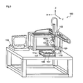
- FIG. 1 is a schematic view for explaining waste collection equipment according to the present invention
- FIGS. 3A and 3B are views for schematically explaining an operation of the machining device provided with a cutting device (end mill) and a cutting device (ultrasonic cutter);
- FIGS. 4A and 4B are views for explaining an aspect of an airbag device
- FIG. 5 is a view for schematically explaining an airbag fracture groove forming device
- FIGS. 6A to 6C are views for explaining an aspect of a water supply device
- FIG. 7 is a view for explaining the related art airbag tear line forming device
- FIG. 8 is a view for explaining the related art dust collection and air purification equipment
- FIG. 9 is a view for explaining the related art dust collection device.
- FIG. 10 is a view for explaining the related art dust collection attachment.
- a machining device 12 is provided.
- the machining device 12 is provided with waste collection equipment 10 collecting waste generated by a predetermined machining processing.
- the machining device 12 including the waste collection equipment 10 is characterized in that the waste collection equipment 10 is provided with a transfer path 14 through which waste is transferred by airflow, a water supply device 16 which is provided at an intermediate portion of the transfer path 14 and applies antistatic treatment to the waste by supplying a predetermined amount of water to the waste, a cyclone 18 which applies separation processing to the waste subjected to the antistatic treatment, and a collection tank 24 which collects waste subjected to the separation processing by the cyclone 18 .
- FIG. 1 is a schematic view of the waste collection equipment 10 .
- FIG. 2 is a partially enlarged view of the machining device 12 including a part of the waste collection equipment 10 .
- a balloon in FIG. 2 shows an enlarged view of the machining device (cutting tool) 12 .
- A represents a machine processing section for performing a predetermined machining processing.
- B represents a charging section for applying a predetermined charge treatment to waste.
- C represents a collection section for collecting waste.
- an airbag fracture groove forming device for forming an airbag fracture groove (tear line) mainly to an automotive interior member (airbag door member).
- the type of the machining device (including a machinery tool) 12 exemplified in FIGS. 1 and 2 is not limited especially as long as it has a constitution in which waste is generated by a predetermined machining processing.
- the machining device may be at least one of a cutting device, a polishing device, a cutoff device, and a boring device, or these machining devices and other mechanical device such as an inspection device, a deposition device, a coating device, and a heating device may be combined.
- the cutting device includes an end mill, a vibration cutting device (including an ultrasonic vibration cutting device, an elliptical vibration cutting device, and the like), and a rotating shaft cutting device.
- a vibration cutting device including an ultrasonic vibration cutting device, an elliptical vibration cutting device, and the like
- a rotating shaft cutting device is a solid end mill having at its end a bottom blade and on its side a side blade.
- the polishing device includes a turning tool, a grinder, a blast, and a file.
- the cutoff device includes an ultrasonic cutter, a laser cutter, a thermal fusion blade, and the like.
- the boring device includes a drill (including a high-frequency ultrasonic drill), a reamer, a tap, and the like.
- the machining device is the airbag fracture groove forming device, as shown in FIGS. 3 A and 3 B
- the end mill 12 as a cutting device and the ultrasonic cutter 11 as a cutoff device are provided, whereby both the end mill 12 and the ultrasonic cutter 11 or one of them may be used according to a kind of a workpiece and intended use.
- the end mill 12 is used, and airbag fracture grooves having a rectangular cross-section can be continuously formed in a workpiece 15 .
- the ultrasonic cutter 11 is used, a plurality of cutoff portions may be provided, at predetermined intervals, indirectly to a bottom portion of the airbag fracture groove with a rectangular cross-section formed by the end mill 12 or directly to the workpiece 15 .
- FIG. 3A shows a machining state in which the end mill 12 is moved down to a lower position than a predetermined position by a position controller 13 ( 13 a , 13 b , 13 c ) for positioning in three-dimensional directions including vertical direction operation and rotating direction operation and a cylinder 12 d continued from the position controller 13 , and the airbag fracture grooves are continuously formed in the workpiece 15 .
- the ultrasonic cutter 11 provided on the opposite side of the end mill 12 through the position controller 13 is moved up to an upper position than a predetermined position so as not to inhibit the operation of the end mill 12 .
- FIG. 3B shows a machining state in which the ultrasonic cutter 11 ( 11 a , 11 b , 11 c ) is moved down to a lower position than a predetermined position by the position controller 13 , and the airbag fracture grooves are continuously formed in the workpiece 15 .
- the ultrasonic cutter 11 is constituted of an end portion 11 a , a shaft portion 11 b , and an ultrasonic vibration device 11 c.
- the end mill 12 provided on the opposite side of the ultrasonic cutter 11 through the position controller 13 is moved up to an upper position than a predetermined position so as not to inhibit the operation of the ultrasonic cutter 11 .
- the machining device such as a cutting device, a polishing device, a cutoff device, and a boring device according to an aspect of a workpiece.
- an airbag door member 40 includes a single-layered base material 15 formed of such as a polypropylene resin or an ABS resin, while an airbag fracture groove 15 d substantially constituted of a continuous line is formed in the base material 15 , using only a cutting device (end mill), generated waste can be suctioned and removed.
- a cutting device end mill
- the machining state (the depth of the fracture groove) of the base material 15 is monitored online by a laser displacement gauge 12 e (for example, LKG-5000 Series from Keyence Corporation) to be fed back, whereby the depth of the fracture groove of the base material 15 can be adjusted within a predetermined range.
- a laser displacement gauge 12 e for example, LKG-5000 Series from Keyence Corporation
- the airbag fracture groove can be formed quickly and highly accurately.
- the airbag door member 40 provided with an airbag storage portion 15 e , which is constituted of an airbag 15 c and a plurality of protrusions 15 a and 15 b , and the base material 15 having a predetermined thickness (t 1 ) relative to the depth of the fracture groove 15 d.
- an airbag door member 40 ′ includes a multilayered (trilaminar) base material 15 ′ in which an outer skin 15 ′ f formed of such as a polyvinyl chloride resin or a polyolefin resin is provided on a hard substrate 15 ′ d , formed of such as a polypropylene resin or an ABS resin, through an urethane foam layer 15 ′ e as an intermediate layer, a predetermined airbag fracture groove 15 ′ g can be formed in the hard substrate 15 ′ d , using an end mill as a cutting device.
- a multilayered (trilaminar) base material 15 ′ in which an outer skin 15 ′ f formed of such as a polyvinyl chloride resin or a polyolefin resin is provided on a hard substrate 15 ′ d , formed of such as a polypropylene resin or an ABS resin, through an urethane foam layer 15 ′ e as an intermediate layer, a predetermined airbag fracture groove 15 ′ g can be formed
- the thickness of the hard substrate 15 ′ d is within a range of 1 to 3 mm
- the thickness of the urethane foam layer 15 ′ e is within a range of 0.5 to 10 mm
- the thickness of the outer skin 15 ′ f is within a range of 0.5 to 5 mm.
- the intermediate layer 15 ′ e and the outer skin 15 ′ f are subjected to a cutoff processing using an ultrasonic cutter, and in order to increase invisibility, a plurality of cutoff portions 15 ′ h having a predetermined remaining thickness (t 3 ) can be provided in the intermediate layer 15 ′ e and the outer skin 15 ′ f.
- a multiple breaking portion constituted of a combination of the airbag fracture groove 15 ′ g and the plurality of cutoff portions 15 ′ h is formed, whereby the airbag door member 40 ′ excellent in invisibility and decorativeness can be manufactured efficiently.
- the depth of the cutoff portion 15 ′ h formed using an ultrasonic cutter can be measured with high accuracy, using eddy current measurement devices 167 and 169 shown in FIG. 5 .
- the airbag fracture groove forming device 100 is provided with primary break line forming means 131 and secondary break line forming means 133 .
- the primary break line forming means 131 is used for forming a primary break line (for example, a fracture groove having a predetermined width and a predetermined depth) to the automotive interior member placed on the support pedestal 111 .
- the secondary break line forming means 133 is used for forming a secondary break line (for example, a slit line having a predetermined depth).
- First machining blade sensing means 167 and second machining blade sensing means 169 for detecting a position of a machining blade 113 attached to the primary and secondary break line forming means 131 and 133 are provided on the rear side of a placement surface 111 a .
- the first and second machining blade sensing means 167 and 169 are usually eddy current measurement devices.
- any one of the primary and secondary break line forming means may be used, or tertiary break line forming means may be provided in addition to the primary and secondary break line forming means.
- the airbag fracture groove forming device 100 is provided with the support pedestal 111 on which an automotive interior member is placed and fixed when the airbag fracture groove is formed.
- the placement surface 111 a of the support pedestal 111 has a plurality of suction holes 117 , there is provided a suction device 118 for suctioning and fixing the automotive interior member, placed on the placement surface 111 a , through the suction holes 117 .
- a vacuum pump may be used, for example.
- the break line forming means As shown in FIG. 5 , as the break line forming means, the primary break line forming means 131 and the secondary break line forming means 133 are preferably provided.
- the primary break line forming means 131 is machining means (primary break line forming means) for cutting a part of the base material 15 having a predetermined thickness (t 2 ) from the rear side of the base material 15 to form the airbag break line 15 d having a predetermined thickness (t 1 ) not reaching the front surface side of the base material 15 .
- the predetermined thickness (t 2 ) of the base material 15 is usually within a range of 1.0 to 2.5 mm.
- the predetermined thickness (t 1 ) of the remaining base material not reaching the front surface side is usually within a range of 0.1 to 0.8 mm, preferably 0.2 to 0.7 mm, and more preferably 0.3 to 0.6 mm.
- the primary break line forming means 131 is machining means for forming the primary break line having a depth not reaching the outer skin 15 ′ f while penetrating through the base material 15 ′ d from the side of the hard base material 15 ′ d.
- a predetermined thickness (t 3 ) of the remaining outer skin not reaching the front surface side is usually within a range of 0.1 to 0.8 mm, preferably 0.2 to 0.7 mm, and more preferably 0.3 to 0.6 mm.
- an end mill As the primary break line forming means, an end mill, a thermal fusion blade, an ultrasonic cutter, a laser cutter, and the like can be suitably used.
- the airbag fracture groove forming device 100 shown in FIG. 5 is provided with the secondary break line forming means 133 as machining means for making the machining blade 113 enter through the inside of the primary break line and forming a secondary break line (with the thickness t 3 ) reaching the outer skin 15 ′ f.
- the machining blade (such as an ultrasonic cutter) 113 included in the secondary break line forming means 133 is generally formed into an elongated plate shape and can enter into the primary break line formed by a machining blade (such as an end mill) included in the primary break line forming means 131 .
- the secondary break line forming means 133 includes as the machining blade 113 a non-heated type of knife-type cutter blade such as a cutter blade and a razor blade.
- the break line formed by the secondary break line forming means 133 is basically a single thin cutting line, and thus the secondary break line forming means 133 has a constitution in which very little waste is generated.
- the secondary break line formed using the non-heated type of knife-type cutter blade has a small line width, and the cut surface is not melted or roughen. Therefore, even if the secondary break line is formed in a rear surface of an outer skin layer disposed on an outer surface of an interior member, the existence position of the airbag fracture groove is not recognized from outside, so that the invisibility can be secured.
- the secondary break line forming means is not required to be used.
- the primary break line forming means 131 and the secondary break line forming means 133 are fixed to a fixing portion 163 a of break line forming means of a movement control robot 163 .
- the movement control robot 163 is operated, and while the hard base material 15 ′ d is positioned by the primary break line forming means 131 so that the hard base material 15 ′ d can be cut, a predetermined cutoff operation is performed.
- a blade edge position according to the machining blade 131 a constituting a part of the primary break line forming means 131 is controlled, and in order to adjust a depth of a groove to be formed, that is, a thickness of a remaining portion of a base material, it is preferable to provide an optical measurement device (laser displacement gauge of laser reflection type) for actually measuring a depth of the primary break line on time.
- an optical measurement device laser displacement gauge of laser reflection type
- first blade sensing means 167 and the second blade sensing, means 169 for sensing the blade edge position of the machining blade constituting a part of the secondary break line forming means 133 are provided under the support pedestal 111 .
- the first and second blade sensing means 167 and 169 are disposed inside the support pedestal 111 and constituted so that whether or not the machining blade exists at a previously set specified detection position is sensed.
- a metal detector is preferably used, for example, whereby when a metal machining blade passes through the detection position, the existence of the machining blade can be sensed.
- Blade edge state sensing means 129 is a means for sensing the wear state and damage state of an edge of a machining blade.
- a state of the edge of the machining blade is measured, and when damage of the blade edge due to wear and so on is sensed, the operation of the device is stopped, and, at the same time, the blade edge can be exchanged. Accordingly, the thickness of the remaining portion of the airbag fracture groove to be formed can be adjusted with high accuracy.
- the blade edge state sensing means is constituted using, for example, a laser displacement gauge and an infrared measuring device, and while the front end of the movement control robot 163 is maintained at a predetermined height, the machining blade is disposed at the sensing position of the blade edge state sensing means 129 . A difference of the height position of the blade edge between before and after the formation of the airbag fracture groove and a difference of the shape of shade are measured, whereby a damage level according to wear and so on can be sensed.
- the blade edge state sensing means 129 By virtue of the provision of the blade edge state sensing means 129 , a distance between the edge of the machining blade and the placement surface of the support pedestal 111 can be maintained in a constant state, considering the blade surface state of the machining blade. Even when a kind or a thickness of an outer skin is changed, the airbag fracture groove in which the thickness of a remaining portion is generally uniform can be formed highly accurately and quickly.
- examples of the workpiece include a synthetic resin such as a polyethylene resin, a polypropylene resin, a polystyrene resin, a polyester resin, a polycarbonate resin, a polyurethane resin, a polyamide resin, a polyvinyl chloride resin, and a polysulfone resin, metal (including alloy) such as gold, silver, copper, platinum, nickel, titanium, aluminum, zinc, iron, lead, cadmium, tungsten, indium, and molybdenum, oxide such as silver oxide, copper oxide, silicon oxide, nickel oxide, titanium oxide, aluminum oxide, zinc oxide, iron oxide, lead oxide, cadmium oxide, tungsten oxide, indium oxide, molybdenum oxide, glass, and ceramic, hydroxide such as aluminum hydroxide, a ceramic material, and a sterically molded product and film composed of a composite or mixture of them.
- metal including alloy
- metal such as gold, silver, copper, platinum, nickel, titanium, aluminum, zinc, iron, lead, cadmi
- the machining state of a workpiece is measured by an optical measurement method, for example, if generated waste remains, the remaining waste causes inhibition of the measurement, so that it is difficult to manage the machining state of the workpiece.
- it is important to quickly and satisfactorily suction and remove waste by a predetermined air flow simultaneously with the generation of the waste.
- the single-layered base material 15 constituting the automotive interior member (airbag door member) 40 exemplified in FIG. 4A or the multilayered base material 15 ′ constituting the automotive interior member (airbag door member) 40 ′ exemplified in FIG. 4B is machined as a workpiece.
- waste generated from a workpiece by the machining processing is changed according to the kind and aspect of the workpiece or the type and aspect of the machining device, waste typically includes a cutting powder, cut waste, a polishing powder, polish waste, a boring powder, and boring waste.
- waste generated from a workpiece specifically includes waste may be formed of a polypropylene resin, a polyurethane resin, or a polyvinyl chloride resin and may have a circular, elliptical, polygonal, heteromorphic, or ribbon-like shape.
- the average grain diameter (equivalent circular diameter or equivalent spherical diameter) of the waste is preferably within a range of 0.01 to 8 mm.
- the conveying properties may be reduced as above, the waste is less likely to pass through a water supply device such as a venturi tube, or the antistatic characteristics according to supply of a predetermined amount of water may be reduced.
- the average grain diameter of the waste is preferably within a range of 0.01 to 5 mm, and more preferably 0.5 to 2 mm.
- the average grain diameter of the waste can be adjusted to a value within a predetermined range by suitably controlling the conditions of the machining processing.
- the average grain diameter of the waste is an average grain diameter measured in conformity with JIS Z 8901 and is defined as the equivalent circular diameter according to microscopy, the equivalent spherical diameter according to a light scattering method, the equivalent spherical diameter according to an electrical resistance test method, and so on.
- the average grain diameter of the waste is measured using well-known means such as a laser type particle counter, an image processing method through a microscope photograph, and a vernier caliper and can be calculated as an arithmetic mean value of a particle diameter in waste.
- the transfer path 14 is a path for transferring waste using an air flow and usually constituted of a pipe-like object or a bellow-like object having a circular cross-section.
- the diameter of the transfer path is preferably 1 to 80 mm, more preferably 5 to 40 mm, and most preferably 10 to 20 mm.
- the water supply device 16 provided in the charging section B is provided at an intermediate portion of the transfer path 14 including a straight portion and a curved portion and is used for supplying a predetermined amount of water to waste transferred with the air flow.
- the water supply device 16 includes a venturi pipe of FIG. 6A , a T-tube of FIG. 6B , and an electric heating type of water vapor adder of FIG. 6C , or, although not illustrated, a spray device, a mist supply device, an ultrasonic type of water vapor adder, and a titrator.
- the water supply device is constituted of the venturi pipe 16 and a water introduction pipe 16 a for supplying water into the venturi pipe 16 . It is preferable that a predetermined amount of water 16 e is supplied in a sprayed form from a front end portion of the water introduction pipe 16 a to waste 17 , utilizing a negative pressure generated when the air flow passes through the narrowest portion of the venturi pipe 16 .
- a diameter ( ⁇ 1 ) of the transfer path prior to the venturi pipe is for example 8 to 12 mm
- a diameter ( ⁇ 2 ) of the narrowest portion of the venturi pipe is for example 3 to 7 mm
- a diameter ( ⁇ 3 ) of the transfer path subsequent to the venturi pipe is for example 8 to 12 mm.
- the Water introduction pipe 16 a is connected to the lower portion of the narrowest portion of the venturi pipe 16 through a connection jig 16 d , and the front end portion of the water introduction pipe 16 a projects toward the inside of the venturi pipe 16 by approximately 1 to 3 mm.
- the flow rate of the air flow introduced into the venturi pipe 16 is for example within a range of 50 to 2000 m/min.
- the water supply device is a T-tube 16 ′ provided at an intermediate portion of a transfer path 14 ′.
- the T-tube 16 ′ forcibly supplies a predetermined amount of water 16 ′ e from a pipe 16 ′ a provided in a T-shape to a connecting portion at an intermediate portion of the transfer path 14 ′ and applies a predetermined antistatic treatment to waste 17 ′.
- a valve 16 ′ b is provided at an intermediate portion of the pipe 16 ′ a , and the amount of water supplied from the T-tube 16 ′ via the pipe 16 ′ and the valve 16 ′ b is adjusted.
- the pipe diameter of the transfer Path 14 ′ does not affect substantially the water supply amount, and therefore, compared with other water supply device, there is an advantage that even if the waste 17 ′ is a substantially large amount, the transfer path 14 ′ is not likely to be clogged.
- the water supply device is an electric heating type of water vapor adder 16 ′′.
- a water vapor evaporation portion 16 ′′ d including a heating device 16 ′′ c is provided at an intermediate portion of a transfer path 14 ′′.
- a predetermined amount of water is supplied to the water vapor evaporation portion 16 ′′ d through a pipe 16 ′′ a , and, at the same time, a predetermined amount of water 16 ′ e is forcibly supplied from a surface of the water vapor evaporation portion 16 ′′ d.
- the water vapor evaporation portion 16 ′′ d can have a relatively large area, and there is an advantage that the antistatic treatment can be performed more uniformly and reliably regardless of the flow rate of the air flow.
- a mixing part is preferably further provided at an intermediate portion of the transfer path so that water can be mixed and added to waste.
- a small chamber or a baffle plate as the mixing part is provided at connecting positions between the venturi pipe, the T-tube, and the spray device and an introducing pipe or provided downstream from the connecting positions, and water is supplied to waste at the small chamber, the baffle plate, or the like.
- a stirring device and a mixing device such as an ultrasonic vibrator are further provided, whereby water can be uniformly supplied to waste.
- valve 16 b it is preferable to provide the valve (electromagnetic valve or manual valve) 16 b at an intermediate portion of the water introduction pipe 16 a connecting to the water supply device 16 or at an intermediate portion of the water introduction pipe 16 a arranged between the water supply device 16 and the water tank 16 c for supplying water to the water supply device 16 .
- the cyclone 18 is a device for applying separation processing to waste subjected to the antistatic treatment, utilizing a centrifugal force.
- the cyclone 18 is constituted of a cylindrical portion 18 a located upward, a conical portion 18 b whose diameter is reduced downward, an air discharge pipe 18 e for facilitating generation of a cyclonic flow in the cyclone 18 , and, at the same time, discharging air outside after the separation processing for waste, and a blower 20 provided at a tail end of the air discharge pipe 18 e and used for generating a predetermined air flow.
- the cyclone 18 of FIG. 1 is placed on a collection tank 24 to be described later in a state of being fixed so as to be supported in an obliquely downward direction by a reinforcing member 18 d.
- the diameter of the cylindrical portion is 100 to 1000 mm
- the height of the cylindrical portion is 100 to 800 mm
- the diameter in the front end portion (the lowermost portion) in the conical portion is 50 to 500 mm
- the height in the front end portion in the conical portion is 200 to 2000 mm.
- a predetermined centrifugal force acts to facilitate adhesion of the waste to an inner wall of the cylindrical portion or the conical portion.
- a predetermined cluster of waste is formed. The cluster of waste is dropped downward by its own weight to be accumulated in a lower portion of the conical portion.
- the weight is increased by the influence of added water, and an acting centrifugal force is increased.
- the time of the adhesion of the waste to the inner wall of the cylindrical portion or the conical portion is significantly reduced, so that the waste can be quickly accumulated in the lower portion of the conical portion.
- the collection tank 24 is a device for collecting waste subjected to the separation processing by the cyclone 18 .
- the collection tank is a vessel having a substantially cylindrical shape.
- the diameter of the collection tank is 300 to 2000 mm, and the height is 300 to 2000 mm.
- a conical portion 26 whose diameter is reduced downward is provided, whereby waste can be more easily collected.
- the waste In a case of the waste not subjected to the antistatic treatment, the waste selectively adheres to an inner wall of the collection tank due to static electricity. Even if a transparent window portion to be described later is provided, the window portion is blocked visually, so that the collection amount of waste cannot be grasped, and, in addition, there is a problem that when the waste is to be removed outside from the collection tank, the waste cannot be easily removed.
- the waste subjected to the antistatic treatment is uniformly accumulated in the entire collection tank, and the total capacity of the collection tank can be utilized effectively. Moreover, by virtue of the provision of the transparent window portion, the collection amount and collection state of the collected waste can be confirmed visually, and, in addition, the waste can be easily removed outside.
- the collection tank has a transparent window portion (not shown), and the collection state of waste can be confirmed visually.
- a slit-like transparent window portion having a width of 10 to 100 mm and a length of 500 to 2000 mm may be provided at a part of the collection tank.
- the entire collection tank is constituted of a transparent resin, and not only the collection amount of waste collected in the collection tank but also the collection state can be confirmed visually.
- a second collection part 30 protected by a frame 32 and used for collecting waste is provided under the first collection part through a shutter 28 .
- the second collection part 30 it is preferable that a collection bag or a collection box is provided, and when the shutter 28 is opened, waste dropped by its own weight is integrally collected in the collection bag or the collection box.
- a predetermined amount of water contained in the waste may be removed by a drier (including such as a heating device) 24 b provided in the collection tank 24 .
- the blower 20 is rotated in a backward direction, and a predetermined amount of air is introduced into the collection tank 24 through the cyclone 18 , whereby a predetermined amount of water contained in the waste may be removed.
- the second embodiment provides a machining method for a workpiece using a machining device with waste collection equipment, and the machining method is characterized by including the following processes (1) to (5):
- the machining method for a workpiece of the second embodiment will be described taking as an example an airbag fracture groove forming method.
- the process (1) is a process of applying machining processing to a workpiece while suctioning and removing waste of the workpiece by using a predetermined machining device.
- the process (1) is a process of continuously applying the machining processing to a workpiece 15 while suctioning and removing waste of the workpiece 15 generated by machining processing performed using a predetermined machining device 12 .
- the flow rate of an air flow for suctioning and removing the waste is preferably within a range of 50 to 2000 m/min.
- a tubular cover 12 b connected to a suction and removal portion 14 is provided around a cutting tool 12 a , and a cushion portion 12 c constituted of a bellows member is further provided at a front end portion of the tubular cover 12 b.
- tubular cover 12 b is provided, and, at the same time, inner air is suctioned by the suction and removal portion 14 , whereby a negative pressure is generated, so that generated waste is not scattered around the area, and, at the same time, can be suctioned in a concentrated manner.
- the tubular cover 12 b including the cushion portion 12 c provided at the front end portion and constituted of the bellows member, the tubular cover 12 b is suitably and flexibly deformed in only vertical direction, and the movement of the cutting tool 12 a is not likely to be hindered.
- the suction and removal portion 14 is connected to the tubular cover 12 b in a state of being inclined at a predetermined angle ( ⁇ ) to a vertical direction.
- the angle ( ⁇ ) formed by the center line of the suction and removal portion 14 and the vertical direction is preferably within a range of 10° to 80°, more preferably 20° to 70°, and most preferably 30° to 60°.
- waste is transferred in a transfer path 14 shown in FIGS. 1 and 2 from the cutting tool 12 a to a cyclone 18 through a water supply device 16 , using a predetermined air flow.
- the flow rate of the air flow for transferring waste in the transfer path 14 shown in FIGS. 1 and 2 is preferably within a range of 50 to 2000 m/min.
- the flow rate of the air flow in the transfer path is more preferably within a range of 100 to 1000 m/min, and most preferably 300 to 800 m/min.
- the capacity and discharge amount of a blower for generating the air flow are suitably adjusted, or a current meter, a flowmeter, or a pressure meter is provided at a predetermined position in the transfer path.
- the antistatic treatment in which a predetermined amount of water is supplied to waste is applied to waste by the water supply device 16 provided at an intermediate portion of the transfer path 14 shown in FIGS. 1 and 2 .
- a volume resistance in waste before the antistatic treatment is usually more than 1 ⁇ 10 8 ⁇ cm, and the waste easily adheres to an inner wall of a cyclone and an inner wall of a collection tank by static electricity.
- the volume resistance is 1 ⁇ 10 6 ⁇ cm or less.
- the volume resistance of the waste after the antistatic treatment is 1 ⁇ 10 6 ⁇ cm or less
- the generation amount of static electricity is significantly reduced, and it is possible to effectively prevent the waste from adhering to the inner wall of the cyclone and the inner wall of the collection tank, so that the waste collection efficiency can be increased.
- the amount of water to be supplied to waste may be excessively increased, or the antistatic treatment time may be excessively increased.
- a predetermined antistatic treatment is applied to waste, whereby the volume resistance of waste, after the antistatic treatment is more preferably within a range of 1 ⁇ 10 0 to 1 ⁇ 10 5 ⁇ cm, and most preferably 1 ⁇ 10 1 to 1 ⁇ 10 4 ⁇ cm.
- the value of the volume resistance of waste can be measured by suitably sampling waste front and behind the transfer path in which the antistatic treatment is performed; however, in order to control the value more quickly and simply, it is preferable that a volume resistance measuring device is provided front and behind the transfer path in which the antistatic treatment is performed, and the value of the volume resistance of waste before and after the antistatic treatment is measured.
- the amount of water to be supplied to the waste is preferably within a range of 0.001 to 500 g per a unit area (m 3 ) of an air flow containing waste.
- the water amount is more than 500 g, the amount of water contained in waste is excessively increased, and the waste is in a slurry state in a collection tank, so that it may be difficult to collect the waste simply and efficiently.
- the amount of water to be supplied to waste is preferably within a range of 0.05 to 100 g per the unit area (m 3 ) of the air flow containing waste, more preferably 0.01 to 50 g; and most preferably 0.05 to 10 g.
- the water supply (the antistatic treatment) and the machining processing performed by a predetermined machining device are performed in synchronism with each other.
- the antistatic treatment is applied to waste according to the machining processing performed by a predetermined machining device.
- the accuracy of the machining processing by a machining device can be enhanced, and, at the same time, water can be supplied efficiently. Namely, if water is supplied constantly, excess water exists in a collection tank, and waste is in a slurry state, so that is may be difficult to collect the waste simply and efficiently.
- the waste subjected to the antistatic treatment is subjected to the separation processing by the cyclone 18 shown in FIGS. 1 and 2 , utilizing a centrifugal force acting on the waste subjected to the antistatic treatment.
- the antistatic treatment is not applied to the waste, although the waste is rotated and moved by the cyclonic flow, static electricity is easily generated, and the waste easily adheres to the inner wall of the cyclone.
- the time of adhering to the inner wall is significantly increased, and, furthermore, so that a considerable time is required for the waste to drop to the lower portion of the conical portion by its own weight.
- the magnitude and so on of the cyclonic flow generated in a cyclone is not limited especially, it is only necessary that the cyclone having the aspect described in the first embodiment is used, for example, and, at the same time, a blower with a discharge air volume of 0.01 to 100 m 3 /min and a discharge pressure of 0.1 to 100 kPa is combined with the cyclone under rated conditions of a three phase and 200 V, for example.
- the waste subjected to the separation processing by the cyclone 18 is collected in the collection tank 24 .
- the waste if the waste has been subjected to the antistatic treatment, the waste is uniformly accumulated in the entire collection tank, and the total capacity of the collection tank can be utilized effectively. Moreover, by virtue of the provision of the transparent window portion, the collection amount and collection state of the collected waste can be confirmed visually, and, in addition, the waste can be easily removed outside.
- the waste selectively adheres to an inner wall of the collection tank due to generated static electricity. Even if a transparent window portion to be described later is provided, the window portion is blocked visually, so that the collection amount of waste cannot be grasped.
- a machining device (end mill) 12 as shown in FIGS. 1 and 2 , provided with predetermined waste collection equipment 18 including an antistatic treatment device 16 is used, and a predetermined fracture groove for an airbag is formed in a single-layered base material for an airbag.
- a blower connected to a cyclone is operated, and while generated waste is suctioned and removed with an air flow with a flow rate of 40 m/min, a fracture groove for an airbag with a depth of 1.5 mm, a width of 5 mm, and a length of 25 cm is formed in a base material for an airbag (formed of a polypropylene resin and having a thickness of 2.0 mm) so as to have a shape of a Chinese character “ ”.
- the suctioned and removed waste (not shown) is transferred in a flexible transfer path 14 with a diameter of 10 mm, using an air flow with a flow rate of 40 m/min.
- an electromagnetic valve 16 b of a water introduction pipe 16 a is opened.
- a predetermined amount (about 10 cm 3 ) of water is supplied for about 15 seconds from the water supply device (venturi pipe) 16 provided at an intermediate portion of the flexible transfer path 14 , and the antistatic treatment is applied to the waste.
- the waste introduced into the cyclone 18 is subjected to the separation processing by a cyclonic flow to be collected in a transparent collection tank 24 formed of a polymethyl methacrylate resin.
- volume resistance of the waste is measured using a digital volt meter, it is confirmed that although the volume resistance before the antistatic treatment is 1 ⁇ 10 8 ⁇ cm or more, the volume resistance after the antistatic treatment is 1 ⁇ 10 3 ⁇ cm or less.
- monitoring can be performed online using a laser displacement gauge, and in addition it is confirmed by microscope photograph measurement and vernier caliper measurement that the depth of the formed airbag fracture groove is within a range of 1.5 mm ⁇ 0.2 mm, the width is within a range of 5 mm ⁇ 0.2 mm, and the length is within a range of 25 cm ⁇ 0.2 mm.
- the fracture groove for an airbag is formed as in the example 1 except that after an electromagnetic valve of a water introduction pipe is opened, a predetermined amount (about 13 cm 3 ) of water is supplied for about 20 seconds by a venturi pipe, and waste and so on are evaluated.
- waste subjected to the antistatic treatment is quickly accumulated in a conical bottom portion of a transparent collection tank without adhering to an inner wall of a cyclone and an inner wall of the transparent collection tank.
- volume resistance of the waste is measured using a digital volt meter, it is confirmed that although the volume resistance before the antistatic treatment is 1 ⁇ 10 8 ⁇ cm or more, the volume resistance after the antistatic treatment is 1 ⁇ 10 2 ⁇ cm or less.
- the depth of a fracture groove can be monitored online using a laser displacement gauge, and in addition it is confirmed by microscope photograph measurement and vernier caliper measurement that the depth of the fracture groove formed in the base material for an airbag is within a range of 1.5 mm ⁇ 0.2 mm, the width is within a range of 5 mm ⁇ 0.2 mm, and the length is within a range of 25 cm ⁇ 0.2 mm.
- the fracture groove for an airbag is formed as in the example 1 except that the antistatic treatment in the example 1 is not performed, and waste and so on are evaluated.
- waste not subjected to the antistatic treatment adheres to an inner wall of a cyclone and an inner wall of a transparent collection tank, so that the inside cannot be observed visually, and, in addition, the waste is not quickly accumulated in a conical bottom portion of the transparent collection tank.
- volume resistance of the waste is measured using a digital volt meter, it is confirmed that the volume resistance of the waste before the antistatic treatment is 1 ⁇ 10 8 ⁇ cm or more, and the volume resistance of the collected waste is 1 ⁇ 10 10 ⁇ cm.
- the depth of a fracture groove cannot be monitored online using a laser displacement gauge and in addition it is confirmed that the depth of the fracture groove measured by a microscope photograph and a vernier caliper significantly varies within a range of 1.5 mm ⁇ 0.8 mm, the width significantly varies within a range of 5 mm ⁇ 0.5 mm, and the length significantly varies within a range of 25 cm ⁇ 1 mm.
- the waste collection equipment of this invention by virtue of the provision of the waste collection equipment for collecting waste generated in large numbers by a predetermined machining processing, easily charged, and having a considerably large size while applying a predetermined antistatic treatment to the waste, the waste can be collected simply and efficiently, and, at the same time, the machining state of a workpiece in the machining processing can be quickly and highly accurately managed using an optical measurement device and so on.
- the waste collection equipment including an antistatic treatment device is provided to collect the waste, whereby the waste can be collected simply and efficiently.
- the waste collection equipment including the antistatic treatment device is provided to collect the waste, whereby such a dust explosion can be prevented effectively.
- the machining accuracy to the workpiece is high, and, in addition, waste generated in large numbers, easily charged, and having a considerably large size can be collected simply and efficiently.
- the machining state of a workpiece in the machining processing can be quickly and highly accurately managed using an optical measurement device and so on.
- an airbag fracture groove forming device and an airbag fracture groove forming method executed by the airbag fracture groove forming device while an airbag fracture groove and so on are formed with high accuracy, a predetermined antistatic treatment is applied to generated waste, so that the waste can be collected efficiently.
Landscapes
- Engineering & Computer Science (AREA)
- Mechanical Engineering (AREA)
- Air Bags (AREA)
- Grinding-Machine Dressing And Accessory Apparatuses (AREA)
- Laser Beam Processing (AREA)
- Processing Of Solid Wastes (AREA)
Applications Claiming Priority (3)
| Application Number | Priority Date | Filing Date | Title |
|---|---|---|---|
| JP2010081512 | 2010-03-31 | ||
| JP2010-081512 | 2010-03-31 | ||
| PCT/JP2010/072022 WO2011121853A1 (ja) | 2010-03-31 | 2010-12-08 | 廃棄物回収装置を備えた機械加工装置及び被加工物の機械加工方法 |
Publications (2)
| Publication Number | Publication Date |
|---|---|
| US20120055336A1 US20120055336A1 (en) | 2012-03-08 |
| US8992671B2 true US8992671B2 (en) | 2015-03-31 |
Family
ID=44711626
Family Applications (1)
| Application Number | Title | Priority Date | Filing Date |
|---|---|---|---|
| US12/737,866 Active 2033-11-07 US8992671B2 (en) | 2010-03-31 | 2010-12-08 | Machining method for workpiece using a machining device with waste collection equipment |
Country Status (6)
| Country | Link |
|---|---|
| US (1) | US8992671B2 (ko) |
| EP (1) | EP2441548B1 (ko) |
| JP (1) | JP5341251B2 (ko) |
| KR (1) | KR101760299B1 (ko) |
| CN (1) | CN102271863B (ko) |
| WO (1) | WO2011121853A1 (ko) |
Cited By (1)
| Publication number | Priority date | Publication date | Assignee | Title |
|---|---|---|---|---|
| TWI739693B (zh) * | 2020-12-14 | 2021-09-11 | 財團法人工業技術研究院 | 量測設備 |
Families Citing this family (10)
| Publication number | Priority date | Publication date | Assignee | Title |
|---|---|---|---|---|
| KR101272428B1 (ko) | 2012-11-14 | 2013-06-07 | 최무송 | 집진 장치가 일체로 구비된 라우팅 장치 |
| KR20150139578A (ko) * | 2013-10-21 | 2015-12-11 | 가부시키가이샤 나카타 코팅 | 기계 가공 장치 및 피가공물의 기계 가공 방법 |
| CN105108560A (zh) * | 2015-08-19 | 2015-12-02 | 天津市华天世纪机械有限公司 | 一种切削废料收集设备 |
| JP3212397U (ja) * | 2017-06-28 | 2017-09-07 | 株式会社アンレット | 粉塵類及び切削油類の回収装置 |
| CN107457825A (zh) * | 2017-08-25 | 2017-12-12 | 福建海源自动化机械股份有限公司 | 一种铣边除尘装置 |
| JP7034543B2 (ja) * | 2017-10-13 | 2022-03-14 | 株式会社ディスコ | バイト切削装置 |
| CN108747565A (zh) * | 2018-07-04 | 2018-11-06 | 德阳兴民机械厂 | 自动清洁机床 |
| CN109605174A (zh) * | 2018-12-13 | 2019-04-12 | 陈壮壮 | 一种异型圆管金属表面处理方法 |
| CN112355764B (zh) * | 2020-11-13 | 2023-04-25 | 株洲精工硬质合金有限公司 | 一种超硬材料的边缘修整装置 |
| CN115213707A (zh) * | 2022-09-19 | 2022-10-21 | 靖江佳佳精密机械科技有限公司 | 一种缝纫机梭架的五轴加工夹具 |
Citations (13)
| Publication number | Priority date | Publication date | Assignee | Title |
|---|---|---|---|---|
| US3963461A (en) * | 1974-09-18 | 1976-06-15 | Gamewell Mechanical, Inc. | Humidity control system with apparatus for removing combustible dust particles |
| JPS5572398A (en) | 1978-11-27 | 1980-05-31 | Arimitsu Ind | Static eliminator |
| JPS6171333A (ja) | 1984-08-22 | 1986-04-12 | パーク、デイビス アンド カンパニー | ガイド装置 |
| JPH0329831A (ja) | 1989-06-28 | 1991-02-07 | Hitachi Ltd | 漏洩検出器 |
| JPH0716499A (ja) | 1993-06-30 | 1995-01-20 | Rion Co Ltd | 集塵装置 |
| JP2000140547A (ja) | 1998-11-05 | 2000-05-23 | Takashi Yamada | 集塵及び空気浄化装置 |
| WO2000073017A1 (en) | 1999-05-28 | 2000-12-07 | Ab Volvo | Method and device in automatic chip-removing machine of a work piece |
| JP2004306212A (ja) | 2003-04-09 | 2004-11-04 | Shigeki Yamada | 集塵アタッチメント |
| JP2005205700A (ja) | 2004-01-22 | 2005-08-04 | Kyokuto Sanki Co Ltd | 畳芯材発泡合成樹脂板の表面削り装置 |
| JP2006123049A (ja) | 2004-10-27 | 2006-05-18 | Shin Caterpillar Mitsubishi Ltd | 回収装置 |
| US20060110228A1 (en) | 2002-09-27 | 2006-05-25 | Jonas Hansson | Assembly for removing chips from a cutting work area of a cutting tool |
| US20070051245A1 (en) * | 2005-02-03 | 2007-03-08 | Jangshik Yun | Wet type air purification apparatus utilizing a centrifugal impeller |
| DE102008027670A1 (de) | 2008-06-05 | 2009-12-10 | Handte Umwelttechnik Gmbh | Anlage zur Reinigung von Abluft sowie Verfahren zur Reinigung von Abluft in einer solchen Anlage |
Family Cites Families (9)
| Publication number | Priority date | Publication date | Assignee | Title |
|---|---|---|---|---|
| JPS6171333U (ko) * | 1984-10-15 | 1986-05-15 | ||
| JPH0329831U (ko) * | 1989-07-28 | 1991-03-25 | ||
| WO1997029882A1 (fr) * | 1996-02-15 | 1997-08-21 | Zeta Heiwa Ltd. | Procede et dispositif d'amenee et de separation-recuperation pour le refrigerant liquide de machines de coupe et de meulage |
| JP3029831U (ja) * | 1996-04-04 | 1996-10-11 | 株式会社シイエヌケイ | 切りくずを含むクーラントの処理装置 |
| DE60228442D1 (de) * | 2001-05-14 | 2008-10-02 | Citizen Holdings Co Ltd | Verfahren und vorrichtung zum sammeln von produkten |
| JP4382429B2 (ja) * | 2003-09-26 | 2009-12-16 | トヨタ自動車株式会社 | エアバックティアライン形成装置および形成方法 |
| CN2829974Y (zh) * | 2005-10-31 | 2006-10-25 | 普慧企业股份有限公司 | 水气可回收的气雾冷却装置 |
| JP4235248B2 (ja) * | 2006-10-25 | 2009-03-11 | 株式会社コトガワ | 掃除装置 |
| CN101249614A (zh) * | 2008-02-03 | 2008-08-27 | 李忠 | 一种可回收加工废料的机加工方法 |
-
2010
- 2010-12-08 WO PCT/JP2010/072022 patent/WO2011121853A1/ja active Application Filing
- 2010-12-08 EP EP10807688.6A patent/EP2441548B1/en not_active Not-in-force
- 2010-12-08 CN CN201080002336.1A patent/CN102271863B/zh not_active Expired - Fee Related
- 2010-12-08 KR KR1020117004031A patent/KR101760299B1/ko active IP Right Grant
- 2010-12-08 JP JP2012508029A patent/JP5341251B2/ja active Active
- 2010-12-08 US US12/737,866 patent/US8992671B2/en active Active
Patent Citations (13)
| Publication number | Priority date | Publication date | Assignee | Title |
|---|---|---|---|---|
| US3963461A (en) * | 1974-09-18 | 1976-06-15 | Gamewell Mechanical, Inc. | Humidity control system with apparatus for removing combustible dust particles |
| JPS5572398A (en) | 1978-11-27 | 1980-05-31 | Arimitsu Ind | Static eliminator |
| JPS6171333A (ja) | 1984-08-22 | 1986-04-12 | パーク、デイビス アンド カンパニー | ガイド装置 |
| JPH0329831A (ja) | 1989-06-28 | 1991-02-07 | Hitachi Ltd | 漏洩検出器 |
| JPH0716499A (ja) | 1993-06-30 | 1995-01-20 | Rion Co Ltd | 集塵装置 |
| JP2000140547A (ja) | 1998-11-05 | 2000-05-23 | Takashi Yamada | 集塵及び空気浄化装置 |
| WO2000073017A1 (en) | 1999-05-28 | 2000-12-07 | Ab Volvo | Method and device in automatic chip-removing machine of a work piece |
| US20060110228A1 (en) | 2002-09-27 | 2006-05-25 | Jonas Hansson | Assembly for removing chips from a cutting work area of a cutting tool |
| JP2004306212A (ja) | 2003-04-09 | 2004-11-04 | Shigeki Yamada | 集塵アタッチメント |
| JP2005205700A (ja) | 2004-01-22 | 2005-08-04 | Kyokuto Sanki Co Ltd | 畳芯材発泡合成樹脂板の表面削り装置 |
| JP2006123049A (ja) | 2004-10-27 | 2006-05-18 | Shin Caterpillar Mitsubishi Ltd | 回収装置 |
| US20070051245A1 (en) * | 2005-02-03 | 2007-03-08 | Jangshik Yun | Wet type air purification apparatus utilizing a centrifugal impeller |
| DE102008027670A1 (de) | 2008-06-05 | 2009-12-10 | Handte Umwelttechnik Gmbh | Anlage zur Reinigung von Abluft sowie Verfahren zur Reinigung von Abluft in einer solchen Anlage |
Non-Patent Citations (2)
| Title |
|---|
| Europe Patent Office, Office Action for EP 10807688.6, Apr. 30, 2014. |
| European Patent Office, Extended European Search Report for EP 10807688.6, May 16, 2013. |
Cited By (2)
| Publication number | Priority date | Publication date | Assignee | Title |
|---|---|---|---|---|
| TWI739693B (zh) * | 2020-12-14 | 2021-09-11 | 財團法人工業技術研究院 | 量測設備 |
| US11808560B2 (en) | 2020-12-14 | 2023-11-07 | Industrial Technology Research Institute | Dimension measurement apparatus |
Also Published As
| Publication number | Publication date |
|---|---|
| EP2441548B1 (en) | 2015-03-11 |
| KR101760299B1 (ko) | 2017-07-31 |
| EP2441548A1 (en) | 2012-04-18 |
| US20120055336A1 (en) | 2012-03-08 |
| CN102271863B (zh) | 2015-04-29 |
| JPWO2011121853A1 (ja) | 2013-07-04 |
| WO2011121853A1 (ja) | 2011-10-06 |
| EP2441548A4 (en) | 2013-06-19 |
| KR20130001104A (ko) | 2013-01-03 |
| CN102271863A (zh) | 2011-12-07 |
| JP5341251B2 (ja) | 2013-11-13 |
Similar Documents
| Publication | Publication Date | Title |
|---|---|---|
| US8992671B2 (en) | Machining method for workpiece using a machining device with waste collection equipment | |
| JP5897229B2 (ja) | 機械加工装置及び被加工物の機械加工方法 | |
| JP5390740B2 (ja) | ウェーハの加工方法 | |
| JP5526255B2 (ja) | ウェーハの加工方法 | |
| US9242194B2 (en) | Device for purifying a fluid | |
| WO2007072942A9 (ja) | 分級装置及び微粒子測定装置 | |
| TWI500473B (zh) | 切削裝置 | |
| KR101653222B1 (ko) | 연마재 회수 시스템을 갖는 블라스트 가공 방법 및 장치, 박막 태양전지 패널의 가공 방법 및 이에 의해 가공된 박막 태양전지 패널 | |
| CN110883552B (zh) | 机床 | |
| KR101634975B1 (ko) | 절삭칩과 절삭유 자동 연속 분리장치 | |
| WO2014140052A1 (en) | A cutting apparatus | |
| JP2011031374A (ja) | 切削装置 | |
| KR102063424B1 (ko) | 분말 수집장치 | |
| JP2013035103A (ja) | 研磨パッド溝加工機及び研磨パッド溝加工方法 | |
| KR100890617B1 (ko) | 폐코팅종이 처리장치 | |
| JP2019188552A (ja) | 切削装置 | |
| JP4131898B2 (ja) | 半導体製造装置及びその製造方法 | |
| JP5474001B2 (ja) | 電荷量測定装置 | |
| KR102220056B1 (ko) | 파우더 공급 장치 및 이를 구비하는 설비 코팅 시스템 | |
| JP6902147B1 (ja) | 塗膜試料採取システム | |
| WO2017197031A1 (en) | Guard for oversized particles | |
| JP2020136348A (ja) | ウエーハの加工方法およびウエーハの加工装置 | |
| JPH06170605A (ja) | 切屑の切断装置 | |
| JP2010167519A (ja) | 研削装置 |
Legal Events
| Date | Code | Title | Description |
|---|---|---|---|
| AS | Assignment |
Owner name: NAKATA COATING CO., LTD., JAPAN Free format text: ASSIGNMENT OF ASSIGNORS INTEREST;ASSIGNOR:MATSUNO, TAKEMI;REEL/FRAME:025856/0880 Effective date: 20101220 |
|
| STCF | Information on status: patent grant |
Free format text: PATENTED CASE |
|
| MAFP | Maintenance fee payment |
Free format text: PAYMENT OF MAINTENANCE FEE, 4TH YR, SMALL ENTITY (ORIGINAL EVENT CODE: M2551); ENTITY STATUS OF PATENT OWNER: SMALL ENTITY Year of fee payment: 4 |
|
| MAFP | Maintenance fee payment |
Free format text: PAYMENT OF MAINTENANCE FEE, 8TH YR, SMALL ENTITY (ORIGINAL EVENT CODE: M2552); ENTITY STATUS OF PATENT OWNER: SMALL ENTITY Year of fee payment: 8 |